WO2020045026A1 - 信号処理装置及びエンジン制御装置 - Google Patents
信号処理装置及びエンジン制御装置 Download PDFInfo
- Publication number
- WO2020045026A1 WO2020045026A1 PCT/JP2019/031314 JP2019031314W WO2020045026A1 WO 2020045026 A1 WO2020045026 A1 WO 2020045026A1 JP 2019031314 W JP2019031314 W JP 2019031314W WO 2020045026 A1 WO2020045026 A1 WO 2020045026A1
- Authority
- WO
- WIPO (PCT)
- Prior art keywords
- filter
- knock
- engine
- sensor
- specific frequency
- Prior art date
- Legal status (The legal status is an assumption and is not a legal conclusion. Google has not performed a legal analysis and makes no representation as to the accuracy of the status listed.)
- Ceased
Links
Images









Classifications
-
- G—PHYSICS
- G01—MEASURING; TESTING
- G01H—MEASUREMENT OF MECHANICAL VIBRATIONS OR ULTRASONIC, SONIC OR INFRASONIC WAVES
- G01H1/00—Measuring characteristics of vibrations in solids by using direct conduction to the detector
- G01H1/003—Measuring characteristics of vibrations in solids by using direct conduction to the detector of rotating machines
-
- F—MECHANICAL ENGINEERING; LIGHTING; HEATING; WEAPONS; BLASTING
- F02—COMBUSTION ENGINES; HOT-GAS OR COMBUSTION-PRODUCT ENGINE PLANTS
- F02D—CONTROLLING COMBUSTION ENGINES
- F02D41/00—Electrical control of supply of combustible mixture or its constituents
- F02D41/02—Circuit arrangements for generating control signals
- F02D41/14—Introducing closed-loop corrections
- F02D41/1401—Introducing closed-loop corrections characterised by the control or regulation method
-
- F—MECHANICAL ENGINEERING; LIGHTING; HEATING; WEAPONS; BLASTING
- F02—COMBUSTION ENGINES; HOT-GAS OR COMBUSTION-PRODUCT ENGINE PLANTS
- F02D—CONTROLLING COMBUSTION ENGINES
- F02D35/00—Controlling engines, dependent on conditions exterior or interior to engines, not otherwise provided for
- F02D35/02—Controlling engines, dependent on conditions exterior or interior to engines, not otherwise provided for on interior conditions
- F02D35/023—Controlling engines, dependent on conditions exterior or interior to engines, not otherwise provided for on interior conditions by determining the cylinder pressure
-
- F—MECHANICAL ENGINEERING; LIGHTING; HEATING; WEAPONS; BLASTING
- F02—COMBUSTION ENGINES; HOT-GAS OR COMBUSTION-PRODUCT ENGINE PLANTS
- F02D—CONTROLLING COMBUSTION ENGINES
- F02D35/00—Controlling engines, dependent on conditions exterior or interior to engines, not otherwise provided for
- F02D35/02—Controlling engines, dependent on conditions exterior or interior to engines, not otherwise provided for on interior conditions
- F02D35/027—Controlling engines, dependent on conditions exterior or interior to engines, not otherwise provided for on interior conditions using knock sensors
-
- F—MECHANICAL ENGINEERING; LIGHTING; HEATING; WEAPONS; BLASTING
- F02—COMBUSTION ENGINES; HOT-GAS OR COMBUSTION-PRODUCT ENGINE PLANTS
- F02D—CONTROLLING COMBUSTION ENGINES
- F02D41/00—Electrical control of supply of combustible mixture or its constituents
- F02D41/24—Electrical control of supply of combustible mixture or its constituents characterised by the use of digital means
- F02D41/26—Electrical control of supply of combustible mixture or its constituents characterised by the use of digital means using computer, e.g. microprocessor
- F02D41/28—Interface circuits
-
- F—MECHANICAL ENGINEERING; LIGHTING; HEATING; WEAPONS; BLASTING
- F02—COMBUSTION ENGINES; HOT-GAS OR COMBUSTION-PRODUCT ENGINE PLANTS
- F02D—CONTROLLING COMBUSTION ENGINES
- F02D41/00—Electrical control of supply of combustible mixture or its constituents
- F02D41/02—Circuit arrangements for generating control signals
- F02D41/14—Introducing closed-loop corrections
- F02D41/1401—Introducing closed-loop corrections characterised by the control or regulation method
- F02D2041/1413—Controller structures or design
- F02D2041/1432—Controller structures or design the system including a filter, e.g. a low pass or high pass filter
-
- F—MECHANICAL ENGINEERING; LIGHTING; HEATING; WEAPONS; BLASTING
- F02—COMBUSTION ENGINES; HOT-GAS OR COMBUSTION-PRODUCT ENGINE PLANTS
- F02D—CONTROLLING COMBUSTION ENGINES
- F02D41/00—Electrical control of supply of combustible mixture or its constituents
- F02D41/24—Electrical control of supply of combustible mixture or its constituents characterised by the use of digital means
- F02D41/26—Electrical control of supply of combustible mixture or its constituents characterised by the use of digital means using computer, e.g. microprocessor
- F02D41/28—Interface circuits
- F02D2041/286—Interface circuits comprising means for signal processing
-
- F—MECHANICAL ENGINEERING; LIGHTING; HEATING; WEAPONS; BLASTING
- F02—COMBUSTION ENGINES; HOT-GAS OR COMBUSTION-PRODUCT ENGINE PLANTS
- F02D—CONTROLLING COMBUSTION ENGINES
- F02D2200/00—Input parameters for engine control
- F02D2200/02—Input parameters for engine control the parameters being related to the engine
- F02D2200/10—Parameters related to the engine output, e.g. engine torque or engine speed
- F02D2200/101—Engine speed
-
- F—MECHANICAL ENGINEERING; LIGHTING; HEATING; WEAPONS; BLASTING
- F02—COMBUSTION ENGINES; HOT-GAS OR COMBUSTION-PRODUCT ENGINE PLANTS
- F02D—CONTROLLING COMBUSTION ENGINES
- F02D41/00—Electrical control of supply of combustible mixture or its constituents
- F02D41/008—Controlling each cylinder individually
-
- Y—GENERAL TAGGING OF NEW TECHNOLOGICAL DEVELOPMENTS; GENERAL TAGGING OF CROSS-SECTIONAL TECHNOLOGIES SPANNING OVER SEVERAL SECTIONS OF THE IPC; TECHNICAL SUBJECTS COVERED BY FORMER USPC CROSS-REFERENCE ART COLLECTIONS [XRACs] AND DIGESTS
- Y02—TECHNOLOGIES OR APPLICATIONS FOR MITIGATION OR ADAPTATION AGAINST CLIMATE CHANGE
- Y02T—CLIMATE CHANGE MITIGATION TECHNOLOGIES RELATED TO TRANSPORTATION
- Y02T10/00—Road transport of goods or passengers
- Y02T10/10—Internal combustion engine [ICE] based vehicles
- Y02T10/40—Engine management systems
Definitions
- the present invention relates to a signal processing device and an engine control device.
- the filter function for engine control is used for various sensor inputs.
- knocking is a phenomenon in which the unburned gas in the end of the combustion chamber of the engine self-ignites, causing the gas in the combustion chamber to vibrate, and this vibration is transmitted to the engine body. Since the characteristics are involved, a sophisticated filter function is required.
- the knocking causes a loss of the generated energy of the engine (output reduction), impacts on various parts of the engine, and a reduction in fuel efficiency. Therefore, it is desirable that the knocking be avoided as much as possible. It is essential to detect.
- Patent Literature 1 in the method of detecting the occurrence of knock using only a single resonance frequency component, the background level becomes large when the engine is rotating at high speed, and the occurrence of knock can be detected accurately. There is a problem that if the specifications of the engine change, the resonance frequency of the knock also changes, and it is not possible to accurately detect the occurrence of knock.
- Patent Document 2 discloses a knock that includes a vibration sensor that detects vibration generated in an engine, and a filter circuit that is connected to the vibration sensor and that has a plurality of filters having filter characteristics in different frequency bands in a knock frequency band.
- a detection device is disclosed.
- the resonance frequency of knock generated in the engine differs depending on the operating state of the engine.
- the resonance frequency of knock differs depending on whether the engine speed is high or low. Therefore, by providing a plurality of filter circuits having filter characteristics in different frequency bands with respect to the resonance frequencies of the knocks and selecting the filter circuit output according to the operating state of the engine, highly reliable knock detection can be achieved. It is possible to do.
- the filter circuit is realized by a digital filter using software mounted on a microcomputer, and further, a method of configuring the digital filter as a function of the microcomputer is also known.
- Patent Document 3 discloses a method for solving a response delay caused by a delay filter used for detecting a background level.
- the operating state of the engine is detected based on a change in the engine speed, and the knock determination threshold is corrected based on the operating state.
- the present invention has been made in view of the above problems, and an object of the present invention is to effectively reduce the work load of a parameter setting operator with respect to an increase in a parameter configuring a complicated filter control. It is an object of the present invention to provide a signal processing device capable of performing the following.
- the present invention is a signal processing device for filtering an output signal from a sensor mounted on a vehicle, and a filter type or a filter for setting a cutoff frequency or a filter characteristic of a pass band.
- a plurality of filters having different coefficients are set, an individual code is set for each of the plurality of filters, and a corresponding filter is selected by selecting the individual code based on an engine operating state, and the selected filter is selected.
- the present invention it is possible to reduce the workload of a parameter setting operator with respect to an increase in parameters constituting a complicated filter control, and to provide an easy-to-use filter.
- FIG. 1 is a system configuration diagram of an engine control system equipped with a control ECU as one embodiment of a signal processing device according to the present invention.
- FIG. 2 is an internal configuration diagram of the control ECU shown in FIG. 1.
- FIG. 4 is a diagram illustrating a comparison between knock intensity by a pressure sensor and knock intensity by a knock sensor.
- FIG. 4 is a diagram illustrating a correlation between a knock intensity by a pressure sensor and a knock intensity by a knock sensor.
- 4 is an operation chart illustrating a procedure of knock determination and knock control by an ECU according to the embodiment.
- Fig. 6 is a calculation flowchart for explaining a procedure of knock determination and knock control according to Fig. 5.
- FIG. 5 is a calculation flowchart for explaining a procedure of knock determination and knock control according to Fig. 5.
- FIG. 4 is an explanatory diagram of an example of filter setting control by the ECU according to the embodiment.
- FIG. 4 is an explanatory diagram of an example of filter setting control by the ECU according to the embodiment.
- FIG. 4 is an explanatory diagram of an example of filter selection by the ECU according to the embodiment.
- FIG. 4 is an explanatory diagram of an example of filter selection by the ECU according to the embodiment.
- FIG. 5 is a diagram illustrating the necessity of a filter switching function for each cylinder by the ECU according to the embodiment.
- FIG. 4 is an explanatory diagram of a relationship between an engine state, a cylinder number, and a knock generation frequency, and a filter setting by an ECU in the present embodiment.
- FIG. 4 is an explanatory diagram of a relationship between an engine state, a cylinder number, and a knock generation frequency, and a filter setting by an ECU in the present embodiment.
- FIG. 4 is a diagram illustrating the necessity of a filter switching function of a relationship between an engine state and a knock generation frequency by an ECU according to the embodiment.
- FIG. 4 is an explanatory diagram of a relationship between an engine state, a cylinder number, and a knock generation frequency, and a filter setting by an ECU in the present embodiment.
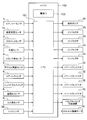
- FIG. 2 is a functional block diagram of a CPU of the ECU according to the embodiment.
- MPI multi-cylinder fuel injection
- the air taken into the engine 65 passes through the air cleaner 60 and is guided to the hot wire type air flow sensor 1.
- a hot wire air flow sensor is used for the hot wire air flow sensor 1.
- a signal corresponding to the amount of intake air is output from the hot wire air flow sensor 1 and an intake air temperature signal measured by an intake air temperature sensor 1a using a thermistor built in the hot wire air flow sensor 1 is output.
- the intake air passes through a duct 61 connected to an air cleaner 60 and a throttle valve 40 that controls an air flow rate, and enters a collector 62.
- the throttle valve 40 is provided with a throttle sensor 2 for detecting the degree of opening of the throttle valve 40, and is driven by a throttle drive motor 41 driven by a control ECU (Engine ⁇ Control ⁇ Unit) 100 as a signal processing device.
- the air that has entered the collector 62 is distributed to each intake pipe 63 that is directly connected to the engine 65, and is drawn into the cylinder 66 (combustion chamber) via the intake valve 35.
- a valve timing variable mechanism 37 with a cam angle sensor 9 is provided in a valve drive system of the intake valve 35 and the exhaust valve 36, and performs feedback control toward a target angle. Further, pulses are output from the crank angle sensor 4 attached to the cylinder blocks (hereinafter, sometimes referred to as engine blocks) 66 and 67 at predetermined crank angles, and these outputs are input to the ECU 100.
- the fuel is sucked from the fuel tank 21 by the fuel pump 20, pressurized, regulated to a constant pressure by the pressure regulator 22, and injected into the intake pipe 63 from the injector 23 provided in the intake pipe 63.
- a throttle sensor 2 for detecting the opening of the throttle valve 40 is attached to the throttle valve 40, and this sensor signal is input to the ECU 100 to perform feedback control of the opening of the throttle valve 40 and to control the fully closed position. It performs detection and acceleration detection.
- the target opening of the feedback is obtained from the accelerator depression amount of the driver obtained by the accelerator opening sensor 5 and the idle speed control, that is, the ISC control.
- a water temperature sensor 3 for detecting a cooling water temperature is attached to the engine 65, and this sensor signal is input to the ECU 100 to detect a warm-up state of the engine 65 and increase the fuel injection amount from the injector 23.
- the ignition timing of the ignition plug 33, ON / OFF of the radiator fan 68, and setting of the target rotation speed at the time of idling are attached to calculate a target rotation speed at idle and a load correction amount. I have.
- the air-fuel ratio sensor 8 is attached to the exhaust pipe 64 of the engine 65 and outputs a signal corresponding to the oxygen concentration of the exhaust gas discharged to the exhaust pipe 64 via the exhaust valve 36. This sensor signal is input to the ECU 100, and adjusts the fuel injection pulse width of the injector 23 so that the target air-fuel ratio is obtained according to the driving situation.
- the ECU 100 includes a microcomputer having a CPU (Central Processing Unit) 101, a power supply IC 102, a RAM (Random Access Memory) not shown, a ROM (Read Only Memory) not shown, and the like. I have.
- the CPU 101 of the ECU 100 executes various controls related to the operation of the engine 65 by executing various control programs stored in the ROM.
- the signals and the like input to the CPU 101 of the ECU 100 will be summarized with reference to the drawing, and the air flow sensor 1 and the intake temperature sensor 1a, throttle sensor 2, water temperature sensor 3, crank angle sensor 4, and accelerator opening Signals from the degree sensor 5, the air conditioner switch 6, the neutral switch 7, the air-fuel ratio sensor 8, the cam angle sensor 9, and the knock sensor 34 are input.
- An output signal from the CPU 101 of the ECU 100 is output to the fuel pump 20, the injector 23, the power transistor 32 including an ignition switch of the ignition plug 33, a variable valve timing mechanism 37, a throttle drive motor 41, and the like.
- the signal from the knock sensor 34 attached to the cylinder block 67 is input to the CPU 101, and the CPU 101 performs a knock determination for identifying noise other than knock and knock.
- the knock determination is made, the ignition timing is retarded. And a correction for suppressing the occurrence of knock is performed. Based on the corrected target ignition timing, the power supply timing of the power transistor 32 is controlled.
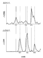
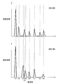
- FIG. 3 shows the output of the pressure sensor (the output of the pressure sensor that detects the pressure in the cylinder (inside the cylinder 66)) and the output of the knock sensor (the output of the knock sensor 34 that detects the vibration of the cylinder 66 of the cylinder block 67) in the cycle in which the knock occurred.
- FIG. 9 is a diagram showing a result of frequency analysis of (output).
- the vertical axis (knock strength) in the upper diagram of FIG. 3 is the square of the output (pressure) of the pressure sensor, and the unit is [MPa ⁇ 2].
- the vertical axis (knock strength) in the lower diagram of FIG. 3 is the square of the output (voltage) of the knock sensor 34, and the unit is [V ⁇ 2].
- the specific frequencies (Pf1, Pf2, Pf3) of the pressure waves, which are the root causes of the vibration, and the specific frequencies (Kf1, Kf2, Kf3) of the knock sensor signal detected as the vibration of the cylinder blocks (66, 67). ) Do not always match. This is because the result of the impact force input to the engine block (66, 67) when the pressure wave collides with the wall surface passes through the characteristics of the engine block (66, 67) and appears as a knock sensor output. Also, the relationship between the values of the frequency components is different. That is, in the knock sensor 34, the signal strengths of the specific frequencies Kf1 and Kf3 at the position sandwiching the center specific frequency Kf2 are smaller than that of the central specific frequency Kf2.
- the knock sensor signal Knock occurs at the same specific frequency (Kf1, Kf2, Kf3).
- knock occurs at a specific frequency (Pf1, Pf2, Pf3) of the pressure wave obtained by the pressure sensor mounted inside the cylinder 66.
- FIG. 4 shows a linear relationship between the signal value (signal strength) of the knock sensor signal at a specific frequency and the signal value (signal strength) of the pressure sensor signal at a specific frequency.
- FIG. 4 shows the intensity P (Pf1), P (Pf2) of the pressure sensor signal at the specific frequency Pf1, Pf2 and the intensity K (Kf1), K (Kf2) of the knock sensor signal at the specific frequency Kf1, Kf2 in FIG.
- the knock intensity K (Kfi) of the specific frequency of the knock sensor signal is corrected by the knock intensity P (Pfi) of the specific frequency of the pressure sensor signal in accordance with the change of the specific frequency by the engine blocks (66, 67).
- K (Kf1) is corrected to P (Pf1)
- K (Kf2) is corrected to P (Pf2).
- the weight coefficient of the low frequency component (K (Kf1)) of the knock sensor signal is set to 1 and the weight coefficient of the high frequency component (K (Kf2)) is set to 2 to increase.
- the knock intensity (in-cylinder pressure intensity) of the pressure sensor signal at the specific frequency can be calculated from the knock intensity of the specific frequency of the knock sensor signal.
- the relationship between the specific frequency (Pf1, Pf2, etc.) of the pressure wave corresponding to the specific frequency (Kf1, Kf2, etc.) of the knock sensor signal is stored in RAM or ROM for each engine operating state. .
- the weight coefficient for calculating the knock intensity P (Pfi) of the specific frequency of the pressure sensor signal from the knock intensity K (Kfi) of the specific frequency of the knock sensor signal is stored together in the RAM or ROM.
- the CPU 101 of the ECU 100 uses the relationship between the specific frequency (Kf1, Kf2, etc.) of the knock sensor signal and the specific frequency (Pf1, Pf2, etc.) of the pressure wave stored in the RAM or ROM, and the weight coefficient.
- a knock intensity (in-cylinder pressure intensity, P (Pfi)) of a specific frequency of the pressure sensor signal is calculated from the knock sensor signal. Then, CPU 101 determines the presence or absence of knock based on the knock intensity (in-cylinder pressure intensity) of the specific frequency of the calculated pressure sensor signal.
- FIG. 5 is a calculation chart illustrating a procedure for determining the presence or absence of knocking in the present embodiment. Each step in FIG. 5 is performed by the CPU 101 of the ECU 100. Hereinafter, processing of each operation block in FIG. 5 will be described.
- knock detection is performed in accordance with the state of the engine 65 (engine operating state) such as the cylinder number of the engine 65, the number of revolutions of the engine 65, the load, and the cooling water temperature detected by the water temperature sensor 3.
- the state of the engine 65 engine operating state
- the frequency band cutoff frequency or pass band
- a filter ID map in which a plurality of later-described filters having different cutoff frequencies or passbands are registered as individual codes is stored. Then, the CPU 101 selects a corresponding filter ID from the filter ID map according to the above-described engine operation state (S501). Although a filter ID map will be described later, the filter ID is associated with a filter coefficient for setting a filter characteristic. Therefore, by selecting a filter ID from the filter ID map, it is possible to set a knock detection filter in which a frequency band (cutoff frequency or pass band), an attenuation band, and the like corresponding to the filter ID are determined (S502). .
- Knock sensor 34 detects vibration of engine 65 (S301), and the AD converter converts the detection result into a digital signal (S302).
- the knock sensor output of knock sensor 34 is output as a signal in a desired frequency band by the knock detection filter set in S501.
- a knock detection filter band-pass filter
- a cutoff frequency or a pass band whose resonance frequency (specific frequency) is 7 kHz, 9 kHz, or 12 kHz is set in association with the selected filter ID.
- 3 illustrates three passed frequency components. That is, the CPU 101 processes the knock sensor output signal of the knock sensor 34 using the knock detection filter set by selecting the filter ID in S501. Then, the CPU 101 calculates the knock intensity K (Kfi) of each resonance frequency (Kfi) from the output of the knock detection filter (S303).
- the CPU 101 uses the relationship between the specific frequency (Kf1, Kf2, etc.) of the knock sensor signal and the specific frequency (Pf1, Pf2, etc.) of the pressure wave and the weight coefficient stored in the RAM or ROM as described above. Then, the knock intensity (in-cylinder pressure intensity) of the specific frequency of the pressure sensor signal is calculated from the knock sensor signal. That is, the CPU 101 calculates the specific frequency (Pfi) of the pressure wave corresponding to the specific frequency (7 kHz, 9 kHz, 12 kHz) of the knock sensor signal based on the engine operating state such as the engine speed and the load.
- the CPU 101 calculates a weight coefficient corresponding to the engine operating state, and calculates a knock intensity (P (Pfi)) of the pressure sensor signal at the specific frequency based on the correspondence between the weight coefficient and the specific frequency (Pfi). (S303).
- the CPU 101 obtains a knock determination threshold value Ith based on the rotation speed Ne of the engine 65 (S307). Specifically, the CPU 101 refers to the map data (data table) in which the rotation speed Ne of the engine 65 (the operating state of the engine 65) and the knock determination threshold value are associated in advance, and determines the knock from the rotation speed Ne of the engine 65. The threshold value Ith is obtained. The CPU 101 determines the presence or absence of knock by comparing the knock index I with the knock determination threshold value Ith, and outputs the knock determination result (S308).
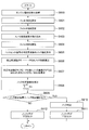
- FIG. 6 is a calculation flowchart illustrating the procedure of knock determination and knock control in the present embodiment described with reference to FIG.
- the CPU 101 detects a signal indicating the state of the engine 65 such as the cylinder number of the engine 65, the number of revolutions of the engine 65, the load, and the cooling water temperature detected by the water temperature sensor 3, corresponding to S501 in FIG. Calculation of an engine operation state (may be called an engine operation condition) is performed (S600).
- the CPU 101 selects a filter ID from the filter ID map based on the engine operating state (S601).
- the RAM or the ROM of the ECU 100 stores a filter ID map described later and a filter coefficient corresponding to each filter ID. Therefore, by selecting a filter ID in S601, the CPU 101 sets a knock detection filter such as a desired frequency band (cutoff frequency or pass band) or an attenuation band using the corresponding filter coefficient (S602). ).
- the CPU 101 performs A / D conversion of the knock signal from the knock sensor 34 and takes in the A / D conversion result (S603).
- the CPU 101 performs a filtering process on the knock signal that has been A / D converted using the knock detection filter set in S602 (S604).
- the CPU 101 calculates the knock intensity at a specific frequency of the knock sensor signal based on the filtered knock signal (S605).
- the relationship between the specific frequency (Pf1, Pf2, etc.) of the pressure wave corresponding to the specific frequency (Kf1, Kf2, etc.) of the knock sensor signal is stored in the RAM or ROM for each engine operating state.
- the CPU 101 uses the relationship between the specific frequency (Kf1, Kf2, etc.) of the knock sensor signal and the specific frequency (Pf1, Pf2, etc.) of the pressure wave stored in the RAM or ROM, and the knock sensor
- the knock intensity (in-cylinder pressure intensity, P (Pfi)) of the specific frequency of the pressure sensor signal is calculated from the signal (S606).
- the relationship between the specific frequency (Kf1, Kf2, etc.) of the knock sensor signal and the specific frequency (Pf1, Pf2, etc.) of the pressure wave stored in the RAM or ROM as described above, and the weighting factor are set as follows.
- the knock intensity (in-cylinder pressure intensity) of the specific frequency of the pressure sensor signal is calculated using the pressure sensor signal, but the present invention is not limited to this. That is, without performing this conversion, it is also possible to perform a subsequent knock determination using the knock intensity (K (Kfi)) of the specific frequency (Kf1, Kf2, etc.) of the knock sensor signal.
- the knock determination index I is larger than the knock determination threshold Ith (S609), it is determined that knock has occurred (S610), and a knock flag “1” is set (S611). On the other hand, when the knock determination index I is equal to or smaller than the knock determination threshold Ith (S609), the knock flag is set to "0" (S612). When the knock flag becomes 1, the CPU 101 controls the ignition timing of the ignition plug 33 to be retarded so that knock does not occur.
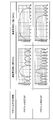
- FIG. 7 shows an example of a filter setting control example by the CPU 101 of the ECU 100 in the present embodiment.
- a plurality of filters described later having different cutoff frequencies or passbands are stored as individual codes (ID1, ID2, ID3, ID4, ID5, ID6) in the RAM or ROM of the ECU 100.
- the registered filter ID map of FIG. 7 is stored.
- the CPU 101 selects a corresponding filter ID from the filter ID map according to the engine operating state (the cylinder number of the engine 65, the number of revolutions of the engine 65, the load, the cooling water temperature detected by the water temperature sensor 3, etc.).
- a filter coefficient for setting a filter characteristic is linked to the filter ID. Therefore, by selecting a filter ID from the filter ID map, it is possible to set a knock detection filter in which a frequency band (cutoff frequency or pass band), an attenuation band, and the like corresponding to the filter ID are determined.
- FIG. 7 shows an example of a three-stage second-order IIR filter as filter ID1.
- filter coefficients such as a11, a12, w1 (n-1), w1 (n-2), b00, b10, b11, and b12 are set.
- filter coefficients are set for the second and third-order secondary IIR filters. With these filter coefficients, filter characteristics such as what frequency band (cutoff frequency or pass band) of a signal to pass or what to do with an attenuation band are determined.
- the CPU 101 processes the detection signal of the knock sensor 34 using a knock detection filter whose filter characteristics are determined by a filter type (such as an IIR filter or an FIR filter) and a filter coefficient associated with the selected filter ID. .
- a filter type such as an IIR filter or an FIR filter
- the filter ID is associated with the filter type and the filter coefficient in advance, and the CPU 101 can select a preset filter ID according to the engine operating state.
- the filter type and the filter coefficient are set so as to have desired filter characteristics associated with the filter ID, and it is possible to perform a knock determination using the knock detection filter based on the filter type and the filter coefficient.
- the filter type and the filter coefficient are stored in the RAM or the ROM for each filter so that a plurality of filters having different desired frequency bands (cutoff frequencies or passbands) are obtained in advance. Have been. It is desirable that the desired frequency band (cutoff frequency or pass band), that is, the filter characteristic, is set so that knock detection can be accurately performed in a general engine.
- the ECU 100 according to the present embodiment stores in advance in the RAM or ROM only the filter type and the filter coefficient for satisfying the filter characteristic (cutoff frequency or pass band), and stores the filter characteristic (cutoff frequency or cutoff frequency). It has a function of associating a filter ID with a frequency or a pass band.
- the person who performs the adaptation process of the ECU 100 can complete the adaptation process by setting only which filter ID (that is, which filter characteristic) corresponds to which engine operating state. Therefore, there is no need to perform complicated filter type and filter coefficient settings, and it is possible to provide an ECU that can easily perform the adaptation process.
- the filter ID map is divided into a plurality of filter ID maps for each filter channel. Therefore, the CPU 101 first selects a filter ID map based on the engine operating state, and then selects a corresponding filter ID from the selected filter ID map. In FIG. 8, assuming that there are m filter ID maps, the filter IDs are shown as filter 1ID to filter mID. When the filter ID is selected, the corresponding filter type and filter coefficient are set, whereby the filter setting process for determining which filter among the filters 1 to m is used is completed.
- FIG. 9 illustrates an example of a filter that can be selected by the CPU 101 of the ECU 100 in the present embodiment, and illustrates an example of a filter of a filter type that can be selected in the filter ID maps of FIGS. 7 and 8.
- FIG. 9 illustrates an example of filter characteristics for each number of IIR filter stages. As is clear from FIG. 9, the filter characteristic becomes steeper as the number of filter stages increases. Further, by appropriately setting the filter coefficient, it is possible to change the cut frequency (Fc1, Fc2), that is, the pass band.
- FIG. 10 illustrates another example of a filter that can be selected by the CPU 101 of the ECU 100 in the present embodiment, and illustrates an example of a filter of a filter type that can be selected in the filter ID maps of FIGS. 7 and 8.
- FIG. 10 illustrates another example of filter characteristics for each FIR filter TAP stage number. As is clear from FIG. 10, it can be seen that the larger the number of filter stages, the narrower the pass band width of the filter.
- FIG. 11 is a diagram illustrating a specific frequency and a signal strength of a knock sensor signal for each cylinder in which knock has occurred, and is a diagram illustrating the necessity of the above-described filter switching function for each cylinder.
- the frequency K2 is a specific frequency found only in the second cylinder
- the frequency K7 is a specific frequency found only in the first cylinder.
- the characteristics from the cylinder in which knock occurs to the knock sensor differ for each cylinder. Such a difference occurs because the characteristics depend on the distance, the route, the shape of the route, etc., through which the vibration applied to the engine blocks (66, 67) by the pressure wave passes. For example, it is necessary to perform signal correction in consideration of the characteristics of the engine blocks (66, 67) by changing a specific frequency selected for each cylinder.
- the filter characteristics can be set in consideration of the characteristics of the engine blocks (66, 67) corresponding to the respective cylinders.
- the cylinder number of the engine 65 is configured to be input to the CPU 101 as one of the engine operating states. Is done.
- the CPU 101 selects a filter ID based on the operating cylinder number, and sets a knock detection filter having a desired filter characteristic for the cylinder number associated with the filter ID. Therefore, the conversion from pressure to vibration can be appropriately handled, and the pressure wave intensity can be predicted more precisely.
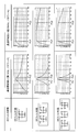
- FIG. 12 is an example of the concept of the filter setting by the CPU 101 of the ECU 100 in the present embodiment and the relationship between the state of the engine 65, the cylinder number, and the frequency of occurrence of knock, and illustrates one cylinder of 1200 rpm, two cylinders, and one cylinder of 2400 rpm. It is the graph which also described the frequency analysis result of two cylinders.
- two cylinders at 1200 rpm and one cylinder at 2400 rpm have peaks at almost the same frequency.
- two cylinders at 1200 rpm and one cylinder at 2400 rpm have the same filter requirements, and they can be integrated, and a filter with the same filter ID can be used. Therefore, it is possible to easily set complicated filter coefficients.
- FIG. 13 shows an example of the relationship between the state of the engine 65, the cylinder number, and the frequency of occurrence of knock, and the setting of the filter by the CPU 101 of the ECU 100 in the present embodiment.
- FIG. 14 is a diagram for explaining the necessity of a filter switching function of the relationship between the state of the engine 65 and the frequency of knocking by the CPU 101 of the ECU 100 in the present embodiment, and shows a knock sensor signal for each cooling water temperature when knocking occurs.
- FIG. 3 is a diagram showing a specific frequency and a signal strength of FIG.
- the frequencies K2, K4, and K8 are specific frequencies only at low water temperatures
- the frequencies K3 and K5 are specific frequencies only at high water temperatures.
- the coolant temperature at the time when knock occurs changes the specific frequency of the pressure wave due to the change in the in-cylinder temperature and also changes the characteristics of the engine block.
- the change in the characteristics of the engine block may be caused by a change in the speed of sound in water due to a change in temperature.
- the specific frequency appearing as a signal of knock sensor 34 changes.
- the filter characteristics are set in consideration of the characteristics of the engine block corresponding to the cooling water temperature.
- the cooling water temperature is input to the CPU 101 as one of the engine operating states, and a filter ID is set based on the cooling water temperature so as to have a desired filter characteristic.
- the CPU 101 selects a filter ID based on the cooling water temperature, and sets a knock detection filter having desired filter characteristics for the cooling water temperature associated with the filter ID. As a result, it is possible to appropriately handle the conversion from pressure to vibration, and it is possible to more accurately predict the pressure wave intensity.
- FIG. 15 is an example of the relationship between the state of the engine 65, the cylinder number, and the frequency of occurrence of knock, and the setting of a filter by the CPU 101 of the ECU 100 in the present embodiment.
- FIG. 16 is a functional block diagram of the CPU 101 that performs knock sensor signal correction for each cylinder from the knock sensor signal detection and calculates knock strength.
- the signal detected by the knock sensor 34 is corrected in consideration of the effect of the engine block (knock sensor signal correction).
- the cylinder number of the engine 65 or the coolant temperature in each cylinder is determined by the CPU 101.
- the corresponding filter ID is selected.
- the knock sensor signal is processed by a knock detection filter having a filter characteristic associated with the filter ID, and a knock intensity (pressure wave intensity) is calculated based on the processing result.
- the signal processing device (ECU 100) of the present embodiment filters the output signal from the sensor (knock sensor 34) mounted on the vehicle. Further, in the signal processing device (ECU 100) of the present embodiment, a filter type (IIR filter, FIR filter, or the like) or a filter coefficient (a11, a12, w1 (FIG. 7) of FIG. n-1), w1 (n-2), b00, b10, b11, b12, etc.) are set for a plurality of different filters, and an individual code (filter ID) is set for each of the plurality of filters.
- a filter type IIR filter, FIR filter, or the like
- a filter coefficient a11, a12, w1 (FIG. 7) of FIG. n-1), w1 (n-2), b00, b10, b11, b12, etc.
- the signal processing device (ECU 100) of the present embodiment selects an individual code (filter ID) based on the engine operating state, selects a corresponding filter, and uses the selected filter to generate a sensor (knock sensor 34). )
- the sensor is a knock sensor 34 that detects knock of an engine 65 mounted on a vehicle.
- the CPU 101 calculates the knock intensity (K (Kfi)) of the knock sensor signal at a specific frequency based on the signal processed by the selected filter.
- the signal processing device (ECU 100) stores a relationship between a specific frequency (Kfi) of the knock sensor signal and a specific frequency (Pfi) of the pressure wave in the cylinder corresponding to the specific frequency of the knock sensor signal for each engine operating state (not shown).
- CPU 101 calculates a knock intensity (K (Kfi)) of the knock sensor signal at a specific frequency based on the signal processed by the selected filter, and stores the knock sensor stored in the storage unit.
- the knock intensity (P) of the specific frequency of the pressure sensor signal for detecting the pressure wave in the cylinder from the knock sensor signal is used. It is desirable to calculate (Pfi)).
- an individual code is set for the relationship between the specific frequency (Kfi) of the knock sensor signal and the specific frequency (Pfi) of the pressure wave, and the weighting coefficient, and the CPU 101 determines based on the engine operating state.
- the individual code (filter ID) is selected by the operator, it is desirable to set the relationship between the specific frequency (Kfi) of the knock sensor signal and the specific frequency (Pfi) of the pressure wave corresponding to the individual code (filter ID) or the weight coefficient.
- a filter type for setting a plurality of filters having different cutoff frequencies or pass bands is set.
- a storage unit for storing filter coefficients, and has an individual code assigning function for associating an individual code (filter ID) with each of a plurality of filters.
- a corresponding filter is selected by selecting an individual code (filter ID) based on the selected code, and a CPU 101 that processes an output signal from a sensor (knock sensor 34) using the selected filter is provided.
- each of the above-described configurations, functions, processing units, processing means, and the like may be partially or entirely realized by hardware by, for example, designing an integrated circuit.
- the above-described configurations, functions, and the like may be realized by software by a processor interpreting and executing a program that realizes each function.
- Information such as a program, a table, and a file for realizing each function can be stored in a memory, a hard disk, a storage device such as an SSD (Solid State Drive), or a recording medium such as an IC card, an SD card, or a DVD.
- control lines and information lines are those that are considered necessary for explanation, and do not necessarily indicate all control lines and information lines on the product. In fact, it can be considered that almost all components are connected to each other.
Landscapes
- Engineering & Computer Science (AREA)
- Chemical & Material Sciences (AREA)
- Combustion & Propulsion (AREA)
- Mechanical Engineering (AREA)
- General Engineering & Computer Science (AREA)
- Computer Hardware Design (AREA)
- Microelectronics & Electronic Packaging (AREA)
- Physics & Mathematics (AREA)
- General Physics & Mathematics (AREA)
- Combined Controls Of Internal Combustion Engines (AREA)
- Testing Of Devices, Machine Parts, Or Other Structures Thereof (AREA)
- Measurement Of Mechanical Vibrations Or Ultrasonic Waves (AREA)
Abstract
Description
[数1]
P(Pf1)+P(Pf2)=K(Kf1)+2K(Kf2) ・・・(1)
図5は、本実施形態におけるノック有無を判定する手順を説明する演算チャートである。図5の各ステップは、ECU100のCPU101が実施するものとする。以下、図5における各演算ブロックの処理について説明する。
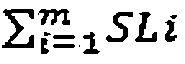
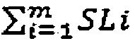
図7は、本実施形態におけるECU100のCPU101によるフィルタ設定制御例の一例を示している。

Claims (8)
- 車両に搭載されたセンサからの出力信号をフィルタ処理する信号処理装置であって、
カットオフ周波数、又は通過帯域のフィルタ特性を設定するフィルタ種類又はフィルタ係数の異なる複数のフィルタに対し設定され、
前記複数のフィルタのそれぞれに対し、個別コードが設定され、
エンジン運転状態に基づいて前記個別コードを選択することで対応するフィルタが選択され、選択された前記フィルタを用いて前記センサからの出力信号を処理するCPUを備えた信号処理装置。 - 請求項1に記載の信号処理装置において、
前記センサは、前記車両に搭載されたエンジンのノックを検出するノックセンサである信号処理装置。 - 請求項2に記載の信号処理装置において、
前記CPUは、選択された前記フィルタにより処理された信号に基づいてノックセンサ信号の特定周波数のノック強度(K(Kfi))を算出する信号処理装置。 - 請求項2に記載の信号処理装置において、
エンジン運転状態毎にノックセンサ信号の特定周波数(Kfi)に対応する筒内の圧力波の特定周波数(Pfi)との関係を記憶する記憶部を備え、
前記CPUは、選択された前記フィルタにより処理された信号に基づいてノックセンサ信号の特定周波数のノック強度(K(Kfi))を算出し、前記記憶部に記憶されたノックセンサ信号の特定周波数(Kfi)と圧力波の特定周波数(Pfi)との関係、及び重み係数を用いて、ノックセンサ信号から前記筒内の圧力波を検出する圧力センサ信号の特定周波数のノック強度(P(Pfi))を算出する信号処理装置。 - 請求項4に記載の信号処理装置において、
ノックセンサ信号の特定周波数(Kfi)と圧力波の特定周波数(Pfi)との関係、及び重み係数に対し、フィルタIDが設定され、
前記CPUがエンジン運転状態に基づいてフィルタIDを選択した場合に、これに対応するノックセンサ信号の特定周波数(Kfi)と圧力波の特定周波数(Pfi)との関係、又は重み係数が設定される信号処理装置。 - 請求項4に記載の信号処理装置において、
前記CPUは、特定周波数(Pfi)毎にノック強度(P(Pfi))に対するバックグラウンドレベルの加重平均(BGLi)の比SLi=P(Pfi)/BGLiを算出し、特定周波数がm個あった場合に、
を計算することで、ノック判定指標Iを算出し、前記ノック判定指標Iがノック判定閾値Ithよりも大きい場合にノックが発生しているものと判定する信号処理装置。
- 請求項1に記載の信号処理装置において、
前記エンジン運転状態は、前記エンジンの気筒番号、前記エンジンの回転数、前記エンジンの負荷、又は水温センサにより検出される冷却水温のうち少なくとも一つである信号処理装置。 - センサを備えたエンジンを制御するエンジン制御装置において、
カットオフ周波数、又は通過帯域の異なる複数のフィルタを設定するためのフィルタ種類及びフィルタ係数を記憶する記憶部を備え、
前記複数のフィルタのそれぞれに対し個別コードを対応付けできるような個別コード付与機能を有し、
エンジン運転状態に基づいて前記個別コードを選択することで対応するフィルタが選択され、選択された前記フィルタを用いて前記センサからの出力信号を処理するCPUを備えたエンジン制御装置。
Priority Applications (4)
| Application Number | Priority Date | Filing Date | Title |
|---|---|---|---|
| US17/253,860 US11261811B2 (en) | 2018-08-30 | 2019-08-08 | Signal processing device, and engine control device |
| JP2020540221A JP7170048B2 (ja) | 2018-08-30 | 2019-08-08 | 信号処理装置及びエンジン制御装置 |
| DE112019002425.6T DE112019002425B4 (de) | 2018-08-30 | 2019-08-08 | Signalverarbeitungsvorrichtung und kraftmaschinensteuervorrichtung |
| US17/581,584 US11635036B2 (en) | 2018-08-30 | 2022-01-21 | Signal processing device, and engine control device |
Applications Claiming Priority (2)
| Application Number | Priority Date | Filing Date | Title |
|---|---|---|---|
| JP2018-161031 | 2018-08-30 | ||
| JP2018161031 | 2018-08-30 |
Related Child Applications (2)
| Application Number | Title | Priority Date | Filing Date |
|---|---|---|---|
| US17/253,860 A-371-Of-International US11261811B2 (en) | 2018-08-30 | 2019-08-08 | Signal processing device, and engine control device |
| US17/581,584 Continuation US11635036B2 (en) | 2018-08-30 | 2022-01-21 | Signal processing device, and engine control device |
Publications (1)
| Publication Number | Publication Date |
|---|---|
| WO2020045026A1 true WO2020045026A1 (ja) | 2020-03-05 |
Family
ID=69644891
Family Applications (1)
| Application Number | Title | Priority Date | Filing Date |
|---|---|---|---|
| PCT/JP2019/031314 Ceased WO2020045026A1 (ja) | 2018-08-30 | 2019-08-08 | 信号処理装置及びエンジン制御装置 |
Country Status (4)
| Country | Link |
|---|---|
| US (2) | US11261811B2 (ja) |
| JP (1) | JP7170048B2 (ja) |
| DE (1) | DE112019002425B4 (ja) |
| WO (1) | WO2020045026A1 (ja) |
Citations (10)
| Publication number | Priority date | Publication date | Assignee | Title |
|---|---|---|---|---|
| JPH06249047A (ja) * | 1993-02-26 | 1994-09-06 | Hitachi Ltd | 内燃機関のノッキング検出装置 |
| JPH07139415A (ja) * | 1992-12-04 | 1995-05-30 | Nippondenso Co Ltd | 内燃機関用ノッキング検出装置 |
| JP2001234800A (ja) * | 2000-02-25 | 2001-08-31 | Toyota Motor Corp | 燃料噴射制御装置 |
| JP2006291786A (ja) * | 2005-04-08 | 2006-10-26 | Denso Corp | 車両の制御装置 |
| JP2009042027A (ja) * | 2007-08-08 | 2009-02-26 | Denso Corp | 内燃機関のノック判定装置 |
| JP2011179322A (ja) * | 2010-02-26 | 2011-09-15 | Suzuki Motor Corp | ノック制御の適合方法、適合装置、および、ノック制御装置 |
| JP2011179323A (ja) * | 2010-02-26 | 2011-09-15 | Suzuki Motor Corp | ノックセンサ取付位置の適合方法、適合装置、制御装置、及びシリンダブロック |
| WO2017141582A1 (ja) * | 2016-02-16 | 2017-08-24 | 日立オートモティブシステムズ株式会社 | ノッキング検出装置、内燃機関制御装置 |
| JP2017160809A (ja) * | 2016-03-08 | 2017-09-14 | 日立オートモティブシステムズ株式会社 | エンジン制御装置 |
| JP2018003631A (ja) * | 2016-06-28 | 2018-01-11 | 日立オートモティブシステムズ株式会社 | 内燃機関の制御装置及びノック判定方法 |
Family Cites Families (28)
| Publication number | Priority date | Publication date | Assignee | Title |
|---|---|---|---|---|
| JPS56637A (en) | 1979-06-15 | 1981-01-07 | Nippon Soken Inc | Knocking detecting unit for internal combustion engine |
| JPS5845520A (ja) | 1981-09-11 | 1983-03-16 | Matsushita Electric Ind Co Ltd | ノツキング検出装置 |
| JPS5946519A (ja) * | 1982-04-08 | 1984-03-15 | Nippon Denso Co Ltd | 内燃機関用ノツキング検出装置 |
| JPS59185874A (ja) * | 1983-04-08 | 1984-10-22 | Hitachi Ltd | 内燃機関の点火装置 |
| JPH0772527B2 (ja) | 1987-05-25 | 1995-08-02 | 日本電装株式会社 | 内燃機関用ノッキング検出装置 |
| US5052214A (en) * | 1989-01-03 | 1991-10-01 | Luxtron Corporation | Knock detector using optical fiber thermometer |
| US5206809A (en) * | 1989-09-04 | 1993-04-27 | Nissan Motor Company, Limited | Heat measuring system for detecting knock in internal combustion engine |
| JP3118022B2 (ja) * | 1991-07-04 | 2000-12-18 | 富士重工業株式会社 | 複数バンクを有する多気筒エンジンのノック検出方法 |
| US5522254A (en) | 1992-12-04 | 1996-06-04 | Nippondenso Co., Ltd. | Knock sensing apparatus for internal combustion engine |
| US5408863A (en) * | 1993-04-15 | 1995-04-25 | Hughes Aircraft Company | Knock detector for internal combustion engine |
| JP3341391B2 (ja) * | 1993-10-06 | 2002-11-05 | 株式会社デンソー | 内燃機関のノッキング検出装置 |
| SE505543C2 (sv) * | 1995-12-27 | 1997-09-15 | Mecel Ab | Metod för reglering av knackning i en förbränningsmotor |
| WO2002014822A1 (de) * | 2000-08-11 | 2002-02-21 | Robert Bosch Gmbh | Klopferkennung bei brennkraftmaschinen mit mofidizierung bei änderung einer filtercharakteristik oder zylinderindividueller änderung |
| GB0112338D0 (en) * | 2001-05-21 | 2001-07-11 | Ricardo Consulting Eng | Improved engine management |
| JP2003329514A (ja) * | 2002-05-10 | 2003-11-19 | Denso Corp | ノックセンサ信号処理装置及びその設計方法 |
| JP4134797B2 (ja) * | 2003-04-14 | 2008-08-20 | 株式会社デンソー | ノッキング検出装置 |
| JP4627150B2 (ja) * | 2004-05-24 | 2011-02-09 | 三菱電機株式会社 | 信号処理装置 |
| JP2006161649A (ja) * | 2004-12-06 | 2006-06-22 | Denso Corp | ノック検出装置 |
| JP4773888B2 (ja) * | 2006-06-02 | 2011-09-14 | 本田技研工業株式会社 | 内燃機関の点火時期制御装置 |
| JP4335244B2 (ja) * | 2006-09-07 | 2009-09-30 | 三菱電機株式会社 | 内燃機関用ノック制御装置 |
| JP4427071B2 (ja) * | 2007-04-17 | 2010-03-03 | 三菱電機株式会社 | 内燃機関の制御装置 |
| CA2609718C (en) * | 2007-11-27 | 2010-03-23 | Westport Power Inc. | Method and apparatus for determining a normal combustion characteristic for an internal combustion engine from an accelerometer signal |
| DE102008004442B3 (de) * | 2008-01-15 | 2009-07-23 | Continental Automotive Gmbh | Verfahren und System zur Filterung eines gestörten Zylinderdrucksignals einer Zylinders einer Brennkraftmaschine |
| US10502177B2 (en) * | 2013-08-12 | 2019-12-10 | Ford Global Technologies, Llc | Methods and systems for improving engine starting |
| US20160265453A1 (en) * | 2015-03-13 | 2016-09-15 | General Electric Company | Joint time-frequency and wavelet analysis of knock sensor signal |
| JP6591389B2 (ja) * | 2016-12-12 | 2019-10-16 | 日立オートモティブシステムズ株式会社 | 内燃機関のノッキング検出装置 |
| US10393050B2 (en) * | 2017-10-30 | 2019-08-27 | Ai Alpine Us Bidco Inc. | Estimation of cylinder conditions using a knock sensor |
| DE102017220129B4 (de) * | 2017-11-13 | 2023-10-26 | Robert Bosch Gmbh | Verfahren und Vorrichtung zur Klopfregelung einer Brennkraftmaschine |
-
2019
- 2019-08-08 JP JP2020540221A patent/JP7170048B2/ja active Active
- 2019-08-08 WO PCT/JP2019/031314 patent/WO2020045026A1/ja not_active Ceased
- 2019-08-08 US US17/253,860 patent/US11261811B2/en active Active
- 2019-08-08 DE DE112019002425.6T patent/DE112019002425B4/de active Active
-
2022
- 2022-01-21 US US17/581,584 patent/US11635036B2/en active Active
Patent Citations (10)
| Publication number | Priority date | Publication date | Assignee | Title |
|---|---|---|---|---|
| JPH07139415A (ja) * | 1992-12-04 | 1995-05-30 | Nippondenso Co Ltd | 内燃機関用ノッキング検出装置 |
| JPH06249047A (ja) * | 1993-02-26 | 1994-09-06 | Hitachi Ltd | 内燃機関のノッキング検出装置 |
| JP2001234800A (ja) * | 2000-02-25 | 2001-08-31 | Toyota Motor Corp | 燃料噴射制御装置 |
| JP2006291786A (ja) * | 2005-04-08 | 2006-10-26 | Denso Corp | 車両の制御装置 |
| JP2009042027A (ja) * | 2007-08-08 | 2009-02-26 | Denso Corp | 内燃機関のノック判定装置 |
| JP2011179322A (ja) * | 2010-02-26 | 2011-09-15 | Suzuki Motor Corp | ノック制御の適合方法、適合装置、および、ノック制御装置 |
| JP2011179323A (ja) * | 2010-02-26 | 2011-09-15 | Suzuki Motor Corp | ノックセンサ取付位置の適合方法、適合装置、制御装置、及びシリンダブロック |
| WO2017141582A1 (ja) * | 2016-02-16 | 2017-08-24 | 日立オートモティブシステムズ株式会社 | ノッキング検出装置、内燃機関制御装置 |
| JP2017160809A (ja) * | 2016-03-08 | 2017-09-14 | 日立オートモティブシステムズ株式会社 | エンジン制御装置 |
| JP2018003631A (ja) * | 2016-06-28 | 2018-01-11 | 日立オートモティブシステムズ株式会社 | 内燃機関の制御装置及びノック判定方法 |
Also Published As
| Publication number | Publication date |
|---|---|
| US20210270198A1 (en) | 2021-09-02 |
| DE112019002425T5 (de) | 2021-02-11 |
| US11261811B2 (en) | 2022-03-01 |
| US11635036B2 (en) | 2023-04-25 |
| JPWO2020045026A1 (ja) | 2021-08-10 |
| DE112019002425B4 (de) | 2026-02-19 |
| US20220145819A1 (en) | 2022-05-12 |
| JP7170048B2 (ja) | 2022-11-11 |
Similar Documents
| Publication | Publication Date | Title |
|---|---|---|
| JP4311657B2 (ja) | 内燃機関のノック検出装置 | |
| JP4600431B2 (ja) | 内燃機関のノッキング判定装置 | |
| JP6362713B2 (ja) | ノック検出装置 | |
| CN1186608C (zh) | 内燃机的爆震判断装置 | |
| CN101213434B (zh) | 内燃机的爆震判定设备 | |
| JP4397346B2 (ja) | 内燃機関のノッキング判定装置 | |
| WO2007139042A1 (ja) | 内燃機関のノッキング判定装置およびノッキング判定方法 | |
| JP3038924B2 (ja) | 内燃機関のノッキング検出装置 | |
| KR101032595B1 (ko) | 내연기관의 노킹을 판정하기 위한 장치 및 방법 | |
| JP7170048B2 (ja) | 信号処理装置及びエンジン制御装置 | |
| WO2007139221A1 (ja) | 内燃機関のノッキング判定装置およびノッキング判定方法 | |
| JP2004339983A (ja) | 内燃機関制御装置 | |
| JPH0392569A (ja) | 内燃機関のノッキング検出装置 | |
| JP6461393B1 (ja) | 内燃機関の制御装置 | |
| JP2006348764A (ja) | 内燃機関のノッキング判定装置 | |
| JP4745198B2 (ja) | 内燃機関のノッキング判定装置、判定方法、その方法を実現するプログラムおよびそのプログラムを記録した記録媒体 | |
| JPH0390833A (ja) | 内燃機関のノッキング検出装置 | |
| JPS6123871A (ja) | 内燃機関のノツキング判定装置 | |
| JPH0392741A (ja) | 内燃機関のノッキング検出装置 | |
| JP4729536B2 (ja) | 内燃機関のノッキング判定装置、判定方法およびその方法をコンピュータで実現されるプログラムならびにそのプログラムを記録した記録媒体 | |
| JPS6146466A (ja) | 内燃機関のノツキング判定装置 | |
| JP2008069752A (ja) | 周波数の特定方法 | |
| JP2003035194A (ja) | 内燃機関用ノッキング検出装置 | |
| JPH11311147A (ja) | エンジンの気筒判定装置 | |
| JP2010019226A (ja) | 内燃機関のノック判定装置 |
Legal Events
| Date | Code | Title | Description |
|---|---|---|---|
| 121 | Ep: the epo has been informed by wipo that ep was designated in this application |
Ref document number: 19854704 Country of ref document: EP Kind code of ref document: A1 |
|
| WWE | Wipo information: entry into national phase |
Ref document number: 2020540221 Country of ref document: JP |
|
| WWE | Wipo information: entry into national phase |
Ref document number: 112019002425 Country of ref document: DE |
|
| 122 | Ep: pct application non-entry in european phase |
Ref document number: 19854704 Country of ref document: EP Kind code of ref document: A1 |
|
| WWG | Wipo information: grant in national office |
Ref document number: 112019002425 Country of ref document: DE |