WO2020036026A1 - 六フッ化タングステンの製造方法 - Google Patents
六フッ化タングステンの製造方法 Download PDFInfo
- Publication number
- WO2020036026A1 WO2020036026A1 PCT/JP2019/027628 JP2019027628W WO2020036026A1 WO 2020036026 A1 WO2020036026 A1 WO 2020036026A1 JP 2019027628 W JP2019027628 W JP 2019027628W WO 2020036026 A1 WO2020036026 A1 WO 2020036026A1
- Authority
- WO
- WIPO (PCT)
- Prior art keywords
- tungsten
- gas
- oxide film
- fluorine
- reaction vessel
- Prior art date
- Legal status (The legal status is an assumption and is not a legal conclusion. Google has not performed a legal analysis and makes no representation as to the accuracy of the status listed.)
- Ceased
Links
Images

Classifications
-
- C—CHEMISTRY; METALLURGY
- C01—INORGANIC CHEMISTRY
- C01G—COMPOUNDS CONTAINING METALS NOT COVERED BY SUBCLASSES C01D OR C01F
- C01G41/00—Compounds of tungsten
- C01G41/04—Halides
-
- C—CHEMISTRY; METALLURGY
- C01—INORGANIC CHEMISTRY
- C01G—COMPOUNDS CONTAINING METALS NOT COVERED BY SUBCLASSES C01D OR C01F
- C01G41/00—Compounds of tungsten
Definitions
- the present invention relates to a method for producing tungsten hexafluoride.
- Tungsten hexafluoride is used as a semiconductor manufacturing gas for forming metal wirings (circuits) on a semiconductor substrate.
- Tungsten is a metal having a high melting point and low electric resistance, and is widely used as a material for various electronic materials in the form of a simple metal or a silicide thereof.
- a circuit using tungsten uses tungsten hexafluoride (hereinafter sometimes referred to as WF 6 ) as a source gas and uses a chemical vapor deposition method (hereinafter referred to as a CVD method). Is formed by vapor deposition on a circuit.
- WF 6 is usually produced by a reaction between a metal tungsten alone (hereinafter, sometimes simply referred to as tungsten) and a fluorine gas (hereinafter sometimes referred to as F 2 gas).
- Patent Literature 1 discloses a method for producing a gaseous metal fluoride by reacting a simple metal with a fluorine gas, and adding or mixing a solid metal fluoride that does not react with fluorine as a molding aid in advance to the simple metal.
- a method for producing a gaseous metal fluoride is disclosed in which, after being molded under pressure, the molded body is brought into contact with and reacted with fluorine gas in a heated state.
- Patent Document 1 exemplifies WF 6 as a gaseous metal fluoride, and Table 1 of the document describes that the reaction temperature when obtaining WF 6 is 250 to 500 ° C.
- WF 6 obtained by mixing tungsten powder and sodium fluoride powder at a mass ratio of 1 to 1 and then molding into a column shape and contacting with fluorine gas while heating to 380 to 400 ° C. It is described that the gas was liquefied and collected by a cooling trap at ⁇ 80 ° C.
- Patent Document 2 discloses that the concentration of water in a nitrogen trifluoride gas (hereinafter, sometimes referred to as NF 3 ) is 1 ppm by volume or less, and tungsten gas is used in a reactor using the NF 3 gas. And a method for producing high-purity WF 6 at 200 to 400 ° C. has been disclosed. As a result of intensive studies on a method for stably purifying WF 6 to high purity, NF 3 gas after cleaning treatment has been disclosed. It is described that attention was paid to the fact that a trace amount of water was contained therein, and it was found that WF 6 with high purity was obtained by removing this water to the limit.
- NF 3 nitrogen trifluoride gas
- Patent Document 3 by using a tungsten powder and F 2 gas, and WF 6 synthetic methods using CoF 3 or AgF 2 is a metal fluoride as a catalyst is disclosed in synthesizing WF 6, WF 6 It is described that the temperature at the time of synthesis is 270 to 350 ° C.
- Patent Document 4 discloses a method for producing WF 6 by contact-reacting tungsten with a fluorinating agent.
- tungsten powder is charged into a sealed reactor, and a pressurized inert gas is injected into the reactor. after fluidizing the tungsten powder, wherein the pressurized gaseous fluorinating agent and tungsten powder was continuously fed to catalytic reaction in a fluidized state, the manufacturing method of WF 6 using fluidized reactor It is disclosed that the reaction temperature at that time is maintained at 230 ° C. to 300 ° C.
- the standard heat of formation ⁇ H is ⁇ 1722 kJ / WF 6 mol (298 K, 1 atm), and WF 6 is produced from tungsten and NF 3 gas.
- the generated standard heat of formation ⁇ H of the following reaction formula (2) is ⁇ 1458 kJ / WF 6 mol (298 K, 1 atm). Since the reaction rates of the reaction (1) and the reaction (2) are extremely high and the calorific value of WF 6 is large, the temperature of the reaction system rapidly rises in the WF 6 production process. It is known that when the temperature of the reaction system becomes high, the inner wall of the metal reactor (hereinafter, sometimes simply referred to as the reactor wall) is attacked (corroded) by the fluorine-containing gas.
- tungsten is a silver-white metal that has a metallic luster, but the surface is oxidized (corroded) by oxygen or moisture in the atmosphere, and an oxide film composed of tungsten oxide is formed, gradually losing luster. It has been known. However, it is also known that this oxidation is very thin and does not proceed to the inside. On a surface of tungsten, in an environment of high humidity, a natural oxide film (hereinafter sometimes simply referred to as an oxide film) made of a very thin oxide of tungsten is likely to be generated, and the surface of the tungsten is likely to lose gloss.
- tungsten oxides include tungsten oxide (W 2 O 3 ), tungsten dioxide (WO 2 ), and tungsten trioxide (WO 3 ).
- Patent Document 5 describes that a natural oxide film formed on a tungsten powder can be chemically removed by contact with an alkaline aqueous solution.
- Patent Documents 1 to 4 it is recommended to employ a reaction temperature exceeding 200 ° C. when producing WF 6 by bringing tungsten and F 2 gas into contact.
- the reaction speed when WF 6 is obtained by reacting tungsten with F 2 gas is extremely high and the amount of generated heat is large, so that thermal runaway of the reaction is a concern.
- a cooling mechanism such as flowing a refrigerant through a jacket of the reactor is provided, and the reactor wall during the reaction is provided. was required to be suppressed to 400 ° C. or less.
- the present invention it was resolved, compared with the prior art, and an object thereof is to provide a method of manufacturing a WF 6 that can be obtained WF 6 at a low temperature. Furthermore, the present invention is capable of obtaining a WF 6 at a low temperature that does not damage the reactor, a method of manufacturing a WF 6, and provides a method for removing the oxide film of tungsten which can be a low temperature in removing the oxide film
- the purpose is to:
- the inventors of the present invention have made intensive studies, and found that the concentration of hydrogen fluoride (hereinafter, sometimes referred to as HF) in F 2 gas is 50 ppm by volume in parts per million.
- the F 2 gas containing more or, with respect to N 2 gas, the F 2 gas containing HF concentration 50 ppm by volume or more as expressed by million by volume performs processing prior to pre-contact with a raw material of tungsten having an oxide film
- the oxide film on the surface of tungsten was removed, and then, even at a low temperature of 200 ° C. or less, tungsten quickly reacted with F 2 gas to generate WF 6 , thus completing the present invention.
- the present invention includes the following embodiments 1 to 6.
- tungsten having an oxide film is brought into contact with a fluorine gas or an inert gas containing hydrogen fluoride in an amount of 50 vol% to 50 vol% at 25 ° C.
- a method for producing tungsten hexafluoride [Aspect 3] The method for producing tungsten hexafluoride of aspect 1 or aspect 2, wherein the fluorine-containing gas used in the second step is a fluorine gas, a nitrogen trifluoride gas, or a mixed gas thereof. [Aspect 4] The method for producing tungsten hexafluoride according to aspects 1 to 3, wherein in the second step, the tungsten from which the oxide film has been removed is brought into contact with the fluorine-containing gas at a temperature of 25 ° C. or more and 200 ° C. or less.
- a method for removing an oxide film of tungsten comprising contacting tungsten having an oxide film with a fluorine gas or an inert gas containing hydrogen fluoride gas in an amount of 50 vol ppm or more and 1 vol% or less.
- Embodiment 5 Removal of the oxide film of tungsten according to aspect 5, in which tungsten having an oxide film and fluorine gas or an inert gas containing hydrogen fluoride gas in an amount of 50 vol% to 1 vol% are contacted at 25 ° C to 200 ° C. Method.
- FIG. 1 is a schematic diagram of a WF 6 synthesizer.
- FIG. 2 is a spectrum of measurement results of the raw material tungsten and the tungsten after the first step (pretreatment step) in X-ray photoelectron spectroscopy.
- the method for producing WF 6 according to the first embodiment of the present invention includes the steps of: introducing tungsten having an oxide film and F 2 gas or an inert gas containing HF in an amount of 50 ppm by volume or more and 50% by volume in a reactor.
- a first step (hereinafter sometimes referred to as a pretreatment step) of contacting to obtain tungsten from which an oxide film has been removed, and contacting the tungsten from which the oxide film has been removed in the first step with a fluorine-containing gas. , WF 6 .
- the first step corresponds to a method for removing an oxide film of tungsten according to a second embodiment of the present invention described later.
- Raw Tungsten Metal tungsten (hereinafter sometimes referred to as raw tungsten), which is a raw material for the method for producing tungsten hexafluoride, is commercially available, and can be purchased in ingots or powdered ones. .
- the outermost surface of the tungsten powder is very thinly oxidized in the air, and the commercially available powder loses its luster and exhibits a brown color due to the formation of the natural oxide film.
- the raw material tungsten can be referred to as “tungsten having an oxide film”.
- various shapes such as powder, lump, and ingot can be used as the raw material tungsten.
- the raw material tungsten used in the method for producing tungsten hexafluoride can be selected from various shapes such as a powder having a size of 100 nm or less and an ingot having a size of 10 cm or more. It is preferable to use a powder or a lump having a particle size of 1 ⁇ m or more and 10 cm or less in view of the fact that the F 2 gas or the inert gas can easily flow through the tungsten powder and the lump.
- the particle size of the tungsten powder is an average particle size determined by a Fisher Sub-Sieve Sizer method.
- the above-mentioned raw material tungsten can be arbitrarily selected and used.
- First step In the first step of the method for manufacturing WF 6 of the present embodiment, the F 2 gas or the inert gas (hereinafter, referred to as “Tungsten having an oxide film” (raw tungsten) and HF containing 50 ppm by volume or more and 50% by volume or less) is used. HF-containing gas) in a reactor to obtain tungsten from which an oxide film has been removed.
- the inert gas include nitrogen (N 2 ), helium (He), and argon (Ar). Of these, N 2 is preferable because of availability and price.
- WOF 4 or WF 6 is detected in the reaction system after the first step in which the raw material tungsten and the HF-containing gas have come into contact. From this, the following reaction can be estimated as a mechanism for removing the oxide film from the raw tungsten by contacting the raw tungsten with the HF-containing gas. For example, it is assumed that tungsten trioxide (WO 3 ) and HF reacted as shown in the following reactions (3) to (6), and WOF 4 was generated from WO 3 .
- the concentration of HF in the F 2 gas or the inert gas in the first step of the method for producing WF 6 of the present embodiment is determined by calculating the volume of the combined F 2 gas and HF, or the volume of the combined inert gas and HF. It is 50 ppm by volume or more and 50% by volume or less in terms of parts per million by volume or percentage.
- concentration of HF is less than 50 ppm by volume, the effect of removing the oxide film on the surface of the raw material tungsten is small, and when it is more than 50% by volume, there is a concern that the reactor wall is corroded by HF.
- it is 100 vol ppm or more and 1 vol% or less (10,000 vol ppm).
- the contact temperature of the raw material tungsten and the HF-containing gas in the first step of the method for producing WF 6 of the present invention is preferably 25 ° C. or more and 200 ° C. or less. Even if the temperature at the time of the above-mentioned contact is room temperature (25 ° C.), the oxide film is removed from the surface of the raw material tungsten and the tungsten is sufficiently activated. It is more preferably at least 40 ° C. Since the object of the method for producing WF 6 of the present invention is to produce WF 6 without using a reaction temperature exceeding 200 ° C. so as not to damage the reactor, particularly the reactor wall, the tungsten and the HF-containing gas are contacted. It is not necessary to raise the temperature at this time to higher than 200 ° C., more preferably 150 ° C. or lower. Particularly preferably, it is 70 ° C. or lower.
- the contact time when the source tungsten and the HF-containing gas are brought into contact in the first step of the WF 6 manufacturing method of the present embodiment is, for example, the degree of progress of oxidation of the source tungsten surface, the WF after the second step. It can be arbitrarily determined according to the yield of 6 , etc.
- the pressure in the reactor in the first step of the method for producing WF 6 of the present embodiment is preferably 0.01 kPa to 300 kPa in absolute pressure, and more preferably 0.01 kPa to 100 kPa in absolute pressure. preferable. If the value of the absolute pressure is less than 0.01 kPa, the load on equipment for maintaining the pressure increases, which is not preferable. A pressure of 300 kPa or more is not preferable because WF 6 may be liquefied and WF 6 may leak from the apparatus.
- Second step (hereinafter sometimes referred to as a reaction step)
- the second step is a step of contacting the tungsten from which the oxide film has been removed in the first step with F 2 gas to obtain WF 6 .
- the fluorine-containing gas used in the second step can be exemplified by F 2 gas, NF 3 gas, or a mixed gas thereof, and is diluted with an inert gas selected from the group consisting of N 2 , He and Ar. May be. Preferably, it is F 2 gas.
- reaction In the second step, when the fluorine-containing gas is F 2 gas, the as shown in Reaction Formula (1), after the first step (the oxide film has been removed) and tungsten, F 2 gas and reaction Then, when WF 6 is generated and the fluorine-containing gas is NF 3 gas, as shown in the reaction formula (2), the tungsten (the oxide film is removed) after the first step and the NF 3 gas Reacts with to produce WF 6 .
- the temperature at which the tungsten from which the oxide film has been removed in the first step is brought into contact with the fluorine-containing gas is preferably 25 ° C. or more and 200 ° C. or less. Even when the temperature at the time of the above contact is room temperature (25 ° C.), the tungsten from which the oxide film has been removed reacts with the fluorine-containing gas. It is more preferably at least 40 ° C. Since the object of the method for producing WF 6 of the present invention is to produce WF 6 at a low temperature of 200 ° C. or less, it is not necessary to raise the contact temperature between tungsten from which the oxide film has been removed and the fluorine-containing gas to be higher than 200 ° C. And more preferably 150 ° C. or lower. Particularly preferably, it is 70 ° C. or lower.
- the contact time when the tungsten from which the oxide film has been removed is brought into contact with the fluorine-containing gas can be arbitrarily determined based on, for example, the yield of WF 6 .
- the reactor used in the method for producing WF 6 of the present embodiment may be any type as long as it can be filled with tungsten, and may be a batch type reactor or a continuous type.
- the material of the reactor can be selected from those having resistance to F 2 , WF 6 and HF, and examples thereof include nickel, nickel alloy and stainless steel.
- nickel alloy include Monel (registered trademark) mainly composed of nickel and copper and further containing iron, manganese, sulfur, or the like.
- As the stainless steel austenitic stainless steel such as SUS304 or SUS316 can be used. Examples can be given.
- the gas in order to improve the contact efficiency between the HF-containing gas and the raw material tungsten in the first step and the F 2 gas and the tungsten in the second step, the gas is circulated in the tungsten. Is preferably provided. However, in the first step, the oxide film of tungsten can be removed without providing a circulation mechanism.
- the first step and the second step may be performed in different reactors, it is simpler and more economical to perform them continuously in the same reactor.
- the concentration of HF in the gas after the first step is high, it is preferable to remove the gas after the first step from the reactor. If the concentration of HF in the gas after the first step is low, or if HF is completely consumed and does not exist in the first step, the F 2 gas is supplied to the reactor without removing the gas after the first step. May be supplied to start the second step.
- the first step is preferably performed in a sealed state after charging the raw material tungsten and the HF-containing gas into the reactor, which is simpler. In order to remove and activate the oxide film on the surface of the raw material tungsten, it is preferable to circulate and flow the gas inside the reactor.
- the second step it is convenient to supply the F 2 gas while flowing the tungsten filled in the reactor so as to pass through the reactor and bring the tungsten into contact with the tungsten, and to collect the gas after the contact.
- the concentration of WF 6 generated in the gas after contact can be measured.
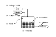
- FIG. 1 illustrates a WF 6 synthesizing apparatus used in the method of manufacturing WF 6 according to the present embodiment.
- the apparatus for synthesizing WF 6 used in the method for manufacturing WF 6 of the present embodiment is not limited to the apparatus shown in FIG.
- a WF 6 synthesis apparatus 100 includes a reaction vessel (reactor) 16 filled with a raw material tungsten 18, a hydrogen fluoride gas (HF) supply unit 13, a fluorine-containing gas supply unit 14, and not shown. It is constituted by an inert gas (N 2 ) supply device.
- a reaction vessel 16 filled with a raw material tungsten 18, a hydrogen fluoride gas (HF) supply unit 13, a fluorine-containing gas supply unit 14, and not shown. It is constituted by an inert gas (N 2 ) supply device.
- the reaction vessel 16 is provided with a jacket or an electric heater (not shown), and temperature-controlled water can flow through the jacket to adjust the temperature inside the reaction vessel 16.
- the electric heater can heat the inside of the reaction vessel 16.
- the HF gas supply unit 13 and the fluorine-containing gas supply unit 14 include a mass flow controller (not shown).
- the HF gas supply device 13 and the fluorine-containing gas supply device 14 can supply the gas into the reaction vessel 16 while adjusting the flow rates of these gases by a mass flow controller.
- the gas after the reaction can be taken out from the product outlet 17 provided at the subsequent stage of the reaction vessel 16.
- reaction vessel 16 may be provided with a circulation mechanism for circulating an F 2 gas, an inert gas, or an F 2 gas containing HF so as to circulate through the tungsten.
- Method for removing the oxide film of tungsten according to the second embodiment of the method for removing the present invention the oxide film of tungsten and tungsten with an oxide film, comprising the HF 50 ppm by volume to 50% by volume or less, F 2 gas or an This is a method of contacting with an active gas.
- the surface of tungsten is oxidized (corroded) in the atmosphere even at room temperature and normal humidity to form an oxide film, and the outermost surface is covered with the oxide film.
- the inventor of the present invention has conducted extensive studies and found that, in terms of parts per million by volume, F 2 gas containing 100 vol ppm or more and 1 vol% or less of HF with respect to F 2 gas or an inert gas is previously oxidized.
- F 2 gas containing 100 vol ppm or more and 1 vol% or less of HF with respect to F 2 gas or an inert gas is previously oxidized.
- the concentration of HF in the F 2 gas or the inert gas in the method for removing an oxide film of tungsten according to the present embodiment may be expressed in parts per million by volume or based on the combined volume of the F 2 gas or the inert gas and HF. Expressed as a percentage, it is 50 ppm by volume or more and 50% by volume or less. If the concentration of HF is less than 50 ppm by volume, the effect of removing the oxide film on the tungsten surface is small. If the concentration is more than 50% by volume, the strong oxidizing power of HF may cause corrosion of the reactor. Preferably, it is 100 vol ppm or more and 1 vol% or less.
- the contact temperature between tungsten and HF gas is preferably 25 ° C. or more and 200 ° C. or less. Even if the temperature at the time of the above-mentioned contact is room temperature (25 ° C.), the oxide film on the surface of tungsten is removed, and the tungsten is sufficiently activated. More preferably, it is 40 ° C. or higher. If the contact temperature is higher than 200 ° C., the reactor may be damaged, more preferably 150 ° C. or lower.
- the reactor only needs to be able to be filled with tungsten, and may be a batch type reactor or a continuous type reactor.
- the material of the reactor can be selected from those having resistance to F 2 , WF 6 and HF, and examples thereof include nickel, nickel alloy and stainless steel.
- nickel alloy include Monel (registered trademark) mainly composed of nickel and copper and further containing iron, manganese, sulfur, or the like.
- stainless steel austenitic stainless steel such as SUS304 or SUS316 can be used. Examples can be given.
- a method for producing WF 6 of the present invention will be described with reference to specific examples. However, the method for producing WF 6 of the present invention is not limited by the following examples.
- the reaction vessel 16 is a batch-type reaction vessel 16 having a size of Ni, an inner diameter of 55 mm, an outer diameter of 60 mm, and a length of 300 mm. Temperature-controlled water is supplied into the jacket of the reaction vessel 16 at a flow rate of 0.5 L / min. The mixture was circulated to adjust the temperature inside the reaction vessel 16.
- Example 1 [First step (pretreatment step)]
- the reaction vessel 16 is filled with a commercially available raw material tungsten 18 (605.5 g, particle size 1 ⁇ m), the inside of the reaction vessel 16 is degassed, and then warm water is passed through a jacket (not shown). Warmed to ° C. With the inside of the reaction vessel 16 kept at 70 ° C., the concentration of the HF gas with respect to the F 2 gas is set to 100 ppm by volume (0.01% by volume) and the internal pressure of the reaction vessel 16 is set to 80 kPa. HF gas and F 2 gas were supplied from the HF gas supplier 13 and the fluorine-containing gas supplier.
- FIG. 2 shows the results of the XPS analysis.
- the oxide film has been removed from the tungsten after the first step since the peaks A and B indicating the WO bond have disappeared. It was confirmed.
- Example 2 In the first step, the raw material tungsten 18 was used in the same manner as in Example 1 except that the concentration of HF in the F 2 gas charged into the reaction vessel 16 was changed to 1,000 vol ppm (0.1 vol%). Using the same conditions and procedures, the first step and then the second step were performed. In a second step, after the start of circulation, after the lapse of 20 minutes, a portion of the reaction gas from the product outlet 17 is taken out, was measured by the Fourier transform infrared spectrophotometer, WF 6 gas concentration of 99% or more Was included.
- Example 3 In the first step, the same tungsten tungsten 18 as in Example 1 was used except that the concentration of HF in the F 2 gas charged into the reaction vessel 16 was changed to 10,000 vol ppm (1 vol%). Under the same conditions and procedures, the first step and then the second step were performed. In a second step, after the start of circulation, after the lapse of 20 minutes, a portion of the reaction gas from the product outlet 17 is taken out, was measured by the Fourier transform infrared spectrophotometer, WF 6 gas concentration of 99% or more Was included.
- Example 4 [First step (pretreatment step)] The reaction vessel 16 was filled with the same raw material tungsten 18 as used in Example 1, the inside of the reaction vessel 16 was degassed, and then warm water was allowed to flow through a jacket (not shown). Was heated. With the inside of the reaction vessel 16 kept at 40 ° C., the concentration of HF with respect to the F 2 gas is 100 vol ppm (0.01 vol%) in terms of volume percentage, and the internal pressure of the reaction vessel 16 is 80 kPa. HF gas and F 2 gas were supplied from the HF gas supply unit 13 and the fluorine-containing gas supply unit 14.
- the gas inside the reaction vessel 16 was circulated so as to pass through the raw material tungsten 18, and the reaction vessel 16 was kept at 40 ° C. for 24 hours.
- the F 2 gas is supplied into the reaction vessel 16 from the fluorine-containing gas supply unit 14 at a flow rate of 0.5 slm using a mass flow controller (not shown).
- a mass flow controller not shown.
- the F 2 gas was passed through the reaction vessel 16 so as to pass through the tungsten 18 from which the oxide film filled in the reaction vessel 16 had been removed.
- Twenty minutes after the start of the circulation a part of the reaction gas was taken out from the product outlet 17 and measured by the Fourier transform infrared spectrophotometer. As a result, the concentration of WF 6 gas was 99% or more.
- Example 5 [First Step (Pretreatment Step)]
- the reaction vessel 16 was filled with the same raw material tungsten 18 as used in Example 1, the inside of the reaction vessel 16 was degassed, and then warm water was allowed to flow through a jacket (not shown). Was heated. With the inside of the reaction vessel 16 kept at 40 ° C., the concentration of HF with respect to the N 2 gas is 100 vol ppm (0.01 vol%) expressed as a volume percentage, and the internal pressure of the reaction vessel 16 is 80 kPa. Then, HF gas and N 2 gas were supplied from the HF gas supply device 13 and an N 2 gas supply device (not shown).
- the gas inside the reaction vessel 16 was circulated so as to pass through the raw material tungsten 18, and the reaction vessel 16 was kept at 40 ° C. for 24 hours.
- the F 2 gas is supplied into the reaction vessel 16 from the fluorine-containing gas supply unit 14 at a flow rate of 0.5 slm using a mass flow controller (not shown).
- a mass flow controller not shown.
- the F 2 gas was passed through the reaction vessel 16 so as to pass through the tungsten 18 from which the oxide film filled in the reaction vessel 16 had been removed.
- Twenty minutes after the start of the circulation a part of the reaction gas was taken out from the product outlet 17 and measured by the Fourier transform infrared spectrophotometer. As a result, the concentration of WF 6 gas was 99% or more.
- Example 1 In the first step, the same raw material tungsten 18 as in Example 1 was used except that the concentration of HF in the F 2 gas charged into the reaction vessel 16 was changed to 10 vol ppm (0.001 vol%). The first step and then the second step were performed under the same conditions and procedures as in Example 1. A part of the gas was taken out from the product outlet 17 and measured by the Fourier transform infrared spectrophotometer. As a result, the concentration of WF 6 was 5%.
- Example 2 Without performing the first step, the second step was performed in the same procedure as in Example 1 using the same raw material tungsten 18 as in Example 1. After 605.5 g of tungsten 18 was sealed in the reaction vessel 16 and degassed, water at 70 ° C. was passed through the jacket to keep the inside of the reaction vessel 16 at 70 ° C. While supplying F 2 gas from the fluorine-containing gas supply unit 14 at a flow rate of 0.5 slm using a mass flow controller (not shown), only the F 2 gas is charged into the reaction vessel 16 at an internal pressure of the reaction vessel 16 of 80 kPa. The raw material tungsten 18 was passed through the reaction vessel 16 so as to pass through. Twenty minutes after the start of the circulation, a part of the product gas was taken out from the product outlet 17 and measured with the Fourier transform infrared spectrophotometer. As a result, the concentration of the WF 6 gas was 3%.
- Table 1 shows that in Examples 1 to 4 and Comparative Examples 1 and 2, the contact temperature of the raw material tungsten 18 with the F 2 gas containing HF in the first step, the HF concentration in F 2 , and the second step
- the graph also shows the contact temperature between the tungsten from which the oxide film has been removed and the F 2 gas, and the concentration of WF 6 in the product gas at the product outlet 17.
- Examples 1 to 4 belonging to the method for producing WF 6 of the present invention in the second step, even though the contact temperature is 40 ° C. or 70 ° C., which is lower than the conventional one, 99% or more is finally obtained. WF 6 was obtained at high concentrations.
- Comparative Example 1 in which the HF concentration in the F 2 gas was low and was not included in the WF 6 manufacturing method of the present invention, the WF 6 concentration was 5%, which was a low concentration.
- Comparative Example 2 in which the first step in the method for producing WF 6 of the present invention was not performed, the WF 6 concentration was finally 3%, which was a low concentration.
- WF 6 can be obtained by bringing tungsten and a fluorine-containing gas into contact at a lower temperature than in the prior art. Further, by using the method for producing WF 6 or the method for removing an oxide film of tungsten according to the embodiment of the present invention, by removing the oxide film on the tungsten surface, the tungsten is activated so that it can quickly react with F 2 gas. WF 6 can be obtained by contacting tungsten with a fluorine-containing gas at a lower temperature than the method of producing WF 6 shown in the prior art, and the reactor is not damaged.
Landscapes
- Chemical & Material Sciences (AREA)
- Organic Chemistry (AREA)
- Inorganic Chemistry (AREA)
- Chemical Vapour Deposition (AREA)
- Inorganic Compounds Of Heavy Metals (AREA)
Abstract
本発明の一実施形態に係る六フッ化タングステンの製造方法は、酸化被膜を有するタングステンと、フッ化水素を50体積ppm以上50体積%以下含む、フッ素ガスまたは不活性ガスとを、反応器内で接触させ酸化被膜を除去したタングステンを得る、第1の工程と、第1の工程で酸化被膜が除去されたタングステンと、フッ素含有ガスとを接触させて、六フッ化タングステンを得る第2の工程とを含む。
Description
本発明は、六フッ化タングステンの製造方法に関する。六フッ化タングステンは、半導体製造用ガスとして、半導体基板の金属配線(回路)の形成等に用いられている。
タングステンは高融点で電気抵抗の小さい金属であり、各種電子材料用素材として金属単体あるいはそのシリサイドの形で広く使用されている。電子材料分野、特に半導体分野では、タングステンによる回路が、六フッ化タングステン(以下、WF6と呼ぶことがある)を原料ガスとし、化学気相蒸着法(Chemical Vapor Deposition、以下、CVD法と呼ぶことがある)にて、回路上に蒸着することで形成されている。WF6は、通常、金属タングステン単体(以下、単にタングステンと呼ぶことがある)とフッ素ガス(以下、F2ガスと呼ぶことがある)との反応により製造されている。
例えば、特許文献1には、単体金属とフッ素ガスとを反応させてガス状金属フッ化物を製造する方法において、該金属単体に予め成型助剤としてフッ素と反応しない固体金属フッ化物を添加または混合し、これを加圧成形した後、この成形体を加熱した状態でフッ素ガスと接触させて反応させる、ガス状金属フッ化物の製造方法が開示されている。特許文献1において、ガス状金属フッ化物としてWF6が例示され、該文献の表1に、WF6を得る場合の反応温度が250~500℃であることが記載されている。その実施例においては、タングステン粉末とフッ化ナトリウム粉末を質量比1対1で混合した後、円柱状に成形し、380~400℃に加熱した状態でフッ素ガスと接触させて得られたWF6ガスを-80℃の冷却トラップで液化して捕集したことが記載されている。
また、特許文献2には、三フッ化窒素ガス(以下、NF3と呼ぶことがある)中の水分の濃度が、1容量ppm以下であり、該NF3ガスを用い、反応器内でタングステンと200~400℃で接触させる高純度WF6の製造方法が開示されており、WF6を安定的に高純度に精製する方法について鋭意検討を重ねた結果、洗浄処理された後のNF3ガス中に微量の水分が含まれていることに着目し、この水分を限界まで除去することで、純度の高いWF6が得られることを見いだしたことが記載されている。
特許文献3には、タングステン粉とF2ガスを用いて、WF6を合成する際に金属フッ化物であるCoF3またはAgF2を触媒として使用するWF6合成方法が開示されており、WF6の合成時の温度は270~350℃であることが記載されている。
特許文献4には、タングステンとフッ素化剤とを接触反応させてWF6を製造する方法において、密閉した反応器内にタングステン粉末を投入し、ここに加圧された不活性ガスを噴射してタングステン粉末を流動化させた後、ここに加圧されたガス状フッ素化剤とタングステン粉末を連続的に供給して流動化状態で接触反応させる、流動化反応器を用いるWF6の製造方法が開示され、その際の反応温度を230℃~300℃に維持することが記載されている。
タングステンとF2ガスからWF6を生成する際の以下の反応(1)において、標準生成熱ΔHは、-1722kJ/WF6mol(298K、1atm)であり、タングステンとNF3ガスからWF6を生成する、以下の反応式(2)の標準生成熱ΔHは、-1458kJ/WF6mol(298K、1atm)である。

前記反応(1)および反応(2)の反応速度は極めて速く、WF6の生成熱量も大きいため、WF6の製造工程において、反応系の温度は急激に上昇する。反応系の温度が高温になると、金属製の反応器の内壁(以下、単に反応器壁と呼ばれることがある)がフッ素含有ガスにより侵される(腐食する)ことが知られている。
本来、タングステンは金属光沢を示す銀白色の金属であるが、大気中の酸素、または水分により、表面が酸化(腐食)され、タングステンの酸化物からなる酸化被膜が生成し徐々に光沢を失うことが知られている。しかしながら、この酸化はごく薄いもので内部までは進行しないことも知られている。タングステンの表面は、湿度の高い環境下では、ごく薄いタングステンの酸化物からなる自然酸化被膜(以下、単に酸化被膜と呼ぶことがある)が生じやすく、光沢を失いやすい。このようなタングステンの酸化物には、酸化タングステン(W2O3)、二酸化タングステン(WO2)、三酸化タングステン(WO3)が存在する。
また、特許文献5には、タングステン粉体に形成されている自然酸化被膜は、アルカリ水溶液との接触で化学的に除去できることが記載されている。
従来技術(特許文献1~4)において、タングステンとF2ガスを接触させてWF6を製造する際、200℃を超える反応温度を採用することが、奨励されている。しかしながら、前述のようにタングステンとF2ガスを反応させてWF6を得る際の反応速度は、極めて速く、生成熱量も大きいことから反応の熱暴走が懸念される。このような異常反応、金属製の反応器壁がフッ素含有ガスに侵食されること等を抑制するには、反応器のジャケットに冷媒を流通させるなどの冷却機構を設け、反応中の反応器壁の温度を400℃以下に抑える必要があった。このため、WF6の製造においては、反応開始時は加熱を必要とし、反応中は反応熱の除去のために冷却を必要とする。よって、反応器に加熱器と冷却器をともに付設することが多い。加熱器と冷却器の両方を設けた場合、反応時に加熱と冷却の切換操作も煩雑であり、加熱と冷却の切換のタイミングを間違えると、前述の通り、反応器壁の温度が上昇し過ぎて反応器が損傷する虞があった。
本発明は、これらを解決し、従来技術に比べて、低温でWF6を得ることのできるWF6の製造方法を提供することを目的とする。さらに、本発明は、反応器を傷めることのない低温でWF6を得ることのできる、WF6の製造方法、および低温で酸化被膜を除去することのできるタングステンの酸化被膜の除去方法を提供することを目的とする。
上記問題を解決するために、本発明者らが鋭意検討したところ、F2ガスに対し、体積百万分率で表してフッ化水素(以下、HFと呼ぶことがある)を濃度50体積ppm以上含むF2ガスを、あるいは、N2ガスに対し、体積百万分率で表してHFを濃度50体積ppm以上含むF2ガスを、酸化被膜を有する原料タングステンに予め接触させる前処理を行うことで、意外なことに、タングステンの表面の酸化被膜が除去され、その後、200℃以下の低温でも、タングステンがF2ガスと速やかに反応しWF6が生成することがわかり、本発明を完成するに至った(後述の実施例の[表1]参照)。
本発明は、以下の態様1~6を含む。
[態様1]
酸化被膜を有するタングステンと、フッ化水素を50体積ppm以上50体積%以下含む、フッ素ガスまたは不活性ガスとを、反応器内で接触させ、酸化被膜を除去したタングステンを得る、第1の工程と、第1の工程で酸化被膜が除去されたタングステンと、フッ素含有ガスと、を、反応器内で接触させて、六フッ化タングステンを得る第2の工程と、を含む、六フッ化タングステンの製造方法。
[態様2]
前記第1の工程において、酸化被膜を有するタングステンと、フッ化水素を50体積ppm以上50体積%以下含む、フッ素ガスまたは不活性ガスとを、25℃以上200℃以下で接触させる、態様1の六フッ化タングステンの製造方法。
[態様3]
前記第2の工程に用いるフッ素含有ガスがフッ素ガス、三フッ化窒素ガス、またはこれらの混合ガスである、態様1または態様2の六フッ化タングステンの製造方法。
[態様4]
前記第2の工程において、酸化被膜を除去したタングステンと、フッ素含有ガスとを、25℃以上200℃以下で接触させる、態様1~3の六フッ化タングステンの製造方法。
[態様5]
酸化被膜を有するタングステンと、フッ化水素ガスを50体積ppm以上1体積%以下含む、フッ素ガスまたは不活性ガスを接触させる、タングステンの酸化被膜の除去方法。
[態様6]
酸化被膜を有するタングステンと、フッ化水素ガスを50体積ppm以上1体積%以下含む、フッ素ガスまたは不活性ガスとを、25℃以上200℃以下で接触させる、態様5のタングステンの酸化被膜の除去方法。
[態様1]
酸化被膜を有するタングステンと、フッ化水素を50体積ppm以上50体積%以下含む、フッ素ガスまたは不活性ガスとを、反応器内で接触させ、酸化被膜を除去したタングステンを得る、第1の工程と、第1の工程で酸化被膜が除去されたタングステンと、フッ素含有ガスと、を、反応器内で接触させて、六フッ化タングステンを得る第2の工程と、を含む、六フッ化タングステンの製造方法。
[態様2]
前記第1の工程において、酸化被膜を有するタングステンと、フッ化水素を50体積ppm以上50体積%以下含む、フッ素ガスまたは不活性ガスとを、25℃以上200℃以下で接触させる、態様1の六フッ化タングステンの製造方法。
[態様3]
前記第2の工程に用いるフッ素含有ガスがフッ素ガス、三フッ化窒素ガス、またはこれらの混合ガスである、態様1または態様2の六フッ化タングステンの製造方法。
[態様4]
前記第2の工程において、酸化被膜を除去したタングステンと、フッ素含有ガスとを、25℃以上200℃以下で接触させる、態様1~3の六フッ化タングステンの製造方法。
[態様5]
酸化被膜を有するタングステンと、フッ化水素ガスを50体積ppm以上1体積%以下含む、フッ素ガスまたは不活性ガスを接触させる、タングステンの酸化被膜の除去方法。
[態様6]
酸化被膜を有するタングステンと、フッ化水素ガスを50体積ppm以上1体積%以下含む、フッ素ガスまたは不活性ガスとを、25℃以上200℃以下で接触させる、態様5のタングステンの酸化被膜の除去方法。
本発明の実施形態を、詳細に説明する。しかしながら、本発明は、以下に示す実施の形態に限定されるものではない。
本発明の第一の実施形態に係るWF6の製造方法は、酸化被膜を有するタングステンと、HFを50体積ppm以上50体積%以下含む、F2ガスまたは不活性ガスとを、反応器内で接触させ、酸化被膜を除去したタングステンを得る、第1の工程(以下、前処理工程ということがある)と、第1の工程で酸化被膜が除去されたタングステンと、フッ素含有ガスと接触させて、WF6を得る第2の工程と、を含む。
尚、第1の工程は、後述する本発明の第二の実施形態に係るタングステンの酸化被膜の除去方法に相当する。
尚、第1の工程は、後述する本発明の第二の実施形態に係るタングステンの酸化被膜の除去方法に相当する。
1.原料タングステン
なお、六フッ化タングステンの製造方法の原料である金属タングステン(以下、原料タングステンと呼ぶことがある)は市販されており、インゴットまたは粉体状に加工されたものを購入することができる。空気中でタングステン粉の最表面はごく薄く酸化され、市販の粉は、この自然酸化被膜の形成により、光沢を失い褐色を呈する。六フッ化タングステンの製造方法において、原料タングステンは、「酸化被膜を有するタングステン」と呼び変えることができる。
なお、六フッ化タングステンの製造方法の原料である金属タングステン(以下、原料タングステンと呼ぶことがある)は市販されており、インゴットまたは粉体状に加工されたものを購入することができる。空気中でタングステン粉の最表面はごく薄く酸化され、市販の粉は、この自然酸化被膜の形成により、光沢を失い褐色を呈する。六フッ化タングステンの製造方法において、原料タングステンは、「酸化被膜を有するタングステン」と呼び変えることができる。
六フッ化タングステンの製造方法において、原料タングステンには、粉体、塊、インゴット等の種々の形状の物を用いることが可能である。六フッ化タングステンの製造方法に用いる、原料タングステンは、100nm以下の粉体、10cm以上のインゴット等の様々な形状から選択することが可能であるが、反応容器へ原料タングステンを充填する際の容易さ、およびタングステンの粉体および塊に対するF2ガスまたは不活性ガスの流通のし易さから、粒度1μm以上10cm以下の粉体または塊を使用することが好ましい。また、粒度0.5μm~1500μmの範囲で種々の粒度の粉状および粒状タングステンが市販され、これら市販品の中から任意に選択して用いることも好ましい。なお、本発明において、タングステン粉の粒度はFisher Sub-Sieve Sizer法による平均粒子径である。
タングステンの酸化被膜の除去方法においても、上記の原料タングステンを任意に選択して用いることができる。
2.第1の工程(前処理工程)
本実施形態のWF6の製造方法の第1の工程は、酸化被膜を有するタングステン(原料タングステン)と、HFを50体積ppm以上50体積%以下含む、F2ガスまたは不活性ガス(以下、「HF含有ガス」とも称する)とを、反応器内で接触させ酸化被膜を除去したタングステンを得る工程である。不活性ガスとしては、窒素(N2)、ヘリウム(He)、またはアルゴン(Ar)を挙げることができるが、入手の容易および価格より、好ましくはN2である。
本実施形態のWF6の製造方法の第1の工程は、酸化被膜を有するタングステン(原料タングステン)と、HFを50体積ppm以上50体積%以下含む、F2ガスまたは不活性ガス(以下、「HF含有ガス」とも称する)とを、反応器内で接触させ酸化被膜を除去したタングステンを得る工程である。不活性ガスとしては、窒素(N2)、ヘリウム(He)、またはアルゴン(Ar)を挙げることができるが、入手の容易および価格より、好ましくはN2である。
前述のように、タングステンは、大気中では常温常湿においても表面が腐食され酸化被膜を生成し、最表面が酸化被膜で覆われることが知られている。最表面が酸化被膜で覆われたタングステンはF2との反応性に劣るため、特許文献1~4に記載の様に、200℃を超える高温下でF2ガスを接触させて反応させ、WF6を製造しなければならないこととなる。
しかしながら、本発明者が鋭意検討した所、体積百万分率で表して、F2ガスまたは不活性ガスに対し、HFを濃度50体積ppm以上50体積%以下含む、F2ガスまたは不活性ガスを、予め原料タングステンに接触させておく前処理工程(第1の工程)を加えることで、意外なことに、別途、特許文献5に記載のアルカリ処理等行うことなく、原料タングステンの表面は酸化被膜が除去され活性化し、150℃以下の低温でもタングステンがF2ガスと速やかに反応し、WF6が速やかに生成することが分かった([表1]の実施例1~5参照)。
後述の通り、実施例において、酸化被膜を除去するためのアルカリ処理等は、原料タングステンに対し何ら行っていない。前記WF6を合成する前の前処理において、F2ガスに、低濃度であってもHFが含まれることで、HFは反応器壁を腐食させることなく、タングステン最表面の酸化被膜を除去することが可能であり、タングステン表面の酸化被膜を除去することで、タングステンの表面がF2ガスと速やかに反応する様に活性化し、WF6がより低温で速やかに生成することを可能としたと推測される。
後述の通り、実施例において、酸化被膜を除去するためのアルカリ処理等は、原料タングステンに対し何ら行っていない。前記WF6を合成する前の前処理において、F2ガスに、低濃度であってもHFが含まれることで、HFは反応器壁を腐食させることなく、タングステン最表面の酸化被膜を除去することが可能であり、タングステン表面の酸化被膜を除去することで、タングステンの表面がF2ガスと速やかに反応する様に活性化し、WF6がより低温で速やかに生成することを可能としたと推測される。
本実施形態の六フッ化タングステンの製造方法において、原料タングステンとHF含有ガスが接触した第1の工程後の反応系には、WOF4またはWF6が検出される。このことから、原料タングステンとHF含有ガスが接触することで、原料タングステンから酸化被膜が除去される機構として、以下の反応を推測することができる。
例えば、三酸化タングステン(WO3)と、HFは、以下の反応(3)~(6)の様に反応し、WO3よりWOF4が生成されたと推測される。
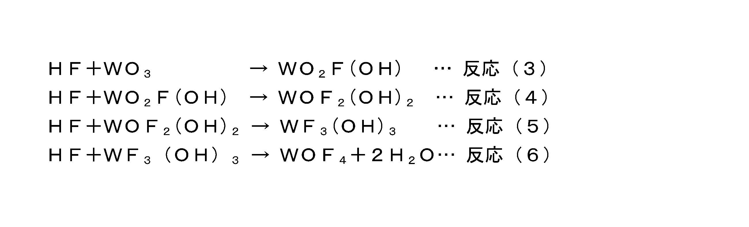
F2ガスの存在下では、反応(5)で生成したWF3(OH)3と、F2ガスが、以下の式(7)のように反応し、結果として、WO3よりWF6が生成されたと推測される。

反応(6)より得られたWOF4、反応(7)より得られたWF6は気化することにより反応系に留まる。このようにして、タングステンの酸化被膜は気体(WOF4またはWF6)となり、タングステン表面から除去されたものと推測される。
例えば、三酸化タングステン(WO3)と、HFは、以下の反応(3)~(6)の様に反応し、WO3よりWOF4が生成されたと推測される。
本実施形態のWF6の製造方法の第1の工程におけるF2ガスまたは不活性ガス中のHFの濃度は、F2ガスとHFを合わせた体積、または不活性ガスとHFを合わせた体積を基準とする体積百万分率または百分率で表して、50体積ppm以上50体積%以下である。HFの濃度が50体積ppmより少ないと、原料タングステン表面の酸化被膜を除去する効果が少なく、50体積%より多いと、HFにより反応器壁が腐食する懸念がある。好ましくは、100体積ppm以上1体積%(10,000体積ppm)以下である。
[接触温度]
本発明のWF6の製造方法の第1の工程における原料タングステンとHF含有ガスとの接触温度は、25℃以上200℃以下であることが好ましい。上記の接触の際の温度が室温(25℃)であっても、原料タングステンの表面は酸化被膜が除去され充分に活性化する。より好ましくは40℃以上である。本発明のWF6の製造方法の目的は、反応器、特に反応器壁を傷めないよう、200℃を超える反応温度を用いることなくWF6の製造することなので、タングステンとHF含有ガスとを接触させる際の温度を200℃より高くする必要はなく、より好ましくは150℃以下である。特に好ましくは、70℃以下である。
本発明のWF6の製造方法の第1の工程における原料タングステンとHF含有ガスとの接触温度は、25℃以上200℃以下であることが好ましい。上記の接触の際の温度が室温(25℃)であっても、原料タングステンの表面は酸化被膜が除去され充分に活性化する。より好ましくは40℃以上である。本発明のWF6の製造方法の目的は、反応器、特に反応器壁を傷めないよう、200℃を超える反応温度を用いることなくWF6の製造することなので、タングステンとHF含有ガスとを接触させる際の温度を200℃より高くする必要はなく、より好ましくは150℃以下である。特に好ましくは、70℃以下である。
[接触時間]
本実施形態のWF6の製造方法の第1の工程における原料タングステンとHF含有ガスとを接触させる際の接触時間は、例えば、原料タングステン表面の酸化の進行の程度、第2の工程後のWF6の収率等により、任意に定めることができる。
本実施形態のWF6の製造方法の第1の工程における原料タングステンとHF含有ガスとを接触させる際の接触時間は、例えば、原料タングステン表面の酸化の進行の程度、第2の工程後のWF6の収率等により、任意に定めることができる。
[接触圧力]
本実施形態のWF6の製造方法の第1の工程における反応器内の圧力が絶対圧で0.01kPa以上300kPa以下であることが好ましく、絶対圧で0.01kPa以上100kPa以下であることがより好ましい。絶対圧の値が0.01kPa未満では、圧力を保持するための設備の負荷が大きくなるため、好ましくない。300kPa以上では、WF6が液化する可能性がある上に、装置からWF6が漏えいする虞があるため好ましくない。
本実施形態のWF6の製造方法の第1の工程における反応器内の圧力が絶対圧で0.01kPa以上300kPa以下であることが好ましく、絶対圧で0.01kPa以上100kPa以下であることがより好ましい。絶対圧の値が0.01kPa未満では、圧力を保持するための設備の負荷が大きくなるため、好ましくない。300kPa以上では、WF6が液化する可能性がある上に、装置からWF6が漏えいする虞があるため好ましくない。
3.第2の工程(以下、反応工程ということがある)
第2の工程は、第1の工程で酸化被膜を除去したタングステンとF2ガスを接触させ、WF6を得る工程である。
第2の工程は、第1の工程で酸化被膜を除去したタングステンとF2ガスを接触させ、WF6を得る工程である。
[フッ素含有ガス]
第2の工程において使用するフッ素含有ガスは、F2ガス、NF3ガス、またはこれらの混合ガスを例示することができ、N2、HeおよびArからなる群から選ばれる不活性ガスで希釈されていてもよい。好ましくは、F2ガスである。
第2の工程において使用するフッ素含有ガスは、F2ガス、NF3ガス、またはこれらの混合ガスを例示することができ、N2、HeおよびArからなる群から選ばれる不活性ガスで希釈されていてもよい。好ましくは、F2ガスである。
[反応]
第2の工程では、フッ素含有ガスがF2ガスである場合、前記反応式(1)のように、第1の工程後の(酸化被膜が除去された)タングステンと、F2ガスとが反応して、WF6が生成され、フッ素含有ガスがNF3ガスである場合、前記反応式(2)のように、第1の工程後の(酸化被膜が除去された)タングステンと、NF3ガスとが反応して、WF6が生成される。
第2の工程では、フッ素含有ガスがF2ガスである場合、前記反応式(1)のように、第1の工程後の(酸化被膜が除去された)タングステンと、F2ガスとが反応して、WF6が生成され、フッ素含有ガスがNF3ガスである場合、前記反応式(2)のように、第1の工程後の(酸化被膜が除去された)タングステンと、NF3ガスとが反応して、WF6が生成される。
[接触温度]
第2の工程において、第1の工程で酸化被膜が除去されたタングステンとフッ素含有ガスとを接触させる際の温度は、25℃以上200℃以下であることが好ましい。上記の接触の際の温度が室温(25℃)であっても、酸化被膜が除去されたタングステンは、フッ素含有ガスと反応する。より好ましくは40℃以上である。本発明のWF6の製造方法の目的は、200℃以下の低温でWF6を製造することなので、酸化被膜が除去されたタングステンとフッ素含有ガスとの接触温度を200℃より高くする必要はなく、より好ましくは150℃以下である。特に好ましくは、70℃以下である。
第2の工程において、第1の工程で酸化被膜が除去されたタングステンとフッ素含有ガスとを接触させる際の温度は、25℃以上200℃以下であることが好ましい。上記の接触の際の温度が室温(25℃)であっても、酸化被膜が除去されたタングステンは、フッ素含有ガスと反応する。より好ましくは40℃以上である。本発明のWF6の製造方法の目的は、200℃以下の低温でWF6を製造することなので、酸化被膜が除去されたタングステンとフッ素含有ガスとの接触温度を200℃より高くする必要はなく、より好ましくは150℃以下である。特に好ましくは、70℃以下である。
[接触時間]
第2の工程において、酸化被膜が除去されたタングステンとフッ素含有ガスとを接触させる際の接触時間は、例えば、WF6の収率等により任意に定めることができる。
第2の工程において、酸化被膜が除去されたタングステンとフッ素含有ガスとを接触させる際の接触時間は、例えば、WF6の収率等により任意に定めることができる。
[接触圧力]
本実施形態のWF6の製造方法の第2の工程における反応器内の好ましい圧力範囲は、上記の第1の工程における反応器内の圧力範囲と同じである。
本実施形態のWF6の製造方法の第2の工程における反応器内の好ましい圧力範囲は、上記の第1の工程における反応器内の圧力範囲と同じである。
4.WF6の製造
[反応器]
本実施形態のWF6の製造方法に用いる反応器はタングステンを充填することができればよく、バッチ式反応器でも連続式でもよい。反応器の材質はF2、WF6およびHFに耐性のあるものから選ぶことができ、ニッケル、ニッケル合金およびステンレス鋼を挙げることができる。ニッケル合金としては、主にニッケルと銅からなり、他に鉄、マンガンまたは硫黄等を含むモネル(登録商標)を例示することができ、ステンレス鋼としては、SUS304、SUS316等のオーステナイト系ステンレス鋼を例示することができる。
[反応器]
本実施形態のWF6の製造方法に用いる反応器はタングステンを充填することができればよく、バッチ式反応器でも連続式でもよい。反応器の材質はF2、WF6およびHFに耐性のあるものから選ぶことができ、ニッケル、ニッケル合金およびステンレス鋼を挙げることができる。ニッケル合金としては、主にニッケルと銅からなり、他に鉄、マンガンまたは硫黄等を含むモネル(登録商標)を例示することができ、ステンレス鋼としては、SUS304、SUS316等のオーステナイト系ステンレス鋼を例示することができる。
本実施形態のWF6の製造方法において、第1の工程におけるHF含有ガスと原料タングステン、第2の工程おけるF2ガスとタングステンの接触効率を向上させるためには、タングステン内にガスを流通させるための循環機構を設けることが好ましい。しかしながら、第1の工程においては、循環機構を設けずともタングステンの酸化被膜の除去は可能である。
[第1の工程から第2の工程への移行]
本実施形態のWF6の製造方法における、「第1の工程」(前処理工程)から「第2の工程」(反応工程)の移行について説明する。
本実施形態のWF6の製造方法における、「第1の工程」(前処理工程)から「第2の工程」(反応工程)の移行について説明する。
上記第1の工程および第2の工程は別の反応器で行ってもよいが、同じ反応器を用い連続的に行う方が簡便であり、経済的である。第1の工程から第2の工程への移行において、第1の工程後のガス中のHFの濃度が高い場合は、第1の工程後のガスを反応器から除去することが好ましい。第1の工程後のガス中のHFの濃度が低い、または第1の工程でHFが完全に消費され存在しない場合は、第1の工程後のガスを除去することなく反応器にF2ガスを供給し、第2の工程を開始してもよい。
第1の工程は、反応器に原料タングステンとHF含有ガスを充填後、密閉して行うことが好ましく、その方が簡便である。原料タングステン表面の酸化被膜を除去し活性化させるためには、反応器内部のガスを循環させ流動させておくことが好ましい。
第2の工程は、F2ガスを供給しつつ、反応器内に充填したタングステンを通過させるように流通させタングステンに接触させ、接触後のガスを採取することが簡便である。
採取したガスをフーリエ変換赤外光分光光度計で分析することにより、接触後のガス中の生成したWF6の濃度を測定することができる。
[WF6の合成装置]
本実施形態のWF6の製造方法に用いる、WF6の合成装置を図1に例示する。本実施形態のWF6の製造方法に用いる、WF6の合成装置は図1に示す装置に限定されるものではない。
本実施形態のWF6の製造方法に用いる、WF6の合成装置を図1に例示する。本実施形態のWF6の製造方法に用いる、WF6の合成装置は図1に示す装置に限定されるものではない。
図1に示す様に、WF6合成装置100は、原料タングステン18を充填した反応容器(反応器)16、フッ化水素ガス(HF)供給器13、およびフッ素含有ガス供給器14、および図示しない不活性ガス(N2)供給器により構成される。
反応容器16は、図示しないジャケットまたは電気ヒーターを備え、ジャケット内には温調した水を流通させ、反応容器16内の温度を調整することができる。電気ヒーターは、反応容器16内を加熱することができる。
HFガス供給器13およびフッ素含有ガス供給器14は、図示しないマスフローコントローラーを備える。HFガス供給器13およびフッ素含有ガス供給器14は、これらのガスの流量をマスフローコントローラーにより調整しつつ、反応容器16内に供給することができる。反応後のガスは、反応容器16の後段に設置された生成物取出口17より取り出すことができる。
また、反応容器16は、タングステンを通して流通させるように、HFを含む、F2ガスまたは不活性ガス、またはF2ガスを循環させる循環機構を設けてもよい。
5.タングステンの酸化被膜の除去方法
本発明の第二の実施形態に係るタングステンの酸化被膜の除去方法は、酸化被膜を有するタングステンと、HFを50体積ppm以上50体積%以下含む、F2ガスまたは不活性ガスとを接触させる方法である。
本発明の第二の実施形態に係るタングステンの酸化被膜の除去方法は、酸化被膜を有するタングステンと、HFを50体積ppm以上50体積%以下含む、F2ガスまたは不活性ガスとを接触させる方法である。
前述のように、タングステンは、大気中では常温常湿においても表面が酸化(腐食)され酸化被膜を生成し、最表面が酸化被膜で覆われることが知られている。しかしながら、本発明者が鋭意検討した所、体積百万分率で表して、F2ガスまたは不活性ガスに対し、HFを濃度100体積ppm以上1体積%以下含むF2ガスを、予め酸化膜を有するタングステンに接触させておく前処理工程(第1の工程)を加えることで、タングステン表面の酸化被膜が除去され、F2ガスに対して活性になり、150℃以下の低温でもタングステンがF2ガスと速やかに反応し、WF6が速やかに生成することが分かった([表1]の実施例1~4参照)。すなわち、接触温度150℃以下の温和な条件で、タングステンの最表面に生成した酸化被膜を除去することができた。
本実施形態のタングステンの酸化被膜の除去方法におけるF2ガスまたは不活性ガス中のHFの濃度は、F2ガスまたは不活性ガスと、HFを合わせた体積を基準とする体積百万分率または百分率で表して、50体積ppm以上50体積%以下である。HFの濃度が50体積ppmより少ないと、タングステン表面の酸化被膜を除去する効果が少なく、50体積%より多いと、HFの強い酸化力により反応器が腐食する懸念がある。好ましくは、100体積ppm以上1体積%以下である。
[接触温度]
本実施形態のタングステンの酸化被膜の除去方法において、タングステンとHFガスとの接触温度は、25℃以上200℃以下であることが好ましい。上記の接触の際の温度が室温(25℃)であっても、タングステンの表面の酸化被膜は除去され、タングステンは充分に活性化する。より好ましくは、40℃以上である。接触温度を200℃より高くすると反応器を傷める虞があり、より好ましくは150℃以下である。
本実施形態のタングステンの酸化被膜の除去方法において、タングステンとHFガスとの接触温度は、25℃以上200℃以下であることが好ましい。上記の接触の際の温度が室温(25℃)であっても、タングステンの表面の酸化被膜は除去され、タングステンは充分に活性化する。より好ましくは、40℃以上である。接触温度を200℃より高くすると反応器を傷める虞があり、より好ましくは150℃以下である。
[反応器]
反応器はタングステンを充填することができればよく、バッチ式反応器でも連続式でもよい。反応器の材質はF2、WF6およびHFに耐性のあるものから選ぶことができ、ニッケル、ニッケル合金およびステンレス鋼を挙げることができる。ニッケル合金としては、主にニッケルと銅からなり、他に鉄、マンガンまたは硫黄等を含むモネル(登録商標)を例示することができ、ステンレス鋼としては、SUS304、SUS316等のオーステナイト系ステンレス鋼を例示することができる。
反応器はタングステンを充填することができればよく、バッチ式反応器でも連続式でもよい。反応器の材質はF2、WF6およびHFに耐性のあるものから選ぶことができ、ニッケル、ニッケル合金およびステンレス鋼を挙げることができる。ニッケル合金としては、主にニッケルと銅からなり、他に鉄、マンガンまたは硫黄等を含むモネル(登録商標)を例示することができ、ステンレス鋼としては、SUS304、SUS316等のオーステナイト系ステンレス鋼を例示することができる。
具体的な実施例により、本発明のWF6の製造方法を説明する。しかしながら、本発明のWF6の製造方法は、以下の実施例により限定されるものではない。
[WF6合成装置]
以下の実施例では、上記図1に示したWF6合成装置100を用いてWF6の合成を行った。反応容器16は、Ni製の大きさ、内径55mm、外径60mm、長さ300mmのバッチ式反応容器16であり、反応容器16のジャケット内には温調した水を流量0.5L/minで流通させ、反応容器16内の温度を調整した。
以下の実施例では、上記図1に示したWF6合成装置100を用いてWF6の合成を行った。反応容器16は、Ni製の大きさ、内径55mm、外径60mm、長さ300mmのバッチ式反応容器16であり、反応容器16のジャケット内には温調した水を流量0.5L/minで流通させ、反応容器16内の温度を調整した。
[WF6の濃度測定]
生成物取出口17より取り出したガス中のWF6の濃度は、フーリエ変換赤外光分光光度計(株式会社島津製作所製、型式IRPrestage21)により、測定した。
生成物取出口17より取り出したガス中のWF6の濃度は、フーリエ変換赤外光分光光度計(株式会社島津製作所製、型式IRPrestage21)により、測定した。
[実施例1]
[第1の工程(前処理工程)]
反応容器16内に、市販の原料タングステン18(605.5g、粒度1μm)を充填し、反応容器16内を脱気し、次いで、温水を図示しないジャケットに流通させて、反応容器16内を70℃に加温した。反応容器16内を70℃に保った状態で、F2ガスに対し、HFガスの濃度が、100体積ppm(0.01体積%)、且つ、反応容器16の内圧が80kPaになるように、HFガス供給器13およびフッ素含有ガス供給器14からHFガスとF2ガスを供給した。供給後、反応容器16内を70℃に保った状態で、原料タングステン18を通過するように、循環機構を用いて、反応器内16のガスを循環させつつ、24時間経過させた。反応容器16内のガスを抜き出し、不活性ガス(N2)で置換した後、反応容器16内のタングステンの一部を抜出しXPS(X-ray Photoelectron Spectroscopy:X線電子分光法)分析を行った。図2にXPS分析の結果を示す。W-O結合のピークA、Bを有する原料タングステンに対し、第1の工程後のタングステンはW-O結合を示すピークA、Bが消失していることから、酸化被膜が除去されていることを確認した。
[第2の工程(反応工程)]
続いて、反応容器16内を70℃に保った状態で、反応容器16内にF2ガスを、フッ素含有ガス供給器14より、図示しないマスフローコントローラーを用いて流量、0.5slm(0℃、1atmにおける1分間辺りのリットルで表される流量)で供給しつつ、反応容器16の内圧80kPaにて、F2ガスのみを、反応容器16に充填した酸化被膜を除去したタングステン18を通過するように、反応容器16に流通させた。流通開始後、20分経過した後、生成物取出口17から反応ガスの一部を取り出し、前記フーリエ変換赤外分光光度計で測定したところ、WF6ガスが濃度99%以上含まれていた。
[第1の工程(前処理工程)]
反応容器16内に、市販の原料タングステン18(605.5g、粒度1μm)を充填し、反応容器16内を脱気し、次いで、温水を図示しないジャケットに流通させて、反応容器16内を70℃に加温した。反応容器16内を70℃に保った状態で、F2ガスに対し、HFガスの濃度が、100体積ppm(0.01体積%)、且つ、反応容器16の内圧が80kPaになるように、HFガス供給器13およびフッ素含有ガス供給器14からHFガスとF2ガスを供給した。供給後、反応容器16内を70℃に保った状態で、原料タングステン18を通過するように、循環機構を用いて、反応器内16のガスを循環させつつ、24時間経過させた。反応容器16内のガスを抜き出し、不活性ガス(N2)で置換した後、反応容器16内のタングステンの一部を抜出しXPS(X-ray Photoelectron Spectroscopy:X線電子分光法)分析を行った。図2にXPS分析の結果を示す。W-O結合のピークA、Bを有する原料タングステンに対し、第1の工程後のタングステンはW-O結合を示すピークA、Bが消失していることから、酸化被膜が除去されていることを確認した。
[第2の工程(反応工程)]
続いて、反応容器16内を70℃に保った状態で、反応容器16内にF2ガスを、フッ素含有ガス供給器14より、図示しないマスフローコントローラーを用いて流量、0.5slm(0℃、1atmにおける1分間辺りのリットルで表される流量)で供給しつつ、反応容器16の内圧80kPaにて、F2ガスのみを、反応容器16に充填した酸化被膜を除去したタングステン18を通過するように、反応容器16に流通させた。流通開始後、20分経過した後、生成物取出口17から反応ガスの一部を取り出し、前記フーリエ変換赤外分光光度計で測定したところ、WF6ガスが濃度99%以上含まれていた。
[実施例2]
第1の工程において、反応容器16に充填するF2ガス中のHFの濃度を、1,000体積ppm(0.1体積%)に変えた以外は、実施例1と同じ、原料タングステン18を用い、同様の条件および手順で、第1の工程、次いで第2の工程を行った。第2工程において、流通開始後、20分経過した後、生成物取出口17から反応ガスの一部を取り出し、前記フーリエ変換赤外分光光度計で測定したところ、WF6ガスが濃度99%以上含まれていた。
第1の工程において、反応容器16に充填するF2ガス中のHFの濃度を、1,000体積ppm(0.1体積%)に変えた以外は、実施例1と同じ、原料タングステン18を用い、同様の条件および手順で、第1の工程、次いで第2の工程を行った。第2工程において、流通開始後、20分経過した後、生成物取出口17から反応ガスの一部を取り出し、前記フーリエ変換赤外分光光度計で測定したところ、WF6ガスが濃度99%以上含まれていた。
[実施例3]
第1の工程において、反応容器16に充填するF2ガス中のHFの濃度を、10,000体積ppm(1体積%)に変えた以外は、実施例1と同じ、原料タングステン18を用い、同様の条件および手順で、第1の工程、次いで第2の工程を行った。第2工程において、流通開始後、20分経過した後、生成物取出口17から反応ガスの一部を取り出し、前記フーリエ変換赤外分光光度計で測定したところ、WF6ガスが濃度99%以上含まれていた。
第1の工程において、反応容器16に充填するF2ガス中のHFの濃度を、10,000体積ppm(1体積%)に変えた以外は、実施例1と同じ、原料タングステン18を用い、同様の条件および手順で、第1の工程、次いで第2の工程を行った。第2工程において、流通開始後、20分経過した後、生成物取出口17から反応ガスの一部を取り出し、前記フーリエ変換赤外分光光度計で測定したところ、WF6ガスが濃度99%以上含まれていた。
[実施例4]
[第1の工程(前処理工程)]
反応容器16内に、実施例1で用いたのと同じ原料タングステン18を充填し、反応容器16内を脱気し、次いで、温水を図示しないジャケットに流通させて、反応容器16内を40℃に加温した。反応容器16内を40℃に保った状態で、F2ガスに対するHFの濃度が、体積百分率で表して100体積ppm(0.01体積%)、且つ、反応容器16の内圧が80kPaになるように、HFガス供給器13およびフッ素含有ガス供給器14からHFガスとF2ガスを供給した。供給後、原料タングステン18を通過するように、反応容器内16のガスを循環させつつ、反応容器16内を40℃に保った状態で24時間経過させた。
[第2の工程(反応工程)]
続いて、反応容器16内を40℃に保った状態で、反応容器16内にF2ガスを、フッ素含有ガス供給器14より、図示しないマスフローコントローラーを用いて流量、0.5slmで供給しつつ、反応容器16の内圧80kPaにて、F2ガスのみを、反応容器16に充填した酸化被膜を除去したタングステン18を通過するように、反応容器16に流通させた。流通開始後、20分経過した後、生成物取出口17から反応ガスの一部を取り出し、前記フーリエ変換赤外分光光度計で測定したところ、WF6ガスが濃度99%以上含まれていた。
[第1の工程(前処理工程)]
反応容器16内に、実施例1で用いたのと同じ原料タングステン18を充填し、反応容器16内を脱気し、次いで、温水を図示しないジャケットに流通させて、反応容器16内を40℃に加温した。反応容器16内を40℃に保った状態で、F2ガスに対するHFの濃度が、体積百分率で表して100体積ppm(0.01体積%)、且つ、反応容器16の内圧が80kPaになるように、HFガス供給器13およびフッ素含有ガス供給器14からHFガスとF2ガスを供給した。供給後、原料タングステン18を通過するように、反応容器内16のガスを循環させつつ、反応容器16内を40℃に保った状態で24時間経過させた。
[第2の工程(反応工程)]
続いて、反応容器16内を40℃に保った状態で、反応容器16内にF2ガスを、フッ素含有ガス供給器14より、図示しないマスフローコントローラーを用いて流量、0.5slmで供給しつつ、反応容器16の内圧80kPaにて、F2ガスのみを、反応容器16に充填した酸化被膜を除去したタングステン18を通過するように、反応容器16に流通させた。流通開始後、20分経過した後、生成物取出口17から反応ガスの一部を取り出し、前記フーリエ変換赤外分光光度計で測定したところ、WF6ガスが濃度99%以上含まれていた。
[実施例5]
[第1の工程(前処理工程)]
反応容器16内に、実施例1で用いたのと同じ原料タングステン18を充填し、反応容器16内を脱気し、次いで、温水を図示しないジャケットに流通させて、反応容器16内を40℃に加温した。反応容器16内を40℃に保った状態で、N2ガスに対するHFの濃度が、体積百分率で表して100体積ppm(0.01体積%)、且つ、反応容器16の内圧が80kPaになるように、HFガス供給器13および図示しないN2ガス供給器からHFガスとN2ガスを供給した。供給後、原料タングステン18を通過するように、反応容器内16のガスを循環させつつ、反応容器16内を40℃に保った状態で24時間経過させた。
[第2の工程(反応工程)]
続いて、反応容器16内を40℃に保った状態で、反応容器16内にF2ガスを、フッ素含有ガス供給器14より、図示しないマスフローコントローラーを用いて流量、0.5slmで供給しつつ、反応容器16の内圧80kPaにて、F2ガスのみを、反応容器16に充填した酸化被膜を除去したタングステン18を通過するように、反応容器16に流通させた。流通開始後、20分経過した後、生成物取出口17から反応ガスの一部を取り出し、前記フーリエ変換赤外分光光度計で測定したところ、WF6ガスが濃度99%以上含まれていた。
[第1の工程(前処理工程)]
反応容器16内に、実施例1で用いたのと同じ原料タングステン18を充填し、反応容器16内を脱気し、次いで、温水を図示しないジャケットに流通させて、反応容器16内を40℃に加温した。反応容器16内を40℃に保った状態で、N2ガスに対するHFの濃度が、体積百分率で表して100体積ppm(0.01体積%)、且つ、反応容器16の内圧が80kPaになるように、HFガス供給器13および図示しないN2ガス供給器からHFガスとN2ガスを供給した。供給後、原料タングステン18を通過するように、反応容器内16のガスを循環させつつ、反応容器16内を40℃に保った状態で24時間経過させた。
[第2の工程(反応工程)]
続いて、反応容器16内を40℃に保った状態で、反応容器16内にF2ガスを、フッ素含有ガス供給器14より、図示しないマスフローコントローラーを用いて流量、0.5slmで供給しつつ、反応容器16の内圧80kPaにて、F2ガスのみを、反応容器16に充填した酸化被膜を除去したタングステン18を通過するように、反応容器16に流通させた。流通開始後、20分経過した後、生成物取出口17から反応ガスの一部を取り出し、前記フーリエ変換赤外分光光度計で測定したところ、WF6ガスが濃度99%以上含まれていた。
[比較例1]
第1の工程において、反応容器16に充填するF2ガス中のHFの濃度を、10体積ppm(0.001体積%)に変えた以外は、実施例1と同じ、原料タングステン18を用い、実施例1と同様の条件および手順で、第1の工程、次いで第2の工程を行った。生成物取出口17からガスの一部を取り出し、前記フーリエ変換赤外分光光度計で測定したところ、WF6の濃度は5%であった。
第1の工程において、反応容器16に充填するF2ガス中のHFの濃度を、10体積ppm(0.001体積%)に変えた以外は、実施例1と同じ、原料タングステン18を用い、実施例1と同様の条件および手順で、第1の工程、次いで第2の工程を行った。生成物取出口17からガスの一部を取り出し、前記フーリエ変換赤外分光光度計で測定したところ、WF6の濃度は5%であった。
[比較例2]
第1の工程を行うことなしに、実施例1と同じ、原料タングステン18を用い、実施例1と同様の手順で第2の工程を行った。
反応容器16内に原料タングステン18、605.5gを封入し、脱気した後、ジャケットに70℃の水を流通させて、反応容器16内を70℃に保った状態で、反応容器16内にF2ガスを、フッ素含有ガス供給器14より、図示しないマスフローコントローラーを用いて流量、0.5slmで供給しつつ、反応容器16の内圧80kPaにて、F2ガスのみを、反応容器16に充填した原料タングステン18を通過するように、反応容器16に流通させた。流通開始後、20分経過した後、生成物取出口17から生成ガスの一部を取り出し、前記フーリエ変換赤外分光光度計で測定したところ、WF6ガスの濃度は3%であった。
第1の工程を行うことなしに、実施例1と同じ、原料タングステン18を用い、実施例1と同様の手順で第2の工程を行った。
反応容器16内に原料タングステン18、605.5gを封入し、脱気した後、ジャケットに70℃の水を流通させて、反応容器16内を70℃に保った状態で、反応容器16内にF2ガスを、フッ素含有ガス供給器14より、図示しないマスフローコントローラーを用いて流量、0.5slmで供給しつつ、反応容器16の内圧80kPaにて、F2ガスのみを、反応容器16に充填した原料タングステン18を通過するように、反応容器16に流通させた。流通開始後、20分経過した後、生成物取出口17から生成ガスの一部を取り出し、前記フーリエ変換赤外分光光度計で測定したところ、WF6ガスの濃度は3%であった。
[参考例1]
第1の工程を行うことなしに、実施例1と同じ、原料タングステン18を用い、WF6を製造した。
電気ヒーターを用い反応容器16内を250℃に加温した状態で、反応容器16内にF2ガスを、フッ素含有ガス供給器14より、図示しないマスフローコントローラーを用いて流量、0.5slm(0℃、1atmにおける1分間辺りのリットルで表される流量)で供給しつつ、反応容器16の内圧80kPaにて、F2ガスのみを反応容器16に流通させた。流通開始後、20分経過した後、生成物取出口17から生成ガスの一部を取り出し、前記フーリエ変換赤外分光光度計で測定したところ、WF6ガスが濃度99%以上で含まれていた。
第1の工程を行うことなしに、実施例1と同じ、原料タングステン18を用い、WF6を製造した。
電気ヒーターを用い反応容器16内を250℃に加温した状態で、反応容器16内にF2ガスを、フッ素含有ガス供給器14より、図示しないマスフローコントローラーを用いて流量、0.5slm(0℃、1atmにおける1分間辺りのリットルで表される流量)で供給しつつ、反応容器16の内圧80kPaにて、F2ガスのみを反応容器16に流通させた。流通開始後、20分経過した後、生成物取出口17から生成ガスの一部を取り出し、前記フーリエ変換赤外分光光度計で測定したところ、WF6ガスが濃度99%以上で含まれていた。
表1に、実施例1~4、比較例1~2について、第1の工程における、原料タングステン18とHFを含むF2ガスとの接触温度、F2中のHF濃度、第2の工程における、酸化被膜が除去されたタングステンとF2ガスの接触温度、生成物取出口17における生成ガス中のWF6の濃度を示す。

本発明のWF6の製造方法に属する実施例1~4は、第2の工程において、従来よりも低い接触温度である40℃または70℃であるにもかかわらず、最終的に99%以上の高い濃度でWF6が得られた。
F2ガス中のHF濃度が薄く、本発明のWF6の製造方法の範疇にない、比較例1は、WF6濃度は5%であり、低い濃度であった。本発明のWF6の製造方法における第1工程を行わなかった、比較例2は、最終的にWF6濃度は最終的に3%であり、低い濃度であった。
従来法による参考例1は、最終的に99%以上の高い濃度でWF6が得られた。しかしながら、タングステンとF2ガスの接触温度は250℃である。
上述の通り、本発明の態様に係るWF6の製造方法を用いれば、従来技術より低温でタングステンとフッ素含有ガスを接触させて、WF6を得ることができる。また、本発明の態様に係るWF6の製造方法またはタングステンの酸化被膜の除去方法を用いれば、タングステン表面の酸化被膜を除去することで、F2ガスと速やかに反応することができる様に活性化し、従来技術に示されるWF6の製造方法より、低温でタングステンとフッ素含有ガスを接触させて、WF6を得ることができ、反応器を傷めることがない。
100: WF6合成装置
13: フッ化水素ガス供給器(HFガス供給器)
14: フッ素含有ガス供給器
16: 反応容器(反応器)
17: 生成物取出口
18: 原料タングステン
13: フッ化水素ガス供給器(HFガス供給器)
14: フッ素含有ガス供給器
16: 反応容器(反応器)
17: 生成物取出口
18: 原料タングステン
Claims (6)
- 酸化被膜を有するタングステンと、フッ化水素を50体積ppm以上50体積%以下含む、フッ素ガスまたは不活性ガスとを、反応器内で接触させ、酸化被膜が除去されたタングステンを得る、第1の工程と、
第1の工程で酸化被膜が除去されたタングステンと、フッ素含有ガスと、を、反応器内で接触させて、六フッ化タングステンを得る第2の工程と、
を含む、六フッ化タングステンの製造方法。 - 前記第1の工程において、酸化被膜を有するタングステンと、フッ化水素を50体積ppm以上50体積%以下含む、フッ素ガスまたは不活性ガスとを、25℃以上200℃以下で接触させる、請求項1に記載の六フッ化タングステンの製造方法。
- 前記第2の工程に用いるフッ素含有ガスがフッ素ガス、三フッ化窒素ガス、またはこれらの混合ガスである、請求項1または請求項2に記載の六フッ化タングステンの製造方法。
- 前記第2の工程において、酸化被膜を除去したタングステンと、フッ素含有ガスとを、25℃以上200℃以下で接触させる、請求項1乃至請求項3のいずれか1項に記載の六フッ化タングステンの製造方法。
- 酸化被膜を有するタングステンと、フッ化水素ガスを50体積ppm以上50体積%以下含むフッ素ガスまたは不活性ガスを接触させる、タングステンの酸化被膜の除去方法。
- 酸化被膜を有するタングステンと、フッ化水素ガスを50体積ppm以上50体積%以下含む、フッ素ガスまたは不活性ガスとを、25℃以上200℃以下で接触させる、請求項5に記載のタングステンの酸化被膜の除去方法。
Priority Applications (4)
| Application Number | Priority Date | Filing Date | Title |
|---|---|---|---|
| US17/268,848 US12145857B2 (en) | 2018-08-17 | 2019-07-12 | Method for producing tungsten hexafluoride |
| KR1020217007906A KR102544654B1 (ko) | 2018-08-17 | 2019-07-12 | 육불화텅스텐의 제조 방법 |
| JP2020537384A JP7273323B2 (ja) | 2018-08-17 | 2019-07-12 | 六フッ化タングステンの製造方法 |
| CN201980052339.7A CN112533873A (zh) | 2018-08-17 | 2019-07-12 | 六氟化钨的制造方法 |
Applications Claiming Priority (2)
| Application Number | Priority Date | Filing Date | Title |
|---|---|---|---|
| JP2018153509 | 2018-08-17 | ||
| JP2018-153509 | 2018-08-17 |
Publications (1)
| Publication Number | Publication Date |
|---|---|
| WO2020036026A1 true WO2020036026A1 (ja) | 2020-02-20 |
Family
ID=69524784
Family Applications (1)
| Application Number | Title | Priority Date | Filing Date |
|---|---|---|---|
| PCT/JP2019/027628 Ceased WO2020036026A1 (ja) | 2018-08-17 | 2019-07-12 | 六フッ化タングステンの製造方法 |
Country Status (6)
| Country | Link |
|---|---|
| US (1) | US12145857B2 (ja) |
| JP (1) | JP7273323B2 (ja) |
| KR (1) | KR102544654B1 (ja) |
| CN (1) | CN112533873A (ja) |
| TW (1) | TWI716962B (ja) |
| WO (1) | WO2020036026A1 (ja) |
Families Citing this family (2)
| Publication number | Priority date | Publication date | Assignee | Title |
|---|---|---|---|---|
| CN114225883A (zh) * | 2021-12-31 | 2022-03-25 | 天津海嘉斯迪新材料合伙企业(有限合伙) | 一种制备六氟化钨的装置和方法 |
| CN116618190B (zh) * | 2023-07-21 | 2023-10-03 | 福建德尔科技股份有限公司 | 一种制备六氟化钨的离心控制系统及控制方法 |
Citations (6)
| Publication number | Priority date | Publication date | Assignee | Title |
|---|---|---|---|---|
| JPH09249975A (ja) * | 1996-03-15 | 1997-09-22 | Central Glass Co Ltd | タングステン及びタングステン化合物成膜装置のガスクリーニング方法 |
| JP2010105910A (ja) * | 2008-10-28 | 2010-05-13 | Foosung Co Ltd | 流動化反応器を用いる六フッ化タングステンの製造方法およびその装置 |
| KR101376827B1 (ko) * | 2013-01-24 | 2014-03-20 | 최병구 | 육불화텅스텐의 제조방법 |
| US20170148670A1 (en) * | 2015-11-25 | 2017-05-25 | Applied Materials, Inc. | Methods for forming low-resistance contacts through integrated process flow systems |
| WO2019044601A1 (ja) * | 2017-08-29 | 2019-03-07 | セントラル硝子株式会社 | タングステン酸化物の処理方法及び六フッ化タングステンの製造方法 |
| WO2019123771A1 (ja) * | 2017-12-19 | 2019-06-27 | セントラル硝子株式会社 | 六フッ化タングステンの製造方法 |
Family Cites Families (13)
| Publication number | Priority date | Publication date | Assignee | Title |
|---|---|---|---|---|
| US3995011A (en) | 1975-10-14 | 1976-11-30 | Olin Corporation | Preparation of tungsten hexafluoride from halogen and hydrogen fluoride |
| JPH01234301A (ja) | 1988-03-16 | 1989-09-19 | Mitsui Toatsu Chem Inc | ガス状金属弗化物の製造方法 |
| JP2000119024A (ja) | 1998-10-13 | 2000-04-25 | Mitsui Chemicals Inc | 六弗化タングステンの製造方法 |
| JP2003238161A (ja) * | 2002-02-18 | 2003-08-27 | Central Glass Co Ltd | 六フッ化タングステンの精製法 |
| KR100727272B1 (ko) * | 2005-11-15 | 2007-06-13 | 주식회사 소디프신소재 | 고순도 육불화텅스텐의 제조방법 |
| CN101070189B (zh) * | 2007-06-16 | 2010-08-11 | 中国船舶重工集团公司第七一八研究所 | 六氟化钨气体的制备方法 |
| WO2014097698A1 (ja) | 2012-12-17 | 2014-06-26 | 昭和電工株式会社 | タングステン微粉の製造方法 |
| KR20140097698A (ko) | 2013-01-29 | 2014-08-07 | 삼성전자주식회사 | 무선 통신이 가능한 난청 보상 장치 및 방법 |
| CN103526052B (zh) * | 2013-10-23 | 2014-12-03 | 北京矿冶研究总院 | 一种从含钨萤石矿中回收钨的方法 |
| CN106463266A (zh) * | 2014-05-01 | 2017-02-22 | 昭和电工株式会社 | 钨系电容器元件的制造方法 |
| KR102397797B1 (ko) * | 2015-05-27 | 2022-05-12 | 램 리써치 코포레이션 | 순차적인 cvd 프로세스에 의한 저 불소 텅스텐의 증착 |
| WO2017138366A1 (ja) * | 2016-02-09 | 2017-08-17 | セントラル硝子株式会社 | フッ素化合物ガスの精製方法 |
| CN106976913A (zh) * | 2017-05-19 | 2017-07-25 | 江苏和福特种气体有限公司 | 一种六氟化钨的合成方法 |
-
2019
- 2019-07-12 WO PCT/JP2019/027628 patent/WO2020036026A1/ja not_active Ceased
- 2019-07-12 CN CN201980052339.7A patent/CN112533873A/zh active Pending
- 2019-07-12 US US17/268,848 patent/US12145857B2/en active Active
- 2019-07-12 KR KR1020217007906A patent/KR102544654B1/ko active Active
- 2019-07-12 JP JP2020537384A patent/JP7273323B2/ja active Active
- 2019-08-08 TW TW108128278A patent/TWI716962B/zh active
Patent Citations (6)
| Publication number | Priority date | Publication date | Assignee | Title |
|---|---|---|---|---|
| JPH09249975A (ja) * | 1996-03-15 | 1997-09-22 | Central Glass Co Ltd | タングステン及びタングステン化合物成膜装置のガスクリーニング方法 |
| JP2010105910A (ja) * | 2008-10-28 | 2010-05-13 | Foosung Co Ltd | 流動化反応器を用いる六フッ化タングステンの製造方法およびその装置 |
| KR101376827B1 (ko) * | 2013-01-24 | 2014-03-20 | 최병구 | 육불화텅스텐의 제조방법 |
| US20170148670A1 (en) * | 2015-11-25 | 2017-05-25 | Applied Materials, Inc. | Methods for forming low-resistance contacts through integrated process flow systems |
| WO2019044601A1 (ja) * | 2017-08-29 | 2019-03-07 | セントラル硝子株式会社 | タングステン酸化物の処理方法及び六フッ化タングステンの製造方法 |
| WO2019123771A1 (ja) * | 2017-12-19 | 2019-06-27 | セントラル硝子株式会社 | 六フッ化タングステンの製造方法 |
Also Published As
| Publication number | Publication date |
|---|---|
| JPWO2020036026A1 (ja) | 2021-08-12 |
| TWI716962B (zh) | 2021-01-21 |
| US12145857B2 (en) | 2024-11-19 |
| CN112533873A (zh) | 2021-03-19 |
| US20210253442A1 (en) | 2021-08-19 |
| TW202014386A (zh) | 2020-04-16 |
| KR20210041079A (ko) | 2021-04-14 |
| JP7273323B2 (ja) | 2023-05-15 |
| KR102544654B1 (ko) | 2023-06-16 |
Similar Documents
| Publication | Publication Date | Title |
|---|---|---|
| EP2165973B1 (en) | Method for production of iodine heptafluoride | |
| JP7360045B2 (ja) | 六フッ化モリブデンの製造方法及びモリブデンの表面の酸化被膜の除去方法 | |
| US11878915B2 (en) | Production method and production apparatus for molybdenum hexafluoride | |
| CN110799666A (zh) | 金属氟氧化物的处理方法及清洁方法 | |
| TWI654139B (zh) | Fluorine gas purification method | |
| JP7273323B2 (ja) | 六フッ化タングステンの製造方法 | |
| JP6792151B2 (ja) | 三フッ化塩素の製造方法 | |
| WO2017183487A1 (ja) | 金属粉末の製造方法 | |
| JP7619270B2 (ja) | 五フッ化臭素の製造方法 | |
| TWI510435B (zh) | Production of hydrogen chloride | |
| JP2015137196A (ja) | 硫化カルボニル製造設備 | |
| JP4104320B2 (ja) | 二フッ化カルボニルの製造方法 | |
| JP2019044264A (ja) | タングステン酸化物の処理方法及び六フッ化タングステンの製造方法 | |
| CN107709229B (zh) | 五氟化碘的制造方法 | |
| EP2663523B1 (en) | Process and apparatus for treating a gas stream | |
| EP4582371A1 (en) | Method for producing iodine heptafluoride | |
| JP6372340B2 (ja) | 七フッ化ヨウ素の製造方法 | |
| JP2006104048A (ja) | フッ化マンガンの製造方法 | |
| RU2509626C1 (ru) | Способ получения нанодисперсных порошков металлов или их сплавов | |
| JP2013075812A (ja) | 組成物、及び、フッ素ガス放出方法 | |
| TW201940458A (zh) | 1,2,3,4-四氯丁烷之製造方法及製造裝置 |
Legal Events
| Date | Code | Title | Description |
|---|---|---|---|
| 121 | Ep: the epo has been informed by wipo that ep was designated in this application |
Ref document number: 19850261 Country of ref document: EP Kind code of ref document: A1 |
|
| ENP | Entry into the national phase |
Ref document number: 2020537384 Country of ref document: JP Kind code of ref document: A |
|
| NENP | Non-entry into the national phase |
Ref country code: DE |
|
| 122 | Ep: pct application non-entry in european phase |
Ref document number: 19850261 Country of ref document: EP Kind code of ref document: A1 |