WO2020026385A1 - 溶接金属及びサブマージアーク溶接用ソリッドワイヤ - Google Patents
溶接金属及びサブマージアーク溶接用ソリッドワイヤ Download PDFInfo
- Publication number
- WO2020026385A1 WO2020026385A1 PCT/JP2018/028906 JP2018028906W WO2020026385A1 WO 2020026385 A1 WO2020026385 A1 WO 2020026385A1 JP 2018028906 W JP2018028906 W JP 2018028906W WO 2020026385 A1 WO2020026385 A1 WO 2020026385A1
- Authority
- WO
- WIPO (PCT)
- Prior art keywords
- weld metal
- content
- less
- wire
- corrosion
- Prior art date
Links
Images


Classifications
-
- B—PERFORMING OPERATIONS; TRANSPORTING
- B23—MACHINE TOOLS; METAL-WORKING NOT OTHERWISE PROVIDED FOR
- B23K—SOLDERING OR UNSOLDERING; WELDING; CLADDING OR PLATING BY SOLDERING OR WELDING; CUTTING BY APPLYING HEAT LOCALLY, e.g. FLAME CUTTING; WORKING BY LASER BEAM
- B23K35/00—Rods, electrodes, materials, or media, for use in soldering, welding, or cutting
- B23K35/22—Rods, electrodes, materials, or media, for use in soldering, welding, or cutting characterised by the composition or nature of the material
- B23K35/24—Selection of soldering or welding materials proper
- B23K35/30—Selection of soldering or welding materials proper with the principal constituent melting at less than 1550 degrees C
-
- C—CHEMISTRY; METALLURGY
- C22—METALLURGY; FERROUS OR NON-FERROUS ALLOYS; TREATMENT OF ALLOYS OR NON-FERROUS METALS
- C22C—ALLOYS
- C22C38/00—Ferrous alloys, e.g. steel alloys
-
- C—CHEMISTRY; METALLURGY
- C22—METALLURGY; FERROUS OR NON-FERROUS ALLOYS; TREATMENT OF ALLOYS OR NON-FERROUS METALS
- C22C—ALLOYS
- C22C38/00—Ferrous alloys, e.g. steel alloys
- C22C38/60—Ferrous alloys, e.g. steel alloys containing lead, selenium, tellurium, or antimony, or more than 0.04% by weight of sulfur
-
- B—PERFORMING OPERATIONS; TRANSPORTING
- B23—MACHINE TOOLS; METAL-WORKING NOT OTHERWISE PROVIDED FOR
- B23K—SOLDERING OR UNSOLDERING; WELDING; CLADDING OR PLATING BY SOLDERING OR WELDING; CUTTING BY APPLYING HEAT LOCALLY, e.g. FLAME CUTTING; WORKING BY LASER BEAM
- B23K9/00—Arc welding or cutting
- B23K9/18—Submerged-arc welding
Definitions
- the present invention relates to a weld metal and a solid wire for submerged arc welding.
- Weather-resistant steel materials that have been used for a long time that is, weather-resistant steel materials that have been exposed to an atmospheric corrosion environment for a long time, generally have a protective rust layer formed on the surface of the steel material.
- the rust layer shields corrosive substances from the outside, so that the subsequent corrosion of the steel material is suppressed and the weather resistance is exhibited.
- weather-resistant steel materials are used for structures such as bridges as steel materials that can be used naked without being painted.
- a protective rust layer is hardly formed on the surface of the weather-resistant steel, and the effect of suppressing corrosion is hardly exhibited.
- the same problem occurs in an area where the snow melting agent is sprayed. Therefore, in these areas, it is not possible to use a weather-resistant steel material naked, and it is necessary to use it after painting.
- Patent Literature 1 discloses a technique for preventing the selective corrosion of a welded portion by defining the ratio between the amounts of Ni, Cu, and Mo in a welding material and the amounts of Ni, Cu, and Mo in a base material.
- Patent Literature 2 discloses a technique for obtaining a weld metal and a weld material excellent in beach weather resistance by adjusting the amounts of Cu, Ni, Cr, and Mo in a deposited metal.
- Patent Document 3 discloses that a P-containing highly weather-resistant steel plate is welded with two electrodes to reduce dilution of a base material and that a weld metal containing appropriate amounts of Cu, Cr, and Ni having good crack resistance even when high-speed welding is performed. There is disclosed a technique for establishing a submerged arc welding method capable of forming an arc.
- Patent Document 4 discloses a welded joint including at least one of W and Mo and at least one of Sn and Sb and having excellent corrosion resistance.
- Patent Documents 1 to 4 do not consider such a problem.
- Japanese Patent Laid-Open No. 2000-271787 Japanese Patent Application Laid-Open No. 2002-336989 Japanese Patent Laid-Open No. 60-40690 Japanese Patent Application Laid-Open No. 2012-77378
- An object of the present invention is to provide a weld metal and a solid wire for submerged arc welding, which are excellent in weather resistance and paint peeling resistance even in an environment having a large amount of flying salt such as a beach area.
- the gist of the present invention for solving the above problems is as follows.
- the weld metal according to one embodiment of the present invention has a chemical composition of C: 0.03 to 0.15%, Si: 0.15 to 0.80%, Mn in mass% with respect to the total mass of the weld metal. : 1.2 to 2.0%, P: 0.025% or less, S: 0.020% or less, Al: 0 to 0.050%, Cu: 0.005 to 0.34%, Sn: 0.
- the chemical composition is C: 0.02 to 0.15%, Si: 0.005 to 100% by mass based on the total mass of the solid wire. 0.80%, Mn: 1.5 to 3.5%, P: 0.025% or less, S: 0.020% or less, Al: 0 to 0.050%, Cu: 0.009 to 0.34 %, Sn: 0.05 to 0.40%, Mo: 0 to 0.60%, Ni: 0 to 0.50%, Cr: 0 to 0.50%, Nb: 0 to 0.300%, V : 0 to 0.300%, Ti: 0 to 0.250%, B: 0 to 0.0120%, Ca: 0 to 0.0050%, REM: 0 to 0.0050%, Sb: 0 to 0. 0050%, N: 0 to 0.0080%, O: 0 to 0.0120% Balance: Fe and impurities.
- Cu may be 0.02 to 0.24% by mass% based on the total mass of the solid wire.
- a weld metal having excellent weather resistance and paint peeling resistance even in an environment having a large amount of flying salt such as a beach area, and forming the weld metal thereof thus, it is possible to provide a solid wire for submerged arc welding that is effective to perform the welding.
- the corrosion rate of the weld metal below the deteriorated coating film is particularly suppressed even when the coating film is deteriorated such as the coating film being damaged. Therefore, it is effective in suppressing the swelling or peeling of the coating film due to the progress of corrosion.
- the base material portion and the welded portion are both weather-resistant and paint-resistant. Since the peelability is excellent, it contributes to the improvement of the weather resistance of the entire structure and the extension of the coating life.
- the present inventors conducted welding by combining various bond fluxes and molten fluxes with solid wires in order to find the necessary chemical components for obtaining a weld metal and a solid wire for submerged arc welding that can achieve the above object.
- the effects of various alloying elements were investigated. As a result, it has been found that by adding tin (Sn) and copper (Cu) to the weld metal in appropriate amounts, the corrosion resistance in an environment with a high amount of flying salt can be improved.
- the reason why Sn improves the corrosion resistance of the weld metal is that the metal Sn in the weld metal elutes as tin ion (II) (Sn 2+ ) and is exposed, It has been found that it exhibits an inhibitory effect in an acidic chloride solution and inhibits corrosion at the anode where the pH is lowered. Furthermore, it has been found that Sn has an effect of reducing the concentration of iron (III) ion (Fe 3+ ) having a corrosion accelerating action, thereby improving the corrosion resistance in an environment with a high amount of flying salt.
- the present inventors have proposed that Cu improves the corrosion resistance of the weld metal by reducing the reaction rate of the dissolution reaction (corrosion reaction) of the Cu-containing weld metal itself, and by reducing the Cu-containing weld metal. Then, corrosion products (rust) generated on the surface (surplus portion, etc.) exhibit a characteristic fine and dense structure, and have a high anticorrosion property that suppresses permeation of water, oxygen, chloride ions, and the like. It has been found that a rust layer is formed. Furthermore, it has been found that Cu coexists with Sn to enhance the effect of improving the corrosion resistance of Sn.
- the mechanical properties of the weld metal are improved by containing appropriate amounts of C, Si, and Mn, and by limiting the components of Al, P, and S.
- the contents of Mo, Ti, B, and the like are improved. It has been found that further adjustments result in even better results.
- a solid wire component for submerged arc welding suitable for obtaining a weld metal excellent in weather resistance and paint peeling resistance even in an environment with a large amount of flying salt has been found.
- a weld metal according to one embodiment of the present invention (a weld metal according to the present embodiment) and a solid wire for submerged arc welding according to another embodiment of the present invention (a solid wire for submerged arc welding according to the present embodiment) ) Will be described.
- C in weld metal 0.03 to 0.15%
- C in the weld metal is an important element for ensuring the strength and hardenability of the weld metal. If the C content is less than 0.03%, the toughness decreases due to insufficient strength. Therefore, the C content in the weld metal is set to 0.03% or more. The preferred content is 0.04% or more. On the other hand, if the C content in the weld metal exceeds 0.15%, the strength of the weld metal becomes too high, and the toughness decreases. In addition, hot cracking is likely to occur. Therefore, the C content in the weld metal is set to 0.15% or less. The preferred content is 0.14% or less.
- Si in weld metal 0.15 to 0.80%
- Si in the weld metal is an effective component for increasing the toughness of the weld metal. If the Si content is less than 0.15%, the toughness decreases. Therefore, the Si content in the weld metal is set to 0.15% or more. The preferred content is at least 0.20%. On the other hand, when the Si content in the weld metal exceeds 0.80%, the strength of the weld metal increases and the toughness decreases. Therefore, the Si content in the weld metal is set to 0.80% or less. The preferred content is 0.60% or less.
- Mn in weld metal is an effective component for increasing the strength of the weld metal. If the Mn content is less than 1.2%, the strength of the weld metal will be low. Therefore, the Mn content in the weld metal is set to 1.2% or more. A preferred content is 1.3% or more. On the other hand, if the Mn content in the weld metal exceeds 2.0%, the strength of the weld metal increases and the toughness decreases. Therefore, the Mn content in the weld metal is set to 2.0% or less. The preferred content is 1.8% or less.
- Cu in weld metal is an important element for improving the corrosion resistance of the weld metal. If the Cu content is less than 0.005%, the effect of improving corrosion resistance cannot be obtained. Therefore, the Cu content in the weld metal is set to 0.005% or more. A preferable content is 0.02% or more, and a more preferable content is 0.04% or more. On the other hand, if the Cu content in the weld metal exceeds 0.34%, the toughness of the weld metal decreases. In addition, when the Cu content in the weld metal is large, cracks occur in the welded portion when bending is performed on the welded joint. Therefore, the Cu content in the weld metal is set to 0.34% or less. A preferred content is 0.30% or less, and a more preferred content is 0.24% or less or 0.20% or less.
- Sn in weld metal is an important element for improving the corrosion resistance of the weld metal. If the Sn content is less than 0.05%, the effect of improving corrosion resistance cannot be obtained. Therefore, the Sn content in the weld metal is set to 0.05% or more. The preferred Sn content is 0.10% or more. On the other hand, if the Sn content in the weld metal exceeds 0.40%, hot cracking is likely to occur. Further, the segregation of Sn at the grain boundaries lowers the toughness of the weld metal. Therefore, Sn in the weld metal is set to 0.40% or less. The preferred content is 0.35% or less, 0.30% or less, or 0.25% or less.
- Al in weld metal 0 to 0.050%, P: 0.025% or less, S: 0.020% or less
- Al added for the purpose of deoxidation during wire production often remains in the weld metal in a certain amount in the form of an oxide or the like.
- P and S such as wires often remain in a certain amount in the weld metal.
- Al, P and S together form a low melting point compound in the weld metal and reduce the toughness of the weld metal. Low is desirable. Therefore, the Al content in the weld metal is set to 0 to 0.050%, the P content is set to 0.025% or less, and the S content is set to 0.020% or less.
- the Al content is 0 to 0.030%, the P content is 0.015% or less, and the S content is 0.010% or less.
- the lower limits of the Al content, the P content and the S content are 0%.
- Mo in weld metal is a component effective for increasing the strength of the weld metal.
- the weld metal according to the present embodiment may contain Mo as necessary.
- the Mo content is preferably set to 0.10% or more.
- the preferred content is 0.55% or less.
- Ni in the weld metal is an effective component for improving the corrosion resistance of the weld metal.
- Ni may be contained as necessary.
- the Ni content in the weld metal is preferably set to 0.05% or more.
- the preferred content is 0.40% or less or 0.25% or less.
- Cr in weld metal is an effective component for improving the corrosion resistance of the weld metal.
- the weld metal according to the present embodiment may contain Cr as necessary.
- the Cr content in the weld metal is preferably set to 0.05% or more.
- the Cr content in the weld metal is set to 0.50% or less.
- the preferred content is 0.40% or less or 0.25% or less.
- Nb in the weld metal is a component effective for improving the strength of the weld metal.
- Nb may be contained as necessary.
- the Nb content in the weld metal is preferably set to 0.010% or more.
- the Nb content in the weld metal exceeds 0.300%, the toughness tends to decrease. Therefore, even if it is contained, the Nb content in the weld metal is set to 0.200% or less.
- the preferred content is 0.100% or less or 0.050% or less.
- V in weld metal is an effective component for improving the strength of the weld metal.
- V may be contained as necessary.
- the V content in the weld metal is preferably set to 0.010% or more.
- the V content in the weld metal exceeds 0.300%, the toughness tends to decrease. Therefore, even when it is contained, the V content is set to 0.200% or less.
- the preferred content is 0.100% or less or 0.050% or less.
- Ti and B in the weld metal are effective elements for improving the toughness of the weld metal. Therefore, one or two of Ti and B can be contained as needed. In order to obtain this effect, it is preferable that the Ti content is 0.006% or more or the B content is 0.0002% or more. However, if the Ti content in the weld metal exceeds 0.040%, the strength of the weld metal becomes too high, and the toughness decreases. On the other hand, if the B content in the weld metal exceeds 0.0070%, hot cracking tends to occur.
- the Ti content in the weld metal is set to 0.040% or less, and the B content is set to 0.0070% or less.
- the B content is preferably 0.0050% or less.
- Ca in weld metal 0 to 0.0050%
- Ca may be mixed as an impurity in the weld metal.
- the Ca content in the weld metal is set to 0.0050% or less. If necessary, the Ca content may be 0.0030% or less, 0.0010% or less, or 0.0005% or less.
- REM in weld metal 0 to 0.0050%
- REM may be mixed as impurities into the weld metal.
- the content of REM in the weld metal is set to 0.0050% or less. If necessary, the REM content may be 0.0030% or less, 0.0010% or less, or 0.0005% or less.
- Sb in weld metal 0 to 0.0050%
- Sb is mixed as an impurity into the weld metal. If the Sb content exceeds 0.0050%, the toughness decreases. Therefore, the Sb content is set to 0.0050% or less. If necessary, the Sb content may be 0.0030% or less, 0.0010% or less, or 0.0005% or less.
- N in the weld metal 0 to 0.0150%
- N in the weld metal lowers the toughness
- a lower N content is preferred.
- complete removal of N is very costly. Therefore, N may be contained within a range that does not impair the properties of the weld metal. If the N content in the weld metal exceeds 0.0150%, the toughness is particularly reduced. Therefore, the upper limit of the N content is set to 0.0150%. If necessary, the N content may be 0.0100% or less, 0.0080% or less, or 0.0050% or less. If necessary, the N content may be 0.0001% or more or 0.0010% or more.
- O in weld metal 0 to 0.1800%
- the toughness is particularly reduced. Therefore, the upper limit of the O content is set to 0.1800%.
- the O content may be 0.1000% or less, 0.080% or less, 0.0500% or less, or 0.0400%. If necessary, the O content may be 0.0010% or more or 0.0100% or more.
- C in the wire is an important element that secures the strength of the weld metal after welding, and is an element that has an effect of reacting with oxygen in the arc to reduce the arc atmosphere and the oxygen content of the weld metal. If the C content in the wire is less than 0.02%, the effects of deoxidation and securing strength are insufficient, and both strength and toughness are reduced. Therefore, the C content in the wire is set to 0.02% or more. The preferred content is 0.03% or more. On the other hand, when the C content in the wire exceeds 0.15%, the structure of the weld metal after welding becomes mainly martensite, and the strength of the weld metal becomes too high and the toughness is reduced. In addition, hot cracking is likely to occur. Therefore, the C content in the wire is set to 0.15% or less. The preferred content is 0.14% or less.
- Si in wire is an element having an action of controlling the amount of oxygen in the weld metal by deoxidation. If the Si content is less than 0.005%, the deoxidizing effect cannot be obtained, and the toughness of the weld metal decreases. Therefore, the Si content in the wire is set to 0.005% or more. A preferred content is 0.006% or more. On the other hand, if the Si content exceeds 0.80%, the strength of the weld metal becomes too high, and the toughness decreases. Therefore, the Si content in the wire is set to 0.80% or less. The preferred content is 0.60% or less or 0.40%. In order to improve the toughness of the weld metal, the Si content may be set to 0.10% or less or 0.05% or less.
- Mn in the wire is an effective component for increasing the strength of the weld metal. If the Mn content is less than 1.5%, sufficient strength of the weld metal cannot be obtained. Therefore, the Mn content in the wire is set to 1.5% or more. On the other hand, if the Mn content in the wire exceeds 3.5%, the strength of the weld metal becomes too high and the toughness decreases. Therefore, the Mn content in the wire is set to 3.5% or less. The preferred content is 3.0% or less.
- Cu in the wire is an important element for improving the corrosion resistance of the weld metal. If the Cu content in the wire is 0.009% or less, the effect of improving the corrosion resistance cannot be obtained. Therefore, the Cu content in the wire is set to 0.009% or more. The preferred content is 0.02% or more or 0.03% or more. More preferably, it is 0.05% or 0.07% or more. On the other hand, if the Cu content in the wire exceeds 0.34%, the toughness of the weld metal decreases. Therefore, the Cu content in the wire is set to 0.34% or less. A preferred content is 0.30% or less, and a more preferred content is 0.24% or less or 0.20% or less. If the wire is copper plated on the surface, the copper plating is also part of the wire. Therefore, the Cu content in the wire includes the amount of Cu contained in the copper plating.
- Sn in wire 0.05 to 0.40%
- Sn in the wire is an important element for improving the corrosion resistance of the weld metal. If the Sn content in the wire is less than 0.05%, the effect of improving corrosion resistance cannot be obtained. Therefore, the Sn content in the wire is set to 0.05% or more. The preferred content is 0.10% or more. On the other hand, if the Sn content in the wire exceeds 0.40%, hot cracking is likely to occur. Further, the segregation of Sn at the grain boundaries lowers the toughness of the weld metal obtained after welding. Therefore, the Sn content in the wire is set to 0.40% or less. The preferred content is 0.35% or less, 0.30% or less, or 0.25% or less.
- Al in the wire 0 to 0.050%, P: 0.025% or less, S: 0.020% or less
- Al, P, and S in the wire all produce a compound having a low melting point and reduce the toughness of the weld metal, so that the content is desirably as low as possible. Therefore, in the wire, the Al content is 0 to 0.050%, the P content is 0.025% or less, and the S content is 0.020% or less.
- the Al content is 0 to 0.030%, the P content is 0.015% or less, and the S content is 0.010% or less.
- the lower limits of the Al content, the P content, and the S content are 0%.
- Mo in the wire has the effect of ensuring the strength of the weld metal.
- Mo may be added as necessary.
- the Mo content in the wire is preferably set to 0.10% or more.
- the Mo content in the wire exceeds 0.60%, an intermetallic compound is generated in the weld metal, the weld metal is significantly hardened, and the toughness is reduced. Therefore, even when Mo is contained in the wire, the Mo content in the wire is set to 0.60% or less.
- the preferred content is 0.55% or less.
- Ni is a component effective for improving corrosion resistance.
- Ni may be contained as necessary.
- the Ni content in the wire is preferably set to 0.05% or more.
- the preferred content is 0.40% or less or 0.25% or less.
- Cr in the wire 0 to 0.50%
- the wire according to the present embodiment may contain Cr as necessary.
- the Cr content in the wire is preferably set to 0.05% or more.
- the preferred content is 0.40% or less or 0.25% or less.
- Nb in wire is a component effective for improving the strength.
- the wire according to the present embodiment may contain Nb as necessary.
- the Nb content in the wire is 0.010% or more.
- the toughness tends to decrease. Therefore, even if it is contained, the Nb content in the wire is set to 0.300% or less.
- the preferred content is 0.200% or less, 0.100% or less, or 0.050% or less.
- V in the wire 0 to 0.300%
- V is a component effective for improving the strength.
- V may be contained as necessary.
- the V content in the wire is preferably set to 0.010% or more.
- the V content in the wire is set to 0.300% or less.
- the preferred content is 0.200% or less, 0.100% or less, or 0.050% or less.
- Ti in the wire 0 to 0.250%
- Ti has the effect of promoting the refinement of the crystal grains of the weld metal and improving the toughness of the weld metal.
- Ti oxide is formed on the surface of the inclusion, and this Ti oxide acts as a nucleus for generating fine needle-like ferrite (acicular ferrite). As a result, the weld metal structure becomes finer. Conceivable. Ti also has the effect of fixing N and reducing the amount of solute N to improve toughness. Therefore, Ti may be contained. In particular, when the Ti content of the applied steel material is small, it is desirable to make the welding wire contain Ti.
- the upper limit of the Ti content in the wire is set to 0.250%. If necessary, the upper limit of the Ti content may be set to 0.100%, 0.060%, 0.045%, or 0.030%.
- B has the effect of suppressing the coarsening of the crystal grains of the weld metal, and particularly has the effect of significantly improving the toughness of the weld metal when the heat input is relatively high.
- the temperature of the weld metal changes from an austenitic phase to a ferrite phase at the time of cooling after welding, coarse grain boundary ferrite tends to be generated mainly at austenite crystal grain boundaries.
- B may be contained in the wire.
- the upper limit of the B content in the wire is set to 0.0120%. If necessary, the upper limit of the B content in the wire may be set to 0.0080%, 0.0050%, 0.0025%, 0.0010%, 0.005%, or 0.002%.
- Ca in the wire 0 to 0.0050%
- Ca may be mixed into the wire as an impurity.
- the Ca content in the wire exceeds 0.0050%, welding workability is deteriorated such that arc stability is impaired. Therefore, the Ca content in the wire is set to 0.0050% or less. If necessary, the Ca content may be 0.0030% or less, 0.0010% or less, or 0.0005% or less.
- REM in wire 0 to 0.0050%
- REM may be mixed into the wire as an impurity. If the REM content in the wire exceeds 0.0050%, the welding workability deteriorates, such as impairing arc stability. Therefore, the REM content in the wire is set to 0.0050% or less. If necessary, the REM content in the wire may be 0.0030% or less, 0.0010% or less, or 0.0005% or less.
- Sb in wire 0 to 0.0050%
- Sb may be mixed as an impurity into the wire. If the Sb content in the wire exceeds 0.0050%, the toughness decreases. Therefore, the Sb content in the wire is set to 0.0050% or less. If necessary, the Sb content in the wire may be 0.0030% or less, 0.0010% or less, or 0.0005% or less.
- N in the wire 0 to 0.0080%
- the N content in the wire is preferably lower in order to reduce the N content in the weld metal after welding.
- complete removal of N is very costly. Therefore, N may be contained within a range that does not impair the properties of the weld metal. If the N content in the wire exceeds 0.0080%, the toughness of the weld metal is particularly reduced, so the upper limit of the N content in the wire is set to 0.0080%. If necessary, the N content in the wire may be 0.0100% or less, 0.0080% or less, or 0.0050% or less. If necessary, the N content in the wire may be 0.0001% or more or 0.0010% or more.
- the O content in the wire is preferably lower in order to reduce the O content in the weld metal.
- complete removal of O is expensive. Therefore, O may be contained within a range that does not impair the properties of the weld metal.
- the toughness of the weld metal is particularly reduced, so the upper limit of the O content in the wire is set to 0.0120%.
- the O content in the wire may be 0.0100% or less, 0.0080% or less, or 0.0050% or less. If necessary, the O content in the wire may be 0.0001% or more or 0.0010% or more.
- the lower limit of the content is 0%. It is.
- the solid wire for submerged arc welding can be manufactured by an ordinary method. That is, it is possible to produce a wire having a desired diameter by melting a steel whose composition has been adjusted, forming an original wire, reducing the diameter, annealing, and plating to form a wire, and drawing the wire.
- the weld metal according to the present embodiment can be obtained by, for example, submerged arc welding of corrosion resistant steels.
- a granular flux is sprayed on a welding line in advance, and the solid wire for submerged arc welding according to the present embodiment is fed therein, and the flux generated from the arc between the wire and the base material in the flux.
- General submerged arc welding equipment for welding with arc heat can be applied.
- the submerged arc welding condition may be a general method.
- Preferable components of the corrosion-resistant steel to be subjected to submerged arc welding are, by mass%, C: 0.06 to 0.20%, Si: 0.005 to 1.50%, Mn: 0.05 to 2.0%, P : 0.028% or less, S: 0.010% or less, Sn: 0.02 to 0.45%, Cu: 0.01 to 0.45%, and the balance contains Fe and impurities. Mo: 0.35% or less may be further contained.
- any of a bond flux and a molten flux can be used as the flux.
- These fluxes may be known fluxes for submerged arc welding.
- YF-15, YF-15B, YF-800, NF-820 of Nippon Steel & Sumitomo Metal Welding Industry Co., Ltd. can be used.
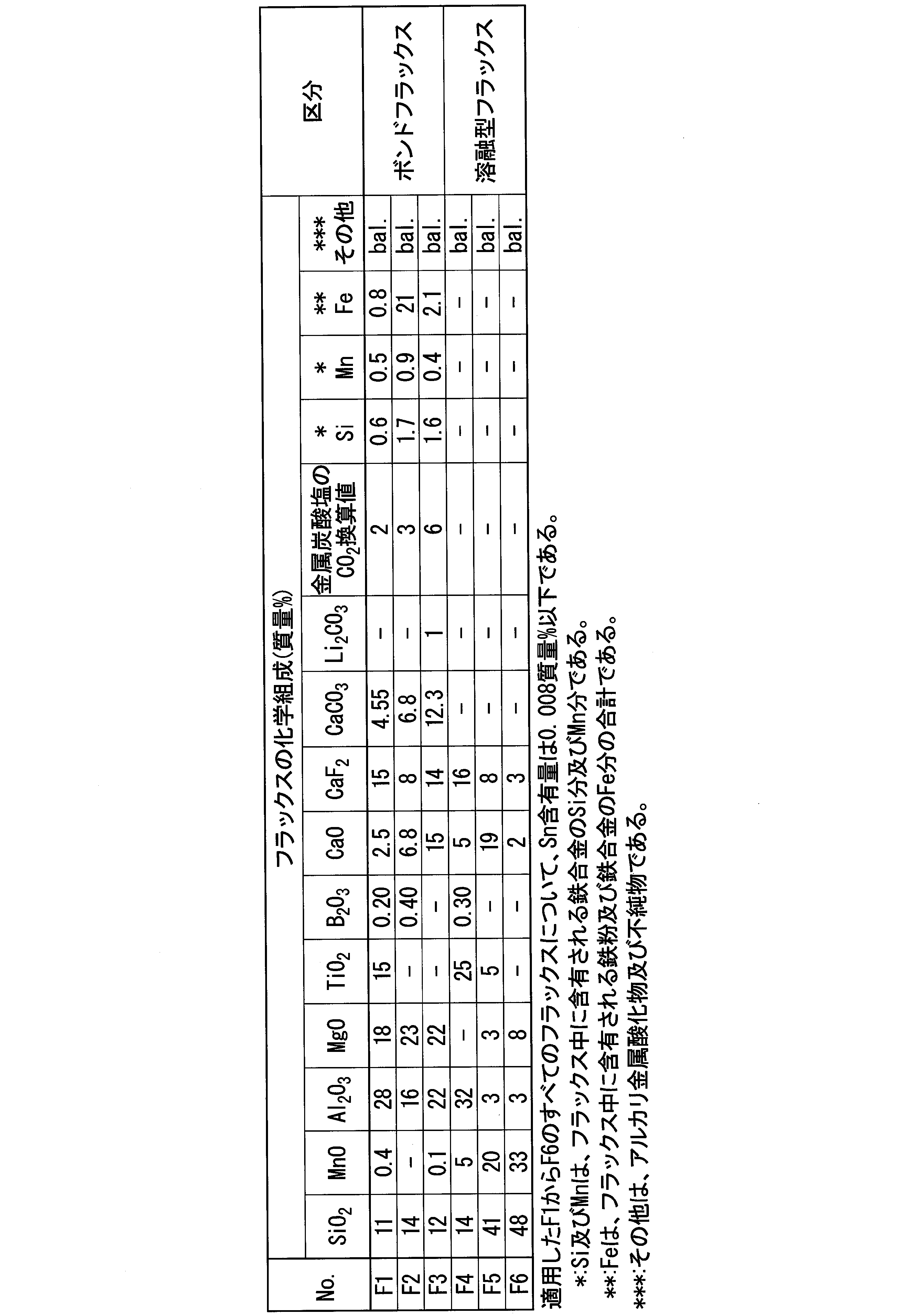
- Preferred slag components of the bond flux are, in mass%, SiO 2 : 5 to 20%, MnO: 0 to 1.0%, Al 2 O 3 : 15 to 30%, MgO: 10 to 25%, TiO 2 : 0 To 20%, B 2 O 3 : 0 to 1.0%, CaO: 2 to 20%, CaF 2 : 5 to 20%, total of CO 2 equivalents in metal carbonate: 1 to 8%,
- Si 0.1 to 2.0%
- Mn 0.1 to 1.0%
- Fe 0.5 to 35%
- the preferred slag component of the molten flux is, in mass%, SiO 2 : 10 to 50%, MnO: 5 to 35%, Al 2 O 3 : 3 to 35%, MgO: 0 to 10%, TiO 2 : 0 to 30%, B 2 O 3 : 0 to 1.0%, CaO: 2 to 25%, CaF 2 : 0 to 25%.
- 40 is used as the atomic weight of Ca
- 12 is used as the atomic weight of C
- 16 is used as the atomic weight of oxygen.
- Solid wires having various chemical compositions shown in Table 1 were trial-produced, combined with a bond flux or a molten flux shown in Table 2, and subjected to submerged arc welding to investigate the soundness, mechanical performance, and corrosion resistance of the weld metal.
- Solid wires shown in Table 1 were obtained by reducing the diameter of an original wire, annealing, and plating to obtain wires, and then drawing those wires to 4.0 mm. Further, for all the fluxes F1 to F6 in Table 2, the Sn content was 0.008% by mass or less.
- multi-layer welding was performed under the conditions of a welding current of 500 A, an arc voltage of 33 V, a welding speed of 30 cm / min, and a temperature between passes of 150 ⁇ 15 ° C.
- a welding current of 500 A an arc voltage of 33 V
- a welding speed of 30 cm / min a temperature between passes of 150 ⁇ 15 ° C.
- the base material in mass%, C: 0.15%, Si: 0.27%, Mn: 1.15%, P: 0.008%, S: 0.001%, Sn: 0.13% , Cu: 0.012%, Al: 0.03%, a steel plate of corrosion-resistant steel having a plate thickness of 20 mm and consisting of a balance of Fe and impurities.
- the soundness inside the weld metal was determined by an X-ray transmission test (JIS Z3104: 1995) and a side bending test (JIS Z3122: 2013). Thereafter, the weld metal was subjected to a tensile test and an impact test according to JIS Z3111: 2005 to evaluate the strength (tensile strength) and toughness of the weld metal. In addition, a corrosion resistance evaluation test was performed to evaluate local corrosion resistance in a corrosive environment.
- the side bending test was used to evaluate the presence or absence of welding defects (such as minute cracks in the weld metal).
- the side bending test was performed in accordance with the bending test method of JIS Z3122: 2013 butt welded joint.
- the type of the bending tester is a roller bending test including a receiving roller and a pressing jig.
- the type of bending test piece was a butt-welded side bending test piece (SBB), and one sample was taken from one welded joint test piece.
- the width of the test piece was equal to the plate thickness of the welded joint of 20 mm, and the thickness was 10 mm.
- the radius of curvature of the pushing jig was 2.0 times (20 mm) the thickness of the test piece.
- the test piece was set so that the pressing jig pressed near the center of the weld metal, and the span of the receiving roller was adjusted so that the bending angle was approximately 180 °.
- After the bending test mainly observe the center of the weld metal using a magnifying glass, measure the length of the opening cracks, and calculate the sum of the lengths of the individual opening cracks if multiple opening cracks have occurred. did.
- Table 4 shows the sum total of the lengths of the opening cracks at the center of the weld metal generated by the side bending test. When the weld metal was found to have no initial defects such as microcracks in the side bending test, it was described as 0 mm.
- the corrosion resistance was evaluated by preparing a corrosion test piece as follows. A sample (thickness 3 mm ⁇ width 60 mm ⁇ length 150 mm) for preparing a corrosion test piece shown in FIG. 1 was sampled from a sampling position 3 having a depth of 1 mm from the surface of the base material 1 so that the weld metal 2 was the center, After the shot blasting treatment, the specimen was heated and dried in a furnace having a furnace temperature of 80 ° C. to produce a test piece material. Thereafter, a paint (Neo Gosei Primer HB manufactured by Shinto Paint Co., Ltd.) was applied to both sides of the test piece material to prepare a test piece (painted test piece) having a film thickness of 200 to 350 ⁇ m.
- a paint Neo Gosei Primer HB manufactured by Shinto Paint Co., Ltd.
- a cross-cut 4 was applied to the painted test piece so as to straddle the weld metal, thereby producing a corrosion test piece 5 simulating a coating film flaw.
- the cross cut 4 was made by using a cutter knife to make a scratch from the top of the coating film to the surface of the underlying steel.
- SAEJ2334 test described in SAE (Society of Automatic Engineers) J2334 to evaluate corrosion resistance.
- the SAE J2334 test is an accelerated test performed under the conditions of dry-wet repetition in which three processes of wet, salt deposition, and dry are defined as one cycle (24 hours in total).
- the conditions of each process are as follows. Wet: 50 ° C., 100% RH, 6 hours, Salt adhesion: 0.5 mass% NaCl, 0.1 mass% CaCl 2 , 0.075 mass% NaHCO 3 aqueous solution immersion, 0.25 hours, Drying: 60 ° C., 50% RH, 17.75 hours.
- FIG. 3 shows an outline of one cycle.
- This corrosion test is a test that simulates a severe corrosion environment in which the amount of flying salt exceeds 1 mdd. This corrosion mode is said to be similar to the atmospheric exposure test.
- Test symbols Nos. T1 to T14, T30, and T31 in Tables 3 and 4 are examples of the present invention and test symbols Nos. T21 to T29 are comparative examples.
- Test symbol No. of the present invention example In T1 to T14, the weld metal and the chemical components of the wire symbols W1 to W14 in Table 1 satisfy the constituent requirements of the present invention, no welding defects (flaws) were recognized in the X-ray transmission test, and the welding was performed in the side bending test. The metal did not show any signs of micro-cracking and showed good bending ductility. Therefore, it was determined that a sound weld metal was obtained.
- the coating peeling / blowing area ratio is all less than 50%, and the coating flaw corrosion depth is all less than 0.50 mm, good mechanical properties. It was judged to have properties and corrosion resistance.
- the third type of flaws shown in Table 4 are cracks and similar flaws as described in JIS Z3104 Annex 4. Since the third type of flaws at T22, T23 and T28 were at the end of the weld bead, it was estimated to be so-called crater cracks.
- test symbol T21 the C content in the wire symbol W15 and the weld metal was small, the tensile strength of the weld metal was low, and the absorbed energy was low.
- test symbol T22 the C content in the wire symbol W16 and the weld metal was large, the tensile strength of the weld metal was high, and the absorbed energy was low. Crater cracks also occurred.
- test symbol T23 the Mn content in the wire symbol W17 and the weld metal was small, and the tensile strength of the weld metal was low. In addition, the Sn content was large, the absorbed energy of the weld metal was low, and crater cracks also occurred.
- the Mn content in the wire symbol W18 and the weld metal was large, the tensile strength of the weld metal was high, and the absorbed energy was low.
- the Sn content was small, the coating film peeling / blowing area ratio was 50% or more, and the coating film wound portion average corrosion depth was 0.50 mm or more, and the amount of corrosion was large.
- the wire symbol W19 and the Si content in the weld metal were small, and the absorbed energy of the weld metal was low.
- Test symbol T26 has a low Cu content in the wire symbol W20 and the weld metal, has a coating film peeling / blowing area ratio of 50% or more, and has a coating film flaw average corrosion depth of 0.50 mm or more and has a large amount of corrosion.
- the Mo content was large, the tensile strength was high, and the absorbed energy was low.
- test symbol T27 the wire symbol W21 and the Si content in the weld metal were large, the tensile strength of the weld metal was high, and the absorbed energy was low.
- Test symbol T28 has a small Sn content in the wire symbol W22 and the weld metal, has a coating film peeling / blowing area ratio of 50% or more, has a coating film average corrosion depth of 0.50 mm or more, and has a large amount of corrosion.
- the B content in the weld metal was large, the tensile strength of the weld metal was high, and crater cracks occurred.
- T29 and T37 the Cu content in the wire symbol 23 and the weld metal was large, and the absorbed energy of the weld metal was low. T29 also had a high Ti content in the weld metal and a high tensile strength.
- a weld metal having excellent weather resistance and paint peeling resistance even in an environment having a large amount of flying salt such as a beach area and a solid wire for submerged arc welding that is effective for forming the weld metal. It becomes possible. Further, if the weld metal and the solid wire for submerged arc welding of the present invention are applied to corrosion-resistant steel having excellent weather resistance and paint peeling resistance, both the base material and the welded part will have excellent weather resistance and paint peel resistance. This contributes to improving the weather resistance of the entire structure and extending the life of the coating.
Landscapes
- Chemical & Material Sciences (AREA)
- Engineering & Computer Science (AREA)
- Mechanical Engineering (AREA)
- Materials Engineering (AREA)
- Metallurgy (AREA)
- Organic Chemistry (AREA)
- Nonmetallic Welding Materials (AREA)
- Arc Welding In General (AREA)
Abstract
本願発明の溶接金属は、化学組成が、溶接金属全質量に対する質量%で、C:0.03-0.15%、Si:0.15-0.80%、Mn:1.2-2.0%、P:0.025%以下、S:0.020%以下、Al:0-0.050%、Cu:0.005-0.34%、Sn:0.05-0.40%、Mo:0-0.60%、Ni:0-0.50%、Cr:0-0.50%、Nb:0-0.300%、V:0-0.300%、Ti:0-0.040%、B:0-0.0070%、Ca:0-0.0050%、REM:0-0.0050%、Sb:0-0.0050%、N:0-0.0150%、O:0-0.1800%、残部:Fe及び不純物である。
Description
本発明は、溶接金属及びサブマージアーク溶接用ソリッドワイヤに関する。
長期間使用されている耐候性鋼材、すなわち大気腐食環境中に長期間暴露されている耐候性鋼材は、一般的に、鋼材の表面に保護性のあるさび層が形成される。耐候性鋼材では、このさび層が外界からの腐食性物質を遮蔽することで、それ以降の鋼材腐食が抑制されて耐候性を発揮する。そのため、耐候性鋼材は、塗装せずに裸のまま使用可能な鋼材として、橋梁等の構造物に用いられている。
しかしながら、海浜地域のような飛来塩分量が多い環境下では、耐候性鋼材の表面に保護性のあるさび層が形成されにくく、腐食を抑制する効果が発揮されにくい。また、内陸部であっても融雪剤が散布される地域では同様の問題が生じる。そのため、これらの地域では、裸のまま耐候性鋼材を用いることができず、塗装して用いる必要がある。
しかしながら、海浜地域のような飛来塩分量が多い環境下では、耐候性鋼材の表面に保護性のあるさび層が形成されにくく、腐食を抑制する効果が発揮されにくい。また、内陸部であっても融雪剤が散布される地域では同様の問題が生じる。そのため、これらの地域では、裸のまま耐候性鋼材を用いることができず、塗装して用いる必要がある。
さらに、前述の飛来塩分量が多い環境下では、塗膜(塗装膜)劣化によって塗膜傷が生じると、塗膜傷部直下の鋼材が直接的に腐食環境にさらされる。この場合、傷部を中心としてコブ状に塗膜が膨れ上がる形態の腐食が生じる。このような腐食の進行によってさらに塗膜傷部が累進的に拡大することで、構造物の腐食が進展し続ける。そのため、飛来塩分量が多い環境下では、構造物は、寿命延長を目的として、約10年毎に再塗装を実施されることが多い。しかしながら、再塗装は多大な工数がかかる。そのため、塗装寿命を延長し、補修塗装間隔を大きく延ばすことによって維持管理費用の低減を可能とする、新しい耐食鋼が開発されており、また、それに対応した溶接材料の開発がなされている。
例えば、特許文献1には、溶接材料のNiとCu及びMoの量と母材のNiとCu及びMoの量の比を規定することにより溶接部の選択腐食を防止する技術が開示されている。
特許文献2には、溶着金属のCu、Ni、Cr及びMo量を調整することによって、海浜耐候性に優れた溶接金属及び溶接材料を得る技術が開示されている。
特許文献3には、P含有の高耐候性鋼板を2電極で溶接することにより母材希釈を少なくし、高速溶接を行っても耐割れ性の良好なCu、Cr及びNiを適量含む溶接金属を形成することができるサブマージアーク溶接法を確立する技術が開示されている。
さらに、特許文献4には、W及びMoの少なくとも1種とSn及びSbの少なくとも1種とを含む耐食性に優れた溶接継手が開示されている。
特許文献2には、溶着金属のCu、Ni、Cr及びMo量を調整することによって、海浜耐候性に優れた溶接金属及び溶接材料を得る技術が開示されている。
特許文献3には、P含有の高耐候性鋼板を2電極で溶接することにより母材希釈を少なくし、高速溶接を行っても耐割れ性の良好なCu、Cr及びNiを適量含む溶接金属を形成することができるサブマージアーク溶接法を確立する技術が開示されている。
さらに、特許文献4には、W及びMoの少なくとも1種とSn及びSbの少なくとも1種とを含む耐食性に優れた溶接継手が開示されている。
しかしながら、特許文献1~4に記載の技術においても、特に溶接継手の最終層である余盛に施された塗膜は剥離しやすく、飛来塩分量が多い環境下では、この塗膜剥離部が腐食の起点となるという問題があった。これは、その周囲の平坦な母材に施された塗膜表面に比較して、余盛が凸状で複雑な表面形状を呈することで、塗装皮膜が薄くなる傾向があるためである。
特許文献1~4ではこのような問題点について考慮されていない。
特許文献1~4ではこのような問題点について考慮されていない。
本発明は、海浜地域など飛来塩分量が多い環境下においても耐候性及び耐塗装剥離性に優れた、溶接金属及びサブマージアーク溶接用ソリッドワイヤを提供することを目的とする。
上記課題を解決する本発明の要旨は以下の通りである。
(1)本発明の一態様に係る溶接金属は、化学組成が、溶接金属全質量に対する質量%で、C:0.03~0.15%、Si:0.15~0.80%、Mn:1.2~2.0%、P:0.025%以下、S:0.020%以下、Al:0~0.050%、Cu:0.005~0.34%、Sn:0.05~0.40%、Mo:0~0.60%、Ni:0~0.50%、Cr:0~0.50%、Nb:0~0.300%、V:0~0.300%、Ti:0~0.040%、B:0~0.0050%、Ca:0~0.0050%、REM:0~0.0050%、Sb:0~0.0070%、N:0~0.0150%、O:0~0.1800%、残部:Fe及び不純物である。
(1)本発明の一態様に係る溶接金属は、化学組成が、溶接金属全質量に対する質量%で、C:0.03~0.15%、Si:0.15~0.80%、Mn:1.2~2.0%、P:0.025%以下、S:0.020%以下、Al:0~0.050%、Cu:0.005~0.34%、Sn:0.05~0.40%、Mo:0~0.60%、Ni:0~0.50%、Cr:0~0.50%、Nb:0~0.300%、V:0~0.300%、Ti:0~0.040%、B:0~0.0050%、Ca:0~0.0050%、REM:0~0.0050%、Sb:0~0.0070%、N:0~0.0150%、O:0~0.1800%、残部:Fe及び不純物である。
(2)上記(1)に記載の溶接金属では、前記溶接金属全質量に対する質量%で、Cu:0.02~0.24%であってもよい。
(3)本発明の別の態様に係るサブマージアーク溶接用ソリッドワイヤは、化学組成が、前記ソリッドワイヤ全質量に対する質量%で、C:0.02~0.15%、Si:0.005~0.80%、Mn:1.5~3.5%、P:0.025%以下、S:0.020%以下、Al:0~0.050%、Cu:0.009~0.34%、Sn:0.05~0.40%、Mo:0~0.60%、Ni:0~0.50%、Cr:0~0.50%、Nb:0~0.300%、V:0~0.300%、Ti:0~0.250%、B:0~0.0120%、Ca:0~0.0050%、REM:0~0.0050%、Sb:0~0.0050%、N:0~0.0080%、O:0~0.0120%残部:Fe及び不純物である。
(4)上記(3)に記載のサブマージアーク溶接用ソリッドワイヤでは、前記ソリッドワイヤ全質量に対する質量%で、Cu:0.02~0.24%であってもよい。
本発明の上記態様に係る溶接金属及びサブマージアーク溶接用ソリッドワイヤによれば、海浜地域など飛来塩分量が多い環境下でも耐候性及び耐塗装剥離性に優れた溶接金属及び、その溶接金属を形成するのに有効なサブマージアーク溶接用ソリッドワイヤを提供することが可能となる。
本発明の上記態様に係る溶接金属では、特に、塗膜に傷が入るなどの塗膜劣化が生じた場合でも、劣化した塗膜下部の溶接金属の腐食速度が抑制される。そのため、腐食の進行に伴う塗膜膨れあるいは塗膜剥離の抑制に有効である。また、本発明の上記態様に係る溶接金属及びサブマージアーク溶接用ソリッドワイヤを用いて耐候性及び耐塗装剥離性に優れた耐食鋼を溶接すれば、母材部、溶接部ともに耐候性及び耐塗装剥離性に優れることとなるので、構造物全体の耐候性の向上ならびに塗装寿命の延長に寄与する。
本発明の上記態様に係る溶接金属では、特に、塗膜に傷が入るなどの塗膜劣化が生じた場合でも、劣化した塗膜下部の溶接金属の腐食速度が抑制される。そのため、腐食の進行に伴う塗膜膨れあるいは塗膜剥離の抑制に有効である。また、本発明の上記態様に係る溶接金属及びサブマージアーク溶接用ソリッドワイヤを用いて耐候性及び耐塗装剥離性に優れた耐食鋼を溶接すれば、母材部、溶接部ともに耐候性及び耐塗装剥離性に優れることとなるので、構造物全体の耐候性の向上ならびに塗装寿命の延長に寄与する。
本発明者らは、上記目的を達成できる溶接金属及びサブマージアーク溶接用ソリッドワイヤを得るためにそれぞれに必要な化学成分を見いだすべく、各種ボンドフラックス及び溶融型フラックスとソリッドワイヤとを組み合わせて溶接を実施し、種々の合金元素の作用効果について調査した。
その結果、スズ(Sn)及び銅(Cu)を溶接金属に適量含有させることによって飛来塩分の多い環境下における耐食性を向上できることを見いだした。
その結果、スズ(Sn)及び銅(Cu)を溶接金属に適量含有させることによって飛来塩分の多い環境下における耐食性を向上できることを見いだした。
具体的には、Snが溶接金属の耐食性を向上させる理由として、本発明者らは、溶接金属中の金属Snがスズイオン(II)(Sn2+)として溶出し、暴露されている部位、すなわち、酸性塩化物溶液中でインヒビター作用を示し、pHが低下したアノードでの腐食を抑制することを見いだした。さらに、Snが腐食促進作用を持つ鉄(III)イオン(Fe3+)の濃度を低減させて、飛来塩分の多い環境における耐食性を向上させる作用を有することを見いだした。
また、本発明者らは、Cuが溶接金属の耐食性を向上させる理由として、Cuを含有した溶接金属そのものの溶解反応(腐食反応)の反応速度を低減すること、及び、Cuを含有する溶接金属では、表面(余盛部など)に生成する腐食生成物(錆)が、特徴的な微細かつ緻密な構造を呈することにより、水、酸素、塩化物イオン等の透過を抑制する防食性の高い錆層を形成することを見いだした。さらに、CuはSnと共存することにより、Snの耐食性の向上効果を増強させる作用があることを見いだした。
また、溶接金属の機械的特性については、C、Si、Mnを適量含有し、Al、P、Sの成分を限定することによって良好になること、また、Mo、Ti及びB等の含有量をさらに調整することによりさらに良好になることを見いだした。
さらに、飛来塩分量が多い環境下でも耐候性及び耐塗装剥離性に優れた溶接金属を得るために好適なサブマージアーク溶接用ソリッドワイヤの成分も見いだした。
さらに、飛来塩分量が多い環境下でも耐候性及び耐塗装剥離性に優れた溶接金属を得るために好適なサブマージアーク溶接用ソリッドワイヤの成分も見いだした。
以下、本発明の一実施形態に係る溶接金属(本実施形態に係る溶接金属)および、本発明の別の実施形態に係るサブマージアーク溶接用ソリッドワイヤ(本実施形態に係るサブマージアーク溶接用ソリッドワイヤ)について説明する。
<溶接金属の成分>
まず、以下に本実施形態に係る溶接金属の成分の限定理由について説明する。成分の含有量についての%は、断りがない限り溶接金属全質量に対する質量%を示す。
サブマージアーク溶接用ソリッドワイヤは、サブマージアーク溶接によって溶接に供される鋼材の一部やフラックスとともに溶融し、凝固後、溶接金属となる。
まず、以下に本実施形態に係る溶接金属の成分の限定理由について説明する。成分の含有量についての%は、断りがない限り溶接金属全質量に対する質量%を示す。
サブマージアーク溶接用ソリッドワイヤは、サブマージアーク溶接によって溶接に供される鋼材の一部やフラックスとともに溶融し、凝固後、溶接金属となる。
[溶接金属中のC:0.03~0.15%]
溶接金属中のCは、溶接金属の強度と焼入れ性とを確保するために重要な元素である。C含有量が0.03%未満では、強度不足で靱性が低下する。そのため、溶接金属中のC含有量は0.03%以上とする。好ましい含有量は、0.04%以上である。
一方、溶接金属中のC含有量が0.15%を超えると、溶接金属の強度が高くなりすぎて靱性が低下する。また、高温割れが生じやすくなる。したがって、溶接金属中のC含有量は0.15%以下とする。好ましい含有量は、0.14%以下である。
溶接金属中のCは、溶接金属の強度と焼入れ性とを確保するために重要な元素である。C含有量が0.03%未満では、強度不足で靱性が低下する。そのため、溶接金属中のC含有量は0.03%以上とする。好ましい含有量は、0.04%以上である。
一方、溶接金属中のC含有量が0.15%を超えると、溶接金属の強度が高くなりすぎて靱性が低下する。また、高温割れが生じやすくなる。したがって、溶接金属中のC含有量は0.15%以下とする。好ましい含有量は、0.14%以下である。
[溶接金属中のSi:0.15~0.80%]
溶接金属中のSiは、溶接金属の靱性を高めるのに有効な成分である。Si含有量が0.15%未満では、靱性が低下する。そのため、溶接金属中のSi含有量は0.15%以上とする。好ましい含有量は、0.20%以上である。
一方、溶接金属中のSi含有量が0.80%を超えると、溶接金属の強度が高くなり靱性が低下する。そのため、溶接金属中のSi含有量は0.80%以下とする。好ましい含有量は、0.60%以下である。
溶接金属中のSiは、溶接金属の靱性を高めるのに有効な成分である。Si含有量が0.15%未満では、靱性が低下する。そのため、溶接金属中のSi含有量は0.15%以上とする。好ましい含有量は、0.20%以上である。
一方、溶接金属中のSi含有量が0.80%を超えると、溶接金属の強度が高くなり靱性が低下する。そのため、溶接金属中のSi含有量は0.80%以下とする。好ましい含有量は、0.60%以下である。
[溶接金属中のMn:1.2~2.0%]
溶接金属中のMnは、溶接金属の強度を高めるのに有効な成分である。Mn含有量が1.2%未満では、溶接金属の強度が低くなる。そのため、溶接金属中のMn含有量は1.2%以上とする。好ましい含有量は、1.3%以上である。
一方、溶接金属中のMn含有量が2.0%を超えると、溶接金属の強度が高くなり靱性が低下する。そのため、溶接金属中のMn含有量は2.0%以下とする。好ましい含有量は、1.8%以下である。
溶接金属中のMnは、溶接金属の強度を高めるのに有効な成分である。Mn含有量が1.2%未満では、溶接金属の強度が低くなる。そのため、溶接金属中のMn含有量は1.2%以上とする。好ましい含有量は、1.3%以上である。
一方、溶接金属中のMn含有量が2.0%を超えると、溶接金属の強度が高くなり靱性が低下する。そのため、溶接金属中のMn含有量は2.0%以下とする。好ましい含有量は、1.8%以下である。
[溶接金属中のCu:0.005~0.34%]
溶接金属中のCuは、溶接金属の耐食性を向上させる重要な元素である。Cu含有量が0.005%未満では、耐食性を向上させる効果が得られない。そのため、溶接金属中のCu含有量は0.005%以上とする。好ましい含有量は0.02%以上、より好ましい含有量は0.04%以上である。
一方、溶接金属中のCu含有量が0.34%を超えると、溶接金属の靱性が低下する。また、溶接金属中のCu含有量が多いと、溶接継手に対し曲げ加工を行った際に、溶接部に割れが生じる。そのため、溶接金属中のCu含有量は0.34%以下とする。好ましい含有量は、0.30%以下、より好ましい含有量は0.24%以下または0.20%以下である。
溶接金属中のCuは、溶接金属の耐食性を向上させる重要な元素である。Cu含有量が0.005%未満では、耐食性を向上させる効果が得られない。そのため、溶接金属中のCu含有量は0.005%以上とする。好ましい含有量は0.02%以上、より好ましい含有量は0.04%以上である。
一方、溶接金属中のCu含有量が0.34%を超えると、溶接金属の靱性が低下する。また、溶接金属中のCu含有量が多いと、溶接継手に対し曲げ加工を行った際に、溶接部に割れが生じる。そのため、溶接金属中のCu含有量は0.34%以下とする。好ましい含有量は、0.30%以下、より好ましい含有量は0.24%以下または0.20%以下である。
[溶接金属中のSn:0.05~0.40%]
溶接金属中のSnは、溶接金属の耐食性を向上させる重要な元素である。Sn含有量が0.05%未満では、耐食性向上の効果は得られない。そのため、溶接金属中のSn含有量は0.05%以上とする。好ましいSn含有量は0.10%以上である。
一方、溶接金属中のSn含有量が0.40%を超えると、高温割れが生じやすくなる。また、粒界へのSnの偏析により溶接金属の靱性が低下する。そのため、溶接金属中のSnは0.40%以下とする。好ましい含有量は、0.35%以下、0.30%以下または0.25%以下である。
溶接金属中のSnは、溶接金属の耐食性を向上させる重要な元素である。Sn含有量が0.05%未満では、耐食性向上の効果は得られない。そのため、溶接金属中のSn含有量は0.05%以上とする。好ましいSn含有量は0.10%以上である。
一方、溶接金属中のSn含有量が0.40%を超えると、高温割れが生じやすくなる。また、粒界へのSnの偏析により溶接金属の靱性が低下する。そのため、溶接金属中のSnは0.40%以下とする。好ましい含有量は、0.35%以下、0.30%以下または0.25%以下である。
[溶接金属中のAl:0~0.050%、P:0.025%以下、S:0.020%以下]
ワイヤ製造時に脱酸目的で添加されたAlは、溶接金属中に酸化物などの形態で一定量残存する場合が多い。
また、ワイヤなどのPおよびSも、溶接金属中に一定量残存する場合が多い。Al、PおよびSがワイヤ中に残存する場合、Al、P及びSは、溶接金属中にて共に低融点の化合物を生成して溶接金属の靱性を低下させるので、これらの含有量は出来るだけ低いことが望ましい。したがって、溶接金属中の、Al含有量は0~0.050%とし、P含有量は0.025%以下、S含有量は、0.020%以下とする。好ましくは、Al含有量は0~0.030%、P含有量は0.015%以下、S含有量は0.010%以下とする。Al含有量、P含有量およびS含有量の下限は0%である。
[溶接金属中のMo:0~0.60%]
溶接金属中のMoは、溶接金属の強度を高めるのに有効な成分である。本実施形態に係る溶接金属では、必要に応じてMoを含有させてもよい。強度向上効果を得る場合、Mo含有量を0.10%以上とすることが好ましい。
しかしながら、溶接金属中のMo含有量が0.60%を超えると、溶接金属中に金属間化合物が生成して溶接金属が著しく硬化し、靱性が低下する。よって、含有させる場合でもMo含有量を0.60%以下とする。好ましい含有量は、0.55%以下である。
溶接金属中のMoは、溶接金属の強度を高めるのに有効な成分である。本実施形態に係る溶接金属では、必要に応じてMoを含有させてもよい。強度向上効果を得る場合、Mo含有量を0.10%以上とすることが好ましい。
しかしながら、溶接金属中のMo含有量が0.60%を超えると、溶接金属中に金属間化合物が生成して溶接金属が著しく硬化し、靱性が低下する。よって、含有させる場合でもMo含有量を0.60%以下とする。好ましい含有量は、0.55%以下である。
[溶接金属中のNi:0~0.50%]
溶接金属中のNiは、溶接金属の耐食性を向上させるのに有効な成分である。本実施形態に係る溶接金属では、必要に応じてNiを含有させてもよい。耐食性向上効果を得る場合、溶接金属中のNi含有量を0.05%以上とすることが好ましい。
しかしながらSn共存下では、溶接金属中のNi含有量が0.50%を超えると、逆に耐塗装剥離性が低下する。そのため、含有させる場合でも溶接金属中のNi含有量を0.50%以下とする。好ましい含有量は、0.40%以下または0.25%以下である。
溶接金属中のNiは、溶接金属の耐食性を向上させるのに有効な成分である。本実施形態に係る溶接金属では、必要に応じてNiを含有させてもよい。耐食性向上効果を得る場合、溶接金属中のNi含有量を0.05%以上とすることが好ましい。
しかしながらSn共存下では、溶接金属中のNi含有量が0.50%を超えると、逆に耐塗装剥離性が低下する。そのため、含有させる場合でも溶接金属中のNi含有量を0.50%以下とする。好ましい含有量は、0.40%以下または0.25%以下である。
[溶接金属中のCr:0~0.50%]
溶接金属中のCrは、溶接金属の耐食性を向上させるのに有効な成分である。本実施形態に係る溶接金属では、必要に応じてCrを含有させてもよい。耐食性向上効果を得る場合、溶接金属中のCr含有量を0.05%以上とすることが好ましい。
しかしながらSn共存下では、溶接金属中のCr含有量が0.50%を超えると、逆に耐塗装剥離性が低下する。そのため、含有させる場合でも溶接金属中のCr含有量を0.50%以下とする。好ましい含有量は、0.40%以下または0.25%以下である。
溶接金属中のCrは、溶接金属の耐食性を向上させるのに有効な成分である。本実施形態に係る溶接金属では、必要に応じてCrを含有させてもよい。耐食性向上効果を得る場合、溶接金属中のCr含有量を0.05%以上とすることが好ましい。
しかしながらSn共存下では、溶接金属中のCr含有量が0.50%を超えると、逆に耐塗装剥離性が低下する。そのため、含有させる場合でも溶接金属中のCr含有量を0.50%以下とする。好ましい含有量は、0.40%以下または0.25%以下である。
[溶接金属中のNb:0~0.300%]
溶接金属中のNbは、溶接金属の強度を向上させるのに有効な成分である。本実施形態に係る溶接金属では、必要に応じてNbを含有させてもよい。強度向上効果を得る場合、溶接金属中のNb含有量を0.010%以上とすることが好ましい。
しかしながら、溶接金属中のNb含有量が0.300%を超えると、靱性低下を招く傾向がある。そのため、含有させる場合でも溶接金属中のNb含有量を0.200%以下とする。好ましい含有量は、0.100%以下または0.050%以下である。
溶接金属中のNbは、溶接金属の強度を向上させるのに有効な成分である。本実施形態に係る溶接金属では、必要に応じてNbを含有させてもよい。強度向上効果を得る場合、溶接金属中のNb含有量を0.010%以上とすることが好ましい。
しかしながら、溶接金属中のNb含有量が0.300%を超えると、靱性低下を招く傾向がある。そのため、含有させる場合でも溶接金属中のNb含有量を0.200%以下とする。好ましい含有量は、0.100%以下または0.050%以下である。
[溶接金属中のV:0~0.300%]
溶接金属中のVは、溶接金属の強度を向上させるのに有効な成分である。本実施形態に係る溶接金属では、必要に応じてVを含有させてもよい。強度向上効果を得る場合、溶接金属中のV含有量を0.010%以上とすることが好ましい。
しかしながら、溶接金属中のV含有量が0.300%を超えると、靱性低下を招く傾向がある。よって、含有させる場合でもV含有量を0.200%以下とする。好ましい含有量は、0.100%以下または0.050%以下である。
溶接金属中のVは、溶接金属の強度を向上させるのに有効な成分である。本実施形態に係る溶接金属では、必要に応じてVを含有させてもよい。強度向上効果を得る場合、溶接金属中のV含有量を0.010%以上とすることが好ましい。
しかしながら、溶接金属中のV含有量が0.300%を超えると、靱性低下を招く傾向がある。よって、含有させる場合でもV含有量を0.200%以下とする。好ましい含有量は、0.100%以下または0.050%以下である。
[溶接金属中のTi:0~0.040%]
[溶接金属中のB:0~0.0070%]
溶接金属中のTi及びBは、溶接金属の靱性を向上させるのに有効な元素である。そのため、必要に応じてTiとBとの1種または2種を含有させることができる。この効果を得る場合、Ti含有量を0.006%以上またはB含有量を0.0002%以上とすることが好ましい。
しかしながら、溶接金属中のTi含有量が0.040%を超えると、溶接金属の強度が高くなり過ぎることで、靱性が低下する。また、溶接金属中のB含有量が0.0070%を超えると、高温割れが生じやすくなる。したがって、これらの元素を含有させる場合でも、溶接金属中における、Ti含有量を0.040%以下、B含有量を0.0070%以下とする。B含有量は0.0050%以下であることが好ましい。溶接金属中のTiはフラックス中の金属Ti、Ti合金及びTi酸化物から添加され、Bはフラックス中のB合金及びB化合物から添加されることが多い。
[溶接金属中のCa:0~0.0050%]
溶接金属中にCaが不純物として混入する場合がある。Ca含有量が0.0050%を超えると、アーク安定性が損なわれるなど溶接作業性が低下する。そのため、溶接金属中のCa含有量は0.0050%以下とする。必要に応じて、Ca含有量を0.0030%以下、0.0010%以下又は0.0005%以下としてもよい。
溶接金属中にCaが不純物として混入する場合がある。Ca含有量が0.0050%を超えると、アーク安定性が損なわれるなど溶接作業性が低下する。そのため、溶接金属中のCa含有量は0.0050%以下とする。必要に応じて、Ca含有量を0.0030%以下、0.0010%以下又は0.0005%以下としてもよい。
[溶接金属中のREM:0~0.0050%]
溶接金属中にREMが不純物として混入する場合がある。REM含有量が0.0050%を超えると、アーク安定性が損なわれるなど溶接作業性が低下する。そのため、溶接金属中のREM含有量は0.0050%以下とする。必要に応じて、REM含有量を0.0030%以下、0.0010%以下又は0.0005%以下としてもよい。
溶接金属中にREMが不純物として混入する場合がある。REM含有量が0.0050%を超えると、アーク安定性が損なわれるなど溶接作業性が低下する。そのため、溶接金属中のREM含有量は0.0050%以下とする。必要に応じて、REM含有量を0.0030%以下、0.0010%以下又は0.0005%以下としてもよい。
[溶接金属中のSb:0~0.0050%]
溶接金属中にSbが不純物として混入する場合がある。Sb含有量が0.0050%を超えると、靱性が低下する。そのため、Sb含有量は0.0050%以下とする。必要に応じて、Sb含有量を0.0030%以下、0.0010%以下又は0.0005%以下としてもよい。
溶接金属中にSbが不純物として混入する場合がある。Sb含有量が0.0050%を超えると、靱性が低下する。そのため、Sb含有量は0.0050%以下とする。必要に応じて、Sb含有量を0.0030%以下、0.0010%以下又は0.0005%以下としてもよい。
[溶接金属中のN:0~0.0150%]
溶接金属中のNは靱性を低下させるので、N含有量は低い方が好ましい。しかしながら、Nを完全に除去するためには、多額の費用を要する。そのため、溶接金属の特性を損なわない範囲でNを含有してもよい。溶接金属中のN含有量が0.0150%を超えると靱性が特に低下するため、N含有量の上限を0.0150%とする。必要に応じて、N含有量を0.0100%以下、0.0080%以下、0.0050%以下としてもよい。必要に応じて、N含有量を0.0001%以上又は0.0010%以上としてもよい。
溶接金属中のNは靱性を低下させるので、N含有量は低い方が好ましい。しかしながら、Nを完全に除去するためには、多額の費用を要する。そのため、溶接金属の特性を損なわない範囲でNを含有してもよい。溶接金属中のN含有量が0.0150%を超えると靱性が特に低下するため、N含有量の上限を0.0150%とする。必要に応じて、N含有量を0.0100%以下、0.0080%以下、0.0050%以下としてもよい。必要に応じて、N含有量を0.0001%以上又は0.0010%以上としてもよい。
[溶接金属中のO:0~0.1800%]
溶接金属中のOは靱性を低下させるので、O含有量は低い方が好ましい。しかしながら、Oを完全に除去するためには、多額の費用を要する。そのため、溶接金属の特性を損なわない範囲でOを含有してもよい。O含有量が0.1800%を超えると靱性が特に低下するため、O含有量の上限を0.1800%とする。必要に応じて、O含有量を0.1000%以下、0.080%以下、0.0500%以下又は0.0400%としてもよい。必要に応じて、O含有量を0.0010%以上又は0.0100%以上としてもよい。
溶接金属中のOは靱性を低下させるので、O含有量は低い方が好ましい。しかしながら、Oを完全に除去するためには、多額の費用を要する。そのため、溶接金属の特性を損なわない範囲でOを含有してもよい。O含有量が0.1800%を超えると靱性が特に低下するため、O含有量の上限を0.1800%とする。必要に応じて、O含有量を0.1000%以下、0.080%以下、0.0500%以下又は0.0400%としてもよい。必要に応じて、O含有量を0.0010%以上又は0.0100%以上としてもよい。
上述したMo、Ni、Cr、Nb、V、Ti、B、Ca、REM、Sb、NおよびOは任意元素であり、含有させなくてもよいので、これらの含有量の下限は0%である。
[溶接金属の残部]
その他は、Fe及び不純物である。
その他は、Fe及び不純物である。
<サブマージアーク溶接用ソリッドワイヤの成分>
次に、上記耐食鋼の溶接金属の成分を得るために有効な、サブマージアーク溶接用ソリッドワイヤ(以下、単にワイヤという場合がある。)の成分の限定理由について説明する。以下成分の含有量についての%は、断りがない限り、ソリッドワイヤ全質量に対する質量%を示す。
次に、上記耐食鋼の溶接金属の成分を得るために有効な、サブマージアーク溶接用ソリッドワイヤ(以下、単にワイヤという場合がある。)の成分の限定理由について説明する。以下成分の含有量についての%は、断りがない限り、ソリッドワイヤ全質量に対する質量%を示す。
[ワイヤ中のC:0.02~0.15%]
ワイヤ中のCは、溶接後に溶接金属の強度を確保する重要な元素であると共に、アーク中の酸素と反応し、アーク雰囲気及び溶接金属の酸素量を低減する効果を有する元素である。ワイヤ中のC含有量が0.02%未満では、脱酸及び強度確保の効果が不十分であり、強度及び靱性ともに低下する。そのため、ワイヤ中のC含有量は0.02%以上とする。好ましい含有量は、0.03%以上である。
一方、ワイヤ中のC含有量が0.15%を超えると、溶接後に溶接金属の組織がマルテンサイト主体となり、溶接金属において、強度が高くなりすぎて靱性が低下する。また、高温割れが生じやすくなる。そのため、ワイヤ中のC含有量は0.15%以下とする。好ましい含有量は、0.14%以下である。
[ワイヤ中のSi:0.005~0.80%]
ワイヤ中のSiは、脱酸によって、溶接金属中の酸素量をコントロールする作用を有する元素である。Si含有量が0.005%未満では、脱酸効果が得られず、溶接金属の靱性が低下する。そのため、ワイヤ中のSi含有量は0.005%以上とする。好ましい含有量は、0.006%以上である。
一方、Si含有量が0.80%を超えると、溶接金属の強度が高くなりすぎて靱性が低下する。そのため、ワイヤ中のSi含有量は0.80%以下とする。好ましい含有量は0.60%以下または0.40%である。溶接金属の靱性を向上させるために、Si含有量を0.10%以下または0.05%以下としてもよい。
ワイヤ中のSiは、脱酸によって、溶接金属中の酸素量をコントロールする作用を有する元素である。Si含有量が0.005%未満では、脱酸効果が得られず、溶接金属の靱性が低下する。そのため、ワイヤ中のSi含有量は0.005%以上とする。好ましい含有量は、0.006%以上である。
一方、Si含有量が0.80%を超えると、溶接金属の強度が高くなりすぎて靱性が低下する。そのため、ワイヤ中のSi含有量は0.80%以下とする。好ましい含有量は0.60%以下または0.40%である。溶接金属の靱性を向上させるために、Si含有量を0.10%以下または0.05%以下としてもよい。
[ワイヤ中のMn:1.5~3.5%]
ワイヤ中のMnは、溶接金属の強度を高めるのに有効な成分である。Mn含有量が1.5%未満では、溶接金属の強度が十分に得られない。そのため、ワイヤ中のMn含有量は1.5%以上とする。
一方、ワイヤ中のMn含有量が3.5%を超えると、溶接金属の強度が高くなりすぎて靱性が低下する。したがって、ワイヤ中のMn含有量は3.5%以下とする。好ましい含有量は、3.0%以下である。
ワイヤ中のMnは、溶接金属の強度を高めるのに有効な成分である。Mn含有量が1.5%未満では、溶接金属の強度が十分に得られない。そのため、ワイヤ中のMn含有量は1.5%以上とする。
一方、ワイヤ中のMn含有量が3.5%を超えると、溶接金属の強度が高くなりすぎて靱性が低下する。したがって、ワイヤ中のMn含有量は3.5%以下とする。好ましい含有量は、3.0%以下である。
[ワイヤ中のCu:0.009~0.34%]
ワイヤ中のCuは、溶接金属の耐食性を向上させる重要な元素である。ワイヤ中のCu含有量が0.009%以下では、耐食性を向上させる効果が得られない。そのため、ワイヤ中のCu含有量は0.009%以上とする。好ましい含有量は、0.02%以上または0.03%以上である。より好ましくは、0.05%または0.07%以上である。
一方、ワイヤ中のCu含有量が0.34%を超えると、溶接金属の靱性が低下する。そのため、ワイヤ中のCu含有量は0.34%以下とする。好ましい含有量は、0.30%以下、より好ましい含有量は0.24%以下または0.20%以下である。
ワイヤが表面に銅めっきされている場合、銅めっきもワイヤの一部である。そのため、ワイヤ中のCu含有量には銅めっきに含まれるCuの量も含む。
[ワイヤ中のSn:0.05~0.40%]
ワイヤ中のSnは、溶接金属の耐食性を向上させる重要な元素である。ワイヤ中のSn含有量が0.05%未満では、耐食性向上の効果は得られない。そのため、ワイヤ中のSn含有量は0.05%以上とする。好ましい含有量は、0.10%以上である。
一方、ワイヤ中のSn含有量が0.40%を超えると、高温割れが生じやすくなる。また、粒界へのSnの偏析により溶接後に得られる溶接金属の靱性が低下する。したがって、ワイヤ中のSn含有量は0.40%以下とする。好ましい含有量は0.35%以下、0.30%以下または0.25%以下である。
溶接金属にSnを含有させようとする場合、Snを含有するワイヤを用いる方法とSnを含有するフラックスを用いる方法とがある。しかしながら、フラックスからの添加では濃度ばらつきによって含有量にむらが生じやすくなる。そのため、本実施形態では、Snを含有するワイヤを用いる。この場合、フラックスには、公知のフラックス(通常Sn≦0.001%)を用いることができる。
[ワイヤ中のAl:0~0.050%、P:0.025%以下、S:0.020%以下]
ワイヤ中のAl、P及びSは、共に低融点の化合物を生成して溶接金属の靱性を低下させるので、その含有量は出来るだけ低いことが望ましい。したがって、ワイヤ中の、Al含有量は0~0.050%、P含有量は0.025%以下、S含有量は0.020%以下とする。好ましくは、Al含有量は0~0.030%、P含有量は0.015%以下、S含有量は0.010%以下とする。Al含有量、P含有量、S含有量の下限は0%である。
ワイヤ中のAl、P及びSは、共に低融点の化合物を生成して溶接金属の靱性を低下させるので、その含有量は出来るだけ低いことが望ましい。したがって、ワイヤ中の、Al含有量は0~0.050%、P含有量は0.025%以下、S含有量は0.020%以下とする。好ましくは、Al含有量は0~0.030%、P含有量は0.015%以下、S含有量は0.010%以下とする。Al含有量、P含有量、S含有量の下限は0%である。
[ワイヤ中のMo:0~0.60%]
ワイヤ中のMoは、溶接金属の強度を確保する効果を有する。本実施形態に係るサブマージアーク溶接用ソリッドワイヤでは、必要に応じてMoを添加してもよい。強度向上効果を得る場合、ワイヤ中のMo含有量を、0.10%以上とすることが好ましい。
一方、ワイヤ中のMo含有量が0.60%を超えると、溶接金属中に金属間化合物が生成して溶接金属が著しく硬化し、靱性が低下する。したがって、ワイヤ中にMoを含有させる場合でも、ワイヤ中のMo含有量は0.60%以下とする。好ましい含有量は、0.55%以下である。
ワイヤ中のMoは、溶接金属の強度を確保する効果を有する。本実施形態に係るサブマージアーク溶接用ソリッドワイヤでは、必要に応じてMoを添加してもよい。強度向上効果を得る場合、ワイヤ中のMo含有量を、0.10%以上とすることが好ましい。
一方、ワイヤ中のMo含有量が0.60%を超えると、溶接金属中に金属間化合物が生成して溶接金属が著しく硬化し、靱性が低下する。したがって、ワイヤ中にMoを含有させる場合でも、ワイヤ中のMo含有量は0.60%以下とする。好ましい含有量は、0.55%以下である。
[ワイヤ中のNi:0~0.50%]
Niは、耐食性を向上させるのに有効な成分である。本実施形態に係るワイヤでは、必要に応じてNiを含有させてもよい。耐食性向上効果を得る場合、ワイヤ中のNi含有量を0.05%以上とすることが好ましい。
しかしながらSn共存下では、Ni含有量が0.50%を超えると、逆に耐塗装剥離性が低下する。よって、含有させる場合でも、ワイヤ中のNi含有量を0.50%以下とする。好ましい含有量は、0.40%以下または0.25%以下である。
Niは、耐食性を向上させるのに有効な成分である。本実施形態に係るワイヤでは、必要に応じてNiを含有させてもよい。耐食性向上効果を得る場合、ワイヤ中のNi含有量を0.05%以上とすることが好ましい。
しかしながらSn共存下では、Ni含有量が0.50%を超えると、逆に耐塗装剥離性が低下する。よって、含有させる場合でも、ワイヤ中のNi含有量を0.50%以下とする。好ましい含有量は、0.40%以下または0.25%以下である。
[ワイヤ中のCr:0~0.50%]
Crは、耐食性を向上させるのに有効な成分である。本実施形態に係るワイヤでは、必要に応じてCrを含有させてもよい。耐食性向上効果を得る場合、ワイヤ中のCr含有量を0.05%以上とすることが好ましい。
しかしながらSn共存下では、Cr含有量が0.50%を超えると、逆に耐塗装剥離性が低下する。よって、含有させる場合でも、ワイヤ中のCr含有量を0.50%以下とする。好ましい含有量は、0.40%以下または0.25%以下である。
Crは、耐食性を向上させるのに有効な成分である。本実施形態に係るワイヤでは、必要に応じてCrを含有させてもよい。耐食性向上効果を得る場合、ワイヤ中のCr含有量を0.05%以上とすることが好ましい。
しかしながらSn共存下では、Cr含有量が0.50%を超えると、逆に耐塗装剥離性が低下する。よって、含有させる場合でも、ワイヤ中のCr含有量を0.50%以下とする。好ましい含有量は、0.40%以下または0.25%以下である。
[ワイヤ中のNb:0~0.300%]
Nbは、強度を向上させるのに有効な成分である。本実施形態に係るワイヤでは、必要に応じてNbを含有させてもよい。強度向上効果を得る場合、ワイヤ中のNb含有量を0.010%以上とすることが好ましい。
しかしながら、Nb含有量が0.300%を超えると、靱性低下を招く傾向がある。そのため、含有させる場合でも、ワイヤ中のNb含有量を0.300%以下とする。好ましい含有量は、0.200%以下、0.100%以下または0.050%以下である。
Nbは、強度を向上させるのに有効な成分である。本実施形態に係るワイヤでは、必要に応じてNbを含有させてもよい。強度向上効果を得る場合、ワイヤ中のNb含有量を0.010%以上とすることが好ましい。
しかしながら、Nb含有量が0.300%を超えると、靱性低下を招く傾向がある。そのため、含有させる場合でも、ワイヤ中のNb含有量を0.300%以下とする。好ましい含有量は、0.200%以下、0.100%以下または0.050%以下である。
[ワイヤ中のV:0~0.300%]
Vは、強度を向上させるのに有効な成分である。本実施形態に係るワイヤでは、必要に応じてVを含有させてもよい。強度向上効果を得る場合、ワイヤ中のV含有量を0.010%以上とすることが好ましい。
しかしながら、ワイヤ中のV含有量が0.300%を超えると、靱性低下を招く傾向がある。そのため、含有させる場合でも、ワイヤ中のV含有量を0.300%以下とする。好ましい含有量は、0.200%以下、0.100%以下または0.050%以下である。
Vは、強度を向上させるのに有効な成分である。本実施形態に係るワイヤでは、必要に応じてVを含有させてもよい。強度向上効果を得る場合、ワイヤ中のV含有量を0.010%以上とすることが好ましい。
しかしながら、ワイヤ中のV含有量が0.300%を超えると、靱性低下を招く傾向がある。そのため、含有させる場合でも、ワイヤ中のV含有量を0.300%以下とする。好ましい含有量は、0.200%以下、0.100%以下または0.050%以下である。
[ワイヤ中のTi:0~0.250%]
Tiは、溶接金属の結晶粒微細化を促進し、溶接金属の靱性を向上させる効果がある。Tiを含有させることにより、介在物表層にTi酸化物が形成され、このTi酸化物が針状の微細なフェライト(アシキュラーフェライト)の生成核として作用し、結果として溶接金属組織は微細化すると考えられる。
Tiはまた、Nを固定し、固溶N量を減少させて靭性を向上させる効果も有する。したがって、Tiを含有させてもよい。とくに、適用鋼材のTi含有量が少ない場合、溶接ワイヤにTiを含有させることが望ましい。逆に、ワイヤ中のTi含有量が0.250%を超えると炭化物が生成し、溶接金属の靱性が低下する。そのため、ワイヤ中のTi含有量の上限を0.250%とした。必要に応じて、Ti含有量の上限を0.100%、0.060%、0.045%または0.030%としてもよい。
[ワイヤ中のB:0~0.0120%]
Bは、溶接金属の結晶粒粗大化を抑制する効果を有し、特に、溶接入熱量が比較的高水準の場合、溶接金属の靱性を顕著に向上させる効果を有する。溶接後の降温時、溶接金属がオーステナイト相からフェライト相に相変態する際、主にオーステナイト結晶粒界において、粗大な粒界フェライトが生じる傾向がある。B含有により、粒界におけるフェライトの生成が抑制されるので、結果として溶接金属組織が微細化し、溶接金属が高靭化する。この効果を得るため、ワイヤにBを含有させてもよい。逆に、ワイヤ中のB含有量が0.0120%を超えると溶接金属の焼入れ性が過剰となり、溶接金属の靱性が低下する。よってワイヤ中のB含有量の上限を0.0120%とする。必要に応じて、ワイヤ中のB含有量の上限を0.0080%、0.0050%、0.0025%、0.0010%、0.005%または0.002%としてもよい。
Bは、溶接金属の結晶粒粗大化を抑制する効果を有し、特に、溶接入熱量が比較的高水準の場合、溶接金属の靱性を顕著に向上させる効果を有する。溶接後の降温時、溶接金属がオーステナイト相からフェライト相に相変態する際、主にオーステナイト結晶粒界において、粗大な粒界フェライトが生じる傾向がある。B含有により、粒界におけるフェライトの生成が抑制されるので、結果として溶接金属組織が微細化し、溶接金属が高靭化する。この効果を得るため、ワイヤにBを含有させてもよい。逆に、ワイヤ中のB含有量が0.0120%を超えると溶接金属の焼入れ性が過剰となり、溶接金属の靱性が低下する。よってワイヤ中のB含有量の上限を0.0120%とする。必要に応じて、ワイヤ中のB含有量の上限を0.0080%、0.0050%、0.0025%、0.0010%、0.005%または0.002%としてもよい。
[ワイヤ中のCa:0~0.0050%]
ワイヤ中にCaが不純物として混入する場合がある。ワイヤ中のCa含有量が0.0050%を超えると、アーク安定性が損なわれるなど溶接作業性が低下する。そのため、ワイヤ中のCa含有量は0.0050%以下とする。必要に応じて、Ca含有量を0.0030%以下、0.0010%以下又は0.0005%以下としてもよい。
ワイヤ中にCaが不純物として混入する場合がある。ワイヤ中のCa含有量が0.0050%を超えると、アーク安定性が損なわれるなど溶接作業性が低下する。そのため、ワイヤ中のCa含有量は0.0050%以下とする。必要に応じて、Ca含有量を0.0030%以下、0.0010%以下又は0.0005%以下としてもよい。
[ワイヤ中のREM:0~0.0050%]
ワイヤ中にREMが不純物として混入する場合がある。ワイヤ中のREM含有量が0.0050%を超えると、アーク安定性が損なわれるなど溶接作業性が低下する。そのため、ワイヤ中のREM含有量は0.0050%以下とする。必要に応じて、ワイヤ中のREM含有量を0.0030%以下、0.0010%以下又は0.0005%以下としてもよい。
ワイヤ中にREMが不純物として混入する場合がある。ワイヤ中のREM含有量が0.0050%を超えると、アーク安定性が損なわれるなど溶接作業性が低下する。そのため、ワイヤ中のREM含有量は0.0050%以下とする。必要に応じて、ワイヤ中のREM含有量を0.0030%以下、0.0010%以下又は0.0005%以下としてもよい。
[ワイヤ中のSb:0~0.0050%]
ワイヤ中にSbが不純物として混入する場合がある。ワイヤ中のSb含有量が0.0050%を超えると、靱性が低下する。そのため、ワイヤ中のSb含有量は0.0050%以下とする。必要に応じて、ワイヤ中のSb含有量を0.0030%以下、0.0010%以下又は0.0005%以下としてもよい。
ワイヤ中にSbが不純物として混入する場合がある。ワイヤ中のSb含有量が0.0050%を超えると、靱性が低下する。そのため、ワイヤ中のSb含有量は0.0050%以下とする。必要に応じて、ワイヤ中のSb含有量を0.0030%以下、0.0010%以下又は0.0005%以下としてもよい。
[ワイヤ中のN:0~0.0080%]
溶接金属中のNは靱性を低下させるので、溶接後の溶接金属に含まれるN含有量を低減するため、ワイヤ中のN含有量は低い方が好ましい。しかしながら、Nを完全に除去するためには、多額の費用を要する。そのため、溶接金属の特性を損なわない範囲でNを含有してもよい。ワイヤ中のN含有量が0.0080%を超えると溶接金属の靱性が特に低下するので、ワイヤ中のN含有量の上限を0.0080%とする。必要に応じて、ワイヤ中のN含有量を0.0100%以下、0.0080%以下、0.0050%以下としてもよい。必要に応じて、ワイヤ中のN含有量を0.0001%以上又は0.0010%以上としてもよい。
溶接金属中のNは靱性を低下させるので、溶接後の溶接金属に含まれるN含有量を低減するため、ワイヤ中のN含有量は低い方が好ましい。しかしながら、Nを完全に除去するためには、多額の費用を要する。そのため、溶接金属の特性を損なわない範囲でNを含有してもよい。ワイヤ中のN含有量が0.0080%を超えると溶接金属の靱性が特に低下するので、ワイヤ中のN含有量の上限を0.0080%とする。必要に応じて、ワイヤ中のN含有量を0.0100%以下、0.0080%以下、0.0050%以下としてもよい。必要に応じて、ワイヤ中のN含有量を0.0001%以上又は0.0010%以上としてもよい。
[ワイヤ中のO:0~0.0120%]
溶接金属中のOは靱性を低下させるので、溶接金属に含まれるO含有量を低減するため、ワイヤ中のO含有量は低い方が好ましい。しかしながら、Oを完全に除去するためには、多額の費用を要する。そのため、溶接金属の特性を損なわない範囲でOを含有してもよい。ワイヤ中のO含有量が0.0120%を超えると溶接金属の靱性が特に低下するため、ワイヤ中のO含有量の上限を0.0120%とする。必要に応じて、ワイヤ中のO含有量を0.0100%以下、0.0080%以下、0.0050%以下としてもよい。必要に応じて、ワイヤ中のO含有量を0.0001%以上又は0.0010%以上としてもよい。
溶接金属中のOは靱性を低下させるので、溶接金属に含まれるO含有量を低減するため、ワイヤ中のO含有量は低い方が好ましい。しかしながら、Oを完全に除去するためには、多額の費用を要する。そのため、溶接金属の特性を損なわない範囲でOを含有してもよい。ワイヤ中のO含有量が0.0120%を超えると溶接金属の靱性が特に低下するため、ワイヤ中のO含有量の上限を0.0120%とする。必要に応じて、ワイヤ中のO含有量を0.0100%以下、0.0080%以下、0.0050%以下としてもよい。必要に応じて、ワイヤ中のO含有量を0.0001%以上又は0.0010%以上としてもよい。
上述したMo、Ni、Cr、Nb、V、Ti、B、Ca、REM、Sb、NおよびOは任意元素または不純物であり、含有させなくてもよいので、これらの含有量の下限は0%である。
[ワイヤの残部]
その他は、Fe及び不純物である。
その他は、Fe及び不純物である。
[ワイヤの製造方法]
上記サブマージアーク溶接用ソリッドワイヤは、通常の方法で製造できる。すなわち、成分を調整した鋼を溶解し、原線をつくり、縮径、焼鈍、めっきをして素線をつくり、素線を伸線して、所望の直径のワイヤとして製造することができる。
上記サブマージアーク溶接用ソリッドワイヤは、通常の方法で製造できる。すなわち、成分を調整した鋼を溶解し、原線をつくり、縮径、焼鈍、めっきをして素線をつくり、素線を伸線して、所望の直径のワイヤとして製造することができる。
[溶接金属の形成方法]
本実施形態に係る溶接金属は、例えば耐食鋼どうしをサブマージアーク溶接して得ることができる。サブマージアーク溶接では、溶接線上にあらかじめ顆粒状のフラックスを散布しておき、その中に本実施形態に係るサブマージアーク溶接用ソリッドワイヤを送り込み、フラックス中においてワイヤと母材との間のアークから生じるアーク熱で溶接する一般的なサブマージアーク溶接機器を適用できる。サブマージアーク溶接条件は、一般の方法であればよい。
<耐食鋼>
サブマージアーク溶接に供する耐食鋼の好ましい成分は、質量%で、C:0.06~0.20%、Si:0.005~1.50%、Mn:0.05~2.0%、P:0.028%以下、S:0.010%以下、Sn:0.02~0.45%、Cu:0.01~0.45%を含み、残部がFeおよび不純物を含む。Mo:0.35%以下をさらに含有していてもよい。
<フラックス>
本実施形態に係る溶接金属を形成するにあたっては、フラックスは、ボンドフラックス、溶融型フラックスのいずれも使用できる。これらのフラックスは、サブマージアーク溶接用の公知のフラックスでよい。例えば、日鐵住金溶接工業株式会社のYF-15、YF-15B、YF-800、NF-820などを使用できる。
好ましいボンドフラックスのスラグ成分は、質量%で、SiO2:5~20%、MnO:0~1.0%、Al2O3:15~30%、MgO:10~25%、TiO2:0~20%、B2O3:0~1.0%、CaO:2~20%、CaF2:5~20%、金属炭酸塩中のCO2換算値の合計:1~8%であり、合金成分として、Si:0.1~2.0%、Mn:0.1~1.0%、Fe:0.5~35%が含有されても良い。
また、好ましい溶融型フラックスのスラグ成分は、質量%で、SiO2:10~50%、MnO:5~35%、Al2O3:3~35%、MgO:0~10%、TiO2:0~30%、B2O3:0~1.0%、CaO:2~25%、CaF2:0~25%である。
ここで、金属炭酸塩中のCO2換算値とは、例えば、CaCO3が質量%で1%含有されていた場合、1%×(12+16×2)/(40+12+16×3)=0.44%と計算する。計算の際、Caの原子量として40、Cの原子量として12、酸素の原子量として16を用いる。
以下、実施例により本発明の効果をさらに詳細に説明する。
表1に示す各種化学組成を有するソリッドワイヤを試作し、表2に示すボンドフラックスまたは溶融型フラックスと組合せてサブマージアーク溶接し、溶接金属の健全性、機械的性能及び耐食性の調査を実施した。表1に示すソリッドワイヤは原線を縮径、焼鈍、めっきして素線とし、それらの素線を4.0mmまで伸線して用いた。また、表2のF1からF6のすべてのフラックスについて、Sn含有量は0.008質量%以下であった。
サブマージアーク溶接は、溶接電流500A、アーク電圧33V、溶接速度30cm/min、パス間温度150±15℃の条件にて多層溶接を実施した。母材には、質量%で、C:0.15%、Si:0.27%、Mn:1.15%、P:0.008%、S:0.001%、Sn:0.13%、Cu:0.012%、Al:0.03%、残部Feおよび不純物からなる板厚20mmの耐食鋼の鋼板を用いた。

上述したサブマージアーク溶接によって得られた溶接金属の化学組成を調べた。結果を表3に示す。

溶接終了後、溶接金属内部の健全性を、X線透過試験(JIS Z3104:1995)および側曲げ試験(JIS Z3122:2013)により判定した。
その後、JIS Z3111:2005に準じて溶着金属の引張試験および衝撃試験を行って溶接金属の強度(引張強さ)および靭性を評価した。
また、耐食性評価試験を行って腐食環境における耐局部腐食性を評価した。
その後、JIS Z3111:2005に準じて溶着金属の引張試験および衝撃試験を行って溶接金属の強度(引張強さ)および靭性を評価した。
また、耐食性評価試験を行って腐食環境における耐局部腐食性を評価した。
[X線透過試験]
X線透過試験により、溶接欠陥(割れおよびブローホール等)の有無を評価した。X線透過試験は、JIS Z3104-1995 鋼溶接継手の放射線透過試験方法に準拠して実施した。X線透過試験により判明した溶接欠陥の種類を表4に記載した。溶接長全長に対しX線透過試験を行い、溶接欠陥が認められない場合には、「きずなし」と記載した。きずがあった場合には、JIS Z3104の附属書4に示される第1種~第4種のいずれのきずであったかを示した。本発明では、「きずなし」の判定の場合を合格とした。
X線透過試験により、溶接欠陥(割れおよびブローホール等)の有無を評価した。X線透過試験は、JIS Z3104-1995 鋼溶接継手の放射線透過試験方法に準拠して実施した。X線透過試験により判明した溶接欠陥の種類を表4に記載した。溶接長全長に対しX線透過試験を行い、溶接欠陥が認められない場合には、「きずなし」と記載した。きずがあった場合には、JIS Z3104の附属書4に示される第1種~第4種のいずれのきずであったかを示した。本発明では、「きずなし」の判定の場合を合格とした。
[側曲げ試験]
側曲げ試験により、溶接欠陥(溶接金属の微小割れ等)の有無を評価した。なお、側曲げ試験は、JIS Z3122:2013 突合せ溶接継手の曲げ試験方法に準拠して実施した。曲げ試験機の種類は、受けローラと押しジグからなるローラ曲げ試験である。曲げ試験片の種類は、突合せ溶接の側曲げ試験片(SBB)とし、一つの溶接継手試験体より1本採取した。試験片の幅は、溶接継手の板厚20mmに等しくし、厚さは10mmとした。押しジグの曲率半径は、試験片板厚の2.0倍(20mm)とした。押しジグが溶接金属の中央付近を押すように試験片をセットし、曲げ角度は概略180°に近くなるように受けローラのスパンを調整した。曲げ試験後、主に溶接金属の中央を、拡大鏡を用いて観察し、開口き裂長さを測定し、開口き裂が複数生じていた場合には、個々の開口き裂長さの和として算出した。
側曲げ試験により生じる溶接金属中央位置の開口き裂長さの総和を表4に記載した。側曲げ試験により溶接金属に微小割れ等の初期欠陥がなかったものと認められる場合には、0mmと記載した。従来の曲げ試験関連諸規格の合否判定基準では、開口き裂長さの総和について「3mmを超えないこと」を定める例が多かったが、本発明では、1.0mm以下の場合のみを合格判定とした。
[溶接金属の引張強さおよび靭性]
溶接試験体の鋼板板厚の中心に相当する厚み位置から、溶接金属の衝撃試験片(JIS Z 2242:2005 Vノッチ試験片)及び引張試験片(JIS Z 2241:2011 10号試験片)を採取して、JIS Z3111:2005に準じて引張試験および衝撃試験を実施した。靱性の評価は0℃における衝撃試験により行い、各々繰返し数3本の平均としてシャルピー吸収エネルギーを求めた。
引張強さが490~750MPa、衝撃試験の吸収エネルギーが80J以上であれば良好と判断した。
溶接試験体の鋼板板厚の中心に相当する厚み位置から、溶接金属の衝撃試験片(JIS Z 2242:2005 Vノッチ試験片)及び引張試験片(JIS Z 2241:2011 10号試験片)を採取して、JIS Z3111:2005に準じて引張試験および衝撃試験を実施した。靱性の評価は0℃における衝撃試験により行い、各々繰返し数3本の平均としてシャルピー吸収エネルギーを求めた。
引張強さが490~750MPa、衝撃試験の吸収エネルギーが80J以上であれば良好と判断した。
[耐局部腐食性]
耐食性の評価は次のように腐食試験片を作製して行った。
図1に示す腐食試験片作製用の試料(厚さ3mm×幅60mm×長さ150mm)を溶接金属2が中心となるように母材1の表面から深さ1mmの採取位置3から採取し、ショットブラスト処理後、炉内温度が80℃である炉内で加熱乾燥させて試験片素材を作製した。
その後、この試験片素材の両面に、塗料(神東塗料(株)製ネオゴーセイプライマーHB)を塗装し膜厚が200~350μmの試験片(塗装試験片)を作製した。
耐食性の評価は次のように腐食試験片を作製して行った。
図1に示す腐食試験片作製用の試料(厚さ3mm×幅60mm×長さ150mm)を溶接金属2が中心となるように母材1の表面から深さ1mmの採取位置3から採取し、ショットブラスト処理後、炉内温度が80℃である炉内で加熱乾燥させて試験片素材を作製した。
その後、この試験片素材の両面に、塗料(神東塗料(株)製ネオゴーセイプライマーHB)を塗装し膜厚が200~350μmの試験片(塗装試験片)を作製した。
上記塗装試験片に対し、図2に示すように溶接金属を跨ぐようにクロスカット4を施すことで塗膜傷を模擬した腐食試験片5を作製した。クロスカット4は塗膜の上から下地の鋼表面まで達するスクラッチ傷を、カッターナイフを用いて施した。
その後、得られた腐食試験片5に対し、SAE(Society of Automotive Engineers) J2334に記載された試験(SAEJ2334試験)を行って耐食性を評価した。
その後、得られた腐食試験片5に対し、SAE(Society of Automotive Engineers) J2334に記載された試験(SAEJ2334試験)を行って耐食性を評価した。
ここで、SAE J2334試験とは、湿潤、塩分付着、乾燥の3過程を1サイクル(合計24時間)とした乾湿繰り返しの条件で行う加速試験である。各過程の条件は、以下の通りである。
湿潤:50℃、100%RH、6時間、
塩分付着:0.5質量%NaCl、0.1質量%CaCl2、0.075質量%NaHCO3水溶液浸漬、0.25時間、
乾燥:60℃、50%RH、17.75時間である。
1サイクルの概略を図3に示す。
この腐食試験は、飛来塩分量が1mddを超えるような厳しい腐食環境を模擬する試験である。この腐食形態が大気暴露試験に類似しているとされている。
湿潤:50℃、100%RH、6時間、
塩分付着:0.5質量%NaCl、0.1質量%CaCl2、0.075質量%NaHCO3水溶液浸漬、0.25時間、
乾燥:60℃、50%RH、17.75時間である。
1サイクルの概略を図3に示す。
この腐食試験は、飛来塩分量が1mddを超えるような厳しい腐食環境を模擬する試験である。この腐食形態が大気暴露試験に類似しているとされている。
以上のようなSAE J2334試験を80サイクル行った後に、各試験片の塗膜が剥離又は膨れた面積を計測し、塗膜剥離・膨れ面積率を算出した。その後、スクレーパーにて容易に剥離可能な表面の残存塗膜を除去した後、さらに生成したさび層をクエン酸アンモニウム溶液にて除去後、溶接金属の領域に限定して腐食深さを13点計測し、平均腐食深さとした。
塗膜剥離・膨れ面積率が50%未満、かつ、塗膜傷部平均腐食深さが0.50mm未満の場合を合格とした。表4にこれらの試験結果をまとめて示す。
塗膜剥離・膨れ面積率が50%未満、かつ、塗膜傷部平均腐食深さが0.50mm未満の場合を合格とした。表4にこれらの試験結果をまとめて示す。

表3及び表4中の試験記号No.T1~T14、T30、T31は本発明例、試験記号No.T21~T29は比較例である。本発明例の試験記号No.T1~T14は、溶接金属及び表1中のワイヤ記号W1~W14の化学成分が本発明の構成要件を満たし、X線透過試験で溶接欠陥(きず)が認められず、側曲げ試験においても溶接金属には微小な割れを生じている兆候は認められず、また、良好な曲げ延性を示していた。そのため、健全な溶接金属が得られていると判断した。
また、溶接金属の引張強さ及びシャルピー吸収エネルギーが良好で、塗装剥離・膨れ面積率は全て50%未満、かつ塗装傷部腐食深さは、全て0.50mm未満であれば、良好な機械的特性、耐食性を持つものと判断した。
表4に示す第3種のきずとは、JIS Z3104附属書4に記載されるように、割れ及びこれに類するきずである。T22、T23、T28の第3種のきずは、溶接ビードの終端にあったことから、いわゆるクレータ割れと推定した。
また、溶接金属の引張強さ及びシャルピー吸収エネルギーが良好で、塗装剥離・膨れ面積率は全て50%未満、かつ塗装傷部腐食深さは、全て0.50mm未満であれば、良好な機械的特性、耐食性を持つものと判断した。
表4に示す第3種のきずとは、JIS Z3104附属書4に記載されるように、割れ及びこれに類するきずである。T22、T23、T28の第3種のきずは、溶接ビードの終端にあったことから、いわゆるクレータ割れと推定した。
試験記号T10~T14は、溶接金属にMoが含有されているので、引張強さがやや高い傾向を示したが目標範囲内であった。
試験記号T21は、ワイヤ記号W15及び溶接金属中のC含有量が少なく、溶接金属の引張強さが低く、吸収エネルギーが低値であった。
試験記号T22は、ワイヤ記号W16及び溶接金属中のC含有量が多く、溶接金属の引張強さが高く、吸収エネルギーが低値であった。また、クレータ割れも生じた。
試験記号T23は、ワイヤ記号W17及び溶接金属中のMn含有量が少なく、溶接金属の引張強さが低値であった。また、Sn含有量が多く、溶接金属の吸収エネルギーが低く、さらにクレータ割れも生じた。
試験記号T22は、ワイヤ記号W16及び溶接金属中のC含有量が多く、溶接金属の引張強さが高く、吸収エネルギーが低値であった。また、クレータ割れも生じた。
試験記号T23は、ワイヤ記号W17及び溶接金属中のMn含有量が少なく、溶接金属の引張強さが低値であった。また、Sn含有量が多く、溶接金属の吸収エネルギーが低く、さらにクレータ割れも生じた。
試験記号T24は、ワイヤ記号W18及び溶接金属中のMn含有量が多く、溶接金属の引張強さが高く、吸収エネルギーが低値であった。また、Sn含有量が少なく、塗膜剥離・膨れ面積率が50%以上で、塗膜傷部平均腐食深さが0.50mm以上となり腐食量が多かった。
試験記号T25は、ワイヤ記号W19及び溶接金属中のSi含有量が少なく、溶接金属の吸収エネルギーが低値であった。
試験記号T26は、ワイヤ記号W20及び溶接金属中のCu含有量が少なく、塗膜剥離・膨れ面積率が50%以上で、塗膜傷部平均腐食深さが0.50mm以上となり腐食量が多かった。また、Mo含有量が多く、引張強さが高く、吸収エネルギーが低値であった。
試験記号T25は、ワイヤ記号W19及び溶接金属中のSi含有量が少なく、溶接金属の吸収エネルギーが低値であった。
試験記号T26は、ワイヤ記号W20及び溶接金属中のCu含有量が少なく、塗膜剥離・膨れ面積率が50%以上で、塗膜傷部平均腐食深さが0.50mm以上となり腐食量が多かった。また、Mo含有量が多く、引張強さが高く、吸収エネルギーが低値であった。
試験記号T27は、ワイヤ記号W21及び溶接金属中のSi含有量が多く、溶接金属の引張強さが高く、吸収エネルギーが低値であった。
試験記号T28は、ワイヤ記号W22及び溶接金属中のSn含有量が少なく、塗膜剥離・膨れ面積率が50%以上で、塗膜傷部平均腐食深さが0.50mm以上となり腐食量が多かった。また、溶接金属中のB含有量が多く、溶接金属の引張強さが高く、クレータ割れが生じた。
試験記号T29、T37は、ワイヤ記号23及び溶接金属中のCu含有量が多く、溶接金属の吸収エネルギーが低値であった。また、T29は溶接金属中のTi含有量も多く、引張強さが高かった。
試験記号T28は、ワイヤ記号W22及び溶接金属中のSn含有量が少なく、塗膜剥離・膨れ面積率が50%以上で、塗膜傷部平均腐食深さが0.50mm以上となり腐食量が多かった。また、溶接金属中のB含有量が多く、溶接金属の引張強さが高く、クレータ割れが生じた。
試験記号T29、T37は、ワイヤ記号23及び溶接金属中のCu含有量が多く、溶接金属の吸収エネルギーが低値であった。また、T29は溶接金属中のTi含有量も多く、引張強さが高かった。
本発明によれば、海浜地域など飛来塩分量が多い環境下でも耐候性及び耐塗装剥離性に優れた溶接金属及び、その溶接金属を形成するのに有効なサブマージアーク溶接用ソリッドワイヤを提供することが可能となる。また、本発明の溶接金属及びサブマージアーク溶接用ソリッドワイヤを、耐候性及び耐塗装剥離性に優れた耐食鋼に適用すれば、母材部、溶接部ともに耐候性及び耐塗装剥離性に優れることとなるため、構造物全体の耐候性の向上ならびに塗装寿命の延長に寄与する。
1 母材
2 溶接金属
3 腐食試験片作製用試料の採取位置
4 クロスカット
5 腐食試験片
2 溶接金属
3 腐食試験片作製用試料の採取位置
4 クロスカット
5 腐食試験片
Claims (4)
- 化学組成が、溶接金属全質量に対する質量%で、
C:0.03~0.15%、
Si:0.15~0.80%、
Mn:1.2~2.0%、
P:0.025%以下、
S:0.020%以下、
Al:0~0.050%、
Cu:0.005~0.34%、
Sn:0.05~0.40%、
Mo:0~0.60%、
Ni:0~0.50%、
Cr:0~0.50%、
Nb:0~0.300%、
V:0~0.300%、
Ti:0~0.040%、
B:0~0.0070%、
Ca:0~0.0050%、
REM:0~0.0050%、
Sb:0~0.0050%、
N:0~0.0150%、
O:0~0.1800%、
残部:Fe及び不純物である
ことを特徴とする溶接金属。 - 前記溶接金属全質量に対する質量%で、Cu:0.02~0.24%であることを特徴とする請求項1に記載の溶接金属。
- サブマージアーク溶接用ソリッドワイヤであって、
化学組成が、前記ソリッドワイヤ全質量に対する質量%で、
C:0.02~0.15%、
Si:0.005~0.80%、
Mn:1.5~3.5%、
P:0.025%以下、
S:0.020%以下、
Al:0~0.050%、
Cu:0.009~0.34%、
Sn:0.05~0.40%、
Mo:0~0.60%、
Ni:0~0.50%、
Cr:0~0.50%、
Nb:0~0.300%、
V:0~0.300%、
Ti:0~0.250%、
B:0~0.0120%、
Ca:0~0.0050%、
REM:0~0.0050%、
Sb:0~0.0050%、
N:0~0.0080%、
O:0~0.0120%、
残部:Fe及び不純物である
ことを特徴とするサブマージアーク溶接用ソリッドワイヤ。 - 前記ソリッドワイヤ全質量に対する質量%で、Cu:0.02~0.24%であることを特徴とする請求項3に記載のサブマージアーク溶接用ソリッドワイヤ。
Priority Applications (2)
| Application Number | Priority Date | Filing Date | Title |
|---|---|---|---|
| JP2020516918A JP6984743B2 (ja) | 2018-08-01 | 2018-08-01 | 溶接金属及びサブマージアーク溶接用ソリッドワイヤ |
| PCT/JP2018/028906 WO2020026385A1 (ja) | 2018-08-01 | 2018-08-01 | 溶接金属及びサブマージアーク溶接用ソリッドワイヤ |
Applications Claiming Priority (1)
| Application Number | Priority Date | Filing Date | Title |
|---|---|---|---|
| PCT/JP2018/028906 WO2020026385A1 (ja) | 2018-08-01 | 2018-08-01 | 溶接金属及びサブマージアーク溶接用ソリッドワイヤ |
Publications (1)
| Publication Number | Publication Date |
|---|---|
| WO2020026385A1 true WO2020026385A1 (ja) | 2020-02-06 |
Family
ID=69230601
Family Applications (1)
| Application Number | Title | Priority Date | Filing Date |
|---|---|---|---|
| PCT/JP2018/028906 WO2020026385A1 (ja) | 2018-08-01 | 2018-08-01 | 溶接金属及びサブマージアーク溶接用ソリッドワイヤ |
Country Status (2)
| Country | Link |
|---|---|
| JP (1) | JP6984743B2 (ja) |
| WO (1) | WO2020026385A1 (ja) |
Cited By (1)
| Publication number | Priority date | Publication date | Assignee | Title |
|---|---|---|---|---|
| CN111975245A (zh) * | 2020-09-02 | 2020-11-24 | 燕山大学 | 免涂装耐候钢桥用抗拉强度650MPa级埋弧自动焊焊丝及盘条 |
Citations (3)
| Publication number | Priority date | Publication date | Assignee | Title |
|---|---|---|---|---|
| WO2014181534A1 (ja) * | 2013-05-09 | 2014-11-13 | Jfeスチール株式会社 | 耐候性に優れた鋼材 |
| JP2018047487A (ja) * | 2016-09-21 | 2018-03-29 | 新日鐵住金株式会社 | 耐食鋼のガスシールドアーク溶接用フラックス入りワイヤ |
| JP2018118283A (ja) * | 2017-01-26 | 2018-08-02 | 新日鐵住金株式会社 | 耐食鋼の溶接金属及びサブマージアーク溶接用ソリッドワイヤ |
Family Cites Families (1)
| Publication number | Priority date | Publication date | Assignee | Title |
|---|---|---|---|---|
| JP2010064110A (ja) * | 2008-09-11 | 2010-03-25 | Sumitomo Metal Ind Ltd | 石炭・鉱石運搬船ホールド用溶接継手 |
-
2018
- 2018-08-01 JP JP2020516918A patent/JP6984743B2/ja active Active
- 2018-08-01 WO PCT/JP2018/028906 patent/WO2020026385A1/ja active Application Filing
Patent Citations (3)
| Publication number | Priority date | Publication date | Assignee | Title |
|---|---|---|---|---|
| WO2014181534A1 (ja) * | 2013-05-09 | 2014-11-13 | Jfeスチール株式会社 | 耐候性に優れた鋼材 |
| JP2018047487A (ja) * | 2016-09-21 | 2018-03-29 | 新日鐵住金株式会社 | 耐食鋼のガスシールドアーク溶接用フラックス入りワイヤ |
| JP2018118283A (ja) * | 2017-01-26 | 2018-08-02 | 新日鐵住金株式会社 | 耐食鋼の溶接金属及びサブマージアーク溶接用ソリッドワイヤ |
Cited By (2)
| Publication number | Priority date | Publication date | Assignee | Title |
|---|---|---|---|---|
| CN111975245A (zh) * | 2020-09-02 | 2020-11-24 | 燕山大学 | 免涂装耐候钢桥用抗拉强度650MPa级埋弧自动焊焊丝及盘条 |
| CN111975245B (zh) * | 2020-09-02 | 2021-07-27 | 燕山大学 | 免涂装耐候钢桥用抗拉强度650MPa级埋弧自动焊焊丝及盘条 |
Also Published As
| Publication number | Publication date |
|---|---|
| JPWO2020026385A1 (ja) | 2020-08-20 |
| JP6984743B2 (ja) | 2021-12-22 |
Similar Documents
| Publication | Publication Date | Title |
|---|---|---|
| JP4811277B2 (ja) | 石炭・鉱石運搬船ホールド用耐食性鋼材 | |
| TWI447261B (zh) | 熔融Al-Zn系鍍敷鋼板 | |
| JP4445444B2 (ja) | 複合耐食性に優れた船舶用鋼材および溶接構造物 | |
| JP2010275634A (ja) | Zn−Mg系めっき鋼板およびその製造方法 | |
| JP2017115205A (ja) | めっき密着性に優れた溶融Zn−Al−Mg合金めっき鋼板の製造方法 | |
| JP4980294B2 (ja) | 亜鉛めっき鋼板用被覆アーク溶接棒 | |
| KR102272173B1 (ko) | 플럭스 내포 와이어의 제조 방법, 플럭스 내포 와이어 및 용접 이음의 제조 방법 | |
| WO2020026385A1 (ja) | 溶接金属及びサブマージアーク溶接用ソリッドワイヤ | |
| JP6848479B2 (ja) | 耐食鋼の溶接金属及びサブマージアーク溶接用ソリッドワイヤ | |
| JP2002336989A (ja) | 海浜耐候性鋼用溶接材料 | |
| JP6658424B2 (ja) | 耐食鋼のガスシールドアーク溶接用フラックス入りワイヤ | |
| JP2019107673A (ja) | 耐食鋼のガスシールドアーク溶接用フラックス入りワイヤ、及び溶接継手の製造方法 | |
| JP2018047486A (ja) | 耐食鋼の水平すみ肉ガスシールドアーク溶接用フラックス入りワイヤ | |
| JP7277742B2 (ja) | ソリッドワイヤ | |
| JP5862166B2 (ja) | 船舶艤装用耐食鋼材 | |
| JPH09206984A (ja) | 薄板用ガスシールドアーク溶接方法 | |
| EP3753670B1 (en) | Method for manufacturing flux-cored wire, flux-cored wire and method for manufacturing welded joint | |
| JP3466076B2 (ja) | 耐食性と溶接性に優れた鋼材 | |
| JP3971853B2 (ja) | 耐食性に優れた鋼材 | |
| JP6787171B2 (ja) | 耐食鋼のガスシールドアーク溶接用ソリッドワイヤ | |
| JP2020189302A (ja) | 原油油槽鋼の低水素系被覆アーク溶接棒 | |
| JP2000313939A (ja) | 耐候性に優れた溶接鋼管の製造法 | |
| JP2007105734A (ja) | 耐Cu脆化割れ性に優れたオーステナイト系ステンレス鋼被覆アーク溶接棒 | |
| JPH09165647A (ja) | 耐候性に優れた溶接構造用鋼 | |
| JP2001262273A (ja) | 溶接性に優れた耐候性鋼管 |
Legal Events
| Date | Code | Title | Description |
|---|---|---|---|
| 121 | Ep: the epo has been informed by wipo that ep was designated in this application |
Ref document number: 18928289 Country of ref document: EP Kind code of ref document: A1 |
|
| ENP | Entry into the national phase |
Ref document number: 2020516918 Country of ref document: JP Kind code of ref document: A |
|
| NENP | Non-entry into the national phase |
Ref country code: DE |
|
| 122 | Ep: pct application non-entry in european phase |
Ref document number: 18928289 Country of ref document: EP Kind code of ref document: A1 |