WO2020021792A1 - 物品搬送装置 - Google Patents
物品搬送装置 Download PDFInfo
- Publication number
- WO2020021792A1 WO2020021792A1 PCT/JP2019/016109 JP2019016109W WO2020021792A1 WO 2020021792 A1 WO2020021792 A1 WO 2020021792A1 JP 2019016109 W JP2019016109 W JP 2019016109W WO 2020021792 A1 WO2020021792 A1 WO 2020021792A1
- Authority
- WO
- WIPO (PCT)
- Prior art keywords
- stator
- mover
- traveling
- opening
- path
- Prior art date
- Legal status (The legal status is an assumption and is not a legal conclusion. Google has not performed a legal analysis and makes no representation as to the accuracy of the status listed.)
- Ceased
Links
Images



Classifications
-
- B—PERFORMING OPERATIONS; TRANSPORTING
- B65—CONVEYING; PACKING; STORING; HANDLING THIN OR FILAMENTARY MATERIAL
- B65G—TRANSPORT OR STORAGE DEVICES, e.g. CONVEYORS FOR LOADING OR TIPPING, SHOP CONVEYOR SYSTEMS OR PNEUMATIC TUBE CONVEYORS
- B65G54/00—Non-mechanical conveyors not otherwise provided for
- B65G54/02—Non-mechanical conveyors not otherwise provided for electrostatic, electric, or magnetic
-
- B—PERFORMING OPERATIONS; TRANSPORTING
- B65—CONVEYING; PACKING; STORING; HANDLING THIN OR FILAMENTARY MATERIAL
- B65G—TRANSPORT OR STORAGE DEVICES, e.g. CONVEYORS FOR LOADING OR TIPPING, SHOP CONVEYOR SYSTEMS OR PNEUMATIC TUBE CONVEYORS
- B65G23/00—Driving gear for endless conveyors; Belt- or chain-tensioning arrangements
- B65G23/22—Arrangements or mountings of driving motors
- B65G23/23—Arrangements or mountings of driving motors of electric linear motors
-
- B—PERFORMING OPERATIONS; TRANSPORTING
- B65—CONVEYING; PACKING; STORING; HANDLING THIN OR FILAMENTARY MATERIAL
- B65G—TRANSPORT OR STORAGE DEVICES, e.g. CONVEYORS FOR LOADING OR TIPPING, SHOP CONVEYOR SYSTEMS OR PNEUMATIC TUBE CONVEYORS
- B65G23/00—Driving gear for endless conveyors; Belt- or chain-tensioning arrangements
- B65G23/24—Gearing between driving motor and belt- or chain-engaging elements
-
- B—PERFORMING OPERATIONS; TRANSPORTING
- B65—CONVEYING; PACKING; STORING; HANDLING THIN OR FILAMENTARY MATERIAL
- B65G—TRANSPORT OR STORAGE DEVICES, e.g. CONVEYORS FOR LOADING OR TIPPING, SHOP CONVEYOR SYSTEMS OR PNEUMATIC TUBE CONVEYORS
- B65G41/00—Supporting frames or bases for conveyors as a whole, e.g. transportable conveyor frames
- B65G41/007—Means for moving conveyor frames and control arrangements therefor
- B65G41/008—Means for moving conveyor frames and control arrangements therefor frames mounted on wheels or caterpillar
-
- B—PERFORMING OPERATIONS; TRANSPORTING
- B65—CONVEYING; PACKING; STORING; HANDLING THIN OR FILAMENTARY MATERIAL
- B65G—TRANSPORT OR STORAGE DEVICES, e.g. CONVEYORS FOR LOADING OR TIPPING, SHOP CONVEYOR SYSTEMS OR PNEUMATIC TUBE CONVEYORS
- B65G47/00—Article or material-handling devices associated with conveyors; Methods employing such devices
- B65G47/34—Devices for discharging articles or materials from conveyor
- B65G47/38—Devices for discharging articles or materials from conveyor by dumping, tripping, or releasing load carriers
-
- B—PERFORMING OPERATIONS; TRANSPORTING
- B65—CONVEYING; PACKING; STORING; HANDLING THIN OR FILAMENTARY MATERIAL
- B65G—TRANSPORT OR STORAGE DEVICES, e.g. CONVEYORS FOR LOADING OR TIPPING, SHOP CONVEYOR SYSTEMS OR PNEUMATIC TUBE CONVEYORS
- B65G47/00—Article or material-handling devices associated with conveyors; Methods employing such devices
- B65G47/34—Devices for discharging articles or materials from conveyor
- B65G47/46—Devices for discharging articles or materials from conveyor and distributing, e.g. automatically, to desired points
-
- B—PERFORMING OPERATIONS; TRANSPORTING
- B65—CONVEYING; PACKING; STORING; HANDLING THIN OR FILAMENTARY MATERIAL
- B65G—TRANSPORT OR STORAGE DEVICES, e.g. CONVEYORS FOR LOADING OR TIPPING, SHOP CONVEYOR SYSTEMS OR PNEUMATIC TUBE CONVEYORS
- B65G47/00—Article or material-handling devices associated with conveyors; Methods employing such devices
- B65G47/52—Devices for transferring articles or materials between conveyors i.e. discharging or feeding devices
- B65G47/64—Switching conveyors
- B65G47/641—Switching conveyors by a linear displacement of the switching conveyor
- B65G47/642—Switching conveyors by a linear displacement of the switching conveyor in a horizontal plane
-
- B—PERFORMING OPERATIONS; TRANSPORTING
- B65—CONVEYING; PACKING; STORING; HANDLING THIN OR FILAMENTARY MATERIAL
- B65G—TRANSPORT OR STORAGE DEVICES, e.g. CONVEYORS FOR LOADING OR TIPPING, SHOP CONVEYOR SYSTEMS OR PNEUMATIC TUBE CONVEYORS
- B65G47/00—Article or material-handling devices associated with conveyors; Methods employing such devices
- B65G47/74—Feeding, transfer, or discharging devices of particular kinds or types
- B65G47/94—Devices for flexing or tilting travelling structures; Throw-off carriages
- B65G47/96—Devices for tilting links or platform
-
- B—PERFORMING OPERATIONS; TRANSPORTING
- B65—CONVEYING; PACKING; STORING; HANDLING THIN OR FILAMENTARY MATERIAL
- B65G—TRANSPORT OR STORAGE DEVICES, e.g. CONVEYORS FOR LOADING OR TIPPING, SHOP CONVEYOR SYSTEMS OR PNEUMATIC TUBE CONVEYORS
- B65G2207/00—Indexing codes relating to constructional details, configuration and additional features of a handling device, e.g. Conveyors
- B65G2207/18—Crossing conveyors
-
- B—PERFORMING OPERATIONS; TRANSPORTING
- B65—CONVEYING; PACKING; STORING; HANDLING THIN OR FILAMENTARY MATERIAL
- B65G—TRANSPORT OR STORAGE DEVICES, e.g. CONVEYORS FOR LOADING OR TIPPING, SHOP CONVEYOR SYSTEMS OR PNEUMATIC TUBE CONVEYORS
- B65G2812/00—Indexing codes relating to the kind or type of conveyors
- B65G2812/02—Belt or chain conveyors
- B65G2812/02128—Belt conveyors
- B65G2812/02138—Common features for belt conveyors
- B65G2812/02148—Driving means for the belts
Definitions
- the present invention relates to an article transport apparatus that transports articles using a ground primary linear motor.
- an object of the present invention is to provide an article transport device that can suppress the entry of foreign matter into a motor.
- an article transporting device includes a bogie that travels along a predetermined traveling path, and a ground-side facility having a pair of traveling rails that defines the traveling path.
- the trolley is a transfer mechanism for transferring articles in a transfer space arranged at a predetermined position on a traveling path, and a rod-shaped member extending in the traveling direction below the transfer mechanism, and operates by a magnetic action.
- the first stator is an opening through which the drive transmission mechanism of the bogie located in the transfer space penetrates, and has an opening for disposing the first mover in the first stator. Is disposed at a position where the inside of the first stator cannot be seen from the opening when the first stator is viewed from above.
- the opening of the first stator is arranged at a position where the inside of the first stator cannot be seen from the opening when the first stator is viewed from above, the opening of the first stator is It is possible to block foreign matter from entering the opening from above. That is, even if the bogie is not present above the first stator and the first stator is exposed, the invasion of foreign matter from above can be blocked by the first stator itself. Therefore, invasion of foreign matter into the motor including the first stator and the first mover can be suppressed.
- a plurality of first stators are provided discretely along the traveling path.
- the openings of the first stators are arranged at the above-described positions. That is, the invasion of foreign matter from above can be blocked by each first stator itself. Therefore, it is possible to suppress foreign matter from entering the motor including the first stator and the first mover.
- a plurality of trucks are provided, and each of the plurality of trucks is independently movable.
- each of the plurality of trucks can travel independently on the travel path, the empty truck can be compared with the case where the entire travel path is covered by the plurality of connected trucks. Generation can be suppressed.
- the ground-side equipment includes a second stator arranged along the traveling path, and the bogie operates by magnetic action from the second stator to move the bogie along the traveling path. Is provided.
- an article transport including a second stator arranged along the traveling path and a second movable element operated by magnetic action from the second stator to move the bogie along the traveling path. Even in the case of the device, it is possible to suppress the entry of foreign matter into the motor including the first stator and the first mover.
- the ground-side equipment further includes a shielding plate that covers at least a region where the first stator is not provided in a movement path of the first movable element when the bogie travels on the traveling path.
- the shielding plate covers at least an area where the first stator is not provided on the movement path along which the first movable element moves, the first movable element moving in the area is shielded. Covered by boards. That is, the approach of the foreign matter to the moving first movable element is prevented by the shielding plate. This makes it possible to more reliably suppress the entry of foreign matter into the motor including the first stator and the first mover.
- the article transport device of the present invention can suppress the entry of foreign matter into the motor.
- FIG. 1 is a perspective view for explaining the configuration of the article transport device according to the embodiment.
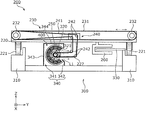
- FIG. 2 is a cross-sectional view of the article conveyance device according to the embodiment, which is cut in a vehicle width direction of the conveyance cart.
- FIG. 3 is a plan view schematically showing a schematic configuration of the ground-side facility according to the embodiment.
- FIG. 4 is a block diagram illustrating a functional configuration of the article transport device according to the embodiment.
- FIG. 5 is a plan view schematically illustrating a schematic configuration of the ground-side facility according to the first modification.
- FIG. 6 is a cross-sectional view of the article transporting device according to Modification 2 cut in the vehicle width direction of the transport trolley.
- FIG. 7 is a cross-sectional view of the article transporting device according to Modification 3 cut in the vehicle width direction of the transport trolley.
- FIG. 1 is a perspective view for explaining the configuration of the article transport device according to the embodiment.
- FIG. 2 is a cross-sectional view of the article conveyance device according to the embodiment, which is cut in a vehicle width direction of the conveyance cart.
- the article transport device 100 includes a plurality of trolleys 200 traveling along a predetermined traveling path R, and a ground-side facility 300 having a pair of traveling rails 310 that define the traveling path R.
- Each of the plurality of trolleys 200 is independently controlled by a ground primary linear motor system including a second stator 330 disposed on a predetermined traveling path R and a second movable element 260 of the trolley 200. It travels so that it can be stopped or accelerated or decelerated.
- the cart 200 is a transport cart that travels along the travel path R by traveling on a pair of travel rails 310.
- the carriage 200 includes a carriage main body 220, a transfer mechanism 230, a drive transmission mechanism 240, a first movable element 250, a second movable element 260, and a detected part 270 (see FIG. 4).
- the bogie main body 220 is provided with a plurality of wheels 221 for traveling on a pair of traveling rails 310.
- the carriage main body 220 is provided with a transfer mechanism 230, a drive transmission mechanism 240, a first movable element 250, a second movable element 260, and a detected part 270.
- the transfer mechanism 230 receives a driving force from a motor 400 described later and transfers the articles in an intersecting direction (Y-axis direction) intersecting with the traveling path R.
- the transfer mechanism 230 transfers the articles in the Y-axis direction. It does not have to be orthogonal.
- the transfer direction by the transfer mechanism 230 may intersect the traveling path R at 45 degrees.
- the transfer mechanism 230 is, for example, a transfer belt conveyor, and is disposed above the carriage body 220.
- the transfer mechanism 230 includes an endless belt 231 and a pair of pulleys 232 around which the endless belt 231 is wound.
- the endless belt 231 rotates following the rotation of one pulley 232 of the pair of pulleys 232.
- the article on the endless belt 231 advances in the transfer direction (Y-axis direction). That is, the transfer mechanism 230 transfers the article 10 from the outside in the Y-axis direction to the upper surface of the carriage 200 (that is, the upper surface of the endless belt 231) by driving the endless belt 231 in the Y-axis direction.
- the article 10 placed on the upper surface of the carriage 200 is transferred from the upper surface to the outside in the Y-axis direction.
- the transfer mechanism 230 is not limited to a belt conveyor, but may be a roller conveyor.
- the drive transmission mechanism 240 transmits a driving force from a motor 400 described later to the transfer mechanism 230.
- the drive transmission mechanism 240 includes an endless belt 241 and a plurality of rollers 242 that rotatably support the endless belt 241.
- the plurality of rollers 242 are attached to a support member 227 provided on the carriage body 220.
- a part of the support member 227 protrudes downward with respect to the bogie main body 220.
- a part of the support member 227 has a shape capable of entering the first stator 320 provided on the ground-side facility 300 in the X-axis direction when the bogie 200 travels on the travel path R.
- a part of the support member 227 has a shape that does not interfere with the first stator 320.
- the endless belt 241 is wound around one pulley 232 of the transfer mechanism 230.
- the endless belt 241 rotates by receiving a driving force from a motor 400 described later, the one pulley 232 also rotates, so that the endless belt 231 of the transfer mechanism 230 rotates.
- the endless belt 241 is, for example, a rubber belt.
- the endless belt 241 is not limited to a rubber belt, and may be a chain.
- the first mover 250 constitutes the motor 400 together with the first stator 320 provided on the ground-side facility 300.
- the first mover 250 operates by the magnetic action given from the first stator 320, and drives the transfer mechanism 230.
- the first mover 250 is a rod-shaped member extending in the traveling direction below the transfer mechanism 230, and is rotatably held with respect to the tip of the support member 227.
- the first mover 250 has a columnar shape whose axis coincides with the axis of rotation, and in a direction in which a magnetic field is generated radially around the axis of rotation when viewed from the axis of rotation, a plurality of permanent magnets Are arranged alternately with S poles and N poles.
- the endless belt 241 of the drive transmission mechanism 240 is wound around the first mover 250. That is, when the first mover 250 is rotated by the magnetic action given from the first stator 320, the endless belt 231 of the transfer mechanism 230 is rotated via the endless belt 241 and one pulley 232.
- the second mover 260 is composed of, for example, a plurality of permanent magnets.
- the plurality of permanent magnets constituting second mover 260 are arranged side by side in the traveling direction of bogie 200.
- the second mover 260 is provided on the lower surface of the bogie main body 220, and has one end in the Y-axis direction open.
- the second mover 260 has a configuration in which a plurality of permanent magnets are arranged in two rows in the Z-axis direction with the opening interposed therebetween.
- a second stator 330 provided in the ground-side facility 300 is arranged.
- the plurality of permanent magnets in a row are arranged on the side facing the second stator 330 such that the north pole and the south pole are alternately oriented.
- the second mover 260 is not limited to the two rows of permanent magnets, but may be formed of one row of permanent magnets. Further, the second mover 260 may be configured by a plurality of rows of permanent magnets arranged in the traveling direction.
- the detected part 270 is, for example, a permanent magnet, and is a member to be detected by the position sensor 350.
- the detected part 270 may not be a permanent magnet, and may be the body of the bogie 200 itself when the position sensor 350 is a sensor using laser light, ultrasonic waves, or an image captured by a camera.
- FIG. 3 is a plan view schematically illustrating a schematic configuration of the ground-side facility 300 according to the embodiment.
- the pair of running rails 310 are illustrated with dot hatching.
- the ground-side facility 300 includes a pair of traveling rails 310, a first stator 320, a second stator 330, a shielding plate 340, and a position sensor 350 (see FIG. 4). And In FIG. 1, illustration of the shielding plate 340 is omitted.
- the traveling rail 310 is a member arranged along a predetermined traveling path R. Specifically, the traveling path R is formed in an oval shape as shown in FIG.
- the traveling rail 310 is two members arranged in a direction orthogonal to the traveling path R and along the traveling path R, and is made of, for example, a metal such as aluminum or an aluminum alloy. Note that the traveling rail 310 may be made of resin.
- the traveling rail 310 intersects with the transport path 810 of the transport device 800 that transports the article 10 and transfers the article 10 to and from the transport apparatus 800.
- the transfer space S is included.
- three transport paths 810 are provided for one travel path R.
- three transfer spaces S are also arranged for one traveling path R, and these are arranged discretely along the traveling path R.
- the number of transfer paths 810 may be other than three, and the transfer space S is also a number corresponding to the number of transfer paths 810 installed. That is, it is sufficient that at least one transfer space S is provided for one travel path R.
- the first stator 320 is a stator for applying a magnetic effect to the first mover 250 of the carriage 200 that has stopped or decelerated and entered the transfer space S to operate the first mover 250. is there.
- a plurality of first stators 320 are discretely provided along the traveling path R. Specifically, each of the plurality of first stators 320 is arranged at a position corresponding to the transfer space S.
- the first stator 320 is arranged at a position surrounding the area of the substantially cylindrical area through which the first mover 250 provided on the carriage 200 passes when the carriage 200 travels.
- the first stator 320 is formed in a substantially cylindrical shape that penetrates in the X-axis direction, and has an opening 321 that is partially opened on the peripheral wall.
- the opening 321 is continuous throughout the first stator 320 in the X-axis direction.
- the first stator 320 is formed in a substantially C shape when viewed in the X-axis direction.
- the first stator 320 is constituted by a plurality of coils arranged in a circumferential direction of a substantially columnar region.
- the first stator 320 has a shape surrounding a range of about 270 degrees around the traveling direction (X-axis direction) of the bogie 200.
- the first stator 320 has a shape in which some side surfaces corresponding to a range of about 90 degrees are removed from the cylindrical side surfaces.
- the first stator 320 is arranged such that the removed cylindrical shape faces the plus side in the Y-axis direction.
- the opening 321 is arranged at a position where the inside of the first stator 320 cannot be seen from the opening 321 when the first stator 320 is viewed from above.
- the top view refers to viewing the first stator 320 from the plus side in the Z-axis direction.
- the second stator 330 is arranged along the traveling path R within the opening of the second mover 260.
- the second stator 330 is composed of a board extending in the horizontal direction along the traveling path R, and a plurality of coils arranged in the extending direction of the board. That is, the plurality of coils substantially function as the second stator 330.
- the plurality of coils constituting the second stator 330 are individually controlled by the controller 500 (see FIG. 4), so that each generates a magnetic field independently.
- the plurality of coils constituting the second stator 330 are individually controlled by the controller 500, so that a magnetic action is applied to the second movable element 260 of the carriage 200 to apply a force in the X-axis direction. I do. Thereby, the bogie 200 runs on the running rail 310.
- the shield plate 340 covers the moving path R1 along which the first mover 250 moves when the carriage 200 runs on the running path R from above.
- the movement path R1 of the first mover 250 is shown by a broken line.
- the shielding plate 340 is provided continuously with respect to the entire movement route R1. The shielding plate 340 prevents the foreign matter from interfering with the first mover 250 by blocking further falling even if the foreign matter falls on the movement route R1.
- the shielding plate 340 includes a first portion 341 and a second portion 342.
- the first portion 341 and the second portion 342 are each formed of a metal such as iron, for example.
- the first part 341 is a part that covers the upper part of the movement route R1.
- the first portion 341 covers the upper part of the first stator 320 at a location corresponding to the transfer space S.
- the first part 341 includes a wall part 343 and a ceiling part 344.
- the wall portion 343 is disposed on the side opposite to the opening 321 side of the first stator 320, and covers the movement route R1 and the side of the first stator 320.
- the ceiling portion 344 is a portion extending in the horizontal direction from the upper portion of the wall portion 343, and covers the movement path R1 and the upper part of the first stator 320.
- the tip of the ceiling portion 344 hangs downward so as not to interfere with the drive transmission mechanism 240 and the support member 227 of the carriage 200.
- at least a part of the opening 321 of the first stator 320 is exposed from the tip of the ceiling 344.
- the second part 342 is arranged on the opening 321 side of the first stator 320.
- the second portion 342 stands upright so as not to interfere with the drive transmission mechanism 240 and the support member 227 of the carriage 200. Thereby, at least a part of the opening 321 of the first stator 320 is exposed from the second portion 342.
- the base end of the second portion 342 is arranged at a position farther from the first stator 320 than the front end of the ceiling 344 in the Y-axis direction.
- the upper end of the second portion 342 is bent toward the first stator 320 side.
- the upper end of the second part 342 is inclined at an angle of 90 degrees or more and less than 180 degrees with respect to the base end of the second part 342.
- the upper end of the second portion 342 overlaps the extension L1 of the tip of the ceiling 344. Since the second portion 342 has such a configuration, even if the foreign matter falls and passes near the ceiling 344, the foreign matter is repelled by the upper end of the second portion 342 to the outside of the shielding plate 340. That is, the structure is such that foreign matter is unlikely to enter the shielding plate 340, so that foreign matter is less likely to interfere with the first stator 320 and the first movable element 250.
- the position sensor 350 is a sensor for detecting the position of each carriage 200.
- the position sensor 350 is, for example, a magnetic sensor, and detects the position of a permanent magnet serving as the detection target 270 provided on each of the carts 200.
- the position sensor 350 does not have to be a magnetic sensor, and may be a sensor using laser light, ultrasonic waves, or the like, or may be a sensor using an image captured by a camera.
- the position sensor 350 is disposed along the traveling path R. Specifically, the position sensor 350 is disposed over a section where the second stator 330 is disposed. Thereby, according to the position of each carriage 200 detected by the position sensor 350, the article transporting apparatus 100 controls the second stator 330 corresponding to the position, thereby controlling the traveling operation of each carriage 200. Can be controlled.
- FIG. 4 is a block diagram showing a functional configuration of the article transport device according to the embodiment.
- the article transport device 100 includes a controller 500, a first stator 320, a second stator 330, a position sensor 350, and a plurality of carts 200.
- the first stator 320, the second stator 330, the position sensor 350, and the plurality of trolleys 200 have been described above, and will not be described. That is, here, only the controller 500 will be described. Although only one bogie 200 is shown in FIG. 3, the other bogies 200 function similarly.
- the controller 500 controls the operation of the primary linear motor system on the ground constituted by the second stator 330 and the second movable element 260 of the carriage 200.
- the controller 500 controls the second stator 330, for example, so that each of the plurality of trolleys 200 stops or decelerates into the transfer space S and enters the transfer space S.
- the controller 500 controls the first stator 320 to transfer the article to and from the transport device 800 via the transfer mechanism 230.
- the controller 500 may control the second stator 330 to cause the plurality of bogies 200 to run in synchronization.
- the controller 500 includes, for example, a processor that executes a predetermined program, and a memory that stores the predetermined program. Further, the controller 500 may be configured by a dedicated circuit.
- the article transport device 100 includes the bogie 200 traveling along the predetermined traveling path R, the ground-side facility 300 having the pair of traveling rails 310 that define the traveling path R, It has.
- the carriage 200 is a transfer mechanism 230 that transfers articles in a transfer space S disposed at a predetermined position on the traveling path R, and a rod-shaped member that extends in the traveling direction below the transfer mechanism 230, A first mover 250 that operates by a magnetic action to drive the transfer mechanism 230; and a drive transmission mechanism 240 that supports the first mover 250 and transmits a driving force from the first mover 250 to the transfer mechanism 230.
- a first stator 320 is provided.
- the first stator 320 is an opening 321 through which the drive transmission mechanism 240 of the carriage 200 located in the transfer space S penetrates, and is an opening for disposing the first movable element 250 in the first stator 320. It has a part 321.
- the opening 321 is arranged at a position where the inside of the first stator 320 cannot be seen from the opening 321 when the first stator 320 is viewed from above.
- the opening 321 of the first stator 320 is arranged at a position where the inside of the first stator 320 cannot be seen from the opening 321 when the first stator 320 is viewed from above. Foreign matter can be prevented from entering the opening 321 of the first stator 320 from above. That is, even if the carriage 200 does not exist above the first stator 320 and the first stator 320 is exposed, the invasion of foreign matter from above can be blocked by the first stator 320 itself. . Therefore, intrusion of foreign matter into the motor 400 including the first stator 320 and the first movable element 250 can be suppressed.
- a plurality of first stators 320 are discretely provided along the traveling path R.
- each first stator 320 itself can block invasion of foreign matter from above. Therefore, invasion of foreign matter into the motor 400 including the first stator 320 and the first movable element 250 can be suppressed.
- a plurality of trolleys 200 are provided, and each of the plurality of trolleys 200 can travel independently.
- each of the plurality of trolleys 200 can independently travel on the travel path R, compared to a case where the entirety of the travel path R is covered by the plurality of connected trolleys 200. Also, the occurrence of the empty trolley 200 can be suppressed.
- the ground-side facility 300 includes a second stator 330 disposed along the travel path R, and the bogie 200 operates by the magnetic action from the second stator 330 to move the bogie 200 along the travel path R. Mover 260 for traveling.
- the second stator 330 disposed along the travel path R, and the second movable element 260 that operates by the magnetic action from the second stator 330 and causes the carriage 200 to travel along the travel path R Even in the article transporting apparatus 100 provided with the above, it is possible to suppress entry of foreign matter into the motor 400 including the first stator 320 and the first movable element 250.
- the ground-side facility 300 also includes a shielding plate 340 that covers the entire movement path R1 along which the first mover 250 moves when the carriage 200 travels on the traveling path R from above.
- the shield plate 340 covers the entire movement path R1 on which the first mover 250 moves, the first mover 250 moving on the movement path R1 is moved by the shield plate 340. Covered. That is, the entry of foreign matter into the moving first movable element 250 is blocked by the shielding plate 340. Accordingly, it is possible to more reliably suppress the entry of foreign matter into the motor 400 including the first stator 320 and the first movable element 250.
- FIG. 5 is a plan view schematically showing a schematic configuration of the ground-side facility 300A according to the first modification.
- a pair of traveling rails 310 are illustrated with dot hatching.
- the ground-side facility 300A includes a shielding plate 340A.
- the shielding plate 340A is divided into a plurality along the traveling path R, and the first stator 320 is exposed from the interval.
- the shielding plate 340A covers the entire area of the movement path R1 of the first movable element 250 where the first stator 320 is not provided from above.
- the ground-side facility 300 covers at least an area where the first stator 320 is not provided in the movement path R1 along which the first movable element 250 moves when the carriage 200 travels on the traveling path R.
- a shielding plate 340 is provided.
- the shielding plate 340 covers at least a region where the first stator 320 is not provided on the moving route R1 along which the first mover 250 moves, the region is covered by the shielding plate 340.
- the moving first movable element 250 is covered by the shielding plate 340. That is, the approach of the foreign object to the moving first movable element 250 is prevented by the shielding plate 340. Accordingly, it is possible to more reliably suppress the entry of foreign matter into the motor 400 including the first stator 320 and the first movable element 250.
- the shielding plate 340 does not need to cover the position directly above the movement route R, and may cover the side or the obliquely upper portion of the movement route R. Further, the shielding plate 340A may be a dummy first stator having no magnetic action.
- FIG. 6 is a cross-sectional view of the article conveying device according to Modification 2 cut in the vehicle width direction of the conveying cart.
- the first stator 320a is arranged such that the opening 321a faces obliquely downward.
- the opening 321a faces a direction inclined 45 degrees to the negative side in the Z-axis direction with respect to the Y-axis direction.
- the inside of the first stator 320a cannot be seen from the opening 321a when the first stator 320a is viewed from above.
- a part of the support member 227a has a shape that does not interfere with the first stator 320a. Specifically, a part of the support member 227a hangs down to almost the same position as the lower end of the first stator 320a. Therefore, in the second modification, the second portion 342 of the shielding plate 340 is removed to prevent interference with the support member 227a.
- FIG. 7 is a cross-sectional view of the article conveying device according to Modification 3 cut in the vehicle width direction of the conveying cart.
- the first stator 320b is arranged such that the direction of the opening 321b faces directly below. Specifically, the opening 321b faces the minus side in the Z-axis direction. Also in this case, when the first stator 320b is viewed from above, the inside of the first stator 320b cannot be seen from the opening 321b.
- a part of the supporting member 227b provided has a shape that does not interfere with the first stator 320b. Specifically, a part of the support member 227b hangs down to almost the same position as the lower end of the first stator 320b. Therefore, in the third modification, the second portion 342 of the shielding plate 340 is removed in order to prevent interference with the support member 227b.
- the opening 321 of the first stator 320 is arranged at a position where the inside of the first stator 320 cannot be seen from the opening 321 when the first stator 320 is viewed from above. Therefore, it is possible to block foreign matter from entering the opening 321 of the first stator 320 from above.
- the traveling rail is configured as an endless path, such as an oval or rectangular path, but is not limited to an annular path.
- ⁇ -shaped paths may be formed. That is, the traveling rail may constitute a path having a partially annular path.
- the present invention is useful as an article transport device or the like that can fully utilize the route on which the transport cart travels as a route for transporting articles.
- Reference Signs List 10 Article 100 Article transport apparatus 200 Cart 220 Cart body 221 Wheels 227, 227a, 227b Support member 230 Transfer mechanism 231, 241 Endless belt 232 Pulley 240 Drive transmission mechanism 242 Roller 250 First mover 260 Second mover 270 Detected Unit 300, 300A Ground-side facility 310 Running rails 320, 320a, 320b First stator 321, 321a, 321b Opening 330 Second stator 340, 340A Shielding plate 341 First part 342 Second part 343 Wall part 344 Ceiling part 350 Position sensor 400 Motor 500 Controller 800 Transport device 810 Transport route L1 Extension line R Travel route R1 Travel route S Transfer space
Landscapes
- Engineering & Computer Science (AREA)
- Mechanical Engineering (AREA)
- Non-Mechanical Conveyors (AREA)
- Linear Motors (AREA)
- Discharge Of Articles From Conveyors (AREA)
- Intermediate Stations On Conveyors (AREA)
- Branching, Merging, And Special Transfer Between Conveyors (AREA)
- Seal Device For Vehicle (AREA)
- Supplying Of Containers To The Packaging Station (AREA)
- Control And Other Processes For Unpacking Of Materials (AREA)
Abstract
物品搬送装置(100)は、所定の走行路(R)に沿って走行する台車(200)と、走行路(R)を画定する一対の走行レール(310)を有する地上側設備(300)と、を備えている。台車(200)は、磁気作用により動作して移載機構(230)を駆動する第一可動子(250)と、第一可動子(250)を支持し、当該第一可動子(250)から移載機構(230)に駆動力を伝達する駆動伝達機構(240)と、を備えている。地上側設備(300)は、台車(200)の第一可動子(250)に対して磁気作用を付与して第一可動子(250)を動作させる第一固定子(320)を備えている。第一固定子(320)は、台車(200)の駆動伝達機構(240)が貫通される開口部(321)を有している。開口部(321)は、第一固定子(320)を上面視した際に当該開口部(321)から第一固定子(320)の内部が見えない位置に配置されている。
Description
本発明は、地上一次リニアモータを利用して物品の搬送を行う物品搬送装置に関する。
従来、移載コンベアを有した搬送台車が、リニアモータにより発生した推力で走行路上を走行する物品搬送装置が知られている(例えば特許文献1参照)。搬送台車には、移載コンベアを駆動するための可動子が搭載されているとともに、走行路における所定位置には、搬送台の可動子に対して磁気作用を付与する固定子が設けられている。つまり、搬送台車が走行路における所定位置に停止又は減速して近づくと、搬送台車側の可動子と、走行路側の固定子とがモータを構成することになり、当該モータの磁気作用によって移載コンベアが駆動する。
ところで、モータの固定子と可動子との間に異物が侵入してしまうと、当該異物によって搬送台車の走行が阻害されてしまうおそれがある。
そこで、本発明の目的は、モータに対する異物の混入を抑制することができる物品搬送装置を提供することである。
上記目的を達成するために、本発明の一態様に係る物品搬送装置は、所定の走行路に沿って走行する台車と、走行路を画定する一対の走行レールを有する地上側設備と、を備え、台車は、走行路における所定位置に配置された移載スペースで物品を移載する移載機構と、移載機構の下方で走行方向に延設された棒状の部材であり、磁気作用により動作して移載機構を駆動する第一可動子と、第一可動子を支持し、当該第一可動子から前記移載機構に駆動力を伝達する駆動伝達機構であって、一対の走行レールの間の空間を貫通する駆動伝達機構と、を備え、地上側設備は、移載スペースに位置する台車の第一可動子に対して磁気作用を付与して当該第一可動子を動作させるため、移載スペースに対応する位置に設けられた第一固定子を備え、第一固定子は、移載スペースに位置した台車の駆動伝達機構が貫通される開口部であって、第一可動子を第一固定子内に配置させるための開口部を有し、開口部は、第一固定子を上面視した際に当該開口部から第一固定子の内部が見えない位置に配置されている。
これによれば、第一固定子の開口部が、第一固定子を上面視した際に当該開口部から第一固定子の内部が見えない位置に配置されているので、第一固定子の開口部に対する上方からの異物侵入を遮ることができる。つまり、第一固定子の上方に台車が存在しておらず、第一固定子が露出していたとしても、第一固定子自体で上方からの異物の侵入を遮ることができる。したがって、第一固定子及び第一可動子からなるモータに対する異物の侵入を抑制することができる。
また、第一固定子は、走行路に沿って離散的に複数設けられている。
これによれば、複数の第一固定子が走行路に沿って離散的に設けられている場合においても、各第一固定子の開口部が上述した位置に配置されている。つまり、各第一固定子自体で上方からの異物の侵入を遮ることができる。したがって、各第一固定子及び第一可動子からなるモータに対する異物の侵入を抑制することができる。
また、台車は複数台設けられており、複数台のそれぞれの台車は、独立して走行自在である。
これによれば、複数台のそれぞれの台車が走行路上を独立して走行自在であるので、複数の連結された台車によって走行路の全体が覆われている場合と比較しても、空き台車の発生を抑制することができる。
また、複数台のそれぞれの台車が走行路上を独立して走行自在であるので、各台車の前後で間隔が空く場合が随時発生する。このため、第一固定子の上方に台車が存在しない状態も多く発生することになるが、上述したように第一固定子自体で上方からの異物の侵入を遮っているので、この場合においても第一固定子及び第一可動子からなるモータに対する異物の侵入を抑制することができる。
また、地上側設備は、走行路に沿って配置された第二固定子を備え、台車は、第二固定子からの磁気作用により動作して台車を走行路に沿って走行させる第二可動子を備える。
これによれば、走行路に沿って配置された第二固定子と、第二固定子からの磁気作用により動作して台車を走行路に沿って走行させる第二可動子とを備えた物品搬送装置であっても、第一固定子及び第一可動子からなるモータに対する異物の侵入を抑制することができる。
また、地上側設備は、走行路を台車が走行する際に、第一可動子が移動する移動経路のうち、少なくとも第一固定子が設けられていない領域を覆う遮蔽板を備える。
これによれば、第一可動子が移動する移動経路であって、少なくとも第一固定子が設けられていない領域を遮蔽板が覆っているので、当該領域を移動中の第一可動子は遮蔽板によって覆われる。つまり、移動中の第一可動子に対する異物の接近が遮蔽板で妨げられる。これにより、第一固定子及び第一可動子からなるモータに対する異物の侵入をより確実に抑制することができる。
本発明の物品搬送装置は、モータに対する異物の混入を抑制することができる。
以下に、本発明の実施形態の物品搬送装置ついて、図面を参照しながら説明する。なお、各図は、模式図であり、必ずしも厳密に図示したものではない。
また、以下で説明する実施の形態は、本発明の一具体例を示すものである。以下の実施の形態で示される数値、形状、材料、構成要素、構成要素の配置位置及び接続形態などは、一例であり、本発明を限定する主旨ではない。また、以下の実施の形態における構成要素のうち、最上位概念を示す独立請求項に記載されていない構成要素については、任意の構成要素として説明される。
[構成]
まず、実施の形態に係る物品搬送装置100の概要を説明する。図1は、実施の形態に係る物品搬送装置の構成を説明するための斜視図である。図2は、実施の形態に係る物品搬送装置を搬送台車の車幅方向に切断した断面図である。
まず、実施の形態に係る物品搬送装置100の概要を説明する。図1は、実施の形態に係る物品搬送装置の構成を説明するための斜視図である。図2は、実施の形態に係る物品搬送装置を搬送台車の車幅方向に切断した断面図である。
物品搬送装置100は、図1及び図2に示すように、所定の走行路Rに沿って走行する複数台の台車200と、走行路Rを画定する一対の走行レール310を有する地上側設備300とを備えている。
複数台の台車200のそれぞれは、所定の走行路R上に配置された第二固定子330と、当該台車200が有する第二可動子260により構成される地上一次リニアモータシステムによって、独立して停止または加減速可能に走行する。
台車200は、一対の走行レール310上を走行することで、走行路Rに沿って走行する搬送台車である。台車200は、台車本体220と、移載機構230と、駆動伝達機構240と、第一可動子250と、第二可動子260と、被検知部270(図4参照)とを備えている。
台車本体220には、一対の走行レール310上を走行するための複数の車輪221が設けられている。台車本体220には、移載機構230と、駆動伝達機構240と、第一可動子250と、第二可動子260と、被検知部270が設置されている。
移載機構230は、後述するモータ400からの駆動力を受けて、走行路Rと交差する交差方向(Y軸方向)に物品を移載する。なお、本実施の形態では、移載機構230は、Y軸方向に物品を移載するが、Y軸方向に限らずに、走行路Rに交差する方向であれば、走行路Rに厳密に直交していなくてもよい。例えば、移載機構230による移載方向は、走行路Rに対して45度で交差していてもよい。
移載機構230は、例えば移載用のベルトコンベアであり、台車本体220の上部に配置されている。移載機構230は、無端ベルト231と、無端ベルト231が巻回された一対のプーリ232とを備えている。一対のプーリ232のうち一方のプーリ232が回転することに追従して無端ベルト231が回転する。これにより、無端ベルト231上の物品が移載方向(Y軸方向)に進行する。つまり、移載機構230は、無端ベルト231がY軸方向に駆動されることで、Y軸方向の外側からの物品10を台車200の上面(つまり無端ベルト231の上面)に移載したり、台車200の上面に載置されている物品10を当該上面からY軸方向の外側へ移載したりする。なお、移載機構230はベルトコンベアに限らずに、ローラコンベアであってもよい。
駆動伝達機構240は、後述するモータ400からの駆動力を移載機構230に伝達する。具体的には、駆動伝達機構240は、無端ベルト241と、この無端ベルト241を回転自在に支持する複数のローラ242とを備えている。複数のローラ242は、台車本体220に設けられた支持部材227に対して取り付けられている。支持部材227の一部は、台車本体220に対して下方に向けて突出している。この支持部材227の一部は、台車200が走行路R上を走行する際に、地上側設備300に備わる第一固定子320内にX軸方向で進入可能な形状となっている。この支持部材227の一部は、第一固定子320に対しては干渉しない形状となっている。
無端ベルト241は、移載機構230の一方のプーリ232に巻回されている。後述するモータ400から駆動力を受けて無端ベルト241が回転すると、一方のプーリ232も回転するため、移載機構230の無端ベルト231が回転するようになっている。無端ベルト241は、例えば、ゴムベルトである。無端ベルト241は、ゴムベルトに限らずに、チェーンであってもよい。
第一可動子250は、地上側設備300に備わる第一固定子320とともにモータ400を構成している。第一可動子250は、第一固定子320から付与された磁気作用により動作し、移載機構230を駆動する。具体的には、第一可動子250は、移載機構230の下方で走行方向に延設された棒状の部材であり、支持部材227の先端部に対して回転自在に保持されている。第一可動子250は、回転軸と軸が一致する円柱形状を有し、回転軸方向から見て回転軸を中心に放射状に磁界を発生する向きで、複数の永久磁石が円柱形状の周方向にS極とN極とが交互に並んで配置されることで構成されている。また、第一可動子250には、駆動伝達機構240の無端ベルト241が巻回されている。つまり、第一可動子250が第一固定子320から付与された磁気作用によって回転すると、無端ベルト241及び一方のプーリ232を介して、移載機構230の無端ベルト231が回転することになる。
第二可動子260は、例えば、複数の永久磁石により構成されている。第二可動子260を構成する複数の永久磁石は、台車200の走行方向に並んで配置される。第二可動子260は、台車本体220の下面に設けられており、そのY軸方向の一端部が開放している。第二可動子260は、複数の永久磁石が開口を挟んでZ軸方向に二列に並ぶ構成となっている。第二可動子260の開口内には、地上側設備300に備わる第二固定子330が配置されている。一列の複数の永久磁石は、第二固定子330に対向する側にN極と、S極とが交互に向いているように配置される。なお、第二可動子260は2列の永久磁石に限らずに、1列の永久磁石により構成されていてもよい。また、第二可動子260は、走行方向に並ぶ複数列の永久磁石により構成されていてもよい。
被検知部270は、例えば、永久磁石であり、位置センサ350により検知されるための部材である。被検知部270は、永久磁石でなくてもよく、位置センサ350がレーザ光や超音波、カメラにより撮像された画像を用いるセンサである場合には、台車200の車体そのものであってもよい。
次に、地上側設備300について説明する。図3は、実施の形態に係る地上側設備300の概略構成を模式的に示す平面図である。図3では、一対の走行レール310に対してはドットハッチングを施して図示している。
図1~図3に示すように、地上側設備300は、一対の走行レール310と、第一固定子320と、第二固定子330と、遮蔽板340と、位置センサ350(図4参照)とを備えている。なお、図1では遮蔽板340の図示を省略している。
走行レール310は、所定の走行路Rに沿って配置される部材である。具体的には、走行路Rは図3に示すように長円形状に形成されている。走行レール310は、走行路Rに直交する方向に並び、走行路Rに沿った2本の部材であり、例えば、アルミニウム、アルミニウム合金などの金属により構成されている。なお、走行レール310は、樹脂により構成されていてもよい。本実施の形態では、図1及び図3に示すように、走行レール310は、物品10を搬送する搬送装置800の搬送経路810と交差し、搬送装置800との間で物品10を移載する移載スペースSを含んでいる。本実施の形態では、一つの走行路Rに対して搬送経路810が三つ設けられている。このため、移載スペースSも一つの走行路Rに対して三つ配置されており、これらが走行路Rに沿って離散的に配置されている。なお、搬送経路810の設置個数は3つ以外であってもよく、移載スペースSも搬送経路810の設置個数に対応した数となる。つまり、移載スペースSは、一つの走行路Rに対して少なくとも一つ設けられていればよい。
第一固定子320は、移載スペースSに停車又は減速して進入した台車200の第一可動子250に対して磁気作用を付与して当該第一可動子250を動作させるための固定子である。第一固定子320は、走行路Rに沿って離散的に複数設けられている。具体的には、複数の第一固定子320のそれぞれは、移載スペースSに対応する位置に配置されている。
第一固定子320は、台車200の走行時において、台車200に備わる第一可動子250が通過する略円柱状の領域うち、当該領域を囲う位置に配置されている。具体的には、第一固定子320は、X軸方向で貫通した略円筒状に形成されており、その周壁の一部が開口した開口部321となっている。開口部321は、第一固定子320におけるX軸方向の全体にわたって連続している。これにより、第一固定子320は、X軸方向視において略C字状に形成されている。第一固定子320は、略円柱状の領域の周方向に並ぶ複数のコイルにより構成されている。
第一固定子320は、台車200の走行方向(X軸方向)周りの約270度の範囲を囲う形状を有する。言い換えると、第一固定子320は、円筒形状の側面のうち、約90度の範囲に相当する一部の側面が取り除かれた形状を有する。第一固定子320は、円筒形状の取り除かれた形状がY軸方向プラス側を向く向きで配置されている。このように、開口部321は、第一固定子320を上面視した際に当該開口部321から第一固定子320の内部が見えない位置に配置されている。ここで、上面視とは、Z軸方向プラス側から第一固定子320を見ることを言う。
この開口部321には、移載スペースSに停車又は減速して進入した台車200の駆動伝達機構240及び支持部材227が貫通される。この状態では、支持部材227で支持された第一可動子250は、第一固定子320内に配置されている。
第二固定子330は、第二可動子260の開口内で走行路Rに沿うように配置されている。具体的には、第二固定子330は、走行路R沿って水平方向に延設した基板と、当該基板の延設方向に並んで配置される複数のコイルとにより構成される。つまり、実質的には、複数のコイルが第二固定子330として機能する。第二固定子330を構成する複数のコイルは、コントローラ500(図4参照)により個別に制御されることで、それぞれが独立して磁界を発生する。このように、第二固定子330を構成する複数のコイルが、コントローラ500により個別に制御されることで、台車200の第二可動子260に磁気作用を与えて、X軸方向に力を付与する。これにより台車200が走行レール310上で走行する。
遮蔽板340は、走行路Rを台車200が走行する際に、第一可動子250が移動する移動経路R1を上方から覆っている。図3では、第一可動子250の移動経路R1は破線で図示している。図3に示すように、遮蔽板340は、移動経路R1の全体に対して連続して設けられている。遮蔽板340は、移動経路R1に対して異物が落下したとしても、それ以上の落下を遮ることで、異物が第一可動子250に干渉することを防止している。
具体的には、図2に示すように遮蔽板340は、第一部位341と、第二部位342とを備えている。第一部位341及び第二部位342は、それぞれ例えば鉄などの金属によって形成されている。
第一部位341は、移動経路R1の上方を覆う部位である。第一部位341は、移載スペースSに対応する箇所では、第一固定子320の上方を覆っている。第一部位341は、壁部343と、天井部344とを備えている。壁部343は、第一固定子320の開口部321側とは反対側に配置されており、移動経路R1及び第一固定子320の側方を覆っている。天井部344は、壁部343の上部から水平方向に延設された部位であり、移動経路R1及び第一固定子320の上方を覆っている。天井部344の先端部は、台車200の駆動伝達機構240及び支持部材227に干渉しない程度に、下方に向けて垂れ下がっている。これにより、第一固定子320の開口部321は、その少なくとも一部が天井部344の先端部から露出している。
第二部位342は、第一固定子320の開口部321側に配置されている。第二部位342は、台車200の駆動伝達機構240及び支持部材227に干渉しない程度に、上方に向けて立設している。これにより、第一固定子320の開口部321は、その少なくとも一部が第二部位342から露出している。
第二部位342の基端部は、Y軸方向において、天井部344の先端部よりも第一固定子320から離れた位置に配置されている。第二部位342の上端部は、第一固定子320側に向けて屈曲している。具体的には、第二部位342の上端部は、第二部位342の基端部に対して90度以上、180度未満の角度で傾斜している。また、第二部位342の上端部は、天井部344の先端部の延長線L1上に重なっている。第二部位342がこのような構成であるので、異物が落下し、天井部344の近傍を通過したとしても、第二部位342の上端部によって異物が遮蔽板340外へと弾かれる。つまり、遮蔽板340内に異物が侵入しにくい構成となっているので、第一固定子320及び第一可動子250に対して、より異物が干渉しにくくなっている。
位置センサ350は、各台車200の位置を検知するためのセンサである。位置センサ350は、例えば、磁気センサであり、各台車200のそれぞれに設けられた被検知部270としての永久磁石の位置を検知する。位置センサ350は、磁気センサでなくてもよく、レーザ光や超音波などを用いたセンサであってもよいし、カメラにより撮像した画像を用いたセンサであってもよい。
位置センサ350は、走行路R上に沿って配置されている。具体的には、位置センサ350は、第二固定子330が配置されている区間に亘って配置される。これにより、物品搬送装置100は、位置センサ350により検知された各台車200の位置に応じて、当該位置に対応する第二固定子330を制御することで、各台車200のそれぞれの走行動作を制御することができる。
図4は、実施の形態に係る物品搬送装置の機能的な構成を示すブロック図である。
物品搬送装置100は、コントローラ500と、第一固定子320と、第二固定子330と、位置センサ350と、複数の台車200とを備えている。
第一固定子320と、第二固定子330と、位置センサ350と、複数の台車200については、上述したため、説明を省略する。つまり、ここでは、コントローラ500のみについて説明する。なお、図3では、一つの台車200のみしか図示していないが、他の台車200についても同様に機能する。
コントローラ500は、第二固定子330及び台車200の第二可動子260により構成される地上一次リニアモータシステムの動作を制御する。コントローラ500は、例えば、第二固定子330を制御することで、複数の台車200のそれぞれを、移載スペースSに停車又は減速して進入させる。この状態において、コントローラ500は、第一固定子320を制御することで、搬送装置800との間で移載機構230を介して物品を移載する。
また、コントローラ500は、第二固定子330を制御することで、複数の台車200を同期して走行させてもよい。
コントローラ500は、例えば、所定のプログラムを実行するプロセッサ、及び、所定のプログラムを記憶しているメモリなどにより構成される。また、コントローラ500は、専用回路により構成されてもよい。
[効果など]
以上のように、本実施の形態に係る物品搬送装置100は、所定の走行路Rに沿って走行する台車200と、走行路Rを画定する一対の走行レール310を有する地上側設備300と、を備えている。台車200は、走行路Rにおける所定位置に配置された移載スペースSで物品を移載する移載機構230と、移載機構230の下方で走行方向に延設された棒状の部材であり、磁気作用により動作して移載機構230を駆動する第一可動子250と、第一可動子250を支持し、当該第一可動子250から移載機構230に駆動力を伝達する駆動伝達機構240であって、一対の走行レール310の間の空間を貫通する駆動伝達機構240と、を備えている。地上側設備300は、移載スペースSに位置した台車200の第一可動子250に対して磁気作用を付与して当該第一可動子250を動作させるため、移載スペースSに対応する位置に設けられた第一固定子320を備えている。第一固定子320は、移載スペースSに位置する台車200の駆動伝達機構240が貫通される開口部321であって、第一可動子250を第一固定子320内に配置させるための開口部321を有している。開口部321は、第一固定子320を上面視した際に当該開口部321から第一固定子320の内部が見えない位置に配置されている。
以上のように、本実施の形態に係る物品搬送装置100は、所定の走行路Rに沿って走行する台車200と、走行路Rを画定する一対の走行レール310を有する地上側設備300と、を備えている。台車200は、走行路Rにおける所定位置に配置された移載スペースSで物品を移載する移載機構230と、移載機構230の下方で走行方向に延設された棒状の部材であり、磁気作用により動作して移載機構230を駆動する第一可動子250と、第一可動子250を支持し、当該第一可動子250から移載機構230に駆動力を伝達する駆動伝達機構240であって、一対の走行レール310の間の空間を貫通する駆動伝達機構240と、を備えている。地上側設備300は、移載スペースSに位置した台車200の第一可動子250に対して磁気作用を付与して当該第一可動子250を動作させるため、移載スペースSに対応する位置に設けられた第一固定子320を備えている。第一固定子320は、移載スペースSに位置する台車200の駆動伝達機構240が貫通される開口部321であって、第一可動子250を第一固定子320内に配置させるための開口部321を有している。開口部321は、第一固定子320を上面視した際に当該開口部321から第一固定子320の内部が見えない位置に配置されている。
これによれば、第一固定子320の開口部321が、第一固定子320を上面視した際に当該開口部321から第一固定子320の内部が見えない位置に配置されているので、第一固定子320の開口部321に対する上方からの異物侵入を遮ることができる。つまり、第一固定子320の上方に台車200が存在しておらず、第一固定子320が露出していたとしても、第一固定子320自体で上方からの異物の侵入を遮ることができる。したがって、第一固定子320及び第一可動子250からなるモータ400に対する異物の侵入を抑制することができる。
また、第一固定子320は、走行路Rに沿って離散的に複数設けられている。
これによれば、複数の第一固定子320が走行路Rに沿って離散的に設けられている場合においても、各第一固定子320の開口部321が上述した位置に配置されている。つまり、各第一固定子320自体で上方からの異物の侵入を遮ることができる。したがって、各第一固定子320及び第一可動子250からなるモータ400に対する異物の侵入を抑制することができる。
また、台車200は複数台設けられており、複数台のそれぞれの台車200は、独立して走行自在である。
これによれば、複数台のそれぞれの台車200が走行路R上を独立して走行自在であるので、複数の連結された台車200によって走行路Rの全体が覆われている場合と比較しても、空き台車200の発生を抑制することができる。
また、複数台のそれぞれの台車200が走行路R上を独立して走行自在であるので、各台車200の前後で間隔が空く場合が随時発生する。このため、第一固定子320の上方に台車200が存在しない状態も多く発生することになるが、上述したように第一固定子320自体で上方からの異物の侵入を遮っているので、この場合においても第一固定子320及び第一可動子250からなるモータ400に対する異物の侵入を抑制することができる。
また、地上側設備300は、走行路Rに沿って配置された第二固定子330を備え、台車200は、第二固定子330からの磁気作用により動作して台車200を走行路Rに沿って走行させる第二可動子260を備える。
これによれば、走行路Rに沿って配置された第二固定子330と、第二固定子330からの磁気作用により動作して台車200を走行路Rに沿って走行させる第二可動子260とを備えた物品搬送装置100であっても、第一固定子320及び第一可動子250からなるモータ400に対する異物の侵入を抑制することができる。
また、地上側設備300は、走行路Rを台車200が走行する際に、第一可動子250が移動する移動経路R1の全体を上方から覆う遮蔽板340を備えている。
これによれば、第一可動子250が移動する移動経路R1の全体を遮蔽板340が上方及び側方から覆っているので、移動経路R1を移動中の第一可動子250は遮蔽板340によって覆われる。つまり、移動中の第一可動子250に対する異物の侵入が遮蔽板340で遮られる。これにより、第一固定子320及び第一可動子250からなるモータ400に対する異物の侵入をより確実に抑制することができる。
(変形例1)
上記実施の形態では、遮蔽板340が第一可動子250の移動経路の全体を上方から覆う場合を例示した。しかしながら、遮蔽板340Aは、第一可動子250の移動経路の内、少なくとも第一固定子320が設けられていない領域を上方から覆えばよい。
上記実施の形態では、遮蔽板340が第一可動子250の移動経路の全体を上方から覆う場合を例示した。しかしながら、遮蔽板340Aは、第一可動子250の移動経路の内、少なくとも第一固定子320が設けられていない領域を上方から覆えばよい。
以下、変形例1について詳細に説明する。なお、以降の説明において上記実施の形態と同一の部分には同一の符号を付してその説明を省略する場合がある。
図5は、変形例1に係る地上側設備300Aの概略構成を模式的に示す平面図である。図5では、一対の走行レール310に対してはドットハッチングを施して図示している。
図5に示すように、変形例1に係る地上側設備300Aは、遮蔽板340Aを備えている。遮蔽板340Aは、走行路Rに沿って複数に分割されており、その間隔からは第一固定子320が露出している。これにより、遮蔽板340Aは、第一可動子250の移動経路R1のうち、第一固定子320が設けられていない領域の全体を上方から覆っている。
このように、地上側設備300は、走行路Rを台車200が走行する際に、第一可動子250が移動する移動経路R1のうち、少なくとも第一固定子320が設けられていない領域を覆う遮蔽板340を備えている。
これによれば、第一可動子250が移動する移動経路R1であって、少なくとも第一固定子320が設けられていない領域を遮蔽板340が上方及び側方から覆っているので、当該領域を移動中の第一可動子250は遮蔽板340によって覆われる。つまり、移動中の第一可動子250に対する異物の接近が遮蔽板340で妨げられる。これにより、第一固定子320及び第一可動子250からなるモータ400に対する異物の侵入をより確実に抑制することができる。
なお、遮蔽板340は、移動経路Rの直上を覆っていなくても、移動経路Rの側方又は斜め上方を覆っていてもよい。また、遮蔽板340Aは、磁気作用を有さないダミーの第一固定子であってもよい。
(変形例2、3)
上記実施の形態では、開口部321がY軸方向プラス側を向くように第一固定子320が配置されている場合を例示した。しかしながら、開口部321の向きは、第一固定子320を上面視した際に当該開口部321から第一固定子320の内部が見えないのであれば、如何様でもよい。
上記実施の形態では、開口部321がY軸方向プラス側を向くように第一固定子320が配置されている場合を例示した。しかしながら、開口部321の向きは、第一固定子320を上面視した際に当該開口部321から第一固定子320の内部が見えないのであれば、如何様でもよい。
図6は、変形例2に係る物品搬送装置を搬送台車の車幅方向に切断した断面図である。図6に示すように変形例2では、第一固定子320aは、開口部321aの向きが斜め下を向くように配置されている。具体的には、開口部321aは、Y軸方向に対してZ軸方向マイナス側に45度傾いた方向を向いている。この場合においても、第一固定子320aを上面視した際に開口部321aから第一固定子320aの内部が見えない。
なお、この場合においても、支持部材227aの一部は、第一固定子320aに対して干渉しない形状となっている。具体的には支持部材227aの一部は、第一固定子320aの下端部と概ね同じ位置まで垂下している。このため、変形例2においては、支持部材227aとの干渉を防ぐべく、遮蔽板340の第二部位342を取り除いている。
図7は、変形例3に係る物品搬送装置を搬送台車の車幅方向に切断した断面図である。図7に示すように変形例3では、第一固定子320bは、開口部321bの向きが真下を向くように配置されている。具体的には、開口部321bは、Z軸方向マイナス側を向いている。この場合においても、第一固定子320bを上面視した際に開口部321bから第一固定子320bの内部が見えない。
なお、この場合においても、備わる支持部材227bの一部は、第一固定子320bに対して干渉しない形状となっている。具体的には支持部材227bの一部は、第一固定子320bの下端部と概ね同じ位置まで垂下している。このため、変形例3においては、支持部材227bとの干渉を防ぐべく、遮蔽板340の第二部位342を取り除いている。
(その他)
以上、本発明の一つまたは複数の態様に係る物品搬送装置について、実施の形態に基づいて説明したが、本発明は、この実施の形態に限定されるものではない。本発明の趣旨を逸脱しない限り、当業者が思いつく各種変形を本実施の形態に施したものや、異なる実施の形態における構成要素を組み合わせて構築される形態も、本発明の一つまたは複数の態様の範囲内に含まれてもよい。
以上、本発明の一つまたは複数の態様に係る物品搬送装置について、実施の形態に基づいて説明したが、本発明は、この実施の形態に限定されるものではない。本発明の趣旨を逸脱しない限り、当業者が思いつく各種変形を本実施の形態に施したものや、異なる実施の形態における構成要素を組み合わせて構築される形態も、本発明の一つまたは複数の態様の範囲内に含まれてもよい。
例えば、上記実施の形態では、物品搬送装置100が遮蔽板340を備えている場合を例示したが、遮蔽板340は設けられていなくてもよい。遮蔽板340がなくとも、第一固定子320の開口部321が、第一固定子320を上面視した際に当該開口部321から第一固定子320の内部が見えない位置に配置されているので、第一固定子320の開口部321に対する上方からの異物侵入を遮ることができる。
また、上記実施の形態では、走行レールは、無端状の経路として、長円形状や矩形状などの環状の経路を構成するとしたが、環状の経路に限らずに、8の字状の経路や、θ字状の経路を構成していてもよい。つまり、走行レールは、一部に環状の経路を有する経路を構成していてもよい。
本発明は、搬送台車が走行する経路を、物品を搬送する経路として十分に活用できる物品搬送装置などとして有用である。
10 物品
100 物品搬送装置
200 台車
220 台車本体
221 車輪
227、227a、227b 支持部材
230 移載機構
231、241 無端ベルト
232 プーリ
240 駆動伝達機構
242 ローラ
250 第一可動子
260 第二可動子
270 被検知部
300、300A 地上側設備
310 走行レール
320、320a、320b 第一固定子
321、321a、321b 開口部
330 第二固定子
340、340A 遮蔽板
341 第一部位
342 第二部位
343 壁部
344 天井部
350 位置センサ
400 モータ
500 コントローラ
800 搬送装置
810 搬送経路
L1 延長線
R 走行路
R1 移動経路
S 移載スペース
100 物品搬送装置
200 台車
220 台車本体
221 車輪
227、227a、227b 支持部材
230 移載機構
231、241 無端ベルト
232 プーリ
240 駆動伝達機構
242 ローラ
250 第一可動子
260 第二可動子
270 被検知部
300、300A 地上側設備
310 走行レール
320、320a、320b 第一固定子
321、321a、321b 開口部
330 第二固定子
340、340A 遮蔽板
341 第一部位
342 第二部位
343 壁部
344 天井部
350 位置センサ
400 モータ
500 コントローラ
800 搬送装置
810 搬送経路
L1 延長線
R 走行路
R1 移動経路
S 移載スペース
Claims (5)
- 所定の走行路に沿って走行する台車と、
前記走行路を画定する一対の走行レールを有する地上側設備と、を備え、
前記台車は、
前記走行路における所定位置に配置された移載スペースで物品を移載する移載機構と、
前記移載機構の下方で走行方向に延設された棒状の部材であり、磁気作用により動作して前記移載機構を駆動する第一可動子と、
前記第一可動子を支持し、当該第一可動子から前記移載機構に駆動力を伝達する駆動伝達機構であって、前記一対の走行レールの間の空間を貫通する前記駆動伝達機構と、を備え、
前記地上側設備は、前記移載スペースに位置する前記台車の前記第一可動子に対して磁気作用を付与して当該第一可動子を動作させるため、前記移載スペースに対応する位置に設けられた第一固定子を備え、
前記第一固定子は、前記移載スペースに位置した前記台車の前記駆動伝達機構が貫通される開口部であって、前記第一可動子を前記第一固定子内に配置させるための開口部を有し、
前記開口部は、前記第一固定子を上面視した際に当該開口部から前記第一固定子の内部が見えない位置に配置されている
物品搬送装置。 - 前記第一固定子は、前記走行路に沿って離散的に複数設けられている
請求項1に記載の物品搬送装置。 - 前記台車は複数台設けられており、
複数台のそれぞれの前記台車は、独立して走行自在である
請求項1または2に記載の物品搬送装置。 - 前記地上側設備は、前記走行路に沿って配置された第二固定子を備え、
前記台車は、前記第二固定子からの磁気作用により動作して前記台車を前記走行路に沿って走行させる第二可動子を備える
請求項1~3のいずれか一項に記載の物品搬送装置。 - 前記地上側設備は、前記走行路を前記台車が走行する際に、前記第一可動子が移動する移動経路のうち、少なくとも前記第一固定子が設けられていない領域を覆う遮蔽板を備える
請求項1~4のいずれか一項に記載の物品搬送装置。
Priority Applications (3)
| Application Number | Priority Date | Filing Date | Title |
|---|---|---|---|
| KR1020217000010A KR102471376B1 (ko) | 2018-07-23 | 2019-04-15 | 물품 반송 장치 |
| CN201980048631.1A CN112469645B (zh) | 2018-07-23 | 2019-04-15 | 物品搬运装置 |
| US17/261,304 US11305944B2 (en) | 2018-07-23 | 2019-04-15 | Article conveyance apparatus |
Applications Claiming Priority (2)
| Application Number | Priority Date | Filing Date | Title |
|---|---|---|---|
| JP2018137308A JP7192282B2 (ja) | 2018-07-23 | 2018-07-23 | 物品搬送装置 |
| JP2018-137308 | 2018-07-23 |
Publications (1)
| Publication Number | Publication Date |
|---|---|
| WO2020021792A1 true WO2020021792A1 (ja) | 2020-01-30 |
Family
ID=69181426
Family Applications (1)
| Application Number | Title | Priority Date | Filing Date |
|---|---|---|---|
| PCT/JP2019/016109 Ceased WO2020021792A1 (ja) | 2018-07-23 | 2019-04-15 | 物品搬送装置 |
Country Status (6)
| Country | Link |
|---|---|
| US (1) | US11305944B2 (ja) |
| JP (1) | JP7192282B2 (ja) |
| KR (1) | KR102471376B1 (ja) |
| CN (1) | CN112469645B (ja) |
| TW (1) | TWI796506B (ja) |
| WO (1) | WO2020021792A1 (ja) |
Cited By (1)
| Publication number | Priority date | Publication date | Assignee | Title |
|---|---|---|---|---|
| US11458847B2 (en) * | 2017-01-27 | 2022-10-04 | Murata Machinery, Ltd. | Article transferring device |
Families Citing this family (3)
| Publication number | Priority date | Publication date | Assignee | Title |
|---|---|---|---|---|
| JP7559620B2 (ja) | 2021-03-02 | 2024-10-02 | 村田機械株式会社 | 搬送システム |
| WO2022215115A1 (ja) * | 2021-04-05 | 2022-10-13 | 株式会社Fuji | 移動体 |
| JP7752077B2 (ja) * | 2022-03-03 | 2025-10-09 | 住友重機械工業株式会社 | 測位スケール、可動子、駆動装置 |
Citations (6)
| Publication number | Priority date | Publication date | Assignee | Title |
|---|---|---|---|---|
| JPS63176213A (ja) * | 1987-01-16 | 1988-07-20 | Daifuku Co Ltd | 仕分け用搬送装置 |
| JPH0178620U (ja) * | 1987-11-16 | 1989-05-26 | ||
| JPH02295818A (ja) * | 1989-05-09 | 1990-12-06 | Daifuku Co Ltd | 荷搬送装置 |
| JPH03218249A (ja) * | 1990-01-24 | 1991-09-25 | Nippon Seiko Kk | リニアモータ一体型直動案内ユニット |
| JPH09252504A (ja) * | 1996-03-15 | 1997-09-22 | Hitachi Kiden Kogyo Ltd | 磁気浮上式搬送装置 |
| JP2001225943A (ja) * | 2000-02-09 | 2001-08-21 | Toyo Kanetsu Kk | 仕分けコンベヤの制御方法及び仕分けコンベヤ |
Family Cites Families (22)
| Publication number | Priority date | Publication date | Assignee | Title |
|---|---|---|---|---|
| JPS6478620A (en) | 1987-09-18 | 1989-03-24 | Hitachi Cable | Manufacture of steel wire coated with corrosion-resistant zn-alloy |
| NL8902586A (nl) | 1989-10-19 | 1991-05-16 | Vanderlande Ind Nederland | Transportinrichting. |
| JPH05328538A (ja) * | 1992-05-14 | 1993-12-10 | Toshiba Corp | 磁気浮上搬送装置 |
| JPH0654403A (ja) | 1992-07-31 | 1994-02-25 | Daifuku Co Ltd | 無接触給電搬送設備 |
| JPH0721452A (ja) | 1993-06-30 | 1995-01-24 | Toshiba Corp | 自動販売機の制御装置 |
| JPH0790911A (ja) | 1993-09-28 | 1995-04-04 | Toto Ltd | 衛生洗浄装置を備えた水洗式便器における凍結防止構造 |
| ATE304458T1 (de) * | 1997-05-02 | 2005-09-15 | Automation Tooling Syst | Modulares fördersystem mit mehreren beweglichen elementen mit unabhängiger steuerung |
| EP1353867A2 (en) | 2001-01-22 | 2003-10-22 | Crisplant A/S | Sorter conveyor |
| ITMI20020786A1 (it) * | 2002-04-12 | 2003-10-13 | Sandvik Sorting Systems S P A | Dispositivo per trasferire energia meccanica a bordo di un treno di carrelli di una macchina smistatrice |
| ITMI20020785A1 (it) * | 2002-04-12 | 2003-10-13 | Sandvik Sorting Systems S P A | Dispositivo e metodo per trasferire a bordo del treno di carrelli di una macchina smistatrice cross belt l'energia elettrica necessaria al f |
| JP4766521B2 (ja) * | 2006-06-02 | 2011-09-07 | 株式会社日立プラントテクノロジー | 無人搬送台車 |
| JP5567823B2 (ja) * | 2009-11-09 | 2014-08-06 | ヤマハ発動機株式会社 | リニアスケール、リニアモータ、及びリニアモータの制御装置 |
| JP5556896B2 (ja) * | 2010-10-26 | 2014-07-23 | 村田機械株式会社 | 搬送システム |
| JP5912426B2 (ja) * | 2011-11-07 | 2016-04-27 | ヤマハ発動機株式会社 | リニアコンベア |
| JP6094331B2 (ja) * | 2013-03-29 | 2017-03-15 | 株式会社ダイフク | 物品搬送設備 |
| EP3734816A1 (en) * | 2013-05-09 | 2020-11-04 | Rockwell Automation Technologies, Inc. | Controlled motion system having an improved track configuration |
| CN203877400U (zh) * | 2014-01-24 | 2014-10-15 | 欧耀多 | 一种输送小车 |
| DE102014119110A1 (de) * | 2014-12-18 | 2016-06-23 | Weber Maschinenbau Gmbh Breidenbach | Bewegungsvorrichtung |
| JP6616954B2 (ja) * | 2015-03-31 | 2019-12-04 | あおい精機株式会社 | 搬送装置 |
| CN205555419U (zh) * | 2015-12-28 | 2016-09-07 | 沈志伟 | 带有倾翻直卸托盘的自动分拣装置 |
| CN206939725U (zh) * | 2017-05-09 | 2018-01-30 | 东莞市凯铭精密自动化科技有限公司 | 一种刚性连接的循环精确定位的环形生产线 |
| JP7090911B2 (ja) * | 2019-12-24 | 2022-06-27 | 京楽産業.株式会社 | 遊技機 |
-
2018
- 2018-07-23 JP JP2018137308A patent/JP7192282B2/ja active Active
-
2019
- 2019-04-15 CN CN201980048631.1A patent/CN112469645B/zh active Active
- 2019-04-15 KR KR1020217000010A patent/KR102471376B1/ko active Active
- 2019-04-15 WO PCT/JP2019/016109 patent/WO2020021792A1/ja not_active Ceased
- 2019-04-15 US US17/261,304 patent/US11305944B2/en active Active
- 2019-07-18 TW TW108125474A patent/TWI796506B/zh active
Patent Citations (6)
| Publication number | Priority date | Publication date | Assignee | Title |
|---|---|---|---|---|
| JPS63176213A (ja) * | 1987-01-16 | 1988-07-20 | Daifuku Co Ltd | 仕分け用搬送装置 |
| JPH0178620U (ja) * | 1987-11-16 | 1989-05-26 | ||
| JPH02295818A (ja) * | 1989-05-09 | 1990-12-06 | Daifuku Co Ltd | 荷搬送装置 |
| JPH03218249A (ja) * | 1990-01-24 | 1991-09-25 | Nippon Seiko Kk | リニアモータ一体型直動案内ユニット |
| JPH09252504A (ja) * | 1996-03-15 | 1997-09-22 | Hitachi Kiden Kogyo Ltd | 磁気浮上式搬送装置 |
| JP2001225943A (ja) * | 2000-02-09 | 2001-08-21 | Toyo Kanetsu Kk | 仕分けコンベヤの制御方法及び仕分けコンベヤ |
Cited By (1)
| Publication number | Priority date | Publication date | Assignee | Title |
|---|---|---|---|---|
| US11458847B2 (en) * | 2017-01-27 | 2022-10-04 | Murata Machinery, Ltd. | Article transferring device |
Also Published As
| Publication number | Publication date |
|---|---|
| US11305944B2 (en) | 2022-04-19 |
| TWI796506B (zh) | 2023-03-21 |
| JP2020015560A (ja) | 2020-01-30 |
| CN112469645B (zh) | 2022-03-01 |
| KR20210018409A (ko) | 2021-02-17 |
| US20210347577A1 (en) | 2021-11-11 |
| TW202007623A (zh) | 2020-02-16 |
| KR102471376B1 (ko) | 2022-11-28 |
| CN112469645A (zh) | 2021-03-09 |
| JP7192282B2 (ja) | 2022-12-20 |
Similar Documents
| Publication | Publication Date | Title |
|---|---|---|
| CN112469645B (zh) | 物品搬运装置 | |
| KR100682390B1 (ko) | 천정운반차 | |
| US11878867B2 (en) | Lifting and lowering transportation device | |
| KR101163969B1 (ko) | 무인반송대차 | |
| WO2018037762A1 (ja) | 有軌道台車システム、及び有軌道台車 | |
| TW201924996A (zh) | 行走台車 | |
| CN110199470B (zh) | 物品移载装置 | |
| JP2018123003A (ja) | 物品搬送装置 | |
| WO2023281687A1 (ja) | 位置検出器及びリニア搬送装置 | |
| JP4419302B2 (ja) | 搬送設備 | |
| JP5344366B2 (ja) | 搬送システム | |
| EP2691323B1 (en) | System for automated conveying of components through an assembly line | |
| JP2020015561A (ja) | 物品搬送装置 | |
| JP2003267545A (ja) | 荷の搬送方向転向装置 | |
| KR100978079B1 (ko) | 중량물 탑재용 이송 장치 | |
| JP2016027290A (ja) | 天井走行標的装置 | |
| JP2020191704A (ja) | 走行装置 | |
| JP4591694B2 (ja) | 移動体システム | |
| JP3194557U (ja) | 標的装置 | |
| JP2013230900A (ja) | 搬送ライン | |
| JPH05238380A (ja) | 有軌道台車の衝突防止装置 | |
| JP3119238U (ja) | 機械式搬送装置 | |
| JPH03279569A (ja) | 磁気吸引式浮上搬送装置 | |
| JP2005255305A (ja) | 搬送装置の支持構造 | |
| JPS6392204A (ja) | 搬送設備 |
Legal Events
| Date | Code | Title | Description |
|---|---|---|---|
| 121 | Ep: the epo has been informed by wipo that ep was designated in this application |
Ref document number: 19841745 Country of ref document: EP Kind code of ref document: A1 |
|
| ENP | Entry into the national phase |
Ref document number: 20217000010 Country of ref document: KR Kind code of ref document: A |
|
| NENP | Non-entry into the national phase |
Ref country code: DE |
|
| 122 | Ep: pct application non-entry in european phase |
Ref document number: 19841745 Country of ref document: EP Kind code of ref document: A1 |