WO2020003563A1 - 作業車両 - Google Patents
作業車両 Download PDFInfo
- Publication number
- WO2020003563A1 WO2020003563A1 PCT/JP2018/048623 JP2018048623W WO2020003563A1 WO 2020003563 A1 WO2020003563 A1 WO 2020003563A1 JP 2018048623 W JP2018048623 W JP 2018048623W WO 2020003563 A1 WO2020003563 A1 WO 2020003563A1
- Authority
- WO
- WIPO (PCT)
- Prior art keywords
- steering
- vehicle body
- traveling
- unit
- azimuth
- Prior art date
Links
- 238000001514 detection method Methods 0.000 claims description 31
- 230000008859 change Effects 0.000 claims description 9
- 230000007423 decrease Effects 0.000 claims description 9
- 238000010586 diagram Methods 0.000 description 29
- 230000005540 biological transmission Effects 0.000 description 23
- 238000005259 measurement Methods 0.000 description 12
- 230000007246 mechanism Effects 0.000 description 12
- 230000001133 acceleration Effects 0.000 description 8
- 238000006073 displacement reaction Methods 0.000 description 8
- 230000007935 neutral effect Effects 0.000 description 6
- 239000003921 oil Substances 0.000 description 4
- 238000005507 spraying Methods 0.000 description 4
- 244000025254 Cannabis sativa Species 0.000 description 3
- 230000009194 climbing Effects 0.000 description 3
- 230000001174 ascending effect Effects 0.000 description 2
- 238000010276 construction Methods 0.000 description 2
- 238000005520 cutting process Methods 0.000 description 2
- 238000009826 distribution Methods 0.000 description 2
- 239000003337 fertilizer Substances 0.000 description 2
- 238000003306 harvesting Methods 0.000 description 2
- 239000010720 hydraulic oil Substances 0.000 description 2
- 238000000034 method Methods 0.000 description 2
- 239000000575 pesticide Substances 0.000 description 2
- 238000003825 pressing Methods 0.000 description 2
- 238000007493 shaping process Methods 0.000 description 2
- 230000008901 benefit Effects 0.000 description 1
- 239000003086 colorant Substances 0.000 description 1
- 230000003247 decreasing effect Effects 0.000 description 1
- 238000009792 diffusion process Methods 0.000 description 1
- 230000000694 effects Effects 0.000 description 1
- 238000012986 modification Methods 0.000 description 1
- 230000004048 modification Effects 0.000 description 1
- 230000004044 response Effects 0.000 description 1
- 230000035945 sensitivity Effects 0.000 description 1
- 230000007480 spreading Effects 0.000 description 1
- 238000003892 spreading Methods 0.000 description 1
- 230000007704 transition Effects 0.000 description 1
Images


Classifications
-
- G—PHYSICS
- G05—CONTROLLING; REGULATING
- G05D—SYSTEMS FOR CONTROLLING OR REGULATING NON-ELECTRIC VARIABLES
- G05D1/00—Control of position, course, altitude or attitude of land, water, air or space vehicles, e.g. using automatic pilots
- G05D1/0055—Control of position, course, altitude or attitude of land, water, air or space vehicles, e.g. using automatic pilots with safety arrangements
- G05D1/0061—Control of position, course, altitude or attitude of land, water, air or space vehicles, e.g. using automatic pilots with safety arrangements for transition from automatic pilot to manual pilot and vice versa
-
- A—HUMAN NECESSITIES
- A01—AGRICULTURE; FORESTRY; ANIMAL HUSBANDRY; HUNTING; TRAPPING; FISHING
- A01B—SOIL WORKING IN AGRICULTURE OR FORESTRY; PARTS, DETAILS, OR ACCESSORIES OF AGRICULTURAL MACHINES OR IMPLEMENTS, IN GENERAL
- A01B69/00—Steering of agricultural machines or implements; Guiding agricultural machines or implements on a desired track
- A01B69/007—Steering or guiding of agricultural vehicles, e.g. steering of the tractor to keep the plough in the furrow
- A01B69/008—Steering or guiding of agricultural vehicles, e.g. steering of the tractor to keep the plough in the furrow automatic
-
- B—PERFORMING OPERATIONS; TRANSPORTING
- B60—VEHICLES IN GENERAL
- B60K—ARRANGEMENT OR MOUNTING OF PROPULSION UNITS OR OF TRANSMISSIONS IN VEHICLES; ARRANGEMENT OR MOUNTING OF PLURAL DIVERSE PRIME-MOVERS IN VEHICLES; AUXILIARY DRIVES FOR VEHICLES; INSTRUMENTATION OR DASHBOARDS FOR VEHICLES; ARRANGEMENTS IN CONNECTION WITH COOLING, AIR INTAKE, GAS EXHAUST OR FUEL SUPPLY OF PROPULSION UNITS IN VEHICLES
- B60K35/00—Instruments specially adapted for vehicles; Arrangement of instruments in or on vehicles
- B60K35/20—Output arrangements, i.e. from vehicle to user, associated with vehicle functions or specially adapted therefor
- B60K35/21—Output arrangements, i.e. from vehicle to user, associated with vehicle functions or specially adapted therefor using visual output, e.g. blinking lights or matrix displays
- B60K35/22—Display screens
-
- B—PERFORMING OPERATIONS; TRANSPORTING
- B60—VEHICLES IN GENERAL
- B60W—CONJOINT CONTROL OF VEHICLE SUB-UNITS OF DIFFERENT TYPE OR DIFFERENT FUNCTION; CONTROL SYSTEMS SPECIALLY ADAPTED FOR HYBRID VEHICLES; ROAD VEHICLE DRIVE CONTROL SYSTEMS FOR PURPOSES NOT RELATED TO THE CONTROL OF A PARTICULAR SUB-UNIT
- B60W10/00—Conjoint control of vehicle sub-units of different type or different function
- B60W10/20—Conjoint control of vehicle sub-units of different type or different function including control of steering systems
-
- B—PERFORMING OPERATIONS; TRANSPORTING
- B60—VEHICLES IN GENERAL
- B60W—CONJOINT CONTROL OF VEHICLE SUB-UNITS OF DIFFERENT TYPE OR DIFFERENT FUNCTION; CONTROL SYSTEMS SPECIALLY ADAPTED FOR HYBRID VEHICLES; ROAD VEHICLE DRIVE CONTROL SYSTEMS FOR PURPOSES NOT RELATED TO THE CONTROL OF A PARTICULAR SUB-UNIT
- B60W40/00—Estimation or calculation of non-directly measurable driving parameters for road vehicle drive control systems not related to the control of a particular sub unit, e.g. by using mathematical models
- B60W40/02—Estimation or calculation of non-directly measurable driving parameters for road vehicle drive control systems not related to the control of a particular sub unit, e.g. by using mathematical models related to ambient conditions
- B60W40/06—Road conditions
- B60W40/076—Slope angle of the road
-
- B—PERFORMING OPERATIONS; TRANSPORTING
- B60—VEHICLES IN GENERAL
- B60W—CONJOINT CONTROL OF VEHICLE SUB-UNITS OF DIFFERENT TYPE OR DIFFERENT FUNCTION; CONTROL SYSTEMS SPECIALLY ADAPTED FOR HYBRID VEHICLES; ROAD VEHICLE DRIVE CONTROL SYSTEMS FOR PURPOSES NOT RELATED TO THE CONTROL OF A PARTICULAR SUB-UNIT
- B60W50/00—Details of control systems for road vehicle drive control not related to the control of a particular sub-unit, e.g. process diagnostic or vehicle driver interfaces
- B60W50/06—Improving the dynamic response of the control system, e.g. improving the speed of regulation or avoiding hunting or overshoot
-
- B—PERFORMING OPERATIONS; TRANSPORTING
- B60—VEHICLES IN GENERAL
- B60W—CONJOINT CONTROL OF VEHICLE SUB-UNITS OF DIFFERENT TYPE OR DIFFERENT FUNCTION; CONTROL SYSTEMS SPECIALLY ADAPTED FOR HYBRID VEHICLES; ROAD VEHICLE DRIVE CONTROL SYSTEMS FOR PURPOSES NOT RELATED TO THE CONTROL OF A PARTICULAR SUB-UNIT
- B60W50/00—Details of control systems for road vehicle drive control not related to the control of a particular sub-unit, e.g. process diagnostic or vehicle driver interfaces
- B60W50/08—Interaction between the driver and the control system
- B60W50/14—Means for informing the driver, warning the driver or prompting a driver intervention
-
- B—PERFORMING OPERATIONS; TRANSPORTING
- B60—VEHICLES IN GENERAL
- B60W—CONJOINT CONTROL OF VEHICLE SUB-UNITS OF DIFFERENT TYPE OR DIFFERENT FUNCTION; CONTROL SYSTEMS SPECIALLY ADAPTED FOR HYBRID VEHICLES; ROAD VEHICLE DRIVE CONTROL SYSTEMS FOR PURPOSES NOT RELATED TO THE CONTROL OF A PARTICULAR SUB-UNIT
- B60W60/00—Drive control systems specially adapted for autonomous road vehicles
- B60W60/005—Handover processes
- B60W60/0051—Handover processes from occupants to vehicle
-
- B—PERFORMING OPERATIONS; TRANSPORTING
- B60—VEHICLES IN GENERAL
- B60W—CONJOINT CONTROL OF VEHICLE SUB-UNITS OF DIFFERENT TYPE OR DIFFERENT FUNCTION; CONTROL SYSTEMS SPECIALLY ADAPTED FOR HYBRID VEHICLES; ROAD VEHICLE DRIVE CONTROL SYSTEMS FOR PURPOSES NOT RELATED TO THE CONTROL OF A PARTICULAR SUB-UNIT
- B60W60/00—Drive control systems specially adapted for autonomous road vehicles
- B60W60/005—Handover processes
- B60W60/0053—Handover processes from vehicle to occupant
-
- B—PERFORMING OPERATIONS; TRANSPORTING
- B60—VEHICLES IN GENERAL
- B60W—CONJOINT CONTROL OF VEHICLE SUB-UNITS OF DIFFERENT TYPE OR DIFFERENT FUNCTION; CONTROL SYSTEMS SPECIALLY ADAPTED FOR HYBRID VEHICLES; ROAD VEHICLE DRIVE CONTROL SYSTEMS FOR PURPOSES NOT RELATED TO THE CONTROL OF A PARTICULAR SUB-UNIT
- B60W60/00—Drive control systems specially adapted for autonomous road vehicles
- B60W60/005—Handover processes
- B60W60/0059—Estimation of the risk associated with autonomous or manual driving, e.g. situation too complex, sensor failure or driver incapacity
-
- B—PERFORMING OPERATIONS; TRANSPORTING
- B62—LAND VEHICLES FOR TRAVELLING OTHERWISE THAN ON RAILS
- B62D—MOTOR VEHICLES; TRAILERS
- B62D15/00—Steering not otherwise provided for
- B62D15/02—Steering position indicators ; Steering position determination; Steering aids
- B62D15/021—Determination of steering angle
-
- B—PERFORMING OPERATIONS; TRANSPORTING
- B62—LAND VEHICLES FOR TRAVELLING OTHERWISE THAN ON RAILS
- B62D—MOTOR VEHICLES; TRAILERS
- B62D6/00—Arrangements for automatically controlling steering depending on driving conditions sensed and responded to, e.g. control circuits
-
- G—PHYSICS
- G05—CONTROLLING; REGULATING
- G05D—SYSTEMS FOR CONTROLLING OR REGULATING NON-ELECTRIC VARIABLES
- G05D1/00—Control of position, course, altitude or attitude of land, water, air or space vehicles, e.g. using automatic pilots
- G05D1/02—Control of position or course in two dimensions
- G05D1/021—Control of position or course in two dimensions specially adapted to land vehicles
- G05D1/0212—Control of position or course in two dimensions specially adapted to land vehicles with means for defining a desired trajectory
-
- B—PERFORMING OPERATIONS; TRANSPORTING
- B60—VEHICLES IN GENERAL
- B60K—ARRANGEMENT OR MOUNTING OF PROPULSION UNITS OR OF TRANSMISSIONS IN VEHICLES; ARRANGEMENT OR MOUNTING OF PLURAL DIVERSE PRIME-MOVERS IN VEHICLES; AUXILIARY DRIVES FOR VEHICLES; INSTRUMENTATION OR DASHBOARDS FOR VEHICLES; ARRANGEMENTS IN CONNECTION WITH COOLING, AIR INTAKE, GAS EXHAUST OR FUEL SUPPLY OF PROPULSION UNITS IN VEHICLES
- B60K2360/00—Indexing scheme associated with groups B60K35/00 or B60K37/00 relating to details of instruments or dashboards
- B60K2360/16—Type of output information
- B60K2360/172—Driving mode indication
-
- B—PERFORMING OPERATIONS; TRANSPORTING
- B60—VEHICLES IN GENERAL
- B60K—ARRANGEMENT OR MOUNTING OF PROPULSION UNITS OR OF TRANSMISSIONS IN VEHICLES; ARRANGEMENT OR MOUNTING OF PLURAL DIVERSE PRIME-MOVERS IN VEHICLES; AUXILIARY DRIVES FOR VEHICLES; INSTRUMENTATION OR DASHBOARDS FOR VEHICLES; ARRANGEMENTS IN CONNECTION WITH COOLING, AIR INTAKE, GAS EXHAUST OR FUEL SUPPLY OF PROPULSION UNITS IN VEHICLES
- B60K35/00—Instruments specially adapted for vehicles; Arrangement of instruments in or on vehicles
- B60K35/20—Output arrangements, i.e. from vehicle to user, associated with vehicle functions or specially adapted therefor
- B60K35/28—Output arrangements, i.e. from vehicle to user, associated with vehicle functions or specially adapted therefor characterised by the type of the output information, e.g. video entertainment or vehicle dynamics information; characterised by the purpose of the output information, e.g. for attracting the attention of the driver
-
- B—PERFORMING OPERATIONS; TRANSPORTING
- B60—VEHICLES IN GENERAL
- B60W—CONJOINT CONTROL OF VEHICLE SUB-UNITS OF DIFFERENT TYPE OR DIFFERENT FUNCTION; CONTROL SYSTEMS SPECIALLY ADAPTED FOR HYBRID VEHICLES; ROAD VEHICLE DRIVE CONTROL SYSTEMS FOR PURPOSES NOT RELATED TO THE CONTROL OF A PARTICULAR SUB-UNIT
- B60W50/00—Details of control systems for road vehicle drive control not related to the control of a particular sub-unit, e.g. process diagnostic or vehicle driver interfaces
- B60W2050/0001—Details of the control system
- B60W2050/0002—Automatic control, details of type of controller or control system architecture
- B60W2050/0014—Adaptive controllers
-
- B—PERFORMING OPERATIONS; TRANSPORTING
- B60—VEHICLES IN GENERAL
- B60W—CONJOINT CONTROL OF VEHICLE SUB-UNITS OF DIFFERENT TYPE OR DIFFERENT FUNCTION; CONTROL SYSTEMS SPECIALLY ADAPTED FOR HYBRID VEHICLES; ROAD VEHICLE DRIVE CONTROL SYSTEMS FOR PURPOSES NOT RELATED TO THE CONTROL OF A PARTICULAR SUB-UNIT
- B60W50/00—Details of control systems for road vehicle drive control not related to the control of a particular sub-unit, e.g. process diagnostic or vehicle driver interfaces
- B60W50/08—Interaction between the driver and the control system
- B60W50/14—Means for informing the driver, warning the driver or prompting a driver intervention
- B60W2050/146—Display means
-
- B—PERFORMING OPERATIONS; TRANSPORTING
- B60—VEHICLES IN GENERAL
- B60W—CONJOINT CONTROL OF VEHICLE SUB-UNITS OF DIFFERENT TYPE OR DIFFERENT FUNCTION; CONTROL SYSTEMS SPECIALLY ADAPTED FOR HYBRID VEHICLES; ROAD VEHICLE DRIVE CONTROL SYSTEMS FOR PURPOSES NOT RELATED TO THE CONTROL OF A PARTICULAR SUB-UNIT
- B60W2300/00—Indexing codes relating to the type of vehicle
- B60W2300/15—Agricultural vehicles
- B60W2300/152—Tractors
-
- B—PERFORMING OPERATIONS; TRANSPORTING
- B60—VEHICLES IN GENERAL
- B60W—CONJOINT CONTROL OF VEHICLE SUB-UNITS OF DIFFERENT TYPE OR DIFFERENT FUNCTION; CONTROL SYSTEMS SPECIALLY ADAPTED FOR HYBRID VEHICLES; ROAD VEHICLE DRIVE CONTROL SYSTEMS FOR PURPOSES NOT RELATED TO THE CONTROL OF A PARTICULAR SUB-UNIT
- B60W2510/00—Input parameters relating to a particular sub-units
- B60W2510/20—Steering systems
-
- B—PERFORMING OPERATIONS; TRANSPORTING
- B60—VEHICLES IN GENERAL
- B60W—CONJOINT CONTROL OF VEHICLE SUB-UNITS OF DIFFERENT TYPE OR DIFFERENT FUNCTION; CONTROL SYSTEMS SPECIALLY ADAPTED FOR HYBRID VEHICLES; ROAD VEHICLE DRIVE CONTROL SYSTEMS FOR PURPOSES NOT RELATED TO THE CONTROL OF A PARTICULAR SUB-UNIT
- B60W2520/00—Input parameters relating to overall vehicle dynamics
- B60W2520/18—Roll
-
- B—PERFORMING OPERATIONS; TRANSPORTING
- B60—VEHICLES IN GENERAL
- B60W—CONJOINT CONTROL OF VEHICLE SUB-UNITS OF DIFFERENT TYPE OR DIFFERENT FUNCTION; CONTROL SYSTEMS SPECIALLY ADAPTED FOR HYBRID VEHICLES; ROAD VEHICLE DRIVE CONTROL SYSTEMS FOR PURPOSES NOT RELATED TO THE CONTROL OF A PARTICULAR SUB-UNIT
- B60W2540/00—Input parameters relating to occupants
- B60W2540/18—Steering angle
-
- B—PERFORMING OPERATIONS; TRANSPORTING
- B60—VEHICLES IN GENERAL
- B60W—CONJOINT CONTROL OF VEHICLE SUB-UNITS OF DIFFERENT TYPE OR DIFFERENT FUNCTION; CONTROL SYSTEMS SPECIALLY ADAPTED FOR HYBRID VEHICLES; ROAD VEHICLE DRIVE CONTROL SYSTEMS FOR PURPOSES NOT RELATED TO THE CONTROL OF A PARTICULAR SUB-UNIT
- B60W2552/00—Input parameters relating to infrastructure
- B60W2552/15—Road slope, i.e. the inclination of a road segment in the longitudinal direction
-
- B—PERFORMING OPERATIONS; TRANSPORTING
- B60—VEHICLES IN GENERAL
- B60W—CONJOINT CONTROL OF VEHICLE SUB-UNITS OF DIFFERENT TYPE OR DIFFERENT FUNCTION; CONTROL SYSTEMS SPECIALLY ADAPTED FOR HYBRID VEHICLES; ROAD VEHICLE DRIVE CONTROL SYSTEMS FOR PURPOSES NOT RELATED TO THE CONTROL OF A PARTICULAR SUB-UNIT
- B60W2710/00—Output or target parameters relating to a particular sub-units
- B60W2710/20—Steering systems
- B60W2710/207—Steering angle of wheels
-
- B—PERFORMING OPERATIONS; TRANSPORTING
- B60—VEHICLES IN GENERAL
- B60Y—INDEXING SCHEME RELATING TO ASPECTS CROSS-CUTTING VEHICLE TECHNOLOGY
- B60Y2200/00—Type of vehicle
- B60Y2200/20—Off-Road Vehicles
- B60Y2200/22—Agricultural vehicles
-
- B—PERFORMING OPERATIONS; TRANSPORTING
- B60—VEHICLES IN GENERAL
- B60Y—INDEXING SCHEME RELATING TO ASPECTS CROSS-CUTTING VEHICLE TECHNOLOGY
- B60Y2200/00—Type of vehicle
- B60Y2200/20—Off-Road Vehicles
- B60Y2200/22—Agricultural vehicles
- B60Y2200/221—Tractors
-
- B—PERFORMING OPERATIONS; TRANSPORTING
- B62—LAND VEHICLES FOR TRAVELLING OTHERWISE THAN ON RAILS
- B62D—MOTOR VEHICLES; TRAILERS
- B62D1/00—Steering controls, i.e. means for initiating a change of direction of the vehicle
- B62D1/24—Steering controls, i.e. means for initiating a change of direction of the vehicle not vehicle-mounted
- B62D1/28—Steering controls, i.e. means for initiating a change of direction of the vehicle not vehicle-mounted non-mechanical, e.g. following a line or other known markers
-
- B—PERFORMING OPERATIONS; TRANSPORTING
- B62—LAND VEHICLES FOR TRAVELLING OTHERWISE THAN ON RAILS
- B62D—MOTOR VEHICLES; TRAILERS
- B62D15/00—Steering not otherwise provided for
- B62D15/02—Steering position indicators ; Steering position determination; Steering aids
- B62D15/025—Active steering aids, e.g. helping the driver by actively influencing the steering system after environment evaluation
Definitions
- the present invention relates to, for example, a work vehicle.
- Patent Document 1 is known as an agricultural work machine.
- the agricultural working machine disclosed in Patent Document 1 has a traveling machine body capable of switching between manual traveling by manual steering and automatic traveling by automatic steering along a set traveling line set in parallel with a reference traveling line, a manual traveling mode and an automatic traveling mode.
- the agricultural work machine sets the starting point of the reference traveling line after pressing the right instruction button while traveling along the ridge, and sets the end point of the reference traveling line by pressing the left instruction button during traveling. That is, the reference traveling line is set before the automatic steering.
- Patent Literature 1 it is difficult to make the agricultural machine travel along a set traveling line set on a slope. That is, it is difficult to make the agricultural work machine travel along the set travel line while the agricultural work machine is inclined. Also, in automatic traveling, since the agricultural working machine travels along the reference traveling line, the azimuth of the traveling direction of the agricultural working machine and the azimuth of the reference traveling line often coincide with each other immediately before the automatic traveling. If the azimuth of the agricultural work machine is largely deviated, there is a possibility that the behavior of the agricultural working machine at the time of initial traveling is not stable. In particular, in a situation where the agricultural work machine is traveling on a sloped ground or the like, the direction of the farm work machine is likely to change.
- an object of the present invention is to provide a work vehicle that can stably travel when switching from manual steering to automatic steering. Another object of the present invention is to provide a work vehicle that can be easily driven along a scheduled travel line. Another object of the present invention is to provide a work vehicle that can stably perform automatic steering.
- a work vehicle is a steering device having a steering handle, a vehicle body that can travel with one of manual steering by the steering handle, and automatic steering of the steering handle based on a travel reference line,
- a control device that permits the automatic steering based on a plurality of steering angles of the steering device when the vehicle body travels a predetermined distance in the manual steering.
- the work vehicle includes a steering changeover switch that switches any one of the start and end of the automatic steering
- the control device includes a steering angle obtaining unit that obtains the plurality of steering angles, and a plurality of steering angles obtained by the steering angle obtaining unit.
- a steering judging unit for judging whether or not to permit the start of the automatic steering based on the steering angle, and switching of the start of the automatic steering by the steering changeover switch in a state where the automatic steering is judged to be permitted by the steering judging unit.
- an automatic steering control unit that controls the steering device to perform automatic steering when the operation is performed.
- the work vehicle includes a display device that indicates that the start of the automatic steering is determined to be permitted by the steering determination unit.
- the steering determination unit permits the start of the automatic steering when the variation of the plurality of steering angles is within a predetermined range.
- the work vehicle includes a positioning device capable of detecting the position of the vehicle body, and a reference line setting switch that sets the position of the vehicle body detected by the positioning device to a start position and an end position of the traveling reference line. .
- a work vehicle is a steering device that changes a direction of a vehicle body, a tilt detection device that detects a tilt of the vehicle body, a deviation between a planned traveling line and the vehicle body, and a predetermined parameter.
- a steering angle calculation unit that calculates a steering angle of the steering device that reduces the deviation
- a steering control unit that controls the steering device based on the steering angle calculated by the steering angle calculation unit
- a parameter correction unit that corrects the parameter applied by the steering angle calculation unit based on the tilt of the vehicle body detected by the tilt detection device.
- the parameter correction unit corrects the parameter when the inclination of the vehicle body detected by the inclination detection device is other than a predetermined value.
- the parameter correction unit corrects a parameter in a direction in which the steering angle increases, when the inclination of the vehicle body acquired from the inclination detection device indicates an upward direction, and indicates that the inclination of the vehicle body indicates a downward direction. If so, the parameter is corrected in the direction in which the steering angle decreases.
- a work vehicle includes a steering device having a steering handle, a vehicle body that can travel with one of manual steering by the steering handle, and automatic steering of the steering handle based on a travel reference line.
- a positioning device capable of detecting the azimuth of the vehicle body, an inclination detection device detecting the inclination of the vehicle body, and a difference between the azimuth of the vehicle body detected by the positioning device and the azimuth of the travel reference line is within a determination range. If, the automatic steering is permitted, and, if the permission is, a control device that performs the automatic steering by the steering device, and the control device, the control device detects the tilt detection device The determination range is changed according to the inclination of the vehicle body.
- the control device changes a lower limit value of the determination range according to the inclination of the vehicle body when the vehicle body is inclined such that one side in the width direction of the vehicle body is higher than the other side in the width direction. .
- the control device sets an upper limit value of the determination range smaller than a predetermined upper limit value of a standard range.
- the control device changes an upper limit value of the determination range according to the inclination of the vehicle body when the vehicle body is inclined such that one side in the width direction of the vehicle body is lower than the other side in the width direction. .
- the control device sets a lower limit value of the determination range to be smaller than a lower limit value of a predetermined standard range.
- the work vehicle includes a steering changeover switch that switches any one of the start and end of the automatic steering.
- the control device is configured to start the automatic steering by the steering changeover switch in a state where the automatic steering is permitted. When the switching is performed, automatic steering by the steering device is started.
- the work vehicle includes a display device that indicates that the azimuth difference between the azimuth of the vehicle body detected by the positioning device and the azimuth of the travel reference line is within a determination range.
- the work vehicle includes a reference line setting switch for setting the position of the vehicle body detected by the positioning device to a start position and an end position of the traveling reference line.
- a work vehicle according to yet another aspect of the present invention includes a steering body, a vehicle body that can travel with one of manual steering by the steering handle, and automatic steering of the steering handle based on a travel reference line;
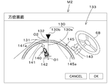
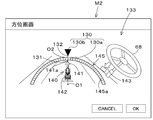
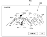
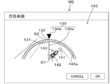
- the display device includes a line direction display unit indicating a line direction and a vehicle direction display unit indicating the direction of the vehicle body.
- the line direction display unit includes a line display unit indicating the traveling reference line, and a mark unit indicating the direction of the traveling line.
- the vehicle body direction display unit includes a direction indicator unit indicating the direction of the vehicle body, and a vehicle body display unit indicating a vehicle body whose display position is changed according to the direction of the vehicle body.
- the display device includes an azimuth scale unit that uses the azimuth of the traveling reference line as a reference point and increases or decreases a value indicating the azimuth in accordance with the distance from the reference point. Includes a mark that indicates the direction of the running line.
- the vehicle body direction display unit includes a direction pointer that indicates the direction of the vehicle body, and the direction pointer unit indicates the direction of the vehicle body on the direction scale unit.
- the display mode of the vehicle direction display unit differs depending on whether the direction difference between the direction of the travel reference line and the direction of the vehicle body is within a predetermined range, or when the direction difference is out of the predetermined range.
- the work vehicle includes a control device that permits the automatic steering when the azimuth difference between the azimuth of the traveling reference line and the azimuth of the vehicle body is within a predetermined range.
- ADVANTAGE OF THE INVENTION According to this invention, it can drive
- FIG. 3 is an explanatory diagram illustrating automatic steering.
- FIG. 3 is an explanatory diagram illustrating a correction amount in a push switch.
- FIG. 4 is an explanatory diagram illustrating a correction amount in a slide switch.
- FIG. 4 is a diagram illustrating a first correction unit and a second correction unit in the push switch.
- FIG. 4 is a diagram illustrating a first correction unit and a second correction unit in the slide switch. This shows a state in which the calculated vehicle body position shifts to the right during automatic steering and straight ahead. This shows a state in which the calculated vehicle body position shifts to the left during straight steering during automatic steering.
- FIG. 4 is an explanatory diagram illustrating control in automatic steering.
- FIG. 4 is an explanatory diagram of conditions for automatic steering.
- FIG. 9 is a diagram illustrating a state in which a plurality of steering angles ⁇ n are obtained. It is an example of a distribution diagram in the case where the variation of a plurality of steering angles ⁇ n is small. It is an example of a distribution diagram in the case where there are many variations in a plurality of steering angles ⁇ n. It is a figure showing an example of an operation screen.
- FIG. 3 is an explanatory diagram illustrating traveling of a tractor on a slope. 1 is an overall view of a tractor.
- FIG. 4 is a diagram illustrating a state in which a tractor is steered in a downward direction without correcting a parameter (control gain).
- FIG. 4 is a diagram illustrating a state in which a tractor is steered in a downward direction by correcting a parameter (control gain).
- FIG. 4 is a diagram illustrating a state in which a tractor is steered in an upward direction without correcting a parameter (control gain).
- FIG. 5 is a diagram illustrating a state in which a tractor is steered in an upward direction by correcting a parameter (control gain).
- FIG. 4 is an explanatory diagram of conditions for automatic steering.
- FIG. 4 is a diagram illustrating a state in which a tractor is steered in a downward direction without correcting a parameter (control gain).
- FIG. 4 is a diagram illustrating a state in which a tractor is steered in a downward direction without correcting a parameter (control gain).
- FIG. 4 is an explanatory diagram of conditions
- FIG. 7 is a diagram illustrating a relationship between an azimuth difference ⁇ F and a determination range G1.
- FIG. 11 is an explanatory diagram illustrating an example in which the lower limit value of a determination range G1 is changed when the tractor is falling to the right.
- FIG. 11 is an explanatory diagram illustrating an example in which the upper limit value of a determination range G1 is changed when the tractor is falling to the left.
- FIG. 9 is an explanatory diagram illustrating an example in which the upper limit value of a determination range G1 is changed when the tractor is falling to the right.
- FIG. 9 is an explanatory diagram illustrating an example in which a lower limit value of a determination range G1 is changed when the tractor is falling to the left. It is a figure showing an example of azimuth screen M2.
- FIG. 11 is an explanatory diagram illustrating an example in which the lower limit value of a determination range G1 is changed when the tractor is falling to the right.
- FIG. 11 is an explanatory diagram illustrating an example
- FIG. 9 is a diagram illustrating an orientation screen M2 when the vehicle orientation F1 and the line orientation F2 match.
- FIG. 9 is a diagram illustrating an orientation screen M2 when the vehicle orientation F1 is slightly shifted leftward with respect to a line orientation F2.
- FIG. 9 is a diagram illustrating an orientation screen M2 when the vehicle orientation F1 is slightly shifted to the right with respect to a line orientation F2.
- FIG. 8 is a diagram illustrating an azimuth screen M2 in a case where a vehicle azimuth azimuth F1 is largely shifted leftward with respect to a line azimuth F2.
- FIG. 9 is a diagram illustrating an azimuth screen M2 in a case where a vehicle azimuth F1 is largely shifted rightward with respect to a line azimuth F2. It is a figure which shows the detail of a scale part.
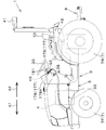
- FIG. 13 is a side view of the work vehicle 1
- FIG. 13 is a plan view of the work vehicle 1.
- the work vehicle 1 is a tractor.
- the work vehicle 1 is not limited to a tractor, and may be an agricultural machine (agricultural vehicle) such as a combine or a transplanter, or a construction machine (construction vehicle) such as a loader work machine.
- agricultural machine agricultural vehicle
- construction machine construction vehicle
- the tractor 1 includes a vehicle body 3, a prime mover 4, and a transmission 5.
- the vehicle body 3 has a traveling device 7 and can travel.
- the traveling device 7 is a device having a front wheel 7F and a rear wheel 7R.
- the front wheel 7F may be of a tire type or a crawler type.
- the rear wheel 7R may be of a tire type or a crawler type.
- the prime mover 4 is a diesel engine, an electric motor, or the like, and in this embodiment, is configured by a diesel engine.
- the transmission 5 can switch the propulsion force of the traveling device 7 by changing the speed, and can switch the traveling device 7 between forward and reverse.
- a driver's seat 10 is provided on the vehicle body 3.
- a working device can be attached to and detached from the connecting portion 8. By connecting the working device to the connecting portion 8, the working device can be pulled by the vehicle body 3.
- the working devices include a tilling device for tilling, a fertilizer spraying device for spraying fertilizer, a pesticide spraying device for spraying pesticides, a harvesting device for harvesting, a cutting device for cutting grass and the like, a diffusion device for spreading grass and the like, and a pasture. And a shaping device for shaping grass and the like.
- the transmission 5 includes a main shaft (propulsion shaft) 5a, a main transmission unit 5b, an auxiliary transmission unit 5c, a shuttle unit 5d, a PTO power transmission unit 5e, a front transmission unit 5f, It has.
- the propulsion shaft 5a is rotatably supported by a housing case (transmission case) of the transmission 5, and power from a crankshaft of the engine 4 is transmitted to the propulsion shaft 5a.
- the main transmission unit 5b has a plurality of gears and a shifter that changes the connection of the gears.
- the main transmission unit 5b changes and outputs (shifts) the rotation input from the propulsion shaft 5a by appropriately changing the connection (engagement) of the plurality of gears with a shifter.
- the auxiliary transmission unit 5c has a plurality of gears and a shifter that changes the connection of the gears, similarly to the main transmission unit 5b.
- the subtransmission unit 5c changes and outputs (shifts) the rotation input from the main transmission unit 5b by appropriately changing the connection (engagement) of the plurality of gears with a shifter.
- the shuttle unit 5d has a shuttle shaft 12 and a forward / reverse switching unit 13.
- the power output from the auxiliary transmission unit 5c is transmitted to the shuttle shaft 12 via gears or the like.
- the forward / reverse switching unit 13 is constituted by, for example, a hydraulic clutch or the like, and switches the rotation direction of the shuttle shaft 12, that is, the forward and backward movements of the tractor 1 by turning on / off the hydraulic clutch.
- the shuttle shaft 12 is connected to a rear wheel differential device 20R.
- the rear wheel differential device 20R rotatably supports a rear axle 21R to which the rear wheel 7R is attached.
- the PTO power transmission unit 5e includes a PTO propulsion shaft 14 and a PTO clutch 15.
- the PTO propulsion shaft 14 is rotatably supported, and can transmit power from the propulsion shaft 5a.
- the PTO propulsion shaft 14 is connected to the PTO shaft 16 via a gear or the like.
- the PTO clutch 15 is composed of, for example, a hydraulic clutch or the like, and the power of the propulsion shaft 5a is transmitted to the PTO propulsion shaft 14 when the hydraulic clutch is turned on and off, and the power of the propulsion shaft 5a is not transmitted to the PTO propulsion shaft 14. Switch to the state.
- the front transmission 5f has a first clutch 17 and a second clutch 18.
- the first clutch 17 and the second clutch can transmit power from the propulsion shaft 5a.
- the power of the shuttle shaft 12 is transmitted via a gear and a transmission shaft.
- Power from the first clutch 17 and the second clutch 18 can be transmitted to the front axle 21F via the front transmission shaft 22.
- the front transmission shaft 22 is connected to a front wheel differential device 20F, and the front wheel differential device 20F rotatably supports a front axle 21F to which the front wheel 7F is attached.
- the first clutch 17 and the second clutch 18 are constituted by a hydraulic clutch or the like.
- An oil passage is connected to the first clutch 17, and the oil passage is connected to a first operating valve 25 to which hydraulic oil discharged from a hydraulic pump is supplied.
- the first clutch 17 switches between a connected state and a disconnected state according to the opening of the first operating valve 25.
- An oil passage is connected to the second clutch 18, and the oil passage is connected to a second operating valve 26.
- the second clutch 18 switches between a connected state and a disconnected state according to the opening of the second operating valve 26.
- the first operating valve 25 and the second operating valve 26 are, for example, two-position switching valves with an electromagnetic valve, and are switched to a connected state or a disconnected state by exciting or demagnetizing a solenoid of the electromagnetic valve.
- the tractor 1 includes a positioning device 40.
- the positioning device 40 can detect its own position (positioning information including latitude and longitude) by a satellite positioning system (positioning satellite) such as D-GPS, GPS, GLONASS, Hokuto, Galileo, and Michibiki. That is, the positioning device 40 receives a satellite signal (position of the positioning satellite, transmission time, correction information, and the like) transmitted from the positioning satellite, and detects a position (for example, latitude and longitude) based on the satellite signal.
- the positioning device 40 includes a receiving device 41 and an inertial measurement device (IMU: Inertial ⁇ Measurement ⁇ Unit) 42.
- IMU Inertial ⁇ Measurement ⁇ Unit
- the receiving device 41 is a device that has an antenna or the like and receives a satellite signal transmitted from a positioning satellite, and is attached to the vehicle body 3 separately from the inertial measuring device 42. In this embodiment, the receiving device 41 is attached to a rope provided in the vehicle body 3.
- the mounting location of the receiving device 41 is not limited to the embodiment.
- the inertial measurement device 42 has an acceleration sensor for detecting acceleration, a gyro sensor for detecting angular velocity, and the like.
- the roll angle, the pitch angle, the yaw angle, and the like of the vehicle body 3 can be detected by the inertial measurement device 42 provided below the vehicle body 3, for example, the driver's seat 10.
- the tractor 1 includes a steering device 11.
- the steering device 11 is a device that can perform manual steering for steering the vehicle body 3 by a driver's operation and automatic steering for automatically steering the vehicle body 3 without a driver's operation.
- the steering device 11 has a steering handle (steering wheel) 30 and a steering shaft (rotary shaft) 31 that rotatably supports the steering handle 30.
- the steering device 11 has an auxiliary mechanism (power steering device) 32.
- the auxiliary mechanism 32 assists the rotation of the steering shaft 31 (the steering handle 30) by hydraulic pressure or the like.
- the auxiliary mechanism 32 includes a hydraulic pump 33, a control valve 34 to which hydraulic oil discharged from the hydraulic pump 33 is supplied, and a steering cylinder 35 operated by the control valve 34.
- the control valve 34 is, for example, a three-position switching valve that can be switched by moving a spool or the like, and switches according to the steering direction (rotation direction) of the steering shaft 31.
- the steering cylinder 35 is connected to an arm (knuckle arm) 36 that changes the direction of the front wheel 7F.
- the switching position and the opening degree of the control valve 34 are switched in accordance with the rotation direction of the steering handle 30, and the control valve 34 is switched.
- the steering direction of the front wheel 7F can be changed by expanding or contracting the steering cylinder 35 to the left or right in accordance with the switching position and the opening degree. That is, the traveling direction of the vehicle body 3 can be changed to the left or right by the manual steering of the steering handle 30.
- a travel reference line L1 is set before performing automatic steering.
- automatic steering can be performed by setting the scheduled travel line L2 parallel to the travel reference line L1.
- steering in the traveling direction of the tractor 1 is automatically performed such that the vehicle body position measured by the positioning device 40 and the planned traveling line L2 coincide with each other.
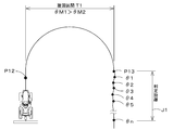
- the tractor 1 (vehicle body 3) is moved to a predetermined position in the field before performing automatic steering (S1), and the driver operates the steering changeover switch 52 provided on the tractor 1 at the predetermined position.
- S2 the vehicle body position measured by the positioning device 40 is set as the start point P10 of the traveling reference line L1 (S3).
- S5 the vehicle body position measured by the positioning device 40 is set as the start point P10 of the traveling reference line L1 (S3).
- the tractor 1 (vehicle body 3) is moved from the starting point P10 of the traveling reference line L1 (S4) and the driver operates the steering changeover switch 52 at a predetermined position (S5)
- the measurement is performed by the positioning device 40.
- the vehicle body position is set to the end point P11 of the traveling reference line L1 (S6). Therefore, a straight line connecting the start point P10 and the end point P11 is set as the traveling reference line L1.
- the tractor 1 (vehicle body 3) is moved to a place different from the place where the travel reference line L1 is set (S7), and the driver operates the steering switch 52. Is performed (S8), a scheduled traveling line L2 that is a straight line parallel to the traveling reference line L1 is set (S9).
- the automatic steering is started, and the traveling direction of the tractor 1 (the vehicle body 3) is changed so as to be along the planned traveling line L2. For example, when the current body position is on the left side of the planned traveling line L2, the front wheels 7F are steered to the right.
- the front wheels 7F are steered. Is steered to the left.
- the traveling speed (vehicle speed) of the tractor 1 can be manually changed by the driver by changing the operation amount of an accelerator member (accelerator, accelerator lever) provided on the tractor 1 or the like. It can be changed by changing the gear position of the transmission.
- the automatic steering can be ended. That is, the end point of the scheduled traveling line L2 can be set by the end of the automatic steering by operating the steering changeover switch 52. That is, the length from the start point to the end point of the scheduled traveling line L2 can be set longer or shorter than the traveling reference line L1. In other words, the scheduled traveling line L2 is not associated with the length of the traveling reference line L1, and the traveling scheduled line L2 allows the vehicle to travel while automatically steering a distance longer than the length of the traveling reference line L1.
- the steering device 11 has an automatic steering mechanism 37.
- the automatic steering mechanism 37 is a mechanism for automatically steering the vehicle body 3, and automatically steers the vehicle body 3 based on the position of the vehicle body 3 (vehicle position) detected by the positioning device 40.
- the automatic steering mechanism 37 includes a steering motor 38 and a gear mechanism 39.
- the steering motor 38 is a motor whose rotation direction, rotation speed, rotation angle, and the like can be controlled based on the vehicle body position.
- the gear mechanism 39 includes a gear provided on the steering shaft 31 and rotating with the steering shaft 31 and a gear provided on the rotating shaft of the steering motor 38 and rotating with the rotating shaft.
- the tractor 1 includes a display device 45.
- the display device 45 is a device capable of displaying various information related to the tractor 1, and is capable of displaying at least operation information of the tractor 1.
- the display device 45 is provided in front of the driver's seat 10.
- the tractor 1 includes a setting switch 51.
- the setting switch 51 is a switch for switching to a setting mode for setting at least before the start of automatic steering.
- the setting mode is a mode in which various settings relating to the automatic steering are performed before the automatic steering is started.
- the setting mode is a mode in which the start point and the end point of the traveling reference line L1 are set.
- the setting switch 51 can be switched ON or OFF. When the setting switch 51 is ON, it outputs a signal that the setting mode is valid, and when it is OFF, it outputs a signal that the setting mode is invalid.
- the setting switch 51 outputs a signal indicating that the setting mode is valid to the display device 45 when the switch is ON, and outputs a signal indicating that the setting mode is invalid to the display device 45 when the switch is OFF.
- the tractor 1 includes a steering changeover switch 52.
- the steering changeover switch 52 is a switch for switching between start and end of automatic steering. Specifically, the steering changeover switch 52 can be switched from the neutral position to the upper, lower, front, and rear, and starts the automatic steering when the setting mode is enabled and the switch is performed from the neutral position to the lower position. When the setting mode is valid and the switch is made upward from the neutral position, the end of the automatic steering is output. Further, when the setting mode is valid and the mode is switched later from the neutral position, the steering changeover switch 52 outputs that the current vehicle body position is set to the starting point P10 of the traveling reference line L1, and the steering changeover switch 52 is output.
- the steering changeover switch 52 outputs that the current vehicle body position is set to the end point P11 of the traveling reference line L1 when the setting mode is enabled and the neutral position is switched forward. That is, the steering changeover switch 52 also functions as a reference line setting switch that sets the start position (start point P10) and end position (end point P11) of the traveling reference line L1. Note that the steering changeover switch 52 may be configured separately from the steering changeover switch 52 that switches the start or end of the automatic steering and the reference line setting switch.
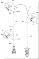
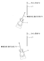
- the tractor 1 includes a correction switch 53.
- the correction switch 53 is a switch for correcting the vehicle body position (latitude and longitude) measured by the positioning device 40. That is, the correction switch 53 is configured to calculate a vehicle position (referred to as a calculated vehicle position) based on a satellite signal (position of a positioning satellite, transmission time, correction information, and the like) and measurement information (acceleration, angular velocity) measured by the inertial measurement device 42. ) Is a switch for correcting
- the correction switch 53 is configured by a push switch that can be pressed or a slide switch that can slide.
- the correction switch 53 is a push switch and a slide switch will be described.
- the correction amount is set based on the number of times the push switch has been operated.
- the number of times the push switch is operated is input to the first control device 60A, and the first control device 60A sets (calculates) a correction amount based on the number of times of operation.
- the correction amount is set based on the operation amount (displacement amount) of the slide switch.
- the operation amount (displacement amount) of the slide switch is input to the first control device 60A, and the first control device 60A sets (calculates) a correction amount based on the displacement amount.
- the method of increasing the correction amount and the rate of increase are not limited to the above-described numerical values.
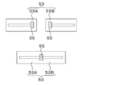
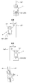
- the correction switch 53 has a first correction unit 53A and a second correction unit 53B.
- the first correction unit 53A is a part for instructing correction of the vehicle body position corresponding to one side in the width direction of the vehicle body 3, that is, the left side.
- the second correction unit 53B is a part for instructing correction of the vehicle body position corresponding to the other side in the width direction of the vehicle body 3, that is, the right side.
- the correction switch 53 when the correction switch 53 is a push switch, the first correction unit 53A and the second correction unit 53B are ON or OFF switches that automatically return each time an operation is performed.
- the switch configuring the first correction unit 53A and the switch configuring the second correction unit 53B are integrated. Note that the switch configuring the first correction unit 53A and the switch configuring the second correction unit 53B may be arranged apart from each other. As shown in FIG. 3A, each time the first correction unit 53A is pressed, the correction amount (left correction amount) corresponding to the left side of the vehicle body 3 increases. Further, each time the second correction unit 53B is pressed, the correction amount (right correction amount) corresponding to the right side of the vehicle body 3 increases.
- the first correction unit 53A and the second correction unit 53B include a knob 55 that moves left or right along the longitudinal direction of the long hole. I have.
- the first correction unit 53A and the second correction unit 53B are arranged apart from each other in the width direction.
- the knob 55 when the knob 55 is gradually displaced leftward from a predetermined reference position, the left correction amount increases in accordance with the displacement amount.
- the knob 55 is gradually displaced rightward from a predetermined reference position, the right correction amount increases in accordance with the displacement amount.
- FIG. 3B when the knob 55 is gradually displaced leftward from a predetermined reference position, the left correction amount increases in accordance with the displacement amount.
- the knob 55 is gradually displaced rightward from a predetermined reference position, the right correction amount increases in accordance with the displacement amount.
- the first correction unit 53A and the second correction unit 53B are integrally formed, the reference position of the knob 55 is set at the center, and from the reference position.
- the left correction amount may be set when moving to the left, and the right correction amount may be set when moving the knob 55 from the intermediate position to the right.
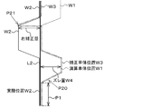
- FIG. 5A shows a state in which the calculated vehicle body position W1 shifts to the right during automatic steering and straight ahead.
- the actual position (actual position W2) of the tractor 1 (the vehicle body 3) matches the calculated vehicle body position W1, and the actual position W2 and the scheduled traveling line When L2 coincides, the tractor 1 travels along the travel scheduled line L2.
- corrected vehicle position W3 calculated vehicle position W1-correction amount.
- the positioning device 40 detects the error.
- the tractor 1 Assuming that the vehicle body position W1 is shifted to the right with respect to the planned traveling line L2 (actual position W2) and the deviation amount W4 is maintained, the tractor 1 has a deviation between the calculated vehicle body position W1 and the planned traveling line L2. Then, the tractor 1 is steered to the left so as to eliminate the deviation amount W4 between the calculated vehicle body position W1 and the planned traveling line L2. Then, the actual position W2 of the tractor 1 is shifted to the planned traveling line L2 by left steering.
- the driver notices that the tractor 1 is deviated from the planned traveling line L2, and steers the second correction unit 53B at the position P21 to increase the right correction amount from zero.
- a right correction amount is added to the calculated vehicle body position W1, and the corrected vehicle body position (corrected vehicle body position) W3 can be made substantially the same as the actual position W2. That is, by setting the right correction amount by the second correction unit 53B, the vehicle body position of the positioning device 40 can be corrected in a direction in which the deviation amount W4 generated near the position P20 is eliminated. As shown in a position P21 in FIG.
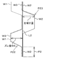
- FIG. 5B shows a state in which the calculated vehicle body position W1 is shifted to the left during automatic steering and straight ahead.
- FIG. 5B when the actual position W2 and the calculated vehicle body position W1 coincide with each other and the actual position W2 coincides with the scheduled traveling line L2 in the state where the automatic steering is started, FIG. Similarly, the tractor 1 travels along the travel scheduled line L2. That is, as in FIG. 5A, in the section P2 where there is no error in the positioning of the positioning device 40, the tractor 1 travels along the planned traveling line L2.
- the calculated vehicle body position W1 and the corrected vehicle body position W3 have the same value.
- the tractor 1 steers the tractor 1 to the right so as to eliminate the deviation amount W5 between the calculated vehicle body position W1 and the planned traveling line L2. Thereafter, it is assumed that the driver notices that the tractor 1 has deviated from the planned traveling line L2, and steers the first correction unit 53A at the position P23 to increase the left correction amount from zero. Then, the left correction amount is added to the calculated vehicle body position W1, and the corrected vehicle body position (corrected vehicle body position) W3 can be made substantially the same as the actual position W2.
- the vehicle body position of the positioning device 40 can be corrected in a direction in which the shift amount W5 generated near the position P22 is eliminated.
- a position P23 in FIG. 5B if the actual position W2 of the tractor 1 is separated to the right from the planned traveling line L2 after the correction of the vehicle body position, the tractor 1 is steered to the left, and The actual position W2 can be made to coincide with the scheduled traveling line L2.
- the outer periphery of the steering shaft 31 is covered with a steering post 180.
- the outer periphery of the steering post 180 is covered by a cover 177.
- the cover 177 is provided in front of the driver's seat 10.
- the cover 177 includes a panel cover 178 and a column cover 179.
- the panel cover 178 supports the display device 45.
- a support portion 178e that supports the display device 45 is provided on the upper plate portion 178a of the panel cover 178.
- the support portion 178e supports the display device 45 in front of the steering shaft 31 and below the steering handle 30.
- the upper plate portion 178a has a mounting surface 178f to which the setting switch 51 and the correction switch 53 are mounted.
- the mounting surface 178f is provided behind the support portion 178e and below the steering handle 30.
- the support portion 178e and the mounting surface 178f are continuous, the support portion 178e is located at the front of the upper plate portion 178a, and the mounting surface 178f is located at the rear of the upper plate portion 178a.
- the setting switch 51 and the correction switch 53 are mounted on the mounting surface 178f.
- the setting switch 51 and the correction switch 53 are arranged around the steering shaft 31.
- the shuttle lever 181 protrudes from the left plate 178b of the panel cover 178.
- the shuttle lever 181 is a member that performs an operation of switching the traveling direction of the vehicle body 3. More specifically, by operating (swinging) the shuttle lever 181 forward, the forward / reverse switching unit 13 outputs a forward power to the traveling device 7, and the traveling direction of the vehicle body 3 is switched to the forward direction.
- the forward / reverse switching unit 13 outputs a reverse power to the traveling device 7, and the traveling direction of the vehicle body 3 is switched to the reverse direction.
- the shuttle lever 181 is at the neutral position, no power is output to the traveling device 7.
- the column cover 179 is disposed below the steering handle 30 and covers the periphery of the upper part of the steering shaft 31.
- the column cover 179 is formed in a substantially rectangular cylindrical shape, and protrudes upward from a mounting surface 178f of the panel cover 178. That is, the mounting surface 178f is provided around the column cover 179. Therefore, the setting switch 51 and the correction switch 53 attached to the attachment surface 178f are arranged around the column cover 179.
- the setting switch 51, the steering changeover switch 52, and the correction switch 53 are arranged around the steering shaft 31.
- the setting switch 51 is arranged on one side (left side) of the steering shaft 31.
- the steering changeover switch 52 is arranged on one side (left side) of the steering shaft 31.
- the steering changeover switch 52 is configured by a swingable lever.
- the steering changeover switch 52 can swing about a base end provided on the steering shaft 31 side as a fulcrum.
- the base end of the steering changeover switch 52 is provided inside the column cover 179.
- the steering changeover switch 52 protrudes to one side (left side) of the column cover 179.
- the correction switch 53 is arranged on the other side (right side) of the steering shaft 31. More specifically, the correction switch 53 is disposed to the right and rear of the steering shaft 31 (obliquely right rear). The correction switch 53 is disposed to the right of and behind the column cover 179 (obliquely right rear) with respect to the positional relationship with the column cover 179. The correction switch 53 is disposed at the right rear of the mounting surface 178f in the positional relationship with the mounting surface 178f of the panel cover 178. By arranging the correction switch 53 behind the inclined mounting surface 178f, a long distance between the correction switch 53 and the steering handle 30 can be ensured. Thereby, unintended operation of the correction switch 53 and steering of the steering handle 30 can be more reliably prevented.
- the setting switch 51, the steering changeover switch 52, and the correction switch 53 are arranged around the steering shaft 31.
- the setting switch 51, the steering changeover switch 52, and the correction switch 53 are located around the steering shaft 31. Therefore, the driver can grasp the position of each switch at a glance.
- the driver can operate each switch while sitting on the driver's seat 10 without changing the posture. Therefore, operability is improved, and erroneous operation can be prevented.
- the harness (wiring) routed from each switch can be shortened.
- the switches may be arranged such that left and right are switched. That is, one side may be left and the other side may be right, or one side may be right and the other side may be left.
- the setting switch 51 and the steering changeover switch 52 may be arranged on the right side of the steering shaft 31, and the correction switch 53 may be arranged on the left side of the steering shaft 31.
- the tractor 1 includes a plurality of control devices 60.
- the plurality of control devices 60 are devices that perform control of the traveling system in the tractor 1, control of the work system, calculation of the vehicle body position, and the like.
- the plurality of control devices 60 are a first control device 60A, a second control device 60B, and a third control device 60C.
- the first control device 60A receives the satellite signal (reception information) received by the reception device 41 and the measurement information (acceleration, angular velocity, etc.) measured by the inertial measurement device 42, and based on the reception information and the measurement information, the vehicle position. Ask for.
- the first control device 60A calculates the calculated vehicle body based on the reception information and the measurement information.
- the position W1 is not corrected, and the calculated vehicle position W1 is determined as the vehicle position to be used during automatic steering.
- the first control device 60A determines the vehicle position based on one of the number of operations of the correction switch 53 and the operation amount (displacement amount) of the correction switch 53.
- a correction amount is set, and a corrected vehicle position W3 obtained by correcting the calculated vehicle position W1 by the correction amount is determined as a vehicle position to be used during automatic steering.
- the first control device 60A sets a control signal based on the vehicle body position (the calculated vehicle body position W1, the corrected vehicle body position W3) and the planned traveling line L2, and outputs the control signal to the second control device 60B.
- the second control device 60B has an automatic steering control unit 200.
- the automatic steering control unit 200 includes an electric / electronic circuit provided in the second control device 60B, a program stored in a CPU, and the like.
- the automatic steering control unit 200 controls the steering motor 38 of the automatic steering mechanism 37 based on the control signal output from the first control device 60A so that the vehicle body 3 travels along the planned traveling line L2.
- the automatic steering control unit 200 maintains the rotation angle of the rotation shaft of the steering motor 38.
- the deviation (positional deviation) between the vehicle body position and the planned traveling line L2 is equal to or greater than the threshold value and the tractor 1 is located on the left side of the planned traveling line L2
- the automatic steering control unit 200 The rotation shaft of the steering motor 38 is rotated so that the steering direction is rightward. That is, the automatic steering control unit 200 sets the rightward steering angle so that the position deviation becomes zero.
- the automatic steering control unit 200 determines that the steering direction of the tractor 1 is left.
- the rotation shaft of the steering motor 38 is rotated so as to be in the direction. That is, the automatic steering control unit 200 sets the leftward steering angle so that the position deviation becomes zero.
- the steering angle of the steering device 11 is changed based on the deviation between the vehicle body position and the planned traveling line L2, but the azimuth of the planned traveling line L2 and the traveling direction of the tractor 1 (vehicle body 3).
- the automatic steering control unit 200 sets the angle ⁇ g to zero (The steering angle may be set such that the vehicle body direction F1 matches the direction of the scheduled traveling line L2). Further, the automatic steering control unit 200 sets the final steering angle in the automatic steering based on the steering angle obtained based on the deviation (position deviation) and the steering angle obtained based on the azimuth (azimuth deviation). You may.
- the setting of the steering angle in the automatic steering in the above-described embodiment is an example, and is not limited.
- the third control device 60C raises and lowers the connecting portion 8 in response to an operation of an operation member provided around the driver's seat 10.
- the first control device 60A, the second control device 60B, and the third control device 60C may be integrated.
- the control of the traveling system, the control of the working system, and the calculation of the vehicle body position are not limited.
- the tractor 1 the vehicle body 3 can be automatically steered by the control device 60.
- the travel reference line L1 After the travel reference line L1 has been set, in order to perform automatic steering, it is necessary to prepare conditions for automatic steering. For example, as shown in FIG. 8, when the tractor 1 is meandering more than a predetermined amount after turning the tractor 1 and before automatic steering (when the vehicle body direction of the tractor 1 is largely different from the traveling reference line L1). In such a case, it is difficult to steer the tractor 1 along the scheduled traveling line L2 parallel to the traveling reference line L1 even if the automatic steering is started. In such a case, the second control device 60B sets the conditions for the automatic steering. Judge that is not complete.
- the second control device 60B includes a steering angle acquisition unit 201 and a steering determination unit 202 in addition to the automatic steering control unit 200.
- the steering angle acquisition unit 201 and the steering determination unit 202 are configured by an electric / electronic circuit provided in the second control device 60B, a program stored in a CPU, and the like.
- the steering angle acquisition unit 201 acquires at least a plurality of steering angles ⁇ n of the steering device 11 during manual steering.
- the steering angle acquisition unit 201 acquires the steering angle ⁇ n detected by the steering angle detection device 205 provided on the vehicle body 3 at predetermined time intervals. As shown in FIG. 9, for example, it is assumed that the steering changeover switch 52 is operated at the position P12 and the automatic steering ends. After the position P12, in the turning section T1, the steering angle ⁇ is a large value, and the steering angle acquisition unit 201 can determine that the tractor 1 is turning, so that the steering angle ⁇ in the turning section T1 is acquired. do not do.
- the steering angle acquisition unit 201 continuously acquires a plurality of steering angles ⁇ n at and after the position P13 where at least the current steering angle ⁇ M1 is equal to or smaller than the turning steering angle (turning determination steering angle ⁇ M2).
- the steering angle acquisition unit 201 acquires, for example, the tractor 1 from the position P13 at a predetermined determination distance J1 or a plurality of steering angles ⁇ n within a predetermined determination time from the position P13.
- the steering determination unit 202 determines whether to permit the start of the automatic steering based on the plurality of steering angles ⁇ n acquired by the steering angle acquisition unit 201.
- the steering determination unit 202 permits the start of the automatic steering when the variation of the plurality of steering angles ⁇ n acquired by the steering angle acquisition unit 201 is within the predetermined range, and the variation of the plurality of steering angles ⁇ n is outside the predetermined range. In this case, automatic steering is not permitted.
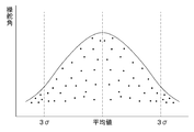
- the steering determination unit 202 obtains a standard deviation and an average value of a plurality of steering angles ⁇ n, and permits the start of the automatic steering when all the steering angles ⁇ n are within 3 ⁇ .
- FIG. 10A for example, the steering determination unit 202 obtains a standard deviation and an average value of a plurality of steering angles ⁇ n, and permits the start of the automatic steering when all the steering angles ⁇ n are within 3 ⁇ .
- FIG. 10A for example, the steering determination unit 202 obtains a standard deviation and an average value of a plurality of steering
- the steering determination unit 202 does not permit the start of the automatic steering when a part of the steering angle ⁇ n is in a region exceeding 3 ⁇ . That is, when it is considered that the steering of the steering handle 30 is stable and the vehicle body 3 is proceeding in the direction of going straight, the steering determination unit 202 permits the automatic steering, and the steering of the steering handle 30 is not stabilized. If it is not determined that the vehicle 3 is traveling straight ahead, the automatic steering is not permitted.
- the steering angle acquisition unit 201 does not acquire the plurality of steering angles ⁇ n during turning. However, instead of this, the steering angle acquisition unit 201 acquires the plurality of steering angles ⁇ n during turning. Then, the steering determination unit 202 excludes the steering angle ⁇ n during turning from the plurality of steering angles ⁇ n acquired by the steering angle acquisition unit 201, and then determines the automatic steering using the excluded steering angle ⁇ n. May go.
- the automatic steering control unit 200 controls the steering device 11 as described above when the start of the automatic steering is switched by the steering changeover switch 52 in a state where it is determined to be permitted by the steering determination unit 202.
- Perform automatic steering The display device 45 can display that the start of the automatic steering is determined to be permitted by the steering determination unit 202. As shown in FIG. 11, when a predetermined operation is performed on the display device 45, the display device 45 displays an operation screen M1.
- the operation screen M1 has an operation display section 61 for displaying operation information.
- the operation display unit 61 includes a rotation display unit 62 that displays the rotation speed of the motor 4 (motor rotation speed) as operation information.
- the rotation display section 62 includes a level display section 63.
- the level display unit 63 is a part that displays the number of revolutions of the prime mover stepwise.
- the level display section 63 includes a scale section 65 and an index section 80.
- the graduation section 65 has, for example, a first line 65A and a plurality of second lines 65B allocated at predetermined intervals along the first line 65A.
- the scale portion 65 has a first line 65A and a third line 65C separated by a predetermined interval.
- the first line 65A and the third line 65C are formed, for example, in a semicircular shape, and one end (for example, left side) has a minimum value and the other end (for example, right side) has a maximum value. .
- the index unit 80 is a bar whose length changes according to the magnitude of the rotation speed of the prime mover.
- the index unit 80 is located, for example, between the first line 65A and the third line 65C, and when the value of the rotation speed of the prime mover is the minimum value of zero, the index unit 80 displays the first line 65A and the third line 65C. In the case where it is located on one end side (left side) and has the shortest length and the value of the prime mover rotation speed is the maximum value, the first line 65A and the first line 65A from one end side (left side) of the first line 65A and the third line 65C.
- the third line 65C extends to the other end side (right side) and has the longest length.
- the rotation display section 62 includes a number display section 64.
- the number display unit 64 displays the number of revolutions of the prime mover by numbers. For example, the rotation display unit 62 is arranged inside the semicircle of the first line 65A and the third line 65C.
- the operation screen M1 has an icon display section 67 for displaying a plurality of icon sections 66.
- the icon display section 67 is a section for displaying various information by the icon section 66.
- the settings related to traveling such as automatic steering, for example, the setting state set in the setting mode is displayed on the icon section 66.
- the icon display section 67 is located at a position different from that of the operation display section 61, and is arranged, for example, above the operation screen M1.
- the plurality of icon sections 66 are a first icon section 66A, a second icon section 66B, a third icon section 66C, a fourth icon section 66D, a fifth icon section 66E, a sixth icon section 66F, and a seventh icon section 66G. .
- the operation screen M1 does not need to include all of the plurality of icon units 66 (66A, 66B, 66C, 66D, 66E, 66F, 66G), and is not limited to the above-described embodiment.
- the first icon section 66A is displayed when a warning has occurred.
- the second icon portion 66B is displayed when the starting point P10 of the traveling reference line L1 has been set.
- the third icon portion 66C is displayed when the end point P11 of the traveling reference line L1 has been set.
- the fourth icon portion 66D is displayed when the automatic steering is permitted.
- the fourth icon part 66D is displayed when the setting mode is valid and the setting of the traveling reference line L1 is completed, and the steering determination unit 202 of the second control device 60B permits the automatic steering.
- the operator can grasp that the automatic steering is permitted. Then, the operator can start the automatic steering by operating the steering changeover switch 52.
- the fifth icon section 66E is displayed when the connecting section 8 is in the up / down state.
- the sixth icon portion 66F is displayed when the vehicle is in the 4WD speedup state.
- the color of the seventh icon portion 66G changes according to the reception sensitivity of the reception signal of the reception device 41.
- the condition for permitting the automatic steering is that the variation of the plurality of steering angles ⁇ n is within a predetermined range.
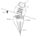
- the azimuth of the tractor 1 (the vehicle body 3) before the automatic steering is determined based on the traveling reference. It may be added to the condition that the azimuth of the line L1 is within a predetermined range. As illustrated in FIG.
- the second control device 60B determines that the variation in the plurality of steering angles ⁇ n is within a predetermined range. Indicates that the automatic steering related to the steering is permitted (first permission), and the azimuth F1 of the tractor 1 (vehicle body 3) calculated by the positioning device 40 or the like and the azimuth (extending direction) of the traveling reference line L1 are within a predetermined range. If, automatic steering related to the azimuth is permitted (second permission). Then, the second control device 60B starts the automatic steering when the first permission and the second permission are aligned and the start of the automatic steering is switched by the operator.
- the work vehicle 1 includes a steering device 11 having a steering handle 30, a vehicle body 3 that can travel by one of manual steering using the steering handle 30, and automatic steering of the steering handle 30 based on the travel reference line L ⁇ b> 1.
- the steering of the steering device 11 is fixed to the left.
- the vehicle may go straight.
- the steering direction of the steering device 11 is steered to the left, the vehicle turns to the left according to the steering direction on a flat ground, but goes straight on an inclined ground, and the steering angle ⁇ is relatively small compared to a flat ground. Large states will continue continuously.
- the automatic steering is determined at a plurality of steering angles ⁇ n. In, straight traveling can be properly determined not only on flat ground but also on sloping ground.
- the work vehicle 1 can be stably driven when switching from manual steering to automatic steering.
- the work vehicle 1 includes a steering changeover switch 52 that switches one of start and end of automatic steering, and the control device 60B obtains the steering angle obtained by the steering angle obtaining unit 201 that obtains a plurality of steering angles.
- a steering determination unit 202 that determines whether to permit the start of automatic steering based on a plurality of steering angles, and switching of the start of automatic steering by the steering changeover switch 52 in a state where the determination by the steering determination unit 202 is permitted is performed.
- an automatic steering control unit 200 that controls the steering device 11 to perform automatic steering when the operation is performed.
- a plurality of steering angles at the time of manual steering can be acquired by the steering angle acquisition unit 201, and it is appropriately determined by the steering determination unit 202 whether automatic steering can be performed based on the plurality of steering angles. Later, the automatic steering can be performed by the automatic steering control unit 200.
- the work vehicle 1 includes a display device 45 that indicates that the start of the automatic steering is determined to be permitted by the steering determination unit 202. According to this, the operator can easily grasp whether or not the start of the automatic steering is permitted only by looking at the display device 45.
- the steering determination unit 202 permits the start of the automatic steering when the variation of the plurality of steering angles is within a predetermined range. According to this, when the steering angle is stable, the switching from the manual steering to the automatic steering, that is, the automatic steering can be started.
- the work vehicle 1 includes a positioning device 40 that can detect the position of the vehicle body 3 and a reference line setting switch that sets the position of the vehicle body 3 detected by the positioning device 40 to the start position and the end position of the traveling reference line L1. Have. According to this, the setting of the traveling reference line L1 can be easily performed by the reference line setting switch. Next, a second embodiment will be described.
- the control device 60 changes the control of the automatic steering based on the inclination of the vehicle body 3.
- the inclination of the vehicle body 3 is detected by an inclination detection device provided on the tractor 1 (the vehicle body 3).
- the inclination detection device is, for example, an inertial measurement device 42 having an acceleration sensor for detecting acceleration, a gyro sensor for detecting angular velocity, and the like, and can detect the tractor 1 (vehicle body 3).
- the tilt detection device may be a device including a plurality of positioning devices 40 (for example, a GPS compass or the like) or may be another device.
- the automatic steering control unit 200 includes a parameter correction unit 200a, a steering angle calculation unit 200b, and a steering control unit 200c.
- the parameter correction unit 200a, the steering angle calculation unit 200b, and the steering control unit 200c are configured by electric / electronic components provided in the control device 60, programs incorporated in the control device 60, and the like.
- the parameter correction unit 200a corrects a parameter applied in automatic steering based on the inclination of the vehicle body 3 detected by the inclination detecting device. For example, when the tractor 1 (vehicle body 3) travels on a flat field, the traveling direction of the tractor 1 can be easily changed following the magnitude of the steering angle of the steering device 11.
- the parameter correction unit 200a corrects the parameter.
- the tractor 1 runs on a field with automatic steering.
- the parameter correction unit 200a is compared with a flat ground having no slope. Change the parameters so that the steering angle increases.
- the parameter correction unit 200a determines that one of the inclination angle (roll angle) in the width direction of the vehicle body 3 and the inclination angle (pitch angle) in the traveling direction of the vehicle body 3 is other than a predetermined value, for example, +5 degrees (deg). In the case described above, the parameter is corrected in a direction to increase the steering angle.
- the parameter correction is performed.
- the unit 200a changes the parameters so that the steering angle is smaller than that on a flat ground without inclination.
- the parameter correction unit 200a sets the parameter in the direction of decreasing the steering angle. to correct.
- the threshold value of the inclination of the vehicle body 3 is an example and is not limited.
- the correction coefficient SG1 is a value changed according to the inclination.
- the reference value SD1 is a fixed value set for obtaining the control gain G1.
- the parameter correction unit 200a sets the correction coefficient SG1 to 1.0, The control gain G1 is obtained. Also, when the inclination of the vehicle body 3 is within the predetermined range, the parameter correction unit 200a sets the correction coefficient SG1 to 1.0. That is, when the inclination of the vehicle body 3 is not large, the parameter correction unit 200a sets the control gain G1 corresponding to the level ground.
- the parameter correction unit 200a increases the correction coefficient SG1 from 1.0 and multiplies the increased correction coefficient SG1 by a reference value (constant) SD1. Changes the control gain G1.
- the parameter correction unit 200a increases the correction coefficient SG1 as the inclination of the vehicle body 3 increases, that is, as the gradient increases.
- the parameter correction unit 200a increases the correction amount of the control gain G1, that is, the increase amount of the correction coefficient SG1 as the inclination of the vehicle body 3 in the upward direction increases.
- the parameter correction unit 200a When the steering is performed in the down direction DN1, the parameter correction unit 200a reduces the correction coefficient SG1 from 1.0 and multiplies the reduced correction coefficient SG1 by a reference value (constant) SD1 to obtain a control gain. Change G1. Note that the parameter correction unit 200a decreases the correction coefficient SG1 as the inclination of the vehicle body 3 in the down direction increases, that is, as the inclination in the down direction increases. In other words, the parameter correction unit 200a increases the correction amount of the control gain G1, that is, the decrease amount of the correction coefficient SG1 as the inclination of the vehicle body 3 in the down direction increases.
- the steering angle calculation unit 200b calculates the steering angle of the steering device 11 for reducing the deviation based on the deviation (position deviation, azimuth deviation) between the planned traveling line L2 and the vehicle body 3 and the parameters. Specifically, based on the position deviation ⁇ L1 between the vehicle body position (calculated vehicle body position W1, corrected vehicle body position W3) and the planned traveling line L2, and the control gain G1 determined by the parameter correction unit 200a, the steering angle in automatic steering is determined. decide.
- the steering angle calculation unit 200b obtains the steering angle by, for example, multiplying the position deviation ⁇ L1 by the control gain G1. Note that the steering angle calculation unit 200b only needs to calculate the steering angle using the control gain G1, and the method of calculating the steering angle is not limited.
- the steering angle calculation unit 200b determines the steering angle in the automatic steering based on the azimuth deviation between the vehicle body azimuth and the planned traveling line L2 and the control gain G1 determined by the parameter correction unit 200a.
- the steering angle calculation unit 200b obtains the steering angle by, for example, multiplying the azimuth deviation by the control gain G1.
- the steering control unit 200c controls the steering device 11 based on the steering angle (calculated steering angle) calculated by the steering angle calculation unit 200b.
- the steering control unit 200c controls the steering motor so that the rightward steering angle of the tractor 1 becomes the calculated steering angle. 38 is controlled.
- the steering control unit 200c determines that the leftward steering angle of the tractor 1 is the calculated steering angle.
- the steering motor 38 is controlled.
- the control gain G1 is changed by the parameter correction unit 200a.
- the steering angle ⁇ 2 in the automatic steering is smaller than the steering angle ⁇ 1 in FIG. 15A. Therefore, even if the running vehicle body 3 receives the external force F in the lowland direction (inclination direction) due to the inclination, the change in the traveling direction of the tractor 1 can be reduced, and the traveling trajectory K becomes the traveling line L2 Can be easily matched.
- the control gain G1 is changed by the parameter correction unit 200a.
- the steering angle ⁇ 3 in the automatic steering is larger than the steering angle ⁇ 1 in FIG. 15A. Therefore, even if the traveling vehicle body 3 receives an external force F in a lowland direction (inclination direction) due to the inclination, a change in the traveling direction of the tractor 1 can be increased, and the traveling trajectory K becomes the traveling line L2 Can be easily matched.
- the width direction has been described with respect to the vehicle body 3, but the same applies to the case where the vehicle body 3 is inclined with respect to the traveling direction of the vehicle body 3 and the case where the vehicle body 3 is ascending or descending.
- the effect can be achieved.
- the inclination angle (pitch angle) with respect to the traveling direction of the vehicle body 3 is equal to or greater than a predetermined value and the vehicle is uphill when viewed from the vehicle body 3, the control gain G1 is increased by the parameter correction unit 200a.
- the steering angle ⁇ 3 according to the pitch angle is larger than the steering angle ⁇ 1 set without performing the correction. Therefore, when the vehicle body 3 is climbing the field, the traveling direction of the vehicle body 3 can be more easily changed as compared with a flat ground.
- the control gain G1 is reduced by the parameter correction unit 200a.
- the steering angle ⁇ 2 according to the pitch angle is smaller than the steering angle ⁇ 1 set without correction. Therefore, when the vehicle body 3 is moving down the field, the traveling direction of the vehicle body 3 can be changed more gently than on a flat ground.
- the work vehicle 1 includes a steering device 11 that changes the direction of the vehicle body 3, an inclination detection device that detects the inclination of the vehicle body 3, and a deviation between the planned traveling line L ⁇ b> 2 and the vehicle body 3 and a predetermined parameter.
- a steering angle calculation unit 200b that calculates the steering angle of the steering device 11 that reduces the deviation
- a steering control unit 200c that controls the steering device 11 based on the steering angle calculated by the steering angle calculation unit 200b
- a tilt detection device a parameter correction unit 200a for correcting a parameter applied by the steering angle calculation unit 200b based on the detected inclination of the vehicle body 3.
- the steering behavior of the vehicle body 3 can be changed according to the inclination of the vehicle body 3. For example, even when the vehicle body 3 is traveling on a slope, the vehicle can easily travel along the planned traveling line L2.
- the parameter correction unit 200a corrects the parameter when the inclination of the vehicle body 3 detected by the inclination detecting device is equal to or larger than a predetermined threshold. According to this, the parameters are corrected in a situation where the inclination of the vehicle body 3 affects the steering, that is, when the vehicle body 3 is equal to or larger than the threshold value.
- a predetermined threshold e.g., a predetermined threshold
- the parameter correction unit 200a corrects the parameter in the direction in which the steering angle increases, and the inclination of the vehicle body 3 indicates the downward direction.
- the parameter is corrected in a direction in which the steering angle decreases.
- the steering angle is increased by correcting the parameter, so that it is possible to eliminate the difficulty of the vehicle body 3 turning due to the influence of climbing.
- the steering angle is reduced by correcting the parameter, so that the vehicle body 3 can be prevented from being excessively bent due to the influence of the descent.
- the parameter correction unit 200a increases the amount of parameter correction as the inclination of the vehicle body 3 acquired from the inclination detection device increases. According to this, the correction amount can be increased according to the inclination and the steering according to the inclination can be performed regardless of whether the vehicle body 3 goes up or down the slope.
- the parameter correction unit 200a corrects a control gain for calculating the steering angle of the steering device 11 as a parameter. According to this, the steering angle can be easily obtained by modifying the control gain SG1.
- the second control device 60B permits automatic steering at least based on the body direction F1 of the tractor 1 (vehicle body 3) and the direction (line direction) F2 of the traveling reference line L1 before automatic steering, that is, in manual steering.
- a determination (judgment) is made.
- the second control device 60B includes an azimuth determination unit 207.
- the azimuth determination unit 207 includes an electric / electronic circuit provided in the second control device 60B, a program stored in a CPU, and the like.
- the azimuth determining unit 207 permits automatic steering when the azimuth difference ⁇ F between the vehicle azimuth F1 and the line azimuth F2 is within the determination range G1, and does not permit automatic steering when the azimuth difference ⁇ F is outside the determination range G1.
- FIG. 18 is a diagram showing a relationship between the azimuth difference ⁇ F and the determination range G1.
- the determination range G1 is centered on a reference line 210 (a reference line 210 where the azimuth difference ⁇ F is zero) where the vehicle body direction F1 and the line direction F2 coincide, and one side (left side) is minus. The other side (right side) is the range indicated by plus.
- the lower limit Gmin of the determination range G1 is on the minus side
- the upper limit Gmax is on the plus side.
- the plus and minus in the determination range G1 are set for convenience, and are not limited to the above-described example.
- the lower limit Gmin and the upper limit Gmax of the determination range G1 are predetermined. If the lower limit Gmin and the upper limit Gmax are considered as absolute values, they are the same value. Therefore, in a state where the tractor 1 is running while maintaining a horizontal state without tilting in the width direction, that is, in a state where the tractor 1 is running on a field which is not tilted, the azimuth difference between the vehicle body direction F1 and the line direction F2. If ⁇ F falls within the determination range G1, the azimuth determination unit 207 permits automatic steering, and does not permit automatic steering if the azimuth difference ⁇ F is out of the determination range G1.
- the second control device 60B determines whether or not to permit the automatic steering based on the azimuth difference ⁇ F and the determination range G1, but in addition to this, the second control device 60B performs the second control.
- the device 60B changes the determination range G1 used for automatic steering according to the inclination of the vehicle body 3.
- the inclination of the vehicle body 3 is detected by an inclination detection device provided on the tractor 1 (the vehicle body 3).
- the inclination detecting device is, for example, an inertial measuring device 42 having an acceleration sensor for detecting acceleration, a gyro sensor for detecting angular velocity, and the like, and can detect the tractor 1 (vehicle body 3).
- the tilt detection device may be a device including a plurality of positioning devices 40 (for example, a GPS compass or the like) or may be another device.
- the azimuth determination unit 207 determines the determination range as shown in FIG. G1 is set in the standard range ST1, and it is determined whether or not to permit automatic steering based on the standard range ST1.
- FIG. 19A when the tractor 1 (vehicle body 3) is inclined such that one side (left side) in the width direction of the tractor 1 (vehicle body 3) is higher than the other side (right side) in the width direction, The two control device 60B sets the lower limit Gmin of the determination range G1 to be larger than the lower limit Gmin indicated by the standard range ST1.
- the azimuth determination unit 207 determines whether to permit the automatic steering based on the determination range G1 in which the lower limit Gmin has increased.
- the lower limit Gmin corresponding to the higher side (one side) of the tractor 1 is increased when looking at the range of the determination range G1.
- the upper limit Gmax of the determination range G1 opposite to the lower limit Gmin be smaller than the upper limit Gmax of the standard range ST1. In other words, when the tractor 1 is inclined downward to the right, the upper limit value Gmax corresponding to the lower side (the other side) of the tractor 1 is reduced.
- the second control device 60B determines the determination range G1.
- the upper limit Gmax is made larger than the upper limit Gmax indicated by the standard range ST1. That is, when the traveling reference line L1 is viewed from the tractor 1 and the traveling reference line L1 is high and the tractor 1 side is low and descends to the left, the upper limit value Gmax of the determination range G1 is increased. In this case, the azimuth determination unit 207 determines whether to permit automatic steering based on the determination range G1 in which the upper limit Gmax has increased.
- the upper limit value Gmax corresponding to the higher side (right side) of the tractor 1 is increased.
- the lower limit Gmin of the determination range G1 opposite to the upper limit Gmax be smaller than the lower limit Gmin of the standard range ST1. In other words, when the tractor 1 is inclined to the left, the lower limit Gmin corresponding to the lower side (one side) of the tractor 1 is reduced.
- the second control device 60B sets the magnitude (inclination amount) of the inclination (the roll angle of the vehicle body 3) of the tractor 1 in the width direction of the vehicle body 3. Accordingly, lower limit Gmin and upper limit Gmax are increased. That is, the second control device 60B increases the amount of increase in the lower limit Gmin or the upper limit Gmax for the standard range ST1 when the amount of inclination is large, and sets the lower limit Gmin or the upper limit for the standard range ST1 when the amount of inclination is small. The increase amount of the value Gmax is reduced.
- the automatic steering control unit 200 controls the steering device 11 as described above when the start of automatic steering is switched by the steering changeover switch 52 in a state where the azimuth determination unit 207 determines that the automatic steering is permitted. Perform automatic steering.
- the display device 45 can display that the start of the automatic steering is determined to be permitted by the azimuth determination unit 207.
- the fourth icon section 66D indicates that the setting mode is valid and the setting of the traveling reference line L1 is completed, and the azimuth determination section 207 of the second control device 60B permits the automatic steering. Displayed when you go. By looking at the fourth icon portion 66D, the operator can grasp that the automatic steering is permitted. Then, the operator can start the automatic steering by operating the steering changeover switch 52.
- the automatic steering is permitted under the condition that the azimuth difference ⁇ F is within a predetermined range.
- the condition is that the steering angle of the steering device 11 is within a predetermined range. May be added. That is, in a situation where the tractor 1 (vehicle body 3) is being steered by manual steering, the second control device 60B permits (first permission) automatic steering related to the azimuth when the azimuth difference ⁇ F is within a predetermined range, When the steering angle ⁇ of the steering device 11 is within a predetermined range, the automatic steering related to the steering is permitted (second permission). Then, the second control device 60B starts the automatic steering when the first permission and the second permission are aligned and the switching of the start of the automatic steering is performed by the operator.
- the work vehicle 1 includes a steering device 11 having a steering handle 30, a vehicle body 3 that can travel by either manual steering using the steering handle 30 or automatic steering of the steering handle 30 based on the travel reference line L ⁇ b> 1, and an orientation of the vehicle body 3.
- a positioning device 40 that can detect F1; a tilt detection device that detects the tilt of the vehicle body 3; and a difference ⁇ F between the azimuth F1 of the vehicle body 3 detected by the positioning device 40 and the azimuth F2 of the traveling reference line L1 is determined in the determination range G1.
- the control device 60B detects the inclination of the vehicle body 3 detected by the inclination detection device.
- the judgment range is changed accordingly.
- the work vehicle 1 vehicle body 3
- the work vehicle 1 turns the traveling direction in the upward direction (the case where the vehicle body direction is turned in the upward direction) and the work vehicle.
- the automatic steering can be appropriately started in accordance with the inclination. That is, even when the vehicle is switched from manual steering to automatic steering even on a slope, the vehicle is driven stably.
- the control device 60B changes the lower limit Gmin of the determination range G1 according to the inclination of the vehicle body 3 when the vehicle body 3 is inclined such that one side in the width direction of the vehicle body 3 is higher than the other side in the width direction.
- Control device 60B changes upper limit Gmax of determination range G1 according to the inclination of vehicle body 3 when vehicle body 3 is inclined such that one side in the width direction of vehicle body 3 is lower than the other side in the width direction. I do.
- the lower limit Gmin corresponding to the high side (one side) of the tractor 1 is increased, or the lower limit Gmin corresponding to the high side (the other side) of the tractor 1 is increased.
- the corresponding upper limit value Gmax can be increased. That is, in the determination range G1, the values (the upper limit Gmax and the lower limit Gmin) on the high side of the work vehicle 1 (the vehicle body 3) are large.
- the azimuth difference between the body direction and the line direction is determined. It is possible to switch to automatic steering after increasing the value. As described above, when the work vehicle 1 starts the automatic steering in the ascending direction, the running immediately after the automatic steering is switched can be stably performed on the slope.
- the control device 60B controls the other side (right side). Is smaller than the predetermined standard range ST1.
- the control device 60B controls the one side (left side). Is smaller than the predetermined standard range ST1.
- the azimuth between the vehicle body direction and the line direction is used. It is possible to switch to automatic steering after reducing the difference. As described above, when the work vehicle 1 starts the automatic steering in the down direction, the running immediately after the automatic steering is switched can be stably performed on the slope.
- the work vehicle 1 includes a steering changeover switch 52 that switches between start and end of the automatic steering.
- the control device 60B switches the start of the automatic steering by the steering changeover switch 52 in a state where the automatic steering is permitted. Is performed, the automatic steering by the steering device 11 is started. According to this, at the timing when the operator wants to start the automatic steering, the start command can be issued by the steering changeover switch 52.
- the work vehicle 1 includes a display device 45 that indicates that the azimuth difference ⁇ F between the azimuth of the vehicle body 3 detected by the positioning device 40 and the azimuth F2 of the traveling reference line L1 is within the determination range G1. According to this, the operator can easily grasp by looking at the display device 45 that the automatic steering can be started.
- the work vehicle 1 includes a reference line setting switch that sets the position of the vehicle body 3 detected by the positioning device 40 to the start position and the end position of the traveling reference line L1. According to this, it is possible to easily set the traveling reference line L1.
- the display device 45 can display the line direction F2 of the traveling reference line L1 and the vehicle body direction F1. As shown in FIG. 20, when a predetermined operation is performed on the display device 45, the display device 45 displays the azimuth screen M2.
- the direction screen M2 includes a line direction display unit 130 and a vehicle direction display unit 140.
- the line direction display unit 130 is a part indicating the line direction F2 of the traveling reference line L1, and includes a line display unit 130a and a mark unit 130b.
- the line display unit 130a is a portion showing the traveling reference line L1 itself in a diagram or the like, and extends from the lower side to the upper side on the field 133 set in the azimuth screen M2.
- the mark portion 130b is a portion indicating the direction of the traveling reference line L1, and is arranged, for example, above the end 131 of the line display portion 130a in the field 133.
- the vertex 132 of the triangle indicates the end 131 of the line display section 130a.
- the vehicle body direction display unit 140 includes a direction pointer 141 that indicates the direction of the vehicle body 3 (vehicle direction F1).
- the direction indicator 141 indicates the direction in which the vehicle body direction F1 is oriented with respect to the line direction F2.
- the direction indicator 141 is formed of, for example, a graphic such as an arrow, and the direction indicator 141 is located on one side or the other side of the line display unit 130a around an origin O1 set on a line of the line display unit 130a. Go to
- the vehicle body direction display unit 140 includes a vehicle body display unit 142 in which the tractor 1 (vehicle body 3) is shown by a graphic.
- the position (display position) of the vehicle body display unit 142 changes in accordance with the azimuth centered on the origin O1 similarly to the azimuth indicator unit 141.
- an orientation pointer 141 is disposed at the front of the vehicle display 142 (the front of the tractor 1), and the vehicle display 142 and the orientation pointer 141 simultaneously swing according to the vehicle orientation F1.
- the tip 141a of the direction indicator 141 and the end 131 of the mark 130b face each other.
- the tip 141a of the direction indicator 141 is located to the left of the line display unit 130a.
- the tip 141a of the direction indicator 141 is located to the right of the line display 130a.
- the azimuth scale unit 145 may be displayed on the azimuth screen M2.
- the azimuth scale 145 is a graduation in which the azimuth difference ⁇ F (a value indicating the azimuth) increases or decreases according to the distance from the reference point O2 with the line direction F2 of the traveling reference line L1 as the reference point O2.
- the azimuth scale 145 has a semicircular shape, and is configured by assigning graduation lines 145a corresponding to the azimuth difference ⁇ F at predetermined intervals along the circumference of the semicircle.
- the end 131 of the mark 130b is indicated.
- the azimuth scale 145 shows a determination range G1. That is, at least two colors are separately colored on the plurality of scale lines 145a of the azimuth scale portion 145, and the plurality of scale lines 145a near the reference point O2 indicate that the values are within the determination range G1.
- a color (in-range color) is colored, and a color (out-of-range color) indicating a value outside the determination range G1 is colored on the plurality of graduation lines 145a at positions away from the reference point O2. Further, as described above, when the determination range G1 is changed according to the inclination of the vehicle body 3, the plurality of graduation lines 145a are set so that the plurality of scale lines 145a correspond to the changed determination range G1. The color changes.
- the azimuth indicator 141 is arranged inside (radially inside) the azimuth scale 145, and indicates the vehicle body azimuth F1 to the azimuth scale 145.
- the azimuth indicator 141 determines whether the azimuth difference ⁇ F between the line azimuth F2 and the vehicle body azimuth F1 is within a predetermined range (within the determination range G1), and where the azimuth difference ⁇ F is outside the predetermined range (out of the determination range G1).
- the display form is different.
- FIGS. 21A to 21C when the azimuth difference ⁇ F is within a predetermined range (within the determination range G1), the azimuth indicator 141 is colored in the same color as the color in the range of the azimuth scale 145.
- FIGS. 22A and 22B when the azimuth difference ⁇ F is outside the predetermined range (outside the determination range G1), the azimuth indicator 141 is colored in the same color as the color outside the azimuth scale 145. You.
- the display device 45 displays the steering wheel display unit 68 in which the steering wheel 30 is shown in a figure on the azimuth screen M2, and can start the automatic steering. Is displayed.
- the work vehicle 1 moves the vehicle body 3 that can travel with one of the steering handle 30, manual steering by the steering handle 30, and automatic steering of the steering handle 30 based on the travel reference line L 1, and the azimuth F 2 of the travel reference line L 1.
- the display device 45 includes a line direction display unit 130 indicating the direction F1 of the vehicle body 3 and a vehicle direction display unit 140 indicating the direction F1 of the vehicle body 3. According to this, the direction of the direction of the work vehicle 1 (the vehicle body 3) with respect to the direction F2 of the traveling reference line L1 can be easily grasped by the display device 45.
- the line direction display unit 130 includes a line display unit 130a indicating the traveling reference line L1 and a mark unit 130b indicating the direction F2 of the traveling reference line L1. According to this, even if an operator cannot accurately grasp the direction of the direction F2 of the traveling reference line L1 in a work place such as a field, the line display unit 130a and the mark unit 130b displayed on the display device 45. , The direction F2 of the traveling reference line L1 can be easily grasped.
- the body direction display unit 140 includes a direction indicator 141 that indicates the direction F1 of the body 3 and a body display unit 142 that indicates the body 3 whose display position is changed according to the direction F1 of the body 3. According to this, even if the operator cannot accurately grasp the direction of the direction F1 of the vehicle body 3 in the work place, the user can view the direction indicator 141 and the vehicle body display 142 displayed on the display device 45 by looking at the direction F1. , The direction F1 of the vehicle body 3 can be easily grasped.
- the display device 45 includes an azimuth scale section 145 that uses the azimuth F2 of the traveling reference line L1 as a reference point and increases or decreases the value indicating the azimuth according to the distance from the reference point.
- the line azimuth display section 130 moves to the reference point. It includes a mark portion 130b indicating the direction of the reference line. According to this, the operator can easily grasp which direction the azimuth F2 of the traveling reference line L1 is with respect to the vehicle body 3 by looking at the scale portion 145.
- the body direction display unit 140 includes a direction indicator 141 that indicates the direction F1 of the vehicle body 3.
- the direction indicator 141 indicates the direction F1 of the vehicle 3 to the direction scale unit 145. According to this, by looking at the direction indicator 141 instructed to the direction scale 145, it is possible to easily grasp how much the direction F1 of the vehicle body 3 deviates from the travel reference line L1.
- the vehicle body direction display unit 140 displays a display form depending on whether the direction difference ⁇ F between the direction F2 of the traveling reference line L1 and the direction F1 of the vehicle body 3 is within a predetermined range, or when the direction difference ⁇ F is out of the predetermined range. different. According to this, the operator can easily grasp whether or not the azimuth difference ⁇ F is within the predetermined range.
- a control device 60B is provided that permits automatic steering when the azimuth difference ⁇ F between the azimuth F2 of the traveling reference line L1 and the azimuth F1 of the vehicle body 3 is within a predetermined range. According to this, switching from manual steering to automatic steering can be easily performed.
- Other configurations of the third embodiment are the same as those of the first embodiment. The embodiments disclosed this time are to be considered in all respects as illustrative and not restrictive. The scope of the present invention is defined by the terms of the claims, rather than the description above, and is intended to include any modifications within the scope and meaning equivalent to the terms of the claims.
Landscapes
- Engineering & Computer Science (AREA)
- Mechanical Engineering (AREA)
- Transportation (AREA)
- Automation & Control Theory (AREA)
- Chemical & Material Sciences (AREA)
- Combustion & Propulsion (AREA)
- Human Computer Interaction (AREA)
- Life Sciences & Earth Sciences (AREA)
- Physics & Mathematics (AREA)
- Remote Sensing (AREA)
- Environmental Sciences (AREA)
- Aviation & Aerospace Engineering (AREA)
- Radar, Positioning & Navigation (AREA)
- Soil Sciences (AREA)
- General Physics & Mathematics (AREA)
- Mathematical Physics (AREA)
- Guiding Agricultural Machines (AREA)
- Steering Control In Accordance With Driving Conditions (AREA)
Abstract
手動操舵から自動操舵に切り換えた場合に安定して走行させることができるようにする。作業車両(1)は、ステアリングハンドル(30)を有する操舵装置(11)と、ステアリングハンドル(30)による手動操舵と、走行基準ライン(L1)に基づいてステアリングハンドル(30)の自動操舵とのいずれかで走行可能な車体(3)と、手動操舵において車体(3)が所定距離走行したときの操舵装置(11)の複数の操舵角に基づいて、自動操舵の許可を行う制御装置(60B)と、を備えている。
Description
本発明は、例えば、作業車両に関する。
従来、農作業機として特許文献1が知られている。
特許文献1の農作業機は、手動操舵による手動走行と、基準走行ラインに平行に設定される設定走行ラインに沿って自動操舵により走行する自動走行とを切替自在な走行機体と、手動走行と自動走行とを切替自在な切替スイッチとを備えている。また、農作業機は、畝に沿って走行中に右指示ボタンを押した後、基準走行ラインの始点が設定され、走行中に左指示ボタンを押すことによって基準走行ラインの終点が設定される。即ち、自動操舵前に基準走行ラインの設定を行っている。
特許文献1の農作業機は、手動操舵による手動走行と、基準走行ラインに平行に設定される設定走行ラインに沿って自動操舵により走行する自動走行とを切替自在な走行機体と、手動走行と自動走行とを切替自在な切替スイッチとを備えている。また、農作業機は、畝に沿って走行中に右指示ボタンを押した後、基準走行ラインの始点が設定され、走行中に左指示ボタンを押すことによって基準走行ラインの終点が設定される。即ち、自動操舵前に基準走行ラインの設定を行っている。
特許文献1の農作業機では、切替スイッチによって手動走行から自動走行に切り換えることにより、簡単に自動走行を行うことができる。
自動走行においては、農作業機が基準走行ラインに沿って走行するように当該農作業機を制御するため、自動走行の開始直前には当該農作業機が直進していることが望まれる。農作業機が直進状態でない状態で自動走行を開始した場合には当該農作業機の初期の走行時の挙動が安定しない可能性がある。
自動走行においては、農作業機が基準走行ラインに沿って走行するように当該農作業機を制御するため、自動走行の開始直前には当該農作業機が直進していることが望まれる。農作業機が直進状態でない状態で自動走行を開始した場合には当該農作業機の初期の走行時の挙動が安定しない可能性がある。
また、特許文献1では、傾斜地で設定された設定走行ラインに沿って農作業機を走行させることが困難である。即ち、農作業機が傾いている状況下で設定走行ラインに沿って当該農作業機を走行させることが難しい。
また、自動走行では農作業機が基準走行ラインに沿って走行するため、自動走行の直前には当該農作業機の進行方向の方位と、基準走行ラインの方位とが一致していることがよく、両者の方位が大きく外れている場合には当該農作業機の初期の走行時の挙動が安定しない可能性がある。特に、農作業機が傾斜地等で走行している状況下においては、農作業機の方位が変化しやすいため、自動操舵を傾斜地等に対応させることが求められている。
また、自動走行では農作業機が基準走行ラインに沿って走行するため、自動走行の直前には当該農作業機の進行方向の方位と、基準走行ラインの方位とが一致していることがよく、両者の方位が大きく外れている場合には当該農作業機の初期の走行時の挙動が安定しない可能性がある。特に、農作業機が傾斜地等で走行している状況下においては、農作業機の方位が変化しやすいため、自動操舵を傾斜地等に対応させることが求められている。
そこで、本発明は上記問題点に鑑み、手動操舵から自動操舵に切り換えた場合に安定して走行させることができる作業車両を提供することを目的とする。
また、本発明は、簡単に走行予定ラインに沿って走行させることができる作業車両を提供することを目的とする。
また、本発明は、自動操舵を安定して行うことができる作業車両を提供することを目的とする。
また、本発明は、簡単に走行予定ラインに沿って走行させることができる作業車両を提供することを目的とする。
また、本発明は、自動操舵を安定して行うことができる作業車両を提供することを目的とする。
この技術的課題を解決するための本発明の技術的手段は、以下に示す点を特徴とする。
本発明の一態様に係る作業車両は、ステアリングハンドルを有する操舵装置と、前記ステアリングハンドルによる手動操舵と、走行基準ラインに基づく前記ステアリングハンドルの自動操舵とのいずれかで走行可能な車体と、
前記手動操舵において前記車体が所定距離走行したときの前記操舵装置の複数の操舵角に基づいて、前記自動操舵の許可を行う制御装置と、を備えている。
本発明の一態様に係る作業車両は、ステアリングハンドルを有する操舵装置と、前記ステアリングハンドルによる手動操舵と、走行基準ラインに基づく前記ステアリングハンドルの自動操舵とのいずれかで走行可能な車体と、
前記手動操舵において前記車体が所定距離走行したときの前記操舵装置の複数の操舵角に基づいて、前記自動操舵の許可を行う制御装置と、を備えている。
作業車両は、前記自動操舵の開始及び終了のいずれかを切り換える操舵切換スイッチを備え、前記制御装置は、前記複数の操舵角を取得する操舵角取得部と、前記操舵角取得部で取得した複数の操舵角に基づいて、前記自動操舵の開始を許可するか否かを判定する操舵判定部と、前記操舵判定部によって許可と判定された状態で前記操舵切換スイッチにより前記自動操舵の開始の切換が行われた場合に前記操舵装置を制御して自動操舵を行う自動操舵制御部と、を有している。
作業車両は、前記操舵判定部によって前記自動操舵の開始が許可と判定されていることを表示する表示装置を備えている。
前記操舵判定部は、前記複数の操舵角のバラツキが所定範囲内である場合に前記自動操舵の開始を許可する。
作業車両は、前記車体の位置を検出可能な測位装置と、前記測位装置で検出された車体の位置を前記走行基準ラインの開始位置及び終了位置に設定する基準ライン設定スイッチと、を備えている。
前記操舵判定部は、前記複数の操舵角のバラツキが所定範囲内である場合に前記自動操舵の開始を許可する。
作業車両は、前記車体の位置を検出可能な測位装置と、前記測位装置で検出された車体の位置を前記走行基準ラインの開始位置及び終了位置に設定する基準ライン設定スイッチと、を備えている。
本発明の他の態様に係る作業車両は、車体の向きを変更する操舵装置と、前記車体の傾きを検出する傾き検出装置と、走行予定ラインと前記車体との偏差と予め定められたパラメータとに基づいて、前記偏差を小さくする前記操舵装置の操舵角を演算する操舵角演算部と、前記操舵角演算部で演算した操舵角に基づいて、前記操舵装置を制御する操舵制御部と、前記傾き検出装置で検出された前記車体の傾きに基づいて、前記操舵角演算部で適用する前記パラメータを修正するパラメータ補正部と、を備えている。
前記パラメータ補正部は、前記傾き検出装置によって検出した前記車体の傾きが予め定められた所定値以外である場合には、前記パラメータを修正する。
前記パラメータ補正部は、前記傾き検出装置より取得した前記車体の傾きが上り向きを示している場合には、前記操舵角が増加する方向にパラメータを補正し、前記車体の傾きが下り向きを示している場合には、前記操舵角が減少する方向にパラメータを補正する。
前記パラメータ補正部は、前記傾き検出装置より取得した前記車体の傾きが上り向きを示している場合には、前記操舵角が増加する方向にパラメータを補正し、前記車体の傾きが下り向きを示している場合には、前記操舵角が減少する方向にパラメータを補正する。
前記パラメータ補正部は、前記傾き検出装置より取得した前記車体の傾きが大きくなるのに従って、前記パラメータの修正量を増加させる。
前記パラメータ補正部は、前記パラメータとして前記操舵装置の操舵角を演算するための制御ゲインを修正する。
本発明のさらに他の態様に係る作業車両は、ステアリングハンドルを有する操舵装置と、前記ステアリングハンドルによる手動操舵と、走行基準ラインに基づく前記ステアリングハンドルの自動操舵とのいずれかで走行可能な車体と、前記車体の方位を検出可能な測位装置と、前記車体の傾きを検出する傾き検出装置と、前記測位装置で検出された前記車体の方位と前記走行基準ラインの方位との差が判定範囲内である場合は前記自動操舵の許可を行い、且つ、前記許可である場合に前記操舵装置による前記自動操舵を行う制御装置と、を備え、前記制御装置は、前記傾き検出装置で検出された前記車体の傾きに応じて前記判定範囲を変更する。
前記制御装置は、前記車体の前記幅方向の一方側が前記幅方向の他方側よりも高くなるように前記車体が傾いている場合、前記判定範囲の下限値を前記車体の傾きに応じて変更する。
前記制御装置は、前記判定範囲の上限値を、予め定められた標準範囲の上限値よりも小さくする。
前記制御装置は、前記判定範囲の上限値を、予め定められた標準範囲の上限値よりも小さくする。
前記制御装置は、前記車体の前記幅方向の一方側が前記幅方向の他方側よりも低くなるように前記車体が傾いている場合、前記判定範囲の上限値を前記車体の傾きに応じて変更する。
前記制御装置は、前記判定範囲の下限値を、予め定められた標準範囲の下限値よりも小さくする。
前記制御装置は、前記判定範囲の下限値を、予め定められた標準範囲の下限値よりも小さくする。
作業車両は、前記自動操舵の開始及び終了のいずれかを切り換える操舵切換スイッチを備え、前記制御装置は、前記自動操舵の許可がされている状態で、前記操舵切換スイッチにより前記自動操舵の開始の切換が行われた場合に前記操舵装置による自動操舵を開始する。
作業車両は、前記測位装置で検出された前記車体の方位と前記走行基準ラインの方位との方位差が判定範囲内であることを表示する表示装置を備えている。
作業車両は、前記測位装置で検出された前記車体の方位と前記走行基準ラインの方位との方位差が判定範囲内であることを表示する表示装置を備えている。
作業車両は、前記測位装置で検出された車体の位置を前記走行基準ラインの開始位置及び終了位置に設定する基準ライン設定スイッチを備えている。
本発明のさらに他の態様に係る作業車両は、ステアリングハンドルと、前記ステアリングハンドルによる手動操舵と、走行基準ラインに基づく前記ステアリングハンドルの自動操舵とのいずれかで走行可能な車体と、前記走行基準ラインの方位を示すライン方位表示部と、前記車体の方位を示す車体方位表示部とを有する表示装置と、を備えている。
本発明のさらに他の態様に係る作業車両は、ステアリングハンドルと、前記ステアリングハンドルによる手動操舵と、走行基準ラインに基づく前記ステアリングハンドルの自動操舵とのいずれかで走行可能な車体と、前記走行基準ラインの方位を示すライン方位表示部と、前記車体の方位を示す車体方位表示部とを有する表示装置と、を備えている。
前記ライン方位表示部は、前記走行基準ラインを示すライン表示部と、前記走行ラインの方位であることを示すマーク部とを含んでいる。
前記車体方位表示部は、前記車体の方位を指し示す方位指針部と、前記車体の方位に応じて表示位置が変更される車体を示す車体表示部を含んでいる。
前記表示装置は、前記走行基準ラインの方位を基準点とし且つ前記基準点からの距離に応じて方位を示す値が増減する方位目盛部を備え、前記ライン方位表示部は、前記基準点に前記走行ラインの方位であることを示すマーク部を含んでいる。
前記車体方位表示部は、前記車体の方位を指し示す方位指針部と、前記車体の方位に応じて表示位置が変更される車体を示す車体表示部を含んでいる。
前記表示装置は、前記走行基準ラインの方位を基準点とし且つ前記基準点からの距離に応じて方位を示す値が増減する方位目盛部を備え、前記ライン方位表示部は、前記基準点に前記走行ラインの方位であることを示すマーク部を含んでいる。
前記車体方位表示部は、前記車体の方位を指し示す方位指針部を含み、前記方位指針部は、前記方位目盛部に前記車体の方位を指し示す。
前記車体方位表示部は、前記走行基準ラインの方位と前記車体の方位との方位差が所定範囲内である場合と、前記方位差が所定範囲から外れている場合とで表示形態が異なる。
作業車両は、前記走行基準ラインの方位と前記車体の方位との方位差が所定範囲内である場合に前記自動操舵の許可を行う制御装置を備えている。
前記車体方位表示部は、前記走行基準ラインの方位と前記車体の方位との方位差が所定範囲内である場合と、前記方位差が所定範囲から外れている場合とで表示形態が異なる。
作業車両は、前記走行基準ラインの方位と前記車体の方位との方位差が所定範囲内である場合に前記自動操舵の許可を行う制御装置を備えている。
本発明によれば、手動操舵から自動操舵に切り換えた場合に安定して走行させることができる。
また、本発明によれば、何らかの事情で車体が傾いた場合でも安定的に自動操舵を行うことができる。
また、本発明によれば、自動操舵を安定して行うことができる。
また、本発明によれば、何らかの事情で車体が傾いた場合でも安定的に自動操舵を行うことができる。
また、本発明によれば、自動操舵を安定して行うことができる。
以下、本発明の実施の形態を図面に基づいて説明する。
図1~図13は、第1実施形態を示している。
図13は作業車両1の側面図であり、図13は作業車両1の平面図である。本実施形態の場合、作業車両1はトラクタである。但し、作業車両1は、トラクタに限定されず、コンバインや移植機等の農業機械(農業車両)であってもよいし、ローダ作業機等の建設機械(建設車両)等であってもよい。
図1~図13は、第1実施形態を示している。
図13は作業車両1の側面図であり、図13は作業車両1の平面図である。本実施形態の場合、作業車両1はトラクタである。但し、作業車両1は、トラクタに限定されず、コンバインや移植機等の農業機械(農業車両)であってもよいし、ローダ作業機等の建設機械(建設車両)等であってもよい。
以下、トラクタ(作業車両)1の運転席10に着座した運転者の前側(図13の矢印A1方向)を前方、運転者の後側(図13の矢印A2方向)を後方、運転者の左側を左方、運転者の右側を右方として説明する。また、作業車両1の前後方向に直交する方向である水平方向を車体幅方向として説明する。
図13に示すように、トラクタ1は、車体3と、原動機4と、変速装置5とを備えている。車体3は走行装置7を有していて走行可能である。走行装置7は、前輪7F及び後輪7Rを有する装置である。前輪7Fは、タイヤ型であってもクローラ型であってもよい。また、後輪7Rも、タイヤ型であってもクローラ型であってもよい。
図13に示すように、トラクタ1は、車体3と、原動機4と、変速装置5とを備えている。車体3は走行装置7を有していて走行可能である。走行装置7は、前輪7F及び後輪7Rを有する装置である。前輪7Fは、タイヤ型であってもクローラ型であってもよい。また、後輪7Rも、タイヤ型であってもクローラ型であってもよい。
原動機4は、ディーゼルエンジン、電動モータ等であって、この実施形態ではディーゼルエンジンで構成されている。変速装置5は、変速によって走行装置7の推進力を切換可能であると共に、走行装置7の前進、後進の切換が可能である。車体3には運転席10が設けられている。
また、車体3の後部には、3点リンク機構等で構成された連結部8が設けられている。連結部8には、作業装置を着脱可能である。作業装置を連結部8に連結することによって、車体3によって作業装置を牽引することができる。作業装置は、耕耘する耕耘装置、肥料を散布する肥料散布装置、農薬を散布する農薬散布装置、収穫を行う収穫装置、牧草等の刈取を行う刈取装置、牧草等の拡散を行う拡散装置、牧草等の集草を行う集草装置、牧草等の成形を行う成形装置等である。
また、車体3の後部には、3点リンク機構等で構成された連結部8が設けられている。連結部8には、作業装置を着脱可能である。作業装置を連結部8に連結することによって、車体3によって作業装置を牽引することができる。作業装置は、耕耘する耕耘装置、肥料を散布する肥料散布装置、農薬を散布する農薬散布装置、収穫を行う収穫装置、牧草等の刈取を行う刈取装置、牧草等の拡散を行う拡散装置、牧草等の集草を行う集草装置、牧草等の成形を行う成形装置等である。
図1に示すように、変速装置5は、主軸(推進軸)5aと、主変速部5bと、副変速部5cと、シャトル部5dと、PTO動力伝達部5eと、前変速部5fと、を備えている。推進軸5aは、変速装置5のハウジングケース(ミッションケース)に回転自在に支持され、当該推進軸5aには、エンジン4のクランク軸からの動力が伝達される。主変速部5bは、複数のギア及び当該ギアの接続を変更するシフタを有している。主変速部5bは、複数のギアの接続(噛合)をシフタで適宜変更することによって、推進軸5aから入力された回転を変更して出力する(変速する)。
副変速部5cは、主変速部5bと同様に、複数のギア及び当該ギアの接続を変更するシフタを有している。副変速部5cは、複数のギアの接続(噛合)をシフタで適宜変更することによって、主変速部5bから入力された回転を変更して出力する(変速する)。
シャトル部5dは、シャトル軸12と、前後進切替部13とを有している。シャトル軸12には、副変速部5cから出力された動力がギア等を介して伝達される。前後進切換部13は、例えば、油圧クラッチ等で構成され、油圧クラッチの入切によってシャトル軸12の回転方向、即ち、トラクタ1の前進及び後進を切り換える。シャトル軸12は、後輪デフ装置20Rに接続されている。後輪デフ装置20Rは、後輪7Rが取り付けられた後車軸21Rを回転自在に支持している。
シャトル部5dは、シャトル軸12と、前後進切替部13とを有している。シャトル軸12には、副変速部5cから出力された動力がギア等を介して伝達される。前後進切換部13は、例えば、油圧クラッチ等で構成され、油圧クラッチの入切によってシャトル軸12の回転方向、即ち、トラクタ1の前進及び後進を切り換える。シャトル軸12は、後輪デフ装置20Rに接続されている。後輪デフ装置20Rは、後輪7Rが取り付けられた後車軸21Rを回転自在に支持している。
PTO動力伝達部5eは、PTO推進軸14と、PTOクラッチ15とを有している。PTO推進軸14は、回転自在に支持され、推進軸5aからの動力が伝達可能である。PTO推進軸14は、ギア等を介してPTO軸16に接続されている。PTOクラッチ15は、例えば、油圧クラッチ等で構成され、油圧クラッチの入切によって、推進軸5aの動力をPTO推進軸14に伝達する状態と、推進軸5aの動力をPTO推進軸14に伝達しない状態とに切り換わる。
前変速部5fは、第1クラッチ17と、第2クラッチ18とを有している。第1クラッチ17及び第2クラッチは、推進軸5aからの動力が伝達可能であって、例えば、シャトル軸12の動力が、ギア及び伝動軸を介して伝達される。第1クラッチ17及び第2クラッチ18からの動力は、前伝動軸22を介して前車軸21Fに伝達可能である。具体的には、前伝動軸22は、前輪デフ装置20Fに接続され、前輪デフ装置20Fは、前輪7Fが取り付けられた前車軸21Fを回転自在に支持している。
第1クラッチ17及び第2クラッチ18は、油圧クラッチ等で構成されている。第1クラッチ17には油路が接続され、当該油路には油圧ポンプから吐出した作動油が供給される第1作動弁25に接続されている。第1クラッチ17は、第1作動弁25の開度によって接続状態と切断状態とに切り換わる。第2クラッチ18には油路が接続され、当該油路には第2作動弁26に接続されている。第2クラッチ18は、第2作動弁26の開度によって接続状態と切断状態とに切り換わる。第1作動弁25及び第2作動弁26は、例えば、電磁弁付き二位置切換弁であって、電磁弁のソレノイドを励磁又は消磁することにより、接続状態又は切断状態に切り換わる。
第1クラッチ17が切断状態で且つ第2クラッチ18が接続状態である場合、第2クラッチ18を通じてシャトル軸12の動力が前輪7Fに伝達される。これにより、前輪及び後輪が動力によって駆動する四輪駆動(4WD)で且つ前輪と後輪との回転速度が略同じとなる(4WD等速状態)。一方、第1クラッチ17が接続状態で且つ第2クラッチ18が切断状態である場合、四輪駆動になり且つ前輪の回転速度が後輪の回転速度に比べて速くなる(4WD増速状態)。また、第1クラッチ17及び第2クラッチ18が切断状態である場合、シャトル軸12の動力が前輪7Fに伝達されないため、後輪が動力によって駆動する二輪駆動(2WD)となる。
トラクタ1は、測位装置40を備えている。測位装置40は、D-GPS、GPS、GLONASS、北斗、ガリレオ、みちびき等の衛星測位システム(測位衛星)により、自己の位置(緯度、経度を含む測位情報)を検出可能である。即ち、測位装置40は、測位衛星から送信された衛星信号(測位衛星の位置、送信時刻、補正情報等)を受信し、衛星信号に基づいて位置(例えば、緯度、経度)を検出する。測位装置40は、受信装置41と、慣性計測装置(IMU:Inertial Measurement Unit)42とを有している。受信装置41は、アンテナ等を有していて測位衛星から送信された衛星信号を受信する装置であり、慣性計測装置42とは別に車体3に取付けられている。この実施形態では、受信装置41は、車体3に設けられたロプスに取付けられている。なお、受信装置41の取付箇所は、実施形態に限定されない。
慣性計測装置42は、加速度を検出する加速度センサ、角速度を検出するジャイロセンサ等を有している。車体3、例えば、運転席10の下方に設けられ、慣性計測装置42によって、車体3のロール角、ピッチ角、ヨー角等を検出することができる。
図1に示すように、トラクタ1は、操舵装置11を備えている。操舵装置11は、運転者の操作によって車体3の操舵を行う手動操舵と、運転者の操作によらずに自動的に車体3の操舵を行う自動操舵とを行うことが可能な装置である。
図1に示すように、トラクタ1は、操舵装置11を備えている。操舵装置11は、運転者の操作によって車体3の操舵を行う手動操舵と、運転者の操作によらずに自動的に車体3の操舵を行う自動操舵とを行うことが可能な装置である。
操舵装置11は、ステアリングハンドル(ステアリングホイール)30と、ステアリングハンドル30を回転可能に支持するステアリングシャフト(回転軸)31とを有している。また、操舵装置11は、補助機構(パワーステアリング装置)32を有している。補助機構32は、油圧等によってステアリングシャフト31(ステアリングハンドル30)の回転を補助する。補助機構32は、油圧ポンプ33と、油圧ポンプ33から吐出した作動油が供給される制御弁34と、制御弁34により作動するステアリングシリンダ35とを含んでいる。制御弁34は、例えば、スプール等の移動によって切り換え可能な3位置切換弁であり、ステアリングシャフト31の操舵方向(回転方向)に対応して切り換わる。ステアリングシリンダ35は、前輪7Fの向きを変えるアーム(ナックルアーム)36に接続されている。
したがって、運転者がステアリングハンドル30を把持して一方向又は他方向に操作すれば、当該ステアリングハンドル30の回転方向に対応して制御弁34の切換位置及び開度が切り換わり、当該制御弁34の切換位置及び開度に応じてステアリングシリンダ35が左又は右に伸縮することによって、前輪7Fの操舵方向を変更することができる。つまり、車体3は、ステアリングハンドル30の手動操舵によって、進行方向を左又は右に変更することができる。
次に、自動操舵について説明する。
図2に示すように、自動操舵を行うに際しては、まず、自動操舵を行う前に走行基準ラインL1を設定する。走行基準ラインL1の設定後に、当該走行基準ラインL1に平行な走行予定ラインL2の設定を行うことによって自動操舵を行うことができる。自動操舵では、測位装置40によって測定された車体位置と走行予定ラインをL2とが一致するように、トラクタ1(車体3)の進行方向の操舵を自動的に行う。
図2に示すように、自動操舵を行うに際しては、まず、自動操舵を行う前に走行基準ラインL1を設定する。走行基準ラインL1の設定後に、当該走行基準ラインL1に平行な走行予定ラインL2の設定を行うことによって自動操舵を行うことができる。自動操舵では、測位装置40によって測定された車体位置と走行予定ラインをL2とが一致するように、トラクタ1(車体3)の進行方向の操舵を自動的に行う。
具体的には、自動操舵を行う前にトラクタ1(車体3)を圃場内の所定位置に移動させ(S1)、所定位置にて運転者がトラクタ1に設けられた操舵切換スイッチ52の操作を行うと(S2)、測位装置40によって測定された車体位置が走行基準ラインL1の始点P10に設定される(S3)。また、トラクタ1(車体3)を走行基準ラインL1の始点P10から移動させ(S4)、所定の位置で運転者が操舵切換スイッチ52の操作を行うと(S5)、測位装置40によって測定された車体位置が走行基準ラインL1の終点P11に設定される(S6)。したがって、始点P10と終点P11とを結ぶ直線が走行基準ラインL1として設定される。
走行基準ラインL1の設定後(S6後)、例えば、トラクタ1(車体3)を、走行基準ラインL1を設定した場所とは異なる場所に移動させ(S7)、運転者が操舵切換スイッチ52の操作を行うと(S8)、走行基準ラインL1に平行な直線である走行予定ラインL2が設定される(S9)。走行予定ラインL2の設定後、自動操舵が開始され、トラクタ1(車体3)の進行方向が走行予定ラインL2に沿うように変更される。例えば、現在の車体位置が走行予定ラインL2に対して左側にある場合には、前輪7Fが右に操舵され、現在の車体位置が走行予定ラインL2に対して右側にある場合には、前輪7Fが左に操舵される。なお、自動操舵中において、トラクタ1(車体3)の走行速度(車速)は、運転者が手動で当該トラクタ1に設けられたアクセル部材(アクセルペダル、アクセルレバー)の操作量を変更したり、変速装置の変速段を変更することにより変更することができる。
また、自動操舵の開始後、運転者が任意の箇所で操舵切換スイッチ52の操作を行うと、自動操舵を終了することができる。即ち、走行予定ラインL2の終点は、操舵切換スイッチ52の操作による自動操舵の終了によって設定することができる。つまり、走行予定ラインL2の始点から終点までの長さは、走行基準ラインL1よりも長く設定したり、短く設定することができる。言い換えれば、走行予定ラインL2は、走行基準ラインL1の長さとは関連付けされておらず、走行予定ラインL2によって、走行基準ラインL1の長さよりも長い距離を自動操舵しながら走行させることができる。
図1に示すように、操舵装置11は、自動操舵機構37を有している。自動操舵機構37は、車体3の自動操舵を行う機構であって、測位装置40で検出された車体3の位置(車体位置)に基づいて車体3を自動操舵する。自動操舵機構37は、ステアリングモータ38とギア機構39とを備えている。ステアリングモータ38は、車体位置に基づいて、回転方向、回転速度、回転角度等が制御可能なモータである。ギア機構39は、ステアリングシャフト31に設けられ且つ当該ステアリングシャフト31と供回りするギアと、ステアリングモータ38の回転軸に設けられ且つ当該回転軸と供回りするギアとを含んでいる。ステアリングモータ38の回転軸が回転すると、ギア機構39を介して、ステアリングシャフト31が自動的に回転(回動)し、車体位置が走行予定ラインL2に一致するように、前輪7Fの操舵方向を変更することができる。
図1に示すように、トラクタ1は、表示装置45を備えている。表示装置45は、トラクタ1に関する様々な情報を表示可能な装置であって、少なくともトラクタ1の運転情報を表示可能である。表示装置45は、運転席10の前方に設けられている。
図1に示すように、トラクタ1は、設定スイッチ51を備えている。設定スイッチ51は、少なくとも自動操舵の開始前の設定を行う設定モードに切り換えるスイッチである。設定モードは、自動操舵を開始する前に当該自動操舵に関する様々な設定を行うモードであり、例えば、走行基準ラインL1の始点、終点の設定等を行うモードである。
図1に示すように、トラクタ1は、設定スイッチ51を備えている。設定スイッチ51は、少なくとも自動操舵の開始前の設定を行う設定モードに切り換えるスイッチである。設定モードは、自動操舵を開始する前に当該自動操舵に関する様々な設定を行うモードであり、例えば、走行基準ラインL1の始点、終点の設定等を行うモードである。
設定スイッチ51は、ON又はOFFに切換可能であり、ONである場合には設定モードが有効である信号を出力し、OFFである場合には設定モードが無効である信号を出力する。また、設定スイッチ51は、ONである場合には設定モードが有効である信号を表示装置45に出力し、OFFである場合には設定モードが無効である信号を表示装置45に出力する。
トラクタ1は、操舵切換スイッチ52を備えている。操舵切換スイッチ52は、自動操舵の開始又は終了を切り換えるスイッチである。具体的には、操舵切換スイッチ52は、中立位置から上、下、前、後に切換可能であり、設定モードが有効である状態で中立位置から下方に切り換えられた場合には自動操舵の開始を出力し、設定モードが有効である状態で中立位置から上方に切り換えられた場合には自動操舵の終了を出力する。また、操舵切換スイッチ52は、設定モードが有効である状態で中立位置から後に切り換えられた場合には、現在の車体位置を走行基準ラインL1の始点P10に設定することを出力し、操舵切換スイッチ52は、設定モードが有効である状態で中立位置から前に切り換えられた場合には、現在の車体位置を走行基準ラインL1の終点P11に設定することを出力する。即ち、操舵切換スイッチ52は、走行基準ラインL1の開始位置(始点P10)及び終了位置(終点P11)を設定する基準ライン設定スイッチを兼用している。なお、操舵切換スイッチ52は、自動操舵の開始又は終了を切り換える操舵切換スイッチ52と、基準ライン設定スイッチとは別体に構成してもよい。
トラクタ1は、補正スイッチ53を備えている。補正スイッチ53は、測位装置40によって測定された車体位置(緯度、経度)を補正するスイッチである。即ち、補正スイッチ53は、衛星信号(測位衛星の位置、送信時刻、補正情報等)と、慣性計測装置42で計測した測定情報(加速度、角速度)とで演算された車体位置(演算車体位置という)を補正するスイッチである。
補正スイッチ53は、押圧可能なプッシュスイッチ又はスライド可能なスライドスイッチで構成されている。以下、補正スイッチ53がプッシュスイッチ、スライドスイッチのそれぞれである場合について説明する。
補正スイッチ53がプッシュスイッチである場合、当該プッシュスイッチの操作回数に基づいて、補正量が設定される。補正量は、補正量=操作回数×1回の操作回数当たりの補正量により決定される。例えば、図3Aに示すように、プッシュスイッチを操作する毎に、補正量が数センチ或いは数十センチずつ増加する。プッシュスイッチの操作回数は、第1制御装置60Aに入力され、当該第1制御装置60Aが操作回数に基づいて補正量を設定(演算)する。
補正スイッチ53がプッシュスイッチである場合、当該プッシュスイッチの操作回数に基づいて、補正量が設定される。補正量は、補正量=操作回数×1回の操作回数当たりの補正量により決定される。例えば、図3Aに示すように、プッシュスイッチを操作する毎に、補正量が数センチ或いは数十センチずつ増加する。プッシュスイッチの操作回数は、第1制御装置60Aに入力され、当該第1制御装置60Aが操作回数に基づいて補正量を設定(演算)する。
また、補正スイッチ53がスライドスイッチである場合、当該スライドスイッチの操作量(変位量)に基づいて、補正量が設定される。例えば、補正量は、補正量=所定位置からの変位量により決定される。例えば、図3Bに示すように、スライドスイッチの変位量が5mm増加する毎に、補正量が数センチ或いは数十センチずつ増加する。スライドスイッチの操作量(変位量)は、第1制御装置60Aに入力され、当該第1制御装置60Aが変位量に基づいて補正量を設定(演算)する。なお、上述した補正量の増加方法及び増加の割合は、上述した数値に限定されない。
詳しくは、図4A及び図4Bに示すように、補正スイッチ53は、第1補正部53Aと、第2補正部53Bとを有している。第1補正部53Aは、車体3の幅方向における一方側、即ち、左側に対応する車体位置の補正を指令する部分である。第2補正部53Bは、車体3の幅方向における他方側、即ち、右側に対応する車体位置の補正を指令する部分である。
図4Aに示すように、補正スイッチ53がプッシュスイッチである場合、第1補正部53A及び第2補正部53Bは、操作を行う毎に自動的に復帰するON又はOFFのスイッチである。第1補正部53Aを構成するスイッチと第2補正部53Bを構成するスイッチとは一体化されている。なお、第1補正部53Aを構成するスイッチと第2補正部53Bを構成するスイッチとは互いに離間して配置されていてもよい。図3Aに示すように、第1補正部53Aを押圧する毎に、車体3の左側に対応する補正量(左補正量)が増加する。また、第2補正部53Bを押圧する毎に、車体3の右側に対応する補正量(右補正量)が増加する。
図4Bに示すように、補正スイッチ53がスライドスイッチである場合、第1補正部53A及び第2補正部53Bは、長孔の長手方向に沿って左又は右に移動する摘み部55を含んでいる。補正スイッチ53がスライドスイッチである場合、第1補正部53Aと第2補正部53Bとは互いに幅方向に離間して配置されている。図3Bに示すように、摘み部55を予め定められた基準位置から徐々に左側へ変位させると、変位量に応じて左補正量が増加する。また、摘み部55を予め定められた基準位置から徐々に右側へ変位させると、変位量に応じて右補正量が増加する。なお、図4Bに示すように、スライドスイッチである場合、第1補正部53Aと第2補正部53Bとを一体化に形成し、摘み部55の基準位置を中央部に設定し、基準位置から左側に移動した場合に左補正量が設定され、摘み部55を中間位置から右側に移動した場合に右補正量が設定される構成としてもよい。
次に、補正スイッチ53による補正量(左補正量、右補正量)と、走行予定ラインL2と、トラクタ1(車体3)の挙動(走行軌跡)との関係について説明する。
図5Aは、自動操舵中で直進中に演算車体位置W1が右にずれた場合の状態を示している。図5Aに示すように、自動操舵が開始された状態において、実際のトラクタ1(車体3)の位置(実際位置W2)と演算車体位置W1とが一致し、且つ、実際位置W2と走行予定ラインL2とが一致している場合、トラクタ1は走行予定ラインL2に沿って走行する。即ち、測位装置40の測位に誤差がなく、測位装置40で検出した車体位置(演算車体位置W1)が実際位置W2と同じである区間P1では、トラクタ1は走行予定ラインL2に沿って走行する。なお、測位装置40の測位に誤差がなく補正も行われていない場合は、演算車体位置W1と、補正量で補正した補正後の車体位置(補正車体位置)W3とは同じ値である。補正車体位置W3は、補正車体位置W3=演算車体位置W1-補正量である。
図5Aは、自動操舵中で直進中に演算車体位置W1が右にずれた場合の状態を示している。図5Aに示すように、自動操舵が開始された状態において、実際のトラクタ1(車体3)の位置(実際位置W2)と演算車体位置W1とが一致し、且つ、実際位置W2と走行予定ラインL2とが一致している場合、トラクタ1は走行予定ラインL2に沿って走行する。即ち、測位装置40の測位に誤差がなく、測位装置40で検出した車体位置(演算車体位置W1)が実際位置W2と同じである区間P1では、トラクタ1は走行予定ラインL2に沿って走行する。なお、測位装置40の測位に誤差がなく補正も行われていない場合は、演算車体位置W1と、補正量で補正した補正後の車体位置(補正車体位置)W3とは同じ値である。補正車体位置W3は、補正車体位置W3=演算車体位置W1-補正量である。
ここで、位置P20の付近において、実際位置W2が走行予定ラインL2に対してズレていないのにも関わらず、様々な影響により、測位装置40の測位に誤差が生じ、測位装置40で検出した車体位置W1が走行予定ラインL2(実際位置W2)に対して右側にズレてしまい、ズレ量W4が維持されているとすると、トラクタ1は、演算車体位置W1と走行予定ラインL2とにズレが生じたと判断し、演算車体位置W1と走行予定ラインL2とのズレ量W4を解消するように、当該トラクタ1を左に操舵する。そうすると、トラクタ1の実際位置W2は左の操舵によって走行予定ラインL2にシフトする。その後、運転者がトラクタ1が走行予定ラインL2からズレていることに気づき、位置P21にて第2補正部53Bを操舵して右補正量を零から増加させたとする。演算車体位置W1に対して右補正量が加えられ、補正後の車体位置(補正車体位置)W3は、実際位置W2と略同じにすることができる。つまり、第2補正部53Bによって右補正量を設定することにより、位置P20の付近において発生したズレ量W4を解消する方向に、測位装置40の車体位置を補正することができる。なお、図5Aの位置P21に示すように、車体位置の補正後、トラクタ1の実際位置W2が走行予定ラインL2から左側に離れている場合は、トラクタ1は右に操舵され、当該トラクタ1の実際位置W2を、走行予定ラインL2に一致させることができる。
図5Bは、自動操舵中で直進中に演算車体位置W1が左にずれた場合の状態を示している。図5Bに示すように、自動操舵が開始された状態において、実際位置W2と演算車体位置W1とが一致し、且つ、実際位置W2と走行予定ラインL2とが一致している場合、図5Aと同様に、トラクタ1は走行予定ラインL2に沿って走行する。即ち、図5Aと同様に、測位装置40の測位に誤差がない区間P2では、トラクタ1は走行予定ラインL2に沿って走行する。また、図5Aと同様に、演算車体位置W1と補正車体位置W3とは同じ値である。
ここで、位置P22において、様々な影響により、測位装置40の測位に誤差が生じ、測位装置40で検出した車体位置W1が実際位置W2に対して左側にズレてしまい、ズレ量W5が維持されているとすると、トラクタ1は、演算車体位置W1と走行予定ラインL2とのズレ量W5を解消するように、当該トラクタ1を右に操舵する。その後、運転者がトラクタ1が走行予定ラインL2からズレていることに気づき、運転者が位置P23にて第1補正部53Aを操舵して左補正量を零から増加させたとする。そうすると、演算車体位置W1に対して左補正量が加えられ、補正後の車体位置(補正車体位置)W3は、実際位置W2と略同じにすることができる。つまり、第1補正部53Aによって左補正量を設定することにより、位置P22の付近において発生したズレ量W5を解消する方向に、測位装置40の車体位置を補正することができる。なお、図5Bの位置P23に示すように、車体位置の補正後、トラクタ1の実際位置W2が走行予定ラインL2から右側に離れている場合は、トラクタ1は左に操舵され、当該トラクタ1の実際位置W2を、走行予定ラインL2に一致させることができる。
次に、設定スイッチ51、補正スイッチ53について説明する。
図6に示すように、ステアリングシャフト31の外周は、ステアリングポスト180により覆われている。ステアリングポスト180の外周は、カバー177により覆われている。カバー177は、運転席10の前方に設けられている。カバー177は、パネルカバー178とコラムカバー179とを含んでいる。
図6に示すように、ステアリングシャフト31の外周は、ステアリングポスト180により覆われている。ステアリングポスト180の外周は、カバー177により覆われている。カバー177は、運転席10の前方に設けられている。カバー177は、パネルカバー178とコラムカバー179とを含んでいる。
パネルカバー178は、表示装置45を支持している。パネルカバー178の上板部178aには、表示装置45を支持する支持部178eが設けられている。支持部178eは、ステアリングシャフト31の前方且つステアリングハンドル30の下方において表示装置45を支持している。また、上板部178aは、設定スイッチ51及び補正スイッチ53が取り付けられた取付面178fを有している。取付面178fは、支持部178eの後方であって且つステアリングハンドル30の下方に設けられている。支持部178eと取付面178fとは連続しており、支持部178eは上板部178aの前部に位置し、取付面178fは上板部178aの後部に位置している。設定スイッチ51、補正スイッチ53は、取付面178fに取り付けられている。これにより、設定スイッチ51、補正スイッチ53は、ステアリングシャフト31の周囲に配置されている。
パネルカバー178の左板部178bからはシャトルレバー181が突出している。シャトルレバー181は、車体3の走行方向を切り換える操作を行う部材である。より詳しく説明すると、シャトルレバー181を前方に操作(揺動)することにより、前後進切換部13が走行装置7へ前進動力を出力する状態となり、車体3の走行方向が前進方向に切り換えられる。また、シャトルレバー181を後方に操作(揺動)することにより、前後進切換部13が走行装置7へ後進動力を出力する状態となり、車体3の走行方向が後進方向に切り換えられる。シャトルレバー181が中立位置にあるときには、走行装置7へ動力が出力されない。
コラムカバー179は、ステアリングハンドル30の下方に配置されており、ステアリングシャフト31の上部の周囲を覆っている。コラムカバー179は、略四角筒状に形成されており、パネルカバー178の取付面178fから上方に突出している。つまり、取付面178fは、コラムカバー179の周囲に設けられている。そのため、取付面178fに取り付けられた設定スイッチ51、補正スイッチ53は、コラムカバー179の周囲に配置されている。
次に、設定スイッチ51、操舵切換スイッチ52、補正スイッチ53のそれぞれの配置について詳しく説明する。図6に示すように、設定スイッチ51、操舵切換スイッチ52、補正スイッチ53は、ステアリングシャフト31の周囲に配置されている。
設定スイッチ51は、ステアリングシャフト31の一側方(左方)に配置されている。操舵切換スイッチ52は、ステアリングシャフト31の一側方(左方)に配置されている。本実施形態の場合、操舵切換スイッチ52は、揺動可能なレバーから構成されている。操舵切換スイッチ52は、ステアリングシャフト31側に設けられた基端部を支点として揺動可能である。操舵切換スイッチ52の基端部は、コラムカバー179の内部に設けられている。操舵切換スイッチ52は、コラムカバー179の一側方(左方)に突出している。
設定スイッチ51は、ステアリングシャフト31の一側方(左方)に配置されている。操舵切換スイッチ52は、ステアリングシャフト31の一側方(左方)に配置されている。本実施形態の場合、操舵切換スイッチ52は、揺動可能なレバーから構成されている。操舵切換スイッチ52は、ステアリングシャフト31側に設けられた基端部を支点として揺動可能である。操舵切換スイッチ52の基端部は、コラムカバー179の内部に設けられている。操舵切換スイッチ52は、コラムカバー179の一側方(左方)に突出している。
補正スイッチ53は、ステアリングシャフト31の他側方(右方)に配置されている。より詳しくは、補正スイッチ53は、ステアリングシャフト31の右方且つ後方(斜め右後方)に配置されている。補正スイッチ53は、コラムカバー179との位置関係では、コラムカバー179の右方且つ後方(斜め右後方)に配置されている。補正スイッチ53は、パネルカバー178の取付面178fとの位置関係では、取付面178fの右後部に配置されている。補正スイッチ53が傾斜した取付面178fの後部に配置されていることによって、補正スイッチ53とステアリングハンドル30との距離を長く確保することができる。これにより、意図しない補正スイッチ53の操作やステアリングハンドル30の操舵をより確実に防止できる。
上述の通り、設定スイッチ51、操舵切換スイッチ52、補正スイッチ53は、ステアリングシャフト31の周囲に配置されている。言い換えれば、設定スイッチ51、操舵切換スイッチ52、補正スイッチ53は、ステアリングシャフト31の周囲に集約して存在している。そのため、運転者は、各スイッチの位置を一目瞭然で把握することができる。加えて、運転者は、運転席10に着座したままの状態で姿勢を変えずに各スイッチを操作することができる。そのため、操作性が良好となり、且つ誤操作を防止することができる。また、各スイッチから配策されるハーネス(配線)を短くすることができる。
尚、上述したスイッチの配置について、左と右とを入れ替えて配置してもよい。つまり、一側方が左方であって他側方が右方であってもよいし、一側方が右方であって他側方が左方であってもよい。具体的には、例えば、設定スイッチ51及び操舵切換スイッチ52をステアリングシャフト31の右方に配置し、補正スイッチ53をステアリングシャフト31の左方に配置してもよい。
図1に示すように、トラクタ1は、複数の制御装置60を備えている。複数の制御装置60は、トラクタ1における走行系の制御、作業系の制御、車体位置の演算等を行う装置である。複数の制御装置60は、第1制御装置60A、第2制御装置60B及び第3制御装置60Cである。
第1制御装置60Aは、受信装置41が受信した衛星信号(受信情報)と、慣性計測装置42が測定した測定情報(加速度、角速度等)を受信し、受信情報及び測定情報に基づいて車体位置を求める。例えば、第1制御装置60Aは、補正スイッチ53による補正量が零である場合、即ち、補正スイッチ53による車体位置の補正が指令されていない場合、受信情報と測定情報とで演算された演算車体位置W1に対して補正を行わず、演算車体位置W1を自動操舵時に用いる車体位置に決定する。一方、第1制御装置60Aは、補正スイッチ53による車体位置の補正が指令されている場合、補正スイッチ53の操作回数及び補正スイッチ53の操作量(変位量)のいずれかに基づいて車体位置の補正量を設定し、演算車体位置W1を補正量で補正した補正車体位置W3を自動操舵時に用いる車体位置に決定する。
第1制御装置60Aは、受信装置41が受信した衛星信号(受信情報)と、慣性計測装置42が測定した測定情報(加速度、角速度等)を受信し、受信情報及び測定情報に基づいて車体位置を求める。例えば、第1制御装置60Aは、補正スイッチ53による補正量が零である場合、即ち、補正スイッチ53による車体位置の補正が指令されていない場合、受信情報と測定情報とで演算された演算車体位置W1に対して補正を行わず、演算車体位置W1を自動操舵時に用いる車体位置に決定する。一方、第1制御装置60Aは、補正スイッチ53による車体位置の補正が指令されている場合、補正スイッチ53の操作回数及び補正スイッチ53の操作量(変位量)のいずれかに基づいて車体位置の補正量を設定し、演算車体位置W1を補正量で補正した補正車体位置W3を自動操舵時に用いる車体位置に決定する。
第1制御装置60Aは、車体位置(演算車体位置W1、補正車体位置W3)及び走行予定ラインL2に基づいて制御信号を設定し、制御信号を第2制御装置60Bに出力する。第2制御装置60Bは、自動操舵制御部200を有している。自動操舵制御部200は、第2制御装置60Bに設けられた電気・電子回路、CPU等に格納されたプログラム等から構成されている。自動操舵制御部200は、第1制御装置60Aから出力された制御信号に基づいて車体3が走行予定ラインL2に沿って走行するように自動操舵機構37のステアリングモータ38を制御する。
図7に示すように、車体位置と走行予定ラインL2との偏差が閾値未満である場合、自動操舵制御部200は、ステアリングモータ38の回転軸の回転角を維持する。車体位置と走行予定ラインL2との偏差(位置偏差)が閾値以上であって、トラクタ1が走行予定ラインL2に対して左側に位置している場合は、自動操舵制御部200は、トラクタ1の操舵方向が右方向となるようにステアリングモータ38の回転軸を回転する。即ち、自動操舵制御部200は、位置偏差が零となるように、右方向の操舵角を設定する。車体位置と走行予定ラインL2との偏差が閾値以上であって、トラクタ1が走行予定ラインL2に対して右側に位置している場合は、自動操舵制御部200は、トラクタ1の操舵方向が左方向となるようにステアリングモータ38の回転軸を回転する。即ち、自動操舵制御部200は、位置偏差が零となるように、左方向の操舵角を設定する。なお、上述した実施形態では、車体位置と走行予定ラインL2との偏差に基づいて操舵装置11の操舵角を変更していたが、走行予定ラインL2の方位とトラクタ1(車体3)の進行方向(走行方向)の方位(車体方位)F1とが異なる場合、即ち、走行予定ラインL2に対する車体方位F1の角度θgが閾値以上である場合、自動操舵制御部200は、角度θgが零になる(車体方位F1が走行予定ラインL2の方位に一致する)ように操舵角を設定してもよい。また、自動操舵制御部200は、偏差(位置偏差)に基づいて求めた操舵角と、方位(方位偏差)に基づいて求めた操舵角とに基づいて、自動操舵における最終の操舵角を設定してもよい。上述した実施形態における自動操舵における操舵角の設定は一例であり、限定されない。
第3制御装置60Cは、運転席10の周囲に設けられた操作部材の操作に応じて、連結部8を昇降させる。なお、第1制御装置60A、第2制御装置60B及び第3制御装置60Cは一体化されていてもよい。また、上述した走行系の制御、作業系の制御、車体位置の演算は限定されない。
以上のように、制御装置60によって、トラクタ1(車体3)を自動操舵することができる。
以上のように、制御装置60によって、トラクタ1(車体3)を自動操舵することができる。
さて、走行基準ラインL1の設定後において、自動操舵を行うためには、自動操舵の条件を整える必要がある。例えば、図8に示すように、トラクタ1を旋回後であって、自動操舵前において当該トラクタ1が所定以上蛇行している場合(トラクタ1の車体方位と走行基準ラインL1とが大きく異なる場合)などは、自動操舵を開始したとしても走行基準ラインL1に平行な走行予定ラインL2に沿ってトラクタ1を操舵することが難しく、このような場合は、第2制御装置60Bは、自動操舵の条件は整っていないと判断する。
第2制御装置60Bは、少なくとも自動操舵前、即ち、手動操舵においてトラクタ1(車体3)が所定距離走行したときの操舵装置11の複数の操舵角θn(n=1,2,3・・・n)に基づいて、自動操舵の許可を行う。
図1に示すように、第2制御装置60Bは、自動操舵制御部200の他に、操舵角取得部201と、操舵判定部202とを備えている。操舵角取得部201及び操舵判定部202は、第2制御装置60Bに設けられた電気・電子回路、CPU等に格納されたプログラム等から構成されている。
図1に示すように、第2制御装置60Bは、自動操舵制御部200の他に、操舵角取得部201と、操舵判定部202とを備えている。操舵角取得部201及び操舵判定部202は、第2制御装置60Bに設けられた電気・電子回路、CPU等に格納されたプログラム等から構成されている。
操舵角取得部201は、少なくとも手動操舵中の操舵装置11の複数の操舵角θnを取得する。操舵角取得部201は、車体3に設けられた操舵角検出装置205が検出した操舵角θnを所定時間毎に取得する。図9に示すように、例えば、位置P12において操舵切換スイッチ52が操作されて自動操舵が終了したとする。位置P12以降において、旋回区間T1では、操舵角θが大きい値であり、操舵角取得部201は、トラクタ1が旋回している状態であると判断できるため、旋回区間T1における操舵角θは取得しない。操舵角取得部201は、少なくとも現在の操舵角θM1が旋回の操舵角(旋回判定操舵角θM2)以下になった位置P13以降に複数の操舵角θnを連続的に取得する。操舵角取得部201は、例えば、トラクタ1が位置P13から予め定められた判定距離J1、或いは、トラクタ1が位置P13から予め定められた判定時間内に複数の操舵角θnを取得する。
操舵判定部202は、操舵角取得部201で取得した複数の操舵角θnに基づいて、自動操舵の開始を許可するか否かを判定する。操舵判定部202は、操舵角取得部201が取得した複数の操舵角θnのバラツキが所定範囲内である場合に自動操舵の開始を許可し、複数の操舵角θnのバラツキが所定範囲外である場合に自動操舵の許可を行わない。
図10Aに示すように、操舵判定部202は、例えば、複数の操舵角θnの標準偏差及び平均値を求め、全ての操舵角θnが3σ以内である場合は、自動操舵の開始を許可する。一方、図10Bに示すように、操舵判定部202は、一部の操舵角θnが3σを超えた領域にある場合は、自動操舵の開始を許可しない。つまり、操舵判定部202は、ステアリングハンドル30の操舵が安定し、車体3が直進する方向に進んでいるとみなされる場合は自動操舵の許可を行い、ステアリングハンドル30の操舵が安定せず、車体3が直進する方向に進んでいるとみなされない場合は、自動操舵の許可を行わない。なお、上述した実施形態では、操舵角取得部201が旋回中の複数の操舵角θnを取得しないとしているが、これに代えて、操舵角取得部201が旋回中の複数の操舵角θnを取得し、操舵判定部202は、操舵角取得部201が取得した複数の操舵角θnの中から、旋回中の操舵角θnを除外した後に、除外した操舵角θnを用いて、自動操舵の判定を行ってもよい。
図10Aに示すように、操舵判定部202は、例えば、複数の操舵角θnの標準偏差及び平均値を求め、全ての操舵角θnが3σ以内である場合は、自動操舵の開始を許可する。一方、図10Bに示すように、操舵判定部202は、一部の操舵角θnが3σを超えた領域にある場合は、自動操舵の開始を許可しない。つまり、操舵判定部202は、ステアリングハンドル30の操舵が安定し、車体3が直進する方向に進んでいるとみなされる場合は自動操舵の許可を行い、ステアリングハンドル30の操舵が安定せず、車体3が直進する方向に進んでいるとみなされない場合は、自動操舵の許可を行わない。なお、上述した実施形態では、操舵角取得部201が旋回中の複数の操舵角θnを取得しないとしているが、これに代えて、操舵角取得部201が旋回中の複数の操舵角θnを取得し、操舵判定部202は、操舵角取得部201が取得した複数の操舵角θnの中から、旋回中の操舵角θnを除外した後に、除外した操舵角θnを用いて、自動操舵の判定を行ってもよい。
自動操舵制御部200は、操舵判定部202によって許可と判定された状態で操舵切換スイッチ52により自動操舵の開始の切換が行われた場合には、上述したように操舵装置11を制御することで、自動操舵を行う。
表示装置45は、操舵判定部202によって自動操舵の開始が許可と判定されていることを表示可能である。図11に示すように、表示装置45に対して所定の動作を行うと、当該表示装置45は、運転画面M1を表示する。
表示装置45は、操舵判定部202によって自動操舵の開始が許可と判定されていることを表示可能である。図11に示すように、表示装置45に対して所定の動作を行うと、当該表示装置45は、運転画面M1を表示する。
運転画面M1は、運転情報を示す運転表示部61を有している。運転表示部61は、運転情報として原動機4の回転数(原動機回転数)を表示する回転表示部62を含んでいる。回転表示部62は、レベル表示部63を含んでいる。レベル表示部63は、原動機回転数を段階的に表示する部分である。例えば、レベル表示部63は、目盛部65と、指標部80とを含んでいる。目盛部65は、例えば、第1ライン65Aと、第1ライン65Aに沿って所定の間隔で割り当てられた複数の第2ライン65Bとを有している。また、目盛部65は、第1ライン65Aと所定の間隔で離間した第3ライン65Cとを有している。第1ライン65A及び第3ライン65Cは、例えば、半円形状に形成されていて、一端側(例えば、左側)が最小値とされ、他端側(例えば、右側)が最大値とされている。
指標部80は、原動機回転数の大きさに応じて、長さが変化するバーである。指標部80は、例えば、第1ライン65Aと第3ライン65Cとの間に位置されて、原動機回転数の値が零の最小値である場合には、第1ライン65A及び第3ライン65Cの一端側(左側)に位置して長さが最も短く、原動機回転数の値が最大値である場合には、第1ライン65A及び第3ライン65Cの一端側(左側)から第1ライン65A及び第3ライン65Cの他端側(右側)に延びて最も長さが長くなる。回転表示部62は、数字表示部64を含んでいる。数字表示部64は、原動機回転数を数字で表示する。例えば、回転表示部62は、第1ライン65A及び第3ライン65Cの半円形の内側に配置されている。
したがって、運転表示部61によれば、エンジン回転数等の原動機回転数を、レベル表示部63によって段階的に表示し且つ、回転表示部62によって数字で表示することができる。
運転画面M1は、複数のアイコン部66を表示するアイコン表示部67を有している。アイコン表示部67は、様々な情報をアイコン部66で示す部分である。即ち、自動操舵等の走行に関する設定、例えば、設定モードで設定された設定状態をアイコン部66で表示する。アイコン表示部67は、運転表示部61とは異なる位置であって、例えば、運転画面M1の上部に配置されている。
運転画面M1は、複数のアイコン部66を表示するアイコン表示部67を有している。アイコン表示部67は、様々な情報をアイコン部66で示す部分である。即ち、自動操舵等の走行に関する設定、例えば、設定モードで設定された設定状態をアイコン部66で表示する。アイコン表示部67は、運転表示部61とは異なる位置であって、例えば、運転画面M1の上部に配置されている。
複数のアイコン部66は、第1アイコン部66A、第2アイコン部66B、第3アイコン部66C、第4アイコン部66D、第5アイコン部66E、第6アイコン部66F、第7アイコン部66Gである。なお、運転画面M1は、複数のアイコン部66(66A、66B、66C、66D、66E、66F、66G)の全てを有する必要はなく、上述した実施形態に限定されない。
第1アイコン部66Aは、警告が発生した場合に表示される。第2アイコン部66Bは、走行基準ラインL1の始点P10が設定された場合に表示される。第3アイコン部66Cは、走行基準ラインL1の終点P11が設定された場合に表示される。
第4アイコン部66Dは、自動操舵の許可がなされている場合に表示される。例えば、第4アイコン部66Dは、設定モードが有効及び走行基準ラインL1の設定の完了であり、第2制御装置60Bの操舵判定部202が自動操舵の許可を行った場合に表示される。第4アイコン部66Dを見ることによって、作業者は自動操舵が許可になっていると把握することができる。そして、作業者が、操舵切換スイッチ52を操作することにより自動操舵の開始を行うことができる。
第4アイコン部66Dは、自動操舵の許可がなされている場合に表示される。例えば、第4アイコン部66Dは、設定モードが有効及び走行基準ラインL1の設定の完了であり、第2制御装置60Bの操舵判定部202が自動操舵の許可を行った場合に表示される。第4アイコン部66Dを見ることによって、作業者は自動操舵が許可になっていると把握することができる。そして、作業者が、操舵切換スイッチ52を操作することにより自動操舵の開始を行うことができる。
第5アイコン部66Eは、連結部8が昇降状態である場合に表示される。第6アイコン部66Fは、4WD増速状態である場合に表示される。第7アイコン部66Gは、受信装置41の受信信号の受信感度に応じて色等が変化する。
なお、上述した実施形態では、自動操舵の許可の条件として、複数の操舵角θnのバラつきが所定範囲であることを条件としているが、自動操舵前のトラクタ1(車体3)の方位が走行基準ラインL1の方位に対して所定範囲内にあることを条件に加えてもよい。図9に示すように、トラクタ1(車体3)が位置P13以降に判定距離J1を走行している状況において、第2制御装置60Bは、複数の操舵角θnのバラつきが所定範囲である場合には操舵に関する自動操舵を許可(第1許可)し、測位装置40等で算出したトラクタ1(車体3)の方位F1と走行基準ラインL1の方位(延びる方向)とが予め定められた所定範囲内である場合には方位に関する自動操舵を許可(第2許可)する。そして、第2制御装置60Bは、第1許可と第2許可とが揃い、自動操舵の開始の切換が作業者によって行われたときに、自動操舵を開始する。
なお、上述した実施形態では、自動操舵の許可の条件として、複数の操舵角θnのバラつきが所定範囲であることを条件としているが、自動操舵前のトラクタ1(車体3)の方位が走行基準ラインL1の方位に対して所定範囲内にあることを条件に加えてもよい。図9に示すように、トラクタ1(車体3)が位置P13以降に判定距離J1を走行している状況において、第2制御装置60Bは、複数の操舵角θnのバラつきが所定範囲である場合には操舵に関する自動操舵を許可(第1許可)し、測位装置40等で算出したトラクタ1(車体3)の方位F1と走行基準ラインL1の方位(延びる方向)とが予め定められた所定範囲内である場合には方位に関する自動操舵を許可(第2許可)する。そして、第2制御装置60Bは、第1許可と第2許可とが揃い、自動操舵の開始の切換が作業者によって行われたときに、自動操舵を開始する。
作業車両1は、ステアリングハンドル30を有する操舵装置11と、ステアリングハンドル30による手動操舵と、走行基準ラインL1に基づくステアリングハンドル30の自動操舵とのいずれかで走行可能な車体3と、手動操舵において車体3が所定距離走行したときの操舵装置11の複数の操舵角に基づいて自動操舵の許可を行う制御装置60Bと、を備えている。これによれば、作業車両1を手動操舵で走行させている状況下において、複数の操舵角、即ち、操舵角の推移がどのような状態であるかを基準に手動操舵から自動操舵に移行できるか否かを判断することができる。
例えば、図12に示すように、作業車両1が右下がりの傾斜(作業車両1から見て左側が高く右側が低い傾斜)を走行している場合においては、操舵装置11の操舵を左に固定した状態で直進させる場合がある。つまり、操舵装置11の操舵方向を左に操舵している場合、平地では操舵方向に応じて左に曲がるのに対して傾斜地では直進するという状態になり、操舵角θが平地に比べて比較的大きな状態が連続して続くことになる。このように、傾斜地である場合には、操舵角θが平地よりも大きく連続的に続く場合でも、上述したように、複数の操舵角θnで自動操舵の判定を行っているため、作業車両1においては、平地だけでなく傾斜地であっても直進を適正に判断することができる。これより、手動操舵から自動操舵に切り換えた場合に作業車両1を安定して走行させることができる。
作業車両1は、自動操舵の開始及び終了のいずれかを切り換える操舵切換スイッチ52を備え、制御装置60Bは、複数の操舵角を取得する操舵角取得部201と、操舵角取得部201で取得した複数の操舵角に基づいて自動操舵の開始を許可するか否かを判定する操舵判定部202と、操舵判定部202によって許可と判定された状態で操舵切換スイッチ52により自動操舵の開始の切換が行われた場合に操舵装置11を制御して自動操舵を行う自動操舵制御部200と、を有している。これによれば、操舵角取得部201によって手動操舵時の複数の操舵角を取得することができ、操舵判定部202によって複数の操舵角に基づいて自動操舵を行って良いかを適正に判断した後に、自動操舵制御部200によって自動操舵を行うことができる。
作業車両1は、操舵判定部202によって自動操舵の開始が許可と判定されていることを表示する表示装置45を備えている。これによれば、作業者が表示装置45を見るだけで、自動操舵の開始が許可されている状態か否かを簡単に把握することができる。
操舵判定部202は、複数の操舵角のバラツキが所定範囲内である場合に自動操舵の開始を許可する。これによれば、操舵角が安定している場合に適正に手動操舵から自動操舵への切換、即ち、自動操舵の開始を行うことができる。
操舵判定部202は、複数の操舵角のバラツキが所定範囲内である場合に自動操舵の開始を許可する。これによれば、操舵角が安定している場合に適正に手動操舵から自動操舵への切換、即ち、自動操舵の開始を行うことができる。
作業車両1は、車体3の位置を検出可能な測位装置40と、測位装置40で検出された車体3の位置を走行基準ラインL1の開始位置及び終了位置に設定する基準ライン設定スイッチと、を備えている。これによれば、基準ライン設定スイッチによって走行基準ラインL1の設定を簡単に行うことができる。
次に、第2実施形態について説明する。
次に、第2実施形態について説明する。
さて、制御装置60は、車体3の傾きに基づいて自動操舵の制御を変更する。車体3の傾きは、トラクタ1(車体3)に設けられた傾き検出装置で検出する。この第2実施形態では、傾き検出装置は、例えば、加速度を検出する加速度センサ、角速度を検出するジャイロセンサ等を有する慣性計測装置42であり、トラクタ1(車体3)を検出することができる。なお。傾き検出装置は、複数の測位装置40で構成される装置(例えば、GPSコンパス等)であってもよいし、その他の装置であってもよい。
図1に示すように、自動操舵制御部200は、パラメータ補正部200aと、操舵角演算部200bと、操舵制御部200cとを有している。パラメータ補正部200a、操舵角演算部200b及び操舵制御部200cは、制御装置60に設けられた電気・電子部品、当該制御装置60に組み込まれたプログラム等から構成されている。
パラメータ補正部200aは、傾き検出装置が検出した車体3の傾きに基づいて自動操舵で適用するパラメータを修正する。例えば、トラクタ1(車体3)が走行する圃場が平地である場合において、操舵装置11の操舵角の大きさに追随してトラクタ1の進行方向は変更し易い。一方、トラクタ1(車体3)が走行する圃場が傾斜地である場合においては、当該傾斜地の影響をトラクタ1(車体3)が受けることから、操舵角の大きさとトラクタ1の進行方向の変更との関係が平地に比べて変化する。そのため、パラメータ補正部200aは、傾き検出装置によって検出した車体3の傾きが予め定められた閾値以上である場合には、パラメータを修正する。
パラメータ補正部200aは、傾き検出装置が検出した車体3の傾きに基づいて自動操舵で適用するパラメータを修正する。例えば、トラクタ1(車体3)が走行する圃場が平地である場合において、操舵装置11の操舵角の大きさに追随してトラクタ1の進行方向は変更し易い。一方、トラクタ1(車体3)が走行する圃場が傾斜地である場合においては、当該傾斜地の影響をトラクタ1(車体3)が受けることから、操舵角の大きさとトラクタ1の進行方向の変更との関係が平地に比べて変化する。そのため、パラメータ補正部200aは、傾き検出装置によって検出した車体3の傾きが予め定められた閾値以上である場合には、パラメータを修正する。
例えば、図14に示すように、トラクタ1の一方側(左側)が高く、当該トラクタ1の他方側(右側)が低い圃場を自動操舵で走行させる状況下(右下がり傾斜地を自動操舵で走行させる状況下)において、トラクタ1を一方側(左側)に操舵する場合は、即ち、トラクタ1を上り方向(上り側)UP1に操舵する場合は、パラメータ補正部200aは、傾斜の無い平地に比べて操舵角が大きくなるように、パラメータを変更する。例えば、パラメータ補正部200aは、車体3の幅方向の傾きの角度(ロール角)及び車体3の進行方向の傾きの角度(ピッチ角)のいずれかが所定値以外、例えば、+5度(deg)以上である場合に、操舵角を増加する方向にパラメータを補正する。
一方で、右下がり傾斜地を自動操舵で走行させる状況下において、トラクタ1を他方側(右側)に操舵する場合は、即ち、トラクタ1を下り方向(下り側)DN1に操舵する場合は、パラメータ補正部200aは、傾斜の無い平地に比べて操舵角が小さくなるように、パラメータを変更する。例えば、パラメータ補正部200aは、車体3のロール角及び車体3のピッチ角のいずれかが所定値以外、例えば、-5度(deg)以下である場合に、操舵角を減少する方向にパラメータを補正する。なお、車体3の傾きの閾値は、一例であり限定されない。
以下、パラメータ補正部200aによるパラメータの補正及び自動操舵について詳しく説明する。
パラメータ補正部200aは、操舵角を決定するパラメータである制御ゲインG1を、補正係数SG1と基準値(定数)SD1とに基づいて決定する。即ち、パラメータ補正部200aは、制御ゲインG1=補正係数SG1×基準値SD1によって制御ゲインG1を求める。ここで、補正係数SG1は、傾斜に応じて変更される値である。また、基準値SD1は、制御ゲインG1を求めるために設定された固定値である。
パラメータ補正部200aは、操舵角を決定するパラメータである制御ゲインG1を、補正係数SG1と基準値(定数)SD1とに基づいて決定する。即ち、パラメータ補正部200aは、制御ゲインG1=補正係数SG1×基準値SD1によって制御ゲインG1を求める。ここで、補正係数SG1は、傾斜に応じて変更される値である。また、基準値SD1は、制御ゲインG1を求めるために設定された固定値である。
傾斜のない圃場を自動操舵で走行させている場合、即ち、傾き検出装置で検出された車体3の角度が零である場合、パラメータ補正部200aは、補正係数SG1を1.0に設定し、制御ゲインG1を求める。また、車体3の傾きが所定範囲以内である場合も、パラメータ補正部200aは、補正係数SG1を1.0に設定する。つまり、パラメータ補正部200aは、車体3の傾きが大きくない場合は、平地に対応する制御ゲインG1を設定する。
図14に示すように、傾斜のある圃場を自動操舵で走行させている状況下(傾き検出装置で検出された車体3の角度、即ち、ロール角及びピッチ角のいずれかが所定範囲から外れている状況下)において、上り方向UP1に操舵を行う場合は、パラメータ補正部200aは、補正係数SG1を1.0よりも増加し、増加した補正係数SG1に基準値(定数)SD1を乗算することによって、制御ゲインG1を変更する。なお、パラメータ補正部200aは、補正係数SG1を車体3の傾きが大きくなるにつれて、即ち、勾配が強くなるにつれて増加させる。言い換えれば、パラメータ補正部200aは、制御ゲインG1の補正量、即ち、補正係数SG1の増加量を車体3の上り方向への傾きが大きくなるにつれて増加させる。
また、下り方向DN1に操舵を行う場合は、パラメータ補正部200aは、補正係数SG1を1.0よりも減少し、減少した補正係数SG1に基準値(定数)SD1を乗算することによって、制御ゲインG1を変更する。なお、パラメータ補正部200aは、補正係数SG1を車体3の下り方向への傾きが大きくなるにつれて、即ち、下り方向の勾配が強くなるにつれて減少させる。言い換えれば、パラメータ補正部200aは、制御ゲインG1の補正量、即ち、補正係数SG1の減少量を車体3の下り方向への傾きが大きくなるにつれて増加させる。
操舵角演算部200bは、走行予定ラインL2と車体3との偏差(位置偏差、方位偏差)とパラメータとに基づいて、偏差を小さくする操舵装置11の操舵角を演算する。具体的には、車体位置(演算車体位置W1、補正車体位置W3)と走行予定ラインL2との位置偏差ΔL1と、パラメータ補正部200aで決定した制御ゲインG1に基づいて、自動操舵における操舵角を決定する。操舵角演算部200bは、例えば、位置偏差ΔL1に制御ゲインG1を乗算することにより操舵角を求める。なお、操舵角演算部200bは、制御ゲインG1を用いて操舵角を求めるものであればよく、操舵角の算出方法は限定されない。
或いは、操舵角演算部200bは、車体方位と走行予定ラインL2との方位偏差と、パラメータ補正部200aで決定した制御ゲインG1に基づいて、自動操舵における操舵角を決定する。操舵角演算部200bは、例えば、方位偏差に制御ゲインG1を乗算することにより操舵角を求める。
操舵制御部200cは、操舵角演算部200bで演算した操舵角(演算操舵角)に基づいて、操舵装置11を制御する。操舵制御部200cは、上述したように、トラクタ1が走行予定ラインL2に対して左側に位置している場合は、トラクタ1の右方向への操舵角が演算操舵角となるように、ステアリングモータ38を制御する。また、操舵制御部200cは、上述したように、トラクタ1が走行予定ラインL2に対して右側に位置している場合は、トラクタ1の左方向への操舵角が演算操舵角となるように、ステアリングモータ38を制御する。
操舵制御部200cは、操舵角演算部200bで演算した操舵角(演算操舵角)に基づいて、操舵装置11を制御する。操舵制御部200cは、上述したように、トラクタ1が走行予定ラインL2に対して左側に位置している場合は、トラクタ1の右方向への操舵角が演算操舵角となるように、ステアリングモータ38を制御する。また、操舵制御部200cは、上述したように、トラクタ1が走行予定ラインL2に対して右側に位置している場合は、トラクタ1の左方向への操舵角が演算操舵角となるように、ステアリングモータ38を制御する。
図15Aに示すように、トラクタ1を下り方向に操舵する場合において、制御ゲインG1を補正せずに操舵角θ1で操舵を行った場合、走行中の車体3は、傾斜による低地方向(傾斜方向)への外力Fを受けるため、当該トラクタ1の進行方向の変化が大きく、走行軌跡Kは、平地に比べて急激に変化する。そのため、トラクタ1は、走行予定ラインL2をオーバーシュートした位置まで移動してしまう。
一方で、トラクタ1を下り方向に操舵する場合において、傾き検出装置より取得した車体3の傾きが所定以上である場合には、パラメータ補正部200aによって制御ゲインG1が変更されるため、図15Bに示すように、自動操舵における操舵角θ2は、図15Aの操舵角θ1よりも小さくなる。そのため、走行中の車体3に傾斜による低地方向(傾斜方向)への外力Fを受けたとしても、当該トラクタ1の進行方向の変化を小さくすることができ、走行軌跡Kは、走行予定ラインL2に一致させやすくすることができる。
図16Aに示すように、トラクタ1を上り方向に操舵する場合において、制御ゲインG1を補正せずに操舵角θ1で操舵を行った場合、走行中の車体3は、低地方向(傾斜方向)への外力Fを受けるため、当該トラクタ1の進行方向の変化が小さく、走行軌跡Kは、平地に比べて緩やかに変化する。そのため、トラクタ1は、走行予定ラインL2の手前の位置に留まってしまう。
一方で、トラクタ1を上り方向に操舵する場合において、傾き検出装置より取得した車体3の傾きが所定以上である場合には、パラメータ補正部200aによって制御ゲインG1が変更されるため、図16Bに示すように、自動操舵における操舵角θ3は、図15Aの操舵角θ1よりも大きくなる。そのため、走行中の車体3に傾斜による低地方向(傾斜方向)への外力Fを受けたとしても、当該トラクタ1の進行方向の変化を大きくすることができ、走行軌跡Kは、走行予定ラインL2に一致させやすくすることができる。
なお、図15A、15B、16A、16Bでは、車体3に対して幅方向について説明したが、車体3の進行方向に対して車体3が傾いた場合であって上りの場合も下りの場合も同様の効果を奏することができる。例えば、平地に比べて車体3の進行方向に対する傾斜角度(ピッチ角)が所定以上であって、車体3から見て上り傾斜である場合、パラメータ補正部200aによって制御ゲインG1を増加させているため、ピッチ角に応じた操舵角θ3は、補正を行わずに設定された操舵角θ1よりも大きくなる。そのため、車体3が圃場を上っている場合に、車体3の進行方向を平地に比べて変更し易くすることができる。
また、平地に比べて車体3の進行方向に対する傾斜角度(ピッチ角)が所定以上であって、車体3から見て下り傾斜である場合、パラメータ補正部200aによって制御ゲインG1を減少させているため、ピッチ角に応じた操舵角θ2は、補正を行わずに設定された操舵角θ1よりも小さくなる。そのため、車体3が圃場を下っている場合に、車体3の進行方向を平地に比べて緩やかに変更することができる。
作業車両1は、車体3の向きを変更する操舵装置11と、車体3の傾きを検出する傾き検出装置と、走行予定ラインL2と車体3との偏差と予め定められたパラメータとに基づいて、偏差を小さくする操舵装置11の操舵角を演算する操舵角演算部200bと、操舵角演算部200bで演算した操舵角に基づいて、操舵装置11を制御する操舵制御部200cと、傾き検出装置で検出された車体3の傾きに基づいて、操舵角演算部200bで適用するパラメータを修正するパラメータ補正部200aと、を備えている。これによれば、走行予定ラインL2と車体3との偏差を小さくする操舵装置11によって操舵をしながら走行している状況下において、車体3が傾いた場合に操舵角演算部200bで適用するパラメータを修正するため、車体3の傾きに対応して車体3の操舵の挙動を変更することができる。例えば、車体3が傾斜地で走行している場合でも簡単に走行予定ラインL2に沿って走行させることができる。
パラメータ補正部200aは、傾き検出装置によって検出した車体3の傾きが予め定められた閾値以上である場合には、パラメータを修正する。これによれば、車体3の傾きが操舵に影響を与えるような状況下、即ち、閾値以上である場合にパラメータを修正しているため、傾きの少ない平地と傾きが大きい傾斜地の両方で車体3を走行予定ラインL2に沿って走行させることができる。
パラメータ補正部200aは、傾き検出装置より取得した車体3の傾きが上り向きを示している場合には、操舵角が増加する方向にパラメータを補正し、車体3の傾きが下り向きを示している場合には、操舵角が減少する方向にパラメータを補正する。これによれば、例えば、車体3が傾斜地を上っている場合において、パラメータの補正によって操舵角を増加させているため、上りの影響によって車体3が曲がりに難いのを解消することができる。また、例えば、車体3が傾斜地を下っている場合において、パラメータの補正によって操舵角を減少させているため、下りの影響によって車体3が曲がり過ぎるのを解消することができる。
パラメータ補正部200aは、傾き検出装置より取得した車体3の傾きが大きくなるのに従って、パラメータの修正量を増加させる。これによれば、車体3が傾斜地を上る場合や下る場合のいずれにおいても、傾斜に応じて修正量を増加させることができ、傾斜に応じた操舵を行うことができる。
パラメータ補正部200aは、パラメータとして操舵装置11の操舵角を演算するための制御ゲインを修正する。これによれば、制御ゲインSG1の修正によって簡単に操舵角を求めることができる。
パラメータ補正部200aは、パラメータとして操舵装置11の操舵角を演算するための制御ゲインを修正する。これによれば、制御ゲインSG1の修正によって簡単に操舵角を求めることができる。
この第2実施形態のその他の構成は、第1実施形態と同様に構成される。
次に、第3実施形態について説明する。
さて、走行基準ラインL1の設定後において、自動操舵を行うためには、自動操舵の条件を整える必要がある。例えば、図17に示すように、トラクタ1を旋回後であって、自動操舵前において当該トラクタ1の進行方向の方位(車体方位)F1と走行基準ラインL1の方位(ライン方位)F2とが大きく異なる場合は、自動操舵を開始したとしても走行基準ラインL1に平行な走行予定ラインL2に沿ってトラクタ1を操舵することが難しく、このような場合は、第2制御装置60Bは、自動操舵の条件は整っていないと判断する。
次に、第3実施形態について説明する。
さて、走行基準ラインL1の設定後において、自動操舵を行うためには、自動操舵の条件を整える必要がある。例えば、図17に示すように、トラクタ1を旋回後であって、自動操舵前において当該トラクタ1の進行方向の方位(車体方位)F1と走行基準ラインL1の方位(ライン方位)F2とが大きく異なる場合は、自動操舵を開始したとしても走行基準ラインL1に平行な走行予定ラインL2に沿ってトラクタ1を操舵することが難しく、このような場合は、第2制御装置60Bは、自動操舵の条件は整っていないと判断する。
第2制御装置60Bは、少なくとも自動操舵前、即ち、手動操舵におけるトラクタ1(車体3)の車体方位F1と走行基準ラインL1の方位(ライン方位)F2とに基づいて自動操舵の許可を行うか否かの判定(判断)を行う。図1に示すように、第2制御装置60Bは、方位判定部207を備えている。方位判定部207は、第2制御装置60Bに設けられた電気・電子回路、CPU等に格納されたプログラム等から構成されている。方位判定部207は、車体方位F1とライン方位F2との方位差ΔFが判定範囲G1内であれば、自動操舵の許可を行い、判定範囲G1外であれば自動操舵の許可を行わない。
図18は、方位差ΔFと判定範囲G1との関係を示した図である。図18に示すように、判定範囲G1は、車体方位F1とライン方位F2とが一致する基準線210(方位差ΔFが零となる基準線210)を中心として、一方側(左側)がマイナス、他方側(右側)がプラスで示される範囲である。判定範囲G1の下限値Gminはマイナス側、上限値Gmaxはプラス側である。なお、図18において判定範囲G1におけるプラスマイナスは便宜上に設定されたもので、上述した例に限定されない。
トラクタ1の車体3の幅方向の傾き、即ち、車体3のロール角が水平であって傾きが零である場合(水平地)、判定範囲G1の下限値Gmin及び上限値Gmaxは、予め定められた値であって、下限値Gmin及び上限値Gmaxを絶対値で考えると、両者は同値である。
したがって、トラクタ1が幅方向に傾かずに水平状態を保ったまま走行している状態、即ち、傾斜をしていない圃場を走行している状態において、車体方位F1とライン方位F2との方位差ΔFが判定範囲G1に入っていれば、方位判定部207は、自動操舵を許可し、方位差ΔFが判定範囲G1から外れれば、自動操舵を許可しない。
したがって、トラクタ1が幅方向に傾かずに水平状態を保ったまま走行している状態、即ち、傾斜をしていない圃場を走行している状態において、車体方位F1とライン方位F2との方位差ΔFが判定範囲G1に入っていれば、方位判定部207は、自動操舵を許可し、方位差ΔFが判定範囲G1から外れれば、自動操舵を許可しない。
上述した第3実施形態では、第2制御装置60Bは、方位差ΔFと判定範囲G1とに基づいて自動操舵の許可をするか否かを判断しているが、これに加え、当該第2制御装置60Bは、トラクタ1(車体3)が傾いて走行している場合は、自動操舵に用いる判定範囲G1を車体3の傾きに応じて変更を行う。車体3の傾きは、トラクタ1(車体3)に設けられた傾き検出装置で検出する。この第3実施形態では、傾き検出装置は、例えば、加速度を検出する加速度センサ、角速度を検出するジャイロセンサ等を有する慣性計測装置42であり、トラクタ1(車体3)を検出することができる。なお。傾き検出装置は、複数の測位装置40で構成される装置(例えば、GPSコンパス等)であってもよいし、その他の装置であってもよい。
上述したように、トラクタ1の車体3の幅方向の傾き、即ち、車体3のロール角が水平であって傾きが零である場合、図18に示すように、方位判定部207は、判定範囲G1を標準範囲ST1に設定して、標準範囲ST1に基づいて自動操舵を許可するか否かの判定をする。
図19Aに示すように、トラクタ1(車体3)の幅方向の一方側(左側)が幅方向の他方側(右側)よりも高くなるようにトラクタ1(車体3)が傾いている場合、第2制御装置60Bは、判定範囲G1の下限値Gminを標準範囲ST1で示された下限値Gminよりも大きくする。即ち、トラクタ1から走行基準ラインL1を見たとき、当該走行基準ラインL1が高くトラクタ1側が低く右下がりの場合は、判定範囲G1の下限値Gminを増加させる。この場合、方位判定部207は、下限値Gminが増加した判定範囲G1に基づいて自動操舵を許可するか否かの判定をする。
図19Aに示すように、トラクタ1(車体3)の幅方向の一方側(左側)が幅方向の他方側(右側)よりも高くなるようにトラクタ1(車体3)が傾いている場合、第2制御装置60Bは、判定範囲G1の下限値Gminを標準範囲ST1で示された下限値Gminよりも大きくする。即ち、トラクタ1から走行基準ラインL1を見たとき、当該走行基準ラインL1が高くトラクタ1側が低く右下がりの場合は、判定範囲G1の下限値Gminを増加させる。この場合、方位判定部207は、下限値Gminが増加した判定範囲G1に基づいて自動操舵を許可するか否かの判定をする。
図19Aのように、トラクタ1が右下がりに傾いている場合において、判定範囲G1の範囲を見たとき、当該トラクタ1の高い側(一方側)に対応する下限値Gminを増加させているが、これに加えて、図19Cに示すように、判定範囲G1の下限値Gminとは反対側の上限値Gmaxを、標準範囲ST1の上限値Gmaxよりも小さくすることが好ましい。言い換えれば、トラクタ1が右下がりに傾いている場合において、当該トラクタ1の低い側(他方側)に対応する上限値Gmaxを減少させる。
図19Bに示すように、一方側(左側)が幅方向の他方側(右側)よりも低くなるようにトラクタ1(車体3)が傾いている場合、第2制御装置60Bは、判定範囲G1の上限値Gmaxを標準範囲ST1で示された上限値Gmaxよりも大きくする。即ち、トラクタ1から走行基準ラインL1を見たとき、当該走行基準ラインL1が高くトラクタ1側が低く左下がりの場合は、判定範囲G1の上限値Gmaxを増加させる。この場合、方位判定部207は、上限値Gmaxが増加した判定範囲G1に基づいて自動操舵を許可するか否かの判定をする。
図19Bのように、トラクタ1が左下がりに傾いている場合において、判定範囲G1の範囲を見たとき、当該トラクタ1の高い側(右方側)に対応する上限値Gmaxを増加させているが、これに加えて、図19Dに示すように、判定範囲G1の上限値Gmaxとは反対側の下限値Gminを、標準範囲ST1の下限値Gminよりも小さくすることが好ましい。言い換えれば、トラクタ1が左下がりに傾いている場合において、当該トラクタ1の低い側(一方側)に対応する下限値Gminを減少させる。
なお、第2制御装置60Bは、判定範囲G1の下限値Gminや上限値Gmaxを変更するに際して、トラクタ1の車体3の幅方向の傾き(車体3のロール角)の大きさ(傾斜量)に応じて、下限値Gminや上限値Gmaxを大きくする。即ち、第2制御装置60Bは、傾斜量が大きい場合は、標準範囲ST1に対する下限値Gminや上限値Gmaxの増加量を大きくし、傾斜量が小さい場合は、標準範囲ST1に対する下限値Gminや上限値Gmaxの増加量を小さくする。
自動操舵制御部200は、方位判定部207によって許可と判定された状態で操舵切換スイッチ52により自動操舵の開始の切換が行われた場合には、上述したように操舵装置11を制御することで、自動操舵を行う。
表示装置45は、方位判定部207によって自動操舵の開始が許可と判定されていることを表示可能である。
表示装置45は、方位判定部207によって自動操舵の開始が許可と判定されていることを表示可能である。
第3実施形態にあっては、例えば、第4アイコン部66Dは、設定モードが有効及び走行基準ラインL1の設定の完了であり、第2制御装置60Bの方位判定部207が自動操舵の許可を行った場合に表示される。第4アイコン部66Dを見ることによって、作業者は自動操舵が許可になっていると把握することができる。そして、作業者が、操舵切換スイッチ52を操作することにより自動操舵の開始を行うことができる。
なお、上述した第3実施形態では、自動操舵を許可の条件として、方位差ΔFが所定範囲であることを条件にしているが、操舵装置11の操舵角が所定範囲内であることを条件に加えてもよい。即ち、トラクタ1(車体3)が手動操舵で操舵されている状況において、第2制御装置60Bは、方位差ΔFが所定範囲である場合には方位に関する自動操舵を許可(第1許可)し、操舵装置11の操舵角θが所定範囲である場合には操舵に関する自動操舵を許可(第2許可)する。そして、第2制御装置60Bは、第1許可と第2許可とが揃い、自動操舵の開始の切換が作業者によって行われたときに、自動操舵を開始する。
作業車両1は、ステアリングハンドル30を有する操舵装置11と、ステアリングハンドル30による手動操舵と走行基準ラインL1に基づくステアリングハンドル30の自動操舵とのいずれかで走行可能な車体3と、車体3の方位F1を検出可能な測位装置40と、車体3の傾きを検出する傾き検出装置と、測位装置40で検出された車体3の方位F1と走行基準ラインL1の方位F2との差ΔFが判定範囲G1内である場合は自動操舵の許可を行い且つ許可である場合に操舵装置11による自動操舵を行う制御装置60Bと、を備え、制御装置60Bは、傾き検出装置で検出された車体3の傾きに応じて判定範囲を変更する。これによれば、例えば、作業車両1(車体3)が傾斜地で作業を行うにあたって、当該作業車両1が上りの方向に進行方向を向ける場合(車体方位を上りの方向に向ける場合)及び作業車両1が下りの方向に進行方向に向ける場合(車体方位を下りの方向に向ける場合)のいずれの場合にも、傾斜に対応して適正に自動操舵の開始を行うことができる。即ち、傾斜地であっても手動操舵から自動操舵に切り換えた場合に安定して走行させる。
制御装置60Bは、車体3の幅方向の一方側が幅方向の他方側よりも高くなるように車体3が傾いている場合、判定範囲G1の下限値Gminを車体3の傾きに応じて変更する。また、制御装置60Bは、車体3の幅方向の一方側が幅方向の他方側よりも低くなるように車体3が傾いている場合、判定範囲G1の上限値Gmaxを車体3の傾きに応じて変更する。
これによれば、作業車両1(車体3)を傾斜地に走行させる場合において、トラクタ1の高い側(一方側)に対応する下限値Gminを大きくしたり、トラクタ1の高い側(他方側)に対応する上限値Gmaxを大きくすることができる。つまり、判定範囲G1において、作業車両1(車体3)の高い側の値(上限値Gmax、下限値Gmin)が大きくなる。その結果、作業車両1を高い側に手動操舵してから自動操舵を行う場合(トラクタ1を上りの方向に手動操舵した後に自動操舵を行う場合)に、車体方位とライン方位との方位差を大きくしてから自動操舵に切り換えることが可能となる。このように、作業車両1が上り方向における自動操舵の開始を行った場合は、傾斜地において、自動操舵の切換直後の走行を安定して行うことができる。
また、図19Cに示したように、トラクタ1の他方側(右側)が一方側(左側)よりも低くなるように、当該トラクタ1が傾斜する場合は、制御装置60Bは、他方側(右側)に対応する上限値Gmaxを、予め定められた標準範囲ST1よりも小さくする。また、図19Dに示したように、トラクタ1の一方側(左側)が他方側(右側)よりも低くなるように、当該トラクタ1が傾斜する場合は、制御装置60Bは、一方側(左側)に対応する下限値Gminを、予め定められた標準範囲ST1よりも小さくする。
これによれば、作業車両1を低い側に手動操舵してから自動操舵を行う場合(トラクタ1を下りの方向に手動操舵した後に自動操舵を行う場合)に、車体方位とライン方位との方位差を小さくしてから自動操舵に切り換えることが可能となる。このように、作業車両1が下り方向における自動操舵の開始を行った場合は、傾斜地において、自動操舵の切換直後の走行を安定して行うことができる。
作業車両1は、自動操舵の開始及び終了のいずれかを切り換える操舵切換スイッチ52を備え、制御装置60Bは、自動操舵の許可がされている状態で、操舵切換スイッチ52により自動操舵の開始の切換が行われた場合に操舵装置11による自動操舵を開始する。これによれば、作業者が自動操舵の開始を行いたいタイミングで当該開始の指令を操舵切換スイッチ52によって行うことができる。
作業車両1は、測位装置40で検出された車体3の方位と走行基準ラインL1の方位F2との方位差ΔFが判定範囲G1内であることを表示する表示装置45を備えている。これによれば、作業者は、自動操舵の開始を行うことができる状態であることを表示装置45を見ることによって簡単に把握することができる。
作業車両1は、測位装置40で検出された車体3の位置を走行基準ラインL1の開始位置及び終了位置に設定する基準ライン設定スイッチを備えている。これによれば、簡単に走行基準ラインL1の設定を行うことができる。
作業車両1は、測位装置40で検出された車体3の位置を走行基準ラインL1の開始位置及び終了位置に設定する基準ライン設定スイッチを備えている。これによれば、簡単に走行基準ラインL1の設定を行うことができる。
さて、表示装置45は、走行基準ラインL1のライン方位F2と車体方位F1とを表示することができる。図20に示すように、表示装置45に対して所定の動作を行うと、当該表示装置45は、方位画面M2を表示する。方位画面M2は、ライン方位表示部130と、車体方位表示部140とを含んでいる。
ライン方位表示部130は、走行基準ラインL1のライン方位F2を示す部分であり、ライン表示部130aと、マーク部130bとを含んでいる。ライン表示部130aは、走行基準ラインL1自体を線図等で示した部分であって、方位画面M2に設定されたフィールド133上を下側から上側に延びている。マーク部130bは、走行基準ラインL1の方位であることを示す部分であって、例えば、フィールド133において、ライン表示部130aの端部131の上部に配置されている。マーク部130bにおいて、三角形の頂点132は、ライン表示部130aの端部131を指し示している。
ライン方位表示部130は、走行基準ラインL1のライン方位F2を示す部分であり、ライン表示部130aと、マーク部130bとを含んでいる。ライン表示部130aは、走行基準ラインL1自体を線図等で示した部分であって、方位画面M2に設定されたフィールド133上を下側から上側に延びている。マーク部130bは、走行基準ラインL1の方位であることを示す部分であって、例えば、フィールド133において、ライン表示部130aの端部131の上部に配置されている。マーク部130bにおいて、三角形の頂点132は、ライン表示部130aの端部131を指し示している。
車体方位表示部140は、車体3の方位(車体方位F1)を指し示す方位指針部141を含んでいる。方位指針部141は、ライン方位F2に対して当該車体方位F1が向いている方向を指し示している。
方位指針部141は、例えば、矢印等の図形によって構成されており、方位指針部141は、ライン表示部130aの線上に設定された原点O1を中心に、ライン表示部130aの一方側又は他方側に移動する。
方位指針部141は、例えば、矢印等の図形によって構成されており、方位指針部141は、ライン表示部130aの線上に設定された原点O1を中心に、ライン表示部130aの一方側又は他方側に移動する。
また、車体方位表示部140は、トラクタ1(車体3)を図形で示した車体表示部142を含んでいる。車体表示部142は、方位指針部141と同様に原点O1を中心に方位に応じて位置(表示位置)が変更する。詳しくは、車体表示部142の前部(トラクタ1の前部)に方位指針部141が配置されていて、車体表示部142と方位指針部141とが同時に車体方位F1に応じて揺動する。
図21Aに示すように、車体方位F1がライン方位F2と同じ向きである場合、方位指針部141の先端部141aとマーク部130bの端部131とは対向する。また、図21Bに示すように、車体方位F1がライン方位F2に対して左側にずれている場合、方位指針部141の先端部141aは、ライン表示部130aよりも左側に位置する。図21Cに示すように、車体方位F1がライン方位F2に対して右側にずれている場合、方位指針部141の先端部141aは、ライン表示部130aよりも右側に位置する。
以上によれば、方位指針部141の先端部141aと、マーク部130b又はライン表示部130aとの相対位置を確認することよって、作業者は、車体方位F1がライン方位F2に対してどの程度ズレているのかを把握することができる。
なお、図20に示すように、方位画面M2には、方位目盛部145を表示してもよい。方位目盛部145は、走行基準ラインL1のライン方位F2を基準点O2とし、基準点O2からの距離に応じて方位差ΔF(方位を示す値)が増減する目盛である。即ち、方位目盛部145は、半円形であって、当該半円形の円周上に沿って所定間隔で方位差ΔFに対応する目盛線145aが割り当てられることで構成されている。方位目盛部145の基準点O2には、マーク部130bの端部131が指し示されている。また、図23に示すように、方位目盛部145には、判定範囲G1が示されている。即ち、方位目盛部145の複数の目盛線145aには少なくとも2つの色が別々に着色されていて、基準点O2寄りの複数の目盛線145aには、判定範囲G1内の値であることを示す色(範囲内色)が着色され、基準点O2から離れた位置の複数の目盛線145aには判定範囲G1外の値であることを示す色(範囲外色)が着色されている。また、上述したように、車体3の傾きに応じて判定範囲G1が変更された場合には、複数の目盛線145aは、変更後の判定範囲G1に対応するように、範囲内色及び範囲外色が変更される。
なお、図20に示すように、方位画面M2には、方位目盛部145を表示してもよい。方位目盛部145は、走行基準ラインL1のライン方位F2を基準点O2とし、基準点O2からの距離に応じて方位差ΔF(方位を示す値)が増減する目盛である。即ち、方位目盛部145は、半円形であって、当該半円形の円周上に沿って所定間隔で方位差ΔFに対応する目盛線145aが割り当てられることで構成されている。方位目盛部145の基準点O2には、マーク部130bの端部131が指し示されている。また、図23に示すように、方位目盛部145には、判定範囲G1が示されている。即ち、方位目盛部145の複数の目盛線145aには少なくとも2つの色が別々に着色されていて、基準点O2寄りの複数の目盛線145aには、判定範囲G1内の値であることを示す色(範囲内色)が着色され、基準点O2から離れた位置の複数の目盛線145aには判定範囲G1外の値であることを示す色(範囲外色)が着色されている。また、上述したように、車体3の傾きに応じて判定範囲G1が変更された場合には、複数の目盛線145aは、変更後の判定範囲G1に対応するように、範囲内色及び範囲外色が変更される。
方位指針部141は、方位目盛部145の内側(径内側)に配置されていて、車体方位F1を方位目盛部145に指し示す。方位指針部141は、ライン方位F2と車体方位F1との方位差ΔFが所定範囲内(判定範囲G1内)である場合と、方位差ΔFが所定範囲外(判定範囲G1外)である場合とで表示形態が異なる。図21A~図21Cに示すように、方位指針部141は、方位差ΔFが所定範囲内(判定範囲G1内)にある場合には、方位目盛部145の範囲内色と同色に着色される。また、図22A及び図22Bに示すように、方位指針部141は、方位差ΔFが所定範囲外(判定範囲G1外)にある場合には、方位目盛部145の範囲外色と同色に着色される。
また、方位差ΔFが所定範囲内である場合には、表示装置45は、方位画面M2にステアリングハンドル30を図形で示したハンドル表示部68を表示すると共に、自動操舵の開始が可能であることを示す図形143を表示する。
作業車両1は、ステアリングハンドル30と、ステアリングハンドル30による手動操舵と、走行基準ラインL1に基づくステアリングハンドル30の自動操舵とのいずれかで走行可能な車体3と、走行基準ラインL1の方位F2を示すライン方位表示部130と、車体3の方位F1を示す車体方位表示部140とを有する表示装置45と、を備えている。これによれば、走行基準ラインL1の方位F2に対して作業車両1(車体3)の方位がどの方向に向いているかを表示装置45によって簡単に把握することができる。
作業車両1は、ステアリングハンドル30と、ステアリングハンドル30による手動操舵と、走行基準ラインL1に基づくステアリングハンドル30の自動操舵とのいずれかで走行可能な車体3と、走行基準ラインL1の方位F2を示すライン方位表示部130と、車体3の方位F1を示す車体方位表示部140とを有する表示装置45と、を備えている。これによれば、走行基準ラインL1の方位F2に対して作業車両1(車体3)の方位がどの方向に向いているかを表示装置45によって簡単に把握することができる。
ライン方位表示部130は、走行基準ラインL1を示すライン表示部130aと、走行基準ラインL1の方位F2であることを示すマーク部130bとを含んでいる。これによれば、圃場等の作業場において走行基準ラインL1の方位F2がどのような向きかを作業者が正確に把握できなくても、表示装置45に表示されたライン表示部130a及びマーク部130bを見ることによって、走行基準ラインL1の方位F2を簡単に把握することができる。
車体方位表示部140は、車体3の方位F1を指し示す方位指針部141と、車体3の方位F1に応じて表示位置が変更される車体3を示す車体表示部142を含んでいる。これによれば、作業場において車体3の方位F1がどのような向きかを作業者が正確に把握できなくても、表示装置45に表示された方位指針部141及び車体表示部142を見ることによって、車体3の方位F1を簡単に把握することができる。
表示装置45は、走行基準ラインL1の方位F2を基準点とし且つ基準点からの距離に応じて方位を示す値が増減する方位目盛部145を備え、ライン方位表示部130は、基準点に走行基準ラインの方位であることを示すマーク部130bを含んでいる。これによれば、作業者が目盛部145を見ることによって走行基準ラインL1の方位F2が車体3に対してどの方向であるかを簡単に把握することができる。
車体方位表示部140は、車体3の方位F1を指し示す方位指針部141を含み、方位指針部141は、方位目盛部145に車体3の方位F1を指し示す。これによれば、方位目盛部145に指示した方位指針部141を見ることによって、車体3の方位F1がどの程度、走行基準ラインL1に対してズレているかを簡単に把握することができる。
車体方位表示部140は、走行基準ラインL1の方位F2と車体3の方位F1との方位差ΔFが所定範囲内である場合と、方位差ΔFが所定範囲から外れている場合とで表示形態が異なる。これによれば、作業者が方位差ΔFが所定範囲内であるか否かを簡単に把握することができる。
車体方位表示部140は、走行基準ラインL1の方位F2と車体3の方位F1との方位差ΔFが所定範囲内である場合と、方位差ΔFが所定範囲から外れている場合とで表示形態が異なる。これによれば、作業者が方位差ΔFが所定範囲内であるか否かを簡単に把握することができる。
走行基準ラインL1の方位F2と車体3の方位F1との方位差ΔFが所定範囲内である場合に自動操舵の許可を行う制御装置60Bを備えている。これによれば、手動操舵から自動操舵の切換等を簡単に行うことができる。
この第3実施形態のその他の構成は、第1実施形態と同様に構成される。
今回開示された実施の形態はすべての点で例示であって制限的なものではないと考えられるべきである。本発明の範囲は上記した説明ではなくて請求の範囲によって示され、請求の範囲と均等の意味及び範囲内でのすべての変更が含まれることが意図される。
この第3実施形態のその他の構成は、第1実施形態と同様に構成される。
今回開示された実施の形態はすべての点で例示であって制限的なものではないと考えられるべきである。本発明の範囲は上記した説明ではなくて請求の範囲によって示され、請求の範囲と均等の意味及び範囲内でのすべての変更が含まれることが意図される。
1 作業車両
3 車体
11 操舵装置
30 ステアリングハンドル
40 測位装置
45 表示装置
52 操舵切換スイッチ
60B 第2制御装置(制御装置)
200 自動操舵制御部
200a パラメータ補正部
200b 操舵角演算部
200c 操舵制御部
201 操舵角取得部
202 操舵判定部
205 操舵角検出装置
L1 走行基準ライン
3 車体
11 操舵装置
30 ステアリングハンドル
40 測位装置
45 表示装置
52 操舵切換スイッチ
60B 第2制御装置(制御装置)
200 自動操舵制御部
200a パラメータ補正部
200b 操舵角演算部
200c 操舵制御部
201 操舵角取得部
202 操舵判定部
205 操舵角検出装置
L1 走行基準ライン
Claims (25)
- ステアリングハンドルを有する操舵装置と、
前記ステアリングハンドルによる手動操舵と、走行基準ラインに基づく前記ステアリングハンドルの自動操舵とのいずれかで走行可能な車体と、
前記手動操舵において前記車体が所定距離走行したときの前記操舵装置の複数の操舵角に基づいて、前記自動操舵の許可を行う制御装置と、
を備えている作業車両。 - 前記自動操舵の開始及び終了のいずれかを切り換える操舵切換スイッチを備え、
前記制御装置は、
前記複数の操舵角を取得する操舵角取得部と、
前記操舵角取得部で取得した複数の操舵角に基づいて、前記自動操舵の開始を許可するか否かを判定する操舵判定部と、
前記操舵判定部によって許可と判定された状態で前記操舵切換スイッチにより前記自動操舵の開始の切換が行われた場合に前記操舵装置を制御して自動操舵を行う自動操舵制御部と、
を有している請求項1に記載の作業車両。 - 前記操舵判定部によって前記自動操舵の開始が許可と判定されていることを表示する表示装置を備えている請求項2に記載の作業車両。
- 前記操舵判定部は、前記複数の操舵角のバラツキが所定範囲内である場合に前記自動操舵の開始を許可する請求項2又は3に記載の作業車両。
- 前記車体の位置を検出可能な測位装置と、
前記測位装置で検出された車体の位置を前記走行基準ラインの開始位置及び終了位置に設定する基準ライン設定スイッチと、
を備えている請求項1~4のいずれかに記載の作業車両 - 車体の向きを変更する操舵装置と、
前記車体の傾きを検出する傾き検出装置と、
走行予定ラインと前記車体との偏差と予め定められたパラメータとに基づいて、前記偏差を小さくする前記操舵装置の操舵角を演算する操舵角演算部と、
前記操舵角演算部で演算した操舵角に基づいて、前記操舵装置を制御する操舵制御部と、
前記傾き検出装置で検出された前記車体の傾きに基づいて、前記操舵角演算部で適用する前記パラメータを修正するパラメータ補正部と、
を備えている作業車両。 - 前記パラメータ補正部は、前記傾き検出装置によって検出した前記車体の傾きが予め定められた所定値以外である場合には、前記パラメータを修正する請求項6に記載の作業車両。
- 前記パラメータ補正部は、前記傾き検出装置より取得した前記車体の傾きが上り向きを示している場合には、前記操舵角が増加する方向にパラメータを補正し、前記車体の傾きが下り向きを示している場合には、前記操舵角が減少する方向にパラメータを補正する請求項6又は7に記載の作業車両。
- 前記パラメータ補正部は、前記傾き検出装置より取得した前記車体の傾きが大きくなるのに従って、前記パラメータの修正量を増加させる請求項6~8のいずれかに記載の作業車両。
- 前記パラメータ補正部は、前記パラメータとして前記操舵装置の操舵角を演算するための制御ゲインを修正する請求項6~9のいずれかに記載の作業車両。
- ステアリングハンドルを有する操舵装置と、
前記ステアリングハンドルによる手動操舵と、走行基準ラインに基づく前記ステアリングハンドルの自動操舵とのいずれかで走行可能な車体と、
前記車体の方位を検出可能な測位装置と、
前記車体の傾きを検出する傾き検出装置と、
前記測位装置で検出された前記車体の方位と前記走行基準ラインの方位との差が判定範囲内である場合は前記自動操舵の許可を行い、且つ、前記許可である場合に前記操舵装置による前記自動操舵を行う制御装置と、
を備え、
前記制御装置は、前記傾き検出装置で検出された前記車体の傾きに応じて前記判定範囲を変更する作業車両。 - 前記制御装置は、前記車体の前記幅方向の一方側が前記幅方向の他方側よりも高くなるように前記車体が傾いている場合、前記判定範囲の下限値を前記車体の傾きに応じて変更する請求項11に記載の作業車両。
- 前記制御装置は、前記判定範囲の上限値を、予め定められた標準範囲の上限値よりも小さくする請求項12に記載の作業車両。
- 前記制御装置は、前記車体の前記幅方向の一方側が前記幅方向の他方側よりも低くなるように前記車体が傾いている場合、前記判定範囲の上限値を前記車体の傾きに応じて変更する請求項11に記載の作業車両。
- 前記制御装置は、前記判定範囲の下限値を、予め定められた標準範囲の下限値よりも小さくする請求項14に記載の作業車両。
- 前記自動操舵の開始及び終了のいずれかを切り換える操舵切換スイッチを備え、
前記制御装置は、前記自動操舵の許可がされている状態で、前記操舵切換スイッチにより前記自動操舵の開始の切換が行われた場合に前記操舵装置による自動操舵を開始する請求項11~15のいずれかに記載の作業車両。 - 前記測位装置で検出された前記車体の方位と前記走行基準ラインの方位との方位差が判定範囲内であることを表示する表示装置を備えている請求項11~16のいずれかに記載の作業車両。
- 前記測位装置で検出された車体の位置を前記走行基準ラインの開始位置及び終了位置に設定する基準ライン設定スイッチを備えている請求項11~17のいずれかに記載の作業車両
- ステアリングハンドルと、
前記ステアリングハンドルによる手動操舵と、走行基準ラインに基づく前記ステアリングハンドルの自動操舵とのいずれかで走行可能な車体と、
前記走行基準ラインの方位を示すライン方位表示部と、前記車体の方位を示す車体方位表示部とを有する表示装置と、
を備えた作業車両。 - 前記ライン方位表示部は、前記走行基準ラインを示すライン表示部と、前記走行ラインの方位であることを示すマーク部とを含んでいる請求項19に記載の作業車両。
- 前記車体方位表示部は、前記車体の方位を指し示す方位指針部と、前記車体の方位に応じて表示位置が変更される車体を示す車体表示部を含んでいる請求項19又は20に記載の作業車両。
- 前記表示装置は、前記走行基準ラインの方位を基準点とし且つ前記基準点からの距離に応じて方位を示す値が増減する方位目盛部を備え、
前記ライン方位表示部は、前記基準点に前記走行ラインの方位であることを示すマーク部を含んでいる請求項19~21のいずれかに記載の作業車両。 - 前記車体方位表示部は、前記車体の方位を指し示す方位指針部を含み、
前記方位指針部は、前記方位目盛部に前記車体の方位を指し示す請求項22に記載の作業車両。 - 前記車体方位表示部は、前記走行基準ラインの方位と前記車体の方位との方位差が所定範囲内である場合と、前記方位差が所定範囲から外れている場合とで表示形態が異なる請求項19~23のいずれかに記載の作業車両。
- 前記走行基準ラインの方位と前記車体の方位との方位差が所定範囲内である場合に前記自動操舵の許可を行う制御装置を備えている請求項19~24のいずれかに記載の作業車両。
Priority Applications (5)
| Application Number | Priority Date | Filing Date | Title |
|---|---|---|---|
| KR1020207030927A KR20210023809A (ko) | 2018-06-25 | 2018-12-29 | 작업 차량 |
| EP18924093.0A EP3811749A4 (en) | 2018-06-25 | 2018-12-29 | COMMERCIAL VEHICLE |
| CN201880095005.3A CN112367829B (zh) | 2018-06-25 | 2018-12-29 | 作业车辆 |
| US17/133,698 US11713078B2 (en) | 2018-06-25 | 2020-12-24 | Working vehicle |
| US18/207,716 US20230331301A1 (en) | 2018-06-25 | 2023-06-09 | Working vehicle |
Applications Claiming Priority (8)
| Application Number | Priority Date | Filing Date | Title |
|---|---|---|---|
| JP2018-120243 | 2018-06-25 | ||
| JP2018120249A JP7137970B2 (ja) | 2018-06-25 | 2018-06-25 | 作業車両 |
| JP2018120248A JP7125206B2 (ja) | 2018-06-25 | 2018-06-25 | 作業車両 |
| JP2018120243A JP7059122B2 (ja) | 2018-06-25 | 2018-06-25 | 作業車両 |
| JP2018-120248 | 2018-06-25 | ||
| JP2018-120249 | 2018-06-25 | ||
| JP2018-120244 | 2018-06-25 | ||
| JP2018120244A JP7059123B2 (ja) | 2018-06-25 | 2018-06-25 | 作業車両 |
Related Child Applications (1)
| Application Number | Title | Priority Date | Filing Date |
|---|---|---|---|
| US17/133,698 Continuation US11713078B2 (en) | 2018-06-25 | 2020-12-24 | Working vehicle |
Publications (1)
| Publication Number | Publication Date |
|---|---|
| WO2020003563A1 true WO2020003563A1 (ja) | 2020-01-02 |
Family
ID=68986342
Family Applications (1)
| Application Number | Title | Priority Date | Filing Date |
|---|---|---|---|
| PCT/JP2018/048623 WO2020003563A1 (ja) | 2018-06-25 | 2018-12-29 | 作業車両 |
Country Status (5)
| Country | Link |
|---|---|
| US (2) | US11713078B2 (ja) |
| EP (1) | EP3811749A4 (ja) |
| KR (1) | KR20210023809A (ja) |
| CN (1) | CN112367829B (ja) |
| WO (1) | WO2020003563A1 (ja) |
Cited By (1)
| Publication number | Priority date | Publication date | Assignee | Title |
|---|---|---|---|---|
| US20230015153A1 (en) * | 2020-03-31 | 2023-01-19 | Kubota Corporation | Agricultural machine |
Families Citing this family (4)
| Publication number | Priority date | Publication date | Assignee | Title |
|---|---|---|---|---|
| DE102018206425A1 (de) * | 2018-04-25 | 2019-10-31 | Bayerische Motoren Werke Aktiengesellschaft | Aktivierung einer Fahrfunktion zum automatisierten Fahren mit Längs- und Querführung über eine andere Fahrfunktion zum automatisierten Fahren mit geringem Automatisierungsgrad |
| JP6766240B1 (ja) * | 2019-09-06 | 2020-10-07 | 株式会社クボタ | 作業車両 |
| DE102019124655A1 (de) * | 2019-09-13 | 2021-03-18 | Valeo Schalter Und Sensoren Gmbh | Erkennung von Fehlern, die mit Rädern eines Kraftfahrzeugs zusammenhängen, in einer Fahrsituation |
| US20230200281A1 (en) * | 2021-12-23 | 2023-06-29 | Cnh Industrial America Llc | Agricultural system and method for determining an as-driven path of an agricultural work vehicle |
Citations (9)
| Publication number | Priority date | Publication date | Assignee | Title |
|---|---|---|---|---|
| JPS569008U (ja) * | 1979-07-02 | 1981-01-26 | ||
| JPS63192305A (ja) * | 1987-02-03 | 1988-08-09 | 井関農機株式会社 | コンバイン等の方位センサによる走行制御装置 |
| JPH05312574A (ja) * | 1992-05-01 | 1993-11-22 | Casio Comput Co Ltd | 電子方位計 |
| JP2003267250A (ja) * | 2002-03-19 | 2003-09-25 | Koyo Seiko Co Ltd | 車両用操舵装置 |
| JP2006337177A (ja) * | 2005-06-02 | 2006-12-14 | Calsonic Kansei Corp | 発光指針構造 |
| JP2007168592A (ja) * | 2005-12-21 | 2007-07-05 | Toyota Motor Corp | 道路傾き検出装置 |
| JP2015105047A (ja) * | 2013-11-29 | 2015-06-08 | トヨタ自動車株式会社 | 車両用操舵制御装置 |
| JP2016024541A (ja) * | 2014-07-17 | 2016-02-08 | 株式会社クボタ | 走行作業機及びそれに用いられる自動操舵システム |
| JP2017123803A (ja) | 2016-01-13 | 2017-07-20 | 株式会社クボタ | 農作業機 |
Family Cites Families (35)
| Publication number | Priority date | Publication date | Assignee | Title |
|---|---|---|---|---|
| JPS63240707A (ja) | 1987-03-30 | 1988-10-06 | 株式会社クボタ | 自動走行作業車の走行制御装置 |
| JPH06274797A (ja) * | 1993-03-23 | 1994-09-30 | Mazda Motor Corp | 車両の制御装置 |
| JP3282293B2 (ja) * | 1993-05-28 | 2002-05-13 | トヨタ自動車株式会社 | 電動式パワーステアリング装置 |
| JP3687252B2 (ja) * | 1997-02-28 | 2005-08-24 | 日産自動車株式会社 | 自動車の操舵装置 |
| AUPP679598A0 (en) * | 1998-10-27 | 1998-11-19 | Agsystems Pty Ltd | A vehicle navigation apparatus |
| JP2000142065A (ja) * | 1998-11-11 | 2000-05-23 | Komatsu Forklift Co Ltd | 産業車両の車軸固定制御装置 |
| US6711501B2 (en) * | 2000-12-08 | 2004-03-23 | Satloc, Llc | Vehicle navigation system and method for swathing applications |
| US8214111B2 (en) * | 2005-07-19 | 2012-07-03 | Hemisphere Gps Llc | Adaptive machine control system and method |
| US7191061B2 (en) * | 2003-04-17 | 2007-03-13 | Battelle Energy Alliance, Llc | Auto-steering apparatus and method |
| US7451030B2 (en) * | 2005-02-04 | 2008-11-11 | Novariant, Inc. | System and method for interactive selection and determination of agricultural vehicle guide paths offset from each other with varying curvature along their length |
| JP4414391B2 (ja) * | 2005-11-02 | 2010-02-10 | 本田技研工業株式会社 | 車両の操舵角センサの異常判定装置 |
| JP5001591B2 (ja) * | 2006-06-20 | 2012-08-15 | トヨタ自動車株式会社 | 車両の操舵装置 |
| JP4341665B2 (ja) * | 2006-10-13 | 2009-10-07 | トヨタ自動車株式会社 | 車両操舵制御装置 |
| JP2008265560A (ja) * | 2007-04-20 | 2008-11-06 | Toyota Motor Corp | 車両挙動制御装置 |
| JP2008081115A (ja) * | 2007-10-09 | 2008-04-10 | Toyota Motor Corp | 車輌の制御装置 |
| JP4928433B2 (ja) * | 2007-12-26 | 2012-05-09 | 本田技研工業株式会社 | 車両の後輪舵角制御装置および後輪舵角制御方法 |
| US8131432B2 (en) * | 2008-02-27 | 2012-03-06 | Deere & Company | Method and system for managing the turning of a vehicle |
| JP2009245001A (ja) * | 2008-03-28 | 2009-10-22 | Kubota Corp | 作業車の走行制御装置 |
| US8583326B2 (en) * | 2010-02-09 | 2013-11-12 | Agjunction Llc | GNSS contour guidance path selection |
| KR101524578B1 (ko) * | 2010-03-15 | 2015-06-01 | 얀마 가부시키가이샤 | 농업용 작업 차량 |
| JP5257414B2 (ja) * | 2010-07-09 | 2013-08-07 | 日産自動車株式会社 | 四輪駆動車両の駆動力配分制御装置 |
| JP2013198174A (ja) * | 2012-03-15 | 2013-09-30 | Toyota Motor Corp | 車両の駆動力制御装置 |
| WO2014073075A1 (ja) * | 2012-11-08 | 2014-05-15 | トヨタ自動車株式会社 | 車両の走行制御装置 |
| DE102013012779A1 (de) * | 2013-07-31 | 2015-02-05 | Valeo Schalter Und Sensoren Gmbh | Verfahren zum Betreiben einer Fahrerassistenzeinrichtung zum autonomen Führen eines Kraftfahrzeugs und Kraftfahrzeug |
| JP6028745B2 (ja) * | 2014-01-24 | 2016-11-16 | トヨタ自動車株式会社 | 車両用操舵制御装置 |
| JP2015209132A (ja) * | 2014-04-25 | 2015-11-24 | 株式会社ジェイテクト | 操舵制御装置 |
| CN104002861B (zh) * | 2014-05-26 | 2017-07-11 | 武汉理工大学 | 一种智能车辆的转向装置及其控制方法 |
| JPWO2016006013A1 (ja) * | 2014-07-07 | 2017-04-27 | 三菱電機株式会社 | 操舵制御装置、操舵制御システム、操舵制御方法、及び操舵制御プログラム |
| CN105691443A (zh) * | 2014-12-09 | 2016-06-22 | Dy株式会社 | 利用pid控制的高尔夫球车的自动转向装置及转向方法 |
| JP6439591B2 (ja) * | 2015-05-31 | 2018-12-19 | 株式会社デンソー | 走行制御装置、走行制御方法 |
| US9834248B2 (en) * | 2016-01-15 | 2017-12-05 | Deere & Company | Vehicle guidance system with a stepper motor |
| JP6705686B2 (ja) * | 2016-03-31 | 2020-06-03 | 株式会社クボタ | 作業車 |
| US9826673B1 (en) * | 2016-05-27 | 2017-11-28 | Cnh Industrial America Llc | Swath acquisition system for an agricultural vehicle |
| JP2018004307A (ja) * | 2016-06-28 | 2018-01-11 | 株式会社クボタ | 作業車 |
| US10822031B2 (en) * | 2018-05-09 | 2020-11-03 | Cnh Industrial America Llc | Turn control system for a work vehicle |
-
2018
- 2018-12-29 WO PCT/JP2018/048623 patent/WO2020003563A1/ja unknown
- 2018-12-29 EP EP18924093.0A patent/EP3811749A4/en active Pending
- 2018-12-29 KR KR1020207030927A patent/KR20210023809A/ko not_active Application Discontinuation
- 2018-12-29 CN CN201880095005.3A patent/CN112367829B/zh active Active
-
2020
- 2020-12-24 US US17/133,698 patent/US11713078B2/en active Active
-
2023
- 2023-06-09 US US18/207,716 patent/US20230331301A1/en active Pending
Patent Citations (9)
| Publication number | Priority date | Publication date | Assignee | Title |
|---|---|---|---|---|
| JPS569008U (ja) * | 1979-07-02 | 1981-01-26 | ||
| JPS63192305A (ja) * | 1987-02-03 | 1988-08-09 | 井関農機株式会社 | コンバイン等の方位センサによる走行制御装置 |
| JPH05312574A (ja) * | 1992-05-01 | 1993-11-22 | Casio Comput Co Ltd | 電子方位計 |
| JP2003267250A (ja) * | 2002-03-19 | 2003-09-25 | Koyo Seiko Co Ltd | 車両用操舵装置 |
| JP2006337177A (ja) * | 2005-06-02 | 2006-12-14 | Calsonic Kansei Corp | 発光指針構造 |
| JP2007168592A (ja) * | 2005-12-21 | 2007-07-05 | Toyota Motor Corp | 道路傾き検出装置 |
| JP2015105047A (ja) * | 2013-11-29 | 2015-06-08 | トヨタ自動車株式会社 | 車両用操舵制御装置 |
| JP2016024541A (ja) * | 2014-07-17 | 2016-02-08 | 株式会社クボタ | 走行作業機及びそれに用いられる自動操舵システム |
| JP2017123803A (ja) | 2016-01-13 | 2017-07-20 | 株式会社クボタ | 農作業機 |
Cited By (2)
| Publication number | Priority date | Publication date | Assignee | Title |
|---|---|---|---|---|
| US20230015153A1 (en) * | 2020-03-31 | 2023-01-19 | Kubota Corporation | Agricultural machine |
| EP4129035A4 (en) * | 2020-03-31 | 2024-04-24 | Kubota Corporation | AGRICULTURAL MACHINE |
Also Published As
| Publication number | Publication date |
|---|---|
| CN112367829B (zh) | 2023-01-13 |
| US11713078B2 (en) | 2023-08-01 |
| EP3811749A1 (en) | 2021-04-28 |
| US20210114659A1 (en) | 2021-04-22 |
| CN112367829A (zh) | 2021-02-12 |
| EP3811749A4 (en) | 2023-03-15 |
| US20230331301A1 (en) | 2023-10-19 |
| KR20210023809A (ko) | 2021-03-04 |
Similar Documents
| Publication | Publication Date | Title |
|---|---|---|
| WO2020003563A1 (ja) | 作業車両 | |
| US11866094B2 (en) | Working vehicle having a display for displaying driving information thereof | |
| JP7421614B2 (ja) | 作業車両 | |
| JP7392058B2 (ja) | 作業車両 | |
| JP7440599B2 (ja) | 作業車両 | |
| WO2021059610A1 (ja) | 作業車両 | |
| JP7046618B2 (ja) | 作業車両 | |
| WO2020003561A1 (ja) | 作業車両 | |
| JP2021043556A (ja) | 作業車両 | |
| JP7125206B2 (ja) | 作業車両 | |
| JP7059122B2 (ja) | 作業車両 | |
| JP7059123B2 (ja) | 作業車両 | |
| JP7004411B2 (ja) | 作業車両 | |
| JP2020054318A (ja) | 作業車両 | |
| JP2020054320A (ja) | 作業車両 | |
| WO2021059609A1 (ja) | 作業車両 | |
| JP7013335B2 (ja) | 作業車両 | |
| JP7125205B2 (ja) | 作業車両 | |
| JP7059019B2 (ja) | 作業車両 | |
| JP2023133338A (ja) | 作業車両 | |
| JP2021049952A (ja) | 作業車両 |
Legal Events
| Date | Code | Title | Description |
|---|---|---|---|
| 121 | Ep: the epo has been informed by wipo that ep was designated in this application |
Ref document number: 18924093 Country of ref document: EP Kind code of ref document: A1 |
|
| NENP | Non-entry into the national phase |
Ref country code: DE |
|
| ENP | Entry into the national phase |
Ref document number: 2018924093 Country of ref document: EP Effective date: 20210125 |