WO2019230298A1 - 非水電解質二次電池 - Google Patents
非水電解質二次電池 Download PDFInfo
- Publication number
- WO2019230298A1 WO2019230298A1 PCT/JP2019/017893 JP2019017893W WO2019230298A1 WO 2019230298 A1 WO2019230298 A1 WO 2019230298A1 JP 2019017893 W JP2019017893 W JP 2019017893W WO 2019230298 A1 WO2019230298 A1 WO 2019230298A1
- Authority
- WO
- WIPO (PCT)
- Prior art keywords
- negative electrode
- layer
- active material
- electrode mixture
- mixture layer
- Prior art date
Links
- 239000011255 nonaqueous electrolyte Substances 0.000 title claims abstract description 39
- 239000000203 mixture Substances 0.000 claims abstract description 136
- 239000002409 silicon-based active material Substances 0.000 claims abstract description 89
- 239000007773 negative electrode material Substances 0.000 claims abstract description 27
- 239000000463 material Substances 0.000 claims description 39
- 239000002131 composite material Substances 0.000 claims description 24
- OKTJSMMVPCPJKN-UHFFFAOYSA-N Carbon Chemical compound [C] OKTJSMMVPCPJKN-UHFFFAOYSA-N 0.000 claims description 19
- 229910052799 carbon Inorganic materials 0.000 claims description 4
- 239000003792 electrolyte Substances 0.000 claims description 3
- 239000010410 layer Substances 0.000 description 183
- 239000002002 slurry Substances 0.000 description 31
- 238000007789 sealing Methods 0.000 description 14
- 239000010408 film Substances 0.000 description 11
- 238000004804 winding Methods 0.000 description 11
- 239000011248 coating agent Substances 0.000 description 10
- 238000000576 coating method Methods 0.000 description 10
- 229910002804 graphite Inorganic materials 0.000 description 10
- 239000010439 graphite Substances 0.000 description 10
- 229910052751 metal Inorganic materials 0.000 description 9
- WHXSMMKQMYFTQS-UHFFFAOYSA-N Lithium Chemical compound [Li] WHXSMMKQMYFTQS-UHFFFAOYSA-N 0.000 description 8
- 239000011230 binding agent Substances 0.000 description 8
- 239000002388 carbon-based active material Substances 0.000 description 8
- 229910052744 lithium Inorganic materials 0.000 description 8
- 239000002184 metal Substances 0.000 description 8
- 239000002245 particle Substances 0.000 description 8
- 230000000052 comparative effect Effects 0.000 description 7
- 239000011149 active material Substances 0.000 description 5
- 229910052782 aluminium Inorganic materials 0.000 description 5
- 230000014759 maintenance of location Effects 0.000 description 5
- 238000004519 manufacturing process Methods 0.000 description 5
- 239000002905 metal composite material Substances 0.000 description 5
- 230000002093 peripheral effect Effects 0.000 description 5
- 238000002360 preparation method Methods 0.000 description 5
- 229920005989 resin Polymers 0.000 description 5
- 239000011347 resin Substances 0.000 description 5
- 150000003839 salts Chemical class 0.000 description 5
- 239000003125 aqueous solvent Substances 0.000 description 4
- 239000003575 carbonaceous material Substances 0.000 description 4
- PXHVJJICTQNCMI-UHFFFAOYSA-N nickel Substances [Ni] PXHVJJICTQNCMI-UHFFFAOYSA-N 0.000 description 4
- -1 polytetrafluoroethylene Polymers 0.000 description 4
- 229920002134 Carboxymethyl cellulose Polymers 0.000 description 3
- YCKRFDGAMUMZLT-UHFFFAOYSA-N Fluorine atom Chemical compound [F] YCKRFDGAMUMZLT-UHFFFAOYSA-N 0.000 description 3
- 239000002033 PVDF binder Substances 0.000 description 3
- XAGFODPZIPBFFR-UHFFFAOYSA-N aluminium Chemical compound [Al] XAGFODPZIPBFFR-UHFFFAOYSA-N 0.000 description 3
- 238000007600 charging Methods 0.000 description 3
- 239000004020 conductor Substances 0.000 description 3
- 238000001035 drying Methods 0.000 description 3
- 229910052731 fluorine Inorganic materials 0.000 description 3
- 239000011737 fluorine Substances 0.000 description 3
- 239000011888 foil Substances 0.000 description 3
- 238000000034 method Methods 0.000 description 3
- 229910052759 nickel Inorganic materials 0.000 description 3
- 229920002239 polyacrylonitrile Polymers 0.000 description 3
- 229920002981 polyvinylidene fluoride Polymers 0.000 description 3
- 239000007774 positive electrode material Substances 0.000 description 3
- 229920003048 styrene butadiene rubber Polymers 0.000 description 3
- 229920000178 Acrylic resin Polymers 0.000 description 2
- 239000004925 Acrylic resin Substances 0.000 description 2
- RYGMFSIKBFXOCR-UHFFFAOYSA-N Copper Chemical compound [Cu] RYGMFSIKBFXOCR-UHFFFAOYSA-N 0.000 description 2
- 229910013870 LiPF 6 Inorganic materials 0.000 description 2
- SECXISVLQFMRJM-UHFFFAOYSA-N N-Methylpyrrolidone Chemical compound CN1CCCC1=O SECXISVLQFMRJM-UHFFFAOYSA-N 0.000 description 2
- 229920003171 Poly (ethylene oxide) Polymers 0.000 description 2
- 239000004698 Polyethylene Substances 0.000 description 2
- 239000004642 Polyimide Substances 0.000 description 2
- 229920002125 Sokalan® Polymers 0.000 description 2
- 239000002174 Styrene-butadiene Substances 0.000 description 2
- 229910021383 artificial graphite Inorganic materials 0.000 description 2
- 239000006229 carbon black Substances 0.000 description 2
- 239000001768 carboxy methyl cellulose Substances 0.000 description 2
- 235000010948 carboxy methyl cellulose Nutrition 0.000 description 2
- 239000008112 carboxymethyl-cellulose Substances 0.000 description 2
- 229920002678 cellulose Polymers 0.000 description 2
- 239000001913 cellulose Substances 0.000 description 2
- 150000001875 compounds Chemical class 0.000 description 2
- 229910052802 copper Inorganic materials 0.000 description 2
- 239000010949 copper Substances 0.000 description 2
- 238000007599 discharging Methods 0.000 description 2
- 238000011156 evaluation Methods 0.000 description 2
- 239000010419 fine particle Substances 0.000 description 2
- 238000009616 inductively coupled plasma Methods 0.000 description 2
- 238000012423 maintenance Methods 0.000 description 2
- 229910052748 manganese Inorganic materials 0.000 description 2
- VNWKTOKETHGBQD-UHFFFAOYSA-N methane Chemical compound C VNWKTOKETHGBQD-UHFFFAOYSA-N 0.000 description 2
- 239000012046 mixed solvent Substances 0.000 description 2
- 229920000573 polyethylene Polymers 0.000 description 2
- 229920001721 polyimide Polymers 0.000 description 2
- 229920000098 polyolefin Polymers 0.000 description 2
- 229920001343 polytetrafluoroethylene Polymers 0.000 description 2
- 239000004810 polytetrafluoroethylene Substances 0.000 description 2
- 239000007787 solid Substances 0.000 description 2
- 239000002344 surface layer Substances 0.000 description 2
- XLYOFNOQVPJJNP-UHFFFAOYSA-N water Substances O XLYOFNOQVPJJNP-UHFFFAOYSA-N 0.000 description 2
- 238000003466 welding Methods 0.000 description 2
- VAYTZRYEBVHVLE-UHFFFAOYSA-N 1,3-dioxol-2-one Chemical compound O=C1OC=CO1 VAYTZRYEBVHVLE-UHFFFAOYSA-N 0.000 description 1
- 229910000838 Al alloy Inorganic materials 0.000 description 1
- 229910000881 Cu alloy Inorganic materials 0.000 description 1
- KMTRUDSVKNLOMY-UHFFFAOYSA-N Ethylene carbonate Chemical compound O=C1OCCO1 KMTRUDSVKNLOMY-UHFFFAOYSA-N 0.000 description 1
- UFHFLCQGNIYNRP-UHFFFAOYSA-N Hydrogen Chemical compound [H][H] UFHFLCQGNIYNRP-UHFFFAOYSA-N 0.000 description 1
- 229910015746 LiNi0.88Co0.09Al0.03O2 Inorganic materials 0.000 description 1
- HBBGRARXTFLTSG-UHFFFAOYSA-N Lithium ion Chemical compound [Li+] HBBGRARXTFLTSG-UHFFFAOYSA-N 0.000 description 1
- 239000004743 Polypropylene Substances 0.000 description 1
- 239000004372 Polyvinyl alcohol Substances 0.000 description 1
- 229910004298 SiO 2 Inorganic materials 0.000 description 1
- RTAQQCXQSZGOHL-UHFFFAOYSA-N Titanium Chemical compound [Ti] RTAQQCXQSZGOHL-UHFFFAOYSA-N 0.000 description 1
- 230000002159 abnormal effect Effects 0.000 description 1
- 239000006230 acetylene black Substances 0.000 description 1
- 229910045601 alloy Inorganic materials 0.000 description 1
- 239000000956 alloy Substances 0.000 description 1
- HSFWRNGVRCDJHI-UHFFFAOYSA-N alpha-acetylene Natural products C#C HSFWRNGVRCDJHI-UHFFFAOYSA-N 0.000 description 1
- 150000001408 amides Chemical class 0.000 description 1
- 229910003481 amorphous carbon Inorganic materials 0.000 description 1
- 238000004458 analytical method Methods 0.000 description 1
- 229910052796 boron Inorganic materials 0.000 description 1
- 238000005229 chemical vapour deposition Methods 0.000 description 1
- 229910052804 chromium Inorganic materials 0.000 description 1
- 239000011300 coal pitch Substances 0.000 description 1
- 239000011231 conductive filler Substances 0.000 description 1
- 238000010280 constant potential charging Methods 0.000 description 1
- 238000010277 constant-current charging Methods 0.000 description 1
- 239000000470 constituent Substances 0.000 description 1
- 239000011889 copper foil Substances 0.000 description 1
- 238000000151 deposition Methods 0.000 description 1
- 230000008021 deposition Effects 0.000 description 1
- 230000006866 deterioration Effects 0.000 description 1
- IEJIGPNLZYLLBP-UHFFFAOYSA-N dimethyl carbonate Chemical compound COC(=O)OC IEJIGPNLZYLLBP-UHFFFAOYSA-N 0.000 description 1
- 239000006185 dispersion Substances 0.000 description 1
- 230000000694 effects Effects 0.000 description 1
- 150000002148 esters Chemical class 0.000 description 1
- 150000002170 ethers Chemical class 0.000 description 1
- JBTWLSYIZRCDFO-UHFFFAOYSA-N ethyl methyl carbonate Chemical compound CCOC(=O)OC JBTWLSYIZRCDFO-UHFFFAOYSA-N 0.000 description 1
- 125000002534 ethynyl group Chemical group [H]C#C* 0.000 description 1
- 239000007789 gas Substances 0.000 description 1
- 125000005843 halogen group Chemical group 0.000 description 1
- 230000020169 heat generation Effects 0.000 description 1
- 238000010438 heat treatment Methods 0.000 description 1
- 229910052739 hydrogen Inorganic materials 0.000 description 1
- 239000001257 hydrogen Substances 0.000 description 1
- 229910052738 indium Inorganic materials 0.000 description 1
- 150000002484 inorganic compounds Chemical class 0.000 description 1
- 229910010272 inorganic material Inorganic materials 0.000 description 1
- 230000010220 ion permeability Effects 0.000 description 1
- 229910052742 iron Inorganic materials 0.000 description 1
- 239000003273 ketjen black Substances 0.000 description 1
- 238000004898 kneading Methods 0.000 description 1
- 229910052747 lanthanoid Inorganic materials 0.000 description 1
- 150000002602 lanthanoids Chemical class 0.000 description 1
- 239000011244 liquid electrolyte Substances 0.000 description 1
- 229910001416 lithium ion Inorganic materials 0.000 description 1
- PAZHGORSDKKUPI-UHFFFAOYSA-N lithium metasilicate Chemical compound [Li+].[Li+].[O-][Si]([O-])=O PAZHGORSDKKUPI-UHFFFAOYSA-N 0.000 description 1
- 229910003002 lithium salt Inorganic materials 0.000 description 1
- 159000000002 lithium salts Chemical class 0.000 description 1
- 229910052912 lithium silicate Inorganic materials 0.000 description 1
- 229910052749 magnesium Inorganic materials 0.000 description 1
- 239000011159 matrix material Substances 0.000 description 1
- 150000002736 metal compounds Chemical class 0.000 description 1
- 150000002739 metals Chemical class 0.000 description 1
- 239000011325 microbead Substances 0.000 description 1
- 238000002156 mixing Methods 0.000 description 1
- 229910021382 natural graphite Inorganic materials 0.000 description 1
- 229910052758 niobium Inorganic materials 0.000 description 1
- 150000002825 nitriles Chemical class 0.000 description 1
- 239000004745 nonwoven fabric Substances 0.000 description 1
- TWNQGVIAIRXVLR-UHFFFAOYSA-N oxo(oxoalumanyloxy)alumane Chemical compound O=[Al]O[Al]=O TWNQGVIAIRXVLR-UHFFFAOYSA-N 0.000 description 1
- 239000011301 petroleum pitch Substances 0.000 description 1
- 239000005011 phenolic resin Substances 0.000 description 1
- 239000004584 polyacrylic acid Substances 0.000 description 1
- 229920000642 polymer Polymers 0.000 description 1
- 229920005672 polyolefin resin Polymers 0.000 description 1
- 229920001155 polypropylene Polymers 0.000 description 1
- 229920002451 polyvinyl alcohol Polymers 0.000 description 1
- 238000003825 pressing Methods 0.000 description 1
- 238000005096 rolling process Methods 0.000 description 1
- 239000002356 single layer Substances 0.000 description 1
- 159000000000 sodium salts Chemical class 0.000 description 1
- 239000007784 solid electrolyte Substances 0.000 description 1
- 239000002904 solvent Substances 0.000 description 1
- 229910052715 tantalum Inorganic materials 0.000 description 1
- 239000010409 thin film Substances 0.000 description 1
- 229910052718 tin Inorganic materials 0.000 description 1
- 229910052719 titanium Inorganic materials 0.000 description 1
- 229910052721 tungsten Inorganic materials 0.000 description 1
- 229910052720 vanadium Inorganic materials 0.000 description 1
- 239000002759 woven fabric Substances 0.000 description 1
- 229910052725 zinc Inorganic materials 0.000 description 1
- 229910052726 zirconium Inorganic materials 0.000 description 1
Images

Classifications
-
- H—ELECTRICITY
- H01—ELECTRIC ELEMENTS
- H01M—PROCESSES OR MEANS, e.g. BATTERIES, FOR THE DIRECT CONVERSION OF CHEMICAL ENERGY INTO ELECTRICAL ENERGY
- H01M4/00—Electrodes
- H01M4/02—Electrodes composed of, or comprising, active material
- H01M4/36—Selection of substances as active materials, active masses, active liquids
- H01M4/38—Selection of substances as active materials, active masses, active liquids of elements or alloys
- H01M4/386—Silicon or alloys based on silicon
-
- H—ELECTRICITY
- H01—ELECTRIC ELEMENTS
- H01M—PROCESSES OR MEANS, e.g. BATTERIES, FOR THE DIRECT CONVERSION OF CHEMICAL ENERGY INTO ELECTRICAL ENERGY
- H01M4/00—Electrodes
- H01M4/02—Electrodes composed of, or comprising, active material
- H01M4/04—Processes of manufacture in general
- H01M4/0402—Methods of deposition of the material
- H01M4/0404—Methods of deposition of the material by coating on electrode collectors
-
- H—ELECTRICITY
- H01—ELECTRIC ELEMENTS
- H01M—PROCESSES OR MEANS, e.g. BATTERIES, FOR THE DIRECT CONVERSION OF CHEMICAL ENERGY INTO ELECTRICAL ENERGY
- H01M10/00—Secondary cells; Manufacture thereof
- H01M10/04—Construction or manufacture in general
- H01M10/0431—Cells with wound or folded electrodes
-
- H—ELECTRICITY
- H01—ELECTRIC ELEMENTS
- H01M—PROCESSES OR MEANS, e.g. BATTERIES, FOR THE DIRECT CONVERSION OF CHEMICAL ENERGY INTO ELECTRICAL ENERGY
- H01M10/00—Secondary cells; Manufacture thereof
- H01M10/05—Accumulators with non-aqueous electrolyte
- H01M10/052—Li-accumulators
- H01M10/0525—Rocking-chair batteries, i.e. batteries with lithium insertion or intercalation in both electrodes; Lithium-ion batteries
-
- H—ELECTRICITY
- H01—ELECTRIC ELEMENTS
- H01M—PROCESSES OR MEANS, e.g. BATTERIES, FOR THE DIRECT CONVERSION OF CHEMICAL ENERGY INTO ELECTRICAL ENERGY
- H01M10/00—Secondary cells; Manufacture thereof
- H01M10/05—Accumulators with non-aqueous electrolyte
- H01M10/058—Construction or manufacture
- H01M10/0587—Construction or manufacture of accumulators having only wound construction elements, i.e. wound positive electrodes, wound negative electrodes and wound separators
-
- H—ELECTRICITY
- H01—ELECTRIC ELEMENTS
- H01M—PROCESSES OR MEANS, e.g. BATTERIES, FOR THE DIRECT CONVERSION OF CHEMICAL ENERGY INTO ELECTRICAL ENERGY
- H01M4/00—Electrodes
- H01M4/02—Electrodes composed of, or comprising, active material
- H01M4/13—Electrodes for accumulators with non-aqueous electrolyte, e.g. for lithium-accumulators; Processes of manufacture thereof
- H01M4/134—Electrodes based on metals, Si or alloys
-
- H—ELECTRICITY
- H01—ELECTRIC ELEMENTS
- H01M—PROCESSES OR MEANS, e.g. BATTERIES, FOR THE DIRECT CONVERSION OF CHEMICAL ENERGY INTO ELECTRICAL ENERGY
- H01M4/00—Electrodes
- H01M4/02—Electrodes composed of, or comprising, active material
- H01M4/36—Selection of substances as active materials, active masses, active liquids
- H01M4/362—Composites
- H01M4/364—Composites as mixtures
-
- H—ELECTRICITY
- H01—ELECTRIC ELEMENTS
- H01M—PROCESSES OR MEANS, e.g. BATTERIES, FOR THE DIRECT CONVERSION OF CHEMICAL ENERGY INTO ELECTRICAL ENERGY
- H01M4/00—Electrodes
- H01M4/02—Electrodes composed of, or comprising, active material
- H01M4/36—Selection of substances as active materials, active masses, active liquids
- H01M4/48—Selection of substances as active materials, active masses, active liquids of inorganic oxides or hydroxides
- H01M4/483—Selection of substances as active materials, active masses, active liquids of inorganic oxides or hydroxides for non-aqueous cells
-
- H—ELECTRICITY
- H01—ELECTRIC ELEMENTS
- H01M—PROCESSES OR MEANS, e.g. BATTERIES, FOR THE DIRECT CONVERSION OF CHEMICAL ENERGY INTO ELECTRICAL ENERGY
- H01M4/00—Electrodes
- H01M4/02—Electrodes composed of, or comprising, active material
- H01M4/36—Selection of substances as active materials, active masses, active liquids
- H01M4/58—Selection of substances as active materials, active masses, active liquids of inorganic compounds other than oxides or hydroxides, e.g. sulfides, selenides, tellurides, halogenides or LiCoFy; of polyanionic structures, e.g. phosphates, silicates or borates
- H01M4/583—Carbonaceous material, e.g. graphite-intercalation compounds or CFx
- H01M4/587—Carbonaceous material, e.g. graphite-intercalation compounds or CFx for inserting or intercalating light metals
-
- H—ELECTRICITY
- H01—ELECTRIC ELEMENTS
- H01M—PROCESSES OR MEANS, e.g. BATTERIES, FOR THE DIRECT CONVERSION OF CHEMICAL ENERGY INTO ELECTRICAL ENERGY
- H01M4/00—Electrodes
- H01M4/02—Electrodes composed of, or comprising, active material
- H01M4/64—Carriers or collectors
-
- H—ELECTRICITY
- H01—ELECTRIC ELEMENTS
- H01M—PROCESSES OR MEANS, e.g. BATTERIES, FOR THE DIRECT CONVERSION OF CHEMICAL ENERGY INTO ELECTRICAL ENERGY
- H01M4/00—Electrodes
- H01M4/02—Electrodes composed of, or comprising, active material
- H01M2004/021—Physical characteristics, e.g. porosity, surface area
-
- H—ELECTRICITY
- H01—ELECTRIC ELEMENTS
- H01M—PROCESSES OR MEANS, e.g. BATTERIES, FOR THE DIRECT CONVERSION OF CHEMICAL ENERGY INTO ELECTRICAL ENERGY
- H01M4/00—Electrodes
- H01M4/02—Electrodes composed of, or comprising, active material
- H01M2004/026—Electrodes composed of, or comprising, active material characterised by the polarity
- H01M2004/027—Negative electrodes
-
- Y—GENERAL TAGGING OF NEW TECHNOLOGICAL DEVELOPMENTS; GENERAL TAGGING OF CROSS-SECTIONAL TECHNOLOGIES SPANNING OVER SEVERAL SECTIONS OF THE IPC; TECHNICAL SUBJECTS COVERED BY FORMER USPC CROSS-REFERENCE ART COLLECTIONS [XRACs] AND DIGESTS
- Y02—TECHNOLOGIES OR APPLICATIONS FOR MITIGATION OR ADAPTATION AGAINST CLIMATE CHANGE
- Y02E—REDUCTION OF GREENHOUSE GAS [GHG] EMISSIONS, RELATED TO ENERGY GENERATION, TRANSMISSION OR DISTRIBUTION
- Y02E60/00—Enabling technologies; Technologies with a potential or indirect contribution to GHG emissions mitigation
- Y02E60/10—Energy storage using batteries
-
- Y—GENERAL TAGGING OF NEW TECHNOLOGICAL DEVELOPMENTS; GENERAL TAGGING OF CROSS-SECTIONAL TECHNOLOGIES SPANNING OVER SEVERAL SECTIONS OF THE IPC; TECHNICAL SUBJECTS COVERED BY FORMER USPC CROSS-REFERENCE ART COLLECTIONS [XRACs] AND DIGESTS
- Y02—TECHNOLOGIES OR APPLICATIONS FOR MITIGATION OR ADAPTATION AGAINST CLIMATE CHANGE
- Y02P—CLIMATE CHANGE MITIGATION TECHNOLOGIES IN THE PRODUCTION OR PROCESSING OF GOODS
- Y02P70/00—Climate change mitigation technologies in the production process for final industrial or consumer products
- Y02P70/50—Manufacturing or production processes characterised by the final manufactured product
Definitions
- the present disclosure relates to a non-aqueous electrolyte secondary battery, and more particularly to a non-aqueous electrolyte secondary battery including a wound electrode body.
- Patent Document 1 discloses a nonaqueous electrolyte secondary battery using graphite and Si-containing material as a negative electrode active material.
- Patent Document 1 discloses that the mass ratio of graphite to the Si-containing material in the negative electrode mixture layer (the mass of graphite / the mass of the Si-containing material) increases continuously or intermittently as the distance from the surface of the negative electrode current collector increases. A different configuration is disclosed.
- An object of the present disclosure is to improve cycle characteristics in a nonaqueous electrolyte secondary battery including a wound electrode body using a Si-based active material as a negative electrode active material.
- a nonaqueous electrolyte secondary battery is a nonaqueous electrolyte secondary battery including a wound electrode body in which a positive electrode and a negative electrode are wound via a separator, and the negative electrode is a negative electrode current collector And a first negative electrode mixture layer formed on the first surface of the negative electrode current collector facing the outside of the electrode body, and a second surface of the negative electrode current collector facing the inner side of the electrode body.
- the first negative electrode mixture layer includes a Si-based active material composed of at least one of Si and a Si-containing material, and the Si-based content ratio of the Si-based active material is determined in the thickness direction of the first negative electrode mixture layer.
- the second negative electrode mixture layer includes a Si-based active material composed of at least one of Si and a Si-containing material, and the Si-based content ratio of the Si-based active material is determined by the second negative electrode mixture layer.
- the surface of the composite layer is lower than the negative electrode current collector side.
- cycle characteristics can be improved in a nonaqueous electrolyte secondary battery including a wound electrode body using a Si-based active material as a negative electrode active material.
- FIG. 1 is a cross-sectional view of a nonaqueous electrolyte secondary battery which is an example of an embodiment.
- FIG. 2 is a cross-sectional view of a negative electrode that is an example of the embodiment.
- a non-aqueous electrolyte secondary battery including a wound electrode body using a Si-based active material as a negative electrode active material
- cycle characteristics are likely to deteriorate.
- Such a decrease in cycle characteristics occurs due to a large volume change of the Si-based active material during charge / discharge.
- the degree of contact between the active material particles is weakened or the contact state is lost, and the number of active material particles isolated from the conductive path in the negative electrode mixture layer increases. This is considered to be the main factor.
- the influence of the volume change of the Si-based active material is particularly large in a portion where the radius of curvature of the negative electrode is small, such as a winding start side end.
- the present inventors have improved the Si-based content ratio of the Si-based active material in at least one of the first negative electrode mixture layer and the second negative electrode mixture layer.
- the inventors have found that the cycle characteristics of the battery are specifically improved.
- the non-aqueous electrolyte secondary battery according to the present disclosure it is possible to suppress a decrease in cycle characteristics while efficiently increasing the capacity by efficiently adding a Si-based active material to the negative electrode mixture layer.
- a cylindrical battery in which the wound electrode body 14 is accommodated in a cylindrical battery case 15 is illustrated, but the battery case is not limited to a cylindrical shape, and may be, for example, a square, A battery case composed of a laminate sheet including a resin layer may be used.
- the electrode body only needs to have a winding structure, and may be formed in a flat shape.
- the configuration of the negative electrode according to the present disclosure is particularly effective when the electrode body has a cylindrical winding structure. is there.
- FIG. 1 is a cross-sectional view of a nonaqueous electrolyte secondary battery 10 which is an example of an embodiment.
- a nonaqueous electrolyte secondary battery 10 includes a wound electrode body 14, a nonaqueous electrolyte (not shown), and a battery case 15 that houses the electrode body 14 and the nonaqueous electrolyte. Is provided.
- the electrode body 14 has a winding structure in which the positive electrode 11 and the negative electrode 12 are wound via a separator 13.
- the battery case 15 includes a bottomed cylindrical outer can 16 and a sealing body 17 that closes an opening of the outer can 16.
- the nonaqueous electrolyte secondary battery 10 includes a resin gasket 28 disposed between the outer can 16 and the sealing body 17.
- the non-aqueous electrolyte includes a non-aqueous solvent and an electrolyte salt dissolved in the non-aqueous solvent.
- the non-aqueous solvent for example, esters, ethers, nitriles, amides, and a mixed solvent of two or more thereof may be used.
- the non-aqueous solvent may contain a halogen-substituted product in which at least a part of hydrogen in these solvents is substituted with a halogen atom such as fluorine.
- the non-aqueous electrolyte is not limited to a liquid electrolyte, and may be a solid electrolyte using a gel polymer or the like.
- the electrolyte salt for example, a lithium salt such as LiPF 6 is used.
- the electrode body 14 includes a long positive electrode 11, a long negative electrode 12, two long separators 13, a positive electrode tab 20 bonded to the positive electrode 11, and a negative electrode bonded to the negative electrode 12. And tab 21.
- the negative electrode 12 is formed with a size slightly larger than that of the positive electrode 11 in order to prevent lithium deposition. That is, the negative electrode 12 is formed longer than the positive electrode 11 in the longitudinal direction and the width direction (short direction).
- the two separators 13 are formed so as to be at least one size larger than the positive electrode 11, and are disposed so as to sandwich the positive electrode 11, for example.
- Insulating plates 18 and 19 are arranged above and below the electrode body 14, respectively.
- the positive electrode tab 20 attached to the positive electrode 11 extends to the sealing body 17 side through the through hole of the insulating plate 18, and the negative electrode tab 21 attached to the negative electrode 12 passes outside the insulating plate 19.
- the positive electrode tab 20 is connected to the lower surface of the bottom plate 23 of the sealing body 17 by welding or the like, and a cap 27 that is a top plate of the sealing body 17 electrically connected to the bottom plate 23 serves as a positive electrode terminal.
- the negative electrode tab 21 is connected to the bottom inner surface of the outer can 16 by welding or the like, and the outer can 16 serves as a negative electrode terminal.
- the outer can 16 is, for example, a bottomed cylindrical metal container. As described above, the gasket 28 is provided between the outer can 16 and the sealing body 17, and the internal space of the battery case 15 is sealed.
- the outer can 16 has a grooving portion 22 that supports the sealing body 17 formed by pressing a side surface portion from the outside, for example.
- the grooving portion 22 is preferably formed in an annular shape along the circumferential direction of the outer can 16, and supports the sealing body 17 on its upper surface. Further, the upper end portion of the outer can 16 is bent inward and crimped to the peripheral edge portion of the sealing body 17.
- the sealing body 17 has a structure in which a bottom plate 23, a lower valve body 24, an insulating member 25, an upper valve body 26, and a cap 27 are laminated in this order from the electrode body 14 side.
- Each member which comprises the sealing body 17 has disk shape or a ring shape, for example, and each member except the insulating member 25 is electrically connected mutually.
- the lower valve body 24 and the upper valve body 26 are connected at the respective central portions, and an insulating member 25 is interposed between the respective peripheral portions.
- the positive electrode 11 includes a positive electrode current collector 30 and a positive electrode mixture layer 31 formed on both surfaces of the positive electrode current collector 30.
- a metal foil that is stable in the potential range of the positive electrode 11 such as aluminum or an aluminum alloy, a film in which the metal is disposed on the surface layer, or the like can be used.
- the positive electrode mixture layer 31 includes a positive electrode active material, a conductive material, and a binder.
- the positive electrode 11 is formed by, for example, applying a positive electrode mixture slurry containing a positive electrode active material, a conductive material, a binder, and the like on the positive electrode current collector 30, drying the coating film, and then compressing the positive electrode mixture layer 31. Can be produced on both surfaces of the positive electrode current collector 30.
- the positive electrode active material is composed mainly of a lithium-containing metal composite oxide.
- the metal elements contained in the lithium-containing metal composite oxide include Ni, Co, Mn, Al, B, Mg, Ti, V, Cr, Fe, Cu, Zn, Ga, Sr, Zr, Nb, In, and Sn. , Ta, W and the like.
- An example of a suitable lithium-containing metal composite oxide is a composite oxide containing at least one of Ni, Co, Mn, and Al.
- inorganic compound particles such as aluminum oxide and a lanthanoid-containing compound may be fixed to the particle surfaces of the lithium-containing metal composite oxide.
- Examples of the conductive material included in the positive electrode mixture layer 31 include carbon materials such as carbon black, acetylene black, ketjen black, and graphite.
- Examples of the binder contained in the positive electrode mixture layer 31 include fluorine resins such as polytetrafluoroethylene (PTFE) and polyvinylidene fluoride (PVdF), polyacrylonitrile (PAN), polyimide, acrylic resin, and polyolefin. These resins may be used in combination with cellulose derivatives such as carboxymethyl cellulose (CMC) or a salt thereof, polyethylene oxide (PEO), and the like.
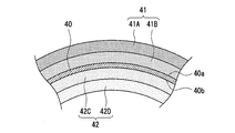
- FIG. 2 is a view showing a cross section of the negative electrode 12.
- the negative electrode 12 includes a negative electrode current collector 40 and a negative electrode mixture layer 41 (first electrode) formed on the first surface 40 a of the negative electrode current collector 40 facing the outside of the electrode body 14. 1 negative electrode composite material layer) and a negative electrode composite material layer 42 (second negative electrode composite material layer) formed on the second surface 40 b of the negative electrode current collector 40 facing the inside of the electrode body 14.
- the positive electrode 11 has a layer structure in which the positive electrode mixture layer 31 having a uniform composition is formed on both surfaces of the positive electrode current collector 30, but in the negative electrode 12, at least one of the negative electrode mixture layers 41 and 42 has Si And the content rate of the Si type active material comprised by at least one of Si containing material is changing continuously or in steps. As will be described in detail later, the content ratio of the Si-based active material is different between at least one of the negative electrode mixture layers 41 and 42 on the surface side of the mixture layer and the negative electrode current collector 40 side.
- the negative electrode current collector 40 a metal foil that is stable in the potential range of the negative electrode 12, such as copper or a copper alloy, a film in which the metal is disposed on the surface layer, or the like can be used.
- the negative electrode mixture layer 41 includes a negative electrode active material and a binder.
- the negative electrode 12 is formed by, for example, applying a negative electrode mixture slurry containing a negative electrode active material and a binder on the negative electrode current collector 40, drying the coating film, and compressing the negative electrode mixture layer 41.
- the negative electrode composite material layer 42 can be formed on the second surface 40 b of the negative electrode current collector 40 on the first surface 40 a of the body 40. As will be described in detail later, for example, four types of negative electrode mixture slurries with different Si-based active material content ratios are used to manufacture the negative electrode 12.
- the negative electrode 12 constituting the wound electrode body 14 is curved over the entire length in the longitudinal direction.
- the negative electrode 12 is manufactured in a flat plate state, and is bent by being wound together with the positive electrode 11 and the separator 13 when the electrode body 14 is manufactured.
- the negative electrode 12 generally has a radius of curvature of about 1 mm to 10 mm, and the radius of curvature differs between the winding start side and the winding end side of the electrode body 14.
- the radius of curvature of the negative electrode 12 is the winding start side end portion ⁇ the winding end side end portion.
- the minimum value of the radius of curvature of the negative electrode 12 is, for example, 1 mm to 5 mm, or 1 mm to 2 mm.
- the convex surface side is elongated and the concave surface side is compressed.
- the negative electrode mixture layer 41 formed on the first surface 40a of the negative electrode current collector 40 facing the outside of the electrode body 14 is expanded and formed on the second surface 40b of the negative electrode current collector 40 facing the inner side of the electrode body 14.
- the formed negative electrode mixture layer 42 is compressed.
- the thickness direction of the negative electrode composite material layer 41 the surface side of the composite material layer is expanded, and the negative electrode current collector 40 side is compressed.
- the negative electrode current collector 40 side is expanded, and the surface side of the mixture layer is compressed.
- the inventors have succeeded in improving the cycle characteristics of the battery by focusing on this point and improving the layer structure of the negative electrode 12.
- One of the negative electrode mixture layers 41 and 42 may not contain the Si-based active material.
- the Si-based active material is included in both the negative electrode mixture layers 41 and 42. Is preferred.
- the Si-based average content ratio of the Si-based active material in the negative electrode mixture layer 42 is preferably lower than the Si-based average content ratio of the Si-based active material in the negative electrode mixture layer 41.
- the spatial margin for allowing a large volume change of the Si-based active material is less than that of the negative electrode mixture layer 41.
- the Si-based content ratio of the Si-based active material in the negative electrode mixture layer 41 is preferably greater than the Si-based content ratio of the Si-based active material in the negative electrode mixture layer 42.
- the Si-based content ratio of the Si-based active material is calculated as a ratio of the Si-based mass of the Si-based active material to the mass of the negative electrode active material in each of the negative electrode mixture layers 41 and 42.
- the Si-based mass of the Si-based active material is calculated by multiplying the mass of the Si-based active material by the mass ratio of Si with respect to the Si-based active material.
- each negative electrode mixture layer 41, 42 is divided at equal intervals in the thickness direction.
- the surface side of each of the negative electrode mixture layers 41 and 42 and the current collector are calculated by calculating the content ratio of the Si-based Si-based active material in each layer. The content ratio of the Si-based active material based on Si on the body side can be compared.
- the Si-based content ratio of the Si-based active material in the negative electrode mixture layer 41 is set higher than the Si-based content ratio of the Si-based active material in the negative electrode mixture layer 42.
- the negative electrode mixture layer 41 since the negative electrode mixture layer 41 is stretched, the negative electrode mixture layer 41 has a spatial margin that allows a large volume change of the Si-based active material as compared with the negative electrode mixture layer 42. Even if the amount of the system active material is increased, the cycle characteristics are unlikely to deteriorate. *
- the Si-based content ratio of the Si-based active material is lower on the negative electrode current collector 40 side in the thickness direction of the negative electrode mixture layer 41 than on the surface side of the mixture layer.
- the Si-based content ratio of the Si-based active material is lower on the surface side of the mixture layer than on the negative electrode current collector 40 side.
- the negative electrode composite material layer 41 is divided in half at the center in the thickness direction, it is located closer to the negative electrode current collector 40 than a portion located on the surface side of the composite material layer away from the negative electrode current collector 40.
- the Si-based content of the Si-based active material is low.
- the Si-based active material Si is formed at a portion located on the surface side of the mixture layer rather than a portion located on the negative electrode current collector 40 side.
- the standard content is low.
- the negative electrode mixture layers 41 and 42 each have a multilayer structure.
- the negative electrode composite material layer 41 is disposed on the negative electrode current collector 40 side of the first layer 41A and the first layer 41A disposed on the surface side of the composite material layer, and the Si-based active material Si content ratio Includes a second layer 41B lower than the first layer 41A.
- the negative electrode composite material layer 42 is disposed on the surface side of the composite material layer with respect to the third layer 42C disposed on the negative electrode current collector 40 side and the third layer 42C, and the Si-based content ratio of the Si-based active material Includes a fourth layer 42D lower than the third layer 42C.
- the Si-based content ratio of the Si-based active material is from the outer peripheral side of the negative electrode 12 toward the inner peripheral side, that is, from the first layer 41A of the negative electrode mixture layer 41 to the fourth layer 42D side of the negative electrode mixture layer 42. And lower. That is, the Si-based content ratio of the Si-based active material is maximized in the first layer 41A and minimized in the fourth layer 42D.
- the Si-based content ratio of the Si-based active material in the second layer 41B and the Si-based content ratio of the Si-based active material in the third layer 42C may be the same, and the second layer 41B and the third layer The layer configuration of 42C may be the same.
- the Si-based content ratio of the Si-based active material may be set as the second layer 41B ⁇ the third layer 42C.
- the Si-based content ratio of the Si-based active material in the second layer 41B is preferably lower than the Si-based content ratio of the Si-based active material in the third layer 42C.
- the Si-based content ratio of the Si-based active material is such that the first layer 41A> the second layer 41B ⁇ the third layer 42C> the fourth layer 42D. preferable.
- the negative electrode mixture layers 41 and 42 are each composed of two layers having different Si-based content ratios of the Si-based active material, but may be composed of three or more layers.
- Each layer constituting the negative electrode mixture layers 41 and 42 preferably further contains a carbon-based active material. That is, it is preferable that a Si-based active material and a carbon-based active material are used in combination as the negative electrode active material. Considering cycle characteristics, the content of the Si-based active material in the negative electrode mixture layers 41 and 42 is preferably smaller than the content of the carbon-based active material.
- Suitable carbon-based active materials are natural graphite such as flaky graphite, massive graphite and earthy graphite, and graphite such as artificial graphite such as massive artificial graphite (MAG) and graphitized mesophase carbon microbeads (MCMB).
- the Si-based active material is composed of at least one of Si and a Si-containing material, but is preferably composed of a Si-containing material whose volume change during charge / discharge is smaller than that of Si.
- An example of the Si-containing material is a material represented by SiO x (0.5 ⁇ x ⁇ 1.6).
- SiO x has a structure in which, for example, Si fine particles are dispersed in a SiO 2 matrix.
- the Si-containing material may be a material (LSi) in which fine particles of Si are dispersed in a lithium silicate (Li 2y SiO (2 + y) (0 ⁇ y ⁇ 2)) phase.
- the negative electrode mixture layers 41 and 42 may contain SiO x and LSi.
- a conductive coating composed of a material having higher conductivity than the Si-containing material is formed on the particle surface of the Si-containing material.
- the constituent material of the conductive film include at least one selected from a carbon material, a metal, and a metal compound. Among these, a carbon material such as amorphous carbon is preferable.
- the carbon coating can be formed by, for example, a CVD method using acetylene, methane, or the like, a method in which coal pitch, petroleum pitch, phenol resin, or the like is mixed with Si-containing material particles and heat treatment is performed.
- the conductive coating may be formed by fixing a conductive filler such as carbon black to the particle surface of the Si-containing material using a binder.
- the conductive film is formed, for example, at 0.5 to 10% by mass with respect to the mass of the Si-containing material particles.
- the average content ratio of the Si-based active material in the negative electrode mixture layers 41 and 42 based on the Si is negative electrode mixture layer 41> negative electrode mixture layer 42.
- the difference in Si-based content ratio of the Si-based active material in the negative electrode mixture layers 41 and 42 is preferably 1.5% or more, more preferably 2% or more, and further preferably 2.5% or more.
- the difference in the content ratio of the Si-based active material in the first layer 41A and the second layer 41B and the difference in the content ratio of the Si-based active material in the third layer 42C and the fourth layer 42D are each preferably 1% or more. 1.5% or more is more preferable, and 2% or more is more preferable. In this case, the cycle specific improvement effect becomes more remarkable.
- the Si-based content ratio of the Si-based active material can be measured by ICP (Inductively Coupled Plasma: plasma emission analysis).
- the mass-based content ratio of the Si-based active material is also the negative electrode mixture layer 41> the negative electrode mixture layer 42.
- the first layer 41A> the second layer 41B ⁇ the third layer 42C> the fourth layer 42D is preferable.
- the average content ratio of the Si-based active material in the negative electrode mixture layer 41 is preferably 5% by mass to 25% by mass, and more preferably 10% by mass to 15% by mass.
- the average content ratio of the Si-based active material in the negative electrode mixture layer 42 is lower than the content ratio of the negative electrode mixture layer 41, and is preferably less than 15% by mass, more preferably 5% by mass to 10% by mass. is there.
- the content ratio of the Si-based active material in the negative electrode active material layer 41 is preferably 5% by mass to 25% by mass, and more preferably 10% by mass to 15% by mass.
- the content ratio of the Si-based active material in the negative electrode active material is preferably less than 15% by mass, and more preferably 5% by mass to 10% by mass.
- the content ratio of the carbon-based active material in the negative electrode active material layer 41 is preferably 75% by mass to 95% by mass, and the content ratio of the carbon-based active material in the negative electrode active material layer 42 in the negative electrode active material. Is preferably 85% by mass or more.
- a fluorine resin, PAN, polyimide, acrylic resin, polyolefin, or the like may be used as the binder contained in the negative electrode mixture layers 41 and 42, but styrene-butadiene rubber ( SBR) or a modified product thereof is used.
- SBR styrene-butadiene rubber
- the negative electrode mixture layers 41 and 42 may contain, for example, CMC or a salt thereof, polyacrylic acid (PAA) or a salt thereof, polyvinyl alcohol, or the like in addition to SBR or the like.
- the type and content of the binder in each layer constituting the negative electrode mixture layers 41 and 42 may be different from each other or the same.
- the negative electrode mixture layers 41 and 42 may have different thicknesses, but are preferably formed with substantially the same thickness.
- the thickness of the negative electrode mixture layers 41 and 42 is, for example, 30 ⁇ m to 80 ⁇ m, and preferably 40 ⁇ m to 60 ⁇ m.
- the layers constituting the negative electrode mixture layers 41 and 42 may have different thicknesses or may be formed with the same thickness.
- a negative electrode active material other than the Si-based active material and the carbon-based active material may be further added to the negative electrode mixture layers 41 and 42. Examples of the other negative electrode active material include metals that form an alloy with lithium other than Si, compounds containing the metal, and lithium titanate.
- the negative electrode mixture layer 41 including the first layer 41A and the second layer 41B on one surface of the negative electrode current collector 40, and the negative electrode composite including the third layer 42C and the fourth layer 42D on the other surface. Since the material layers 42 are formed, four types of negative electrode mixture slurries with different Si-based active material content ratios are used. For example, when forming the negative electrode mixture layer 41, the first negative electrode mixture slurry for the first layer 41A is applied on the negative electrode current collector 40, and then superimposed on the first negative electrode mixture slurry for the second layer 41B. 2 Apply negative electrode mixture slurry. At this time, the coating film of the first negative electrode mixture slurry may be in an undried state or in a dry state.
- the separator 13 a porous sheet having ion permeability and insulating properties is used. Specific examples of the porous sheet include a microporous thin film, a woven fabric, and a nonwoven fabric.
- an olefin resin such as polyethylene or polypropylene, cellulose, or the like is preferable.
- the separator 13 may have either a single layer structure or a laminated structure. A heat resistant layer or the like may be formed on the surface of the separator 13.
- Example 1 [Production of positive electrode] A lithium-containing metal composite oxide represented by LiNi 0.88 Co 0.09 Al 0.03 O 2 , carbon black, and polyvinylidene fluoride are mixed at a mass ratio of 100: 0.8: 0.7. After adding an appropriate amount of N-methyl-2-pyrrolidone, this was kneaded to prepare a positive electrode mixture slurry. The positive electrode mixture slurry is applied to both surfaces of a positive electrode current collector made of an aluminum foil having a thickness of 15 ⁇ m, and after the coating film is dried, the coating film is rolled using a roller and cut into a predetermined electrode size. A positive electrode having a positive electrode mixture layer formed on both sides of the positive electrode current collector was produced.
- a positive electrode current collector made of an aluminum foil having a thickness of 15 ⁇ m
- first negative electrode mixture slurry (first layer slurry)
- a negative electrode active material, a sodium salt of CMC, and polyacrylic acid were mixed at a mass ratio of 100: 1: 1, and then pure water was added so that the solid content was 60% by mass, followed by kneading for 30 minutes. . Thereafter, pure water was added so that the solid content was 50% by mass, and a dispersion of SBR was added so as to be 1% by mass with respect to the negative electrode active material to prepare a first negative electrode mixture slurry.
- Second negative electrode mixture slurry (second layer slurry)
- a second negative electrode mixture slurry was prepared in the same manner as in the case of the first negative electrode mixture slurry, except that the graphite powder and the Si-containing material were mixed at a mass ratio of 88.5: 11.5.
- third negative electrode mixture slurry (third layer slurry)
- a third negative electrode mixture slurry was prepared in the same manner as the first negative electrode mixture slurry, except that the graphite powder and the Si-containing material were mixed at a mass ratio of 90.5: 9.5.
- a fourth negative electrode mixture slurry was prepared in the same manner as the first negative electrode mixture slurry, except that the graphite powder and the Si-containing material were mixed at a mass ratio of 92.5: 7.5.
- the second negative electrode mixture slurry was applied to one surface of a negative electrode current collector made of a copper foil having a thickness of 8 ⁇ m, and then the first negative electrode mixture slurry was applied thereon. Similarly, the third negative electrode mixture slurry was applied to the other surface of the negative electrode current collector, and then the fourth negative electrode mixture slurry was applied thereon. At this time, the application amount of each slurry was the same. Next, after drying a coating film and rolling it using a roller, it is cut into a predetermined electrode size, and a negative electrode having a first negative electrode mixture layer having a two-layer structure and a second negative electrode mixture layer having a two-layer structure was made.
- a wound electrode body described later is manufactured so that one surface of the current collector is a first surface facing the outside of the electrode body and the other surface is a second surface facing the inside of the electrode body.
- Table 1 the content rate of Si containing material with respect to the gross mass of the negative electrode active material in each layer which comprises a negative electrode compound-material layer is shown.
- standard of the Si-containing material in each layer is shown in parentheses in Table 1.
- the positive electrode and the negative electrode are wound around a winding core having a radius of curvature of 1.5 mm through a separator made of polyethylene microporous film with a thickness of 20 ⁇ m, a tape is attached to the outermost peripheral surface, and a cylindrical winding A mold electrode body was produced.
- the positive electrode lead made of aluminum was welded to the exposed portion of the current collector of the positive electrode, and the negative electrode lead made of nickel was welded to the exposed portion of the current collector of the negative electrode.
- the electrode body was housed in a bottomed cylindrical outer can, the positive electrode lead was welded to the sealing body, and the negative electrode lead was welded to the inner bottom surface of the outer can.
- the opening of the outer can was sealed with a sealing body to produce a non-aqueous electrolyte secondary battery (height 65 mm, diameter 18 mm, design capacity 3500 mAh).
- Example 2 A negative electrode and a nonaqueous electrolyte secondary battery were produced in the same manner as in Example 1 except that the content ratio of the Si-containing material relative to the total mass of the negative electrode active material in each layer was changed to the amount shown in Table 1, and cycle characteristics were produced. Was evaluated.
- each layer of the first and second negative electrode mixture layers was formed using a negative electrode mixture slurry prepared by mixing graphite and a Si-containing material in a mass ratio of 89.5: 10.5.
- a negative electrode and a nonaqueous electrolyte secondary battery were produced, and the cycle characteristics were evaluated.
- Example 2 A negative electrode and a nonaqueous electrolyte secondary battery were produced in the same manner as in Example 1 except that the content ratio of the Si-containing material relative to the total mass of the negative electrode active material in each layer was changed to the amount shown in Table 1, and cycle characteristics were produced. Was evaluated.
- Example 3 A negative electrode and a nonaqueous electrolyte secondary battery were produced in the same manner as in Example 1 except that the content ratio of the Si-containing material relative to the total mass of the negative electrode active material in each layer was changed to the amount shown in Table 1, and cycle characteristics were produced. Was evaluated.
Landscapes
- Chemical & Material Sciences (AREA)
- Chemical Kinetics & Catalysis (AREA)
- Electrochemistry (AREA)
- General Chemical & Material Sciences (AREA)
- Engineering & Computer Science (AREA)
- Manufacturing & Machinery (AREA)
- Inorganic Chemistry (AREA)
- Composite Materials (AREA)
- Materials Engineering (AREA)
- Battery Electrode And Active Subsutance (AREA)
- Secondary Cells (AREA)
Abstract
本開示の目的は、負極活物質にSi系活物質を用いた巻回型の電極体を備える非水電解質二次電池において、サイクル特性を向上させることである。実施形態の一例である非水電解質二次電池において、負極は、負極集電体と、電極体の外側に向く負極集電体の第1面に形成された第1負極合材層と、電極体の内側に向く負極集電体の第2面に形成された第2負極合材層とを有する。第1負極合材層は、Si系活物質を含む。Si系活物質のSi基準の含有割合は、第1負極合材層の厚み方向において、当該合材層の表面側よりも負極集電体側で低い。
Description
本開示は、非水電解質二次電池に関し、より詳しくは巻回型の電極体を備えた非水電解質二次電池に関する。
Si及びSi含有材料は、黒鉛などの炭素材料と比べて単位体積当りに多くのリチウムイオンを吸蔵できることが知られている。このため、負極活物質にSi含有材料等を用いることで、電池の高容量化を図ることができる。例えば、特許文献1には、負極活物質に黒鉛及びSi含有材料を用いた非水電解質二次電池が開示されている。また、特許文献1には、負極合材層におけるSi含有材料に対する黒鉛の質量比(黒鉛の質量/Si含有材料の質量)が、負極集電体の表面から離れるに従って連続的又は断続的に大きくなった構成が開示されている。
ところで、Si及びSi含有材料は充放電に伴う体積変化が大きいため、負極活物質としてSi及びSi含有材料の少なくとも一方で構成されるSi系活物質を用いた非水電解質二次電池では、サイクル特性が低下し易いという課題がある。特に、巻回型の電極体を備える場合、巻き始め側端部などの負極の曲率半径が小さい部分においてSi系活物質の体積変化の影響が大きい。本開示の目的は、負極活物質としてSi系活物質を用いた巻回型の電極体を備える非水電解質二次電池において、サイクル特性を改善することである。
本開示に係る非水電解質二次電池は、正極と負極がセパレータを介して巻回された巻回型の電極体を備える非水電解質二次電池であって、前記負極は、負極集電体と、前記電極体の外側に向く前記負極集電体の第1面に形成された第1負極合材層と、前記電極体の内側に向く前記負極集電体の第2面に形成された第2負極合材層とを有する。第1負極合材層は、Si及びSi含有材料の少なくとも一方で構成されるSi系活物質を含み、Si系活物質のSi基準の含有割合は、前記第1負極合材層の厚み方向において、当該合材層の表面側よりも前記負極集電体側で低い。或いは、前記第2負極合材層は、Si及びSi含有材料の少なくとも一方で構成されるSi系活物質を含み、前記Si系活物質のSi基準の含有割合は、前記第2負極合材層の厚み方向において、前記負極集電体側よりも当該合材層の表面側で低い。
本開示の一態様によれば、負極活物質にSi系活物質を用いた巻回型の電極体を備える非水電解質二次電池において、サイクル特性を向上させることができる。
上述の通り、負極活物質としてSi系活物質を用いた巻回型の電極体を備える非水電解質二次電池では、サイクル特性が低下し易いという課題がある。かかるサイクル特性の低下は、充放電時におけるSi系活物質の大きな体積変化に起因して発生する。具体的には、Si系活物質の大きな体積変化によって活物質粒子同士の接触の程度が弱くなる、又は接触状態が失われて、負極合材層中の導電パスから孤立する活物質粒子が増えることが主な要因であると考えられる。巻回型の電極体では、特に巻き始め側端部などの負極の曲率半径が小さい部分において、Si系活物質の体積変化の影響が大きい。
本発明者らは、上述の課題を解決するために鋭意検討した結果、上記第1負極合材層及び第2負極合材層の少なくとも一方において、Si系活物質のSi基準の含有割合を改良することで、電池のサイクル特性が特異的に改善されることを見出した。本開示に係る非水電解質二次電池によれば、負極合材層にSi系活物質を効率良く添加して高容量化を図りつつ、サイクル特性の低下を抑制できる。
以下、本開示の実施形態の一例について詳細に説明する。以下では、巻回型の電極体14が円筒形状の電池ケース15に収容された円筒形電池を例示するが、電池ケースは円筒形に限定されず、例えば角形であってもよく、金属層及び樹脂層を含むラミネートシートで構成された電池ケースであってもよい。電極体は巻回構造を有していればよく、扁平状に成形されていてもよいが、本開示に係る負極の構成は電極体が円筒状の巻回構造を有する場合に特に効果的である。
図1は、実施形態の一例である非水電解質二次電池10の断面図である。図1に例示するように、非水電解質二次電池10は、巻回型の電極体14と、非水電解質(図示せず)と、電極体14及び非水電解質を収容する電池ケース15とを備える。電極体14は、正極11と負極12がセパレータ13を介して巻回されてなる巻回構造を有する。電池ケース15は、有底筒状の外装缶16と、外装缶16の開口部を塞ぐ封口体17とで構成される。また、非水電解質二次電池10は、外装缶16と封口体17との間に配置される樹脂製のガスケット28を備える。
非水電解質は、非水溶媒と、非水溶媒に溶解した電解質塩とを含む。非水溶媒には、例えばエステル類、エーテル類、ニトリル類、アミド類、及びこれらの2種以上の混合溶媒等を用いてもよい。非水溶媒は、これら溶媒の水素の少なくとも一部をフッ素等のハロゲン原子で置換したハロゲン置換体を含有していてもよい。なお、非水電解質は液体電解質に限定されず、ゲル状ポリマー等を用いた固体電解質であってもよい。電解質塩には、例えばLiPF6等のリチウム塩が使用される。
電極体14は、長尺状の正極11と、長尺状の負極12と、長尺状の2枚のセパレータ13と、正極11に接合された正極タブ20と、負極12に接合された負極タブ21とで構成される。負極12は、リチウムの析出を防止するために、正極11よりも一回り大きな寸法で形成される。即ち、負極12は、正極11より長手方向及び幅方向(短手方向)に長く形成される。2枚のセパレータ13は、少なくとも正極11よりも一回り大きな寸法で形成され、例えば正極11を挟むように配置される。
電極体14の上下には、絶縁板18,19がそれぞれ配置される。図1に示す例では、正極11に取り付けられた正極タブ20が絶縁板18の貫通孔を通って封口体17側に延び、負極12に取り付けられた負極タブ21が絶縁板19の外側を通って外装缶16の底部側に延びている。正極タブ20は封口体17の底板23の下面に溶接等で接続され、底板23と電気的に接続された封口体17の天板であるキャップ27が正極端子となる。負極タブ21は外装缶16の底部内面に溶接等で接続され、外装缶16が負極端子となる。
外装缶16は、例えば有底円筒形状の金属製容器である。上述のように、外装缶16と封口体17との間にはガスケット28が設けられ、電池ケース15の内部空間が密閉される。外装缶16は、例えば側面部を外側からプレスして形成された、封口体17を支持する溝入れ部22を有する。溝入れ部22は、外装缶16の周方向に沿って環状に形成されることが好ましく、その上面で封口体17を支持する。また、外装缶16の上端部は、内側に折り曲げられ封口体17の周縁部に加締められている。
封口体17は、電極体14側から順に、底板23、下弁体24、絶縁部材25、上弁体26、及びキャップ27が積層された構造を有する。封口体17を構成する各部材は、例えば円板形状又はリング形状を有し、絶縁部材25を除く各部材は互いに電気的に接続されている。下弁体24と上弁体26は各々の中央部で接続され、各々の周縁部の間には絶縁部材25が介在している。異常発熱で電池の内圧が上昇すると、下弁体24が上弁体26をキャップ27側に押し上げるように変形して破断することにより、下弁体24と上弁体26の間の電流経路が遮断される。さらに内圧が上昇すると、上弁体26が破断し、キャップ27の開口部からガスが排出される。
[正極]
正極11は、正極集電体30と、正極集電体30の両面に形成された正極合材層31とを有する。正極集電体30には、アルミニウム、アルミニウム合金など、正極11の電位範囲で安定な金属の箔、当該金属を表層に配置したフィルム等を用いることができる。正極合材層31は、正極活物質、導電材、及び結着材を含む。正極11は、例えば正極集電体30上に正極活物質、導電材、及び結着材等を含む正極合材スラリーを塗布し、塗膜を乾燥させた後、圧縮して正極合材層31を正極集電体30の両面に形成することにより作製できる。
正極11は、正極集電体30と、正極集電体30の両面に形成された正極合材層31とを有する。正極集電体30には、アルミニウム、アルミニウム合金など、正極11の電位範囲で安定な金属の箔、当該金属を表層に配置したフィルム等を用いることができる。正極合材層31は、正極活物質、導電材、及び結着材を含む。正極11は、例えば正極集電体30上に正極活物質、導電材、及び結着材等を含む正極合材スラリーを塗布し、塗膜を乾燥させた後、圧縮して正極合材層31を正極集電体30の両面に形成することにより作製できる。
正極活物質は、リチウム含有金属複合酸化物を主成分として構成される。リチウム含有金属複合酸化物に含有される金属元素としては、Ni、Co、Mn、Al、B、Mg、Ti、V、Cr、Fe、Cu、Zn、Ga、Sr、Zr、Nb、In、Sn、Ta、W等が挙げられる。好適なリチウム含有金属複合酸化物の一例は、Ni、Co、Mn、Alの少なくとも1種を含有する複合酸化物である。なお、リチウム含有金属複合酸化物の粒子表面には、酸化アルミニウム、ランタノイド含有化合物等の無機化合物粒子などが固着していてもよい。
正極合材層31に含まれる導電材としては、カーボンブラック、アセチレンブラック、ケッチェンブラック、黒鉛等の炭素材料が例示できる。正極合材層31に含まれる結着材としては、ポリテトラフルオロエチレン(PTFE)、ポリフッ化ビニリデン(PVdF)等のフッ素樹脂、ポリアクリロニトリル(PAN)、ポリイミド、アクリル樹脂、ポリオレフィンなどが例示できる。これらの樹脂と、カルボキシメチルセルロース(CMC)又はその塩等のセルロース誘導体、ポリエチレンオキシド(PEO)などが併用されてもよい。
[負極]
図2は、負極12の断面を示す図である。図1及び図2に例示するように、負極12は、負極集電体40と、電極体14の外側に向く負極集電体40の第1面40aに形成された負極合材層41(第1負極合材層)と、電極体14の内側に向く負極集電体40の第2面40bに形成された負極合材層42(第2負極合材層)とを有する。正極11は正極集電体30の両面に合材の組成が均一な正極合材層31が形成された層構造を有するが、負極12では、負極合材層41,42の少なくとも一方において、Si及びSi含有材料の少なくとも一方で構成されるSi系活物質の含有割合が連続的又は段階的に変化している。詳しくは後述するが、負極合材層41,42の少なくとも一方では、合材層の表面側と負極集電体40側とでSi系活物質の含有割合が異なっている。
図2は、負極12の断面を示す図である。図1及び図2に例示するように、負極12は、負極集電体40と、電極体14の外側に向く負極集電体40の第1面40aに形成された負極合材層41(第1負極合材層)と、電極体14の内側に向く負極集電体40の第2面40bに形成された負極合材層42(第2負極合材層)とを有する。正極11は正極集電体30の両面に合材の組成が均一な正極合材層31が形成された層構造を有するが、負極12では、負極合材層41,42の少なくとも一方において、Si及びSi含有材料の少なくとも一方で構成されるSi系活物質の含有割合が連続的又は段階的に変化している。詳しくは後述するが、負極合材層41,42の少なくとも一方では、合材層の表面側と負極集電体40側とでSi系活物質の含有割合が異なっている。
負極集電体40には、銅、銅合金など、負極12の電位範囲で安定な金属の箔、当該金属を表層に配置したフィルム等を用いることができる。負極合材層41は、負極活物質及び結着材を含む。負極12は、例えば負極集電体40上に負極活物質及び結着材等を含む負極合材スラリーを塗布し、塗膜を乾燥させた後、圧縮して負極合材層41を負極集電体40の第1面40aに、負極合材層42を負極集電体40の第2面40bに形成することにより作製できる。詳しくは後述するが、負極12の製造には、例えばSi系活物質の含有割合が異なる4種類の負極合材スラリーが使用される。
図2に例示するように、巻回型の電極体14を構成する負極12は、長手方向の全長にわたって湾曲している。負極12は、平板の状態で製造され、電極体14の製造時に正極11及びセパレータ13と共に巻回されることで湾曲する。負極12は、一般的に1mm~10mm程度の曲率半径を有し、電極体14の巻き始め側と巻き終わり側では曲率半径が異なる。負極12の曲率半径は、巻き始め側端部<巻き終わり側端部となる。負極12の曲率半径の最小値は、例えば1mm~5mm、又は1mm~2mmである。
負極12は、平板の状態で製造されるため、湾曲した状態では凸面側が伸長され、凹面側が圧縮される。つまり、電極体14の外側に向く負極集電体40の第1面40aに形成された負極合材層41は伸長され、電極体14の内側に向く負極集電体40の第2面40bに形成された負極合材層42は圧縮される。さらに、負極合材層41の厚み方向において、当該合材層の表面側は伸長され、負極集電体40側は圧縮される。他方、負極合材層42の厚み方向において、負極集電体40側は伸長され、当該合材層の表面側は圧縮される。本発明者らは、この点に着目して負極12の層構造を改良することで、電池のサイクル特性を向上させることに成功した。
負極合材層41,42の一方はSi系活物質を含んでいなくてもよいが、高容量化等の観点から、Si系活物質は負極合材層41,42の両方に含まれることが好ましい。この場合、負極合材層42におけるSi系活物質のSi基準の平均含有割合は、負極合材層41におけるSi系活物質のSi基準の平均含有割合よりも低いことが好ましい。上述のように、負極合材層42は圧縮されるので、負極合材層41と比較してSi系活物質の大きな体積変化を許容する空間的余裕が少ない。このため、サイクル特性向上の観点から、負極合材層41におけるSi系活物質のSi基準の含有割合>負極合材層42におけるSi系活物質のSi基準の含有割合とすることが好ましい。Si系活物質のSi基準の含有割合は、各負極合材層41,42における負極活物質の質量に対するSi系活物質のSi基準の質量の割合として算出される。Si系活物質のSi基準の質量は、Si系活物質の質量にSi系活物質に対するSiの質量比率を乗じて算出される。各負極合材層41,42の表面側と集電体側のSi基準のSi系活物質の含有割合を比較する方法として、例えば、各負極合材層41,42を厚み方向に等間隔に分割し、それぞれのSi基準のSi系活物質の含有割合を算出して比較する方法が挙げられる。各負極合材層41,42が複層構造を有する場合は、それぞれの層のSi基準のSi系活物質の含有割合を算出することにより各負極合材層41,42の表面側と集電体側のSi基準のSi系活物質の含有割合を比較することができる。
言い換えると、負極合材層41におけるSi系活物質のSi基準の含有割合を、負極合材層42におけるSi系活物質のSi基準の含有割合よりも高くする。上述のように、負極合材層41は伸長されるので、負極合材層41は負極合材層42と比較してSi系活物質の大きな体積変化を許容する空間的余裕があるため、Si系活物質の量を多くしてもサイクル特性の低下につながり難い。
Si系活物質のSi基準の含有割合は、負極合材層41の厚み方向において、当該合材層の表面側よりも負極集電体40側で低くなっている。他方、負極合材層42の厚み方向において、Si系活物質のSi基準の含有割合は、負極集電体40側よりも当該合材層の表面側で低くなっている。例えば、負極合材層41を厚み方向中央で半分に分けたときに、負極集電体40から離れた当該合材層の表面側に位置する部分よりも、負極集電体40側に位置する部分でSi系活物質のSi基準の含有割合が低くなっている。また、負極合材層42を厚み方向中央で半分に分けたときに、負極集電体40側に位置する部分よりも、当該合材層の表面側に位置する部分でSi系活物質のSi基準の含有割合が低くなっている。
本実施形態では、負極合材層41,42がそれぞれ複層構造を有する。負極合材層41は、当該合材層の表面側に配置される第1層41Aと、第1層41Aよりも負極集電体40側に配置され、Si系活物質のSi基準の含有割合が第1層41Aよりも低い第2層41Bとを含む。負極合材層42は、負極集電体40側に配置される第3層42Cと、第3層42Cよりも当該合材層の表面側に配置され、Si系活物質のSi基準の含有割合が第3層42Cよりも低い第4層42Dとを含む。
Si系活物質のSi基準の含有割合は、負極12の外周側から内周側に向かって、即ち負極合材層41の第1層41Aから負極合材層42の第4層42D側に向かって低くなることが好ましい。つまり、Si系活物質のSi基準の含有割合は、第1層41Aで最大となり、第4層42Dで最小となる。一方、第2層41BにおけるSi系活物質のSi基準の含有割合と、第3層42CにおけるSi系活物質のSi基準の含有割合は同じであってもよく、第2層41B及び第3層42Cの層構成は同じであってもよい。Si系活物質の平均Si基準の含有割合が負極合材層41>負極合材層42を満たす範囲で、Si系活物質のSi基準の含有割合を第2層41B<第3層42Cとしてもよいが、第2層41BにおけるSi系活物質のSi基準の含有割合は、第3層42CにおけるSi系活物質のSi基準の含有割合よりも低いことが好ましい。
つまり、負極合材層41,42を構成する各層において、Si系活物質のSi基準の含有割合は、第1層41A>第2層41B≧第3層42C>第4層42Dであることが好ましい。負極合材層41,42におけるSi系活物質のSi基準の含有割合をこのように制御することで、Si系活物質を効率良く添加して高容量化を図りつつ、サイクル特性の低下を抑制できる。なお、負極合材層41,42は、それぞれSi系活物質のSi基準の含有割合が異なる2つの層で構成されているが、3つ以上の層で構成されていてもよい。
負極合材層41,42を構成する各層は、さらに炭素系活物質を含むことが好ましい。即ち、負極活物質として、Si系活物質と炭素系活物質が併用されることが好ましい。サイクル特性を考慮すると、負極合材層41,42におけるSi系活物質の含有量は、炭素系活物質の含有量よりも少量であることが好ましい。好適な炭素系活物質は、鱗片状黒鉛、塊状黒鉛、土状黒鉛等の天然黒鉛、塊状人造黒鉛(MAG)、黒鉛化メソフェーズカーボンマイクロビーズ(MCMB)等の人造黒鉛などの黒鉛である。
Si系活物質は、Si及びSi含有材料の少なくとも一方で構成されるが、好ましくは充放電時の体積変化がSiよりも小さなSi含有材料で構成される。Si含有材料としては、SiOx(0.5≦x≦1.6)で表される材料が例示される。SiOxは、例えばのSiO2マトリックス中にSiの微粒子が分散した構造を有する。Si含有材料は、リチウムシリケート(Li2ySiO(2+y)(0<y<2))相中にSiの微粒子が分散した材料(LSi)であってもよい。負極合材層41,42には、SiOx及びLSiが含まれていてもよい。
Si含有材料の粒子表面には、Si含有材料よりも導電性の高い材料で構成される導電被膜が形成されていることが好ましい。導電被膜の構成材料としては、炭素材料、金属、及び金属化合物から選択される少なくとも1種が例示できる。中でも、非晶質炭素等の炭素材料が好ましい。炭素被膜は、例えばアセチレン、メタン等を用いたCVD法、石炭ピッチ、石油ピッチ、フェノール樹脂等をSi含有材料粒子と混合し、熱処理を行う方法などで形成できる。また、カーボンブラック等の導電フィラーを結着材を用いてSi含有材料の粒子表面に固着させることで導電被膜を形成してもよい。導電被膜は、例えばSi含有材料粒子の質量に対して0.5~10質量%で形成される。
負極合材層41,42におけるSi系活物質のSi基準の平均含有割合は、上述の通り、負極合材層41>負極合材層42である。負極合材層41,42におけるSi系活物質のSi基準の含有割合差は、1.5%以上が好ましく、2%以上がより好ましく、2.5%以上がさらに好ましい。また、第1層41Aと第2層41BのSi系活物質の含有割合の差、及び第3層42Cと第4層42DのSi系活物質の含有割合の差は、それぞれ1%以上が好ましく、1.5%以上がより好ましく、2%以上がさらに好ましい。この場合、サイクル特定の改善効果がより顕著になる。Si系活物質のSi基準の含有割合は、ICP(Inductively Coupled Plasma:プラズマ発光分析)により測定できる。
負極活物質として、Si系活物質と炭素系活物質が併用される場合、Si系活物質(Si含有材料)の質量基準の含有割合も、負極合材層41>負極合材層42であり、第1層41A>第2層41B≧第3層42C>第4層42Dであることが好ましい。負極合材層41におけるSi系活物質の平均含有割合は、5質量%~25質量%が好ましく、10質量%~15質量%がより好ましい。負極合材層42におけるSi系活物質の平均含有割合は、負極合材層41の当該含有割合より低い値であって、好ましくは15質量%未満、より好ましくは5質量%~10質量%である。なお、各層には、異なるSi系活物質を添加してもよい。
負極合材層41において負極活物質に占めるSi系活物質の含有割合は、5質量%~25質量%が好ましく、10質量%~15質量%がより好ましい。負極合材層42において負極活物質に占めるSi系活物質の含有割合は、15質量%未満が好ましく、5質量%~10質量%がより好ましい。換言すると、負極合材層41において負極活物質に占める炭素系活物質の含有割合は75質量%~95質量%が好ましく、負極合材層42において負極活物質に占める炭素系活物質の含有割合は85質量%以上が好ましい。
負極合材層41,42に含まれる結着材には、正極11の場合と同様に、フッ素樹脂、PAN、ポリイミド、アクリル樹脂、ポリオレフィン等を用いてもよいが、好ましくはスチレン-ブタジエンゴム(SBR)又はその変性体を用いる。負極合材層41,42には、例えばSBR等に加えて、CMC又はその塩、ポリアクリル酸(PAA)又はその塩、ポリビニルアルコールなどが含まれていてもよい。負極合材層41,42を構成する各層における結着材の種類及び含有量は、互いに異なっていてもよく、同じであってもよい。
負極合材層41,42は、互いに異なる厚みを有していてもよいが、好ましくは略同じ厚みで形成される。負極合材層41,42の厚みは、例えば30μm~80μmであり、好ましくは40μm~60μmである。負極合材層41,42を構成する各層についても、互いに異なる厚みを有していてもよく、同じ厚みで形成されていてもよい。負極合材層41,42には、Si系活物質及び炭素系活物質以外の他の負極活物質がさらに添加されてもよい。他の負極活物質としては、Si以外のリチウムと合金化する金属、当該金属を含有する化合物、チタン酸リチウムなどが例示できる。
本実施形態では、負極集電体40の一方の面に第1層41A及び第2層41Bを含む負極合材層41が、他方の面に第3層42C及び第4層42Dを含む負極合材層42が、それぞれ形成されるので、Si系活物質の含有割合が異なる4種類の負極合材スラリーが使用される。例えば、負極合材層41を形成する際には、第1層41A用の第1負極合材スラリーを負極集電体40上に塗布した後、その上に重ねて第2層41B用の第2負極合材スラリーを塗布する。この際、第1負極合材スラリーの塗膜は未乾燥状態であってもよく、乾燥状態であってもよい。
[セパレータ]
セパレータ13には、イオン透過性及び絶縁性を有する多孔性シートが用いられる。多孔性シートの具体例としては、微多孔薄膜、織布、不織布等が挙げられる。セパレータ13の材質としては、ポリエチレン、ポリプロピレン等のオレフィン樹脂、セルロースなどが好適である。セパレータ13は、単層構造、積層構造のいずれであってもよい。セパレータ13の表面には、耐熱層などが形成されていてもよい。
セパレータ13には、イオン透過性及び絶縁性を有する多孔性シートが用いられる。多孔性シートの具体例としては、微多孔薄膜、織布、不織布等が挙げられる。セパレータ13の材質としては、ポリエチレン、ポリプロピレン等のオレフィン樹脂、セルロースなどが好適である。セパレータ13は、単層構造、積層構造のいずれであってもよい。セパレータ13の表面には、耐熱層などが形成されていてもよい。
以下、実施例により本開示をさらに説明するが、本開示はこれらの実施例に限定されるものではない。
<実施例1>
[正極の作製]
LiNi0.88Co0.09Al0.03O2で表されるリチウム含有金属複合酸化物と、カーボンブラックと、ポリフッ化ビニリデンとを、100:0.8:0.7の質量比で混合し、N-メチル-2-ピロリドンを適量加えた後、これを混練して正極合材スラリーを調製した。当該正極合材スラリーを厚みが15μmのアルミニウム箔からなる正極集電体の両面に塗布し、塗膜を乾燥させた後、ローラーを用いて塗膜を圧延し、所定の電極サイズに切断して、正極集電体の両面に正極合材層が形成された正極を作製した。
[正極の作製]
LiNi0.88Co0.09Al0.03O2で表されるリチウム含有金属複合酸化物と、カーボンブラックと、ポリフッ化ビニリデンとを、100:0.8:0.7の質量比で混合し、N-メチル-2-ピロリドンを適量加えた後、これを混練して正極合材スラリーを調製した。当該正極合材スラリーを厚みが15μmのアルミニウム箔からなる正極集電体の両面に塗布し、塗膜を乾燥させた後、ローラーを用いて塗膜を圧延し、所定の電極サイズに切断して、正極集電体の両面に正極合材層が形成された正極を作製した。
[第1負極合材スラリー(第1層用スラリー)の調製]
黒鉛粉末と、炭素被膜を有するSiOx(x=1)で表されるSi含有材料とを、86.5:13.5の質量比で混合して、負極活物質を調製した。負極活物質と、CMCのナトリウム塩と、ポリアクリル酸とを、100:1:1の質量比で混合した後、固形分が60質量%となるように純水を加えて30分間混錬した。その後、固形分が50質量%となるように純水を追加し、負極活物質に対して1質量%となるようにSBRのディスパージョンを添加して、第1負極合材スラリーを調製した。
黒鉛粉末と、炭素被膜を有するSiOx(x=1)で表されるSi含有材料とを、86.5:13.5の質量比で混合して、負極活物質を調製した。負極活物質と、CMCのナトリウム塩と、ポリアクリル酸とを、100:1:1の質量比で混合した後、固形分が60質量%となるように純水を加えて30分間混錬した。その後、固形分が50質量%となるように純水を追加し、負極活物質に対して1質量%となるようにSBRのディスパージョンを添加して、第1負極合材スラリーを調製した。
[第2負極合材スラリー(第2層用スラリー)の調製]
黒鉛粉末と、Si含有材料とを、88.5:11.5の質量比で混合したこと以外は、第1負極合材スラリーの場合と同様にして、第2負極合材スラリーを調製した。
黒鉛粉末と、Si含有材料とを、88.5:11.5の質量比で混合したこと以外は、第1負極合材スラリーの場合と同様にして、第2負極合材スラリーを調製した。
[第3負極合材スラリー(第3層用スラリー)の調製]
黒鉛粉末と、Si含有材料とを、90.5:9.5の質量比で混合したこと以外は、第1負極合材スラリーの場合と同様にして、第3負極合材スラリーを調製した。
黒鉛粉末と、Si含有材料とを、90.5:9.5の質量比で混合したこと以外は、第1負極合材スラリーの場合と同様にして、第3負極合材スラリーを調製した。
[第4負極合材スラリー(第4層用スラリー)の調製]
黒鉛粉末と、Si含有材料とを、92.5:7.5の質量比で混合したこと以外は、第1負極合材スラリーの場合と同様にして、第4負極合材スラリーを調製した。
黒鉛粉末と、Si含有材料とを、92.5:7.5の質量比で混合したこと以外は、第1負極合材スラリーの場合と同様にして、第4負極合材スラリーを調製した。
[負極の作製]
上記第2負極合材スラリーを厚みが8μmの銅箔からなる負極集電体の一方の面に塗布した後、その上に重ねて上記第1負極合材スラリーを塗布した。同様に、負極集電体の他方の面に、上記第3負極合材スラリーを塗布した後、その上に重ねて上記第4負極合材スラリーを塗布した。このとき、各スラリーの塗布量は同じとした。次に、塗膜を乾燥させ、ローラーを用いて圧延した後、所定の電極サイズに切断して、2層構造の第1負極合材層及び2層構造の第2負極合材層を有する負極を作製した。なお、集電体の一方の面が電極体の外側に向く第1面、他方の面が電極体の内側に向く第2面になるように、後述の巻回型電極体を作製する。表1では、負極合材層を構成する各層における負極活物質の総質量に対するSi含有材料の含有割合を示す。また、表1のカッコ内に各層におけるSi含有材料のSi基準の含有割合を示す。
上記第2負極合材スラリーを厚みが8μmの銅箔からなる負極集電体の一方の面に塗布した後、その上に重ねて上記第1負極合材スラリーを塗布した。同様に、負極集電体の他方の面に、上記第3負極合材スラリーを塗布した後、その上に重ねて上記第4負極合材スラリーを塗布した。このとき、各スラリーの塗布量は同じとした。次に、塗膜を乾燥させ、ローラーを用いて圧延した後、所定の電極サイズに切断して、2層構造の第1負極合材層及び2層構造の第2負極合材層を有する負極を作製した。なお、集電体の一方の面が電極体の外側に向く第1面、他方の面が電極体の内側に向く第2面になるように、後述の巻回型電極体を作製する。表1では、負極合材層を構成する各層における負極活物質の総質量に対するSi含有材料の含有割合を示す。また、表1のカッコ内に各層におけるSi含有材料のSi基準の含有割合を示す。
[電極体の作製]
上記正極及び上記負極を、ポリエチレン製微多孔膜からなる厚みが20μmのセパレータを介して曲率半径1.5mmの巻き芯に巻回し、最外周面にテープを貼着して、円筒状の巻回型電極体を作製した。なお、正極の集電体露出部にアルミニウム製の正極リードを、負極の集電体露出部にニッケル製の負極リードをそれぞれ溶接した。
上記正極及び上記負極を、ポリエチレン製微多孔膜からなる厚みが20μmのセパレータを介して曲率半径1.5mmの巻き芯に巻回し、最外周面にテープを貼着して、円筒状の巻回型電極体を作製した。なお、正極の集電体露出部にアルミニウム製の正極リードを、負極の集電体露出部にニッケル製の負極リードをそれぞれ溶接した。
[非水電解質の調製]
エチレンカーボネートと、ジメチルカーボネートと、エチルメチルカーボネートとを、20:60:20の体積比で混合した混合溶媒に、ビニレンカーボネートを2質量%の濃度で溶解させた。その後、LiPF6を1.3モル/リットルの濃度になるように溶解させて、非水電解質を調製した。
エチレンカーボネートと、ジメチルカーボネートと、エチルメチルカーボネートとを、20:60:20の体積比で混合した混合溶媒に、ビニレンカーボネートを2質量%の濃度で溶解させた。その後、LiPF6を1.3モル/リットルの濃度になるように溶解させて、非水電解質を調製した。
[電池の作製]
上記電極体を有底円筒形状の外装缶内に収容し、正極リードを封口体に、負極リードを外装缶の内底面にそれぞれ溶接した。上記非水電解質を外装缶に注液した後、封口体で外装缶の開口を封止して、非水電解質二次電池(高さ65mm、直径18mm、設計容量3500mAh)を作製した。
上記電極体を有底円筒形状の外装缶内に収容し、正極リードを封口体に、負極リードを外装缶の内底面にそれぞれ溶接した。上記非水電解質を外装缶に注液した後、封口体で外装缶の開口を封止して、非水電解質二次電池(高さ65mm、直径18mm、設計容量3500mAh)を作製した。
[サイクル特性(容量維持率)の評価]
上記電池を、25℃の温度条件下、以下の条件で充放電して、容量維持率を求めた。表1に示す評価結果は、比較例1の電池の容量維持率を100としたときの相対値である。
<充放電条件>
充電:電流1050mAで電池電圧が4.2Vとなるまで定電流充電を行った。さらに、4.2Vの電圧で電流値が70mAとなるまで定電圧充電を行った。
放電:定電流1750mAで電圧が2.5Vとなるまで定電流放電を行った。
この充放電を100サイクル行い、下記式にて容量維持率を算出した。
容量維持率(%)100サイクル目放電容量÷1サイクル目放電容量×100
上記電池を、25℃の温度条件下、以下の条件で充放電して、容量維持率を求めた。表1に示す評価結果は、比較例1の電池の容量維持率を100としたときの相対値である。
<充放電条件>
充電:電流1050mAで電池電圧が4.2Vとなるまで定電流充電を行った。さらに、4.2Vの電圧で電流値が70mAとなるまで定電圧充電を行った。
放電:定電流1750mAで電圧が2.5Vとなるまで定電流放電を行った。
この充放電を100サイクル行い、下記式にて容量維持率を算出した。
容量維持率(%)100サイクル目放電容量÷1サイクル目放電容量×100
<実施例2>
各層における負極活物質の総質量に対するSi含有材料の含有割合を表1に示す量に変更したこと以外は、実施例1と同様にして、負極及び非水電解質二次電池を作製し、サイクル特性の評価を行った。
各層における負極活物質の総質量に対するSi含有材料の含有割合を表1に示す量に変更したこと以外は、実施例1と同様にして、負極及び非水電解質二次電池を作製し、サイクル特性の評価を行った。
<比較例1>
黒鉛と、Si含有材料とを、89.5:10.5の質量比で混合して調製した負極合材スラリーを用いて、第1及び第2負極合材層の各層を形成したこと以外は、実施例1と同様にして、負極及び非水電解質二次電池を作製し、サイクル特性の評価を行った。
黒鉛と、Si含有材料とを、89.5:10.5の質量比で混合して調製した負極合材スラリーを用いて、第1及び第2負極合材層の各層を形成したこと以外は、実施例1と同様にして、負極及び非水電解質二次電池を作製し、サイクル特性の評価を行った。
<比較例2>
各層における負極活物質の総質量に対するSi含有材料の含有割合を表1に示す量に変更したこと以外は、実施例1と同様にして、負極及び非水電解質二次電池を作製し、サイクル特性の評価を行った。
各層における負極活物質の総質量に対するSi含有材料の含有割合を表1に示す量に変更したこと以外は、実施例1と同様にして、負極及び非水電解質二次電池を作製し、サイクル特性の評価を行った。
<比較例3>
各層における負極活物質の総質量に対するSi含有材料の含有割合を表1に示す量に変更したこと以外は、実施例1と同様にして、負極及び非水電解質二次電池を作製し、サイクル特性の評価を行った。
各層における負極活物質の総質量に対するSi含有材料の含有割合を表1に示す量に変更したこと以外は、実施例1と同様にして、負極及び非水電解質二次電池を作製し、サイクル特性の評価を行った。

表1に示すように、Si系活物質のSi基準の含有割合を、第1層>第2層>第3層>第4層とした実施例の電池はいずれも、比較例の電池と比べて容量維持率が高く、サイクル特性に優れる。第1層と第2層、第2層と第3層、及び第3層と第4層におけるSi系活物質の含有割合の差が1%である実施例2の電池においても、サイクル特性の向上が顕著に確認された。なお、比較例2のように負極集電体側に向かってSi系活物質の含有割合を高くした場合、及び比較例3のように負極集電体と反対側に向かってSi系活物質の含有割合を高くした場合は、容量維持率が大きく低下することが分かった。
10 非水電解質二次電池、11 正極、12 負極、13 セパレータ、14 電極体、15 電池ケース、16 外装缶、17 封口体、18,19 絶縁板、20 正極タブ、21 負極タブ、22 溝入れ部、23 底板、24 下弁体、25 絶縁部材、26 上弁体、27 キャップ、28 ガスケット、30 正極集電体、31 正極合材層、40 負極集電体、40a 第1面、40b 第2面、41,42 負極合材層、41A 第1層、41B 第2層、42C 第3層、42D 第4層
Claims (8)
- 正極と負極がセパレータを介して巻回された巻回型の電極体を備える非水電解質二次電池であって、
前記負極は、負極集電体と、前記電極体の外側に向く前記負極集電体の第1面に形成された第1負極合材層と、前記電極体の内側に向く前記負極集電体の第2面に形成された第2負極合材層とを有し、
前記第1負極合材層は、Si及びSi含有材料の少なくとも一方で構成されるSi系活物質を含み、
前記Si系活物質のSi基準の含有割合は、前記第1負極合材層の厚み方向において、当該合材層の表面側よりも前記負極集電体側で低い、非水電解質二次電池。 - 正極と負極がセパレータを介して巻回された巻回型の電極体を備える非水電解質二次電池であって、
前記負極は、負極集電体と、前記電極体の外側に向く前記負極集電体の第1面に形成された第1負極合材層と、前記電極体の内側に向く前記負極集電体の第2面に形成された第2負極合材層とを有し、
前記第2負極合材層は、Si及びSi含有材料の少なくとも一方で構成されるSi系活物質を含み、
前記Si系活物質のSi基準の含有割合は、前記第2負極合材層の厚み方向において、前記負極集電体側よりも当該合材層の表面側で低い、非水電解質二次電池。 - 前記第2負極合材層は、前記Si系活物質を含み、
前記Si系活物質のSi基準の含有割合は、前記第2負極合材層の厚み方向において、前記負極集電体側よりも当該合材層の表面側で低い、請求項1に記載の非水電解質二次電池。 - 前記第2負極合材層における前記Si系活物質のSi基準の平均含有割合は、前記第1負極合材層における前記Si系活物質のSi基準の平均含有割合よりも低い、請求項1~3のいずれか1項に記載の非水電解質二次電池。
- 前記第1負極合材層は、当該合材層の表面側に配置される第1層と、前記第1層よりも前記負極集電体側に配置され、前記Si系活物質のSi基準の含有割合が前記第1層よりも低い第2層とを含み、
前記第2負極合材層は、前記負極集電体側に配置される第3層と、前記第3層よりも当該合材層の表面側に配置され、前記Si系活物質のSi基準の含有割合が前記第3層よりも低い第4層とを含む、請求項4に記載の非水電解質二次電池。 - 前記第1負極合材層における前記Si系活物質の含有割合は5重量%~25重量%であり、
前記第2負極合材層における前記Si系活物質の含有割合は15重量%未満である、請求項4又は5に記載の非水電解質二次電池。 - 前記負極の曲率半径の最小値は、1mm~5mmである、請求項1~6のいずれか1項に記載の非水電解質二次電池。
- 前記第1負極合材層及び前記第2負極合材層は、炭素系負極活物質を含む、請求項1~7のいずれか1項に記載の非水電解質二次電池。
Priority Applications (4)
| Application Number | Priority Date | Filing Date | Title |
|---|---|---|---|
| CN201980035918.0A CN112204768B (zh) | 2018-05-30 | 2019-04-26 | 非水电解质二次电池 |
| EP19811323.5A EP3813158A4 (en) | 2018-05-30 | 2019-04-26 | NON-AQUEOUS ELECTROLYTE SECONDARY BATTERY |
| JP2020521809A JP7386432B2 (ja) | 2018-05-30 | 2019-04-26 | 非水電解質二次電池 |
| US17/054,881 US12009512B2 (en) | 2018-05-30 | 2019-04-26 | Nonaqueous electrolyte secondary battery |
Applications Claiming Priority (2)
| Application Number | Priority Date | Filing Date | Title |
|---|---|---|---|
| JP2018103824 | 2018-05-30 | ||
| JP2018-103824 | 2018-05-30 |
Publications (1)
| Publication Number | Publication Date |
|---|---|
| WO2019230298A1 true WO2019230298A1 (ja) | 2019-12-05 |
Family
ID=68697511
Family Applications (1)
| Application Number | Title | Priority Date | Filing Date |
|---|---|---|---|
| PCT/JP2019/017893 WO2019230298A1 (ja) | 2018-05-30 | 2019-04-26 | 非水電解質二次電池 |
Country Status (5)
| Country | Link |
|---|---|
| US (1) | US12009512B2 (ja) |
| EP (1) | EP3813158A4 (ja) |
| JP (1) | JP7386432B2 (ja) |
| CN (1) | CN112204768B (ja) |
| WO (1) | WO2019230298A1 (ja) |
Cited By (3)
| Publication number | Priority date | Publication date | Assignee | Title |
|---|---|---|---|---|
| CN111613774A (zh) * | 2020-05-29 | 2020-09-01 | 珠海冠宇电池股份有限公司 | 一种负极片及其制备方法和应用 |
| WO2022024712A1 (ja) * | 2020-07-31 | 2022-02-03 | 三洋電機株式会社 | 非水電解質二次電池 |
| EP4099429A4 (en) * | 2020-01-31 | 2024-01-17 | SANYO Electric Co., Ltd. | NON-AQUEOUS ELECTROLYTE SECONDARY BATTERY |
Families Citing this family (1)
| Publication number | Priority date | Publication date | Assignee | Title |
|---|---|---|---|---|
| CN112542570B (zh) * | 2019-09-23 | 2022-08-09 | 北京小米移动软件有限公司 | 硅负极极片及其制备方法和锂离子电池 |
Citations (10)
| Publication number | Priority date | Publication date | Assignee | Title |
|---|---|---|---|---|
| JP2005197080A (ja) * | 2004-01-07 | 2005-07-21 | Nec Corp | 二次電池用負極およびそれを用いた二次電池 |
| JP2005209496A (ja) * | 2004-01-23 | 2005-08-04 | Matsushita Electric Ind Co Ltd | 非水電解質二次電池 |
| JP2010212228A (ja) * | 2009-02-13 | 2010-09-24 | Hitachi Maxell Ltd | 非水二次電池 |
| JP2013041742A (ja) * | 2011-08-15 | 2013-02-28 | Toyota Industries Corp | 負極及び二次電池 |
| JP2013178913A (ja) | 2012-02-28 | 2013-09-09 | Hitachi Maxell Ltd | 非水電解液二次電池 |
| JP2014035885A (ja) * | 2012-08-09 | 2014-02-24 | Dainippon Printing Co Ltd | 二次電池用負極板、及び二次電池、並びに電池パック |
| JP2014096201A (ja) * | 2012-11-07 | 2014-05-22 | Toyota Industries Corp | 蓄電装置及び二次電池 |
| WO2017010046A1 (ja) * | 2015-07-10 | 2017-01-19 | パナソニックIpマネジメント株式会社 | 捲回型電池 |
| WO2017038041A1 (ja) * | 2015-08-28 | 2017-03-09 | パナソニックIpマネジメント株式会社 | 非水電解質二次電池 |
| JP2018010764A (ja) * | 2016-07-12 | 2018-01-18 | 株式会社村田製作所 | 電池、電池パック、電子機器、電動車両、蓄電装置および電力システム |
Family Cites Families (10)
| Publication number | Priority date | Publication date | Assignee | Title |
|---|---|---|---|---|
| JP4140425B2 (ja) | 2003-04-10 | 2008-08-27 | ソニー株式会社 | 二次電池 |
| JP4497904B2 (ja) | 2003-12-04 | 2010-07-07 | 三洋電機株式会社 | リチウム二次電池及びその製造方法 |
| JP4824394B2 (ja) * | 2004-12-16 | 2011-11-30 | パナソニック株式会社 | リチウムイオン二次電池用負極、その製造方法、およびそれを用いたリチウムイオン二次電池 |
| JP4953610B2 (ja) | 2005-09-29 | 2012-06-13 | 三洋電機株式会社 | リチウム二次電池 |
| US7662514B2 (en) * | 2005-11-17 | 2010-02-16 | Panasonic Corporation | Non-aqueous electrolyte secondary battery and method for producing negative electrode material for non-aqueous electrolyte secondary battery |
| KR101058293B1 (ko) * | 2006-10-23 | 2011-08-22 | 주식회사 엘지화학 | 우수한 안전성을 발휘하는 전기화학소자 |
| CN202495522U (zh) * | 2012-02-27 | 2012-10-17 | 宁德新能源科技有限公司 | 一种卷绕结构方形锂离子电池及其正极片 |
| JP2015191879A (ja) | 2014-03-31 | 2015-11-02 | 株式会社日立製作所 | 捲回型二次電池 |
| KR102220904B1 (ko) | 2014-05-21 | 2021-02-26 | 삼성에스디아이 주식회사 | 전극 구조체 및 이를 채용한 리튬 전지 |
| CN106797020B (zh) | 2014-09-05 | 2019-05-10 | 三洋电机株式会社 | 非水电解质二次电池用负极和非水电解质二次电池 |
-
2019
- 2019-04-26 WO PCT/JP2019/017893 patent/WO2019230298A1/ja unknown
- 2019-04-26 JP JP2020521809A patent/JP7386432B2/ja active Active
- 2019-04-26 CN CN201980035918.0A patent/CN112204768B/zh active Active
- 2019-04-26 EP EP19811323.5A patent/EP3813158A4/en active Pending
- 2019-04-26 US US17/054,881 patent/US12009512B2/en active Active
Patent Citations (10)
| Publication number | Priority date | Publication date | Assignee | Title |
|---|---|---|---|---|
| JP2005197080A (ja) * | 2004-01-07 | 2005-07-21 | Nec Corp | 二次電池用負極およびそれを用いた二次電池 |
| JP2005209496A (ja) * | 2004-01-23 | 2005-08-04 | Matsushita Electric Ind Co Ltd | 非水電解質二次電池 |
| JP2010212228A (ja) * | 2009-02-13 | 2010-09-24 | Hitachi Maxell Ltd | 非水二次電池 |
| JP2013041742A (ja) * | 2011-08-15 | 2013-02-28 | Toyota Industries Corp | 負極及び二次電池 |
| JP2013178913A (ja) | 2012-02-28 | 2013-09-09 | Hitachi Maxell Ltd | 非水電解液二次電池 |
| JP2014035885A (ja) * | 2012-08-09 | 2014-02-24 | Dainippon Printing Co Ltd | 二次電池用負極板、及び二次電池、並びに電池パック |
| JP2014096201A (ja) * | 2012-11-07 | 2014-05-22 | Toyota Industries Corp | 蓄電装置及び二次電池 |
| WO2017010046A1 (ja) * | 2015-07-10 | 2017-01-19 | パナソニックIpマネジメント株式会社 | 捲回型電池 |
| WO2017038041A1 (ja) * | 2015-08-28 | 2017-03-09 | パナソニックIpマネジメント株式会社 | 非水電解質二次電池 |
| JP2018010764A (ja) * | 2016-07-12 | 2018-01-18 | 株式会社村田製作所 | 電池、電池パック、電子機器、電動車両、蓄電装置および電力システム |
Non-Patent Citations (1)
| Title |
|---|
| See also references of EP3813158A4 |
Cited By (3)
| Publication number | Priority date | Publication date | Assignee | Title |
|---|---|---|---|---|
| EP4099429A4 (en) * | 2020-01-31 | 2024-01-17 | SANYO Electric Co., Ltd. | NON-AQUEOUS ELECTROLYTE SECONDARY BATTERY |
| CN111613774A (zh) * | 2020-05-29 | 2020-09-01 | 珠海冠宇电池股份有限公司 | 一种负极片及其制备方法和应用 |
| WO2022024712A1 (ja) * | 2020-07-31 | 2022-02-03 | 三洋電機株式会社 | 非水電解質二次電池 |
Also Published As
| Publication number | Publication date |
|---|---|
| EP3813158A4 (en) | 2021-08-04 |
| JPWO2019230298A1 (ja) | 2021-06-10 |
| CN112204768A (zh) | 2021-01-08 |
| JP7386432B2 (ja) | 2023-11-27 |
| US12009512B2 (en) | 2024-06-11 |
| EP3813158A1 (en) | 2021-04-28 |
| US20210218019A1 (en) | 2021-07-15 |
| CN112204768B (zh) | 2024-08-09 |
Similar Documents
| Publication | Publication Date | Title |
|---|---|---|
| JP7386432B2 (ja) | 非水電解質二次電池 | |
| WO2020066576A1 (ja) | 非水電解質二次電池用負極及び非水電解質二次電池 | |
| WO2021132115A1 (ja) | 二次電池用電極、及び二次電池 | |
| CN112166521B (zh) | 非水电解质二次电池 | |
| WO2023145674A1 (ja) | 円筒形の非水電解質二次電池 | |
| CN113632256B (zh) | 二次电池 | |
| JP2020149821A (ja) | 非水電解質二次電池 | |
| JP7457921B2 (ja) | 巻回型非水電解質二次電池 | |
| WO2023163139A1 (ja) | 円筒形の非水電解質二次電池 | |
| WO2020090410A1 (ja) | 二次電池 | |
| WO2020066255A1 (ja) | 二次電池用正極及び二次電池 | |
| WO2019230297A1 (ja) | 非水電解質二次電池 | |
| WO2023032558A1 (ja) | 二次電池用負極および二次電池 | |
| WO2024116916A1 (ja) | 二次電池用正極及び二次電池 | |
| WO2022163618A1 (ja) | 非水電解質二次電池 | |
| WO2024111410A1 (ja) | 円筒形の非水電解質二次電池 | |
| WO2023145443A1 (ja) | リチウムイオン電池 | |
| JP7301267B2 (ja) | 非水電解質二次電池 | |
| WO2023054146A1 (ja) | 二次電池 | |
| WO2023145428A1 (ja) | 二次電池用負極および二次電池 | |
| WO2024042897A1 (ja) | 二次電池用負極および非水電解質二次電池 | |
| WO2023054098A1 (ja) | 二次電池用負極および二次電池 | |
| WO2023068229A1 (ja) | 非水電解質二次電池用正極及び非水電解質二次電池 | |
| WO2023162710A1 (ja) | 円筒形の非水電解質二次電池 | |
| WO2022196445A1 (ja) | 非水電解質二次電池 |
Legal Events
| Date | Code | Title | Description |
|---|---|---|---|
| 121 | Ep: the epo has been informed by wipo that ep was designated in this application |
Ref document number: 19811323 Country of ref document: EP Kind code of ref document: A1 |
|
| ENP | Entry into the national phase |
Ref document number: 2020521809 Country of ref document: JP Kind code of ref document: A |
|
| NENP | Non-entry into the national phase |
Ref country code: DE |
|
| ENP | Entry into the national phase |
Ref document number: 2019811323 Country of ref document: EP Effective date: 20210111 |