WO2023145674A1 - 円筒形の非水電解質二次電池 - Google Patents
円筒形の非水電解質二次電池 Download PDFInfo
- Publication number
- WO2023145674A1 WO2023145674A1 PCT/JP2023/001865 JP2023001865W WO2023145674A1 WO 2023145674 A1 WO2023145674 A1 WO 2023145674A1 JP 2023001865 W JP2023001865 W JP 2023001865W WO 2023145674 A1 WO2023145674 A1 WO 2023145674A1
- Authority
- WO
- WIPO (PCT)
- Prior art keywords
- negative electrode
- mixture layer
- winding
- aqueous electrolyte
- core
- Prior art date
Links
Images


Classifications
-
- H—ELECTRICITY
- H01—ELECTRIC ELEMENTS
- H01M—PROCESSES OR MEANS, e.g. BATTERIES, FOR THE DIRECT CONVERSION OF CHEMICAL ENERGY INTO ELECTRICAL ENERGY
- H01M10/00—Secondary cells; Manufacture thereof
- H01M10/05—Accumulators with non-aqueous electrolyte
-
- H—ELECTRICITY
- H01—ELECTRIC ELEMENTS
- H01M—PROCESSES OR MEANS, e.g. BATTERIES, FOR THE DIRECT CONVERSION OF CHEMICAL ENERGY INTO ELECTRICAL ENERGY
- H01M10/00—Secondary cells; Manufacture thereof
- H01M10/05—Accumulators with non-aqueous electrolyte
- H01M10/058—Construction or manufacture
- H01M10/0587—Construction or manufacture of accumulators having only wound construction elements, i.e. wound positive electrodes, wound negative electrodes and wound separators
-
- H—ELECTRICITY
- H01—ELECTRIC ELEMENTS
- H01M—PROCESSES OR MEANS, e.g. BATTERIES, FOR THE DIRECT CONVERSION OF CHEMICAL ENERGY INTO ELECTRICAL ENERGY
- H01M4/00—Electrodes
- H01M4/02—Electrodes composed of, or comprising, active material
- H01M4/13—Electrodes for accumulators with non-aqueous electrolyte, e.g. for lithium-accumulators; Processes of manufacture thereof
-
- H—ELECTRICITY
- H01—ELECTRIC ELEMENTS
- H01M—PROCESSES OR MEANS, e.g. BATTERIES, FOR THE DIRECT CONVERSION OF CHEMICAL ENERGY INTO ELECTRICAL ENERGY
- H01M4/00—Electrodes
- H01M4/02—Electrodes composed of, or comprising, active material
- H01M4/36—Selection of substances as active materials, active masses, active liquids
- H01M4/48—Selection of substances as active materials, active masses, active liquids of inorganic oxides or hydroxides
-
- H—ELECTRICITY
- H01—ELECTRIC ELEMENTS
- H01M—PROCESSES OR MEANS, e.g. BATTERIES, FOR THE DIRECT CONVERSION OF CHEMICAL ENERGY INTO ELECTRICAL ENERGY
- H01M50/00—Constructional details or processes of manufacture of the non-active parts of electrochemical cells other than fuel cells, e.g. hybrid cells
- H01M50/50—Current conducting connections for cells or batteries
- H01M50/531—Electrode connections inside a battery casing
-
- Y—GENERAL TAGGING OF NEW TECHNOLOGICAL DEVELOPMENTS; GENERAL TAGGING OF CROSS-SECTIONAL TECHNOLOGIES SPANNING OVER SEVERAL SECTIONS OF THE IPC; TECHNICAL SUBJECTS COVERED BY FORMER USPC CROSS-REFERENCE ART COLLECTIONS [XRACs] AND DIGESTS
- Y02—TECHNOLOGIES OR APPLICATIONS FOR MITIGATION OR ADAPTATION AGAINST CLIMATE CHANGE
- Y02E—REDUCTION OF GREENHOUSE GAS [GHG] EMISSIONS, RELATED TO ENERGY GENERATION, TRANSMISSION OR DISTRIBUTION
- Y02E60/00—Enabling technologies; Technologies with a potential or indirect contribution to GHG emissions mitigation
- Y02E60/10—Energy storage using batteries
-
- Y—GENERAL TAGGING OF NEW TECHNOLOGICAL DEVELOPMENTS; GENERAL TAGGING OF CROSS-SECTIONAL TECHNOLOGIES SPANNING OVER SEVERAL SECTIONS OF THE IPC; TECHNICAL SUBJECTS COVERED BY FORMER USPC CROSS-REFERENCE ART COLLECTIONS [XRACs] AND DIGESTS
- Y02—TECHNOLOGIES OR APPLICATIONS FOR MITIGATION OR ADAPTATION AGAINST CLIMATE CHANGE
- Y02P—CLIMATE CHANGE MITIGATION TECHNOLOGIES IN THE PRODUCTION OR PROCESSING OF GOODS
- Y02P70/00—Climate change mitigation technologies in the production process for final industrial or consumer products
- Y02P70/50—Manufacturing or production processes characterised by the final manufactured product
Definitions
- the present disclosure relates to a cylindrical non-aqueous electrolyte secondary battery.
- Patent Document 1 there is one described in Patent Document 1 as a cylindrical non-aqueous electrolyte secondary battery.
- the negative electrode provided with the negative electrode mixture layer has a non-facing portion that does not face the positive electrode on the winding inner side of the electrode body, and the non-facing portion exists two or more turns.
- deformation of the electrode body on the inner side of the winding is suppressed by providing the non-facing portion on the inner side of the winding.
- an object of the present disclosure is to provide a cylindrical non-aqueous electrolyte secondary battery that can suppress deformation of the positive and negative electrode facing portions.
- a cylindrical non-aqueous electrolyte secondary battery includes a wound electrode body in which a positive electrode and a negative electrode are wound with a separator interposed therebetween, a non-aqueous electrolyte, and an electrode body.
- An outer can containing a non-aqueous electrolyte is provided, and the negative electrode is wound 1.25 turns or more in a state where it does not face the positive electrode from the part facing the winding inner side of the positive electrode starting end in the winding direction to the winding start side.
- a first negative electrode mixture layer forming portion including a non-facing portion, wherein the non-facing portion is provided with a negative electrode mixture layer on at least one surface of the negative electrode core in order from the facing portion side toward the winding start side; a first negative electrode core exposing portion where the negative electrode core is exposed; and a second negative electrode mixture layer forming portion where a negative electrode mixture layer is provided on at least one surface of the negative electrode core;
- the layer forming part is wound one or more rounds.
- cylindrical non-aqueous electrolyte secondary battery According to the cylindrical non-aqueous electrolyte secondary battery according to the present disclosure, deformation of the positive and negative electrode opposing portions can be suppressed.
- FIG. 1 is an axial cross-sectional view of a cylindrical non-aqueous electrolyte secondary battery according to an embodiment of the present disclosure
- FIG. 3 is a perspective view of an electrode body of the non-aqueous electrolyte secondary battery
- FIG. 4 is a plan view showing a winding structure on the inner side of the winding in the electrode body
- FIG. 4 is a schematic plan view showing one side surface of a negative electrode that is developed in an elongated shape.
- 5 is a schematic plan view corresponding to FIG. 4 of the negative electrode of the non-aqueous electrolyte secondary battery of Comparative Example.
- FIG. FIG. 4 is a plan view corresponding to FIG. 3 of a negative electrode of a non-aqueous electrolyte secondary battery of a comparative example;
- the axial direction (height direction) of the cylindrical non-aqueous electrolyte secondary battery 10 on the side of the sealing member 17 is defined as "up”
- the axial direction on the side of the bottom portion 68 of the outer can 16 is defined as "down”.
- FIG. 1 is an axial cross-sectional view of a cylindrical non-aqueous electrolyte secondary battery 10 according to an embodiment of the present disclosure
- FIG. 2 is a perspective view of an electrode body 14 of the non-aqueous electrolyte secondary battery 10.
- a non-aqueous electrolyte secondary battery (hereinafter simply referred to as a battery) 10 contains a wound electrode body 14, a non-aqueous electrolyte (not shown), the electrode body 14 and the non-aqueous electrolyte. It has a bottomed cylindrical outer can 16 made of metal and a sealing member 17 for closing the opening of the outer can 16 .
- the electrode assembly 14 has a wound structure in which a long positive electrode 11 and a long negative electrode 12 are wound with two long separators 13 interposed therebetween.
- the negative electrode 12 is formed with a size one size larger than that of the positive electrode 11 in order to prevent deposition of lithium. That is, the negative electrode 12 is formed longer than the positive electrode 11 in the longitudinal direction and the width direction (transverse direction). Also, the two separators 13 are at least one size larger than the positive electrode 11, and are arranged so as to sandwich the positive electrode 11, for example.
- the negative electrode 12 may constitute the winding start end of the electrode body 14 . Generally, however, the separator 13 extends beyond the winding start end of the negative electrode 12 , and the winding start end of the separator 13 becomes the winding start end of the electrode body 14 .
- the non-aqueous electrolyte contains a non-aqueous solvent and an electrolyte salt dissolved in the non-aqueous solvent.
- the non-aqueous solvent include esters, ethers, nitriles, amides, and mixed solvents of two or more thereof.
- the non-aqueous solvent may contain a halogen-substituted product obtained by substituting at least part of the hydrogen atoms of these solvents with halogen atoms such as fluorine.
- the non-aqueous electrolyte is not limited to a liquid electrolyte, and may be a solid electrolyte using a gel polymer or the like.
- a lithium salt such as LiPF 6 is used as the electrolyte salt.
- the positive electrode 11 has a positive electrode core 41 (see FIG. 3) and positive electrode mixture layers 42 (see FIG. 3) formed on both sides of the positive electrode core 41 .
- a metal foil stable in the potential range of the positive electrode 11, such as aluminum or an aluminum alloy, or a film having the metal on the surface thereof can be used.
- the positive electrode mixture layer 42 contains a positive electrode active material, a conductive agent, and a binder.
- a positive electrode mixture slurry containing a positive electrode active material, a conductive agent, a binder, and the like is applied onto the positive electrode core 41, dried, and then compressed to form a positive electrode mixture layer 42. It can be produced by forming on both sides of the positive electrode core 41 .
- the positive electrode active material is composed mainly of a lithium-containing metal composite oxide.
- Metal elements contained in the lithium-containing metal composite oxide include Ni, Co, Mn, Al, B, Mg, Ti, V, Cr, Fe, Cu, Zn, Ga, Sr, Zr, Nb, In, Sn , Ta, W, and the like.
- An example of a preferable lithium-containing metal composite oxide is a composite oxide containing at least one of Ni, Co, Mn and Al.
- Examples of the conductive agent contained in the positive electrode mixture layer 42 include carbon materials such as carbon black, acetylene black, ketjen black, and graphite.
- Examples of the binder contained in the positive electrode mixture layer 42 include fluororesins such as polytetrafluoroethylene (PTFE) and polyvinylidene fluoride (PVdF), polyacrylonitrile (PAN), polyimide resins, acrylic resins, and polyolefin resins. can. These resins may be used in combination with cellulose derivatives such as carboxymethyl cellulose (CMC) or salts thereof, polyethylene oxide (PEO), and the like.
- the negative electrode 12 has a negative electrode core 51 and negative electrode mixture layers 52 formed on both sides of the negative electrode core 51 .
- a metal foil stable in the potential range of the negative electrode 12 such as copper or a copper alloy, or a film having the metal on the surface thereof can be used.
- the negative electrode mixture layer 52 contains a negative electrode active material and a binder.
- a negative electrode mixture slurry containing a negative electrode active material, a binder, and the like is applied onto the negative electrode core 51, the coating film is dried, and then compressed to form the negative electrode mixture layer 52 on the negative electrode core. It can be produced by forming on both sides of 51 .
- a carbon material that reversibly absorbs and releases lithium ions is generally used as the negative electrode active material.
- Preferred carbon materials are graphite such as natural graphite such as flake graphite, massive graphite and earthy graphite, massive artificial graphite and artificial graphite such as graphitized mesophase carbon microbeads.
- the negative electrode mixture layer 52 may contain a Si material containing silicon (Si) as a negative electrode active material. In this case, the negative electrode mixture layer 52 may also contain silicon oxide represented by SiO x (0.5 ⁇ x ⁇ 1.6).
- a metal other than Si that forms an alloy with lithium, an alloy containing the metal, a compound containing the metal, or the like may be used as the negative electrode active material.
- the binder contained in the negative electrode mixture layer 52 may be fluorine resin, PAN, polyimide resin, acrylic resin, polyolefin resin, or the like, but preferably styrene-butadiene rubber ( SBR) or its modified form is used.
- the negative electrode mixture layer 52 may contain, for example, CMC or its salt, polyacrylic acid (PAA) or its salt, polyvinyl alcohol, etc. in addition to SBR or the like.
- a porous sheet having ion permeability and insulation is used for the separator 13 .
- porous sheets include microporous thin films, woven fabrics, and non-woven fabrics.
- polyolefin resins such as polyethylene and polypropylene, cellulose, and the like are preferable.
- the separator 13 may have either a single layer structure or a laminated structure.
- a heat-resistant layer or the like may be formed on the surface of the separator 13 .
- the positive electrode lead 20 is joined to the positive electrode 11, and the negative electrode lead 21 is joined to the winding start side of the negative electrode 12 in the longitudinal direction.
- Battery 10 has insulating plate 18 above electrode assembly 14 and insulating plate 19 below electrode assembly 14 .
- the positive electrode lead 20 passes through the through-hole of the insulating plate 18 and extends toward the sealing member 17
- the negative electrode lead 21 passes through the through-hole of the insulating plate 19 and extends toward the bottom 68 of the outer can 16 .
- the positive electrode lead 20 is connected to the lower surface of the sealing plate 23 of the sealing body 17 by welding or the like.
- a terminal cap 27 forming a top plate of the sealing body 17 is electrically connected to the sealing plate 23, and the terminal cap 27 serves as a positive electrode terminal.
- the negative electrode lead 21 is connected to the inner surface of the bottom portion 68 of the metal outer can 16 by welding or the like, and the outer can 16 serves as a negative electrode terminal.
- the positive electrode lead 20 is electrically connected to an intermediate portion such as the central portion in the winding direction of the positive electrode core.
- the negative electrode lead 21 is electrically connected to the winding start side end of the negative electrode core 51 in the winding direction, and the winding end side end of the negative electrode core 51 is brought into contact with the inner surface of the outer can 16 . are in contact.
- one negative electrode lead is electrically connected to the winding end side end of the negative electrode core in the winding direction without contacting the winding end side end of the negative electrode core with the inner surface of the outer can.
- the electrode body has two negative leads, one negative lead is electrically connected to the winding start side end of the negative electrode core in the winding direction, and the other negative lead is connected to the negative electrode core. It may be electrically connected to the end portion on the winding end side in the winding direction.
- the negative electrode and the outer can may be electrically connected by bringing the winding end portion of the negative electrode core in the winding direction into contact with the inner surface of the outer can without using the negative electrode lead.
- the battery 10 further includes a resin gasket 28 arranged between the outer can 16 and the sealing member 17 .
- the sealing member 17 is crimped and fixed to the opening of the outer can 16 via a gasket 28 . Thereby, the internal space of the battery 10 is sealed.
- the gasket 28 is sandwiched between the outer can 16 and the sealing member 17 to insulate the sealing member 17 from the outer can 16 .
- the gasket 28 has the role of a sealing material for keeping the inside of the battery airtight and the role of an insulating material for insulating the outer can 16 and the sealing body 17 .
- the outer can 16 accommodates the electrode body 14 and the non-aqueous electrolyte, and has a shoulder portion 38 , a grooved portion 34 , a cylindrical portion 30 and a bottom portion 68 .
- the grooved portion 34 can be formed, for example, by spinning a portion of the side surface of the outer can 16 radially inward to form an annular depression radially inward.
- the shoulder portion 38 is formed by bending the upper end portion of the outer can 16 inward toward the peripheral edge portion 45 of the outer can 17 when the sealing member 17 is crimped and fixed to the outer can 16 .
- the sealing body 17 has a structure in which a sealing plate 23, a lower valve body 24, an insulating member 25, an upper valve body 26, and a terminal cap 27 are layered in order from the electrode body 14 side.
- Each member constituting the sealing member 17 has, for example, a disk shape or a ring shape, and each member except for the insulating member 25 is electrically connected to each other.
- the sealing plate 23 has at least one through hole 23a.
- the lower valve body 24 and the upper valve body 26 are connected at their central portions, and an insulating member 25 is interposed between their peripheral edge portions.
- the lower valve body 24 deforms and breaks so as to push the upper valve body 26 upward toward the terminal cap 27, thereby breaking the lower valve body 24 and the upper valve body 26.
- the current path between is interrupted.
- the upper valve body 26 is broken, and the gas is discharged from the through hole 27a of the terminal cap 27. As shown in FIG. By discharging the gas, it is possible to prevent the battery 10 from exploding due to an excessive rise in the internal pressure of the battery 10 , thereby enhancing the safety of the battery 10 .
- FIG. 3 is a plan view showing the winding structure on the winding inner side of the electrode body 14.
- the negative electrode 12 is wound 1.25 times or more in a state in which it does not face the positive electrode 11 from the portion facing the winding inner side of the starting end portion 11a of the positive electrode 11 in the winding direction to the winding start side.
- a facing portion 60 is included.
- the non-facing portion 60 is wound one or more rounds from the portion facing the winding inner side of the starting end portion 11a toward the winding start side, and the negative electrode core 51 is continuously wound on both surfaces of the negative electrode core 51 along the winding direction. It has a first negative electrode mixture layer forming portion 61 provided with the mixture layer 52 .
- the non-opposing portion 60 further includes a first negative electrode core exposed portion 62 wound from the first negative electrode mixture layer forming portion 61 toward the winding start side and the negative electrode core 51 exposed, and a first negative electrode core exposed portion 62 .
- a second negative electrode mixture layer forming portion 63 is wound from the portion 62 toward the winding start side, and the negative electrode mixture layer 52 is continuously provided on both surfaces of the negative electrode core 51 . That is, the non-facing portion 60 includes a first negative electrode mixture layer forming portion 61 and a first negative electrode substrate exposed portion 62 in order from the portion facing the winding inner side of the positive electrode 11 toward the winding start side. , and a second negative electrode mixture layer forming portion 63 .
- the length of the first negative electrode core exposed portion 62 is not particularly limited, in the present embodiment, the first negative electrode core exposed portion 62 is wound with a length of 0.2 turns.
- the first negative electrode core exposed portion 62 is preferably wound in the winding direction with a length of 0.1 round or more and 0.3 round or less.
- the non-opposed portion 60 further has a second negative electrode core exposed portion 64 wound from the second negative electrode mixture layer forming portion 63 toward the winding start side and in which the negative electrode core 51 is exposed.
- the negative electrode lead 21 is joined to the outer peripheral side of the second negative electrode substrate exposed portion 64 .
- FIG. 4 is a schematic plan view showing one side surface of the negative electrode 12 developed in an elongated shape.
- the non-facing portion 60 includes a first negative electrode mixture layer forming portion 61, a first negative electrode substrate exposed portion 62, a second negative electrode mixture layer forming portion 63, and a second negative electrode substrate exposed portion. 64.
- the first and second negative electrode mixture layer forming portions 61 and 63 have the negative electrode mixture layers 52 on both surfaces of the negative electrode core 51
- the first and second negative electrode mixture layer forming portions may be provided only on one surface of the negative electrode core 51 .
- the battery 10 has a negative electrode mixture layer in which the negative electrode mixture layer 52 is formed on at least one surface of the negative electrode core 51 in the non-facing portion 60 that does not face the positive electrode 11 on the inner side of the winding of the negative electrode 12. It has forming portions 61 and 63 . Therefore, the rigidity of the winding inner side of the electrode body 14, which is likely to be deformed when the electrode body 14 is repeatedly charged and discharged, can be increased.
- the non-opposing portion 60 has a first negative electrode substrate exposed portion 62 positioned so as to be sandwiched between the first and second negative electrode mixture layer forming portions 61 and 63 . Since the first negative electrode core exposed portion 62 has lower rigidity than the first and second negative electrode mixture layer forming portions 61 and 63, when the winding inner side of the electrode body 14 receives stress, the first negative electrode core exposed portion It acts to relieve the stress of 62. Since the first negative electrode substrate exposed portion 62 is arranged so as to be separated from the positive electrode substrate facing portion 67 by one turn or more toward the winding start side, even if the first negative electrode substrate exposed portion 62 is deformed, the positive electrode substrate facing portion 67 does not move. Deformation is suppressed.
- the first negative electrode core exposed portion 62 is preferably wound 0.1 round or more and 0.3 round or less. According to this configuration, while the rigidity of the non-facing portion 60 is secured, the stress on the inner side of the winding of the electrode body 14 is relieved, and the deformation of the positive and negative electrode facing portions 67 on the inner side of the winding of the electrode body 14 is effectively suppressed. . Further, when the negative electrode mixture layer 52 contains silicon oxide represented by SiO x (0.5 ⁇ x ⁇ 1.6), and the negative electrode 12 expands and contracts significantly during charging and discharging, the The effect of technology can be made remarkable.
- Example> Aluminum-containing lithium nickel cobalt oxide (LiNi 0.88 Co 0.09 Al 0.03 O 2 ) was used as the positive electrode active material.
- NMP N-methylpyrrolidone
- a core exposing portion for attaching the positive electrode lead 20 was provided.
- heat treatment was performed in a heated dryer to remove NMP, and then rolling was performed using a roll press. Further, the positive electrode plate after rolling was brought into contact with a heated roll for heat treatment, and cut into a thickness of 0.179 mm, a width of 62.6 mm, and a length of 703 mm to prepare the positive electrode 11 .
- a positive electrode lead 20 made of aluminum and having a width of 3.5 mm was attached to the core exposed portion of the positive electrode 11 .
- a negative electrode active material 95 parts by mass of graphite powder and 5 parts by mass of Si oxide were mixed. 100 parts by mass of the negative electrode active material, 1 part by mass of CMC as a thickener, and 1 part by mass of styrene-butadiene rubber as a binder were mixed in water to obtain a negative electrode slurry.
- This negative electrode slurry was applied to both surfaces of a negative electrode core 51 made of copper foil having a thickness of 8 ⁇ m to form a negative electrode mixture layer 52 as shown in FIG.
- the non-facing portion 67 was provided in a range of 1.75 turns from the portion facing the winding inner side of the starting end portion 11 a of the positive electrode 11 .
- the first negative electrode mixture layer forming portion 61 and the first negative electrode substrate exposing portion 62 were provided in ranges of 1.25 turns and 0.2 turns, respectively.
- the negative electrode mixture layer 52 was dried, it was compressed with a compression roller so that the thickness of the negative electrode became 0.192 mm, and cut into a width of 64 mm and a length of 816 mm to prepare the negative electrode 12 .
- a negative electrode lead 21 made of nickel-copper was attached to the second negative electrode substrate exposed portion 64 of the negative electrode 12 .
- a non-aqueous electrolytic solution was prepared by dissolving 5 mol/liter.
- the positive electrode 11 and the negative electrode 12 are wound with a separator 13 made of polyethylene interposed therebetween, and a tape having a width of 9 mm and a length of 60.0 mm is attached to the outermost periphery of the electrode body 14 including the winding end of the negative electrode 12.
- a separator 13 made of polyethylene interposed therebetween
- a tape having a width of 9 mm and a length of 60.0 mm is attached to the outermost periphery of the electrode body 14 including the winding end of the negative electrode 12.
- the non-opposed portion 60 of the negative electrode 12 has a first negative electrode substrate exposed portion 62 between first and second negative electrode mixture layer forming portions 61 and 63 .
- the core exposed portion of the negative electrode 12 was arranged on the outermost peripheral surface of the electrode body 14 .
- Insulating plates 18 and 19 are arranged above and below the electrode body 14, and the negative electrode lead 21 is welded to the outer can 16, and the positive electrode lead 20 is welded to the sealing plate 23 having an internal pressure-activated safety valve, and the outer can 16 is stored inside the After that, a non-aqueous electrolyte was injected into the outer can 16 by a depressurization method. Finally, a cylindrical battery (non-aqueous electrolyte secondary battery) 10 was manufactured by crimping and fixing the sealing member 17 to the open end of the outer can 16 via a gasket 28 . The capacity of the battery 10 was 4600mAh.
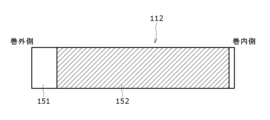
- a negative electrode 112 was fabricated that differed from the example in that the negative electrode substrate exposed portion 62 (see FIG. 4) for the purpose of stress relaxation was not provided.
- This negative electrode 112 has a negative electrode core 151 and negative electrode mixture layers 152 provided on both sides of the negative electrode core 151, and the negative electrode core 151 is exposed at the winding outer end and the winding inner end. It has a core exposed part.
- the negative electrode 112 of the comparative example has a longitudinal length shorter than that of the negative electrode 12 of the example by the longitudinal length of the negative electrode core exposed portion 62 .
- the mixture layer forming region of the negative electrode 112 of the comparative example is the same as the mixture layer forming region of the negative electrode 12 of the example.
- Cylindrical non-aqueous electrolyte secondary battery 110 of Comparative Example has the same configuration as battery 10 of Example except for negative electrode 112 . As shown in FIG. 6 , in the battery 110 of the comparative example, the negative electrode substrate exposed portion sandwiched between the two negative electrode mixture layer forming portions is not present in the non-facing portion 160 of the negative electrode 112 .
Landscapes
- Chemical & Material Sciences (AREA)
- Chemical Kinetics & Catalysis (AREA)
- Electrochemistry (AREA)
- General Chemical & Material Sciences (AREA)
- Engineering & Computer Science (AREA)
- Manufacturing & Machinery (AREA)
- Materials Engineering (AREA)
- Inorganic Chemistry (AREA)
- Secondary Cells (AREA)
Abstract
巻回形の電極体(14)の負極(12)が、正極(11)の巻回方向の始端部(11a)の巻内側との対向部から巻き始め側に正極(11)に対向しない状態で1.25周以上巻回された非対向部(60)を有する。非対向部(60)が、対向部から巻き始め側に向かって順に、負極芯体(51)の少なくとも一方の面に負極合剤層(52)が設けられた第1負極合剤層形成部(61)、負極芯体(51)が露出した第1負極芯体露出部(62)、及び負極芯体(51)の少なくとも一方の面に負極合剤層(52)が設けられた第2負極合剤層形成部(63)を有する。
Description
本開示は、円筒形の非水電解質二次電池に関する。
従来、円筒形の非水電解質二次電池としては、特許文献1に記載されているものがある。この非水電解質二次電池は、負極合剤層が設けられた負極が、電極体の巻内側において正極と対向しない非対向部を有し、その非対向部が2周以上存在している。この非水電解質二次電池は、上記非対向部を巻内側に設けることで電極体の巻内側での変形を抑制している。
円筒形の非水電解質二次電池では、充放電を繰り返した際に正極及び負極が膨張収して、電極体が巻内側で変形することがある。正負極対向部の変形が生じると、正負極間距離が変化し、自己放電量のバラつきが生じる虞がある。そこで、本開示の目的は、正負極対向部の変形を抑制できる円筒形の非水電解質二次電池を提供することにある。
上記課題を解決するため、本開示に係る円筒形の非水電解質二次電池は、正極と負極がセパレータを介して巻回された巻回形の電極体と、非水電解質と、電極体と非水電解質を収容する外装缶とを備え、負極は、正極の巻回方向の始端部の巻内側との対向部から巻き始め側に正極に対向しない状態で1.25周以上巻回された非対向部を含み、非対向部が、対向部側から巻き始め側に向かって順に、負極芯体の少なくとも一方の面に負極合剤層が設けられた第1負極合剤層形成部と、負極芯体が露出した第1負極芯体露出部と、負極芯体の少なくとも一方の面に負極合剤層が設けられた第2負極合剤層形成部とを有し、第1負極合剤層形成部が1周以上巻回されている。
本開示に係る円筒形の非水電解質二次電池によれば、正負極対向部の変形を抑制できる。
以下、図面を参照しながら、本開示に係る円筒形の非水電解質二次電池の実施形態について詳細に説明する。以下で説明する実施形態や変形例の特徴部分を適宜に組み合わせて新たな実施形態を構築することは当初から想定されている。以下の実施形態では、図面において同一構成に同一符号を付し、重複する説明を省略する。また、複数の図面には、模式図が含まれ、異なる図間において、各部材における、縦、横、高さ等の寸法比は、必ずしも一致しない。また、本明細書では、円筒形の非水電解質二次電池10の軸方向(高さ方向)の封口体17側を「上」とし、軸方向の外装缶16の底部68側を「下」とする。以下で説明される構成要素のうち、最上位概念を示す独立請求項に記載されていない構成要素については、任意の構成要素であり、必須の構成要素ではない。また、本開示は、下記実施形態およびその変形例に限定されるものではなく、本願の特許請求の範囲に記載された事項およびその均等な範囲において種々の改良や変更が可能である。
図1は、本開示の一実施形態に係る円筒形の非水電解質二次電池10の軸方向の断面図であり、図2は、非水電解質二次電池10の電極体14の斜視図である。図1に示すように、非水電解質二次電池(以下、単に電池という)10は、巻回型の電極体14、非水電解質(図示せず)、電極体14及び非水電解質を収容する有底筒状で金属製の外装缶16、及び外装缶16の開口部を塞ぐ封口体17を備える。図2に示すように、電極体14は、長尺状の正極11と長尺状の負極12が長尺状の2枚のセパレータ13を介して巻回された巻回構造を有する。
負極12は、リチウムの析出を防止するために、正極11よりも一回り大きな寸法で形成される。即ち、負極12は、正極11より長手方向及び幅方向(短手方向)に長く形成される。また、2枚のセパレータ13は、少なくとも正極11よりも一回り大きな寸法で形成され、例えば正極11を挟むように配置される。負極12は、電極体14の巻き始め端を構成してもよい。しかし、一般的には、セパレータ13が負極12の巻き始め側端を超えて延出し、セパレータ13の巻き始め側端が電極体14の巻き始め端となる。
非水電解質は、非水溶媒と、非水溶媒に溶解した電解質塩とを含む。非水溶媒には、例えばエステル類、エーテル類、ニトリル類、アミド類、およびこれらの2種以上の混合溶媒等を用いてもよい。非水溶媒は、これら溶媒の水素原子の少なくとも一部をフッ素等のハロゲン原子で置換したハロゲン置換体を含有してもよい。なお、非水電解質は液体電解質に限定されず、ゲル状ポリマー等を用いた固体電解質であってもよい。電解質塩には、LiPF6等のリチウム塩が使用される。
正極11は、正極芯体41(図3参照)と、正極芯体41の両面に形成された正極合剤層42(図3参照)とを有する。正極芯体41には、アルミニウム、アルミニウム合金など、正極11の電位範囲で安定な金属箔、当該金属を表層に配置したフィルム等を用いることができる。正極合剤層42は、正極活物質、導電剤、及び結着剤を含む。正極11は、例えば正極芯体41上に正極活物質、導電剤、及び結着剤等を含む正極合剤スラリーを塗布し、塗膜を乾燥させた後、圧縮して正極合剤層42を正極芯体41の両面に形成することにより作製できる。
正極活物質は、リチウム含有金属複合酸化物を主成分として構成される。リチウム含有金属複合酸化物に含有される金属元素としては、Ni、Co、Mn、Al、B、Mg、Ti、V、Cr、Fe、Cu、Zn、Ga、Sr、Zr、Nb、In、Sn、Ta、W等が挙げられる。好ましいリチウム含有金属複合酸化物の一例は、Ni、Co、Mn、Alの少なくとも1種を含有する複合酸化物である。
正極合剤層42に含まれる導電剤としては、カーボンブラック、アセチレンブラック、ケッチェンブラック、黒鉛等の炭素材料が例示できる。正極合剤層42に含まれる結着剤としては、ポリテトラフルオロエチレン(PTFE)、ポリフッ化ビニリデン(PVdF)等のフッ素樹脂、ポリアクリロニトリル(PAN)、ポリイミド樹脂、アクリル樹脂、ポリオレフィン樹脂などが例示できる。これらの樹脂と、カルボキシメチルセルロース(CMC)又はその塩等のセルロース誘導体、ポリエチレンオキシド(PEO)などが併用されてもよい。
図3及び図4に示すように、負極12は、負極芯体51と、負極芯体51の両面に形成された負極合剤層52を有する。負極芯体51には、銅、銅合金など、負極12の電位範囲で安定な金属箔、当該金属を表層に配置したフィルム等を用いることができる。負極合剤層52は、負極活物質、及び結着剤を含む。負極12は、例えば負極芯体51上に負極活物質、及び結着剤等を含む負極合剤スラリーを塗布し、塗膜を乾燥させた後、圧縮して負極合剤層52を負極芯体51の両面に形成することにより作製できる。
負極活物質には、一般的に、リチウムイオンを可逆的に吸蔵、放出する炭素材料が用いられる。好ましい炭素材料は、鱗片状黒鉛、塊状黒鉛、土状黒鉛等の天然黒鉛、塊状人造黒鉛、黒鉛化メソフェーズカーボンマイクロビーズ等の人造黒鉛などの黒鉛である。負極合剤層52には、負極活物質として、ケイ素(Si)を含有するSi材料が含まれていてもよい。また、この場合において、負極合剤層52が、SiOx(0.5≦x≦1.6)で表される酸化ケイ素を含んでもよい。また、負極活物質には、Si以外のリチウムと合金化する金属、当該金属を含有する合金、当該金属を含有する化合物等が用いられてもよい。
負極合剤層52に含まれる結着剤には、正極11の場合と同様に、フッ素樹脂、PAN、ポリイミド樹脂、アクリル樹脂、ポリオレフィン樹脂等を用いてもよいが、好ましくはスチレン-ブタジエンゴム(SBR)又はその変性体を用いる。負極合剤層52には、例えばSBR等に加えて、CMC又はその塩、ポリアクリル酸(PAA)又はその塩、ポリビニルアルコールなどが含まれていてもよい。
セパレータ13には、イオン透過性及び絶縁性を有する多孔性シートが用いられる。多孔性シートの具体例としては、微多孔薄膜、織布、不織布等が挙げられる。セパレータ13の材質としては、ポリエチレン、ポリプロピレン等のポリオレフィン樹脂、セルロースなどが好ましい。セパレータ13は、単層構造、積層構造のいずれでもよい。セパレータ13の表面には、耐熱層などが形成されてもよい。
図1に示すように、正極11には、正極リード20が接合され、負極12の長手方向の巻き始め側には、負極リード21が接合される。電池10は、電極体14の上方に絶縁板18を有し、電極体14の下方に絶縁板19を有する。正極リード20は、絶縁板18の貫通孔を通って封口体17側に延び、負極リード21は、絶縁板19の貫通孔を通って外装缶16の底部68側に延びる。正極リード20は、封口体17の封口板23の下面に溶接等で接続される。封口体17の天板を構成する端子キャップ27が封口板23と電気的に接続され、端子キャップ27が正極端子となる。また、負極リード21は、金属製の外装缶16の底部68の内面に溶接等で接続され、外装缶16が負極端子となる。
本実施形態では、正極リード20を、正極芯体における巻回方向の中央部等の中間部に電気的に接続している。また、負極リード21を、負極芯体51における巻回方向の巻き始め側端部に電気的に接続すると共に負極芯体51における巻回方向の巻き終わり側端部を外装缶16の内面に当接させている。このようにして、負極12の巻き始め側と巻き終わり側の両方を負極端子に電気的に接続することで電流が流れる経路を低減して電気抵抗を低減している。しかし、負極芯体における巻回方向の巻き終わり側端部を外装缶の内面に当接させずに、1つの負極リードを、負極芯体における巻回方向の巻き終わり側端部に電気的に接続してもよい。又は、電極体が2つの負極リードを有して、一方の負極リードを、負極芯体における巻回方向の巻き始め側端部に電気的に接続し、他方の負極リードを、負極芯体における巻回方向の巻き終わり側端部に電気的に接続してもよい。又は、負極リードを用いず、負極芯体における巻回方向の巻き終わり側端部を外装缶の内面に当接させることで、負極と外装缶を電気的に接続してもよい。
電池10は、外装缶16と封口体17との間に配置される樹脂製のガスケット28を更に備える。封口体17は、ガスケット28を介して外装缶16の開口部にかしめ固定される。これにより、電池10の内部空間が密閉される。ガスケット28は、外装缶16と封口体17に挟持され、封口体17を外装缶16に対して絶縁する。ガスケット28は、電池内部の気密性を保つためのシール材の役割と、外装缶16と封口体17を絶縁する絶縁材としての役割を有する。
外装缶16は、電極体14と非水電解質を収容し、肩部38、溝入れ部34、筒状部30、及び底部68を有する。溝入れ部34は、例えば、外装缶16の側面の一部を、径方向内側にスピニング加工して径方向内方側に環状に窪ませることで形成できる。肩部38は、封口体17を外装缶16にかしめ固定する際に、外装缶16の上端部を封口体17の周縁部45に向かって内側に折り曲げて形成される。
封口体17は、電極体14側から順に、封口板23、下弁体24、絶縁部材25、上弁体26、及び端子キャップ27が積層された構造を有する。封口体17を構成する各部材は、例えば円板形状又はリング形状を有し、絶縁部材25を除く各部材は互いに電気的に接続されている。封口板23は、少なくとも1つの貫通孔23aを有する。また、下弁体24と上弁体26は、各々の中央部で接続され、各々の周縁部の間には絶縁部材25が介在している。
電池10が異常発熱して、電池10の内圧が上昇すると、下弁体24が上弁体26を端子キャップ27側に押し上げるように変形して破断し、下弁体24と上弁体26の間の電流経路が遮断される。さらに内圧が上昇すると、上弁体26が破断して、端子キャップ27の貫通孔27aからガスが排出される。このガスの排出により、電池10の内圧が過度に上昇して電池10が破裂することを防止でき、電池10の安全性を高くできる。
図3は、電極体14における巻内側の巻回構造を示す平面図である。なお、図3においては、セパレータの図示を省略している。図3に示すように、負極12は、正極11の巻回方向の始端部11aの巻内側との対向部から巻き始め側に正極11に対向しない状態で1.25周以上巻回された非対向部60を含む。また、非対向部60は、始端部11aの巻内側との対向部から巻き始め側に向かって1周以上巻回されると共に負極芯体51の両面に巻回方向に沿って連続的に負極合剤層52が設けられた第1負極合剤層形成部61を有する。
非対向部60は、更に、第1負極合剤層形成部61から巻き始め側に巻回されると共に負極芯体51が露出した第1負極芯体露出部62と、第1負極芯体露出部62から巻き始め側に巻回されると共に負極芯体51の両面に連続的に負極合剤層52が設けられた第2負極合剤層形成部63とを有する。すなわち、非対向部60は、正極11の始端部11aの巻内側との対向部から巻き始め側に向かって順に、第1負極合剤層形成部61と、第1負極芯体露出部62と、第2負極合剤層形成部63とを有する。第1負極芯体露出部62の長さは特に制限されないが、本実施形態では、第1負極芯体露出部62は0.2周の長さで巻回されている。第1負極芯体露出部62は、0.1周以上かつ0.3周以下の長さで巻き方向に巻回されると好ましい。
非対向部60は、更に第2負極合剤層形成部63から巻き始め側に巻回されると共に負極芯体51が露出した第2負極芯体露出部64を有する。負極リード21は、第2負極芯体露出部64の外周側に接合されている。図4は、長尺状に展開した負極12における一方側面を示す模式平面図である。図4に示すように、非対向部60は、第1負極合剤層形成部61、第1負極芯体露出部62、第2負極合剤層形成部63、及び第2負極芯体露出部64を有する。なお、第1及び第2負極合剤層形成部61,63が、負極芯体51の両面に負極合剤層52を有する場合について説明したが、第1及び第2負極合剤層形成部は、負極芯体51の一方側の面のみに負極合剤層が設けられる構成でもよい。
本実施形態によれば、電池10が、負極12の巻内側における正極11に対向しない非対向部60が負極芯体51の少なくとも一方の面に負極合剤層52が形成された負極合剤層形成部61,63を有する。したがって、電極体14が充放電時を繰り返した際に変形し易い電極体14の巻内側の剛性を大きくできるので、電極体14の巻内側における正負極対向部67の変形を抑制できる。
更には、非対向部60が、第1及び第2負極合剤層形成部61,63に挟まれるように位置する第1負極芯体露出部62を有する。第1負極芯体露出部62は第1及び第2負極合剤層形成部61,63に比べて剛性が低いため、電極体14の巻内側が応力を受けると、第1負極芯体露出部62の応力を緩和するように作用する。第1負極芯体露出部62は正負極対向部67から巻き始め側に1周以上離間するように配置されているため、第1負極芯体露出部62が変形しても正極対向部67の変形は抑制される。
第1負極芯体露出部62は、0.1周以上かつ0.3周以下巻回されていることが好ましい。この構成によれば、非対向部60が剛性を確保しつつ、電極体14の巻内側の応力を緩和して電極体14の巻内側における正負極対向部67の変形が効果的に抑制される。また、負極合剤層52が、SiOx(0.5≦x≦1.6)で表される酸化ケイ素を含んで、負極12の充放電時の膨張収縮が大きい場合には、本開示の技術の作用効果を顕著なものにできる。
<実施例>
[正極の作製]
正極活物質にアルミニウム含有ニッケルコバルト酸リチウム(LiNi0.88Co0.09Al0.03O2)を用いた。まず、正極活物質として100質量部のLiNi0.88Co0.09Al0.03O2、導電助剤として1質量部のアセチレンブラック、結着剤として0.9質量部のポリフッ化ビニリデン(PVDF)を、N-メチルピロリドン(NMP)の溶剤中で混合して、正極スラリーを得た。この正極スラリーを、厚み15μmのアルミニウム箔の両面に均一に塗布した。この際、正極リード20を取り付けるための芯体露出部を設けた。次に、加熱した乾燥機中で熱処理を実施してNMPを除去後、ロールプレス機により圧延した。さらに圧延加工後の正極極板を、熱したロールへと接触させて熱処理を行い、厚み0.179mm、幅62.6mm、長さ703mmに裁断して、正極11を作製した。正極11の芯体露出部に幅3.5mmのアルミニウム製の正極リード20を取り付けた。
[負極の作製]
負極活物質として、黒鉛粉末を95質量部、Si酸化物を5質量部になるように混合した。その負極活物質を100質量部、増粘剤としてCMCを1質量部、結着剤としてスチレンブタジエンゴムを1質量部を水中で混合して、負極スラリーを得た。この負極スラリーを、厚さ8μmの銅箔の負極芯体51の両面に塗布して、負極合剤層52を図4に示すように形成した。この際に、非対向部67を、正極11の始端部11aの巻内側との対向部から、1.75周の範囲に設けた。第1負極合剤層形成部61及び第1負極芯体露出部62は、それぞれ1.25周及び0.2周の範囲に設けた。次いで、負極合剤層52を乾燥した後、負極厚みが0.192mmになるように圧縮ローラで圧縮し、幅64mm、長さ816mmに裁断して負極12を作製した。負極12の第2負極芯体露出部64にニッケル-銅製の負極リード21を取り付けた。
負極活物質として、黒鉛粉末を95質量部、Si酸化物を5質量部になるように混合した。その負極活物質を100質量部、増粘剤としてCMCを1質量部、結着剤としてスチレンブタジエンゴムを1質量部を水中で混合して、負極スラリーを得た。この負極スラリーを、厚さ8μmの銅箔の負極芯体51の両面に塗布して、負極合剤層52を図4に示すように形成した。この際に、非対向部67を、正極11の始端部11aの巻内側との対向部から、1.75周の範囲に設けた。第1負極合剤層形成部61及び第1負極芯体露出部62は、それぞれ1.25周及び0.2周の範囲に設けた。次いで、負極合剤層52を乾燥した後、負極厚みが0.192mmになるように圧縮ローラで圧縮し、幅64mm、長さ816mmに裁断して負極12を作製した。負極12の第2負極芯体露出部64にニッケル-銅製の負極リード21を取り付けた。
[非水電解液の調製]
エチレンカーボネート(EC)とジメチルメチルカーボネート(DMC)からなる混合溶媒(体積比でEC:DMC=1:3)100質量部に、ビニレンカーボネート(VC)を5質量部添加し、LiPF6を1.5モル/リットル溶解して非水電解液を調製した。
エチレンカーボネート(EC)とジメチルメチルカーボネート(DMC)からなる混合溶媒(体積比でEC:DMC=1:3)100質量部に、ビニレンカーボネート(VC)を5質量部添加し、LiPF6を1.5モル/リットル溶解して非水電解液を調製した。
[円筒形電池の組立]
正極11と負極12をポリエチレン製のセパレータ13を介して巻回し、負極12の巻き終り端を含む電極体14の最外周に幅9mm、長さ60.0mmのテープを貼着し、巻回型の電極体14を作製した。図3に示すように、負極12の非対向部60は、第1及び第2負極合剤層形成部61,63の間に第1負極芯体露出部62を有する。電極体14の最外周面に負極12の芯体露出部を配置した。その電極体14の上と下に絶縁板18,19を配置し、負極リード21を外装缶16に溶接すると共に、正極リード20を内圧作動型の安全弁を有する封口板23に溶接して、外装缶16の内部に収納した。その後、外装缶16の内部に非水電解液を減圧方式により注入した。最後に、外装缶16の開口端部に、ガスケット28を介して封口体17をかしめ固定することで円筒形電池(非水電解質二次電池)10を作製した。電池10の容量は4600mAhであった。
正極11と負極12をポリエチレン製のセパレータ13を介して巻回し、負極12の巻き終り端を含む電極体14の最外周に幅9mm、長さ60.0mmのテープを貼着し、巻回型の電極体14を作製した。図3に示すように、負極12の非対向部60は、第1及び第2負極合剤層形成部61,63の間に第1負極芯体露出部62を有する。電極体14の最外周面に負極12の芯体露出部を配置した。その電極体14の上と下に絶縁板18,19を配置し、負極リード21を外装缶16に溶接すると共に、正極リード20を内圧作動型の安全弁を有する封口板23に溶接して、外装缶16の内部に収納した。その後、外装缶16の内部に非水電解液を減圧方式により注入した。最後に、外装缶16の開口端部に、ガスケット28を介して封口体17をかしめ固定することで円筒形電池(非水電解質二次電池)10を作製した。電池10の容量は4600mAhであった。
<比較例>
図5に示すように、応力緩和を目的とした負極芯体露出部62(図4参照)を設けない点のみが、実施例と異なる負極112を作製した。この負極112は、負極芯体151と、負極芯体151の両面に設けられた負極合剤層152を有し、巻外側の端部と巻内側の端部に負極芯体151が露出した負極芯体露出部を有する。比較例の負極112は、実施例の負極12との比較で、長手方向長さが負極芯体露出部62の長手方向長さだけ短くなっている。比較例の負極112の合剤層形成領域は、実施例の負極12の合剤層形成領域と同一である。比較例の円筒形の非水電解質二次電池110は、負極112以外の構成は、実施例の電池10と同一である。図6に示すように、比較例の電池110は、負極112の非対向部160に2つの負極合剤層形成部に挟まれた負極芯体露出部が存在しない。
図5に示すように、応力緩和を目的とした負極芯体露出部62(図4参照)を設けない点のみが、実施例と異なる負極112を作製した。この負極112は、負極芯体151と、負極芯体151の両面に設けられた負極合剤層152を有し、巻外側の端部と巻内側の端部に負極芯体151が露出した負極芯体露出部を有する。比較例の負極112は、実施例の負極12との比較で、長手方向長さが負極芯体露出部62の長手方向長さだけ短くなっている。比較例の負極112の合剤層形成領域は、実施例の負極12の合剤層形成領域と同一である。比較例の円筒形の非水電解質二次電池110は、負極112以外の構成は、実施例の電池10と同一である。図6に示すように、比較例の電池110は、負極112の非対向部160に2つの負極合剤層形成部に挟まれた負極芯体露出部が存在しない。
(サイクル試験)
実施例の電池10と比較例の電池110の夫々を、25℃環境において1380mA(0.3It)の定電流充電にて4.2Vに達した後、4.2Vで終止電流を92mA(0.02It)とした定電圧充電を行い、20分間休止後、放電電流4600mA(1It)で定電流放電を行い、20分間休止する充放電サイクルを500サイクル繰り返した。その後、各電池10,110の電極体14,114の巻内側における正負極対向部67,167の変形が生じているか否かを確認した。
実施例の電池10と比較例の電池110の夫々を、25℃環境において1380mA(0.3It)の定電流充電にて4.2Vに達した後、4.2Vで終止電流を92mA(0.02It)とした定電圧充電を行い、20分間休止後、放電電流4600mA(1It)で定電流放電を行い、20分間休止する充放電サイクルを500サイクル繰り返した。その後、各電池10,110の電極体14,114の巻内側における正負極対向部67,167の変形が生じているか否かを確認した。
(試験結果)

比較例では、正負極対向部167で電極体114の変形が生じていた。これはサイクルに伴って正極11および負極112の膨張収縮が生じ、電極体114の巻内側で正極11及び負極112に応力がかかってしまっていたためだと考えられる。一方、実施例では、負極芯体露出部62が変形していたものの、正負極対向部67では変形が生じていなかった。これは巻内側に設けた負極芯体露出部62へ優先的に応力が集中する事で、正負極対向部67にかかる応力が緩和されたためであると考えられる。よって、この試験より、本開示の電池10によれば、巻内側の正負極対向部67の変形を抑制できることが確認された。
10 電池、 11 正極、 11a 正極の始端部、 12 負極、 13 セパレータ、 14 電極体、 16 外装缶、 17 封口体、 20 正極リード、 21 負極リード、 23 封口板、 27 端子キャップ、 28 ガスケット、 51 負極芯体、 52 負極合剤層、 60 非対向部、 61 第1負極合剤層形成部、 62 第1負極芯体露出部、 63 第2負極合剤層形成部、 64 第2負極芯体露出部、 67 正負極対向部。
Claims (4)
- 正極と負極がセパレータを介して巻回された巻回形の電極体と、
非水電解質と、
前記電極体と前記非水電解質を収容する外装缶とを備え、
前記負極は、前記正極の巻回方向の始端部の巻内側との対向部から巻き始め側に前記正極に対向しない状態で1.25周以上巻回された非対向部を含み、
前記非対向部が、前記対向部側から巻き始め側に向かって順に、負極芯体の少なくとも一方の面に負極合剤層が設けられた第1負極合剤層形成部と、前記負極芯体が露出した第1負極芯体露出部と、前記負極芯体の少なくとも一方の面に負極合剤層が設けられた第2負極合剤層形成部とを有し、
前記第1負極合剤層形成部が1周以上巻回されている、円筒形の非水電解質二次電池。 - 前記第1負極芯体露出部は、0.1周以上0.3周以下巻回されている、請求項1に記載の円筒形の非水電解質二次電池。
- 前記非対向部が、前記第2負極合剤層形成部よりも巻き始め側に前記負極芯体が露出した第2負極芯体露出部を有し、
前記第2負極芯体露出部に負極リードが接合されている、請求項1又は2に記載の円筒形の非水電解質二次電池。 - 前記負極合剤層が、SiOx(0.5≦x≦1.6)で表される酸化ケイ素を含む、請求項1から3のいずれか1つに記載の円筒形の非水電解質二次電池。
Applications Claiming Priority (2)
| Application Number | Priority Date | Filing Date | Title |
|---|---|---|---|
| JP2022-011957 | 2022-01-28 | ||
| JP2022011957 | 2022-01-28 |
Publications (1)
| Publication Number | Publication Date |
|---|---|
| WO2023145674A1 true WO2023145674A1 (ja) | 2023-08-03 |
Family
ID=87471962
Family Applications (1)
| Application Number | Title | Priority Date | Filing Date |
|---|---|---|---|
| PCT/JP2023/001865 WO2023145674A1 (ja) | 2022-01-28 | 2023-01-23 | 円筒形の非水電解質二次電池 |
Country Status (1)
| Country | Link |
|---|---|
| WO (1) | WO2023145674A1 (ja) |
Citations (3)
| Publication number | Priority date | Publication date | Assignee | Title |
|---|---|---|---|---|
| JP2013137946A (ja) * | 2011-12-28 | 2013-07-11 | Panasonic Corp | 非水電解液二次電池 |
| WO2018061381A1 (ja) * | 2016-09-30 | 2018-04-05 | パナソニックIpマネジメント株式会社 | 非水電解質二次電池 |
| JP2020102311A (ja) * | 2018-12-20 | 2020-07-02 | 本田技研工業株式会社 | 捲回型電池および捲回型電池の製造方法 |
-
2023
- 2023-01-23 WO PCT/JP2023/001865 patent/WO2023145674A1/ja unknown
Patent Citations (3)
| Publication number | Priority date | Publication date | Assignee | Title |
|---|---|---|---|---|
| JP2013137946A (ja) * | 2011-12-28 | 2013-07-11 | Panasonic Corp | 非水電解液二次電池 |
| WO2018061381A1 (ja) * | 2016-09-30 | 2018-04-05 | パナソニックIpマネジメント株式会社 | 非水電解質二次電池 |
| JP2020102311A (ja) * | 2018-12-20 | 2020-07-02 | 本田技研工業株式会社 | 捲回型電池および捲回型電池の製造方法 |
Similar Documents
| Publication | Publication Date | Title |
|---|---|---|
| US11502382B2 (en) | Nonaqueous electrolyte secondary battery | |
| WO2019230298A1 (ja) | 非水電解質二次電池 | |
| JP7461878B2 (ja) | 非水電解質二次電池 | |
| JP7321158B2 (ja) | 非水電解質二次電池 | |
| WO2021166925A1 (ja) | 非水電解質二次電池および非水電解質二次電池用負極 | |
| US20230064681A1 (en) | Electrode for secondary batteries, and secondary battery | |
| CN116137936A (zh) | 非水电解质二次电池 | |
| EP3933968B1 (en) | Winding-type nonaqueous electrolyte secondary battery | |
| WO2022202395A1 (ja) | 円筒形電池 | |
| WO2023145674A1 (ja) | 円筒形の非水電解質二次電池 | |
| JP2022152423A (ja) | 円筒形電池 | |
| WO2019244817A1 (ja) | 非水電解質二次電池 | |
| US20210226199A1 (en) | Nonaqueous electrolyte secondary battery | |
| WO2023163097A1 (ja) | 円筒形の非水電解質二次電池 | |
| WO2023163139A1 (ja) | 円筒形の非水電解質二次電池 | |
| WO2023162710A1 (ja) | 円筒形の非水電解質二次電池 | |
| WO2023054005A1 (ja) | 円筒形電池 | |
| US20240088390A1 (en) | Non-aqueous electrolyte secondary battery | |
| WO2022196445A1 (ja) | 非水電解質二次電池 | |
| WO2023054021A1 (ja) | 円筒形電池 | |
| WO2024111410A1 (ja) | 円筒形の非水電解質二次電池 | |
| WO2023145679A1 (ja) | 非水電解質二次電池 | |
| WO2023182170A1 (ja) | 円筒形非水電解質二次電池 | |
| WO2023171600A1 (ja) | 非水電解質二次電池 | |
| WO2021039481A1 (ja) | 非水電解質二次電池及び非水電解質二次電池の製造方法 |
Legal Events
| Date | Code | Title | Description |
|---|---|---|---|
| 121 | Ep: the epo has been informed by wipo that ep was designated in this application |
Ref document number: 23746886 Country of ref document: EP Kind code of ref document: A1 |