WO2019225006A1 - 圧縮機ユニット、空気調和装置の室外機及び空気調和装置 - Google Patents
圧縮機ユニット、空気調和装置の室外機及び空気調和装置 Download PDFInfo
- Publication number
- WO2019225006A1 WO2019225006A1 PCT/JP2018/020169 JP2018020169W WO2019225006A1 WO 2019225006 A1 WO2019225006 A1 WO 2019225006A1 JP 2018020169 W JP2018020169 W JP 2018020169W WO 2019225006 A1 WO2019225006 A1 WO 2019225006A1
- Authority
- WO
- WIPO (PCT)
- Prior art keywords
- compressor
- absorbing material
- sound absorbing
- compressor unit
- unit according
- Prior art date
Links
Images


Classifications
-
- F—MECHANICAL ENGINEERING; LIGHTING; HEATING; WEAPONS; BLASTING
- F24—HEATING; RANGES; VENTILATING
- F24F—AIR-CONDITIONING; AIR-HUMIDIFICATION; VENTILATION; USE OF AIR CURRENTS FOR SCREENING
- F24F1/00—Room units for air-conditioning, e.g. separate or self-contained units or units receiving primary air from a central station
- F24F1/06—Separate outdoor units, e.g. outdoor unit to be linked to a separate room comprising a compressor and a heat exchanger
- F24F1/08—Compressors specially adapted for separate outdoor units
- F24F1/12—Vibration or noise prevention thereof
-
- F—MECHANICAL ENGINEERING; LIGHTING; HEATING; WEAPONS; BLASTING
- F04—POSITIVE - DISPLACEMENT MACHINES FOR LIQUIDS; PUMPS FOR LIQUIDS OR ELASTIC FLUIDS
- F04B—POSITIVE-DISPLACEMENT MACHINES FOR LIQUIDS; PUMPS
- F04B39/00—Component parts, details, or accessories, of pumps or pumping systems specially adapted for elastic fluids, not otherwise provided for in, or of interest apart from, groups F04B25/00 - F04B37/00
-
- F—MECHANICAL ENGINEERING; LIGHTING; HEATING; WEAPONS; BLASTING
- F24—HEATING; RANGES; VENTILATING
- F24F—AIR-CONDITIONING; AIR-HUMIDIFICATION; VENTILATION; USE OF AIR CURRENTS FOR SCREENING
- F24F13/00—Details common to, or for air-conditioning, air-humidification, ventilation or use of air currents for screening
- F24F13/24—Means for preventing or suppressing noise
- F24F2013/242—Sound-absorbing material
Definitions
- the present invention relates to a compressor unit including a sound absorbing material, an outdoor unit of an air conditioner, and an air conditioner.
- an outdoor unit of an air conditioner surrounds a compressor with a sound absorbing material in order to reduce sound radiated from the compressor.
- the suction muffler or the suction pipe is condensed, and the appropriate water is collected in the base of the outdoor unit.
- the compressor corrodes when the sound absorbing material covering the compressor body sucks up water and the compressor touches the sound absorbing material that has absorbed water for a long time. For this reason, it is required that the sound absorbing material does not absorb water.
- Patent Document 1 proposes a sound-absorbing material that is placed on a compressor apart from the base of an outdoor unit and wound directly on a compressor that is a noise source to improve sound absorption.
- the present invention is for solving the above-described problems, and the sound absorbing material can surround substantially the entire side surface of the unit including the compressor and the piping, and can be efficiently assembled to improve workability.
- An object is to provide a compressor unit, an outdoor unit of an air conditioner, and an air conditioner.
- a compressor unit is a compressor unit including a compressor and pipes respectively connected to a suction side and a discharge side of the compressor, and surrounds the periphery of a side surface portion of the compressor unit.
- the sound absorbing material has a plurality of support portions that are respectively supported at at least two locations of the compressor unit, and at least one of the plurality of support portions bends the sound absorbing material to form an upper edge.
- the pipe has a bent portion that connects two vertically extending portions formed in the upper portion of the compressor unit, and the sound absorbing material bends the hook portion to the bent portion.
- the upper part is positioned by being hooked on the part, suspended by the plurality of support parts, and separated from the installation surface of the compressor.
- An outdoor unit of an air conditioner according to the present invention includes the above-described compressor unit.
- An air conditioner according to the present invention includes the outdoor unit of the air conditioner described above.
- the sound absorbing material is positioned at the upper part by hooking the hook part on the bent part and suspended by the plurality of support parts. Separated from the installation surface. For this reason, for example, after welding a compressor and piping, a sound-absorbing material is attached over the whole compressor unit. Therefore, the sound absorbing material can substantially surround the entire side surface of the unit including the compressor and the piping, and the compressor unit can be efficiently assembled to improve workability.
- FIG. 1 It is a perspective view which shows the sound-absorbing material which concerns on Embodiment 1 of this invention. It is a perspective view which shows the state which attaches the sound absorption material which concerns on Embodiment 1 of this invention to a compressor unit. It is a perspective view which shows the state which attaches the upper surface cover and side cover which concern on Embodiment 1 of this invention to a compressor unit. It is a top view which shows the state which surrounded the sound absorption material in the compressor unit which concerns on Embodiment 1 of this invention. It is a top view which shows the internal state of the compressor unit enclosed with the sound-absorbing material which concerns on Embodiment 1 of this invention from the same direction as FIG.
- FIG. 1 It is a perspective view which shows the state which surrounded the compressor unit which concerns on Embodiment 1 of this invention with the sound-absorbing material. It is a perspective view which shows the state which surrounded the compressor unit which concerns on Embodiment 1 of this invention with the sound-absorbing material from the direction different from FIG. It is a side view which shows the state which surrounded the compressor unit which concerns on Embodiment 1 of this invention with the sound-absorbing material. It is a perspective view which expands and shows the hook part of the sound-absorbing material which concerns on Embodiment 1 of this invention. It is a side view which shows the state which surrounded the compressor unit which concerns on Embodiment 1 of this invention with the sound-absorbing material from the direction different from FIG.
- FIG. 1 It is a side view which shows the internal state of the compressor unit enclosed with the sound-absorbing material which concerns on Embodiment 1 of this invention from the same direction as FIG. It is an expanded view which shows one sheet used as the base of the sound-absorbing material which concerns on Embodiment 1 of this invention. It is a side view which shows the state which folded the sheet
- FIG. 1 is a refrigerant circuit diagram showing an air-conditioning apparatus 100 according to Embodiment 1 of the present invention.
- an outdoor unit 101 and an indoor unit 102 are connected by a gas refrigerant pipe 103 and a liquid refrigerant pipe 104.
- the outdoor unit 101 includes a compressor 105, a four-way valve 106, an outdoor heat exchanger 107, and an expansion valve 108.
- Compressor 105 compresses and discharges the sucked refrigerant.
- the compressor 105 may change an operation frequency arbitrarily, for example with an inverter circuit etc., and may change the capacity
- FIG. 1
- the four-way valve 106 is a valve that switches the flow of the refrigerant between, for example, a cooling operation and a heating operation.
- the outdoor heat exchanger 107 performs heat exchange between the refrigerant and the outdoor air.
- the outdoor heat exchanger 107 functions as a condenser during the cooling operation, and condenses and liquefies the refrigerant.
- the outdoor heat exchanger 107 functions as an evaporator during heating operation, and evaporates and evaporates the refrigerant.
- the expansion valve 108 is a flow control valve, and decompresses the refrigerant to expand it.
- the expansion valve 108 is constituted by an electronic expansion valve, for example, the opening degree can be adjusted based on an instruction from a control device (not shown).
- the indoor unit 102 has an indoor heat exchanger 109.
- the indoor heat exchanger 109 performs heat exchange between air to be air-conditioned and a refrigerant, for example.
- the indoor heat exchanger 109 functions as an evaporator during the cooling operation, and evaporates and evaporates the refrigerant.
- the indoor heat exchanger 109 functions as a condenser during heating operation, and condenses and liquefies the refrigerant.
- the refrigerant flow is switched by the four-way valve 106 of the outdoor unit 101, and the cooling operation or the heating operation can be realized.
- FIG. 2 is an exploded perspective view showing the outdoor unit 101 of the air-conditioning apparatus 100 according to Embodiment 1 of the present invention.
- FIG. 3 is an exploded perspective view showing a state in which the soundproof structure 20 of the compressor unit 14 in the outdoor unit 101 of the air-conditioning apparatus 100 according to Embodiment 1 of the present invention is excluded.
- the outdoor unit 101 includes a rectangular parallelepiped housing 1 that houses various components therein.
- the casing 1 of the outdoor unit 101 has a top panel 2 at the top when viewed from the front.
- the housing 1 has a base 3 on the bottom surface.
- the housing 1 has a front panel 4 on the front side.
- the front panel 4 is formed with a circular opening 4 a that sucks air into the blower fan 15.
- a lattice-shaped fan guard 5 is attached to the opening 4a on the outer front side.
- the housing 1 has a left side panel 6 that is bent to the left side as viewed from the front side next to the front panel 4.
- the housing 1 has a right side panel 7 on the right side as viewed from the front.
- the outdoor unit 101 has a blower chamber 8 on the left side when viewed from the front.
- the outdoor unit 101 has a machine room 9 on the right side when viewed from the front.
- the blower chamber 8 and the machine chamber 9 are separated by a separator 10.
- a compressor 105, a pipe 11, a suction muffler 12, an electrical component box 13, and other parts are arranged in the machine room 9.
- the refrigerant flowing from the gas refrigerant pipe 103 or the liquid refrigerant pipe 104 into the machine chamber 9 is sent to the compressor 105 through the pipe 11 via the suction muffler 12.
- the refrigerant is compressed by the compressor 105, passes through the discharge-side piping 11, and is sent to either the outdoor heat exchanger 107 or the indoor heat exchanger 109.
- the electrical component box 13 supplies power to each component.
- the compressor 105, the pipe 11, and the suction muffler 12 are configured as a compressor unit 14 covered with a soundproof structure 20. Details of the soundproof structure 20 will be described later.
- the blower chamber 8 includes an outdoor heat exchanger 107, a blower fan 15, a fan motor (not shown), a motor support (not shown), and other components.
- the outdoor heat exchanger 107 is L-shaped when viewed from above, and is disposed on the back side of the blower chamber 8, which is behind the blower fan 15.
- the outdoor heat exchanger 107 is disposed on the back side inside the housing 1 and on the left side when viewed from the front.
- the fan motor rotationally drives the blower fan 15.
- the motor support fixes the fan motor.
- FIG. 4 is a perspective view showing the compressor unit 14 according to Embodiment 1 of the present invention.
- the compressor unit 14 disposed in the outdoor unit 101 includes a compressor 105, a pipe 11, and a suction muffler 12.
- the compressor unit 14 is surrounded by the soundproof structure 20 in the installed state.
- piping 11 of compressor unit 14 As the piping 11, a piping 11 a connected to the suction side of the compressor 105, a piping 11 b connected to the discharge side of the compressor 105, and a piping 11 c connected to the indoor heat exchanger 109 or the outdoor heat exchanger 107. And having.
- a pipe 11 a connected to the suction side of the compressor 105 is connected to the lower outer peripheral surface of the compressor 105, extends upward, and has a suction muffler 12 in the middle.
- a pipe 11 a connected to the suction side of the compressor 105 connects a portion extending in the vertical direction having the suction muffler 12 and a portion extending in the vertical direction next to the suction muffler 12, and is connected to the compressor 105, which is an upper portion of the compressor unit 14. It has the bending part 16 located higher than an upper surface.
- the bent portion 16 is a portion where the pipe 11a is bent in a U shape that is convex upward.
- the portion of the pipe 11 provided with the suction muffler 12 and the portion of the pipe 11 extending downward from the bent portion 16 are a vertically extending portion 17 a extending in the vertical direction next to the compressor 105.
- the pipe 11b connected to the discharge side of the compressor 105 connects the upper portion of the compressor 105 and extends in the vertical direction to the upper portion of the compressor unit 14 that is adjacent to the portion extending in the vertical direction.
- the bent portion 16 is located higher than the upper surface of the compressor 105.
- the bent portion 16 is a portion where the pipe 11b is bent in a U shape that is convex upward.
- a portion extending downward from the bent portion 16 is a vertically extending portion 17 b that extends vertically next to the compressor 105.
- FIG. 5 is a perspective view showing the compressor unit 14 including the soundproof structure 20 mounted on the base 3 according to Embodiment 1 of the present invention.
- FIG. 6 is an exploded perspective view showing the soundproof structure 20 according to Embodiment 1 of the present invention.
- the compressor unit 14 is disposed on the base 3 so as to be surrounded by a soundproof structure 20.
- the soundproof structure 20 is intended for soundproofing or sound insulation of noise generated by the compressor 105.
- the soundproof structure 20 includes an upper surface cover 21, a side surface cover 22, and a sound absorbing material 23.
- the sound absorbing material 23 surrounds the compressor unit 14 inside the side cover 22.
- the side cover 22 covers and covers the outside of the sound absorbing material 23.
- the upper surface cover 21 covers the upper part of the compressor unit 14 according to the outer peripheral edge of the side surface cover 22.
- the upper surface cover 21 closes the upper surface of the sound absorbing material 23.
- the upper surface cover 21 is made of a rubber member for the purpose of sound insulation and waterproofing.
- the upper surface cover 21 has a flat plate shape and has a hole for extending the pipe 11 connected to the compressor 105 to the outside.
- the side cover 22 is overlaid on the outside of the sound absorbing material 23.
- the side cover 22 is made of a rubber member for sound insulation and waterproofing purposes.
- the side cover 22 surrounds the side of the compressor unit 14 so as to wrap around the outer periphery around the trunk of the compressor unit 14 surrounded by the sound absorbing material 23.
- the side cover 22 is open at a part of the side of the compressor unit 14 that can be sound-insulated by the separator 10.
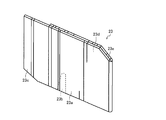
- FIG. 7 is a perspective view showing the sound absorbing material 23 according to Embodiment 1 of the present invention.
- the sound absorbing material 23 is arranged inside the upper surface cover 21 and spaced from the base 3 that is the installation surface of the compressor unit 14, and covers the compressor unit 14 together with the side cover 22. Yes.
- the sound absorbing material 23 covers the entire inner peripheral area of the side cover 22.
- the sound absorbing material 23 is made of a felt member for the purpose of sound absorption. Since the upper side of the sound absorbing material 23 is covered by the upper surface cover 21, the water dripped from the pipe 11 does not land on the sound absorbing material 23, and the dripped water is reliably received by the upper surface cover 21.
- the compressor Since the sound absorbing material 23 is arranged away from the base 3 and the upper side is covered with the upper surface cover 21, the compressor does not absorb water even when a felt material having high sound absorbing properties is used, and the absorbed sound absorbing material 23 contacts. 105 is not corroded.
- the sound-absorbing material 23 covers the outside of the portion of the slit 23b that protrudes from the tubular portion 23a, a cylindrical portion 23a that surrounds substantially the entire compressor unit 14, a slit 23b that extends the pipe 11 from the tubular portion 23a. And an overlapping portion 23c.
- the cylindrical portion 23 a surrounds the entire periphery of the side surface portion of the compressor unit 14 including the compressor 105, the vertically extending portions 17 a and 17 b of the pipe 11, and the suction muffler 12. That is, the cylindrical portion 23a covers substantially the entire compressor unit 14 including various components and spaces therebetween.
- the cylindrical portion 23 a is formed in a cylindrical shape by joining one end portion of the sound absorbing material 23 to the main body portion of the sound absorbing material 23.
- the joining method for joining one end of the sound absorbing material 23 to the main body may be any means such as sewing or fixing with a string.
- One hook portion 23d that is closed in an annular shape is provided on the upper portion of the cylindrical portion 23a.
- the sound absorbing material 23 has a slit 23 b that extends the pipe 11 to the outside of the compressor unit 14 covered with the sound absorbing material 23 from the lower part of the vertically extending portion 17 a of the pipe 11 disposed next to the compressor 105. .
- the slit 23 b opens from the lower end of the sound absorbing material 23.
- the sound absorbing material 23 has an overlapping portion 23c that covers the outside of the slit 23b.
- the overlapping portion 23c is formed in a single piece at the other end portion of the sound absorbing material 23 extended from the cylindrical portion 23a formed in a cylindrical shape by the one end portion and the main body portion.
- the overlapping portion 23c has a size that covers the slit 23b.
- the soundproof structure 20 covers the compressor unit 14 after the compressor unit 14 to which the pipe 11 and the like are connected by welding is assembled on the base 3. First, the sound absorbing material 23 surrounds the compressor unit 14. Next, the side cover 22 and the top cover 21 cover the compressor unit 14 surrounded by the sound absorbing material 23.
- FIG. 8 is a perspective view showing a state in which the sound absorbing material 23 according to Embodiment 1 of the present invention is attached to the compressor unit 14.
- a compressor 105, a pipe 11, a suction muffler 12, and the like are arranged in the machine room 9 of the outdoor unit 101.
- the range which puts the sound-absorbing material 23 is narrow. Therefore, the sound absorbing material 23 is covered from above the compressor unit 14 in a state after the pipe 11 and the suction muffler 12 are connected to the compressor 105, and the entire periphery of the side surface portion of the compressor unit 14 is cylindrical. Surrounded by the shaped portion 23a.
- FIG. 9 is a perspective view illustrating a state in which the top cover 21 and the side cover 22 according to Embodiment 1 of the present invention are attached to the compressor unit 14.
- the side cover 22 further covers the compressor unit 14 surrounded by the sound absorbing material 23 from the outer peripheral side.
- the top cover 21 covers the compressor unit 14 covered with the side cover 22 from above.
- FIG. 10 is a top view showing a state in which the compressor unit 14 according to Embodiment 1 of the present invention is surrounded by the sound absorbing material 23.
- FIG. 11 is a top view showing the internal state of the compressor unit 14 surrounded by the sound absorbing material 23 according to Embodiment 1 of the present invention from the same direction as FIG.
- FIG. 12 is a perspective view showing a state in which the compressor unit 14 according to Embodiment 1 of the present invention is surrounded by the sound absorbing material 23.
- FIG. 13 is a perspective view illustrating a state in which the compressor unit 14 according to Embodiment 1 of the present invention is surrounded by the sound absorbing material 23 from a direction different from that in FIG. 12.
- FIG. 14 is a side view showing a state in which the compressor unit 14 according to Embodiment 1 of the present invention is surrounded by the sound absorbing material 23.
- FIG. 15 is an enlarged perspective view showing the hook 23d of the sound absorbing material 23 according to Embodiment 1 of the present invention.
- the sound absorbing material 23 has two support portions 18 that are supported at two locations of the compressor unit 14, respectively.
- the two support portions 18 suspend the sound absorbing material 23 and float the lower end of the sound absorbing material 23 away from the base 3 that is the installation surface of the compressor 105.
- the two support portions 18 are formed so that one support portion 18 and the other support portion 18 are opposite to each other with respect to the compressor unit 14. Note that the number of support portions 18 may be two or more.
- one of the two support portions 18 is a hook portion 23 d formed by bending the sound absorbing material 23 and joining the upper edge portion.
- the hook portion 23d has an annular shape with a smaller diameter in the distal direction, and has an opening 23e at the distal end.
- the hook portion 23 d is positioned higher than the upper surface of the compressor 105 by connecting two vertically extending portions formed on the upper portion of the compressor unit 14 of the pipe 11. The bent part 16 is caught. That is, the hook portion 23d is hooked on the bent portion 16 bent in a U shape so that the pipe 11 is convex upward. As shown in FIG.
- the hook part 23d hooked on the bent part 16 exposes the pipe 11 of the bent part 16 from the opening part 23e.
- the operator can confirm the presence of the pipe 11, and the sound absorbing material 23 is positioned by fitting the opening 23 e into the bent portion 16. That is, the sound absorbing material 23 is hung so as not to drop while surrounding the entire periphery of the side surface portion by the two support portions 18 by hooking the hook portion 23d to the bent portion 16 and positioning the upper portion. ing.
- the other support portion 18 of the two support portions 18 is the outer periphery of the compressor 105 at a position facing the hook portion 23d with the compressor unit 14 as the center. It sticks to the surface.
- the hook portion 23d hooked on the bent portion 16 and the support portion 18 attached to the outer peripheral surface of the compressor 105 are pulled together, and the sound absorbing material 23 made of the felt material does not shift, and the substantially entire compressor unit 14 is moved. Can be hung while enclosing. Further, since the sound absorbing material 23 is in close contact with the compressor 105, it is easy to absorb the noise of the compressor 105 serving as a noise source.
- the sound absorbing material 23 surrounds the compressor unit 14 including the compressor 105, the vertically extending portions 17a and 17b, and the suction muffler 12 throughout.
- the sound absorbing material 23 is attached from above the compressor unit 14 after the compressor 105 and the pipe 11 are welded.
- FIGS. 12 shows that a slit 23 b formed in a lower portion of a sound absorbing material 23 attached to substantially the entire compressor unit 14 is connected to the compressor 105. 11 is extended to the outside of the sound absorbing material 23.
- the annularly closed hook 23 d of the sound absorbing material 23 is held by the bent portion 16 of the pipe 11 connected to the compressor 105 so that the sound absorbing material 23 does not fall downward. doing.
- the plate-like overlapping portion 23c extending from the sound absorbing material 23 is located outside the slit 23b to prevent sound leakage from the slit 23b.
- the sound absorbing material 23 does not touch the base 3 because the sound absorbing material 23 is hooked and held by the bent portion 16 of the pipe 11 connected to the compressor 105. For this reason, it is possible to prevent the sound absorbing material 23 from absorbing the water on the base 3 from absorbing the water. Moreover, since the sound absorbing material 23 has the cylindrical part 23a, the compressor 105 and the pipe 11 are welded to each other, and is attached from above the compressor unit 14 over the entire compressor unit 14. Furthermore, since the sound absorbing material 23 has the slit 23b, the piping 11 at the place where the sound absorbing material 23 is disposed can be avoided, and the workability of attaching the sound absorbing material 23 is improved. And the sound leakage from the slit 23b can be absorbed by arrange
- FIG. 18 is a development view showing one sheet as a base of the sound absorbing material 23 according to Embodiment 1 of the present invention.
- FIG. 19 is a side view showing a state in which the cylindrical portion 23a and the overlapping portion 23c are formed by folding one sheet that is a base of the sound absorbing material 23 according to Embodiment 1 of the present invention.
- FIG. 20 shows a state in which the cylindrical portion 23a and the overlapping portion 23c are formed by folding one sheet that is the basis of the sound absorbing material 23 according to Embodiment 1 of the present invention, and the cylindrical portion 23a is not expanded. It is a perspective view.
- the sound absorbing material 23 is formed by processing one sheet. For this reason, unnecessary processing or parts are not required, and the manufacturing efficiency is good.
- the opening 23e of the hook portion 23d, the cuts on both sides of the hook portion 23d, and the slits 23b are punched out.
- the sheet that is the base of the sound absorbing material 23 is folded at one end side, protrudes from the other end side, and joined at one end to the main body portion to form a cylindrical portion 23a. Moreover, the upper end part of the hook part 23d is joined. If the sound absorbing material 23 is a felt material, it may be sewn together.
- the sound absorbing material 23 in which the cylindrical portion 23a and the hook portion 23d are formed has been processed, so that when the sound absorbing material 23 is erected, it has a sheet shape that is folded twice. As shown in FIG. 7, when the cylindrical portion 23 a is expanded in a circular shape so as to create a space inside, the sound absorbing material 23 is covered with the compressor unit 14.
- the compressor unit 14 includes the pipes 11 connected to the compressor 105 and the suction side and the discharge side of the compressor 105, respectively.
- the compressor unit 14 includes a sound absorbing material 23 that surrounds the periphery of the side surface of the compressor unit 14.
- the sound absorbing material 23 includes a plurality of support portions 18 that are respectively supported at at least two locations of the compressor unit 14. At least one of the plurality of support portions 18 is a hook portion 23d in which the sound absorbing material 23 is bent and the upper edge portion is joined.
- the pipe 11 has a bent portion 16 that connects two vertically extending portions formed in the upper portion of the compressor unit 14.
- the sound absorbing material 23 is hooked by the hook portion 23 d to the bent portion 16, is positioned at the top, is suspended by the plurality of support portions 18, and is separated from the base 3 that is the installation surface of the compressor 105.
- the sound absorbing material 23 is attached over the entire periphery of the side surface of the compressor unit 14. Therefore, the sound absorbing material 23 can surround substantially the entire side surface of the compressor unit 14 including the compressor 105 and the pipe 11, and the compressor unit 14 can be efficiently assembled to improve workability.
- the hook portion 23 d is hooked on the bent portion 16 of the pipe 11, the sound absorbing material 23 is suspended by the two support portions 18, and the sound absorbing material 23 is separated from the base 3 which is the installation surface of the compressor 105. .
- the sound absorbing material 23 does not suck the water of the base 3 of the outdoor unit 101 which is the installation surface of the compressor 105. Therefore, the compressor 105 does not touch the sound absorbing material 23 that has absorbed water, and the compressor 105 does not corrode. Further, since the sound absorbing material 23 is suspended by the two support portions 18, the holding state of the suspended sound absorbing material 23 is stabilized.
- the hooking portion 23d is located on the upper part of the sound absorbing material 23, the sound absorbing material 23 is attached so as to be covered from above the compressor unit 14. Furthermore, since the hook part 23d is located at the upper part of the sound absorbing material 23, the suspended sound absorbing material 23 does not fall.
- the pipe 11 has the vertically extending portions 17a and 17b extending in the vertically direction next to the compressor 105.
- the sound absorbing material 23 surrounds the entire periphery of the side surface portion of the compressor unit 14 including the compressor 105 and the vertically extending portions 17a and 17b.
- the sound absorbing material 23 can surround the entire periphery of the side surface portion of the compressor unit 14 including the compressor 105 and the vertically extending portions 17a and 17b, and the compressor unit 14 is efficiently assembled. Workability can be improved.
- the sound absorbing material 23 has the slits 23b for extending the pipe 11 to the outside of the compressor unit 14 from the lower portion of the vertical extending portion 17a.
- the pipe 11 after being connected to the compressor 105 from the slit 23b can be pulled out to the outside of the sound absorbing material 23.
- tube 11 after connecting to the compressor 105 does not worsen the operation
- the sound absorbing material 23 has the overlapping portion 23c that covers the outside of the slit 23b.
- the overlapping portion 23c covers the outside of the slit 23b, and sound leakage from the slit 23b can be suppressed.
- the bent portion 16 is positioned higher than the upper surface of the compressor 105.
- the hook portion 23d is hooked on the bent portion 16 of the pipe 11 located above the compressor 105, and the sound absorbing material 23 is suspended by the two support portions 18. Further, since the hooking portion 23d is located on the upper part of the sound absorbing material 23, the sound absorbing material 23 is attached to the compressor unit 14 from above, and finally the hooking portion 23d is hooked on the bent portion 16. Further, since the hooking portion 23d is positioned on the upper part of the sound absorbing material 23, the hooking portion 23d is hooked on the bent portion 16 so that the upper portion of the sound absorbing material 23 is positioned, and the suspended sound absorbing material 23 does not fall.
- the hook part 23d has the opening part 23e.
- the pipe 11 hooked on the hook portion 23d can be seen from the opening 23e, and the operator can confirm the presence of the pipe 11. Further, the pipe 11 of the bent portion 16 is fitted into the opening 23e, and the sound absorbing material 23 can be positioned.
- the two support portions 18 are formed such that one support portion 18 and the other support portion 18 are opposite to each other with respect to the compressor unit 14.
- the compressor unit 14 includes the compressor 105 and the pipe 11, and the entire compressor unit 14 is a wide range having a gap.
- the two support portions 18 are formed on the opposite sides with respect to the compressor unit 14, even if there is a gap in the compressor unit 14, the two support portions 18 are not connected to the compressor.
- the unit 14 can be supported so as to surround substantially the whole.
- At least one of the two support portions 18 sticks to the outer peripheral surface of the compressor 105.
- At least one of the two support portions 18 sticks to the outer peripheral surface of the compressor 105, and the sound absorbing material 23 is suspended by the two support portions 18.
- the compressor unit 14 includes the suction muffler 12.
- the sound absorbing material 23 surrounds the periphery of the side surface portion of the compressor unit 14 including the suction muffler 12.
- the sound absorbing material 23 can be surrounded over the periphery of the side surface portion of the compressor unit 14 including the suction muffler 12, and the compressor unit 14 can be efficiently assembled to improve workability.
- the sound absorbing material 23 includes a cylindrical portion 23a that surrounds the periphery of the side surface portion of the compressor unit 14, a slit 23b that extends the pipe 11 from the cylindrical portion 23a, and the cylindrical portion 23a. And an overlapping portion 23c that protrudes and covers the outside of the slit 23b.
- the cylindrical portion 23a surrounds the compressor unit 14 throughout. Further, the pipe 11 after being connected to the compressor 105 from the slit 23b can be pulled out to the outside of the cylindrical portion 23a. Furthermore, the overlapping portion 23c covers the outside of the slit 23b, and sound leakage from the slit 23b can be suppressed.
- the cylindrical portion 23 a is formed in a cylindrical shape by joining one end portion of the sound absorbing material 23 to the main body portion of the sound absorbing material 23.
- the overlapping portion 23c is formed in a single piece at the other end portion of the sound absorbing material 23 extended from the cylindrical portion 23a.
- the cylindrical portion 23a surrounds substantially the entire compressor unit 14. Further, the overlapping portion 23c is formed in a single piece at the other end portion of the sound absorbing material 23 extended from the cylindrical portion 23a. For this reason, the shape of the sound absorbing material 23 can be simplified, the sound absorbing material 23 can be easily created, and the cost can be reduced.
- the upper surface cover 21 that closes the upper surface of the sound absorbing material 23 is provided.
- the upper surface cover 21 can prevent the ingress of the water dripping from above into the compressor unit 14.
- the side cover 22 is provided on the outside of the sound absorbing material 23.
- the side cover 22 further improves sound absorption.
- the sound absorbing material 23 surrounds the periphery of the side surface portion of the compressor unit 14 in a state after the pipe 11 is connected to the compressor 105.
- the compressor unit 14 can be efficiently assembled and workability can be improved.
- the sound absorbing material 23 is formed by processing one sheet.
- the shape of the sound absorbing material 23 can be simplified, the sound absorbing material 23 can be easily created, and the cost can be reduced.
- the outdoor unit 101 of the air conditioning apparatus 100 includes the compressor unit 14 described above.
- the sound absorbing material 23 is attached over the entire compressor unit 14. Therefore, the sound absorbing material 23 can be surrounded over the periphery of the side surface portion of the compressor unit 14 including the compressor 105 and the pipe 11, and the compressor unit 14 can be efficiently assembled to improve workability.
- the air conditioner 100 includes the outdoor unit 101 of the air conditioner 100 described above.
- the sound absorbing material 23 is attached over the entire compressor unit 14, for example, after the compressor 105 and the pipe 11 are welded. Therefore, the sound absorbing material 23 can be surrounded over the periphery of the side surface portion of the compressor unit 14 including the compressor 105 and the pipe 11, and the compressor unit 14 can be efficiently assembled to improve workability.
Landscapes
- Engineering & Computer Science (AREA)
- Mechanical Engineering (AREA)
- General Engineering & Computer Science (AREA)
- Chemical & Material Sciences (AREA)
- Combustion & Propulsion (AREA)
- Compressor (AREA)
Abstract
圧縮機ユニットは、圧縮機及び圧縮機の吸入側と吐出側とにそれぞれ接続された配管を備える圧縮機ユニットであって、圧縮機ユニットの側面部の周囲にわたって取り囲む吸音材を備え、吸音材は、圧縮機ユニットの少なくとも2か所にてそれぞれ支持される複数の支持部を有し、複数の支持部の少なくとも1つは、吸音材を折り曲げて上縁部を接合された引っ掛け部であり、配管は、当該圧縮機ユニットの上部に形成された2つの上下方向に延びる部分を繋ぐ屈曲部を有し、吸音材は、引っ掛け部を屈曲部に引っ掛けて上部を位置決めされ、複数の支持部によって吊り下げられて圧縮機の設置面と離間する。
Description
本発明は、吸音材を備える圧縮機ユニット、空気調和装置の室外機及び空気調和装置に関する。
一般的に空気調和装置の室外機は、圧縮機から放射される音を低減するために、圧縮機周囲を吸音材で囲っている。
ここで、圧縮機が運転して吸入マフラー又は吸入配管が結露し、適下した水が室外機のベースに溜まる。このとき、圧縮機本体を覆う吸音材が水を吸い上げ、水を吸った吸音材に圧縮機が長時間触れることにより、圧縮機が腐食する問題がある。このため、吸音材が吸水しないことが要求される。
特許文献1には、室外機のベースと離間して圧縮機に被せ、騒音源である圧縮機に直接巻き付けて吸音性を高めた吸音材が提案されている。
しかしながら、特許文献1の技術では、圧縮機周辺の配管が吸音材を巻き付ける作業性を悪化させるため、圧縮機と配管とを溶接する前に吸音材を取り付ける必要があった。そして、圧縮機に吸音材を巻き付けた後に圧縮機と配管とを溶接する際に、吸音材に溶接時の火が当たらないように形状を上手く設計する必要がある。あるいは、吸音材に難燃性の高い素材を用いる必要がある。
本発明は、上記課題を解決するためのものであり、吸音材が圧縮機及び配管を備えるユニットの側面部の周囲にわたって略全体を取り囲むことができ、効率良く組立てられて作業性の向上が図れる圧縮機ユニット、空気調和装置の室外機及び空気調和装置を提供することを目的とする。
本発明に係る圧縮機ユニットは、圧縮機及び前記圧縮機の吸入側と吐出側とにそれぞれ接続された配管を備える圧縮機ユニットであって、前記圧縮機ユニットの側面部の周囲にわたって取り囲む吸音材を備え、前記吸音材は、前記圧縮機ユニットの少なくとも2か所にてそれぞれ支持される複数の支持部を有し、前記複数の支持部の少なくとも1つは、前記吸音材を折り曲げて上縁部を接合された引っ掛け部であり、前記配管は、当該圧縮機ユニットの上部に形成された2つの上下方向に延びる部分を繋ぐ屈曲部を有し、前記吸音材は、前記引っ掛け部を前記屈曲部に引っ掛けて上部を位置決めされ、前記複数の支持部によって吊り下げられて前記圧縮機の設置面と離間するものである。
本発明に係る空気調和装置の室外機は、上記の圧縮機ユニットを備えるものである。
本発明に係る空気調和装置は、上記の空気調和装置の室外機を備えるものである。
本発明に係る圧縮機ユニット、空気調和装置の室外機及び空気調和装置によれば、吸音材は、引っ掛け部を屈曲部に引っ掛けて上部を位置決めされ、複数の支持部によって吊り下げられて圧縮機の設置面と離間する。このため、たとえば圧縮機と配管とを溶接した後に吸音材が圧縮機ユニットの全体にわたって取り付けられる。したがって、吸音材が圧縮機及び配管を備えるユニットの側面部の周囲にわたって略全体を取り囲むことができ、圧縮機ユニットが効率良く組立てられて作業性の向上が図れる。
以下、図面に基づいて本発明の実施の形態について説明する。なお、各図において、同一の符号を付したものは、同一の又はこれに相当するものであり、これは明細書の全文において共通している。また、断面図の図面においては、視認性に鑑みて適宜ハッチングを省略している。さらに、明細書全文に示す構成要素の形態は、あくまで例示であってこれらの記載に限定されるものではない。
実施の形態1.
<空気調和装置100の構成>
図1は、本発明の実施の形態1に係る空気調和装置100を示す冷媒回路図である。図1に示す空気調和装置100は、室外機101と室内機102とをガス冷媒配管103及び液冷媒配管104によって接続されている。
<空気調和装置100の構成>
図1は、本発明の実施の形態1に係る空気調和装置100を示す冷媒回路図である。図1に示す空気調和装置100は、室外機101と室内機102とをガス冷媒配管103及び液冷媒配管104によって接続されている。
室外機101は、圧縮機105、四方弁106、室外熱交換器107及び膨張弁108を有する。
圧縮機105は、吸入した冷媒を圧縮して吐出する。圧縮機105は、たとえばインバータ回路などにより、運転周波数を任意に変化させ、圧縮機105の単位時間あたりの冷媒を送り出す容量を変化させてもよい。
四方弁106は、たとえば冷房運転時と暖房運転時とによって冷媒の流れを切り換える弁である。
室外熱交換器107は、冷媒と室外の空気との熱交換を行う。室外熱交換器107は、冷房運転時に凝縮器として機能し、冷媒を凝縮して液化させる。室外熱交換器107は、暖房運転時に蒸発器として機能し、冷媒を蒸発させて気化させる。
膨張弁108は、流量制御弁であり、冷媒を減圧して膨張させる。膨張弁108は、たとえば電子式膨張弁などで構成された場合には、図示しない制御装置などの指示に基づいて開度調整を行える。
室内機102は、室内熱交換器109を有する。室内熱交換器109は、たとえば空調対象の空気と冷媒との熱交換を行う。室内熱交換器109は、冷房運転時に蒸発器として機能し、冷媒を蒸発させて気化させる。室内熱交換器109は、暖房運転時に凝縮器として機能し、冷媒を凝縮して液化させる。
以上のように空気調和装置100を構成することにより、室外機101の四方弁106によって冷媒の流れを切り換え、冷房運転又は暖房運転が実現できる。
<空気調和装置100の室外機101の構成>
図2は、本発明の実施の形態1に係る空気調和装置100の室外機101を示す分解斜視図である。図3は、本発明の実施の形態1に係る空気調和装置100の室外機101における圧縮機ユニット14の防音構造体20を除外した状態を示す分解斜視図である。
図2は、本発明の実施の形態1に係る空気調和装置100の室外機101を示す分解斜視図である。図3は、本発明の実施の形態1に係る空気調和装置100の室外機101における圧縮機ユニット14の防音構造体20を除外した状態を示す分解斜視図である。
<室外機の筐体>
図2、図3に示すように、室外機101は、内部に各種部品を収納する直方体の筐体1を備える。室外機101の筐体1は、正面から見て、上部に天面パネル2を有する。筐体1は、底面にベース3を有する。筐体1は、正面側に正面パネル4を有する。正面パネル4には、送風ファン15に吸気する円形状の開口部4aが形成されている。開口部4aには、正面外側に格子状のファンガード5が取付けられている。筐体1は、正面パネル4の隣から正面から見て左側面に屈曲して左側面パネル6を有する。筐体1は、正面から見て右側面に右側面パネル7を有する。
図2、図3に示すように、室外機101は、内部に各種部品を収納する直方体の筐体1を備える。室外機101の筐体1は、正面から見て、上部に天面パネル2を有する。筐体1は、底面にベース3を有する。筐体1は、正面側に正面パネル4を有する。正面パネル4には、送風ファン15に吸気する円形状の開口部4aが形成されている。開口部4aには、正面外側に格子状のファンガード5が取付けられている。筐体1は、正面パネル4の隣から正面から見て左側面に屈曲して左側面パネル6を有する。筐体1は、正面から見て右側面に右側面パネル7を有する。
<室外機101の内部構成>
図2、図3に示すように、室外機101は、正面から見て左側に送風機室8を有する。室外機101は、正面から見て右側に機械室9を有する。送風機室8と機械室9とは、セパレータ10により、仕切られて分けられている。
図2、図3に示すように、室外機101は、正面から見て左側に送風機室8を有する。室外機101は、正面から見て右側に機械室9を有する。送風機室8と機械室9とは、セパレータ10により、仕切られて分けられている。
図3に示すように、機械室9には、圧縮機105と、配管11と、吸入マフラー12と、電気品箱13と、その他の部品と、が配置される。機械室9内にガス冷媒配管103又は液冷媒配管104から流入する冷媒は、吸入マフラー12を介して配管11を通って圧縮機105に送られる。冷媒は、圧縮機105により圧縮され、吐出側の配管11を通り、室外熱交換器107又は室内熱交換器109のいずれかに送られる。また、電気品箱13は、各部品への電力供給などを行う。
図2に示すように、圧縮機105と配管11と吸入マフラー12とは、防音構造体20に覆われた圧縮機ユニット14に構成されている。防音構造体20の詳細は、後述する。
図2、図3に示すように、送風機室8には、室外熱交換器107と、送風ファン15と、図示しないファンモーターと、図示しないモーターサポートと、その他の部品と、が配置される。室外熱交換器107は、上から見てL字形状であり、送風ファン15よりも後ろ側である送風機室8の背面側に配置される。室外熱交換器107は、筐体1内部の背面側と正面から見て左側とに配置されている。ファンモーターは、送風ファン15を回転駆動する。モーターサポートは、ファンモーターを固定する。
<圧縮機ユニット14の概要>
図4は、本発明の実施の形態1に係る圧縮機ユニット14を示す斜視図である。図4に示すように、室外機101に配置される圧縮機ユニット14は、圧縮機105と、配管11と、吸入マフラー12と、を備える。圧縮機ユニット14は、設置状態では防音構造体20によって囲まれている。
図4は、本発明の実施の形態1に係る圧縮機ユニット14を示す斜視図である。図4に示すように、室外機101に配置される圧縮機ユニット14は、圧縮機105と、配管11と、吸入マフラー12と、を備える。圧縮機ユニット14は、設置状態では防音構造体20によって囲まれている。
<圧縮機ユニット14の配管11>
配管11としては、圧縮機105の吸入側に接続された配管11aと、圧縮機105の吐出側に接続された配管11bと、室内熱交換器109又は室外熱交換器107に接続された配管11cと、を有する。
配管11としては、圧縮機105の吸入側に接続された配管11aと、圧縮機105の吐出側に接続された配管11bと、室内熱交換器109又は室外熱交換器107に接続された配管11cと、を有する。
<圧縮機105の吸入側に接続された配管11a>
圧縮機105の吸入側に接続された配管11aは、圧縮機105の下部外周面に接続され、上方に延びて途中に吸入マフラー12を有する。圧縮機105の吸入側に接続された配管11aは、吸入マフラー12を有する上下方向に延びる部分とその隣にて上下方向に延びる部分とを繋ぎ、圧縮機ユニット14の上部である圧縮機105の上面よりも高く位置する屈曲部16を有する。屈曲部16は、配管11aが上に凸となるU字状に曲がった部分である。吸入マフラー12の設けられた配管11の部分と、屈曲部16から下方に延びる配管11の部分と、は、圧縮機105の隣にて上下方向に延びる上下方向延出部17aである。
圧縮機105の吸入側に接続された配管11aは、圧縮機105の下部外周面に接続され、上方に延びて途中に吸入マフラー12を有する。圧縮機105の吸入側に接続された配管11aは、吸入マフラー12を有する上下方向に延びる部分とその隣にて上下方向に延びる部分とを繋ぎ、圧縮機ユニット14の上部である圧縮機105の上面よりも高く位置する屈曲部16を有する。屈曲部16は、配管11aが上に凸となるU字状に曲がった部分である。吸入マフラー12の設けられた配管11の部分と、屈曲部16から下方に延びる配管11の部分と、は、圧縮機105の隣にて上下方向に延びる上下方向延出部17aである。
<圧縮機105の吐出側に接続された配管11b>
圧縮機105の吐出側に接続された配管11bは、圧縮機105の上面に接続されて上下方向に延びる部分とその隣にて上下方向に延びる部分とを繋ぎ、圧縮機ユニット14の上部である圧縮機105の上面よりも高く位置する屈曲部16を有する。屈曲部16は、配管11bが上に凸となるU字状に曲がった部分である。屈曲部16から下方に延びる部分は、圧縮機105の隣にて上下方向に延びる上下方向延出部17bである。
圧縮機105の吐出側に接続された配管11bは、圧縮機105の上面に接続されて上下方向に延びる部分とその隣にて上下方向に延びる部分とを繋ぎ、圧縮機ユニット14の上部である圧縮機105の上面よりも高く位置する屈曲部16を有する。屈曲部16は、配管11bが上に凸となるU字状に曲がった部分である。屈曲部16から下方に延びる部分は、圧縮機105の隣にて上下方向に延びる上下方向延出部17bである。
<圧縮機ユニット14の防音構造体20>
図5は、本発明の実施の形態1に係るベース3上に搭載された防音構造体20を備える圧縮機ユニット14を示す斜視図である。図6は、本発明の実施の形態1に係る防音構造体20を示す分解斜視図である。
図5は、本発明の実施の形態1に係るベース3上に搭載された防音構造体20を備える圧縮機ユニット14を示す斜視図である。図6は、本発明の実施の形態1に係る防音構造体20を示す分解斜視図である。
図5に示すように、圧縮機ユニット14は、ベース3上に防音構造体20によって囲われて配置されている。防音構造体20は、圧縮機105の発する騒音の防音あるいは遮音を目的とする。図6に示すように、防音構造体20は、上面カバー21と、側面カバー22と、吸音材23と、を備える。
吸音材23は、側面カバー22の内側にて圧縮機ユニット14を取り囲む。側面カバー22は、吸音材23の外側を重ねて覆っている。上面カバー21は、圧縮機ユニット14の上部を側面カバー22の外周縁に合わせて覆っている。
吸音材23は、側面カバー22の内側にて圧縮機ユニット14を取り囲む。側面カバー22は、吸音材23の外側を重ねて覆っている。上面カバー21は、圧縮機ユニット14の上部を側面カバー22の外周縁に合わせて覆っている。
<上面カバー21>
上面カバー21は、吸音材23の上面を塞いでいる。上面カバー21は、遮音かつ防水を目的としたゴム部材によって構成されている。上面カバー21は、平板状であり、圧縮機105に接続された配管11を外側に延出させる孔部を有する。
上面カバー21は、吸音材23の上面を塞いでいる。上面カバー21は、遮音かつ防水を目的としたゴム部材によって構成されている。上面カバー21は、平板状であり、圧縮機105に接続された配管11を外側に延出させる孔部を有する。
<側面カバー22>
側面カバー22は、吸音材23の外側に重ねられている。側面カバー22は、遮音かつ防水を目的としたゴム部材によって構成されている。側面カバー22は、吸音材23によって囲まれた圧縮機ユニット14の胴回りの外周部を巻くように圧縮機ユニット14の側方を囲んでいる。側面カバー22は、セパレータ10によって遮音できる圧縮機ユニット14の一部の側方を開放されている。
側面カバー22は、吸音材23の外側に重ねられている。側面カバー22は、遮音かつ防水を目的としたゴム部材によって構成されている。側面カバー22は、吸音材23によって囲まれた圧縮機ユニット14の胴回りの外周部を巻くように圧縮機ユニット14の側方を囲んでいる。側面カバー22は、セパレータ10によって遮音できる圧縮機ユニット14の一部の側方を開放されている。
<吸音材23>
図7は、本発明の実施の形態1に係る吸音材23を示す斜視図である。図7に示すように、吸音材23は、上面カバー21の内側であって、圧縮機ユニット14の設置面であるベース3から離間して配置され、側面カバー22とともに圧縮機ユニット14を覆っている。吸音材23は、側面カバー22の内周領域の全体を覆っている。吸音材23は、吸音を目的としたフェルト部材によって構成されている。吸音材23は、上側を上面カバー21に覆われるので、配管11から滴下した水が吸音材23に着水せず、滴下する水が上面カバー21によって確実に受け止められる。吸音材23は、ベース3から離間して配置されるとともに、上側を上面カバー21に覆われるので、吸音性の高いフェルト素材を用いても吸水せず、吸水した吸音材23が接触する圧縮機105などを腐食させない。
図7は、本発明の実施の形態1に係る吸音材23を示す斜視図である。図7に示すように、吸音材23は、上面カバー21の内側であって、圧縮機ユニット14の設置面であるベース3から離間して配置され、側面カバー22とともに圧縮機ユニット14を覆っている。吸音材23は、側面カバー22の内周領域の全体を覆っている。吸音材23は、吸音を目的としたフェルト部材によって構成されている。吸音材23は、上側を上面カバー21に覆われるので、配管11から滴下した水が吸音材23に着水せず、滴下する水が上面カバー21によって確実に受け止められる。吸音材23は、ベース3から離間して配置されるとともに、上側を上面カバー21に覆われるので、吸音性の高いフェルト素材を用いても吸水せず、吸水した吸音材23が接触する圧縮機105などを腐食させない。
吸音材23は、圧縮機ユニット14の略全体を取り囲む筒状部23aと、筒状部23aから配管11を延出させるスリット23bと、筒状部23aから突出してスリット23bの部分の外側を覆う重ね部23cと、を有する。
<筒状部23a>
筒状部23aは、圧縮機105、配管11の上下方向延出部17a、17b及び吸入マフラー12を含む圧縮機ユニット14の側面部の周囲を全体にわたって取り囲んでいる。すなわち、筒状部23aは、種々の部品とその間の空間とを含む圧縮機ユニット14の略全体を覆っている。筒状部23aは、吸音材23の一端部を吸音材23の本体部に接合して筒状に形成されている。吸音材23の一端部を本体部に接合する接合方法は、縫製あるいは紐で固定するなど手段は問わない。筒状部23aの上部には、円環状に閉じられた引っ掛け部23dが1か所設けられている。
筒状部23aは、圧縮機105、配管11の上下方向延出部17a、17b及び吸入マフラー12を含む圧縮機ユニット14の側面部の周囲を全体にわたって取り囲んでいる。すなわち、筒状部23aは、種々の部品とその間の空間とを含む圧縮機ユニット14の略全体を覆っている。筒状部23aは、吸音材23の一端部を吸音材23の本体部に接合して筒状に形成されている。吸音材23の一端部を本体部に接合する接合方法は、縫製あるいは紐で固定するなど手段は問わない。筒状部23aの上部には、円環状に閉じられた引っ掛け部23dが1か所設けられている。
<スリット23b>
吸音材23は、圧縮機105の隣に配置された配管11の上下方向延出部17aの下部から配管11を吸音材23に覆われた圧縮機ユニット14の外側に延出させるスリット23bを有する。スリット23bは、吸音材23の下端から開口している。
吸音材23は、圧縮機105の隣に配置された配管11の上下方向延出部17aの下部から配管11を吸音材23に覆われた圧縮機ユニット14の外側に延出させるスリット23bを有する。スリット23bは、吸音材23の下端から開口している。
<重ね部23c>
吸音材23は、スリット23bの部分の外側を覆う重ね部23cを有する。重ね部23cは、一端部と本体部とによって筒状に形成された筒状部23aから延出された吸音材23の他端部に一片状に形成されている。重ね部23cは、スリット23bを覆う大きさである。
吸音材23は、スリット23bの部分の外側を覆う重ね部23cを有する。重ね部23cは、一端部と本体部とによって筒状に形成された筒状部23aから延出された吸音材23の他端部に一片状に形成されている。重ね部23cは、スリット23bを覆う大きさである。
<防音構造体20の取り付け>
防音構造体20は、配管11などが溶接によって接続された圧縮機ユニット14がベース3に組み上がった後に、圧縮機ユニット14を覆う。初めに、吸音材23が圧縮機ユニット14を取り囲む。次に、側面カバー22及び上面カバー21が吸音材23に取り囲まれた圧縮機ユニット14を覆う。
防音構造体20は、配管11などが溶接によって接続された圧縮機ユニット14がベース3に組み上がった後に、圧縮機ユニット14を覆う。初めに、吸音材23が圧縮機ユニット14を取り囲む。次に、側面カバー22及び上面カバー21が吸音材23に取り囲まれた圧縮機ユニット14を覆う。
<吸音材23の取り付け>
図8は、本発明の実施の形態1に係る吸音材23を圧縮機ユニット14に取り付ける状態を示す斜視図である。図8に示すように、室外機101の機械室9内には、圧縮機105、配管11及び吸入マフラー12などが配置されている。このため、吸音材23を入れる範囲が狭い。そこで、吸音材23は、配管11及び吸入マフラー12などが圧縮機105に接続された後の状態で、圧縮機ユニット14の上方から被せられ、圧縮機ユニット14の側面部の周囲を全体にわたって筒状部23aによって取り囲む。そのため、圧縮機ユニット14の胴回りの略全体が覆われ、しかも吸音材23を取り付ける作業性が向上している。その後、吸音材23の下部のスリット23bから配管11が引き出され、重ね部23cがスリット23bの外側を覆う。
図8は、本発明の実施の形態1に係る吸音材23を圧縮機ユニット14に取り付ける状態を示す斜視図である。図8に示すように、室外機101の機械室9内には、圧縮機105、配管11及び吸入マフラー12などが配置されている。このため、吸音材23を入れる範囲が狭い。そこで、吸音材23は、配管11及び吸入マフラー12などが圧縮機105に接続された後の状態で、圧縮機ユニット14の上方から被せられ、圧縮機ユニット14の側面部の周囲を全体にわたって筒状部23aによって取り囲む。そのため、圧縮機ユニット14の胴回りの略全体が覆われ、しかも吸音材23を取り付ける作業性が向上している。その後、吸音材23の下部のスリット23bから配管11が引き出され、重ね部23cがスリット23bの外側を覆う。
<上面カバー21及び側面カバー22の取り付け>
図9は、本発明の実施の形態1に係る上面カバー21及び側面カバー22を圧縮機ユニット14に取り付ける状態を示す斜視図である。図9に示すように、側面カバー22が吸音材23に取り囲まれた圧縮機ユニット14を外周側から更に覆う。その後、上面カバー21が側面カバー22に覆われた圧縮機ユニット14を上方から覆う。
図9は、本発明の実施の形態1に係る上面カバー21及び側面カバー22を圧縮機ユニット14に取り付ける状態を示す斜視図である。図9に示すように、側面カバー22が吸音材23に取り囲まれた圧縮機ユニット14を外周側から更に覆う。その後、上面カバー21が側面カバー22に覆われた圧縮機ユニット14を上方から覆う。
<吸音材23の圧縮機ユニット14での被覆状態>
図10は、本発明の実施の形態1に係る圧縮機ユニット14を吸音材23で取り囲んだ状態を示す上面図である。図11は、本発明の実施の形態1に係る吸音材23で取り囲んだ圧縮機ユニット14の内部状態を図10と同じ方向から示す上面図である。図12は、本発明の実施の形態1に係る圧縮機ユニット14を吸音材23で取り囲んだ状態を示す斜視図である。図13は、本発明の実施の形態1に係る圧縮機ユニット14を吸音材23で取り囲んだ状態を図12とは異なる方向から示す斜視図である。図14は、本発明の実施の形態1に係る圧縮機ユニット14を吸音材23で取り囲んだ状態を示す側面図である。図15は、本発明の実施の形態1に係る吸音材23の引っ掛け部23dを拡大して示す斜視図である。図16は、本発明の実施の形態1に係る圧縮機ユニット14を吸音材23で取り囲んだ状態を図14とは異なる方向から示す側面図である。図17は、本発明の実施の形態1に係る吸音材23で取り囲んだ圧縮機ユニット14の内部状態を図16と同じ方向から示す側面図である。
図10は、本発明の実施の形態1に係る圧縮機ユニット14を吸音材23で取り囲んだ状態を示す上面図である。図11は、本発明の実施の形態1に係る吸音材23で取り囲んだ圧縮機ユニット14の内部状態を図10と同じ方向から示す上面図である。図12は、本発明の実施の形態1に係る圧縮機ユニット14を吸音材23で取り囲んだ状態を示す斜視図である。図13は、本発明の実施の形態1に係る圧縮機ユニット14を吸音材23で取り囲んだ状態を図12とは異なる方向から示す斜視図である。図14は、本発明の実施の形態1に係る圧縮機ユニット14を吸音材23で取り囲んだ状態を示す側面図である。図15は、本発明の実施の形態1に係る吸音材23の引っ掛け部23dを拡大して示す斜視図である。図16は、本発明の実施の形態1に係る圧縮機ユニット14を吸音材23で取り囲んだ状態を図14とは異なる方向から示す側面図である。図17は、本発明の実施の形態1に係る吸音材23で取り囲んだ圧縮機ユニット14の内部状態を図16と同じ方向から示す側面図である。
図10~図17に示すように、吸音材23は、圧縮機ユニット14の2か所にてそれぞれ支持される2か所の支持部18を有する。2か所の支持部18は、吸音材23を吊り下げ、吸音材23の下端を圧縮機105の設置面であるベース3と離間して浮かせている。2か所の支持部18は、一方の支持部18と他方の支持部18とを圧縮機ユニット14に対して互いの反対側に形成されている。なお、支持部18の数は、2か所以上でも良い。
図15に示すように、2か所の支持部18のうち、一方の支持部18は、吸音材23を折り曲げて上縁部を接合された引っ掛け部23dである。引っ掛け部23dは、先端方向ほど小径に変化させた環状であり、その先端に開口部23eを有する。図11、図12、図17に示すように、引っ掛け部23dは、配管11の圧縮機ユニット14の上部に形成された2つの上下方向に延びる部分を繋いで圧縮機105の上面よりも高く位置する屈曲部16に引っ掛かる。すなわち、引っ掛け部23dは、配管11が上に凸となるようにU字状に曲がった屈曲部16に引っ掛かる。図15に示すように、屈曲部16に引っ掛かった引っ掛け部23dは、開口部23eから屈曲部16の配管11を露出させている。これにより、作業者が配管11の存在を確認できるとともに、開口部23eが屈曲部16に嵌まって吸音材23が位置決めされている。すなわち、吸音材23は、引っ掛け部23dを屈曲部16に引っ掛けて上部を位置決めされ、2か所の支持部18によって圧縮機ユニット14を側面部の周囲全体にわたって取り囲みながら落下しないように吊り下げられている。
図10~図17に示すように、2か所の支持部18のうち、もう一方の支持部18は、引っ掛け部23dに圧縮機ユニット14を中心に対向した位置にて、圧縮機105の外周面に張り付いている。これにより、屈曲部16に引っ掛かった引っ掛け部23dと、圧縮機105の外周面に張り付いた支持部18と、が引っ張り合い、フェルト素材の吸音材23がずれることなく圧縮機ユニット14の略全体を囲みながら吊り下げられる。また、吸音材23が圧縮機105に密着するので、騒音源となる圧縮機105の騒音を吸音し易い。
図10、図11に示すように、吸音材23は、圧縮機105、上下方向延出部17a、17b及び吸入マフラー12を含む圧縮機ユニット14を全体にわたって取り囲んでいる。吸音材23は、圧縮機105と配管11とが溶接された後に、圧縮機ユニット14の上方から取り付けられる。図12、図13、図14、図16、図17に示すように、圧縮機ユニット14の略全体に取り付けられた吸音材23の下部に形成されたスリット23bが圧縮機105に接続された配管11を吸音材23の外側に延出させる。図10~図17に示すように、吸音材23の環状に閉じた引っ掛け部23dは、圧縮機105に接続された配管11の屈曲部16に引っ掛かって吸音材23を下方に落下しないように保持している。図12、図13、図14、図16、図17に示すように、吸音材23から延びる板状の重ね部23cは、スリット23bの外側に位置してスリット23bからの音漏れを防止する。
以上のように、吸音材23が圧縮機105に接続された配管11の屈曲部16にて引っ掛け部23dを引っ掛けて保持されることにより、吸音材23がベース3に触れない。このため、吸音材23がベース3上の水を吸う吸音材23の吸水が防げる。また、吸音材23は、筒状部23aを有するため、圧縮機105と配管11とが溶接された後に圧縮機ユニット14の全体にわたって圧縮機ユニット14の上方から取り付けられる。さらに、吸音材23は、スリット23bを有することにより、吸音材23の配置箇所の配管11を避けられ、吸音材23の取り付け作業性が改善される。そして、スリット23bの外側に一片の板状に延出された重ね部23cが配置されることにより、スリット23bからの音漏れが吸音できる。
<吸音材23の製造方法>
図18は、本発明の実施の形態1に係る吸音材23の基となる1枚のシートを示す展開図である。図19は、本発明の実施の形態1に係る吸音材23の基となる1枚のシートを折り畳んで筒状部23a及び重ね部23cを形成した状態を示す側面図である。図20は、本発明の実施の形態1に係る吸音材23の基となる1枚のシートを折り畳んで筒状部23a及び重ね部23cを形成して筒状部23aを広げていない状態を示す斜視図である。
図18は、本発明の実施の形態1に係る吸音材23の基となる1枚のシートを示す展開図である。図19は、本発明の実施の形態1に係る吸音材23の基となる1枚のシートを折り畳んで筒状部23a及び重ね部23cを形成した状態を示す側面図である。図20は、本発明の実施の形態1に係る吸音材23の基となる1枚のシートを折り畳んで筒状部23a及び重ね部23cを形成して筒状部23aを広げていない状態を示す斜視図である。
図18に示すように、吸音材23は、1枚のシートを加工して形成される。このため、余計な加工あるいは部品が必要なく、製造効率が良い。吸音材23の基となるシートは、平たい状態で、引っ掛け部23dの開口部23eと、引っ掛け部23dの両側の切れ込みと、スリット23bと、を型抜きされる。
図19に示すように、吸音材23の基となるシートは、一端側を折り畳み、他端部側をはみ出させて一端を本体部に接合されて筒状部23aを形成する。また、引っ掛け部23dの上端部分が接合される。吸音材23がフェルト素材であれば、縫い合わせれば良い。
図20に示すように、筒状部23a及び引っ掛け部23dが形成された吸音材23は、必要な加工が済んでいるので、吸音材23が立てられると2重に折り重なったシート状である。そして、図7に示すように、筒状部23aを内側に空間を造るように円形に広げると、吸音材23が圧縮機ユニット14に被せられる形状になる。
<実施の形態1の効果>
実施の形態1によれば、圧縮機ユニット14は、圧縮機105及び圧縮機105の吸入側と吐出側とにそれぞれ接続された配管11を備える。圧縮機ユニット14は、圧縮機ユニット14の側面部の周囲にわたって取り囲む吸音材23を備える。吸音材23は、圧縮機ユニット14の少なくとも2か所にてそれぞれ支持される複数の支持部18を有する。複数の支持部18の少なくとも1つは、吸音材23を折り曲げて上縁部を接合された引っ掛け部23dである。配管11は、圧縮機ユニット14の上部に形成された2つの上下方向に延びる部分を繋ぐ屈曲部16を有する。吸音材23は、引っ掛け部23dを屈曲部16に引っ掛けて上部を位置決めされ、複数の支持部18によって吊り下げられて圧縮機105の設置面であるベース3と離間する。
実施の形態1によれば、圧縮機ユニット14は、圧縮機105及び圧縮機105の吸入側と吐出側とにそれぞれ接続された配管11を備える。圧縮機ユニット14は、圧縮機ユニット14の側面部の周囲にわたって取り囲む吸音材23を備える。吸音材23は、圧縮機ユニット14の少なくとも2か所にてそれぞれ支持される複数の支持部18を有する。複数の支持部18の少なくとも1つは、吸音材23を折り曲げて上縁部を接合された引っ掛け部23dである。配管11は、圧縮機ユニット14の上部に形成された2つの上下方向に延びる部分を繋ぐ屈曲部16を有する。吸音材23は、引っ掛け部23dを屈曲部16に引っ掛けて上部を位置決めされ、複数の支持部18によって吊り下げられて圧縮機105の設置面であるベース3と離間する。
この構成によれば、たとえば圧縮機105と配管11とを溶接した後に吸音材23が圧縮機ユニット14の側面部の周囲全体にわたって取り付けられる。したがって、吸音材23が圧縮機105及び配管11を備える圧縮機ユニット14の側面部の周囲にわたって略全体を取り囲むことができ、圧縮機ユニット14が効率良く組立てられて作業性が向上できる。そして、吸音材23に圧縮機105と配管11との溶接時の火が当たらないような特殊な形状に設計する必要がなく、吸音材23に単純な形状が採用できる。かつ、吸音材23に難燃性の高い素材を用いる必要がなく、吸音性に優れた素材を用いることができる。また、引っ掛け部23dが配管11の屈曲部16に引っ掛かり、吸音材23が2か所の支持部18によって吊り下げられ、吸音材23が圧縮機105の設置面であるベース3と離間している。これにより、吸音材23が圧縮機105の設置面である室外機101のベース3の水を吸わない。そのため、水を吸った吸音材23に圧縮機105が触れず、圧縮機105が腐食しない。また、吸音材23が2か所の支持部18によって吊り下げられるので、吊り下げられた吸音材23の保持状態が安定する。加えて、引っ掛け部23dが吸音材23の上部に位置するので、吸音材23が圧縮機ユニット14の上方から被せて取り付けられる。さらに、引っ掛け部23dが吸音材23の上部に位置するので、吊り下げられた吸音材23が落下しない。
実施の形態1によれば、配管11は、圧縮機105の隣にて上下方向に延びる上下方向延出部17a、17bを有する。吸音材23は、圧縮機105及び上下方向延出部17a、17bを含む圧縮機ユニット14の側面部の周囲全体にわたって取り囲む。
この構成によれば、吸音材23が圧縮機105及び上下方向延出部17a、17bを含む圧縮機ユニット14の側面部の周囲全体を取り囲むことができ、圧縮機ユニット14が効率良く組立てられて作業性が向上できる。
実施の形態1によれば、吸音材23は、上下方向延出部17aの下部から配管11を圧縮機ユニット14の外側に延出させるスリット23bを有する。
この構成によれば、スリット23bから圧縮機105に接続後の配管11を吸音材23の外側に引き出せる。このため、圧縮機105に接続後の配管11が吸音材23の圧縮機105及び上下方向延出部17a、17bを含む圧縮機ユニット14を全体にわたって取り囲む作業を悪化させない。したがって、圧縮機ユニット14が効率良く組立てられて作業性が向上できる。
実施の形態1によれば、吸音材23は、スリット23bの部分の外側を覆う重ね部23cを有する。
この構成によれば、重ね部23cがスリット23bの部分の外側を覆い、スリット23bからの音漏れが抑制できる。
実施の形態1によれば、屈曲部16は、圧縮機105の上面よりも高く位置する。
この構成によれば、引っ掛け部23dが圧縮機105よりも上方に位置する配管11の屈曲部16に引っ掛かり、吸音材23が2か所の支持部18によって吊り下げられる。また、引っ掛け部23dが吸音材23の上部に位置するので、吸音材23が圧縮機ユニット14の上方から被せて取り付けられ、最後に引っ掛け部23dが屈曲部16に引っ掛かる。さらに、引っ掛け部23dが吸音材23の上部に位置するので、引っ掛け部23dが屈曲部16に引っ掛かって吸音材23の上部が位置決めされ、吊り下げられた吸音材23が落下しない。
実施の形態1によれば、引っ掛け部23dは、開口部23eを有する。
この構成によれば、引っ掛け部23dに引っ掛けた配管11が開口部23eから見え、作業者が配管11の存在を確認できる。また、屈曲部16の配管11が開口部23eに嵌まり、吸音材23が位置決めできる。
実施の形態1によれば、2か所の支持部18は、一方の支持部18と他方の支持部18とを圧縮機ユニット14に対して互いの反対側に形成される。
この構成によれば、圧縮機ユニット14が圧縮機105と配管11とを備え、圧縮機ユニット14の全体が隙間を有する広い範囲である。これに対し、2か所の支持部18が圧縮機ユニット14に対して互いの反対側に形成されるので、圧縮機ユニット14に隙間が存在しても2か所の支持部18が圧縮機ユニット14の略全体を取り囲むように支持できる。
実施の形態1によれば、2か所の支持部18の少なくとも一方は、圧縮機105の外周面に張り付く。
この構成によれば、2か所の支持部18の少なくとも一方が圧縮機105の外周面に張り付き、吸音材23が2か所の支持部18によって吊り下げられる。
実施の形態1によれば、圧縮機ユニット14は、吸入マフラー12を備える。吸音材23は、吸入マフラー12を含む圧縮機ユニット14の側面部の周囲にわたって取り囲む。
この構成によれば、吸音材23が吸入マフラー12を含む圧縮機ユニット14の側面部の周囲にわたって取り囲むことができ、圧縮機ユニット14が効率良く組立てられて作業性が向上できる。
実施の形態1によれば、吸音材23は、圧縮機ユニット14の側面部の周囲にわたって取り囲む筒状部23aと、筒状部23aから配管11を延出させるスリット23bと、筒状部23aから突出してスリット23bの部分の外側を覆う重ね部23cと、を有する。
この構成によれば、筒状部23aが圧縮機ユニット14を全体にわたって囲める。また、スリット23bから圧縮機105に接続後の配管11が筒状部23aの外側に引き出せる。さらに、重ね部23cがスリット23bの部分の外側を覆い、スリット23bからの音漏れが抑制できる。
実施の形態1によれば、筒状部23aは、吸音材23の一端部を吸音材23の本体部に接合して筒状に形成されている。重ね部23cは、筒状部23aから延出された吸音材23の他端部に一片状に形成されている。
この構成によれば、筒状部23aが圧縮機ユニット14の略全体を囲める。また、重ね部23cが筒状部23aから延出された吸音材23の他端部に一片状に形成されている。このため、吸音材23の形状が単純化でき、吸音材23が容易に作成でき、低コスト化が図れる。
実施の形態1によれば、吸音材23の上面を塞ぐ上面カバー21を備える。
この構成によれば、上面カバー21が吸音材23の上方に放射する音漏れを防止できる。また、上面カバー21が上方から滴下する水の圧縮機ユニット14への浸入を防止できる。
実施の形態1によれば、吸音材23の外側に重ねられる側面カバー22を備える。
この構成によれば、側面カバー22が吸音性を更に向上させる。
実施の形態1によれば、吸音材23は、配管11が圧縮機105に接続された後の状態の圧縮機ユニット14の側面部の周囲にわたって取り囲む。
この構成によれば、圧縮機105と配管11とを溶接などで接続した後に吸音材23が圧縮機ユニット14を全体にわたって取り付けられる。したがって、圧縮機ユニット14が効率良く組立てられて作業性が向上できる。
実施の形態1によれば、吸音材23は、1枚のシートを加工して形成されている。
この構成によれば、吸音材23の形状が単純化でき、吸音材23が容易に作成でき、低コスト化が図れる。
実施の形態1によれば、空気調和装置100の室外機101は、上記の圧縮機ユニット14を備える。
この構成によれば、圧縮機ユニット14を備える空気調和装置100の室外機101では、たとえば圧縮機105と配管11とを溶接した後に吸音材23が圧縮機ユニット14の全体にわたって取り付けられる。したがって、吸音材23が圧縮機105及び配管11を備える圧縮機ユニット14の側面部の周囲にわたって取り囲むことができ、圧縮機ユニット14が効率良く組立てられて作業性が向上できる。
実施の形態1によれば、空気調和装置100は、上記の空気調和装置100の室外機101を備える。
この構成によれば、空気調和装置100の室外機101を備える空気調和装置100では、たとえば圧縮機105と配管11とを溶接した後に吸音材23が圧縮機ユニット14の全体にわたって取り付けられる。したがって、吸音材23が圧縮機105及び配管11を備える圧縮機ユニット14の側面部の周囲にわたって取り囲むことができ、圧縮機ユニット14が効率良く組立てられて作業性が向上できる。
1 筐体、2 天面パネル、3 ベース、4 正面パネル、4a 開口部、5 ファンガード、6 左側面パネル、7 右側面パネル、8 送風機室、9 機械室、10 セパレータ、11、11a、11b、11c 配管、12 吸入マフラー、13 電気品箱、14 圧縮機ユニット、15 送風ファン、16 屈曲部、17a、17b 上下方向延出部、18 支持部、20 防音構造体、21 上面カバー、22 側面カバー、23 吸音材、23a 筒状部、23b スリット、23c 重ね部、23d 引っ掛け部、23e 開口部、100 空気調和装置、101 室外機、102 室内機、103 ガス冷媒配管、104 液冷媒配管、105 圧縮機、106 四方弁、107 室外熱交換器、108 膨張弁、109 室内熱交換器。
Claims (17)
- 圧縮機及び前記圧縮機の吸入側と吐出側とにそれぞれ接続された配管を備える圧縮機ユニットであって、
前記圧縮機ユニットの側面部の周囲にわたって取り囲む吸音材を備え、
前記吸音材は、前記圧縮機ユニットの少なくとも2か所にてそれぞれ支持される複数の支持部を有し、
前記複数の支持部の少なくとも1つは、前記吸音材を折り曲げて上縁部を接合された引っ掛け部であり、
前記配管は、当該圧縮機ユニットの上部に形成された2つの上下方向に延びる部分を繋ぐ屈曲部を有し、
前記吸音材は、前記引っ掛け部を前記屈曲部に引っ掛けて上部を位置決めされ、前記複数の支持部によって吊り下げられて前記圧縮機の設置面と離間する圧縮機ユニット。 - 前記配管は、前記圧縮機の隣にて上下方向に延びる上下方向延出部を有し、
前記吸音材は、前記圧縮機及び前記上下方向延出部を含む前記圧縮機ユニットの側面部の周囲全体にわたって取り囲む請求項1に記載の圧縮機ユニット。 - 前記吸音材は、前記上下方向延出部の下部から前記配管を前記圧縮機ユニットの外側に延出させるスリットを有する請求項2に記載の圧縮機ユニット。
- 前記吸音材は、前記スリットの部分の外側を覆う重ね部を有する請求項3に記載の圧縮機ユニット。
- 前記屈曲部は、前記圧縮機の上面よりも高く位置する請求項1~4のいずれか1項に記載の圧縮機ユニット。
- 前記引っ掛け部は、開口部を有する請求項1~5のいずれか1項に記載の圧縮機ユニット。
- 前記複数の支持部は、一方の前記支持部と少なくとも他方の前記支持部とを前記圧縮機ユニットに対して互いの反対側に形成される請求項1~6のいずれか1項に記載の圧縮機ユニット。
- 前記複数の支持部の少なくとも一方は、前記圧縮機の外周面に張り付く請求項1~7のいずれか1項に記載の圧縮機ユニット。
- 吸入マフラーを備え、
前記吸音材は、前記吸入マフラーを含む前記圧縮機ユニットの側面部の周囲にわたって取り囲む請求項1~8のいずれか1項に記載の圧縮機ユニット。 - 前記吸音材は、前記圧縮機ユニットの側面部の周囲にわたって取り囲む筒状部と、前記筒状部から前記配管を延出させるスリットと、前記筒状部から突出して前記スリットの部分の外側を覆う重ね部と、を有する請求項1~9のいずれか1項に記載の圧縮機ユニット。
- 前記筒状部は、前記吸音材の一端部を前記吸音材の本体部に接合して筒状に形成され、
前記重ね部は、前記筒状部から延出された前記吸音材の他端部に一片状に形成される請求項10に記載の圧縮機ユニット。 - 前記吸音材の上面を塞ぐ上面カバーを備える請求項1~11のいずれか1項に記載の圧縮機ユニット。
- 前記吸音材の外側に重ねられる側面カバーを備える請求項1~12のいずれか1項に記載の圧縮機ユニット。
- 前記吸音材は、前記配管が前記圧縮機に接続された後の状態の前記圧縮機ユニットの側面部の周囲にわたって取り囲む請求項1~13のいずれか1項に記載の圧縮機ユニット。
- 前記吸音材は、1枚のシートを加工して形成される請求項1~14のいずれか1項に記載の圧縮機ユニット。
- 請求項1~15のいずれか1項に記載の圧縮機ユニットを備える空気調和装置の室外機。
- 請求項16に記載の空気調和装置の室外機を備える空気調和装置。
Priority Applications (5)
| Application Number | Priority Date | Filing Date | Title |
|---|---|---|---|
| US17/043,750 US11821638B2 (en) | 2018-05-25 | 2018-05-25 | Compressor unit, outdoor unit of air-conditioning apparatus, and air-conditioning apparatus |
| JP2020520986A JP6890723B2 (ja) | 2018-05-25 | 2018-05-25 | 圧縮機ユニット、空気調和装置の室外機及び空気調和装置 |
| DE112018007662.8T DE112018007662B4 (de) | 2018-05-25 | 2018-05-25 | VERDICHTEREINHEIT, AUßENEINHEIT EINER KLIMAANLAGE UND KLIMAANLAGE |
| CN201880093527.XA CN112166250B (zh) | 2018-05-25 | 2018-05-25 | 压缩机单元、空调装置的室外机以及空调装置 |
| PCT/JP2018/020169 WO2019225006A1 (ja) | 2018-05-25 | 2018-05-25 | 圧縮機ユニット、空気調和装置の室外機及び空気調和装置 |
Applications Claiming Priority (1)
| Application Number | Priority Date | Filing Date | Title |
|---|---|---|---|
| PCT/JP2018/020169 WO2019225006A1 (ja) | 2018-05-25 | 2018-05-25 | 圧縮機ユニット、空気調和装置の室外機及び空気調和装置 |
Publications (1)
| Publication Number | Publication Date |
|---|---|
| WO2019225006A1 true WO2019225006A1 (ja) | 2019-11-28 |
Family
ID=68616143
Family Applications (1)
| Application Number | Title | Priority Date | Filing Date |
|---|---|---|---|
| PCT/JP2018/020169 WO2019225006A1 (ja) | 2018-05-25 | 2018-05-25 | 圧縮機ユニット、空気調和装置の室外機及び空気調和装置 |
Country Status (5)
| Country | Link |
|---|---|
| US (1) | US11821638B2 (ja) |
| JP (1) | JP6890723B2 (ja) |
| CN (1) | CN112166250B (ja) |
| DE (1) | DE112018007662B4 (ja) |
| WO (1) | WO2019225006A1 (ja) |
Families Citing this family (1)
| Publication number | Priority date | Publication date | Assignee | Title |
|---|---|---|---|---|
| KR102201761B1 (ko) * | 2019-03-08 | 2021-01-12 | 엘지전자 주식회사 | 실외기와 이를 포함하는 공기조화기 |
Citations (4)
| Publication number | Priority date | Publication date | Assignee | Title |
|---|---|---|---|---|
| JPS5735478U (ja) * | 1980-08-07 | 1982-02-24 | ||
| JPH03127135U (ja) * | 1990-04-03 | 1991-12-20 | ||
| JPH10220820A (ja) * | 1997-01-31 | 1998-08-21 | Daikin Ind Ltd | 空気調和機 |
| EP3081870A1 (en) * | 2015-04-17 | 2016-10-19 | Daikin Europe N.V. | Air conditioner |
Family Cites Families (9)
| Publication number | Priority date | Publication date | Assignee | Title |
|---|---|---|---|---|
| JPH06257796A (ja) | 1993-03-01 | 1994-09-16 | Matsushita Seiko Co Ltd | 空気調和機の室外機 |
| JP3300719B2 (ja) * | 1993-09-30 | 2002-07-08 | 三菱重工業株式会社 | 圧縮機の遮音装置 |
| JPH09287782A (ja) | 1996-04-22 | 1997-11-04 | Mitsubishi Heavy Ind Ltd | 空気調和ユニット |
| KR100288872B1 (en) * | 1998-01-20 | 2001-02-12 | Samsung Electronics Co Ltd | Noise reduction apparatus for air conditioner outdoor unit |
| JP2000193274A (ja) * | 1998-12-25 | 2000-07-14 | Daikin Ind Ltd | 空気調和機用圧縮機の防音カバー |
| JP2006242543A (ja) | 2005-03-07 | 2006-09-14 | Mitsubishi Heavy Ind Ltd | 圧縮機の遮音装置及びこれを用いた空気調和装置の室外機 |
| KR100762267B1 (ko) * | 2006-06-13 | 2007-10-01 | 삼성전자주식회사 | 공기조화기의 실외기에 위치한 압축기의 흡차음제 고정구조 |
| JP2009156141A (ja) * | 2007-12-26 | 2009-07-16 | Bridgestone Kbg Co Ltd | 防音材 |
| CN204678544U (zh) * | 2015-06-10 | 2015-09-30 | 天津滨浦生产力促进有限公司 | 家用空调压缩机消声罩 |
-
2018
- 2018-05-25 CN CN201880093527.XA patent/CN112166250B/zh active Active
- 2018-05-25 JP JP2020520986A patent/JP6890723B2/ja active Active
- 2018-05-25 US US17/043,750 patent/US11821638B2/en active Active
- 2018-05-25 WO PCT/JP2018/020169 patent/WO2019225006A1/ja active Application Filing
- 2018-05-25 DE DE112018007662.8T patent/DE112018007662B4/de active Active
Patent Citations (4)
| Publication number | Priority date | Publication date | Assignee | Title |
|---|---|---|---|---|
| JPS5735478U (ja) * | 1980-08-07 | 1982-02-24 | ||
| JPH03127135U (ja) * | 1990-04-03 | 1991-12-20 | ||
| JPH10220820A (ja) * | 1997-01-31 | 1998-08-21 | Daikin Ind Ltd | 空気調和機 |
| EP3081870A1 (en) * | 2015-04-17 | 2016-10-19 | Daikin Europe N.V. | Air conditioner |
Also Published As
| Publication number | Publication date |
|---|---|
| US20210033290A1 (en) | 2021-02-04 |
| US11821638B2 (en) | 2023-11-21 |
| DE112018007662T5 (de) | 2021-03-11 |
| JPWO2019225006A1 (ja) | 2021-02-12 |
| JP6890723B2 (ja) | 2021-06-18 |
| CN112166250B (zh) | 2022-07-05 |
| DE112018007662B4 (de) | 2022-10-13 |
| CN112166250A (zh) | 2021-01-01 |
Similar Documents
| Publication | Publication Date | Title |
|---|---|---|
| US6062033A (en) | Apparatus for reducing noise in an air conditioner | |
| JP6732110B2 (ja) | 室外機、空気調和機、及び、室外機の製造方法 | |
| WO2019225006A1 (ja) | 圧縮機ユニット、空気調和装置の室外機及び空気調和装置 | |
| JP7050997B2 (ja) | 空気調和装置の室外機及び空気調和装置 | |
| JP6925534B2 (ja) | 防音部材及び空気調和機の室外機 | |
| JP2001124364A (ja) | 空気調和装置の室内機 | |
| JP2010038460A (ja) | 空気調和装置の室外ユニット | |
| JP5692136B2 (ja) | 空気調和機 | |
| JP3438678B2 (ja) | 空気調和装置の室内機 | |
| JP2017156038A (ja) | 防音カバー及びそれを備えた室外ユニット | |
| JPWO2019038845A1 (ja) | 圧縮機のカバー、空気調和装置の室外機および空気調和装置 | |
| KR102396084B1 (ko) | 이동형 공기조화기 | |
| JP7282263B2 (ja) | 空気調和機の室外機 | |
| JP2013002736A (ja) | 空気調和機の室内ユニット及びそれを備えた空気調和機 | |
| WO2024218890A1 (ja) | 冷凍サイクル装置の室外機及び冷凍サイクル装置の室外機の製造方法 | |
| JP2008190724A (ja) | 床置型空気調和装置 | |
| JP7460925B1 (ja) | 空気調和装置、および構成ユニット | |
| WO2020021678A1 (ja) | 室内機及び冷凍サイクル装置 | |
| CN212511498U (zh) | 移动空调 | |
| JP7118273B2 (ja) | 空気調和機の室外機 | |
| CN216409124U (zh) | 一种空调器 | |
| KR100696420B1 (ko) | 공기조화기의 실외기 | |
| JP2004144320A (ja) | 空気調和機 | |
| WO2020129215A1 (ja) | 空気調和装置の室内機及び空気調和装置 | |
| JP5780189B2 (ja) | 空気調和機 |
Legal Events
| Date | Code | Title | Description |
|---|---|---|---|
| 121 | Ep: the epo has been informed by wipo that ep was designated in this application |
Ref document number: 18920034 Country of ref document: EP Kind code of ref document: A1 |
|
| ENP | Entry into the national phase |
Ref document number: 2020520986 Country of ref document: JP Kind code of ref document: A |
|
| 122 | Ep: pct application non-entry in european phase |
Ref document number: 18920034 Country of ref document: EP Kind code of ref document: A1 |