WO2019187537A1 - Électrode négative pour batterie secondaire à électrolyte non aqueux et batterie secondaire à électrolyte non aqueux - Google Patents
Électrode négative pour batterie secondaire à électrolyte non aqueux et batterie secondaire à électrolyte non aqueux Download PDFInfo
- Publication number
- WO2019187537A1 WO2019187537A1 PCT/JP2019/001801 JP2019001801W WO2019187537A1 WO 2019187537 A1 WO2019187537 A1 WO 2019187537A1 JP 2019001801 W JP2019001801 W JP 2019001801W WO 2019187537 A1 WO2019187537 A1 WO 2019187537A1
- Authority
- WO
- WIPO (PCT)
- Prior art keywords
- active material
- negative electrode
- layer
- carbon
- based active
- Prior art date
Links
Images
Classifications
-
- H—ELECTRICITY
- H01—ELECTRIC ELEMENTS
- H01M—PROCESSES OR MEANS, e.g. BATTERIES, FOR THE DIRECT CONVERSION OF CHEMICAL ENERGY INTO ELECTRICAL ENERGY
- H01M4/00—Electrodes
- H01M4/02—Electrodes composed of, or comprising, active material
- H01M4/36—Selection of substances as active materials, active masses, active liquids
- H01M4/362—Composites
- H01M4/366—Composites as layered products
-
- H—ELECTRICITY
- H01—ELECTRIC ELEMENTS
- H01M—PROCESSES OR MEANS, e.g. BATTERIES, FOR THE DIRECT CONVERSION OF CHEMICAL ENERGY INTO ELECTRICAL ENERGY
- H01M10/00—Secondary cells; Manufacture thereof
- H01M10/05—Accumulators with non-aqueous electrolyte
- H01M10/052—Li-accumulators
- H01M10/0525—Rocking-chair batteries, i.e. batteries with lithium insertion or intercalation in both electrodes; Lithium-ion batteries
-
- H—ELECTRICITY
- H01—ELECTRIC ELEMENTS
- H01M—PROCESSES OR MEANS, e.g. BATTERIES, FOR THE DIRECT CONVERSION OF CHEMICAL ENERGY INTO ELECTRICAL ENERGY
- H01M4/00—Electrodes
- H01M4/02—Electrodes composed of, or comprising, active material
- H01M4/13—Electrodes for accumulators with non-aqueous electrolyte, e.g. for lithium-accumulators; Processes of manufacture thereof
- H01M4/133—Electrodes based on carbonaceous material, e.g. graphite-intercalation compounds or CFx
-
- H—ELECTRICITY
- H01—ELECTRIC ELEMENTS
- H01M—PROCESSES OR MEANS, e.g. BATTERIES, FOR THE DIRECT CONVERSION OF CHEMICAL ENERGY INTO ELECTRICAL ENERGY
- H01M4/00—Electrodes
- H01M4/02—Electrodes composed of, or comprising, active material
- H01M4/13—Electrodes for accumulators with non-aqueous electrolyte, e.g. for lithium-accumulators; Processes of manufacture thereof
- H01M4/134—Electrodes based on metals, Si or alloys
-
- H—ELECTRICITY
- H01—ELECTRIC ELEMENTS
- H01M—PROCESSES OR MEANS, e.g. BATTERIES, FOR THE DIRECT CONVERSION OF CHEMICAL ENERGY INTO ELECTRICAL ENERGY
- H01M4/00—Electrodes
- H01M4/02—Electrodes composed of, or comprising, active material
- H01M4/36—Selection of substances as active materials, active masses, active liquids
- H01M4/362—Composites
- H01M4/364—Composites as mixtures
-
- H—ELECTRICITY
- H01—ELECTRIC ELEMENTS
- H01M—PROCESSES OR MEANS, e.g. BATTERIES, FOR THE DIRECT CONVERSION OF CHEMICAL ENERGY INTO ELECTRICAL ENERGY
- H01M4/00—Electrodes
- H01M4/02—Electrodes composed of, or comprising, active material
- H01M4/36—Selection of substances as active materials, active masses, active liquids
- H01M4/38—Selection of substances as active materials, active masses, active liquids of elements or alloys
- H01M4/386—Silicon or alloys based on silicon
-
- H—ELECTRICITY
- H01—ELECTRIC ELEMENTS
- H01M—PROCESSES OR MEANS, e.g. BATTERIES, FOR THE DIRECT CONVERSION OF CHEMICAL ENERGY INTO ELECTRICAL ENERGY
- H01M4/00—Electrodes
- H01M4/02—Electrodes composed of, or comprising, active material
- H01M4/36—Selection of substances as active materials, active masses, active liquids
- H01M4/58—Selection of substances as active materials, active masses, active liquids of inorganic compounds other than oxides or hydroxides, e.g. sulfides, selenides, tellurides, halogenides or LiCoFy; of polyanionic structures, e.g. phosphates, silicates or borates
- H01M4/583—Carbonaceous material, e.g. graphite-intercalation compounds or CFx
- H01M4/587—Carbonaceous material, e.g. graphite-intercalation compounds or CFx for inserting or intercalating light metals
-
- H—ELECTRICITY
- H01—ELECTRIC ELEMENTS
- H01M—PROCESSES OR MEANS, e.g. BATTERIES, FOR THE DIRECT CONVERSION OF CHEMICAL ENERGY INTO ELECTRICAL ENERGY
- H01M4/00—Electrodes
- H01M4/02—Electrodes composed of, or comprising, active material
- H01M2004/021—Physical characteristics, e.g. porosity, surface area
-
- H—ELECTRICITY
- H01—ELECTRIC ELEMENTS
- H01M—PROCESSES OR MEANS, e.g. BATTERIES, FOR THE DIRECT CONVERSION OF CHEMICAL ENERGY INTO ELECTRICAL ENERGY
- H01M4/00—Electrodes
- H01M4/02—Electrodes composed of, or comprising, active material
- H01M2004/026—Electrodes composed of, or comprising, active material characterised by the polarity
- H01M2004/027—Negative electrodes
-
- Y—GENERAL TAGGING OF NEW TECHNOLOGICAL DEVELOPMENTS; GENERAL TAGGING OF CROSS-SECTIONAL TECHNOLOGIES SPANNING OVER SEVERAL SECTIONS OF THE IPC; TECHNICAL SUBJECTS COVERED BY FORMER USPC CROSS-REFERENCE ART COLLECTIONS [XRACs] AND DIGESTS
- Y02—TECHNOLOGIES OR APPLICATIONS FOR MITIGATION OR ADAPTATION AGAINST CLIMATE CHANGE
- Y02E—REDUCTION OF GREENHOUSE GAS [GHG] EMISSIONS, RELATED TO ENERGY GENERATION, TRANSMISSION OR DISTRIBUTION
- Y02E60/00—Enabling technologies; Technologies with a potential or indirect contribution to GHG emissions mitigation
- Y02E60/10—Energy storage using batteries
Definitions
- the present disclosure relates to a negative electrode for a non-aqueous electrolyte secondary battery and a non-aqueous electrolyte secondary battery.
- Patent Document 1 discloses a non-aqueous electrolyte secondary battery using a carbon-based active material having different particle shapes in a current collector side region and a surface side region of a negative electrode mixture layer in order to improve battery performance such as output characteristics. Proposed.
- a negative electrode for a non-aqueous electrolyte secondary battery which is an embodiment of the present disclosure, is a negative electrode for a non-aqueous electrolyte secondary battery including a negative electrode current collector and a negative electrode mixture layer provided on the negative electrode current collector.
- the negative electrode mixture layer has a first layer and a second layer formed in order from the negative electrode current collector side, and the first layer is a first carbon-based active material having a 10% proof stress of 3 MPa or less.
- a silicon-based active material containing Si wherein the second layer includes a second carbon-based active material having a 10% proof stress of 5 MPa or more, and the silicon-based active material is contained more than the first layer.
- the rate (mass ratio) is low.
- a non-aqueous electrolyte secondary battery that is one embodiment of the present disclosure includes the negative electrode, a positive electrode, a separator, and a non-aqueous electrolyte.
- the hardness of the carbon-based active material depends on the degree of graphitization, the amount of amorphous components, and the amount of voids inside the particles. In general, the higher the degree of graphitization and the higher the proportion of the amorphous component, the harder the carbon-based active material and the greater the 10% yield strength. As the amount of voids increases, the output characteristics are more advantageous. However, for example, when the firing temperature of the active material is increased to increase the degree of graphitization, the voids are reduced. As will be described in detail later, the present inventors synthesize graphite having hardness and high porosity by devising a mixing method with a pitch material and a firing temperature by using a nuclear graphite having a small particle size. succeeded in. It is preferable to use the graphite for the second layer.
- the electrode body 14 is not limited to a wound type, and a plurality of positive electrodes and a plurality of negative electrodes are separators. It may be a stacked type in which layers are alternately stacked.
- the nonaqueous electrolyte secondary battery according to the present disclosure may be a prismatic battery including a rectangular metal case, a coin battery including a coin-shaped metal case, or the like, and a laminate including a metal layer and a resin layer.
- a laminated battery including an exterior body made of a sheet may be used.
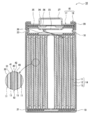
- FIG. 1 is a cross-sectional view of a nonaqueous electrolyte secondary battery 10 which is an example of an embodiment.
- the nonaqueous electrolyte secondary battery 10 includes an electrode body 14, a nonaqueous electrolyte (not shown), and a battery case 15 that houses the electrode body 14 and the nonaqueous electrolyte.
- the electrode body 14 includes a positive electrode 11, a negative electrode 12, and a separator 13, and has a winding structure in which the positive electrode 11 and the negative electrode 12 are wound via the separator 13.
- the battery case 15 includes a bottomed cylindrical outer can 16 and a sealing body 17 that closes an opening of the outer can 16.
- the non-aqueous electrolyte includes a non-aqueous solvent and an electrolyte salt dissolved in the non-aqueous solvent.
- the non-aqueous solvent for example, esters, ethers, nitriles, amides, and a mixed solvent of two or more thereof may be used.
- the non-aqueous solvent may contain a halogen-substituted product in which at least a part of hydrogen in these solvents is substituted with a halogen atom such as fluorine.
- the non-aqueous electrolyte is not limited to a liquid electrolyte, and may be a solid electrolyte using a gel polymer or the like.
- the electrolyte salt a lithium salt such as LiPF 6 is used.
- the nonaqueous electrolyte secondary battery 10 includes insulating plates 18 and 19 disposed above and below the electrode body 14, respectively.
- the positive electrode lead 20 attached to the positive electrode 11 extends to the sealing body 17 side through the through hole of the insulating plate 18, and the negative electrode lead 21 attached to the negative electrode 12 passes outside the insulating plate 19. Extending to the bottom side of the outer can 16.
- the positive electrode lead 20 is connected to the lower surface of the filter 23 which is the bottom plate of the sealing body 17 by welding or the like, and the cap 27 which is the top plate of the sealing body 17 electrically connected to the filter 23 serves as a positive electrode terminal.
- the negative electrode lead 21 is connected to the bottom inner surface of the outer can 16 by welding or the like, and the outer can 16 serves as a negative electrode terminal.
- the outer can 16 is, for example, a bottomed cylindrical metal container.
- a gasket 28 is provided between the outer can 16 and the sealing body 17 to ensure the sealing inside the battery.
- a protruding portion 22 that supports the sealing body 17 is formed in which a part of the side surface portion protrudes inward.
- the overhang portion 22 is preferably formed in an annular shape along the circumferential direction of the outer can 16, and supports the sealing body 17 on its upper surface.
- the sealing body 17 has a structure in which a filter 23, a lower valve body 24, an insulating member 25, an upper valve body 26, and a cap 27 are laminated in this order from the electrode body 14 side.
- Each member which comprises the sealing body 17 has disk shape or a ring shape, for example, and each member except the insulating member 25 is electrically connected mutually.
- the lower valve body 24 and the upper valve body 26 are connected to each other at the center, and an insulating member 25 is interposed between the peripheral edges.
- the positive electrode 11 includes a positive electrode current collector 30 and a positive electrode mixture layer 31 provided on the positive electrode current collector 30.
- a metal foil that is stable within the potential range of the positive electrode 11 such as aluminum or an aluminum alloy, a film in which the metal is disposed on the surface layer, or the like can be used.
- the positive electrode mixture layer 31 includes a positive electrode active material, a conductive material such as acetylene black, and a binder such as polyvinylidene fluoride (PVdF), and is preferably provided on both surfaces of the positive electrode current collector 30.
- PVdF polyvinylidene fluoride
- the positive electrode 11 is formed by applying a positive electrode mixture slurry containing a positive electrode active material, a conductive material, a binder, and the like on the positive electrode current collector 30, drying the coating film, and compressing the positive electrode mixture layer 31. It can be produced by forming on both surfaces of the positive electrode current collector 30.
- a lithium metal composite oxide is used as the positive electrode active material.
- metal elements contained in the lithium metal composite oxide include Ni, Co, Mn, Al, B, Mg, Ti, V, Cr, Fe, Cu, Zn, Ga, Sr, Zr, Nb, In, Sn, Ta, W, etc. are mentioned.
- An example of a suitable lithium metal composite oxide is a lithium metal composite oxide containing at least one of Ni, Co, and Mn. Specific examples include lithium metal composite oxides containing Ni, Co, and Mn, and lithium metal composite oxides containing Ni, Co, and Al. Note that inorganic particles such as tungsten oxide, aluminum oxide, and a lanthanoid-containing compound may be fixed to the surface of the lithium metal composite oxide particles.
- the negative electrode 12 includes a negative electrode current collector 40 and a negative electrode mixture layer 41 provided on the negative electrode current collector 40.
- a metal foil that is stable in the potential range of the negative electrode 12, such as copper, a film in which the metal is disposed on the surface layer, or the like can be used.
- the negative electrode mixture layer 41 includes a negative electrode active material and a binder, and is preferably provided on both surfaces of the negative electrode current collector 40.
- the negative electrode 12 is formed by applying a negative electrode mixture slurry containing a negative electrode active material and a binder on the negative electrode current collector 40, drying the coating film, and then compressing the negative electrode mixture layer 41 to form the negative electrode collector layer 41. It can be produced by forming on both surfaces of the electric body 40.
- the negative electrode mixture layer 41 has a first layer 42 and a second layer 43 formed in this order from the negative electrode current collector 40 side.
- the first layer 42 includes a first carbon-based active material (hereinafter referred to as carbon-based active material A) having a 10% proof stress of 3 MPa or less and a silicon-based active material containing Si.
- the second layer 43 includes a second carbon-based active material (hereinafter referred to as a carbon-based active material B) having a 10% proof stress of 5 MPa or more, and the content (mass ratio) of the silicon-based active material as compared with the first layer 42. ) Is low.
- the carbon-based active materials A and B are negative electrode active materials made of a carbon material, and preferably include graphite as a main component. Examples of graphite include natural graphite such as flake graphite, massive graphite, and earthy graphite, artificial graphite such as massive artificial graphite, and graphitized mesophase carbon microbeads.
- the negative electrode mixture layer 41 may have a third layer, but preferably has a two-layer structure including a first layer 42 and a second layer 43.
- the two-layer structure is preferably formed on both sides of the negative electrode current collector 40.
- the negative electrode mixture layer 41 may contain a negative electrode active material other than the carbon-based active materials A and B and the silicon-based active material as long as the object of the present disclosure is not impaired.
- Carbon-based active materials A and B having different hardnesses are added to the first layer 42 and the second layer 43, respectively.
- the carbon-based active material A of the first layer 42 is softer than the carbon-based active material B of the second layer 43.
- the content of the silicon-based active material is preferably the first layer 42> the second layer 43, and the second layer 43 preferably does not substantially contain the silicon-based active material.
- the content rate of the silicon-based active material in each layer is the ratio of the mass of the silicon-based active material contained in each layer to the total mass of each layer.
- the thickness of the negative electrode mixture layer 41 is, for example, 20 ⁇ m to 120 ⁇ m on one side of the negative electrode current collector 40.
- the thickness of the first layer 42 is preferably 30 to 80%, more preferably 50 to 70% of the thickness of the negative electrode mixture layer 41.
- the thickness of the second layer 43 is preferably 20 to 70%, more preferably 30 to 50% of the thickness of the negative electrode mixture layer 41. In this case, it is easy to achieve both high energy density and good output characteristics.
- the thickness of the second layer 43 may be thinner than the thickness of the first layer 42, for example, or may be substantially the same.
- the silicon-based active material is preferably included only in the first layer 42.
- the silicon-based active material is Si or a compound containing Si, and is preferably a silicon oxide represented by SiO x (0.5 ⁇ x ⁇ 1.6).
- the silicon oxide represented by SiO x has a structure in which Si fine particles are dispersed in an amorphous SiO 2 matrix.
- the silicon-based active material may be a compound represented by Li 2y SiO (2 + y) (0 ⁇ y ⁇ 2) in which Si fine particles are dispersed in a lithium silicate phase.
- a conductive coating composed of a material having higher conductivity than Si or a compound containing Si is formed on the particle surface of the silicon-based active material.
- the constituent material of the conductive film include at least one selected from a carbon material, a metal, and a metal compound.
- a carbon material such as amorphous carbon is preferable.
- the carbon coating can be formed by, for example, a CVD method using acetylene, methane, or the like, a method in which coal pitch, petroleum pitch, phenol resin, or the like is mixed with a silicon-based active material and heat treatment is performed.
- the conductive coating may be formed by fixing a conductive filler such as carbon black to the particle surface of the silicon-based active material using a binder.
- the content of the silicon-based active material in the first layer 42 is, for example, 4 to 20% by mass, preferably 6 to 12% by mass with respect to the total mass of the first layer 42.
- the mixing ratio of the carbon-based active material A and the silicon-based active material is, for example, 1:99 to 20:80 by mass ratio, and preferably 5:95 to 15:85. If the addition amount of the silicon-based active material is within this range, high energy density, good output characteristics, and good cycle characteristics can be easily arranged.
- the volume-based median diameter of the silicon-based active material such as silicon acid represented by SiO x (hereinafter referred to as D50) is preferably 0.5 times or less of D50 of the carbon-based active material A.
- the carbon-based active material A can easily reduce the volume change of the silicon-based active material.
- D50 of the silicon-based active material is, for example, 0.5 to 20 ⁇ m.
- the D50 of the carbon-based active materials A and B is, for example, 5 to 30 ⁇ m.
- the D50 of the silicon-based active material and the carbon-based active materials A and B is measured by, for example, a laser diffraction / scattering particle size distribution measuring apparatus (trade name “LA-920” manufactured by HORIBA).
- the carbon-based active material A is a soft particle having a 10% proof stress of 3 MPa or less.
- the carbon-based active material B is a hard particle having a 10% proof stress of 5 MPa or more.
- the carbon-based active material A relaxes the volume change of the silicon-based active material, and the carbon-based active material B improves output characteristics.
- the carbon-based active material B may be mixed in the first layer 42 and the carbon-based active material A may be mixed in the second layer 43 as long as the object of the present disclosure is not impaired.
- 10% proof stress means the pressure when the particles of the carbon-based active materials A and B are compressed by 10% in volume ratio.
- the 10% proof stress can be measured for each particle of the carbon-based active materials A and B using a micro compression tester (manufactured by Shimadzu Corporation, MCT-211). For the measurement, particles having the same particle diameter as each D50 of the carbon-based active materials A and B are used.
- the carbon-based active material A may not have voids in the particles, but the carbon-based active material B preferably has voids in the particles. Specifically, the carbon-based active material B preferably has a porosity of 1 to 5%. In this case, it becomes easy to enhance output characteristics while ensuring a hardness with a 10% yield strength of 5 MPa or more.
- the porosity of the carbon-based active material A is 2 to 10, for example.
- the porosity of the carbon-based active materials A and B can be measured by creating a cross section of the active material using an ion milling apparatus and observing with a scanning electron microscope (SEM).
- the carbon-based active material A may not substantially contain an amorphous component (amorphous carbon), but the carbon-based active material B preferably contains an amorphous component. Specifically, the carbon-based active material B preferably contains 1 to 5% by mass of an amorphous component. In this case, it becomes easy to ensure 10% yield strength of 5 MPa or more.
- the amount of the amorphous component of the carbon-based active material A is, for example, 0.1 to 2% by mass, which is smaller than the amount of the amorphous component of the carbon-based active material B.
- the amorphous component amount (amorphous carbon amount) of the carbon-based active materials A and B can be quantified by Raman spectroscopic measurement.
- the G band (G-band) peak derived from the graphite structure appears in the vicinity of 1590 cm ⁇ 1
- the D band (D-band) derived from defects in the vicinity of 1350 cm ⁇ 1.
- the peak intensity ratio of D-band / G-band can be used as an index of the amount of amorphous carbon, and the higher the ratio, the larger the amount of amorphous carbon.
- the D-band / G-band ratio can be obtained, for example, by measuring each cross section of the first layer 42 and the second layer 43 by Raman spectroscopy.
- the D-band / G-band ratio (R value) of the first layer 42 is the ratio of the carbon-based active material A ( The same applies to the carbon-based active material B of the second layer 43).
- the D-band / G-band ratio of the carbon-based active material A is preferably 0.05 to 0.2.
- the D-band / G-band ratio of the carbon-based active material B is preferably 0.1 to 2.0.
- the ratio of the D-band / G-band ratio of the Raman spectrum of the second layer 43 to the D-band / G-band ratio of the Raman spectrum of the first layer 42 is preferably 2 to 10, and preferably 4 to 6. More preferred.
- Amorphous carbon is carbon that has not developed a graphite crystal structure, and is amorphous or microcrystalline and in a turbulent structure. More specifically, it means a component having a d (002) plane spacing of 0.342 nm or more by X-ray diffraction.
- Specific examples of the amorphous carbon include hard carbon (non-graphitizable carbon), soft carbon (graphitizable carbon), carbon black, carbon fiber, activated carbon, and the like.
- Amorphous carbon is obtained, for example, by carbonizing a resin or a resin composition.
- phenol-based thermosetting resins, thermoplastic resins such as polyacrylonitrile, petroleum-based or coal-based tar, pitch, and the like can be used.
- Carbon black can be obtained, for example, by pyrolyzing a hydrocarbon as a raw material (pyrolysis method, incomplete combustion method).
- thermal decomposition method include a thermal method and an acetylene decomposition method.
- acetylene decomposition method examples include a contact method, a lamp / pine smoke method, a gas furnace method, and an oil furnace method.
- Specific examples of carbon black obtained by these production methods include acetylene black, ketjen black, thermal black, and furnace black.
- the amorphous carbon is preferably present in a state of being fixed to the surface of the graphite-based carbon.
- adherered means a state in which the material is chemically and / or physically bonded, and even if the negative electrode active material is stirred in water or an organic solvent, it is amorphous from the surface of the graphite-based carbon. It means that carbon is not liberated.
- the physical property and the fixed amount of amorphous carbon of the carbon-based active material can be adjusted by, for example, the type and amount of raw materials (petroleum or coal-based tar, pitch, etc.), the temperature of carbonization, time, and the like.
- the carbon-based active material B contained in the second layer 43 preferably has a 10% yield strength of 5 MPa or more and a porosity of 1 to 5%.
- a carbon-based active material B includes, for example, a core part having a void and a shell part arranged so as to cover the core part.
- the core part is preferably composed of graphite and amorphous carbon and has a void inside.
- the shell portion is made of amorphous carbon, and the thickness is preferably 50 nm or more.
- the weight ratio of the core part to the shell part is desirably 99: 1 to 95: 5.
- the porosity of the shell part is preferably lower than the porosity of the core part.
- the core portion has a porosity of 1 to 5% and the shell portion has a porosity of 0.01 to 1%.
- the carbon-based active material B having a shell portion with a certain thickness or more and a low porosity is improved in 10% proof stress.
- the core part is a mixture of graphite and a graphitizable binder and heated to 500 to 3000 ° C. in an inert gas atmosphere or a non-oxidizing atmosphere to pulverize, crush and classify the carbonized material.
- graphite include natural graphite and artificial graphite.
- Artificial graphite includes powders fired from coke such as needle coke and mosaic coke.
- the average particle diameter of graphite is 10 ⁇ m or less, more desirably 5 ⁇ m or less. This is because the use of graphite having a small particle diameter facilitates the generation of voids inside the particles and improves the output characteristics.
- Examples of the graphitizable binder include coal-based, petroleum-based, artificial-based pitches and tars, thermoplastic resins, thermosetting resins, and the like. Moreover, in order to form a space
- the method of mixing the graphite and the binder is not particularly limited, but mixing with an apparatus capable of applying compressive shear is preferable because the binder is more uniformly disposed and a harder powder can be formed.
- the mixing ratio is not limited, but the ratio of the residual carbon content of the binder component to graphite is preferably 1:99 to 30:70.
- the temperature at which the heat treatment is performed is not particularly limited, but is preferably 1500 ° C. or higher, and may be performed at 2500 ° C. or higher.
- the shell portion can be formed by a CVD method using acetylene, methane, or the like, a method in which coal pitch, petroleum pitch, phenol resin, or the like is mixed with the carbon material of the core portion and subjected to heat treatment.
- the carbon-based active material B can be obtained.
- a fluorine resin, a PAN, a polyimide resin, an acrylic resin, a polyolefin resin, or the like can be used for the binder contained in the negative electrode mixture layer 41, but preferably a styrene butadiene rubber. (SBR) is used.
- the negative electrode mixture layer 41 preferably further contains CMC or a salt thereof, polyacrylic acid (PAA) or a salt thereof, polyvinyl alcohol, or the like.
- the type and amount of the binder used may be changed between the first layer 42 and the second layer 43.
- the first layer 42 preferably contains PAA or a salt thereof together with SBR and CMC or a salt thereof.
- PAA or a salt thereof has strong adhesion to the silicon-based active material, and the strength of the first layer 42 can be increased by using this.
- the content of PAA or a salt thereof is preferably 0.1 to 3% by mass and more preferably 0.5 to 2% by mass with respect to the total mass of the first layer 42.
- the content of PAA or a salt thereof can be measured by microscopic Raman spectroscopy, SEM-EDX or the like.
- the separator 13 a porous sheet having ion permeability and insulating properties is used. Specific examples of the porous sheet include a microporous thin film, a woven fabric, and a nonwoven fabric.
- an olefin resin such as polyethylene or polypropylene, cellulose, or the like is preferable.
- the separator 13 may have either a single layer structure or a laminated structure. A heat resistant layer or the like may be formed on the surface of the separator 13.
- Example 1 [Production of positive electrode]
- a lithium-containing transition metal oxide represented by Li 1.0 Ni 0.5 Co 0.2 Mn 0.3 O 2 was used as the positive electrode active material.
- the positive electrode active material, acetylene black, and PVdF were mixed at a mass ratio of 94.8: 4: 1.2, and an appropriate amount of N-methyl-2-pyrrolidone was added to prepare a positive electrode mixture slurry.
- the positive electrode mixture slurry is applied to both surfaces of a positive electrode current collector made of an aluminum foil, leaving portions where leads are connected, and after drying the coating film, the coating film is rolled using a roller. It cut
- the first negative electrode mixture slurry for the first layer was prepared by mixing at a mass ratio of 1 and adding an appropriate amount of water.
- the first negative electrode mixture slurry was applied to both surfaces of a negative electrode current collector made of copper foil, leaving portions where leads were connected, and the coating film was dried to form a first layer.
- the second negative electrode mixture slurry was applied on the first layer, and the coating film was dried to form a second layer.
- the negative electrode compound material layer which rolls a coating film (1st layer and 2nd layer) using a roller, cut
- a negative electrode formed with was prepared.
- the thickness ratio of the second layer / first layer was 2.0.
- LiPF 6 was dissolved in a mixed solvent in which ethylene carbonate (EC) and ethyl methyl carbonate (EMC) were mixed at a volume ratio of 3: 7 to a concentration of 1.0 mol / liter. Furthermore, vinylene carbonate (VC) was dissolved in the above mixed solvent at a concentration of 2% by volume to prepare a nonaqueous electrolyte.
- EC ethylene carbonate
- EMC ethyl methyl carbonate
- VC vinylene carbonate
- Electrode body was accommodated in a battery exterior body composed of an aluminum laminate sheet, and after the nonaqueous electrolyte was injected, the exterior body was sealed to produce a test cell (laminate cell) having a design capacity of 640 mAh.
- the amount of the amorphous component of the carbon-based active material contained in the negative electrode mixture layer (first layer and second layer) was evaluated by Raman spectroscopic measurement.
- the peak intensity ratio (R value) of D-band / G-band in the Raman spectrum of the carbon-based active material can be used as an index of the amount of amorphous carbon as described above, and the higher the ratio, the more amorphous carbon Means a lot.
- the first layer and the second layer were subjected to Raman spectroscopic measurement to determine the D-band / G-band ratio of each layer, and the amorphous component amount was calculated from the ratio.
- the BET specific surface area of the carbon-based active material was measured using TriStar manufactured by micromeritics.
- the cycle test was performed under the following conditions, the resistance value after 200 cycles was obtained by the above method, and the increase rate of the resistance value after 200 cycles with respect to the resistance value before the cycle test was calculated.
- Example 2 Other than using carbon-based active material B, graphite having a 10% proof stress of 6.6 MPa, a porosity of 2%, an amorphous component amount of 1.5% by mass, and a BET specific surface area of 4.4 m 2 / g. Produced a negative electrode and a test cell in the same manner as in Example 1.
- Example 3 Other than using carbon-based active material B, graphite having a 10% proof stress of 27 MPa, a porosity of 3.1%, an amorphous component amount of 4.0% by mass, and a BET specific surface area of 3.0 m 2 / g. Produced a negative electrode and a test cell in the same manner as in Example 1.
- Carbon-based active material B graphite having a 10% proof stress of 2.1 MPa, a porosity of 4.2%, an amorphous component amount of 0.6% by mass, and a BET specific surface area of 4.0 m 2 / g is used.
Landscapes
- Chemical & Material Sciences (AREA)
- Chemical Kinetics & Catalysis (AREA)
- Electrochemistry (AREA)
- General Chemical & Material Sciences (AREA)
- Composite Materials (AREA)
- Engineering & Computer Science (AREA)
- Materials Engineering (AREA)
- Inorganic Chemistry (AREA)
- Manufacturing & Machinery (AREA)
- Battery Electrode And Active Subsutance (AREA)
Abstract
L'invention concerne une batterie secondaire à électrolyte non aqueux dans laquelle, une couche de mélange d'électrodes négatives comporte une première couche et une seconde couche formées dans cet ordre à partir du côté d'un collecteur de courant d'électrode négative. La première couche comprend un premier matériau actif à base de carbone ayant une limite d'élasticité à 10 % inférieure ou égale à 3 MPa, et un matériau actif à base de silicium contenant du Si. La seconde couche contient un second matériau actif à base de carbone ayant une limite d'élasticité à 10 % supérieure ou égale à 5 MPa, et a un rapport de contenu (rapport de masse) du matériau actif à base de silicium inférieur à celui de la première couche.
Priority Applications (4)
| Application Number | Priority Date | Filing Date | Title |
|---|---|---|---|
| CN201980004965.9A CN111344884B (zh) | 2018-03-30 | 2019-01-22 | 非水电解质二次电池用负极和非水电解质二次电池 |
| EP19775915.2A EP3780169A4 (fr) | 2018-03-30 | 2019-01-22 | Électrode négative pour batterie secondaire à électrolyte non aqueux et batterie secondaire à électrolyte non aqueux |
| US16/982,284 US11909033B2 (en) | 2018-03-30 | 2019-01-22 | Negative electrode including first layer having low compressive strength carbon active material and silicon active material and second layer having high compressive strength carbon active material and nonaqueous electrolyte secondary battery including the same |
| JP2020509711A JP7161523B2 (ja) | 2018-03-30 | 2019-01-22 | 非水電解質二次電池用負極及び非水電解質二次電池 |
Applications Claiming Priority (2)
| Application Number | Priority Date | Filing Date | Title |
|---|---|---|---|
| JP2018068723 | 2018-03-30 | ||
| JP2018-068723 | 2018-03-30 |
Publications (1)
| Publication Number | Publication Date |
|---|---|
| WO2019187537A1 true WO2019187537A1 (fr) | 2019-10-03 |
Family
ID=68058118
Family Applications (1)
| Application Number | Title | Priority Date | Filing Date |
|---|---|---|---|
| PCT/JP2019/001801 WO2019187537A1 (fr) | 2018-03-30 | 2019-01-22 | Électrode négative pour batterie secondaire à électrolyte non aqueux et batterie secondaire à électrolyte non aqueux |
Country Status (5)
| Country | Link |
|---|---|
| US (1) | US11909033B2 (fr) |
| EP (1) | EP3780169A4 (fr) |
| JP (1) | JP7161523B2 (fr) |
| CN (1) | CN111344884B (fr) |
| WO (1) | WO2019187537A1 (fr) |
Cited By (20)
| Publication number | Priority date | Publication date | Assignee | Title |
|---|---|---|---|---|
| CN112825351A (zh) * | 2019-11-20 | 2021-05-21 | 丰田自动车株式会社 | 全固体电池 |
| WO2021111930A1 (fr) * | 2019-12-06 | 2021-06-10 | 三洋電機株式会社 | Accumulateur à électrolyte non aqueux |
| WO2021111932A1 (fr) * | 2019-12-06 | 2021-06-10 | 三洋電機株式会社 | Batterie secondaire à électrolyte non aqueux |
| WO2021111931A1 (fr) * | 2019-12-06 | 2021-06-10 | 三洋電機株式会社 | Batterie secondaire à électrolyte non aqueux |
| WO2021117480A1 (fr) * | 2019-12-09 | 2021-06-17 | 三洋電機株式会社 | Batterie secondaire à électrolyte non aqueux |
| CN113258033A (zh) * | 2020-02-12 | 2021-08-13 | 松下电器产业株式会社 | 非水电解质二次电池和二次电池组件 |
| EP3869584A1 (fr) * | 2020-02-18 | 2021-08-25 | Samsung Electronics Co., Ltd. | Batterie secondaire entièrement solide et procédé de fabrication de batterie secondaire entièrement solide |
| CN113410431A (zh) * | 2020-03-17 | 2021-09-17 | 松下电器产业株式会社 | 非水电解质二次电池和二次电池组件 |
| CN113410430A (zh) * | 2020-03-17 | 2021-09-17 | 松下电器产业株式会社 | 非水电解质二次电池和二次电池组件 |
| JP2022008268A (ja) * | 2020-06-26 | 2022-01-13 | 三星エスディアイ株式会社 | リチウム二次電池用負極およびこれを含むリチウム二次電池 |
| US11721802B2 (en) | 2019-12-26 | 2023-08-08 | Panasonic Holdings Corporation | Negative electrode for nonaqueous electrolyte secondary battery, and nonaqueous electrolyte secondary battery |
| US11728471B2 (en) | 2019-12-23 | 2023-08-15 | Panasonic Holdings Corporation | Negative electrode for nonaqueous electrolyte secondary battery, and nonaqueous electrolyte secondary battery |
| US11728472B2 (en) | 2019-12-23 | 2023-08-15 | Panasonic Holdings Corporation | Negative electrode for nonaqueous electrolyte secondary battery, and nonaqueous electrolyte secondary battery |
| WO2023157746A1 (fr) * | 2022-02-15 | 2023-08-24 | パナソニックエナジ-株式会社 | Batterie secondaire à électrolyte non aqueux |
| US11742548B2 (en) | 2020-01-16 | 2023-08-29 | Panasonic Holdings Corporation | Electrical storage device and electrical storage module |
| JP7349349B2 (ja) | 2019-12-26 | 2023-09-22 | パナソニックホールディングス株式会社 | 非水電解質二次電池用負極、及び非水電解質二次電池 |
| US11811050B2 (en) | 2020-02-12 | 2023-11-07 | Panasonic Holdings Corporation | Nonaqueous-electrolyte secondary battery and secondary battery module |
| WO2024024505A1 (fr) * | 2022-07-29 | 2024-02-01 | パナソニックエナジー株式会社 | Électrode négative pour batteries secondaires à électrolyte non aqueux, et batterie secondaire à électrolyte non aqueux |
| EP4075541A4 (fr) * | 2019-12-13 | 2024-03-13 | Panasonic Ip Man Co Ltd | Batterie secondaire à électrolyte non aqueux |
| CN113258033B (zh) * | 2020-02-12 | 2024-06-04 | 松下控股株式会社 | 非水电解质二次电池和二次电池组件 |
Families Citing this family (5)
| Publication number | Priority date | Publication date | Assignee | Title |
|---|---|---|---|---|
| CN111628141B (zh) * | 2020-07-16 | 2021-05-25 | 珠海冠宇电池股份有限公司 | 一种掺硅负极极片及包括该负极极片的锂离子电池 |
| CN114079048A (zh) * | 2020-08-18 | 2022-02-22 | 比亚迪股份有限公司 | 一种负极极片以及锂离子电池 |
| JP7337109B2 (ja) * | 2021-02-16 | 2023-09-01 | プライムプラネットエナジー&ソリューションズ株式会社 | 負極板、非水電解質二次電池、および負極板の製造方法 |
| CN113839009B (zh) * | 2021-08-23 | 2023-01-31 | 惠州锂威新能源科技有限公司 | 一种负极浆料及其制备方法、负极片以及二次电池 |
| KR20240014878A (ko) * | 2022-07-26 | 2024-02-02 | 에스케이온 주식회사 | 리튬 이차 전지용 음극 및 이를 포함하는 리튬 이차 전지 |
Citations (4)
| Publication number | Priority date | Publication date | Assignee | Title |
|---|---|---|---|---|
| JPS6211595B2 (fr) | 1984-05-24 | 1987-03-13 | Mitsubishi Kakoki Kk | |
| JP2000268824A (ja) * | 1999-01-14 | 2000-09-29 | Hitachi Ltd | リチウム電池及びその製造方法 |
| JP2015038862A (ja) * | 2013-07-18 | 2015-02-26 | 三菱化学株式会社 | 非水系二次電池負極用炭素材、それを用いた非水系二次電池用負極及び非水系二次電池 |
| JP2015049965A (ja) * | 2013-08-30 | 2015-03-16 | 三菱自動車工業株式会社 | 二次電池用の電極 |
Family Cites Families (14)
| Publication number | Priority date | Publication date | Assignee | Title |
|---|---|---|---|---|
| US5677082A (en) * | 1996-05-29 | 1997-10-14 | Ucar Carbon Technology Corporation | Compacted carbon for electrochemical cells |
| EP1020944B1 (fr) | 1999-01-14 | 2011-12-07 | Hitachi Chemical Company, Ltd. | Pile secondaire au lithium et son procédé de fabrication |
| JP4400019B2 (ja) * | 2002-04-10 | 2010-01-20 | 日本電気株式会社 | 非水電解液電池及びその生成方法 |
| JP4824394B2 (ja) * | 2004-12-16 | 2011-11-30 | パナソニック株式会社 | リチウムイオン二次電池用負極、その製造方法、およびそれを用いたリチウムイオン二次電池 |
| JP2009004139A (ja) * | 2007-06-20 | 2009-01-08 | Hitachi Maxell Ltd | リチウム二次電池 |
| JP5481904B2 (ja) * | 2009-03-30 | 2014-04-23 | 日産自動車株式会社 | リチウムイオン二次電池用負極およびこれを用いたリチウムイオン二次電池 |
| JP5666378B2 (ja) * | 2010-05-24 | 2015-02-12 | 信越化学工業株式会社 | 非水電解質二次電池用負極活物質の製造方法及び非水電解質二次電池用負極活物質並びに非水電解質二次電池用負極材、非水電解質二次電池用負極、非水電解質二次電池 |
| WO2014007161A1 (fr) | 2012-07-06 | 2014-01-09 | 東レ株式会社 | Matériau d'électrode négative pour batteries secondaires à ion lithium, matériau d'électrode négative composite pour batteries secondaires à ion lithium, composition de résine pour électrodes négatives de batteries secondaires à ion lithium, électrode négative de batteries secondaires à ion lithium, et batterie secondaire à ion lithium |
| CN104904045A (zh) | 2012-09-19 | 2015-09-09 | 三菱化学株式会社 | 非水系二次电池负极用复合石墨粒子、非水系二次电池用负极及非水系二次电池 |
| JP6211595B2 (ja) | 2013-03-29 | 2017-10-11 | 三洋電機株式会社 | 非水電解質二次電池 |
| CN106030864B (zh) * | 2014-01-31 | 2019-05-28 | 三洋电机株式会社 | 非水电解质二次电池用负极 |
| WO2016035289A1 (fr) * | 2014-09-05 | 2016-03-10 | 三洋電機株式会社 | Electrode négative pour batteries secondaires à électrolyte non aqueux et batterie secondaire à électrolyte non aqueux |
| US20200006761A1 (en) | 2016-06-30 | 2020-01-02 | Ube Industries, Ltd. | Lithium titanate powder for electrode of energy storage device, active material, and electrode sheet and energy storage device using the same |
| KR101986626B1 (ko) * | 2016-08-26 | 2019-09-30 | 주식회사 엘지화학 | 리튬 이차전지용 음극 및 이를 포함하는 리튬 이차전지 |
-
2019
- 2019-01-22 WO PCT/JP2019/001801 patent/WO2019187537A1/fr active Application Filing
- 2019-01-22 JP JP2020509711A patent/JP7161523B2/ja active Active
- 2019-01-22 CN CN201980004965.9A patent/CN111344884B/zh active Active
- 2019-01-22 US US16/982,284 patent/US11909033B2/en active Active
- 2019-01-22 EP EP19775915.2A patent/EP3780169A4/fr active Pending
Patent Citations (4)
| Publication number | Priority date | Publication date | Assignee | Title |
|---|---|---|---|---|
| JPS6211595B2 (fr) | 1984-05-24 | 1987-03-13 | Mitsubishi Kakoki Kk | |
| JP2000268824A (ja) * | 1999-01-14 | 2000-09-29 | Hitachi Ltd | リチウム電池及びその製造方法 |
| JP2015038862A (ja) * | 2013-07-18 | 2015-02-26 | 三菱化学株式会社 | 非水系二次電池負極用炭素材、それを用いた非水系二次電池用負極及び非水系二次電池 |
| JP2015049965A (ja) * | 2013-08-30 | 2015-03-16 | 三菱自動車工業株式会社 | 二次電池用の電極 |
Cited By (30)
| Publication number | Priority date | Publication date | Assignee | Title |
|---|---|---|---|---|
| CN112825351A (zh) * | 2019-11-20 | 2021-05-21 | 丰田自动车株式会社 | 全固体电池 |
| WO2021111930A1 (fr) * | 2019-12-06 | 2021-06-10 | 三洋電機株式会社 | Accumulateur à électrolyte non aqueux |
| WO2021111932A1 (fr) * | 2019-12-06 | 2021-06-10 | 三洋電機株式会社 | Batterie secondaire à électrolyte non aqueux |
| WO2021111931A1 (fr) * | 2019-12-06 | 2021-06-10 | 三洋電機株式会社 | Batterie secondaire à électrolyte non aqueux |
| EP4071847A4 (fr) * | 2019-12-06 | 2024-01-03 | Sanyo Electric Co | Accumulateur à électrolyte non aqueux |
| CN114788048A (zh) * | 2019-12-06 | 2022-07-22 | 三洋电机株式会社 | 非水电解液二次电池 |
| WO2021117480A1 (fr) * | 2019-12-09 | 2021-06-17 | 三洋電機株式会社 | Batterie secondaire à électrolyte non aqueux |
| EP4075541A4 (fr) * | 2019-12-13 | 2024-03-13 | Panasonic Ip Man Co Ltd | Batterie secondaire à électrolyte non aqueux |
| US11728471B2 (en) | 2019-12-23 | 2023-08-15 | Panasonic Holdings Corporation | Negative electrode for nonaqueous electrolyte secondary battery, and nonaqueous electrolyte secondary battery |
| JP7349347B2 (ja) | 2019-12-23 | 2023-09-22 | パナソニックホールディングス株式会社 | 非水電解質二次電池用負極、及び非水電解質二次電池 |
| US11728472B2 (en) | 2019-12-23 | 2023-08-15 | Panasonic Holdings Corporation | Negative electrode for nonaqueous electrolyte secondary battery, and nonaqueous electrolyte secondary battery |
| JP7372146B2 (ja) | 2019-12-26 | 2023-10-31 | パナソニックホールディングス株式会社 | 非水電解質二次電池用負極、及び非水電解質二次電池 |
| US11721802B2 (en) | 2019-12-26 | 2023-08-08 | Panasonic Holdings Corporation | Negative electrode for nonaqueous electrolyte secondary battery, and nonaqueous electrolyte secondary battery |
| JP7349349B2 (ja) | 2019-12-26 | 2023-09-22 | パナソニックホールディングス株式会社 | 非水電解質二次電池用負極、及び非水電解質二次電池 |
| US11742548B2 (en) | 2020-01-16 | 2023-08-29 | Panasonic Holdings Corporation | Electrical storage device and electrical storage module |
| US11791471B2 (en) | 2020-02-12 | 2023-10-17 | Panasonic Holdings Corporation | Nonaqueous-electrolyte secondary battery and secondary battery module |
| US11811050B2 (en) | 2020-02-12 | 2023-11-07 | Panasonic Holdings Corporation | Nonaqueous-electrolyte secondary battery and secondary battery module |
| CN113258033B (zh) * | 2020-02-12 | 2024-06-04 | 松下控股株式会社 | 非水电解质二次电池和二次电池组件 |
| CN113258033A (zh) * | 2020-02-12 | 2021-08-13 | 松下电器产业株式会社 | 非水电解质二次电池和二次电池组件 |
| JP7403337B2 (ja) | 2020-02-12 | 2023-12-22 | パナソニックホールディングス株式会社 | 非水電解質二次電池及び二次電池モジュール |
| US11777076B2 (en) | 2020-02-18 | 2023-10-03 | Samsung Electronics Co., Ltd. | All-solid secondary battery, and method of manufacturing all-solid secondary battery |
| EP3869584A1 (fr) * | 2020-02-18 | 2021-08-25 | Samsung Electronics Co., Ltd. | Batterie secondaire entièrement solide et procédé de fabrication de batterie secondaire entièrement solide |
| CN113410431A (zh) * | 2020-03-17 | 2021-09-17 | 松下电器产业株式会社 | 非水电解质二次电池和二次电池组件 |
| US11557787B2 (en) | 2020-03-17 | 2023-01-17 | Panasonic Holdings Corporation | Nonaqueous electrolyte secondary battery and secondary battery module |
| US11817577B2 (en) | 2020-03-17 | 2023-11-14 | Panasonic Holdings Corporation | Nonaqueous electrolyte secondary battery and secondary battery module |
| JP7432410B2 (ja) | 2020-03-17 | 2024-02-16 | パナソニックホールディングス株式会社 | 非水電解質二次電池及び二次電池モジュール |
| CN113410430A (zh) * | 2020-03-17 | 2021-09-17 | 松下电器产业株式会社 | 非水电解质二次电池和二次电池组件 |
| JP2022008268A (ja) * | 2020-06-26 | 2022-01-13 | 三星エスディアイ株式会社 | リチウム二次電池用負極およびこれを含むリチウム二次電池 |
| WO2023157746A1 (fr) * | 2022-02-15 | 2023-08-24 | パナソニックエナジ-株式会社 | Batterie secondaire à électrolyte non aqueux |
| WO2024024505A1 (fr) * | 2022-07-29 | 2024-02-01 | パナソニックエナジー株式会社 | Électrode négative pour batteries secondaires à électrolyte non aqueux, et batterie secondaire à électrolyte non aqueux |
Also Published As
| Publication number | Publication date |
|---|---|
| JPWO2019187537A1 (ja) | 2021-03-25 |
| US11909033B2 (en) | 2024-02-20 |
| US20210013496A1 (en) | 2021-01-14 |
| CN111344884B (zh) | 2023-09-29 |
| EP3780169A1 (fr) | 2021-02-17 |
| EP3780169A4 (fr) | 2021-06-02 |
| JP7161523B2 (ja) | 2022-10-26 |
| CN111344884A (zh) | 2020-06-26 |
Similar Documents
| Publication | Publication Date | Title |
|---|---|---|
| JP7161523B2 (ja) | 非水電解質二次電池用負極及び非水電解質二次電池 | |
| KR101633206B1 (ko) | 리튬 이온 이차 전지용 부극 재료, 리튬 이온 이차 전지용 부극 및 리튬 이온 이차 전지 | |
| WO2016136180A1 (fr) | Matériau actif d'électrode négative pour pile rechargeable à électrolyte non aqueux, électrode négative pour pile rechargeable à électrolyte non aqueux, et pile rechargeable à électrolyte non aqueux | |
| WO2018225515A1 (fr) | Électrode négative pour batteries secondaires à électrolyte non aqueux, et batterie secondaire à électrolyte non aqueux | |
| CN114430864A (zh) | 锂离子二次电池用负极和锂离子二次电池 | |
| WO2020066576A1 (fr) | Électrode négative de batterie secondaire à électrolyte non aqueux, et batterie secondaire à électrolyte non aqueux | |
| JP2019067579A (ja) | リチウムイオン二次電池及びリチウムイオン二次電池用負極材料 | |
| JP2012216521A (ja) | 非水電解質二次電池用負極材の製造方法、及びその製造方法で得られた負極材、負極並びに非水電解質二次電池 | |
| JP7126840B2 (ja) | 非水電解質二次電池用負極及び非水電解質二次電池 | |
| JP2009187939A (ja) | リチウムイオン二次電池用負極材料およびその製造方法、リチウムイオン二次電池用負極ならびにリチウムイオン二次電池 | |
| JP2011138680A (ja) | 非水電解質二次電池用負極および非水電解質二次電池 | |
| JP4542352B2 (ja) | リチウムイオン二次電池用負極、およびリチウムイオン二次電池 | |
| US20220246923A1 (en) | Negative electrode active material for secondary batteries, and secondary battery | |
| JP7474951B2 (ja) | 二次電池用の負極活物質、及び二次電池 | |
| JP5133543B2 (ja) | メソカーボン小球体黒鉛化物の製造方法 | |
| JP7349349B2 (ja) | 非水電解質二次電池用負極、及び非水電解質二次電池 | |
| WO2022158381A1 (fr) | Particule composite de matériau actif d'électrode négative, procédé de fabrication de particule composite de matériau actif d'électrode négative, et batterie secondaire à électrolyte non aqueux | |
| WO2023162716A1 (fr) | Matériau actif d'électrode négative pour batteries secondaires à électrolyte non aqueux, et batterie secondaire à électrolyte non aqueux | |
| WO2023162689A1 (fr) | Matériau actif d'électrode négative pour batterie secondaire à électrolyte non aqueux et batterie secondaire à électrolyte non aqueux | |
| WO2024116814A1 (fr) | Matériau actif d'électrode négative pour batteries secondaires à électrolyte non aqueux, et batterie secondaire à électrolyte non aqueux | |
| WO2024116847A1 (fr) | Matériau actif d'électrode négative pour batteries rechargeables à électrolyte non aqueux, et batterie rechargeable à électrolyte non aqueux | |
| JP7432410B2 (ja) | 非水電解質二次電池及び二次電池モジュール | |
| WO2023145603A1 (fr) | Électrode négative pour batterie secondaire à électrolyte non aqueux et batterie secondaire à électrolyte non aqueux | |
| WO2023189467A1 (fr) | Matériau actif d'électrode négative pour batteries secondaires à électrolyte non aqueux, et batterie secondaire à électrolyte non aqueux | |
| JP7372146B2 (ja) | 非水電解質二次電池用負極、及び非水電解質二次電池 |
Legal Events
| Date | Code | Title | Description |
|---|---|---|---|
| 121 | Ep: the epo has been informed by wipo that ep was designated in this application |
Ref document number: 19775915 Country of ref document: EP Kind code of ref document: A1 |
|
| ENP | Entry into the national phase |
Ref document number: 2020509711 Country of ref document: JP Kind code of ref document: A |
|
| WWE | Wipo information: entry into national phase |
Ref document number: 2019775915 Country of ref document: EP |