WO2019186811A1 - フラックス入りワイヤの製造方法、フラックス入りワイヤ、及び溶接継手の製造方法 - Google Patents
フラックス入りワイヤの製造方法、フラックス入りワイヤ、及び溶接継手の製造方法 Download PDFInfo
- Publication number
- WO2019186811A1 WO2019186811A1 PCT/JP2018/012912 JP2018012912W WO2019186811A1 WO 2019186811 A1 WO2019186811 A1 WO 2019186811A1 JP 2018012912 W JP2018012912 W JP 2018012912W WO 2019186811 A1 WO2019186811 A1 WO 2019186811A1
- Authority
- WO
- WIPO (PCT)
- Prior art keywords
- flux
- content
- cored wire
- wire
- oxide
- Prior art date
Links
Images

Classifications
-
- B—PERFORMING OPERATIONS; TRANSPORTING
- B23—MACHINE TOOLS; METAL-WORKING NOT OTHERWISE PROVIDED FOR
- B23K—SOLDERING OR UNSOLDERING; WELDING; CLADDING OR PLATING BY SOLDERING OR WELDING; CUTTING BY APPLYING HEAT LOCALLY, e.g. FLAME CUTTING; WORKING BY LASER BEAM
- B23K35/00—Rods, electrodes, materials, or media, for use in soldering, welding, or cutting
- B23K35/22—Rods, electrodes, materials, or media, for use in soldering, welding, or cutting characterised by the composition or nature of the material
- B23K35/24—Selection of soldering or welding materials proper
- B23K35/30—Selection of soldering or welding materials proper with the principal constituent melting at less than 1550 degrees C
- B23K35/3053—Fe as the principal constituent
-
- B—PERFORMING OPERATIONS; TRANSPORTING
- B23—MACHINE TOOLS; METAL-WORKING NOT OTHERWISE PROVIDED FOR
- B23K—SOLDERING OR UNSOLDERING; WELDING; CLADDING OR PLATING BY SOLDERING OR WELDING; CUTTING BY APPLYING HEAT LOCALLY, e.g. FLAME CUTTING; WORKING BY LASER BEAM
- B23K35/00—Rods, electrodes, materials, or media, for use in soldering, welding, or cutting
- B23K35/02—Rods, electrodes, materials, or media, for use in soldering, welding, or cutting characterised by mechanical features, e.g. shape
- B23K35/0255—Rods, electrodes, materials, or media, for use in soldering, welding, or cutting characterised by mechanical features, e.g. shape for use in welding
- B23K35/0261—Rods, electrodes, wires
- B23K35/0266—Rods, electrodes, wires flux-cored
-
- B—PERFORMING OPERATIONS; TRANSPORTING
- B23—MACHINE TOOLS; METAL-WORKING NOT OTHERWISE PROVIDED FOR
- B23K—SOLDERING OR UNSOLDERING; WELDING; CLADDING OR PLATING BY SOLDERING OR WELDING; CUTTING BY APPLYING HEAT LOCALLY, e.g. FLAME CUTTING; WORKING BY LASER BEAM
- B23K35/00—Rods, electrodes, materials, or media, for use in soldering, welding, or cutting
- B23K35/22—Rods, electrodes, materials, or media, for use in soldering, welding, or cutting characterised by the composition or nature of the material
- B23K35/24—Selection of soldering or welding materials proper
- B23K35/30—Selection of soldering or welding materials proper with the principal constituent melting at less than 1550 degrees C
- B23K35/3053—Fe as the principal constituent
- B23K35/3073—Fe as the principal constituent with Mn as next major constituent
-
- B—PERFORMING OPERATIONS; TRANSPORTING
- B23—MACHINE TOOLS; METAL-WORKING NOT OTHERWISE PROVIDED FOR
- B23K—SOLDERING OR UNSOLDERING; WELDING; CLADDING OR PLATING BY SOLDERING OR WELDING; CUTTING BY APPLYING HEAT LOCALLY, e.g. FLAME CUTTING; WORKING BY LASER BEAM
- B23K35/00—Rods, electrodes, materials, or media, for use in soldering, welding, or cutting
- B23K35/22—Rods, electrodes, materials, or media, for use in soldering, welding, or cutting characterised by the composition or nature of the material
- B23K35/36—Selection of non-metallic compositions, e.g. coatings, fluxes; Selection of soldering or welding materials, conjoint with selection of non-metallic compositions, both selections being of interest
- B23K35/3601—Selection of non-metallic compositions, e.g. coatings, fluxes; Selection of soldering or welding materials, conjoint with selection of non-metallic compositions, both selections being of interest with inorganic compounds as principal constituents
- B23K35/3606—Borates or B-oxides
-
- B—PERFORMING OPERATIONS; TRANSPORTING
- B23—MACHINE TOOLS; METAL-WORKING NOT OTHERWISE PROVIDED FOR
- B23K—SOLDERING OR UNSOLDERING; WELDING; CLADDING OR PLATING BY SOLDERING OR WELDING; CUTTING BY APPLYING HEAT LOCALLY, e.g. FLAME CUTTING; WORKING BY LASER BEAM
- B23K35/00—Rods, electrodes, materials, or media, for use in soldering, welding, or cutting
- B23K35/22—Rods, electrodes, materials, or media, for use in soldering, welding, or cutting characterised by the composition or nature of the material
- B23K35/36—Selection of non-metallic compositions, e.g. coatings, fluxes; Selection of soldering or welding materials, conjoint with selection of non-metallic compositions, both selections being of interest
- B23K35/368—Selection of non-metallic compositions of core materials either alone or conjoint with selection of soldering or welding materials
-
- B—PERFORMING OPERATIONS; TRANSPORTING
- B23—MACHINE TOOLS; METAL-WORKING NOT OTHERWISE PROVIDED FOR
- B23K—SOLDERING OR UNSOLDERING; WELDING; CLADDING OR PLATING BY SOLDERING OR WELDING; CUTTING BY APPLYING HEAT LOCALLY, e.g. FLAME CUTTING; WORKING BY LASER BEAM
- B23K35/00—Rods, electrodes, materials, or media, for use in soldering, welding, or cutting
- B23K35/40—Making wire or rods for soldering or welding
- B23K35/406—Filled tubular wire or rods
-
- C—CHEMISTRY; METALLURGY
- C21—METALLURGY OF IRON
- C21D—MODIFYING THE PHYSICAL STRUCTURE OF FERROUS METALS; GENERAL DEVICES FOR HEAT TREATMENT OF FERROUS OR NON-FERROUS METALS OR ALLOYS; MAKING METAL MALLEABLE, e.g. BY DECARBURISATION OR TEMPERING
- C21D9/00—Heat treatment, e.g. annealing, hardening, quenching or tempering, adapted for particular articles; Furnaces therefor
- C21D9/50—Heat treatment, e.g. annealing, hardening, quenching or tempering, adapted for particular articles; Furnaces therefor for welded joints
-
- C—CHEMISTRY; METALLURGY
- C22—METALLURGY; FERROUS OR NON-FERROUS ALLOYS; TREATMENT OF ALLOYS OR NON-FERROUS METALS
- C22C—ALLOYS
- C22C38/00—Ferrous alloys, e.g. steel alloys
- C22C38/04—Ferrous alloys, e.g. steel alloys containing manganese
-
- C—CHEMISTRY; METALLURGY
- C22—METALLURGY; FERROUS OR NON-FERROUS ALLOYS; TREATMENT OF ALLOYS OR NON-FERROUS METALS
- C22C—ALLOYS
- C22C38/00—Ferrous alloys, e.g. steel alloys
- C22C38/12—Ferrous alloys, e.g. steel alloys containing tungsten, tantalum, molybdenum, vanadium, or niobium
-
- C—CHEMISTRY; METALLURGY
- C22—METALLURGY; FERROUS OR NON-FERROUS ALLOYS; TREATMENT OF ALLOYS OR NON-FERROUS METALS
- C22C—ALLOYS
- C22C38/00—Ferrous alloys, e.g. steel alloys
- C22C38/18—Ferrous alloys, e.g. steel alloys containing chromium
- C22C38/40—Ferrous alloys, e.g. steel alloys containing chromium with nickel
- C22C38/58—Ferrous alloys, e.g. steel alloys containing chromium with nickel with more than 1.5% by weight of manganese
-
- C—CHEMISTRY; METALLURGY
- C22—METALLURGY; FERROUS OR NON-FERROUS ALLOYS; TREATMENT OF ALLOYS OR NON-FERROUS METALS
- C22C—ALLOYS
- C22C38/00—Ferrous alloys, e.g. steel alloys
Definitions
- the present invention relates to a flux cored wire manufacturing method, a flux cored wire, and a welded joint manufacturing method.
- a weather-resistant steel material that has been exposed to an atmospheric corrosive environment after being used for a long time generally has a protective rust layer formed on its surface. Since the rust layer shields the corrosion-resistant steel material from corrosive substances from the outside, the corrosion of the weather-resistant steel material after the formation of the rust layer is suppressed, and the weather resistance is exhibited. Therefore, weathering steel is used for structures such as bridges as steel that can be used as it is without being painted.
- the coating film is damaged by the coating film deterioration, and the steel material directly under the coating film scratched part is directly exposed to the corrosive environment. It shows the corrosion form in which the coating swells like a bump. Since the scratches on the coating film further progressively expand due to the progress of the corrosion form, the corrosion of the structure continues to progress. Therefore, in an environment where the amount of incoming salt is large, it is about 10 for the purpose of extending the life of the structure. Repainting is often performed on painted steel every year. Since such a repair process takes a lot of man-hours, several technical proposals have been made for corrosion-resistant steel materials that can reduce the maintenance cost by extending the coating life and greatly extending the repair coating interval. .
- Patent Document 1 Japanese Patent Application Laid-Open No. 2008-163374 discloses a weather resistance and a maintenance material that can be used as a minimum maintenance material even in an environment where the amount of incoming salt is large in a beach area, an area where snow melting salt is spread, or the like. Steel materials for bridges having excellent paint peeling resistance are disclosed.
- Patent Document 2 Japanese Patent Application Laid-Open No. 2007-262555 discloses that even in a corrosive environment in which the coating film is easily damaged mechanically and is easily affected by both SO 4 2 ⁇ and Cl ⁇ .
- a corrosion-resistant steel material for holding a coal / ore carrier that can extend the life and suppress corrosion after the coating film is peeled is disclosed.
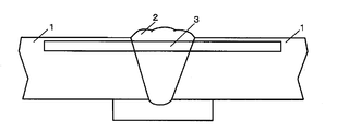
- the surplus is the outermost layer of the weld metal, and the coating applied to the area of the surplus is different from the surface of the coating applied to the surrounding smooth base material during use of the welded joint. It is more susceptible to collisions with objects and mechanical friction relatively frequently. Further, since the surplus itself is convex and has a complicated shape, the thickness of the surplus coating film tends to be thinner than the thickness of the coating film of the surrounding base material in the coating construction. For these reasons, the surfacing surface tends to cause peeling of the coating film, and thus tends to be the starting point of the corrosion form in which progressive coating destruction proceeds early from the start of use of the steel structure.
- Patent Document 3 Japanese Patent Laid-Open No. 2013-151001 discloses that welding workability in all positions is good when welding weathering steel.
- a flux-cored wire for gas shielded arc welding for weathering steel that provides a weld metal having excellent strength and toughness.
- Patent Document 4 Japanese Patent Application Laid-Open No. 2000-287881 is suitable for welding of Cu—Ni-based beach weathering steel, can be welded in all positions, has good welding workability, and has a base metal corrosion resistance.
- a flux-cored wire for gas shielded arc welding that imparts corrosion resistance to flying sea salt particles to a weld metal without loss is disclosed.
- the coating film is likely to be peeled off, and in an environment with a large amount of incoming salt, this peeling part is the starting point of the corrosion form.
- the thickness of the coating applied to the surplus, the outermost layer of the welded joint is the thickness of the coating applied to the surrounding flat base material due to the complex shape of the surplus convex This is because it tends to be thinner than the above.
- Japanese Unexamined Patent Publication No. 2008-163374 Japanese Unexamined Patent Publication No. 2007-262555 Japanese Unexamined Patent Publication No. 2013-151001 Japanese Unexamined Patent Publication No. 2000-288781
- the present invention is a weld metal that is excellent in weather resistance and paint peeling resistance in an environment where a lot of corrosive substances are present due to a large amount of incoming salt, and also excellent in mechanical properties. It is an object of the present invention to provide a method for manufacturing a flux-cored wire, a flux-cored wire, and a method for manufacturing a welded joint, in which welding workability is good in all-position welding.
- a method of manufacturing a flux-cored wire in which a flux is filled inside a steel outer shell according to an aspect of the present invention includes a step of filling a flux inside the steel sheet while forming the steel sheet into a cylindrical shape, A step of joining both ends of the steel plate to form a steel pipe, and a step of rolling and annealing the steel pipe to obtain the flux-cored wire, wherein the chemical composition of the flux-cored wire % By mass relative to the total mass, C: 0.03 to 0.12%, Si: 0.20 to 0.85%, Mn: 1.50 to 3.20%, P: 0.020% or less, S: 0.020% or less, Mg: 0.05 to 0.70%, Sn: 0.05 to 0.40%, Ti oxide: 4.60 to 7.00% in terms of TiO 2 , Si oxide: 0.20 to 0.90% in terms of SiO 2 values, Zr Compound: 0.10 to .70 percent in terms of ZrO 2 value, Cu: 0
- the element symbol in the formula 1 indicates the content of the element related to each element symbol in mass% with respect to the total mass of the flux-cored wire.
- the chemical composition of the flux-cored wire is expressed by mass% with respect to the total mass of the flux-cored wire, and W: 0 to 0.010%. Mo: 0 to 0.04% may be sufficient.
- the chemical composition of the flux-cored wire is Cu: 0.05 to 0.05% by mass with respect to the total mass of the flux-cored wire. It may be 0.70%.
- the chemical composition of the flux-cored wire is at least% by mass with respect to the total mass of the flux-cored wire. Any one of the following may be satisfied.
- the joining may be caulking.
- the joining may be welding.
- a flux cored wire according to another aspect of the present invention is manufactured by the flux cored wire manufacturing method according to any one of (1) to (6) above.
- a method for manufacturing a welded joint according to another aspect of the present invention uses a flux-cored wire manufactured by the flux-cored wire manufacturing method according to any one of (1) to (6) above. A step of welding.
- the flux-cored wire obtained by the production method of the present invention and the production method of a welded joint using the same a weld metal having excellent weather resistance and paint peeling resistance is obtained even in an environment with a large amount of incoming salt such as a beach area. Therefore, it is possible to suppress the progress of corrosion by expanding the peeling of the coating film starting from the welded part, and reducing the maintenance cost by extending the period until the repainting process for the purpose of extending the life of the structure Is possible. Further, according to the flux-cored wire obtained by the manufacturing method of the present invention and the manufacturing method of a welded joint using the same, the welding workability in all-position welding is good, and there is no welding defect and the mechanical performance is excellent. Quality welds can be provided.
- the inventors have found various kinds of chemical compositions (hereinafter sometimes referred to as “components”) of flux-cored wires (hereinafter sometimes abbreviated as “wires”). Repeated examination. As a result, in order to obtain a welded joint excellent in weather resistance and paint corrosion resistance, the inventors have effectively included Sn as an alloy component in the wire in order to contain Sn (tin) in the weld metal. I found out. Moreover, it discovered that the weld metal and welded joint which show the further outstanding weather resistance and coating corrosion resistance were obtained by containing Cu in a wire in addition to Sn.
- the inventors include welding workability in all-position welding by including, as a slag component, Ti oxide, Si oxide, Zr oxide, Na compound, K compound and fluorine compound in a predetermined range in the wire. Found to be good. Furthermore, the inventors have shown that the welding workability in the vertical improvement welding and the upward posture welding is improved by including the wire with an amount of Al and Al oxide (for example, Al 2 O 3 ) within a predetermined range. I found it. In addition, the inventors have found that the ease of peeling of the slag generated on the surface of the weld bead (slag peelability) can be further improved by containing Bi in an amount within a predetermined range as an alloy component.
- slag peelability can be further improved by containing Bi in an amount within a predetermined range as an alloy component.
- the inventors have found that the strength and good toughness within an appropriate range can be imparted to the weld metal by including in the wire an amount of C, Si, Mn, and Mg within a predetermined range as an alloy component. .
- the inventors have found that the low-temperature toughness of the weld metal can be improved by incorporating the wire with Ni, Ti and B in amounts within a predetermined range as alloy components.
- a high-strength weld metal can be obtained by incorporating a predetermined amount of Mo as an alloy component in the wire.
- the coating film deteriorates due to the deterioration of the coating film particularly in an environment with a large amount of incoming salt. It has been found by the inventors that when film scratches occur, it is difficult to suppress the corrosion depth just below the scratched part of the coating film, and the paint peel resistance is reduced.
- the unit “%” for the chemical composition (component) means mass% relative to the total mass of the flux-cored wire (the total mass of the steel outer sheath and the flux) unless otherwise specified.
- the total mass of the flux-cored wire is the total mass of the steel outer sheath and the flux, and when the surface of the steel outer sheath is plated, the mass of the plating is included in the mass of the steel outer sheath.
- the mass of the lubricant applied to the outer surface of the steel outer skin is not included in the total mass of the flux-cored wire.
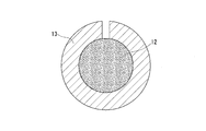
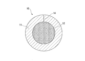
- the manufacturing method of the flux-cored wire 10 according to this embodiment in which the flux 12 is filled in the steel outer shell 11 is a process of filling the flux 12 into the steel plate 13 while forming the steel plate 13 into a cylindrical shape (FIG. 4), joining both ends of the steel plate 13 to form a steel pipe, and rolling and annealing the steel pipe to obtain the flux-cored wire 10. Rolling and annealing are performed to reduce the diameter of the wire 10 to such an extent that it can be used as a welding material and to soften the wire 10.
- the chemical composition of the steel plate 13 is substantially the same as the chemical composition of the steel outer shell 11.
- the joining means is not particularly limited, for example, caulking or welding.
- the wire 10 manufactured by the welding shown in FIG. 6 is a so-called seamless wire having a welded portion 15 but no seam 14. Seamless wire can be used for further heat treatment with the aim of reducing the amount of hydrogen in the wire, and since the amount of moisture absorption after production is small, diffusible hydrogen in the weld metal can be reduced and crack resistance improved. This is preferable.
- the method of manufacturing the flux cored wire 10 includes the step of plating the outer surface of the steel outer shell 11 and / or the steel outer shell 11.
- a step of applying a lubricant to the outer surface may be further included.
- the plating is, for example, copper plating.
- the lubricant is, for example, vegetable oil or PTFE oil.
- the chemical composition of the steel outer skin 11 and the flux 12 is controlled within a predetermined range.
- the component contained in the steel outer shell 11 and the flux 12 melts during welding to form a weld metal, a part of the component is oxidized and discharged as slag to the outside of the weld metal. Therefore, it is considered that the components described below have the same effect regardless of whether they are included in the steel outer shell 11 or the flux 12. For the above reason, in the manufacturing method according to the present embodiment, it is not necessary to distinguish between the chemical composition of the steel outer shell 11 and the chemical composition of the flux 12.
- a chemical composition (component) existing in the form of an oxide or fluoride is defined as a slag component
- a chemical composition (component) existing as a single metal or alloy is defined as an alloy component.
- C, P, and S are not metal elements, but are included in the alloy components in this embodiment for convenience.
- the action of the oxide is considered to be the same as the action of Al and Bi as the alloy components, so that the oxide is substantially handled as the alloy component.
- the content of elements described below is the content of elements present as alloy components.
- the alloy component can be included in both the steel outer shell 11 and the flux 12, the slag component is usually included only in the flux 12.
- the diameter and filling rate of the flux-cored wire 10 to be manufactured refers to the ratio of the mass of the flux 12 to the total mass of the flux-cored wire 10).
- the design value (target value) of the chemical composition of the flux-cored wire 10 is determined in advance.
- the steel plate 13 which is a raw material for the steel outer shell, one having a specific chemical composition is usually used.
- the chemical composition of the steel outer shell 11 can be grasped from a document indicating the chemical composition (for example, the analysis result of the chemical composition of the steel plate 13, the inspection certificate or catalog of the steel manufacturer).
- the design value (target value) of the chemical composition of the flux 12 can be determined from the filling rate, the chemical composition of the steel outer skin 11 and the design value (target value) of the chemical composition of the flux cored wire 10.
- a document for example, a raw material manufacturer showing the chemical composition of the raw material of the flux 12 (which refers to both the raw material of the slag component and the raw material of the metal component) Etc.)
- the raw material of the flux 12 is selected, and the mixing ratio of the raw material is determined. That is, the flux 12 is manufactured by blending the raw materials of the flux 12 selected by the above procedure at the blending ratio determined by the above procedure.
- the flux-cored wire 10 having the chemical composition of the design value can be manufactured using the flux 12 thus manufactured and the steel plate 13 described above.
- the flux-cored wire 10 is plated, it is necessary to control the chemical composition of the steel outer skin 11 and the flux 12 according to the chemical composition of plating and the thickness of plating.
- C is the most basic element necessary for ensuring the strength and hardenability of the weld metal. If the C content is less than 0.03%, the strength required for the weld metal cannot be obtained. Moreover, when C content is less than 0.03%, toughness falls. On the other hand, if the C content exceeds 0.12%, hot cracking is likely to occur, and the strength of the weld metal increases, so that the toughness of the weld metal decreases. Therefore, the C content is 0.03 to 0.12%.
- the lower limit of the C content is 0.04% or 0.05%.
- the upper limit of the C content is 0.07% or 0.06%.
- C may exist as a component of the steel outer shell 11 and as a component of metal powder and alloy powder in the flux 12. That is, by controlling the C content of the steel outer shell 11 and the C content of the flux 12, the flux-cored wire 10 having the C content can be manufactured.
- Si is an element that acts as a deoxidizer during welding. If the Si content is less than 0.20%, the toughness of the weld metal decreases due to insufficient deoxidation. On the other hand, if the Si content exceeds 0.85%, the strength of the weld metal increases and the toughness of the weld metal decreases. Therefore, the Si content is set to 0.20 to 0.85%.
- the lower limit of the Si content is 0.30, 0.40%, or 0.50%.
- the upper limit of Si content is 0.70%, 0.65%, or 0.60%.
- Si can exist as a component of the steel outer shell 11 and a component of alloy powder such as metal Si, Fe—Si, Fe—Si—Mn in the flux 12. That is, by controlling the Si content of the steel outer skin 11 and the Si content of the flux 12, the flux-cored wire 10 having the Si content can be manufactured.
- Mn is an element necessary for ensuring the strength of the weld metal and for assisting deoxidation during welding and ensuring the toughness of the weld metal.
- Mn content is less than 1.50%, the strength and toughness of the weld metal are lowered.
- the Mn content exceeds 3.20%, the strength of the weld metal increases and the toughness decreases. Therefore, the Mn content is 1.50 to 3.20%.
- the lower limit of the Mn content is 1.80, 2.00%, or 2.20%.
- the upper limit of the Mn content is 3.00%, 2.80%, or 2.20%.
- Mn can exist as a component of the steel outer shell 11 and a component of alloy powder such as metal Mn, Fe—Mn, Fe—Si—Mn in the flux 12. That is, by controlling the Mn content of the steel outer shell 11 and the Mn content of the flux 12, the flux-cored wire 10 having the Mn content can be manufactured.
- P and S are most preferably not included in the wire because they are elements that adversely affect the mechanical properties of the weld metal and may impair the corrosion resistance of the weld metal. Therefore, the lower limit of the contents of P and S is 0%. However, since a large amount of cost is required to completely remove P and S from the material of the wire, P and S may be contained within a range that does not impair the properties of the weld metal. In the wire according to the present embodiment, 0.020% or less of P and 0.020% or less of S are allowed. The upper limit value of P or S may be 0.015%, 0.010%, or 0.005%.
- the lower limit value of P or S may be 0.001%, 0.002%, or 0.005%.
- Cu is not an essential component in the method for manufacturing a flux-cored wire according to the present embodiment, but is an element that bears weather resistance and paint peel resistance similarly to Sn, so as to obtain higher weather resistance and paint peel resistance.
- Cu may be contained in the wire in the range of 0 to 0.70%.
- the Cu content is preferably 0.05% or more.
- the Cu content is set to 0.70% or less. More preferably, the lower limit of the Cu content is 0.10%, 0.20%, or 0.30%.
- the upper limit of Cu content is 0.60%, 0.50%, or 0.40%.
- Cu may exist as a component of the steel outer shell 11 itself, a plating component of the steel outer shell 11, or metal Cu in the flux 12. That is, the flux-cored wire 10 having the Cu content can be manufactured by controlling the Cu content of the steel outer shell 11, the Cu content of the plating, and the Cu content of the flux 12.
- Cu improves the weather resistance and paint peel resistance of the weld metal is to reduce the reaction rate of the dissolution reaction (corrosion reaction) of the weld metal itself containing Cu, and in the weld metal containing Cu, Corrosion products (rust) generated on the surface (excess areas, etc.) exhibit a characteristic fine and dense structure, thereby preventing the penetration of water, oxygen, chloride ions, etc. Is to form.
- Sn is an important element for ensuring the weather resistance and paint peel resistance of the weld metal.
- Sn content is less than 0.05%, it is impossible to ensure the weather resistance and paint peel resistance of the weld metal.
- the Sn content is set to 0.05 to 0.40%.
- the lower limit value of the Sn content may be 0.10%, 0.15%, or 0.18%.
- the upper limit value of the Sn content may be 0.30%, 0.25%, or 0.20%.
- Sn may be contained as a component of the steel outer shell 11 or may be contained as a metal Sn or Sn compound in the flux 12.
- Sn may be contained as a component of the steel outer shell 11 or may be contained as a metal Sn or Sn compound in the flux 12.
- the reason why Sn improves the weather resistance and paint peel resistance of the weld metal is that the metal Sn in the weld metal elutes as tin ions (II) (Sn 2+ ) and is exposed to the environment, that is, acid chloride. This is because it exhibits an inhibitory action in a physical solution and suppresses corrosion at the anode whose pH is lowered.
- the metal Sn in the weld metal also has an action (2Fe 3+ + Sn 2+ ⁇ 2Fe 2+ + Sn 4+ ) for reducing iron (III) ions (Fe 3+ ), thereby suppressing the corrosion promoting action of Fe 3+ Improve weatherability in many environments.
- Mg is an element necessary for reducing the amount of oxygen in the weld metal and ensuring the toughness of the weld metal. If the Mg content is less than 0.05%, the toughness of the weld metal decreases. On the other hand, if the Mg content exceeds 0.70%, more spatters are generated during welding, and metal dripping is likely to occur during welding in an upright position and in an upward posture. When the Mg content exceeds 0.70%, the bead appearance and shape are poor in horizontal fillet welding. Therefore, the Mg content is 0.05 to 0.70%. The lower limit of the Mg content may be 0.10%, 0.20%, or 0.25%.
- the upper limit value of the Mg content may be 0.60%, 0.50%, or 0.40%.
- the Mg content of the general steel outer skin 11 is almost 0%.
- Mg is often present in the wire as an alloy powder of metal Mg, Al—Mg, etc. in the flux 12.
- the flux-cored wire 10 having the Mg content can be manufactured by mainly controlling the Mg content of the flux 12.
- TiO 2 converted value of Ti oxides 4.60 to 7.00%
- Ti oxide which is a slag component, becomes the main component of molten slag, imparts appropriate viscosity and melting point to the molten slag, encapsulates the slag throughout the bead, and is particularly resistant to metal in welding, such as standing up and upward. Improves sag. Further, the Ti oxide has an effect of stably maintaining the arc and reducing the amount of spatter generated. When the TiO 2 equivalent value of the Ti oxide is less than 4.60%, the metal tends to sag in welding such as the vertical improvement and upward posture, and a smooth bead cannot be obtained.
- the TiO 2 equivalent value of the Ti oxide exceeds 7.00%, the amount of slag increases, and the lower part of the bead swells in horizontal fillet welding, resulting in a poor bead shape. Further, when the TiO 2 equivalent value of the Ti oxide exceeds 7.00%, slag entrainment is likely to occur. Therefore, the TiO 2 equivalent value of the Ti oxide is 4.60 to 7.00%.
- the lower limit of the TiO 2 converted value of the Ti oxide is 4.80%, 5.00%, or 5.50%.
- the upper limit of the TiO 2 conversion value of the Ti oxide is 6.60%, 6.20%, or 6.00%.
- the Ti oxide may exist mainly as rutile, titanium oxide, titanium slag, illuminite, sodium titanate, potassium titanate, etc. in the flux 12. Therefore, the flux cored wire 10 having the Ti oxide content (4.60 to 7.00% in terms of TiO 2 ) is mainly controlled by controlling the Ti oxide content of the flux 12. Can be manufactured.
- the TiO 2 converted value of the Ti oxide means that all Ti oxides contained in the wire (for example, TiO 2, Ti 2 O 3 , Ti 3 O 5 , sodium titanate, potassium titanate, etc.) are TiO 2. 2 is defined as mass% with respect to the total wire mass of TiO 2 when considered to be 2. Accordingly, the TiO 2 equivalent value is obtained by measuring the total mass of only Ti obtained by excluding O from the mass of the Ti oxide and substituting this total Ti amount into the following formula A.
- TiO 2 conversion value (mass% with respect to the total wire mass of Ti forming the Ti oxide) ⁇ (formula amount of TiO 2 ) / (atomic weight of Ti): formula A
- SiO 2 equivalent value of the Si oxide, the ZrO 2 equivalent value of the Zr oxide, and the FeO equivalent value of the Fe oxide can be obtained by the same calculation.
- SiO 2 converted value of Si oxide 0.20 to 0.90%
- Si oxide which is a slag component, increases the viscosity of the molten slag and adjusts the encapsulation of the slag on the bead.
- SiO 2 equivalent value of the Si oxide is less than 0.20%, the viscosity of the molten slag is insufficient, the slag is not sufficiently encapsulated by horizontal fillet welding, and the bead appearance is poor.
- SiO 2 equivalent value of Si oxide exceeds 0.90%, the melting point of the molten slag is lowered, and metal dripping is likely to occur during welding in an upright position and in an upward posture.
- the SiO 2 equivalent value of the Si oxide is 0.20 to 0.90%.
- the lower limit value of the Si oxide in terms of SiO 2 is 0.30% or 0.40%.
- the upper limit value of the Si oxide in terms of SiO 2 is 0.80%, 0.70%, or 0.60%.
- the Si oxide can exist mainly as silica sand, zircon sand, feldspar, sodium silicate, potassium silicate and the like in the flux 12. Therefore, the flux-cored wire 10 having the Si oxide content (0.20 to 0.90% in terms of SiO 2 ) is mainly controlled by controlling the Si oxide content of the flux 12. Can be manufactured.
- ZrO 2 converted value of Zr oxide 0.10 to 0.70%
- Zr oxide which is a slag component
- Zr oxide has the effect of increasing the melting point of molten slag and improving the metal dripping resistance in welding in a vertical and upward position.
- the slag encapsulation is improved. It has the effect of adjusting and smoothing the bead. If the ZrO 2 conversion value of the Zr oxide is less than 0.10%, those effects cannot be obtained, and metal dripping occurs in welding in the vertical improvement and upward orientation, and in horizontal fillet welding, the slag coverage is not obtained.
- the packaging property is poor and the bead shape is poor.
- the ZrO 2 conversion value of the Zr oxide exceeds 0.70%, the melting point of the molten slag becomes too high, and the metal is likely to sag due to the vertical improvement welding and the upward posture welding. Moreover, if the ZrO 2 conversion value of the Zr oxide exceeds 0.70%, the bead becomes convex in horizontal fillet welding. Furthermore, if the ZrO 2 conversion value of the Zr oxide exceeds 0.70%, the slag becomes dense and hard regardless of the welding position, and the slag peelability becomes poor. Therefore, the ZrO 2 conversion value of the Zr oxide is set to 0.10 to 0.70%.
- the lower limit of the ZrO 2 conversion value of the Zr oxide is 0.20%, 0.30%, or 0.40%.
- the upper limit of the ZrO 2 conversion value of the Zr oxide is 0.60%, 0.50%, or 0.40%.
- the Zr oxide can exist mainly as zircon sand, zirconium oxide or the like in the flux 12 and may be contained in a small amount in the above-described Ti oxide. Therefore, the flux-cored wire 10 having the Zr oxide content (0.10 to 0.70% in terms of ZrO 2 ) is mainly controlled by controlling the Zr oxide content of the flux 12. Can be manufactured.
- Na compound and K compound 0.05 to 0.40% in total of Na 2 O converted value and K 2 O converted value
- the Na compound and the K compound have an effect of stabilizing the arc during welding and an effect of adjusting the bead shape and appearance by adjusting the viscosity of the molten slag during welding.
- the arc becomes unstable during welding, and a lot of spatter is generated.
- the total of Na 2 O converted value and K 2 O converted value of Na compound and K compound is less than 0.05%, the bead shape and the appearance of the bead are deteriorated by horizontal fillet welding.
- the lower limit of the total of Na 2 O converted value and K 2 O converted value of Na compound and K compound is 0.10%, 0.15%, or 0.20%.
- the upper limit of the total of Na 2 O converted value and K 2 O converted value of Na compound and K compound is 0.35%, 0.30%, or 0.25%.
- the Na compound and the K compound may exist as oxides such as feldspar, sodium silicate and potassium silicate in the flux 12, and fluorides such as sodium fluoride, potassium silicate fluoride and cryolite.
- the content of the Na compound and K compound in the normal steel outer shell 11 is approximately 0%. For this reason, the flux-cored wire 10 having the contents of the Na compound and the K compound can be manufactured mainly by controlling the contents of the Na compound and the K compound in the flux 12.
- Na 2 O values of Na compounds when all the Na compound contained in the wire is considered to be Na 2 O, by mass% with respect to Na 2 O of the total wire mass.
- the K 2 O conversion value of K compound when all of the K compound contained in the wire is considered to be K 2 O, by mass% with respect to K 2 O in the total mass of the wire.
- K 2 O conversion value of terms of Na 2 O values and K compounds of Na compound is calculated by the same means as TiO 2 converted value of the above-described Ti oxide.
- the fluorine compound which is a slag component, improves arc concentration and is effective in forming a stable molten pool. Further, the fluorine compound has an action of adjusting the viscosity of the molten slag to smooth the bead shape. If the F-converted value of the fluorine compound is less than 0.02%, the bead shape is not stable in horizontal fillet welding. On the other hand, when the F-converted value of the fluorine compound exceeds 0.25%, the viscosity of the molten slag is excessively lowered, and the metal tends to sag during welding in a standing improvement and upward posture.
- the F-converted value of the fluorine compound is 0.02 to 0.25%.
- the lower limit of the F-converted value of the fluorine compound may be 0.05%, 0.10%, or 0.15%.
- the upper limit value of the F-converted value of the fluorine compound may be 0.22%, 0.20%, or 0.18%.
- the fluoride may exist as sodium fluoride, potassium silicofluoride, magnesium fluoride, cryolite or the like in the flux 12.
- the F-converted value of the fluorine compound is the total amount of the content of F contained in all the fluorine compounds in the wire in mass% with respect to the total mass of the wire.
- the content of the fluorine compound in the normal steel outer skin 11 is almost 0%.
- the flux-cored wire 10 having the above-mentioned fluorine compound content can be manufactured mainly by controlling the fluorine compound content of the flux 12.
- the steel outer shell 11 and the flux 12 have the above elements and compounds as essential requirements (Cu content is not essential), but the elements and compounds described below are further described. Can be contained as needed.
- the manufacturing method of the flux cored wire 10 according to the present embodiment can achieve the problem even when the following optional components are not included, the lower limit value of the content of these optional components is 0. %.
- Ni, Ti, and B have the effect of improving the low temperature toughness of the weld metal, and may be contained in the wire. If the Ni content exceeds 3.00%, hot cracking tends to occur in the weld metal. When the Ti content exceeds 0.50%, the toughness of the weld metal is lowered, the amount of spatter generated is increased, and slag is easily seized on the bead surface. On the other hand, if the B content exceeds 0.010%, hot cracking is likely to occur in the weld metal.
- the Ni content is 3.00% or less
- the Ti content is 0.50% or less
- the B content is 0.010% or less.
- the upper limit with preferable Ni content is 2.60%, 2.20%, or 2.00%.
- the upper limit with preferable Ti content is 0.40%, 0.30%, or 0.20%.
- the upper limit with preferable B content is 0.008%, 0.005%, or 0.003%.
- Ni can exist as a component of the steel outer shell 11 and a component of alloy powder such as metal Ni and Fe—Ni in the flux 12.
- Ti can exist as a component of the steel outer shell 11 and a component of alloy powder such as metal Ti and Fe—Ti in the flux 12.
- B may exist as a component of the steel outer shell 11 and a component of alloy powder such as metal B, Fe—B, Fe—Mn—B in the flux 12. That is, mainly by controlling the Ni content, Ti content and B content of the steel outer shell 11, and the Ni content, Ti content and B content of the flux 12, the Ni content, Ti The flux-cored wire 10 having the B content and the B content can be manufactured.
- the chemical composition (Ni: 0 to 3.00%, Ti: 0 to 0.50%, B : 0 to 0.010%) steel outer shell 11 and the above-mentioned chemical composition (Ni: 0 to 3.00%, Ti: 0 to 0.50%, B: 0 to 0.010%) flux 12 May be used.
- one or more selected from the group consisting of Ni of 0.10% or more, Ti of 0.03% or more, and B of 0.002% or more are used. It is preferable to make it contain in a wire.
- at least one of the following conditions must be satisfied.
- Mo 0 to 0.40% Since Mo has the effect of improving the strength of the weld metal, it may be included in the wire. However, if the Mo content exceeds 0.40%, particularly when the coating film scratches occur in an environment with a large amount of incoming salt, the corrosion depth just below the coating film scratches is suppressed by competing with the ionization of Sn. become unable. Therefore, the Mo content is 0.40% or less. Moreover, in order to acquire the effect of improving the intensity
- Mo can be present in the wire as an alloy powder of a component of the steel outer shell 11, metal Mo, Fe—Mo, or the like. That is, mainly by controlling the Mo content of the steel outer shell 11 and the Mo content of the flux 12, the flux-cored wire 10 having the Mo content can be manufactured. Further, in order to keep the Mo content of the flux-cored wire 10 within the above range, the steel outer skin 11 having the Mo content (that is, 0 to 0.40%) and the Mo content (that is, 0 to 0). .40%) flux 12 may be used.
- W may be included in the wire because it contributes to improving the strength of the weld metal. However, if the W content exceeds 0.200%, particularly when the coating film scratches occur in an environment with a large amount of incoming salt, the corrosion depth just below the coating film scratches is suppressed by competing with the ionization of Sn. become unable. Further, the W content is more preferably 0.010% or less. A preferable upper limit of the W content is 0.150%, 0.100%, or 0.010%. Note that W may be present in the wire as a component of the steel outer shell 11 or as an alloy powder such as metal W.
- the flux-cored wire 10 having the W content can be manufactured. Further, in order to keep the W content of the flux-cored wire 10 within the above range, the steel outer shell 11 having the W content (that is, 0 to 0.200%) and the W content (that is, 0 to 0). .200%) flux 12 may be used.
- Cr 0 to 0.500%
- Cr may be contained in the wire because it contributes to improving the strength of the weld metal.
- the Cr content is 0.500% or less.
- the Cr content is preferably 0.010% or more.
- a preferable upper limit of the Cr content is 0.400% or 0.300%.
- Cr may be present in the wire as a component of the steel outer shell 11 or as an alloy powder of an alloy powder such as metal Cr or Fe—Cr.
- the flux-cored wire 10 having the Cr content can be manufactured mainly by controlling the Cr content of the steel outer skin 11 and the Cr content of the flux 12. Further, in order to keep the Cr content of the flux-cored wire 10 within the above range, the steel outer shell 11 having the Cr content (that is, 0 to 0.500%) and the Cr content (that is, 0 to 0). .500%) flux 12 may be used.
- Nb may be contained in the wire because it contributes to improving the strength of the weld metal by precipitation strengthening. However, if the Nb content exceeds 0.300%, Nb forms coarse precipitates and the toughness of the weld metal decreases. Therefore, the upper limit value of the Nb content is 0.300%. The upper limit value of the Nb content may be 0.250% or 0.200%. In order to acquire the above-mentioned effect, it is good also considering the lower limit of Nb content as 0.050% or 0.100%. Nb may be present in the wire as a component of the steel outer shell 11 or as an alloy powder of an alloy powder such as metal Nb or Fe—Nb.
- the flux-cored wire 10 having the Nb content can be manufactured.
- the steel outer shell 11 having the Nb content (that is, 0 to 0.300%) and the Nb content (that is, 0 to 0) are used. .300%) flux 12 may be used.
- V may be included in the wire because it contributes to improving the strength of the weld metal.
- the V content is 0.300% or less.
- the V content is preferably set to 0.010% or more.
- the upper limit of the preferable V content is 0.200% or 0.100%.
- V may be present in the wire as a component of the steel outer shell 11 or as an alloy powder of an alloy powder such as metal V or Fe—V.
- the flux-cored wire 10 having the V content can be manufactured mainly by controlling the V content of the steel outer skin 11 and the V content of the flux 12. Further, in order to keep the V content of the flux-cored wire 10 within the above range, the steel outer shell 11 having the V content (that is, 0 to 0.300%) and the V content (that is, 0 to 0). .300%) flux 12 may be used.
- N 0 to 0.008% Since N is an element that impairs the toughness and the like of the weld metal, it is most preferable that N is not included in the wire. Therefore, the lower limit of the N content is 0%. However, since a large amount of cost is required to completely remove N from the material of the wire, N may be contained within a range that does not impair various properties of the weld metal. In the wire according to the present embodiment, N of 0.008% or less is allowed. The upper limit of the N content may be 0.007%, 0.006%, or 0.005%.
- the steel outer shell 11 having the N content (that is, 0 to 0.008%) and the N content (that is, 0 to 0.008) are used. %) Flux 12 may be used.
- Ca and REM have a function of improving the ductility and toughness of the weld metal by changing the form of sulfide and oxide.
- the Ca content may be 0.0002% or more, and the REM content may be 0.0002% or more.
- Ca and REM are elements that increase the amount of sputtering and impair the weldability. Therefore, the upper limit of Ca content is 0.0050%, and the upper limit of REM content is 0.0050%.
- the upper limit of the Ca content may be 0.0040% or 0.0030%.
- the upper limit of the REM content may be 0.0040% or 0.0030%.
- Ca and REM may exist in a wire as a component of the steel outer shell 11, or as a Ca compound or a REM compound. That is, mainly by controlling the Ca content and REM content of the steel outer skin 11 and the Ca content and REM content of the flux 12, the flux-cored wire 10 having the above Ca content and REM content is manufactured. can do. Further, since the Ca content and the REM content of the flux-cored wire 10 are within the above ranges, the Ca content (that is, 0 to 0.0050%) and the REM content (that is, 0 to 0.0050%). ) And the flux 12 having the Ca content (that is, 0 to 0.0050%) and the REM content (that is, 0 to 0.0050%) may be used.
- REM refers to a total of 17 elements composed of Sc, Y and lanthanoid, and the “REM content” means the total content of these 17 elements.
- lanthanoid is used as REM
- REM is added industrially in the form of misch metal.
- Sb is an element that imparts weather resistance and paint peel resistance to the weld metal in the same manner as Sn. Therefore, the Sb content may be 0.001% or 0.002%. However, if the Sb content exceeds 0.005%, the toughness of the weld metal decreases due to segregation of Sb to the grain boundaries of the weld metal. Therefore, the Sb content is 0.005% or less. The upper limit value of the Sb content may be 0.004% or 0.003%. Sb may be present in the wire as a component of the steel outer shell 11 or as an alloy powder of an alloy powder such as metal Sb or an Sb compound.
- the flux-cored wire 10 having the Sb content can be manufactured. Further, in order to keep the Sb content of the flux-cored wire 10 within the above range, the steel outer shell 11 having the Sb content (that is, 0 to 0.005%) and the Sb content (that is, 0 to 0). 0.005%) flux 12 may be used.
- Fe oxide 0 to 2.50% in terms of FeO
- the lower limit of the FeO equivalent value of Fe oxide is 0%.
- Fe oxide impairs welding workability and hinders all-position welding. Accordingly, the upper limit of the FeO equivalent value of the Fe oxide is set to 2.50%. It is good also considering the lower limit of the FeO conversion value of Fe oxide as 0.10% or 0.50%. It is good also considering the upper limit of the FeO conversion value of Fe oxide as 2.00% or 1.50%.
- the Fe oxide is mainly present in the flux 12, and mainly by controlling the content of the Fe oxide in the flux 12, the content of the Fe oxide (from 0 to 2 in terms of FeO). 50%) flux-cored wire 10 can be manufactured.
- Al and Al oxide increase the melting point of the molten slag and have the effect of making it difficult to cause metal sag in welding in an upright position and in an upward posture, and thus may be contained in the wire.
- the total of Al and Al converted values of Al and Al oxides exceeds 0.60%, the lower part of the bead swells in horizontal fillet welding, resulting in poor appearance.
- the sum of Al and Al converted values of Al oxide exceeds 0.60%, slag entrainment is likely to occur. Therefore, the sum of Al and Al oxide in terms of Al is 0.60% or less.
- the total of Al and Al oxide converted values may be 0.50% or 0.40%.
- the total Al conversion value of the Al oxide is set to 0.01% or more, 0.05%, or 0.10%. It is preferable.
- the Al oxide may exist as alumina or feldspar in the flux 12.
- Metal Al or alloy Al may exist as a component of the steel outer shell 11, or as metal Al powder, Fe—Al alloy powder, Al—Mg alloy powder, etc. in the flux 12. That is, mainly by controlling the Al content of the steel outer shell 11 and the Al content and Al oxide content of the flux 12, the flux-cored wire having the Al content and Al oxide content described above is used. 10 can be manufactured.
- the chemical composition (Al and Al oxide: 0 to 0.60% in total of Al conversion values)
- a steel outer shell 11 and a flux 12 having the above chemical composition (Al and Al oxide: 0 to 0.60% in total in terms of Al) may be used.
- the Al converted value is a total value of mass% with respect to the total mass of Al wire present as a metal or alloy and mass% with respect to the total mass of Al wire in the Al oxide.
- the Al conversion value of the Al oxide (AlO X ) is obtained by the following formula B.
- (Al converted value of Al oxide (AlO X )) (content in mass% of Al oxide (AlO X ) with respect to the total mass of the flux-cored wire) ⁇ (Atom weight of Al) / (Al oxide (AlO X ) Formula weight):
- the Al converted value of the flux-cored wire 10 is the sum of the Al converted values of the respective Al oxides (AlO x , AlO y ,).
- the content of Al present as a metal or an alloy and the Al oxide in the method for manufacturing the flux-cored wire 10 according to the present embodiment It was decided to manage both of the content of Al as an Al conversion value.
- Bi and Bi oxide may be included in the wire because they have an effect of improving the slag peelability from the weld bead.
- the total Bi converted value of Bi and Bi oxide is set to 0.035% or less.
- the upper limit with the preferable Bi conversion value of Bi and Bi oxide is 0.030% or 0.025%.
- Bi and Bi oxide may exist as powders, such as metal Bi and Bi oxide.
- the steel plate 13 containing Bi is very expensive. Therefore, the flux-cored wire 10 having the Bi content and the Bi oxide content can be manufactured mainly by controlling the Bi content and the Bi oxide content of the flux 12. Further, in order to keep the Bi content and the Bi oxide content of the flux-cored wire 10 within the above ranges, the chemical composition (Bi and Bi oxide: 0 to 0.035% in total of Bi conversion values) A steel outer shell 11 and a flux 12 having the above-described chemical composition (Bi and Bi oxide: 0 to 0.035% in total of Bi conversion values) may be used.
- the Bi-converted value is a total value of mass% with respect to the total mass of Bi wire existing as a metal or alloy and mass% with respect to the total mass of Bi wire in Bi oxide (for example, Bi 2 O 3 ). Since Bi present as a metal or an alloy and Bi oxide have the same effect, in the method for manufacturing the flux cored wire 10 according to the present embodiment, the content of Bi present as a metal or an alloy, and Bi oxide It was decided to manage both of the contents as Bi converted values.
- the total content of Sn and Sb needs to exceed the total content of Mo and W. This is because, especially in an environment where the amount of incoming salt is large, if the coating film is damaged due to deterioration of the coating film, it is difficult to suppress the corrosion depth just below the coating film scratched part, and the paint peel resistance is reduced. is there.
- the above-mentioned requirement can be paraphrased that the index X obtained by substituting the contents of Sn, Sb, Mo, and W into the following formula C is greater than zero.
- the wire component is preferably controlled so that the index X is 0.05 or more, 0.08 or more, or 0.10 or more.
- Index X (Sn + Sb) ⁇ (Mo + W): Formula C
- the element symbol in Formula C indicates the content of the element related to each element symbol in mass% with respect to the total mass of the flux-cored wire.
- the balance of the wire components is Fe and impurities.
- Fe exists as a component of the steel outer shell 11 and a component in the flux 12 (Fe powder, Fe alloy powder (eg, Fe—Mn alloy powder, Fe—Si alloy powder, etc.).
- Fe powder is a component other than Fe. If it is not necessary, the content may be 0% with respect to the total mass of the wire. If the Fe powder content is excessive, welding is performed with iron oxide on the surface of the Fe powder. Therefore, the upper limit of the Fe powder content may be set to 10.0% or less with respect to the total mass of the wire.
- the wire according to the embodiment may contain O as an impurity in addition to O constituting the oxide, but such O is allowed if the content is 0 to 0.080%.
- the content of all O, including O constituting Ti oxide, Si oxide, Zr oxide, Fe oxide, Al oxide, Na compound, K compound, fluorine compound, and Bi oxide is 0 It is usually from 5 to 6.0%.
- the filling rate (the ratio of the total mass of the flux 12 to the total mass of the wire) is not particularly limited, but is 8 to 20% with respect to the total mass of the wire from the viewpoint of productivity. Is preferred.
- the diameter of the wire is not particularly limited, but is preferably 1.0 to 2.0 mm in consideration of convenience during welding.
- the flux cored wire 10 according to another aspect of the present invention is the flux cored wire 10 obtained by the above-described method for manufacturing the flux cored wire 10 according to the present embodiment.
- the method for manufacturing a welded joint according to another aspect of the present invention includes the step of welding using the flux-cored wire 10 manufactured by the method for manufacturing the flux-cored wire 10 according to this embodiment described above. Is the method.
- the flux cored wire 10 according to the present embodiment has an Sn content of 0.05 to 0.40%, and the Sn content, the Sb content, the W content, and the Mo content satisfy the above formula C.
- the method for manufacturing the flux-cored wire 10 and the welded joint according to the present embodiment can provide a weld metal that is excellent in weather resistance and paint peel resistance in an environment where a corrosive substance is present, such as a large amount of incoming salt. Further, since the flux-cored wire 10 according to the present embodiment has an alloy component within the above-mentioned predetermined range, the flux-cored wire 10 and the method for manufacturing a welded joint according to the present embodiment are weld metals having excellent mechanical properties. A welded joint is obtained.
- the flux-cored wire 10 according to the present embodiment is manufactured from a material having a slag component within the above-described range, the flux-cored wire 10 and the method for manufacturing a welded joint according to the present embodiment are all Good welding workability can be ensured in posture welding.
- the use of the flux-cored wire 10 and the welded joint manufacturing method according to the present embodiment is not particularly limited, but structural steel materials that require corrosion resistance of the weld metal, in particular, harbor facilities, bridges, building / civil engineering structures and tanks, It is particularly suitable to be applied to the manufacture of steel structures such as ships / marine structures, railways and containers.
- the material of the steel material to which the manufacturing method of the flux cored wire 10 and the welded joint according to the present embodiment is not particularly limited, and may be a normal steel material such as carbon steel or low alloy steel. Weather resistant steel or low alloy steel containing Ni, Sn and the like is more advantageous from the viewpoint of weather resistance and paint corrosion resistance.
- the form of welding in which the flux cored wire 10 according to the present embodiment is provided and the form of welding included in the method for manufacturing the welded joint according to the present embodiment are not particularly limited, but are preferably gas shielded arc welding. .
- analysis of the component of the flux cored wire 10 obtained by the manufacturing method of the flux cored wire 10 according to the present embodiment is difficult. This is because it is difficult to specify the components of the non-metallic substance of the flux 12 by analysis. It is not easy to determine whether an element such as Si contained as a non-metallic substance exists in the coating material in the form of a metal or an alloy, an oxide, a fluoride, or a carbonate. Absent. For example, it is difficult to separate Si (metal Si) existing as a metal or an alloy and Si existing as an oxide (SiO 2 ). This is because a method for performing wet analysis by selectively dissolving only metal Si has not been established.
- the manufacturing method of the flux cored wire 10 includes a step of annealing the steel wire in which the flux 12 is encapsulated, and this annealing may change the composition of the non-metallic substance of the flux 12 to an unexpected one.
- SPCC specified in JIS G 3141: 2011 “Cold Rolled Steel Sheet and Steel Strip” is used as a steel outer shell, and after filling with flux, the diameter is reduced (intermediate annealing once for softening and dehydrogenation of outer shell).
- a seamless type having the components shown in Table 1-1 to Table 1-3, having a filling rate of 13.5%, a wire diameter of 1.2 mm, and having no gaps penetrating the steel outer skin.
- Various types of flux-cored wires were manufactured. However, A23 was manufactured by caulking.
- the numerical values in Table 1-1 to Table 1-3 represent mass% with respect to the total mass of the flux-cored wire (the total mass of the steel outer sheath and the flux).
- the values listed in Table 1-1 to Table 1-3 are design values.
- the content of each compound was controlled based on an analysis report, certificate or catalog of the chemical composition of the raw material of the flux.
- the case where the molten metal dripped during the welding and the bead was not formed was also determined as “bad”.
- the amount of spatter generated was “large” when the sputter mass per minute per minute was 1.5 g or more, and “small” when it was less than 1.5 g.
- the slag peelability is defined as “very good” when the slag is peeled off regardless of the hit by the chisel, and the slag is peeled off by hitting with the chisel (the slag does not peel off without hitting by the chisel).
- the case was determined as “good”, and the case where slag remained on the bead after hitting with a chisel was determined as “bad”.
- the mechanical properties and corrosion resistance of the weld metal were evaluated in accordance with JIS Z 3111: 2005 “Method of tensile and impact test of weld metal”.
- the impact test and the corrosion resistance evaluation test were carried out.
- the base material used contained C: 0.11%, Si: 0.18%, Mn: 1.44%, P: 0.011%, S: 0.002%, Sn: 0.12%. It is a corrosion-resistant steel plate.
- the welding conditions in the weld metal test were the conditions shown in Table 2.
- the welding conditions in the corrosion resistance evaluation test were the same as the welding conditions in the weld metal test.
- the acceptance criteria for the mechanical properties of the weld metal were that the tensile strength in the tensile test was 510 to 660 MPa and the absorbed energy in the impact test at 0 ° C. was 60 J or more. Passing the mechanical properties of the weld metal obtained from wires (A9, A11, A12, B1, B2, B10, B13, and B14) added with one or more of Ni, Ti, and B to ensure low temperature toughness With respect to the judgment criteria, those having a tensile strength of the weld metal of 510 to 660 MPa and an absorption energy of ⁇ 40 ° C. of the weld metal of 60 J or more were determined to be acceptable.
- the tensile strength is 590 to 720 MPa
- the absorbed energy at 0 ° C is 60 J or more. It was.
- a sample for preparing a test piece (thickness 3 mm ⁇ width 60 mm ⁇ length 150 mm) is 1 mm deep from the surface of the base material 1 so that the weld metal 2 is at the center. After the sample was collected from the sampling position 3 and the surface thereof was shot blasted, it was dried by heating at a furnace temperature of 80 ° C. to obtain a corrosion test piece material. Next, on either surface of the corrosion test piece material, either paint A (Chinese Paint Co., Ltd. Van No. # 200) or Paint B (Shinto Paint Co., Ltd. Neo Gosei Primer HB) is applied to the steel surface.
- paint A Choinese Paint Co., Ltd. Van No. # 200
- Paint B Shinto Paint Co., Ltd. Neo Gosei Primer HB
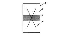
- a corrosion test piece was prepared by coating with a thickness of 200 to 350 ⁇ m. As shown in FIG. 2, a cross-cut 4 was applied to the test piece so as to straddle the weld metal 2 to produce a corrosion test piece 5 simulating a coating film scratch. The crosscut 4 was formed by applying a scratch wrinkle reaching from the top of the coating film to the underlying steel surface with a cutter knife so that the rectangular dimension with the crosscut as a diagonal line is 100 mm long side ⁇ 40 mm short side. Thereafter, the corrosion resistance of the obtained corrosion test piece 5 was evaluated according to SAE (Society of Automotive Engineers) J2334 test.
- SAE Society of Automotive Engineers
- the SAE J2334 test will be described.
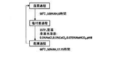
- the SAE J2334 test is wet (50 ° C., 100% RH, 6 hours), salt adhesion (0.5 wt% NaCl, 0.1 wt% CaCl 2 , 0.075 wt% NaHCO 3 aqueous solution immersion, 0.25 Time) and drying (60 ° C., 50% RH, 17.75 hours) are accelerated tests conducted under dry and wet conditions with one cycle (24 hours in total). An outline of one cycle is shown in FIG.
- This corrosion test is a test that simulates a severe corrosive environment in which the amount of incoming salt exceeds 1 mdd. After 80 cycles of the SAE J2334 test, the coating film peeling / swelling area ratio of each test piece was measured. In addition, coating adhesion was evaluated as a test reflecting the long-term paint corrosion resistance of actual structures. Paste two rows of transparent adhesive tapes with a width of 20 mm, cut to a long side length of 100 mm, over the entire area corresponding to the rectangle with the cross cut as a diagonal, and within 5 minutes after attaching the tape. It was separated at 4.0 to 8.0 seconds at an angle close to 60 °.
- the tape peeling rate was determined by dividing the area of the coating film peeled off by the tape peeling operation with the area of the coating film remaining immediately after 80 cycles of the SAE J2334 test. Thereafter, the remaining coating film on the surface and the generated rust layer were removed, and after measuring the corrosion depth of the paint film ridge, the average corrosion depth was calculated.
- the acceptance criteria for weather resistance and paint peel resistance were determined to be acceptable when the coating film peeling / bulging area ratio was less than 50% and the coating film scratch average corrosion depth was less than 0.50 mm. Furthermore, for the wires added with Cu (A6 to A9, A17, A18, B7 to B11), the coating film peeling / bulging area ratio is less than 20%, and the coating film scratched portion average corrosion depth is less than 0.25 mm. The case was passed. In the evaluation of coating film adhesion, a tape peeling rate of 0 to less than 20% was judged as “very good”, 20% or more and less than 40% was judged as “good”, and 50% or more was judged as “bad”. These results are summarized in Table 3-1 and Table 3-2.
- wire symbols A1 to A25 are examples of the present invention
- wire symbols B1 to B15 are comparative examples. Since the wire symbols A1 to A25, which are examples of the present invention, are within the respective component ranges defined in the examples of the present invention, the bead shape is good and the slag is peeled off in fillet welding in each of the horizontal, vertical and upward postures. The amount of spatter and the amount of spatter is small, there is no defect in the X-ray transmission test, the tensile strength and absorbed energy of the weld metal are good, the paint peeling and swelling area ratios are all less than 50%, and the corrosion depth of the paint scratches is All were less than 0.5 mm, which was a very satisfactory result.
- the wire symbols A9, A11, and A12 containing one or more of Ni, Ti, and B had an absorption energy of ⁇ 40 ° C. of the weld metal of 60 J or more.
- the wire symbols A6, A7, A8, A9, A17, and A18 containing Cu are less than 20% of the coating film peeling / swelling area ratio and the average corrosion depth of the coating film scratched part in the corrosion resistance evaluation test of the welded part. Was less than 0.25 mm. Since the wire symbols A8, A10, and A11 contain appropriate amounts of Al and Al oxide in terms of Al, the rise and upward bead shapes were particularly good. Since the wire symbols A8 and A13 contained an appropriate amount of Bi, they exhibited excellent slag peelability.
- the wire symbol B1 since the wire symbol B1 has a small TiO 2 conversion value, metal sagging occurred due to vertical improvement and upward fillet welding, and a smooth bead could not be obtained. Further, since the wire symbol B1 has a small amount of Mn, the tensile strength of the deposited metal was low and the absorbed energy was low. Furthermore, since the wire symbol B1 has a large amount of B, crater cracking occurred. Since the wire symbol B2 has a large TiO 2 converted value, the bead shape was poor in horizontal fillet welding, and slag was caught in the X-ray transmission test. Moreover, since the wire symbol B2 has a small amount of C, the tensile strength and absorbed energy of the weld metal were low.
- the wire symbol B3 had a small SiO 2 equivalent value, the bead shape was poor in horizontal fillet welding. Moreover, since the wire symbol B3 has a large amount of Mn, the tensile strength of the deposited metal was high and the absorbed energy was low. Since the wire symbol B4 has a large SiO 2 conversion value, a metal bead was caused by vertical rise and upward fillet welding, and a smooth bead could not be obtained. Moreover, as for wire symbol B4, the absorbed energy of the weld metal was low. Furthermore, since the wire symbol B4 has a small amount of Sn, the coating metal peeling and swelling area ratio of the weld metal was large, and the average corrosion depth of the coating film scratched part was also deep.
- the wire symbol B5 Since the wire symbol B5 has a small ZrO 2 converted value, the bead shape was poor in fillet welding in all the evaluated postures. Moreover, since the wire symbol B5 has a small amount of Si, the absorbed energy of the deposited metal was low. Since the wire symbol B6 has a large ZrO 2 converted value, the bead shape was poor in fillet welding in all the evaluated postures. Moreover, since the wire symbol B6 has a small amount of Mg, the absorbed energy of the deposited metal was low.
- the wire symbol B7 Since the wire symbol B7 has a large amount of Si, the tensile strength of the deposited metal was high and the absorbed energy was low. Moreover, since the wire symbol B7 had a small total of Na 2 O converted value and K 2 O converted value, the bead shape was poor in horizontal fillet welding, and the amount of spatter was large. Since the wire symbol B8 had a large amount of Mg, the bead shape was poor and the amount of spatter was large in fillet welding in all the evaluated postures. Moreover, since the wire symbol B8 has a large amount of Sn, the absorbed energy of the deposited metal was low.
- the wire symbol B9 had a large bead shape in the fillet welding of all the evaluated postures because the sum of the Na 2 O converted value and the K 2 O converted value was large. Moreover, since the wire symbol B9 had a large sum of Bi and Bi converted values of Bi oxide, crater cracking occurred.
- the wire symbol B10 Since the wire symbol B10 has a large F-converted value, the bead shape was poor in fillet welding in all the evaluated postures. Moreover, since the wire symbol B10 has a large amount of Cu, the absorbed energy of the weld metal was low. Since the wire symbol B11 has a small F-converted value, the bead shape was poor in horizontal fillet welding. Moreover, since the wire symbol B11 had a large amount of Mo, the tensile strength of the weld metal was high and the absorbed energy was low. Furthermore, the wire number B11 had an insufficient index X (ie, Sn + Sb> Mo + W was not satisfied), and thus the coating film adhesion was poor.
- X ie, Sn + Sb> Mo + W was not satisfied
- the wire symbol B12 Since the wire symbol B12 has a small amount of C, the tensile strength and absorbed energy of the weld metal were low. In addition, since the wire symbol B12 has a large sum of Al and Al 2 O 3 in terms of Al, the bead shape was poor in horizontal fillet welding, and slag was caught in the X-ray transmission test.
- the wire symbol B13 Since the wire symbol B13 has a small SiO 2 conversion value, the bead shape was poor in horizontal fillet welding. Moreover, since the wire symbol B13 has a large amount of Ni, crater cracking occurred. Since the wire symbol B14 had a small amount of Sn, the coating film peeling / swelling area ratio of the deposited metal was large, and the average corrosion depth of the coating film scratched part was also deep. Further, since the wire symbol B14 has a large amount of Ti, it has a large amount of spatter and a poor slag peelability. Further, in the wire symbol B14, the absorbed energy of the weld metal was low. Since the wire symbol B15 has a large amount of C, the tensile strength of the deposited metal was high and the absorbed energy was low. Further, crater cracking occurred in the wire symbol B15.
Abstract
Description
(1)本発明の一態様に係る鋼製外皮の内部にフラックスが充填されたフラックス入りワイヤの製造方法は、鋼板を円筒形に成形しながら、前記鋼板の内部にフラックスを充填する工程と、前記鋼板の両端を接合して鋼管とする工程と、前記鋼管に圧延及び焼鈍を施して、前記フラックス入りワイヤを得る工程と、を備え、前記フラックス入りワイヤの化学組成が、前記フラックス入りワイヤの全質量に対する質量%で、C:0.03~0.12%、Si:0.20~0.85%、Mn:1.50~3.20%、P:0.020%以下、S:0.020%以下、Mg:0.05~0.70%、Sn:0.05~0.40%、Ti酸化物:TiO2換算値で4.60~7.00%、Si酸化物:SiO2換算値で0.20~0.90%、Zr酸化物:ZrO2換算値で0.10~0.70%、Cu:0~0.70%、Ni:0~3.00%、Ti:0~0.50%、B:0~0.010%、Mo:0~0.40%、W:0~0.200%、Cr:0~0.500%、Nb:0~0.300%、V:0~0.300%、N:0~0.008%、Ca:0~0.0050%、REM:0~0.0050%、Sb:0~0.005%、Fe酸化物:FeO換算値で0~2.50%、Al及びAl酸化物の合計:Al換算値で合計0~0.60%、Bi及びBi酸化物の合計:Bi換算値で合計0~0.035%、Na化合物及びK化合物:Na2O換算値及びK2O換算値の合計で0.05~0.40%、弗素化合物:F換算値で0.02~0.25%、残部:Fe及び不純物であり、Sn含有量、Sb含有量、W含有量、及びMo含有量が以下の式1を満たす。
Sn+Sb>Mo+W:式1
ただし、前記式1における元素記号は、各元素記号に係る元素の含有量を、前記フラックス入りワイヤの前記全質量に対する質量%で示すものである。
(2)ある上記(1)に記載のフラックス入りワイヤの製造方法では、前記フラックス入りワイヤの化学組成が、前記フラックス入りワイヤの前記全質量に対する質量%で、W:0~0.010%、Mo:0~0.04%であってもよい。
(3)上記(1)又は(2)に記載のフラックス入りワイヤの製造方法では、前記フラックス入りワイヤの化学組成が、前記フラックス入りワイヤの前記全質量に対する質量%で、Cu:0.05~0.70%、であってもよい。
(4)上記(1)~(3)のいずれか一項に記載のフラックス入りワイヤの製造方法では、前記フラックス入りワイヤの化学組成が、前記フラックス入りワイヤの前記全質量に対する質量%で、少なくとも下記のいずれかひとつを満たしてもよい。
Ni:0.10~3.00%
Ti:0.03~0.50%
B:0.002~0.010%
(5)上記(1)~(4)のいずれか一項に記載のフラックス入りワイヤの製造方法では、前記接合がかしめであってもよい。
(6)上記(1)~(4)のいずれか一項に記載のフラックス入りワイヤの製造方法では、前記接合が溶接であってもよい。
(7)本発明の別の態様に係るフラックス入りワイヤは、上記(1)~(6)のいずれか一項に記載のフラックス入りワイヤの製造方法によって製造される。
(8)本発明の別の態様に係る溶接継手の製造方法は、上記(1)~(6)のいずれか一項に記載のフラックス入りワイヤの製造方法によって製造されるフラックス入りワイヤを用いて溶接する工程を備える。
本実施形態に係るフラックス入りワイヤ10を製造しようとする際には、製造しようとするフラックス入りワイヤ10の径、充填率(フラックス入りワイヤ10の全質量に対するフラックス12の質量の割合のことをいう。)およびフラックス入りワイヤ10の化学組成の設計値(目標値)が予め決定される。鋼製外皮の原材料となる鋼板13には、通常、特定の化学組成のものが使用される。その化学組成を示した書類(例えば、鋼板13の化学組成の分析結果、鉄鋼メーカの検査証明書またはカタログなど)から鋼製外皮11の化学組成を把握できる。このため、充填率、鋼製外皮11の化学組成およびフラックス入りワイヤ10の化学組成の設計値(目標値)から、フラックス12の化学組成の設計値(目標値)を決定することができる。決定されたフラックス12の化学組成の設計値(目標値)に加え、フラックス12の原料(スラグ成分の原料および金属成分の原料の双方をいう。)の化学組成を示した書類(例えば、原料メーカなどの報告書、証明書またはカタログなど)から、フラックス12の原料が選定され、その原料の配合比率が決定される。
つまり、上記の手順で選定されたフラックス12の原料を、上記の手順で決定された配合比率で配合して、フラックス12を製造する。このようにして製造されたフラックス12および前記の鋼板13を用いて、設計値の化学組成のフラックス入りワイヤ10を製造することができる。なお、フラックス入りワイヤ10にめっきが施される場合、めっきの化学組成とめっきの厚さに応じて、鋼製外皮11およびフラックス12の化学組成を制御する必要がある。
Cは、溶接金属の強度及び焼入れ性を確保するために必要な、最も基本的な元素である。C含有量が0.03%未満では、溶接金属に必要な強度が得られない。また、C含有量が0.03%未満である場合、靭性が低下する。一方、C含有量が0.12%を超えると、高温割れが生じやすくなり、また溶接金属の強度が高くなることにより溶接金属の靭性が低下する。したがって、C含有量は、0.03~0.12%とする。好ましくは、C含有量の下限値は0.04%、又は0.05%である。好ましくは、C含有量の上限値は0.07%、又は0.06%である。なお、Cは、鋼製外皮11の成分、及びフラックス12中の金属粉及び合金粉の成分として存在し得る。つまり、鋼製外皮11のC含有量およびフラックス12のC含有量を制御することにより、前記のC含有量のフラックス入りワイヤ10を製造することができる。
Siは、溶接時の脱酸剤として働く元素である。Si含有量が0.20%未満であると、脱酸不足により溶接金属の靭性が低下する。一方、Si含有量が0.85%を超えると、溶接金属の強度が高くなり、溶接金属の靭性が低下する。したがって、Si含有量は、0.20~0.85%とする。好ましくは、Si含有量の下限値は0.30、0.40%又は0.50%である。好ましくは、Si含有量の上限値は0.70%、0.65%、又は0.60%である。なお、Siは、鋼製外皮11の成分、及びフラックス12中の金属Si、Fe-Si、Fe-Si-Mn等の合金粉の成分として存在し得る。つまり、鋼製外皮11のSi含有量およびフラックス12のSi含有量を制御することにより、前記のSi含有量のフラックス入りワイヤ10を製造することができる。
Mnは、溶接金属の強度を確保するために、また、溶接時の脱酸を補助し溶接金属の靱性を確保するために必要とされる元素である。Mn含有量が1.50%未満であると、溶接金属の強度及び靱性が低下する。一方、Mn含有量が3.20%を超えると、溶接金属の強度が高くなり靱性が低下する。したがって、Mn含有量は、1.50~3.20%とする。好ましくは、Mn含有量の下限値は1.80、2.00%、又は2.20%である。好ましくは、Mn含有量の上限値は3.00%、2.80%、又は2.20%である。なお、Mnは、鋼製外皮11の成分、及びフラックス12中の金属Mn、Fe-Mn、Fe-Si-Mn等の合金粉の成分として存在し得る。つまり、鋼製外皮11のMn含有量およびフラックス12のMn含有量を制御することにより、前記のMn含有量のフラックス入りワイヤ10を製造することができる。
[S:0.020%以下]
P及びSは、溶接金属の機械特性に悪影響を与え、また、溶接金属の耐食性を損なう場合がある元素であるので、ワイヤに含まれないことが最も好ましい。従って、P及びSの含有量の下限値は0%である。しかしながら、P及びSをワイヤの材料から完全に除去するためには多くの費用が必要とされるので、溶接金属の諸特性を損なわない範囲内でP及びSが含有されてもよい。本実施形態に係るワイヤでは、0.020%以下のP、及び0.020%以下のSが許容される。P又はSの上限値を0.015%、0.010%、又は0.005%としてもよい。P又はSの下限値を0.001%、0.002%、又は0.005%としてもよい。前記のCおよびSiと同様に、鋼製外皮11のP含有量およびS含有量並びにフラックス12のP含有量およびS含有量を制御することにより、前記のP含有量およびS含有量のフラックス入りワイヤ10を製造することができる。
Cuは、本実施形態に係るフラックス入りワイヤの製造方法において必須成分ではないが、Snと同様に耐候性及び耐塗装剥離性を担う元素であり、より高い耐候性及び耐塗装剥離性を得るために、Snに加えてCuを0~0.70%の範囲でワイヤに含有させてもよい。より高い耐候性及び耐塗装剥離性を発揮させるためには、Cu含有量を0.05%以上とすることが好ましい。しかし、Cu含有量が0.70%を超えると、溶接金属の靭性が低下する。したがって、Cu含有量は、0.70%以下とする。さらに好ましくは、Cu含有量の下限値は0.10%、0.20%、又は0.30%である。さらに好ましくは、Cu含有量の上限値は0.60%、0.50%、又は0.40%である。なお、Cuは、鋼製外皮11自体の成分、鋼製外皮11のめっき成分、又はフラックス12中の金属Cu等として存在し得る。つまり、鋼製外皮11のCu含有量、めっきのCu含有量およびフラックス12のCu含有量を制御することにより、前記のCu含有量のフラックス入りワイヤ10を製造することができる。
Snは、溶接金属の耐候性及び耐塗装剥離性を確保するために重要な元素である。Sn含有量が0.05%未満であると、溶接金属の耐候性及び耐塗装剥離性の確保ができない。一方、Sn含有量が0.40%を超えると、溶接金属の粒界へのSnの偏析により、溶接金属の靭性が低下する。したがって、Sn含有量は、0.05~0.40%とする。好ましくは、Sn含有量の下限値を0.10%、0.15%、又は0.18%としてもよい。好ましくは、Sn含有量の上限値を0.30%、0.25%、または0.20%としてもよい。なお、Snは、鋼製外皮11の成分として含有されてもよいし、フラックス12中の金属Sn又はSn化合物として含有されてもよい。主に、鋼製外皮11のSn含有量およびフラックス12のSn含有量を制御することにより、前記のSn含有量のフラックス入りワイヤ10を製造することができる。
Mgは、溶接金属中の酸素量を低減し、溶接金属の靭性を確保するために必要な元素である。Mg含有量が0.05%未満であると、溶接金属の靭性が低下する。一方、Mg含有量が0.70%を超えると、溶接中に発生するスパッタが多くなり、また、立向上進及び上向姿勢の溶接でメタル垂れが生じやすくなる。Mg含有量が0.70%を超えると、水平すみ肉溶接では、ビード外観及び形状が不良となる。したがって、Mg含有量は、0.05~0.70%とする。Mg含有量の下限値を0.10%、0.20%、又は0.25%としてもよい。Mg含有量の上限値を0.60%、0.50%、又は0.40%としてもよい。一般的な鋼製外皮11のMg含有量は殆ど0%である。このため、Mgは、フラックス12中の金属Mg、Al-Mg等の合金粉末としてワイヤに存在することが多い。つまり、主にフラックス12のMg含有量を制御することにより、前記のMg含有量のフラックス入りワイヤ10を製造することができる。
スラグ成分であるTi酸化物は、溶融スラグの主成分となり、溶融スラグに適度な粘性と融点を与え、ビード全体にスラグを被包させ、特に立向上進及び上向姿勢等の溶接における耐メタル垂れ性を向上させる。また、Ti酸化物には、アークを安定に持続させ、スパッタ発生量を低減させる効果がある。Ti酸化物のTiO2換算値が4.60%未満では、立向上進及び上向姿勢等の溶接においてメタルが垂れやすくなり、平滑なビードが得られない。一方、Ti酸化物のTiO2換算値が7.00%を超えると、スラグ量が多くなり、水平すみ肉溶接においてビード下部が膨らみ、ビード形状が不良になる。また、Ti酸化物のTiO2換算値が7.00%を超えると、スラグ巻き込みが発生しやすい。したがって、Ti酸化物のTiO2換算値は、4.60~7.00%とする。好ましくは、Ti酸化物のTiO2換算値の下限値は4.80%、5.00%、又は5.50%である。好ましくは、Ti酸化物のTiO2換算値の上限値は6.60%、6.20%、又は6.00%である。なお、Ti酸化物は、主に、フラックス12中のルチル、酸化チタン、チタンスラグ、イルミナイト、チタン酸ソーダ、チタン酸カリ等として存在し得る。このため、主に、フラックス12のTi酸化物の含有量を制御することにより、前記のTi酸化物の含有量(TiO2換算値で4.60~7.00%)のフラックス入りワイヤ10を製造することができる。
(TiO2換算値)=(Ti酸化物を形成するTiのワイヤ全質量に対する質量%)×(TiO2の式量)/(Tiの原子量):式A
Si酸化物のSiO2換算値、Zr酸化物のZrO2換算値、Fe酸化物のFeO換算値も、同様の計算により得られる。
スラグ成分であるSi酸化物は、溶融スラグの粘性を高め、ビード上のスラグの被包性を調整する。Si酸化物のSiO2換算値が0.20%未満では、溶融スラグの粘性が不足し、水平すみ肉溶接でスラグの被包が不十分となり、ビード外観が不良になる。一方、Si酸化物のSiO2換算値が0.90%を超えると、溶融スラグの融点が低下し、立向上進及び上向姿勢の溶接でメタル垂れが発生しやすくなる。また、Si酸化物のSiO2換算値が0.90%を超えると、溶接金属の酸素量が増えて靭性が低下する。したがって、Si酸化物のSiO2換算値は、0.20~0.90%とする。好ましくは、Si酸化物のSiO2換算値の下限値は0.30%、又は0.40%である。好ましくは、Si酸化物のSiO2換算値の上限値は、0.80%、0.70%、又は0.60%である。なお、Si酸化物は、主に、フラックス12中の珪砂、ジルコンサンド、長石、珪酸ソーダ、珪酸カリ等として存在し得る。このため、主に、フラックス12のSi酸化物の含有量を制御することにより、前記のSi酸化物の含有量(SiO2換算値で0.20~0.90%)のフラックス入りワイヤ10を製造することができる。
スラグ成分であるZr酸化物は、溶融スラグの融点を高め、立向上進及び上向姿勢の溶接において耐メタル垂れ性を向上させる効果があり、水平すみ肉溶接においては、スラグの被包性を調整し、ビードを平滑にする効果がある。Zr酸化物のZrO2換算値が0.10%未満では、それらの効果が得られず、立向上進及び上向姿勢の溶接において、メタル垂れが生じ、水平すみ肉溶接においては、スラグの被包性が悪く、ビード形状が不良となる。一方、Zr酸化物のZrO2換算値が0.70%を超えると、溶融スラグの融点が高くなりすぎ、立向上進及び上向姿勢の溶接でメタルが垂れやすくなる。また、Zr酸化物のZrO2換算値が0.70%を超えると、水平すみ肉溶接ではビードが凸形状になる。さらに、Zr酸化物のZrO2換算値が0.70%を超えると、溶接姿勢に関わらず、スラグが緻密で固くなり、スラグ剥離性が不良になる。したがって、Zr酸化物のZrO2換算値は、0.10~0.70%とする。好ましくは、Zr酸化物のZrO2換算値の下限値は0.20%、0.30%、又は0.40%である。好ましくは、Zr酸化物のZrO2換算値の上限値は0.60%、0.50%、又は0.40%である。なお、Zr酸化物は、主に、フラックス12中のジルコンサンド、酸化ジルコニウム等として存在し得るものであり、また、上述のTi酸化物に微量含有される場合もある。このため、主に、フラックス12のZr酸化物の含有量を制御することにより、前記のZr酸化物の含有量(ZrO2換算値で0.10~0.70%)のフラックス入りワイヤ10を製造することができる。
Na化合物及びK化合物には、溶接中のアークを安定にする作用があるとともに、溶接時の溶融スラグの粘性を調整してビード形状・外観を整える作用がある。Na化合物及びK化合物のNa2O換算値及びK2O換算値の合計が0.05%未満では、溶接時にアークが不安定となり、スパッタが多く発生する。また、Na化合物及びK化合物のNa2O換算値及びK2O換算値の合計が0.05%未満では、水平すみ肉溶接でビード形状及びビードの外観が悪くなる。一方、Na化合物及びK化合物のNa2O換算値及びK2O換算値の合計が0.40%を超えると、溶融スラグの粘性が低下しすぎ、立向上進や上向姿勢の溶接においてメタルが垂れやすくなる。また、Na化合物及びK化合物のNa2O換算値及びK2O換算値の合計が0.40%を超えると、水平すみ肉溶接において、ビード上部にアンダカットが発生しやすくなる。したがって、Na化合物及びK化合物のNa2O換算値及びK2O換算値の合計は、0.05~0.40%とする。好ましくは、Na化合物及びK化合物のNa2O換算値及びK2O換算値の合計の下限値は0.10%、0.15%、又は0.20%である。好ましくは、Na化合物及びK化合物のNa2O換算値及びK2O換算値の合計の上限値は0.35%、0.30%、又は0.25%である。なお、Na化合物及びK化合物は、フラックス12中の長石、珪酸ソーダ、珪酸カリ等の酸化物、弗化ソーダ、珪弗化カリ、氷晶石等の弗化物として存在し得る。通常の鋼製外皮11のNa化合物及びK化合物の含有量はほぼ0%である。このため、主にフラックス12のNa化合物及びK化合物の含有量を制御することにより、前記のNa化合物及びK化合物の含有量のフラックス入りワイヤ10を製造することができる。
スラグ成分である弗素化合物は、アークの集中性を良くし、安定した溶融プールの形成に効果がある。また、弗素化合物には、溶融スラグの粘性を調整してビード形状を平滑にする作用がある。弗素化合物のF換算値が0.02%未満では、水平すみ肉溶接でビード形状が安定しない。一方、弗素化合物のF換算値が0.25%を超えると、溶融スラグの粘性が低下しすぎて、立向上進及び上向姿勢の溶接においてメタルが垂れやすくなる。また、弗素化合物のF換算値が0.25%を超えると、スパッタ発生量が多くなる。したがって、弗素化合物のF換算値は、0.02~0.25%とする。弗素化合物のF換算値の下限値を0.05%、0.10%、又は0.15%としてもよい。弗素化合物のF換算値の上限値を0.22%、0.20%、又は0.18%としてもよい。なお、弗化物は、フラックス12中の弗化ソーダ、珪弗化カリ、弗化マグネシウム、氷晶石等として存在し得る。なお、弗素化合物のF換算値とは、ワイヤ中のすべての弗素化合物に含まれるFの、ワイヤ全質量に対する質量%での含有量の総量である。通常の鋼製外皮11の弗素化合物の含有量はほぼ0%である。このため、主にフラックス12の弗素化合物の含有量を制御することにより、前記の弗素化合物の含有量のフラックス入りワイヤ10を製造することができる。
[Ti:0~0.50%]
[B:0~0.010%]
Ni、Ti及びBは、溶接金属の低温靭性を向上させる効果があるので、ワイヤ中に含有されてもよい。Ni含有量が3.00%を超えると、溶接金属に高温割れが生じやすくなる。Ti含有量が0.50%を超えると、溶接金属の靭性が低下するとともに、スパッタ発生量の増加、ビード表面へのスラグの焼き付きが生じやすくなる。また、B含有量が0.010%を超えると、溶接金属に高温割れが発生しやすくなる。したがって、Ni含有量を3.00%以下とし、Ti含有量を0.50%以下とし、B含有量を0.010%以下とする。Ni含有量の好ましい上限は、2.60%、2.20%、又は2.00%である。Ti含有量の好ましい上限は、0.40%、0.30%、又は0.20%である。B含有量の好ましい上限は、0.008%、0.005%、又は0.003%である。なお、Niは、鋼製外皮11の成分、フラックス12中の金属Ni、Fe-Ni等の合金粉末の成分として存在し得る。Tiは、鋼製外皮11の成分、フラックス12中の金属Ti、Fe-Ti等の合金粉末の成分として存在し得る。Bは、鋼製外皮11の成分、フラックス12中の金属B、Fe-B、Fe-Mn-B等の合金粉末の成分として存在し得る。つまり、主に、鋼製外皮11のNi含有量、Ti含有量およびB含有量、並びにフラックス12のNi含有量、Ti含有量およびB含有量を制御することにより、前記のNi含有量、Ti含有量およびB含有量のフラックス入りワイヤ10を製造することができる。また、フラックス入りワイヤ10のNi含有量、Ti含有量およびB含有量を前記範囲内とするため、前記の化学組成(Ni:0~3.00%、Ti:0~0.50%、B:0~0.010%)の鋼製外皮11および前記の化学組成(Ni:0~3.00%、Ti:0~0.50%、B:0~0.010%)のフラックス12を使用してもよい。
溶接金属の低温靭性を向上させるためには、0.10%以上のNi、0.03%以上のTi、及び0.002%以上のBからなる群から選択される1種又は2種以上をワイヤに含有させることが好ましい。特に、-40℃でのシャルピー吸収エネルギーを向上させるためには、少なくとも下記のいずれかひとつを満たす必要がある。
Ni:0.10~3.00%
Ti:0.03~0.50%
B:0~0.010%
Moは溶接金属の強度を向上させる効果を有するので、ワイヤ中に含まれてもよい。しかし、Mo含有量が0.40%を超えると、特に飛来塩分量が多い環境下において塗膜傷が生じた場合、Snのイオン化と競合することで塗膜傷部直下の腐食深さが抑制できなくなる。したがって、Mo含有量は0.40%以下とする。また、溶接金属の強度を向上させる効果を得るためには、Mo含有量を0.01%以上とすることが好ましい。好ましいMo含有量の上限値は、0.30%、0.10%、又は0.04%である。なお、Moは、鋼製外皮11の成分、金属Mo、Fe-Mo等の合金粉末としてワイヤに存在し得る。つまり、主に、鋼製外皮11のMo含有量およびフラックス12のMo含有量を制御することにより、前記のMo含有量のフラックス入りワイヤ10を製造することができる。また、フラックス入りワイヤ10のMo含有量を前記範囲内とするため、前記のMo含有量(つまり、0~0.40%)の鋼製外皮11および前記のMo含有量(つまり、0~0.40%)のフラックス12を使用してもよい。
Wは、溶接金属の強度向上に寄与することからワイヤ中に含まれても良い。しかし、W含有量が0.200%を超えると、特に飛来塩分量が多い環境下において塗膜傷が生じた場合、Snのイオン化と競合することで塗膜傷部直下の腐食深さが抑制できなくなる。また、W含有量は0.010%以下とすることが一層好ましい。好ましいW含有量の上限値は、0.150%、0.100%、又は0.010%である。なお、Wは、鋼製外皮11の成分として、または、金属W等の合金粉末としてワイヤに存在し得る。つまり、主に、鋼製外皮11のW含有量およびフラックス12のW含有量を制御することにより、前記のW含有量のフラックス入りワイヤ10を製造することができる。また、フラックス入りワイヤ10のW含有量を前記範囲内とするため、前記のW含有量(つまり、0~0.200%)の鋼製外皮11および前記のW含有量(つまり、0~0.200%)のフラックス12を使用してもよい。
Crは、溶接金属の強度向上に寄与することからワイヤ中に含まれても良い。しかし、Cr含有量が0.500%を超えると、溶接金属の強度が過剰に高くなり、溶接金属の靭性が低下する。したがって、Cr含有量は0.500%以下とする。溶接金属の強度を向上させる効果を得るためには、Cr含有量を0.010%以上とすることが好ましい。好ましいCr含有量の上限値は、0.400%、又は0.300%である。なお、Crは、鋼製外皮11の成分として、または、金属Cr、Fe-Cr等の合金粉末の合金粉末としてワイヤに存在し得る。つまり、主に、鋼製外皮11のCr含有量およびフラックス12のCr含有量を制御することにより、前記のCr含有量のフラックス入りワイヤ10を製造することができる。また、フラックス入りワイヤ10のCr有量を前記範囲内とするため、前記のCr含有量(つまり、0~0.500%)の鋼製外皮11および前記のCr含有量(つまり、0~0.500%)のフラックス12を使用してもよい。
Nbは、析出強化により溶接金属の強度向上に寄与することからワイヤ中に含まれても良い。しかし、Nb含有量が0.300%を超えると、Nbが粗大な析出物を形成して溶接金属の靭性が低下する。したがって、Nb含有量の上限値は0.300%とする。Nb含有量の上限値を0.250%、又は0.200%としてもよい。上述の効果を得るために、Nb含有量の下限値を0.050%、又は0.100%としてもよい。なお、Nbは、鋼製外皮11の成分として、または、金属Nb、Fe-Nb等の合金粉末の合金粉末としてワイヤに存在し得る。つまり、主に、鋼製外皮11のNb含有量およびフラックス12のNb含有量を制御することにより、前記のNb含有量のフラックス入りワイヤ10を製造することができる。また、フラックス入りワイヤ10のNb含有量を前記範囲内とするため、前記のNb含有量(つまり、0~0.300%)の鋼製外皮11および前記のNb含有量(つまり、0~0.300%)のフラックス12を使用してもよい。
Vは、溶接金属の強度向上に寄与することからワイヤ中に含まれても良い。しかし、V含有量が0.300%を超えると、溶接金属の強度が過剰に高くなり、溶接金属の靭性が低下する。したがって、V含有量は0.300%以下とする。溶接金属の強度を向上させる効果を得るためには、V含有量を0.010%以上とすることが好ましい。好ましいV含有量の上限値は、0.200%、又は0.100%である。なお、Vは、鋼製外皮11の成分として、または、金属V、Fe-V等の合金粉末の合金粉末としてワイヤに存在し得る。つまり、主に、鋼製外皮11のV含有量およびフラックス12のV含有量を制御することにより、前記のV含有量のフラックス入りワイヤ10を製造することができる。また、フラックス入りワイヤ10のV含有量を前記範囲内とするため、前記のV含有量(つまり、0~0.300%)の鋼製外皮11および前記のV含有量(つまり、0~0.300%)のフラックス12を使用してもよい。
Nは、溶接金属の靱性等を損なう元素であるので、ワイヤに含まれないことが最も好ましい。従って、Nの含有量の下限値は0%である。しかしながら、Nをワイヤの材料から完全に除去するためには多くの費用が必要とされるので、溶接金属の諸特性を損なわない範囲内でNが含有されてもよい。本実施形態に係るワイヤでは、0.008%以下のNが許容される。N含有量の上限値を0.007%、0.006%、又は0.005%としてもよい。フラックス入りワイヤ10のN含有量を前記範囲内とするため、前記のN含有量(つまり、0~0.008%)の鋼製外皮11および前記のN含有量(つまり、0~0.008%)のフラックス12を使用してもよい。
[REM:0~0.0050%]
Ca及びREMは、硫化物及び酸化物の形態を変化させることで溶接金属の延性及び靭性を向上させる働きを有する。この効果を得るために、Ca含有量を0.0002%以上としてもよく、REM含有量を0.0002%以上としてもよい。一方、Ca及びREMは、スパッタ量を増大させ、溶接性を損なう元素でもある。従って、Ca含有量の上限値は0.0050%であり、REM含有量の上限値は0.0050%である。Ca含有量の上限値を0.0040%、又は0.0030%としてもよい。REM含有量の上限値を0.0040%、又は0.0030%としてもよい。なお、CaおよびREMは、鋼製外皮11の成分として、または、Ca化合物またはREM化合物としてワイヤに存在し得る。つまり、主に、鋼製外皮11のCa含有量およびREM含有量並びにフラックス12のCa含有量およびREM含有量を制御することにより、前記のCa含有量およびREM含有量のフラックス入りワイヤ10を製造することができる。また、フラックス入りワイヤ10のCa含有量およびREM含有量を前記範囲内とするため、前記のCa含有量(つまり、0~0.0050%)およびREM含有量(つまり、0~0.0050%)の鋼製外皮11および前記のCa含有量(つまり、0~0.0050%)およびREM含有量(つまり、0~0.0050%)のフラックス12を使用してもよい。
なお、「REM」との用語は、Sc、Yおよびランタノイドからなる合計17元素を指し、上記「REM含有量」とは、これらの17元素の合計含有量を意味する。ランタノイドをREMとして用いる場合、工業的には、REMはミッシュメタルの形で添加される。
Sbは、Snと同様に耐候性及び耐塗装剥離性を溶接金属に付与する元素である。従って、Sb含有量を0.001%、又は0.002%としてもよい。しかしながら、Sb含有量が0.005%を超えると、溶接金属の粒界へのSbの偏析により、溶接金属の靭性が低下する。従って、Sb含有量は0.005%以下とされる。Sb含有量の上限値を0.004%、又は0.003%としてもよい。なお、Sbは、鋼製外皮11の成分として、または、金属SbまたはSb化合物等の合金粉末の合金粉末としてワイヤに存在し得る。つまり、主に、鋼製外皮11のSb含有量およびフラックス12のSb含有量を制御することにより、前記のSb含有量のフラックス入りワイヤ10を製造することができる。また、フラックス入りワイヤ10のSb有量を前記範囲内とするため、前記のSb含有量(つまり、0~0.005%)の鋼製外皮11および前記のSb含有量(つまり、0~0.005%)のフラックス12を使用してもよい。
スラグ成分であるFe酸化物は必須成分ではないので、Fe酸化物のFeO換算値の下限値は0%である。一方Fe酸化物は、溶接作業性を損ない、全姿勢溶接を妨げるものである。従って、Fe酸化物のFeO換算値の上限値を2.50%とする。Fe酸化物のFeO換算値の下限値を0.10%、又は0.50%としてもよい。Fe酸化物のFeO換算値の上限値を2.00%、又は1.50%としてもよい。Fe酸化物は主にフラックス12に存在する場合が多く、主に、フラックス12のFe酸化物の含有量を制御することにより、前記のFe酸化物の含有量(FeO換算値で0~2.50%)のフラックス入りワイヤ10を製造することができる。
Al及びAl酸化物は、溶融スラグの融点を高め、立向上進及び上向姿勢の溶接におけるメタル垂れを生じにくくする作用があるので、ワイヤに含有されてもよい。Al及びAl酸化物のAl換算値の合計が0.60%を超えると、水平すみ肉溶接においてビード下部が膨らんで外観が不良になる。また、Al及びAl酸化物のAl換算値の合計が0.60%を超えると、スラグ巻き込みが発生しやすい。したがって、Al及びAl酸化物のAl換算値の合計は、0.60%以下とする。Al及びAl酸化物のAl換算値の合計を0.50%、又は0.40%としてもよい。立向上進及び上向姿勢の溶接におけるメタル垂れを生じにくくする効果を得るためにはAl酸化物のAl換算値の合計を0.01%以上、0.05%、又は0.10%とすることが好ましい。なお、Al酸化物は、フラックス12中のアルミナ、又は長石等として存在し得る。また、金属Al又は合金Alは、鋼製外皮11の成分、又はフラックス12中の金属Al粉、Fe-Al合金粉、Al-Mg合金粉などとして存在し得る。つまり、主に、鋼製外皮11のAl含有量、並びにフラックス12のAl含有量およびAl酸化物の含有量を制御することにより、前記のAl含有量およびAl酸化物の含有量のフラックス入りワイヤ10を製造することができる。また、フラックス入りワイヤ10のAl含有量及びAl酸化物の含有量を上記範囲内とするため、前記の化学組成(Al及びAl酸化物:Al換算値の合計で0~0.60%)の鋼製外皮11および前記の化学組成(Al及びAl酸化物:Al換算値の合計で0~0.60%)のフラックス12を使用してもよい。
(Al酸化物(AlOX)のAl換算値)=(フラックス入りワイヤ全質量に対するAl酸化物(AlOX)の質量%での含有量)×(Alの原子量)/(Al酸化物(AlOX)の式量):式B
フラックス入りワイヤ10のAl換算値とは、各Al酸化物(AlOx,AlOy,・・・)のAl換算値の総和である。
金属又は合金として存在するAlと、Al酸化物とは同様の効果を奏するので、本実施形態に係るフラックス入りワイヤ10の製造方法では、金属又は合金として存在するAlの含有量、及びAl酸化物の含有量の両方をAl換算値として管理することとされた。
Bi及びBi酸化物は、溶接ビードからのスラグの剥離性を向上させる効果があるので、ワイヤに含まれても良い。しかし、Bi及びBi酸化物のBi換算値の合計が0.035%を超えると溶接金属に高温割れを生じさせる。したがって、Bi及びBi酸化物のBi換算値の合計は、0.035%以下とする。Bi及びBi酸化物のBi換算値の合計の好ましい上限は0.030%、又は0.025%である。また、スラグの剥離性を向上させる効果を得るためには、Bi及びBi酸化物のBi換算値の合計を0.005%以上、又は0.010%以上とすることが好ましい。なお、Bi及びBi酸化物は、金属Bi、Bi酸化物等の粉末として存在し得る。Biを含有した鋼板13は非常に高価である。このため、主に、フラックス12のBi含有量およびBi酸化物の含有量を制御することにより、前記のBi含有量およびBi酸化物の含有量のフラックス入りワイヤ10を製造することができる。また、フラックス入りワイヤ10のBi含有量及びBi酸化物の含有量を上記範囲内とするため、前記の化学組成(Bi及びBi酸化物:Bi換算値の合計で0~0.035%)の鋼製外皮11および前記の化学組成(Bi及びBi酸化物:Bi換算値の合計で0~0.035%)のフラックス12を使用してもよい。
本実施形態に係るワイヤの製造方法において、Sn及びSbの合計含有量は、Mo及びWの合計含有量を超える必要がある。何故なら特に飛来塩分量が多い環境下においては、塗膜劣化によって塗膜傷が生じた場合、塗膜傷部直下の腐食深さの抑制が困難であり、耐塗装剥離性が低下するからである。なお、上述の要件は、Sn、Sb、Mo、及びWの含有量を以下の式Cに代入して得られる指数Xが0超である、と換言することができる。この指数Xが0.05以上、0.08以上、又は0.10以上となるように、ワイヤの成分が制御されることが好ましい。
指数X=(Sn+Sb)-(Mo+W):式C
ただし、式Cにおける元素記号は、各元素記号に係る元素の含有量を、フラックス入りワイヤの全質量に対する質量%で示すものである。
JIS G 3141:2011「冷間圧延鋼板及び鋼帯」で規定されるSPCCを鋼製外皮として使用してフラックスを充填後、縮径して(外皮の軟化及び脱水素のため中間焼鈍を1回実施)、表1-1~表1-3に示す成分を有し、充填率13.5%、ワイヤ径1.2mmの、鋼製外皮に貫通した隙間が無い継目のないタイプであるシームレスタイプのフラックス入りワイヤを各種試作した。ただし、A23はかしめによって製造した。なお、表1-1~表1-3の数値は、フラックス入りワイヤの全質量(鋼製外皮とフラックスとの合計の質量)に対する質量%を示す。なお、表1-1~表1-3に記載の値は設計値である。フラックス入りワイヤの製造の際には、フラックスの原料の化学組成の分析報告書、証明書またはカタログなどに基づいて、各化合物の含有量を制御した。

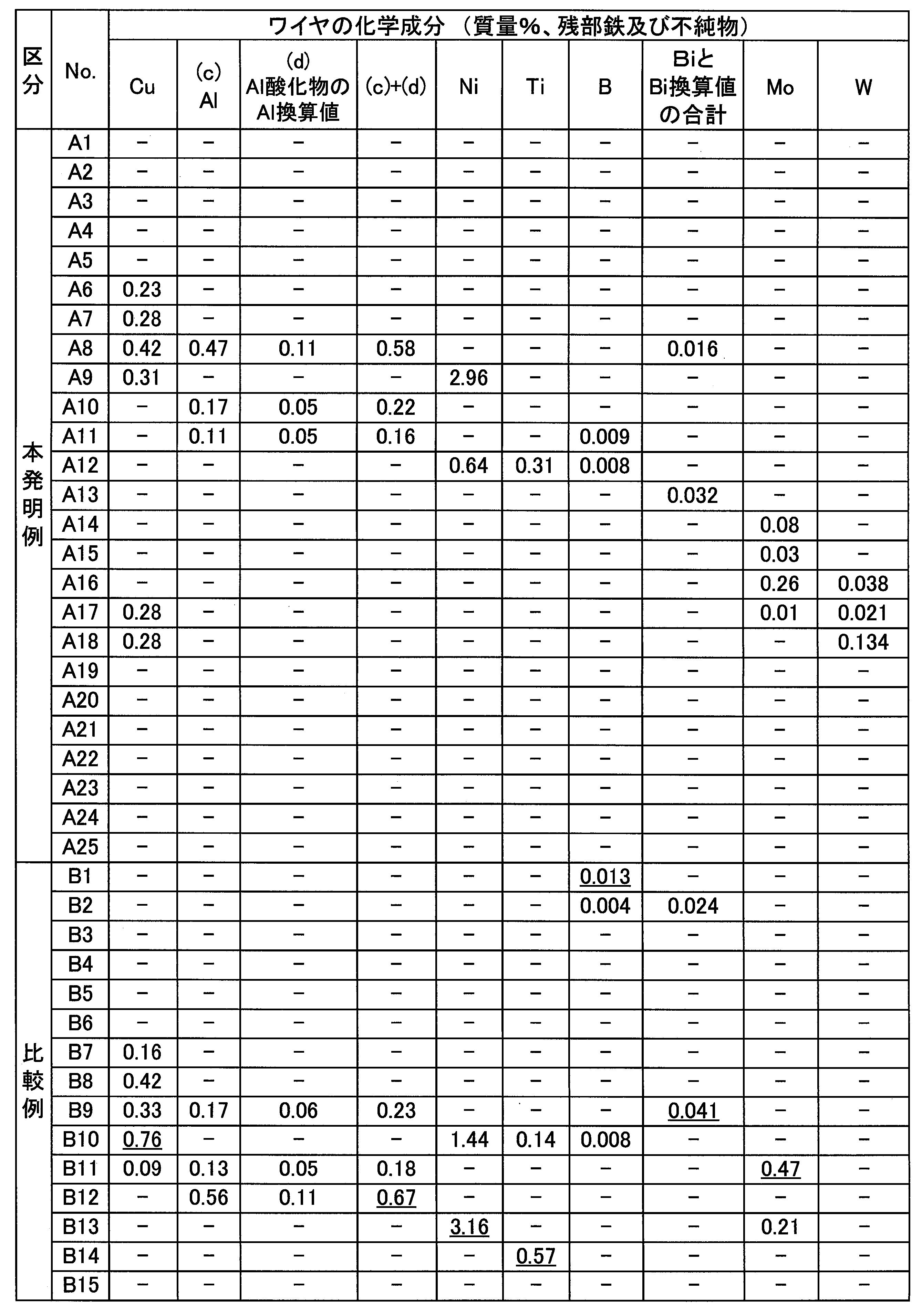

ビード形状の調査は、すみ肉溶接部の目視により実施した。ビード表面が平坦であるか、ふくらみが大きすぎないかを確認し、ビード形状の膨らみが大きすぎる場合を、ビード形状「不良」と判定した。また、立向上進及び上向姿勢溶接においては、溶接中に溶融金属が垂れてビードが形成されない場合も「不良」と判定した。
スパッタ発生量の評価では、溶接中に飛散するスパッタを捕集し、スパッタの質量を測定した。スパッタ発生量は、1分間の時間あたりのスパッタ質量が1.5g以上の場合を「多い」とし、1.5g未満の場合を「少ない」とした。
スラグ剥離性は、たがねによる打撃によらずスラグが剥離した場合を「非常に良好」とし、(たがねによる打撃なしではスラグが剥離せず)たがねによる打撃によりスラグが剥離した場合を「良好」とし、たがねによる打撃の後にもビード上にスラグが残留した場合を「不良」と判定した。

衝撃試験温度は0℃とした。ただし、Ni、Ti、及びBの1種以上を添加したワイヤから得られた溶着金属についてのみ、0℃及び-40℃での衝撃試験を実施した。
その後、得られた腐食試験片5をSAE(Society of Automotive Engineers) J2334試験に従い、耐食性を評価した。
SAE J2334試験の80サイクル後に、各試験片の塗膜剥離・膨れ面積率を計測した。また、実構造物の長期にわたる塗装耐食性能を反映する試験として塗膜密着性の評価を行った。クロスカットを対角線とする長方形に相当する領域の全面に対し、長方形の長辺長さ100mmに切りだした幅20mmの透明付着テープをお互いに重ならないように2列貼付け、テープ付着後5分以内に60°に近い角度にて4.0~8.0秒で引き離した。テープによる引き剥がし操作にて剥離した塗膜面積を、SAE J2334試験の80サイクル直後に残存していた塗膜面積にて除すことでテープ剥離率を求めた。その後、表面の残存塗膜と生成した錆層を除去し、塗装被膜疵部の腐食深さを測定後、平均腐食深さを算出した。
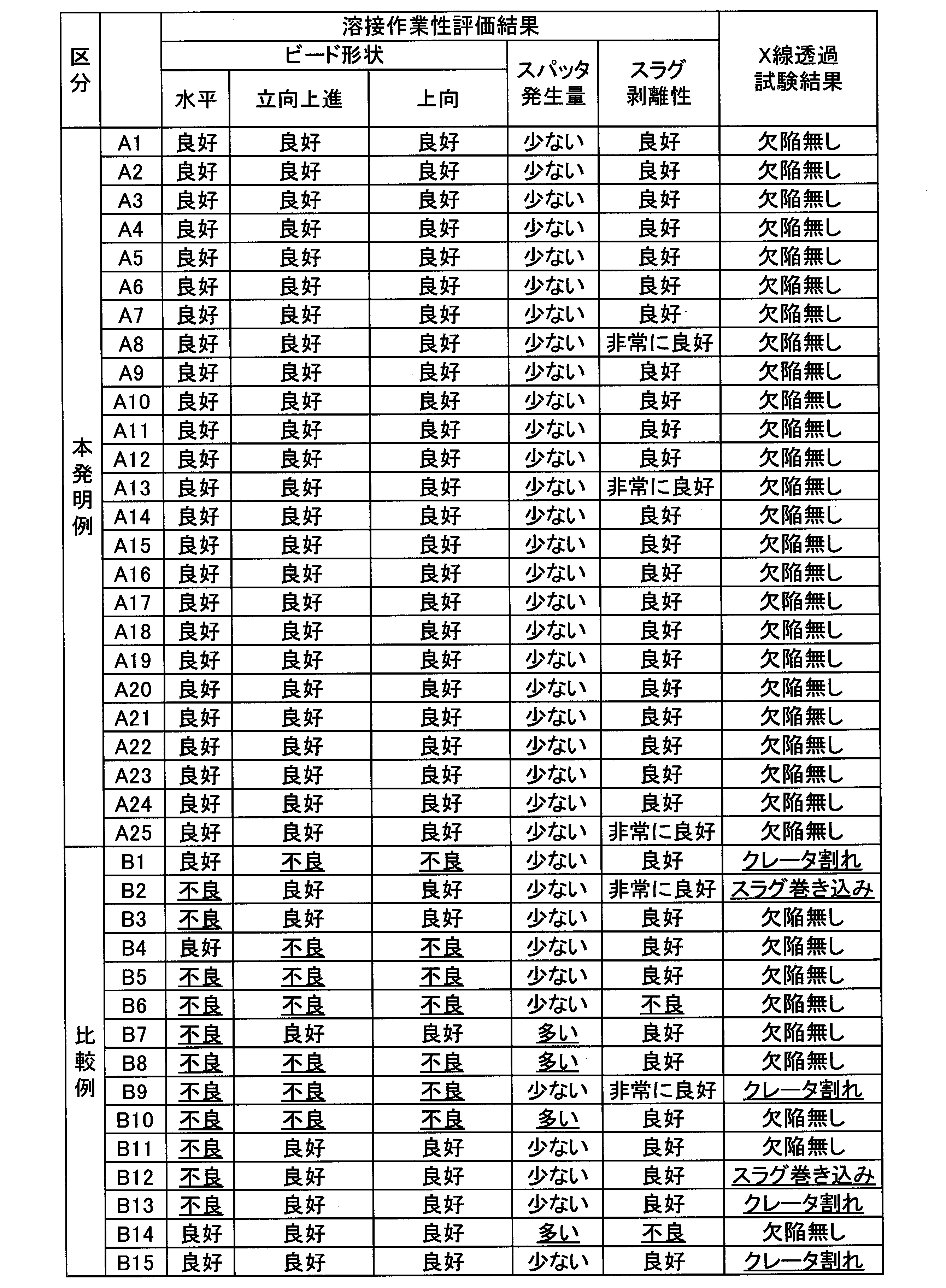
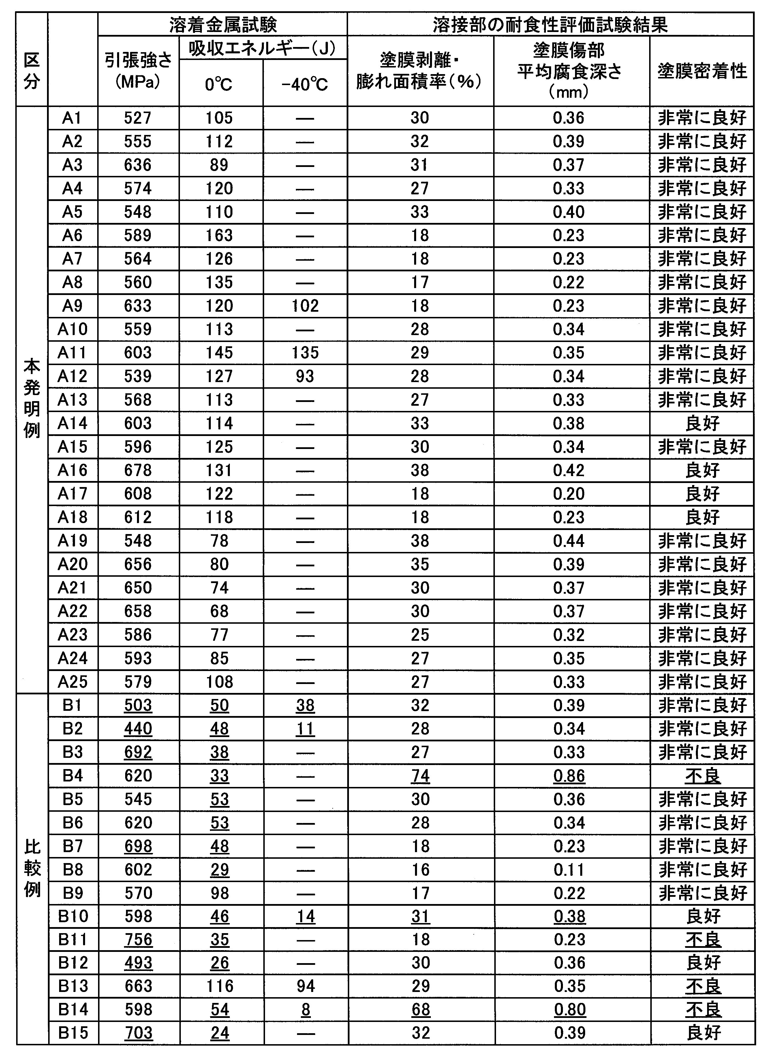
本発明例であるワイヤ記号A1~A25は、本発明例で規定した各成分範囲内であるので、水平、立向上進及び上向の各姿勢のすみ肉溶接においてビード形状が良好で、スラグ剥離性及びスパッタ発生量が少なく、X線透過試験で欠陥が無く、溶着金属の引張強さ及び吸収エネルギーが良好で、塗装剥離・膨れ面積率は全て50%未満、かつ塗装傷部腐食深さは、全て0.5mm未満であり、極めて満足な結果であった。
ワイヤ記号B2は、TiO2換算値が大きいので、水平すみ肉溶接でビード形状が不良となり、X線透過試験で、スラグ巻き込みが生じた。またワイヤ記号B2は、C量が少ないので、溶着金属の引張強さ及び吸収エネルギーが低値であった。
ワイヤ記号B4は、SiO2換算値が大きいので、立向上進及び上向のすみ肉溶接でメタル垂れが生じて平滑なビードが得られなかった。またワイヤ記号B4は、溶着金属の吸収エネルギーが低値であった。さらにワイヤ記号B4は、Sn量が少ないので、溶着金属の塗膜剥離・膨れ面積率が大きく、塗膜傷部の平均腐食深さも深かった。
ワイヤ記号B6は、ZrO2換算値が大きいので、評価した全ての姿勢のすみ肉溶接においてビード形状が不良であった。またワイヤ記号B6は、Mg量が少ないので、溶着金属の吸収エネルギーが低値であった。
ワイヤ記号B8は、Mg量が多いので、評価した全ての姿勢のすみ肉溶接においてビード形状が不良で、スパッタ発生量が多かった。またワイヤ記号B8は、Sn量が多いので、溶着金属の吸収エネルギーが低値であった。
ワイヤ記号B9は、Na2O換算値とK2O換算値の合計が大きいので、評価した全ての姿勢のすみ肉溶接においてビード形状が不良であった。またワイヤ記号B9は、Bi及びBi酸化物のBi換算値の合計が大きいので、クレータ割れが生じた。
ワイヤ記号B11は、F換算値が小さいので、水平すみ肉溶接でビード形状が不良であった。またワイヤ記号B11は、Mo量が多いので、溶着金属の引張強さが高く、吸収エネルギーが低値であった。さらにワイヤ番号B11は、指数Xが不足した(即ちSn+Sb>Mo+Wを満たさなかった)ので、塗膜密着性が不良であった。
ワイヤ記号B12は、C量が少ないので、溶着金属の引張強さ及び吸収エネルギーが低値であった。またワイヤ記号B12は、Al及びAl2O3のAl換算値の合計が大きいので、水平すみ肉溶接でビード形状が不良となり、X線透過試験で、スラグ巻き込みが生じた。
ワイヤ記号B14は、Sn量が少ないので、溶着金属の塗膜剥離・膨れ面積率が大きく、塗膜傷部の平均腐食深さも深かった。またワイヤ記号B14は、Ti量が多いので、スパッタが多く、スラグ剥離性が不良であった。さらにワイヤ記号B14は、溶着金属の吸収エネルギーが低値であった。
ワイヤ記号B15は、C量が多いので、溶着金属の引張強さが高く、吸収エネルギーが低値であった。またワイヤ記号B15は、クレータ割れが生じた。
2 溶着金属
3 腐食試験片の採取位置
4 クロスカット
5 腐食試験片
10 フラックス入りワイヤ
11 鋼製外皮
12 フラックス
13 鋼板
14 継ぎ目
15 溶接部
Claims (8)
- 鋼製外皮の内部にフラックスが充填されたフラックス入りワイヤの製造方法であって、
鋼板を円筒形に成形しながら、前記鋼板の内部にフラックスを充填する工程と、
前記鋼板の両端を接合して鋼管とする工程と、
前記鋼管に圧延及び焼鈍を施して、前記フラックス入りワイヤを得る工程と、を備え、
前記フラックス入りワイヤの化学組成が、前記フラックス入りワイヤの全質量に対する質量%で、
C:0.03~0.12%、
Si:0.20~0.85%、
Mn:1.50~3.20%、
P:0.020%以下、
S:0.020%以下、
Cu:0~0.70%、
Sn:0.05~0.40%、
Mg:0.05~0.70%、
Ti酸化物:TiO2換算値で4.60~7.00%、
Si酸化物:SiO2換算値で0.20~0.90%、
Zr酸化物:ZrO2換算値で0.10~0.70%、
Ni:0~3.00%、
Ti:0~0.50%、
B:0~0.010%、
Mo:0~0.40%、
W:0~0.200%、
Cr:0~0.500%、
Nb:0~0.300%、
V:0~0.300%、
N:0~0.008%、
Ca:0~0.0050%、
REM:0~0.0050%、
Sb:0~0.005%、
Fe酸化物:FeO換算値で0~2.50%、
Al及びAl酸化物の合計:Al換算値で合計0~0.60%、
Bi及びBi酸化物の合計:Bi換算値で合計0~0.035%、
Na化合物及びK化合物:Na2O換算値及びK2O換算値の合計で0.05~0.40%、
弗素化合物:F換算値で0.02~0.25%、
残部:Fe及び不純物であり、
Sn含有量、Sb含有量、W含有量、及びMo含有量が以下の式1を満たす
ことを特徴とするフラックス入りワイヤの製造方法。
Sn+Sb>Mo+W :式1
ただし、前記式1における元素記号は、各元素記号に係る元素の含有量を、前記フラックス入りワイヤの前記全質量に対する質量%で示すものである。 - 前記フラックス入りワイヤの化学組成が、前記フラックス入りワイヤの前記全質量に対する質量%で、
W:0~0.010%、
Mo:0~0.04%
であることを特徴とする請求項1に記載のフラックス入りワイヤの製造方法。 - 前記フラックス入りワイヤの化学組成が、前記フラックス入りワイヤの前記全質量に対する質量%で、
Cu:0.05~0.70%、
であることを特徴とする請求項1又は2に記載のフラックス入りワイヤの製造方法。 - 前記フラックス入りワイヤの化学組成が、前記フラックス入りワイヤの前記全質量に対する質量%で、少なくとも下記のいずれかひとつを満たすことを特徴とする請求項1~3のいずれか一項に記載のフラックス入りワイヤの製造方法。
Ni:0.10~3.00%
Ti:0.03~0.50%
B:0.002~0.010% - 前記接合がかしめであることを特徴とする請求項1~4のいずれか一項に記載のフラックス入りワイヤの製造方法。
- 前記接合が溶接であることを特徴とする請求項1~4のいずれか一項に記載のフラックス入りワイヤの製造方法。
- 請求項1~6のいずれか一項に記載のフラックス入りワイヤの製造方法によって製造されるフラックス入りワイヤ。
- 請求項1~6のいずれか一項に記載のフラックス入りワイヤの製造方法によって製造されるフラックス入りワイヤを用いて溶接する工程を備える溶接継手の製造方法。
Priority Applications (6)
| Application Number | Priority Date | Filing Date | Title |
|---|---|---|---|
| PCT/JP2018/012912 WO2019186811A1 (ja) | 2018-03-28 | 2018-03-28 | フラックス入りワイヤの製造方法、フラックス入りワイヤ、及び溶接継手の製造方法 |
| JP2018533266A JP6432714B1 (ja) | 2018-03-28 | 2018-03-28 | フラックス入りワイヤの製造方法、フラックス入りワイヤ、及び溶接継手の製造方法 |
| CN201880090894.4A CN111819029B (zh) | 2018-03-28 | 2018-03-28 | 药芯焊丝的制造方法、药芯焊丝以及焊接接头的制造方法 |
| KR1020207025432A KR102272173B1 (ko) | 2018-03-28 | 2018-03-28 | 플럭스 내포 와이어의 제조 방법, 플럭스 내포 와이어 및 용접 이음의 제조 방법 |
| EP18913159.2A EP3778112B1 (en) | 2018-03-28 | 2018-03-28 | Method for manufacturing flux-cored wire, flux-cored wire and method for manufacturing welded joint |
| AU2018416187A AU2018416187A1 (en) | 2018-03-28 | 2018-03-28 | Method for manufacturing flux-cored wire, flux-cored wire and method for manufacturing welded joint |
Applications Claiming Priority (1)
| Application Number | Priority Date | Filing Date | Title |
|---|---|---|---|
| PCT/JP2018/012912 WO2019186811A1 (ja) | 2018-03-28 | 2018-03-28 | フラックス入りワイヤの製造方法、フラックス入りワイヤ、及び溶接継手の製造方法 |
Publications (1)
| Publication Number | Publication Date |
|---|---|
| WO2019186811A1 true WO2019186811A1 (ja) | 2019-10-03 |
Family
ID=64560776
Family Applications (1)
| Application Number | Title | Priority Date | Filing Date |
|---|---|---|---|
| PCT/JP2018/012912 WO2019186811A1 (ja) | 2018-03-28 | 2018-03-28 | フラックス入りワイヤの製造方法、フラックス入りワイヤ、及び溶接継手の製造方法 |
Country Status (6)
| Country | Link |
|---|---|
| EP (1) | EP3778112B1 (ja) |
| JP (1) | JP6432714B1 (ja) |
| KR (1) | KR102272173B1 (ja) |
| CN (1) | CN111819029B (ja) |
| AU (1) | AU2018416187A1 (ja) |
| WO (1) | WO2019186811A1 (ja) |
Cited By (1)
| Publication number | Priority date | Publication date | Assignee | Title |
|---|---|---|---|---|
| CN115743687A (zh) * | 2023-01-10 | 2023-03-07 | 昆明金方金属制品有限公司 | 一种镀铜焊丝生产装置 |
Families Citing this family (2)
| Publication number | Priority date | Publication date | Assignee | Title |
|---|---|---|---|---|
| CN112760462A (zh) * | 2020-12-17 | 2021-05-07 | 包头钢铁(集团)有限责任公司 | 一种药芯焊丝用钢的制备方法 |
| JP2022121317A (ja) * | 2021-02-08 | 2022-08-19 | 株式会社神戸製鋼所 | ガスシールドアーク溶接用フラックス入りワイヤ |
Citations (8)
| Publication number | Priority date | Publication date | Assignee | Title |
|---|---|---|---|---|
| JPS58199693A (ja) * | 1982-05-17 | 1983-11-21 | Kobe Steel Ltd | フラツクス入りワイヤの製造方法 |
| JP2000288781A (ja) | 1999-04-09 | 2000-10-17 | Nippon Steel Corp | Cu−Ni−Ti系高耐候性鋼用フラックス入りワイヤ |
| JP2007262555A (ja) | 2006-03-30 | 2007-10-11 | Sumitomo Metal Ind Ltd | 石炭・鉱石運搬船ホールド用耐食性鋼材 |
| JP2008163374A (ja) | 2006-12-27 | 2008-07-17 | Sumitomo Metal Ind Ltd | 橋梁用鋼材 |
| JP2011020154A (ja) * | 2009-07-16 | 2011-02-03 | Nippon Steel Corp | ガスシールド溶接用フラックス入りワイヤ |
| JP2013151001A (ja) | 2012-01-25 | 2013-08-08 | Nippon Steel & Sumikin Welding Co Ltd | 耐候性鋼用ガスシールドアーク溶接用フラックス入りワイヤ |
| JP2013226577A (ja) * | 2012-04-25 | 2013-11-07 | Nippon Steel & Sumikin Welding Co Ltd | 原油油槽鋼のガスシールドアーク溶接用フラックス入りワイヤ |
| JP2018047486A (ja) * | 2016-09-21 | 2018-03-29 | 新日鐵住金株式会社 | 耐食鋼の水平すみ肉ガスシールドアーク溶接用フラックス入りワイヤ |
Family Cites Families (7)
| Publication number | Priority date | Publication date | Assignee | Title |
|---|---|---|---|---|
| JPH0723518B2 (ja) * | 1989-09-11 | 1995-03-15 | 株式会社神戸製鋼所 | 抵抗溶接用電極材料 |
| CN100515655C (zh) * | 2007-08-09 | 2009-07-22 | 武汉铁锚焊接材料股份有限公司 | 一种二氧化碳气体保护焊用低合金钢药芯焊丝 |
| JP5356142B2 (ja) * | 2009-07-28 | 2013-12-04 | 日鐵住金溶接工業株式会社 | ガスシールドアーク溶接方法 |
| JP5416605B2 (ja) * | 2010-02-02 | 2014-02-12 | 株式会社神戸製鋼所 | フラックス入りワイヤ |
| WO2015068261A1 (ja) * | 2013-11-08 | 2015-05-14 | 新日鐵住金株式会社 | 溶接継手の製造方法 |
| JP6250475B2 (ja) * | 2014-05-14 | 2017-12-20 | 株式会社神戸製鋼所 | Ni基合金フラックス入りワイヤ |
| JP6658424B2 (ja) * | 2016-09-21 | 2020-03-04 | 日本製鉄株式会社 | 耐食鋼のガスシールドアーク溶接用フラックス入りワイヤ |
-
2018
- 2018-03-28 AU AU2018416187A patent/AU2018416187A1/en not_active Abandoned
- 2018-03-28 WO PCT/JP2018/012912 patent/WO2019186811A1/ja unknown
- 2018-03-28 EP EP18913159.2A patent/EP3778112B1/en active Active
- 2018-03-28 CN CN201880090894.4A patent/CN111819029B/zh active Active
- 2018-03-28 JP JP2018533266A patent/JP6432714B1/ja active Active
- 2018-03-28 KR KR1020207025432A patent/KR102272173B1/ko active IP Right Grant
Patent Citations (8)
| Publication number | Priority date | Publication date | Assignee | Title |
|---|---|---|---|---|
| JPS58199693A (ja) * | 1982-05-17 | 1983-11-21 | Kobe Steel Ltd | フラツクス入りワイヤの製造方法 |
| JP2000288781A (ja) | 1999-04-09 | 2000-10-17 | Nippon Steel Corp | Cu−Ni−Ti系高耐候性鋼用フラックス入りワイヤ |
| JP2007262555A (ja) | 2006-03-30 | 2007-10-11 | Sumitomo Metal Ind Ltd | 石炭・鉱石運搬船ホールド用耐食性鋼材 |
| JP2008163374A (ja) | 2006-12-27 | 2008-07-17 | Sumitomo Metal Ind Ltd | 橋梁用鋼材 |
| JP2011020154A (ja) * | 2009-07-16 | 2011-02-03 | Nippon Steel Corp | ガスシールド溶接用フラックス入りワイヤ |
| JP2013151001A (ja) | 2012-01-25 | 2013-08-08 | Nippon Steel & Sumikin Welding Co Ltd | 耐候性鋼用ガスシールドアーク溶接用フラックス入りワイヤ |
| JP2013226577A (ja) * | 2012-04-25 | 2013-11-07 | Nippon Steel & Sumikin Welding Co Ltd | 原油油槽鋼のガスシールドアーク溶接用フラックス入りワイヤ |
| JP2018047486A (ja) * | 2016-09-21 | 2018-03-29 | 新日鐵住金株式会社 | 耐食鋼の水平すみ肉ガスシールドアーク溶接用フラックス入りワイヤ |
Non-Patent Citations (1)
| Title |
|---|
| See also references of EP3778112A4 |
Cited By (1)
| Publication number | Priority date | Publication date | Assignee | Title |
|---|---|---|---|---|
| CN115743687A (zh) * | 2023-01-10 | 2023-03-07 | 昆明金方金属制品有限公司 | 一种镀铜焊丝生产装置 |
Also Published As
| Publication number | Publication date |
|---|---|
| EP3778112B1 (en) | 2022-07-13 |
| EP3778112A1 (en) | 2021-02-17 |
| KR20200108093A (ko) | 2020-09-16 |
| CN111819029B (zh) | 2021-09-21 |
| CN111819029A (zh) | 2020-10-23 |
| EP3778112A4 (en) | 2021-10-27 |
| AU2018416187A1 (en) | 2020-08-06 |
| KR102272173B1 (ko) | 2021-07-05 |
| JP6432714B1 (ja) | 2018-12-05 |
| JPWO2019186811A1 (ja) | 2020-04-30 |
Similar Documents
| Publication | Publication Date | Title |
|---|---|---|
| JP5704573B2 (ja) | 原油油槽鋼のガスシールドアーク溶接用フラックス入りワイヤ | |
| JP5194586B2 (ja) | 亜鉛めっき鋼板溶接用ステンレス鋼フラックス入り溶接ワイヤ | |
| KR101012199B1 (ko) | 아연 기재 합금으로 코팅한 강판을 용접하기 위한스테인레스강 기재 용접 금속으로 이루어진 용접 접합부 | |
| JP5717688B2 (ja) | 原油油槽鋼の水平すみ肉ガスシールドアーク溶接用フラックス入りワイヤ | |
| JP5384312B2 (ja) | 耐候性鋼用ガスシールドアーク溶接用フラックス入りワイヤ | |
| JP6432714B1 (ja) | フラックス入りワイヤの製造方法、フラックス入りワイヤ、及び溶接継手の製造方法 | |
| JP4303655B2 (ja) | 溶接部の耐食性および耐亜鉛脆化割れ性に優れた亜鉛めっき鋼板の溶接方法 | |
| JP4980294B2 (ja) | 亜鉛めっき鋼板用被覆アーク溶接棒 | |
| JP6658424B2 (ja) | 耐食鋼のガスシールドアーク溶接用フラックス入りワイヤ | |
| JP6658423B2 (ja) | 耐食鋼の水平すみ肉ガスシールドアーク溶接用フラックス入りワイヤ | |
| JP4838100B2 (ja) | 耐候性鋼用水平すみガスシールドアーク溶接用フラックス入りワイヤ | |
| JP6939508B2 (ja) | 耐食鋼のガスシールドアーク溶接用フラックス入りワイヤ、及び溶接継手の製造方法 | |
| JP6432715B1 (ja) | フラックス入りワイヤの製造方法、フラックス入りワイヤ、及び溶接継手の製造方法 | |
| JP2675894B2 (ja) | 高強度オーステナイト系ステンレス鋼溶接用フラックス入りワイヤ | |
| JP7308657B2 (ja) | 原油油槽鋼の低水素系被覆アーク溶接棒 | |
| JP7304829B2 (ja) | 亜鉛めっき鋼板溶接用フラックス入りワイヤ | |
| JP6463234B2 (ja) | 原油油槽鋼の2電極水平すみ肉ガスシールドアーク溶接用フラックス入りワイヤ | |
| JP2001300769A (ja) | 海岸高耐候性鋼用低水素系被覆ア−ク溶接棒 | |
| JP2003112287A (ja) | 海浜耐候性鋼溶接用フラックス入りワイヤ | |
| JPH0452190B2 (ja) |
Legal Events
| Date | Code | Title | Description |
|---|---|---|---|
| ENP | Entry into the national phase |
Ref document number: 2018533266 Country of ref document: JP Kind code of ref document: A |
|
| 121 | Ep: the epo has been informed by wipo that ep was designated in this application |
Ref document number: 18913159 Country of ref document: EP Kind code of ref document: A1 |
|
| ENP | Entry into the national phase |
Ref document number: 2018416187 Country of ref document: AU Date of ref document: 20180328 Kind code of ref document: A |
|
| ENP | Entry into the national phase |
Ref document number: 20207025432 Country of ref document: KR Kind code of ref document: A |
|
| NENP | Non-entry into the national phase |
Ref country code: DE |
|
| ENP | Entry into the national phase |
Ref document number: 2018913159 Country of ref document: EP Effective date: 20201028 |