WO2019155901A1 - 二酸化炭素製造システム - Google Patents
二酸化炭素製造システム Download PDFInfo
- Publication number
- WO2019155901A1 WO2019155901A1 PCT/JP2019/002372 JP2019002372W WO2019155901A1 WO 2019155901 A1 WO2019155901 A1 WO 2019155901A1 JP 2019002372 W JP2019002372 W JP 2019002372W WO 2019155901 A1 WO2019155901 A1 WO 2019155901A1
- Authority
- WO
- WIPO (PCT)
- Prior art keywords
- carbon dioxide
- gas
- fuel gas
- production system
- fuel
- Prior art date
- Legal status (The legal status is an assumption and is not a legal conclusion. Google has not performed a legal analysis and makes no representation as to the accuracy of the status listed.)
- Ceased
Links
Images


Classifications
-
- C—CHEMISTRY; METALLURGY
- C01—INORGANIC CHEMISTRY
- C01B—NON-METALLIC ELEMENTS; COMPOUNDS THEREOF; METALLOIDS OR COMPOUNDS THEREOF NOT COVERED BY SUBCLASS C01C
- C01B32/00—Carbon; Compounds thereof
- C01B32/50—Carbon dioxide
-
- B—PERFORMING OPERATIONS; TRANSPORTING
- B01—PHYSICAL OR CHEMICAL PROCESSES OR APPARATUS IN GENERAL
- B01D—SEPARATION
- B01D53/00—Separation of gases or vapours; Recovering vapours of volatile solvents from gases; Chemical or biological purification of waste gases, e.g. engine exhaust gases, smoke, fumes, flue gases, aerosols
- B01D53/22—Separation of gases or vapours; Recovering vapours of volatile solvents from gases; Chemical or biological purification of waste gases, e.g. engine exhaust gases, smoke, fumes, flue gases, aerosols by diffusion
-
- H—ELECTRICITY
- H01—ELECTRIC ELEMENTS
- H01M—PROCESSES OR MEANS, e.g. BATTERIES, FOR THE DIRECT CONVERSION OF CHEMICAL ENERGY INTO ELECTRICAL ENERGY
- H01M8/00—Fuel cells; Manufacture thereof
- H01M8/04—Auxiliary arrangements, e.g. for control of pressure or for circulation of fluids
- H01M8/04007—Auxiliary arrangements, e.g. for control of pressure or for circulation of fluids related to heat exchange
- H01M8/04014—Heat exchange using gaseous fluids; Heat exchange by combustion of reactants
- H01M8/04022—Heating by combustion
-
- H—ELECTRICITY
- H01—ELECTRIC ELEMENTS
- H01M—PROCESSES OR MEANS, e.g. BATTERIES, FOR THE DIRECT CONVERSION OF CHEMICAL ENERGY INTO ELECTRICAL ENERGY
- H01M8/00—Fuel cells; Manufacture thereof
- H01M8/04—Auxiliary arrangements, e.g. for control of pressure or for circulation of fluids
- H01M8/04082—Arrangements for control of reactant parameters, e.g. pressure or concentration
- H01M8/04089—Arrangements for control of reactant parameters, e.g. pressure or concentration of gaseous reactants
- H01M8/04119—Arrangements for control of reactant parameters, e.g. pressure or concentration of gaseous reactants with simultaneous supply or evacuation of electrolyte; Humidifying or dehumidifying
- H01M8/04156—Arrangements for control of reactant parameters, e.g. pressure or concentration of gaseous reactants with simultaneous supply or evacuation of electrolyte; Humidifying or dehumidifying with product water removal
-
- H—ELECTRICITY
- H01—ELECTRIC ELEMENTS
- H01M—PROCESSES OR MEANS, e.g. BATTERIES, FOR THE DIRECT CONVERSION OF CHEMICAL ENERGY INTO ELECTRICAL ENERGY
- H01M8/00—Fuel cells; Manufacture thereof
- H01M8/04—Auxiliary arrangements, e.g. for control of pressure or for circulation of fluids
- H01M8/04291—Arrangements for managing water in solid electrolyte fuel cell systems
-
- H—ELECTRICITY
- H01—ELECTRIC ELEMENTS
- H01M—PROCESSES OR MEANS, e.g. BATTERIES, FOR THE DIRECT CONVERSION OF CHEMICAL ENERGY INTO ELECTRICAL ENERGY
- H01M8/00—Fuel cells; Manufacture thereof
- H01M8/04—Auxiliary arrangements, e.g. for control of pressure or for circulation of fluids
- H01M8/04298—Processes for controlling fuel cells or fuel cell systems
- H01M8/04313—Processes for controlling fuel cells or fuel cell systems characterised by the detection or assessment of variables; characterised by the detection or assessment of failure or abnormal function
- H01M8/0438—Pressure; Ambient pressure; Flow
- H01M8/04425—Pressure; Ambient pressure; Flow at auxiliary devices, e.g. reformers, compressors, burners
-
- H—ELECTRICITY
- H01—ELECTRIC ELEMENTS
- H01M—PROCESSES OR MEANS, e.g. BATTERIES, FOR THE DIRECT CONVERSION OF CHEMICAL ENERGY INTO ELECTRICAL ENERGY
- H01M8/00—Fuel cells; Manufacture thereof
- H01M8/04—Auxiliary arrangements, e.g. for control of pressure or for circulation of fluids
- H01M8/04298—Processes for controlling fuel cells or fuel cell systems
- H01M8/04313—Processes for controlling fuel cells or fuel cell systems characterised by the detection or assessment of variables; characterised by the detection or assessment of failure or abnormal function
- H01M8/0444—Concentration; Density
-
- H—ELECTRICITY
- H01—ELECTRIC ELEMENTS
- H01M—PROCESSES OR MEANS, e.g. BATTERIES, FOR THE DIRECT CONVERSION OF CHEMICAL ENERGY INTO ELECTRICAL ENERGY
- H01M8/00—Fuel cells; Manufacture thereof
- H01M8/04—Auxiliary arrangements, e.g. for control of pressure or for circulation of fluids
- H01M8/04298—Processes for controlling fuel cells or fuel cell systems
- H01M8/04694—Processes for controlling fuel cells or fuel cell systems characterised by variables to be controlled
- H01M8/04746—Pressure; Flow
- H01M8/04753—Pressure; Flow of fuel cell reactants
-
- H—ELECTRICITY
- H01—ELECTRIC ELEMENTS
- H01M—PROCESSES OR MEANS, e.g. BATTERIES, FOR THE DIRECT CONVERSION OF CHEMICAL ENERGY INTO ELECTRICAL ENERGY
- H01M8/00—Fuel cells; Manufacture thereof
- H01M8/04—Auxiliary arrangements, e.g. for control of pressure or for circulation of fluids
- H01M8/04298—Processes for controlling fuel cells or fuel cell systems
- H01M8/04694—Processes for controlling fuel cells or fuel cell systems characterised by variables to be controlled
- H01M8/04746—Pressure; Flow
- H01M8/04776—Pressure; Flow at auxiliary devices, e.g. reformer, compressor, burner
-
- H—ELECTRICITY
- H01—ELECTRIC ELEMENTS
- H01M—PROCESSES OR MEANS, e.g. BATTERIES, FOR THE DIRECT CONVERSION OF CHEMICAL ENERGY INTO ELECTRICAL ENERGY
- H01M8/00—Fuel cells; Manufacture thereof
- H01M8/04—Auxiliary arrangements, e.g. for control of pressure or for circulation of fluids
- H01M8/04298—Processes for controlling fuel cells or fuel cell systems
- H01M8/04694—Processes for controlling fuel cells or fuel cell systems characterised by variables to be controlled
- H01M8/04791—Concentration; Density
-
- H—ELECTRICITY
- H01—ELECTRIC ELEMENTS
- H01M—PROCESSES OR MEANS, e.g. BATTERIES, FOR THE DIRECT CONVERSION OF CHEMICAL ENERGY INTO ELECTRICAL ENERGY
- H01M8/00—Fuel cells; Manufacture thereof
- H01M8/04—Auxiliary arrangements, e.g. for control of pressure or for circulation of fluids
- H01M8/04298—Processes for controlling fuel cells or fuel cell systems
- H01M8/04694—Processes for controlling fuel cells or fuel cell systems characterised by variables to be controlled
- H01M8/04858—Electric variables
- H01M8/04925—Power, energy, capacity or load
- H01M8/0494—Power, energy, capacity or load of fuel cell stacks
-
- H—ELECTRICITY
- H01—ELECTRIC ELEMENTS
- H01M—PROCESSES OR MEANS, e.g. BATTERIES, FOR THE DIRECT CONVERSION OF CHEMICAL ENERGY INTO ELECTRICAL ENERGY
- H01M8/00—Fuel cells; Manufacture thereof
- H01M8/06—Combination of fuel cells with means for production of reactants or for treatment of residues
- H01M8/0606—Combination of fuel cells with means for production of reactants or for treatment of residues with means for production of gaseous reactants
- H01M8/0612—Combination of fuel cells with means for production of reactants or for treatment of residues with means for production of gaseous reactants from carbon-containing material
- H01M8/0618—Reforming processes, e.g. autothermal, partial oxidation or steam reforming
-
- H—ELECTRICITY
- H01—ELECTRIC ELEMENTS
- H01M—PROCESSES OR MEANS, e.g. BATTERIES, FOR THE DIRECT CONVERSION OF CHEMICAL ENERGY INTO ELECTRICAL ENERGY
- H01M8/00—Fuel cells; Manufacture thereof
- H01M8/06—Combination of fuel cells with means for production of reactants or for treatment of residues
- H01M8/0662—Treatment of gaseous reactants or gaseous residues, e.g. cleaning
- H01M8/0668—Removal of carbon monoxide or carbon dioxide
-
- H—ELECTRICITY
- H01—ELECTRIC ELEMENTS
- H01M—PROCESSES OR MEANS, e.g. BATTERIES, FOR THE DIRECT CONVERSION OF CHEMICAL ENERGY INTO ELECTRICAL ENERGY
- H01M8/00—Fuel cells; Manufacture thereof
- H01M8/06—Combination of fuel cells with means for production of reactants or for treatment of residues
- H01M8/0662—Treatment of gaseous reactants or gaseous residues, e.g. cleaning
- H01M8/0687—Reactant purification by the use of membranes or filters
-
- H—ELECTRICITY
- H01—ELECTRIC ELEMENTS
- H01M—PROCESSES OR MEANS, e.g. BATTERIES, FOR THE DIRECT CONVERSION OF CHEMICAL ENERGY INTO ELECTRICAL ENERGY
- H01M8/00—Fuel cells; Manufacture thereof
- H01M8/24—Grouping of fuel cells, e.g. stacking of fuel cells
- H01M8/249—Grouping of fuel cells, e.g. stacking of fuel cells comprising two or more groupings of fuel cells, e.g. modular assemblies
-
- B—PERFORMING OPERATIONS; TRANSPORTING
- B01—PHYSICAL OR CHEMICAL PROCESSES OR APPARATUS IN GENERAL
- B01D—SEPARATION
- B01D2256/00—Main component in the product gas stream after treatment
- B01D2256/22—Carbon dioxide
-
- B—PERFORMING OPERATIONS; TRANSPORTING
- B01—PHYSICAL OR CHEMICAL PROCESSES OR APPARATUS IN GENERAL
- B01D—SEPARATION
- B01D53/00—Separation of gases or vapours; Recovering vapours of volatile solvents from gases; Chemical or biological purification of waste gases, e.g. engine exhaust gases, smoke, fumes, flue gases, aerosols
- B01D53/02—Separation of gases or vapours; Recovering vapours of volatile solvents from gases; Chemical or biological purification of waste gases, e.g. engine exhaust gases, smoke, fumes, flue gases, aerosols by adsorption, e.g. preparative gas chromatography
- B01D53/04—Separation of gases or vapours; Recovering vapours of volatile solvents from gases; Chemical or biological purification of waste gases, e.g. engine exhaust gases, smoke, fumes, flue gases, aerosols by adsorption, e.g. preparative gas chromatography with stationary adsorbents
- B01D53/047—Pressure swing adsorption
-
- B—PERFORMING OPERATIONS; TRANSPORTING
- B01—PHYSICAL OR CHEMICAL PROCESSES OR APPARATUS IN GENERAL
- B01D—SEPARATION
- B01D53/00—Separation of gases or vapours; Recovering vapours of volatile solvents from gases; Chemical or biological purification of waste gases, e.g. engine exhaust gases, smoke, fumes, flue gases, aerosols
- B01D53/26—Drying gases or vapours
- B01D53/268—Drying gases or vapours by diffusion
-
- H—ELECTRICITY
- H01—ELECTRIC ELEMENTS
- H01M—PROCESSES OR MEANS, e.g. BATTERIES, FOR THE DIRECT CONVERSION OF CHEMICAL ENERGY INTO ELECTRICAL ENERGY
- H01M8/00—Fuel cells; Manufacture thereof
- H01M8/10—Fuel cells with solid electrolytes
- H01M8/12—Fuel cells with solid electrolytes operating at high temperature, e.g. with stabilised ZrO2 electrolyte
- H01M2008/1293—Fuel cells with solid oxide electrolytes
-
- H—ELECTRICITY
- H01—ELECTRIC ELEMENTS
- H01M—PROCESSES OR MEANS, e.g. BATTERIES, FOR THE DIRECT CONVERSION OF CHEMICAL ENERGY INTO ELECTRICAL ENERGY
- H01M8/00—Fuel cells; Manufacture thereof
- H01M8/24—Grouping of fuel cells, e.g. stacking of fuel cells
- H01M8/249—Grouping of fuel cells, e.g. stacking of fuel cells comprising two or more groupings of fuel cells, e.g. modular assemblies
- H01M8/2495—Grouping of fuel cells, e.g. stacking of fuel cells comprising two or more groupings of fuel cells, e.g. modular assemblies of fuel cells of different types
-
- Y—GENERAL TAGGING OF NEW TECHNOLOGICAL DEVELOPMENTS; GENERAL TAGGING OF CROSS-SECTIONAL TECHNOLOGIES SPANNING OVER SEVERAL SECTIONS OF THE IPC; TECHNICAL SUBJECTS COVERED BY FORMER USPC CROSS-REFERENCE ART COLLECTIONS [XRACs] AND DIGESTS
- Y02—TECHNOLOGIES OR APPLICATIONS FOR MITIGATION OR ADAPTATION AGAINST CLIMATE CHANGE
- Y02E—REDUCTION OF GREENHOUSE GAS [GHG] EMISSIONS, RELATED TO ENERGY GENERATION, TRANSMISSION OR DISTRIBUTION
- Y02E60/00—Enabling technologies; Technologies with a potential or indirect contribution to GHG emissions mitigation
- Y02E60/30—Hydrogen technology
- Y02E60/50—Fuel cells
-
- Y—GENERAL TAGGING OF NEW TECHNOLOGICAL DEVELOPMENTS; GENERAL TAGGING OF CROSS-SECTIONAL TECHNOLOGIES SPANNING OVER SEVERAL SECTIONS OF THE IPC; TECHNICAL SUBJECTS COVERED BY FORMER USPC CROSS-REFERENCE ART COLLECTIONS [XRACs] AND DIGESTS
- Y02—TECHNOLOGIES OR APPLICATIONS FOR MITIGATION OR ADAPTATION AGAINST CLIMATE CHANGE
- Y02P—CLIMATE CHANGE MITIGATION TECHNOLOGIES IN THE PRODUCTION OR PROCESSING OF GOODS
- Y02P20/00—Technologies relating to chemical industry
- Y02P20/151—Reduction of greenhouse gas [GHG] emissions, e.g. CO2
-
- Y—GENERAL TAGGING OF NEW TECHNOLOGICAL DEVELOPMENTS; GENERAL TAGGING OF CROSS-SECTIONAL TECHNOLOGIES SPANNING OVER SEVERAL SECTIONS OF THE IPC; TECHNICAL SUBJECTS COVERED BY FORMER USPC CROSS-REFERENCE ART COLLECTIONS [XRACs] AND DIGESTS
- Y02—TECHNOLOGIES OR APPLICATIONS FOR MITIGATION OR ADAPTATION AGAINST CLIMATE CHANGE
- Y02P—CLIMATE CHANGE MITIGATION TECHNOLOGIES IN THE PRODUCTION OR PROCESSING OF GOODS
- Y02P70/00—Climate change mitigation technologies in the production process for final industrial or consumer products
- Y02P70/50—Manufacturing or production processes characterised by the final manufactured product
Definitions
- the present invention relates to a carbon dioxide production system.
- carbon dioxide is generated. This carbon dioxide is also contained in the anode off gas discharged from the anode.
- the anode off gas is used as a regenerative fuel for power generation, the carbon dioxide is removed from the anode off gas.
- the anode off-gas is condensed to separate water vapor, the anode off-gas from which the water vapor has been separated is introduced into a carbon dioxide separator, and the carbon dioxide is separated and recovered by a separation membrane.
- Technology is disclosed.
- a high concentration of carbon dioxide can be easily recovered by separating and recovering carbon dioxide from the anode off gas of the fuel cell system having a higher carbon dioxide concentration than the combustion exhaust gas mixed with the cathode off gas.
- the regenerated fuel gas is efficiently reused for power generation, and ingenuity is required for the recovery of carbon dioxide.
- the present invention has been made in consideration of the above-described facts, and an object thereof is to easily separate carbon dioxide from the anode off-gas and to efficiently reuse the regenerated fuel gas for power generation.
- the carbon dioxide production system generates power from a fuel gas containing a carbon compound and supplied to a fuel electrode and an oxidant gas containing oxygen and supplied to an air electrode, and the fuel electrode A fuel cell from which the anode off-gas is discharged, a separation unit for separating the anode off-gas into a non-fuel gas containing at least carbon dioxide and water and a regenerated fuel gas, and a water separation unit for separating water from the non-fuel gas And a carbon dioxide recovery part that recovers carbon dioxide after water is separated by the water separation part.
- power generation in the fuel cell is performed by the fuel gas supplied to the fuel electrode and the oxidant gas supplied to the air electrode.
- the fuel gas contains a carbon compound, and an anode off-gas containing at least carbon dioxide and water is discharged from the fuel electrode.
- the fuel gas here is not particularly limited as long as it contains a carbon compound.
- the fuel gas may be a reformed gas obtained by reforming a hydrocarbon compound or a hydrocarbon compound itself. Carbon monoxide itself may be used.
- the separation unit separates the anode off gas into a non-fuel gas containing at least carbon dioxide and water and a regenerated fuel gas.
- the regenerated fuel gas can be maintained at a high temperature, so that the loss of heat energy can be reduced and the regenerated fuel gas can be efficiently used for power generation.
- the degree of freedom in selecting the separation means can be increased as compared with the case where only carbon dioxide is separated from the anode off gas.
- the non-fuel gas is separated in the water separation unit, and the non-fuel gas after the water is separated is recovered in the carbon dioxide recovery unit.
- water and carbon dioxide are the main components, so that water can be easily separated by condensation.
- the carbon dioxide production system includes a second fuel cell that generates electric power using the regenerated fuel gas delivered from the separation unit.
- power generation efficiency can be increased because power is generated by the second fuel cell using the regenerated fuel gas.
- the separation unit is partitioned into a non-permeation side and a permeation side by a separation membrane that allows the non-fuel gas to permeate, and the non-fuel gas is separated from the permeation side.
- a suction pump that sucks and sends the carbon dioxide to the carbon dioxide recovery unit is provided.
- permeation of the non-fuel gas to the permeation side can be promoted by performing suction with the suction pump.
- a carbon dioxide production system generates power from a fuel gas containing a carbon compound and supplied to a fuel electrode and an oxidant gas containing oxygen and supplied to an air electrode, and the fuel electrode A fuel cell from which anode off-gas is discharged, a separation unit that separates the anode off-gas into a non-fuel gas containing at least carbon dioxide and a regenerated fuel gas, and a non-fuel gas separated by the separation unit And a carbon dioxide adjusting unit that adjusts so that at least one of the concentration of carbon dioxide in the non-fuel gas and the flow rate of the non-fuel gas collected by the carbon dioxide collecting unit falls within a set range.
- power generation in the fuel cell is performed by the fuel gas supplied to the fuel electrode and the oxidant gas supplied to the air electrode.
- the fuel gas contains a carbon compound, and an anode off-gas containing at least carbon dioxide and water is discharged from the fuel electrode.
- the separation unit separates the anode off gas into a non-fuel gas containing at least carbon dioxide and a regenerated fuel gas. Then, at least one of the concentration of carbon dioxide in the non-fuel gas and the flow rate of the non-fuel gas recovered by the carbon dioxide recovery unit is adjusted by the carbon dioxide adjusting unit so as to be within the set range. Thereby, the carbon dioxide of the density
- a carbon dioxide production system includes a second fuel cell that generates electric power using the regenerated fuel gas delivered from the separation unit.
- power generation efficiency can be increased because power is generated by the second fuel cell using the regenerated fuel gas.
- the carbon dioxide production system is characterized in that the carbon dioxide adjusting unit adjusts the power generation amount in the fuel cell.
- the carbon dioxide concentration and the carbon dioxide flow rate in the anode off-gas change by adjusting the power generation amount in the fuel cell.
- the amount and concentration of carbon dioxide per hit can be adjusted.
- the carbon dioxide production system according to a seventh aspect of the present invention is characterized in that the carbon dioxide adjusting unit adjusts the power generation amount in the entire system.
- the carbon dioxide concentration and the carbon dioxide flow rate in the anode off-gas change by adjusting the power generation amount in the entire system, The amount and concentration of carbon dioxide can be adjusted.
- the separation unit separates the anode off-gas into a non-fuel gas containing at least carbon dioxide and water and a regenerated fuel gas, and water from the non-fuel gas.
- a water separation unit for separating the water.
- the regenerated fuel gas can be maintained at a high temperature, so that the regenerated fuel gas can be efficiently used for power generation.
- the choice of a separation means can be expanded compared with the case where only carbon dioxide is separated from the anode off gas.
- the non-fuel gas is separated in the water separation unit, and the non-fuel gas after the water is separated is recovered in the carbon dioxide recovery unit.
- water and carbon dioxide are the main components, so that the options of means for separating water can be expanded.
- the water separation unit removes water vapor from the non-fuel gas by condensation, and the carbon dioxide adjustment unit adjusts the amount of condensation in the water separation unit. It is characterized by doing.
- the concentration of carbon dioxide recovered by the carbon dioxide recovery unit can be adjusted by adjusting the amount of condensation in the water separation unit.
- the carbon dioxide production system has a pressure swing adsorption unit on the downstream side of the water separation unit, and the concentration adjusting unit adjusts adsorption conditions in the pressure swing adsorption unit, It is characterized by.
- the concentration of carbon dioxide recovered by the carbon dioxide recovery unit can be adjusted by adjusting the adsorption conditions in the pressure swing adsorption unit.
- the carbon dioxide production system is characterized in that the carbon dioxide adjusting unit adjusts the amount of the fuel gas delivered to the fuel electrode.
- the carbon dioxide concentration and the carbon dioxide flow rate in the anode off-gas are changed by adjusting the amount of the fuel gas delivered to the fuel electrode.
- the amount and concentration of carbon dioxide per hour to be recovered can be adjusted.
- a carbon dioxide production system includes a reformer that reforms a raw material gas to generate the fuel gas, and the carbon dioxide adjusting unit is a reformer that supplies the reformer. Adjusting the amount of quality water.
- the amount and concentration of carbon dioxide per hour recovered by the carbon dioxide recovery unit are adjusted by adjusting the amount of reforming water supplied to the reformer. be able to.
- the separation unit is partitioned into a non-permeation side and a permeation side by a separation membrane that allows the non-fuel gas to permeate, and the non-fuel gas is supplied from the permeation side.
- a suction pump that sucks and sends the carbon dioxide to the carbon dioxide recovery unit is provided.
- carbon dioxide can be recovered without lowering the concentration of carbon dioxide by lowering the pressure on the permeate side with a suction pump.
- the separation unit is partitioned into a non-permeation side and a permeation side by a separation membrane that allows the non-fuel gas to permeate, and the non-fuel gas is supplied from the permeation side.
- a suction pump for sucking and sending to the carbon dioxide recovery unit is provided, and the carbon dioxide adjustment unit adjusts a suction flow rate of the suction pump.
- the flow rate of carbon dioxide recovered by the carbon dioxide recovery unit can be adjusted by adjusting the suction flow rate with the suction pump.
- carbon dioxide can be efficiently separated from the anode off gas, and the regenerated fuel gas for power generation can be efficiently reused.
- 1 is a schematic diagram of a carbon dioxide production system according to a first embodiment. It is a block diagram of a control system of a carbon dioxide production system concerning a 1st embodiment. It is a flowchart of the carbon dioxide flow rate adjustment process of 1st Embodiment. It is the schematic of the carbon dioxide manufacturing system which concerns on 2nd Embodiment. It is a block diagram of a control system of a carbon dioxide production system concerning a 2nd embodiment. It is a flowchart of the carbon dioxide concentration adjustment process of 2nd Embodiment. It is the schematic of the carbon dioxide manufacturing system which concerns on 3rd Embodiment. It is the schematic of the carbon dioxide manufacturing system which concerns on 4th Embodiment.
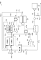
- FIG. 1 shows a carbon dioxide production system 10A according to the first embodiment of the present invention.
- the carbon dioxide production system 10A includes, as main components, a vaporizer 12, a reformer 14, a first fuel cell stack 16, a second fuel cell stack 18, a separation unit 20, a first heat exchanger 30, a second A heat exchanger 32, a combustor 40, a water tank 42, a suction pump 44, a PSA (Pressure Swing Adsorption) device 46, and a carbon dioxide recovery tank 48 are provided. Further, as shown in FIG. 2, a control unit 50 for controlling the carbon dioxide production system 10A is provided.
- a raw material gas pipe P1 is connected to the reformer 14, and the other end of the raw material gas pipe P1 is connected to a gas source (not shown). From the gas source, methane is sent to the reformer 14 by the raw material supply blower B1.
- methane is used as the raw material gas, but it is not particularly limited as long as it can be reformed, and a hydrocarbon fuel can be used.
- the hydrocarbon fuel include natural gas, LP gas (liquefied petroleum gas), coal reformed gas, lower hydrocarbon gas, and the like.
- Examples of the lower hydrocarbon gas include lower hydrocarbons having 4 or less carbon atoms such as methane, ethane, ethylene, propane, and butane, and methane used in the present embodiment is preferable.
- the hydrocarbon fuel may be a mixture of the above-described lower hydrocarbon gas, and the above-described lower hydrocarbon gas may be a gas such as natural gas, city gas, or LP gas.
- the water supply pipe P2 is connected to the vaporizer 12, and water (liquid phase) is fed by the water supply pump PO1.
- water In the vaporizer 12, water is vaporized.
- the heat of the combustor 40 described later is used.
- Steam is delivered from the vaporizer 12, and the steam pipe P3 that delivers the steam joins the raw material gas pipe P1.
- Methane and water vapor are merged in the raw material gas pipe P 1 and supplied to the reformer 14.
- the reformer 14 is adjacent to the combustor 40, the first fuel cell stack 16, and the second fuel cell stack 18, and is heated by exchanging heat with them.
- the reformer 14 reforms methane to produce fuel gas containing hydrogen and having a temperature of about 600 ° C.
- the reformer 14 is connected to the anode (fuel electrode) 16 ⁇ / b> A of the first fuel cell stack 16.
- the fuel gas generated by the reformer 14 is supplied to the anode 16A of the first fuel cell stack 16 via the fuel gas pipe P4.
- the raw material gas component that has not been reacted in the reformer 14 is also contained in the fuel gas and supplied to the anode 16A.
- the first fuel cell stack 16 is a solid oxide fuel cell stack, and has a plurality of stacked fuel cells.
- the first fuel cell stack 16 is an example of a fuel cell (first fuel cell) according to the present invention.
- the operating temperature is about 650 ° C.
- Each fuel cell has an electrolyte layer 16C, and an anode 16A and a cathode (air electrode) 16B laminated on the front and back surfaces of the electrolyte layer 16C.
- the basic configuration of the second fuel cell stack 18 is the same as that of the first fuel cell stack 16, and corresponds to the anode 18A corresponding to the anode 16A, the cathode 18B corresponding to the cathode 16B, and the electrolyte layer 16C. It has an electrolyte layer 18C.
- the oxidant gas (air) is supplied from the oxidant gas pipe P5 to the cathode 16B of the first fuel cell stack 16. Air is introduced into the oxidant gas pipe P5 by the oxidant gas blower B2.
- the oxidant gas pipe P5 is provided with a second heat exchanger 32, and air is heated by heat exchange with a non-fuel gas to be described later and supplied to the cathode 16B.
- oxygen and electrons in the oxidant gas react to generate oxygen ions.
- the generated oxygen ions reach the anode 16A of the first fuel cell stack 16 through the electrolyte layer.
- the cathode 16B is connected to a cathode offgas pipe P6 that guides the cathode offgas discharged from the cathode 16B to the cathode 18B of the second fuel cell stack 18.
- anode 16A of the first fuel cell stack 16 As shown in the following equations (2) and (3), oxygen ions that have passed through the electrolyte layer react with hydrogen and carbon monoxide in the fuel gas. Water (steam) and carbon dioxide and electrons are generated. Electrons generated at the anode 16A move from the anode 16A through the external circuit to the cathode 16B, and are thus generated in each fuel cell. Each fuel cell generates heat during power generation.
- a power meter E1 is connected to the power cable 16D that extracts power from the first fuel cell stack 16. The power output from the first fuel cell stack 16 is measured by the wattmeter E1. The amount of power generated in the first fuel cell stack 16 is controlled by the control unit 50.
- anode offgas pipe P7 One end of an anode offgas pipe P7 is connected to the anode 16A of the first fuel cell stack 16, and the anode offgas is discharged from the anode 16A to the anode offgas pipe P7.
- the anode off gas contains unreformed raw material gas components, unreacted hydrogen, unreacted carbon monoxide, carbon dioxide, water vapor, and the like.
- the fuel cell of the present invention is not limited to a solid oxide fuel cell (SOFC), but is another fuel cell in which carbon dioxide is contained in the anode off gas, for example, molten carbonate.
- SOFC solid oxide fuel cell
- a fuel cell (MCFC), a phosphoric acid fuel cell (PAFC), and a polymer electrolyte fuel cell (PEFC) may be used.
- the other end of the anode off gas pipe P7 is connected to the inflow part 24 of the separation part 20 via a first heat exchanger 30 described later.
- the separation unit 20 separates carbon dioxide and water from the anode off gas by a separation membrane 28 described later.
- the separation unit 20 includes an inflow portion 24 and a transmission portion 26.
- the inflow part 24 and the permeation part 26 are partitioned by a separation membrane 28.
- the inflow part 24 becomes the non-permeation side of the anode off gas, and the permeation part 26 becomes the permeation side.
- the separation membrane 28 has a function of transmitting carbon dioxide and water.
- the material is not particularly limited as long as it has a function of transmitting carbon dioxide and water, and examples thereof include an organic polymer film, an inorganic material film, an organic polymer-inorganic material composite film, and a liquid film.
- the anode off gas is supplied to the inflow section 24 of the separation section 20 through the anode off gas pipe P7. Carbon dioxide and water contained in the anode off gas pass through the separation membrane 28 and move to the permeation unit 26. The anode off gas remaining on the inflow portion 24 side after the concentration of carbon dioxide and water is reduced becomes regenerated fuel gas and is sent out from the inflow portion 24.
- the regenerated fuel gas pipe P9 is connected to the anode 18A of the second fuel cell stack 18, and the regenerated fuel gas is supplied to the anode 18A of the second fuel cell stack 18 via the regenerated fuel gas pipe P9. .
- Heat exchange is performed in the first heat exchanger 30 between the anode off gas flowing through the anode off gas pipe P7 and the regenerated fuel gas flowing through the regenerated fuel gas pipe P9.
- the anode off gas is cooled and the regenerated fuel gas is heated.
- the other end of the non-fuel gas pipe P16 having one end connected to the water tank 42 is connected to the permeation section 26 of the separation section 20.
- carbon dioxide and water move from the inflow portion 24 through the separation membrane 28 to the permeation portion 26.
- Carbon dioxide, water (gas phase), and other gases in the anode off-gas that have passed through the separation membrane 28 are sent out from the permeation unit 26 as non-fuel gas.
- the sent non-fuel gas is sent to the water tank 42 through the second heat exchanger 32 by the non-fuel gas pipe P16.
- water liquefied by condensation and a non-fuel gas (hereinafter referred to as “carbon dioxide rich gas”) in which water is removed and the main component is carbon dioxide are stored in a separated state.
- a recovery pipe P18 is connected to the gas storage part at the upper part of the water tank 42, and one end of a water circulation pipe P19 for supplying water to the vaporizer 12 is connected to the liquid storage part at the lower part of the water tank 42. Yes.
- the carbon dioxide rich gas is sent to the recovery pipe P18.
- a PSA device 46 is connected to the other end of the recovery pipe P18.
- components other than carbon dioxide are removed from the carbon dioxide rich gas by adsorption (hereinafter, this gas is referred to as “carbon dioxide gas”), and the gas is sent to the CO 2 pipe P20.
- One end of the CO2 pipe P20 is connected to the PSA device 46, and the other end of the CO2 pipe P20 is connected to the carbon dioxide recovery tank 48.
- the carbon dioxide gas delivered from the PSA device 46 is stored in the carbon dioxide recovery tank 48 through the CO2 pipe P20.
- a flow meter 48 ⁇ / b> A is provided at the inlet of the carbon dioxide recovery tank 48.
- the flow rate of the gas flowing into the carbon dioxide recovery tank 48 is measured by the flow meter 48A.
- the CO2 pipe P20 may be connected to a pipe for supplying to another system. Further, the filling amount and pressure of the carbon dioxide recovery tank 48 may be measured.
- the suction pump 44 is connected to the collection pipe P18.
- the suction pump 44 sucks the upstream gas and sends it to the downstream side.
- the non-fuel gas is sucked from the permeation unit 26 by the suction pump 44 and sent to the PSA device 46 at a predetermined pressure.
- the flow rate of the non-fuel gas that passes through the separation membrane 28 from the inflow portion 24 and moves to the permeation portion 26 is controlled.
- the branch pipe P21 is connected downstream of the suction pipe 44 of the recovery pipe P18.
- the branch pipe P21 is provided with an on-off valve V1.
- an on-off valve V2 is provided downstream of the portion of the recovery pipe P18 to which the branch pipe P21 is connected.
- the carbon dioxide rich gas sent to the recovery pipe P18 is sent to the PSA device 46 when the on-off valve V1 is closed and the on-off valve V2 is opened.
- the carbon dioxide rich gas is sent to the branch pipe P21 when the on-off valve V1 is opened and the on-off valve V2 is closed.
- the branch pipe P21 is open to the outside.
- the carbon dioxide recovery tank 48 cannot be filled with carbon dioxide or when it is desired to stop the carbon dioxide recovery, the carbon dioxide rich gas can be sent to the branch pipe P21 and released to the outside. Normally, the carbon dioxide rich gas is delivered to the PSA device 46.
- the second heat exchanger 32 heat exchange is performed between the non-fuel gas and air, the air is heated, and the non-fuel gas is cooled.
- the water vapor in the cooled non-fuel gas is condensed and flows into the water tank 42 and stored.
- the carbon dioxide rich gas from which the water vapor is separated and the carbon dioxide concentration is increased is sent out from the recovery pipe P18 and is recovered in the carbon dioxide recovery tank 48 via the PSA device 46.
- power is generated by the same reaction as that of the first fuel cell stack 16.
- a power meter E ⁇ b> 2 is connected to the power cable 18 ⁇ / b> D that extracts power from the second fuel cell stack 18.
- the power output from the second fuel cell stack 18 is measured by the wattmeter E2.
- the amount of power generated in the first fuel cell stack 16 is controlled by the control unit 50.
- the spent gas discharged from the anode 18A and the cathode 18B is sent to the combustor 40 through the pipe P11 and the cathode off combustion introduction pipe P12, and is used for incineration in the combustor 40.
- the carbon dioxide production system 10A of the present embodiment is a multi-stage type in which the anode off-gas that is the fuel used in the first fuel cell stack 16 is regenerated and reused as the fuel gas in the second fuel cell stack 18. It is a carbon dioxide production system.
- Combustion exhaust gas is sent from the combustor 40.
- the combustion exhaust gas flows through the combustion exhaust pipe P10 and is discharged through the vaporizer 12.
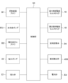
- the control unit 50 controls the entire carbon dioxide production system 10A, and includes a CPU, a ROM, a RAM, a memory, and the like.
- the memory stores data and procedures necessary for a carbon dioxide flow rate adjusting process, which will be described later, and a process during normal operation.
- the control unit 50 includes a raw material supply blower B1, a water supply pump PO1, a suction pump 44, a first fuel cell stack 16, and a second fuel cell stack 18, wattmeters E1, E2,
- the flowmeter 48A and the PSA device 46 are connected.
- the output of the raw material supply blower B1, the water supply pump PO1, the oxidant gas blower B2, the suction pump 44, and the PSA device 46 is controlled by the control unit 50.
- methane which is fuel from a gas source
- water from the water tank 42 are supplied to the vaporizer 12.
- the supplied methane and water are mixed, and heat is obtained from the combustion exhaust gas flowing through the combustion exhaust pipe P ⁇ b> 10, and the water is vaporized to become steam.
- Methane and water vapor are sent from the vaporizer 12 to the reformer 14 via the pipe P1.
- a fuel gas containing about 600 ° C. containing hydrogen is generated by the steam reforming reaction.
- the fuel gas is supplied to the anode 16A of the first fuel cell stack 16 through the fuel gas pipe P4.
- the air is supplied to the cathode 16B of the first fuel cell stack 16 through the oxidant gas pipe P5.
- the anode off gas is discharged from the anode 16A of the fuel cell stack 16.
- the cathode off gas is discharged from the cathode 16B.
- the cathode off gas is supplied to the cathode 18B of the second fuel cell stack 18 through the cathode off gas pipe P6.
- the anode off gas discharged from the anode 16A is guided to the anode off gas pipe P7, and flows into the inflow section 24 of the separation section 20 through the first heat exchanger 30.
- the temperature of the anode off gas decreases from about 650 ° C. to a certain degree, for example, about 200 ° C.
- the temperature here is a temperature at which the gas phase state of water in the anode off-gas is maintained.
- Carbon dioxide and water (gas phase) in the anode off-gas are separated by passing through the separation membrane 28 and moving to the permeation section 26 side.
- Regenerated fuel gas is sent out from the inflow portion 24, is heated to about 600 ° C. through the first heat exchanger 30, and is supplied to the anode 18A of the second fuel cell stack 18 through the regenerated fuel gas pipe P9.
- the spent gas at the anode 18A and the cathode 18B is sent to the combustor 40 through the pipes P11 and P12, and is used for incineration by the combustor 40.
- the combustion exhaust gas from the combustor 40 is exhausted through heat exchange in the vaporizer 12.
- the suction pump 44 sucks non-fuel gas from the permeation section 26 with a predetermined output.
- the output of the suction pump 44 here is set according to the amount of power generation required in the carbon dioxide production system 10A.
- the non-fuel gas passes through the separation membrane 28 and flows into the permeation unit 26 and is sent out from the permeation unit 26.
- the sent non-fuel gas is cooled by the second heat exchanger 32 by heat exchange with the air passing through the oxidant gas pipe P5.
- the water vapor in the non-fuel gas is condensed and separated from the non-fuel gas.
- Non-fuel gas and condensed water are sent to the water tank 42.
- the carbon dioxide rich gas from which water has been separated from the non-fuel gas is sent from the water tank 42 to the recovery pipe P18, sent to the PSA device 46, and recovered to the carbon dioxide recovery tank 48 via the PSA device 46.
- water is condensed by heat exchange in the second heat exchanger 32 after the carbon dioxide and water (gas phase) are separated by the separation membrane 28, so that the separation by the separation membrane is performed.
- it can be made to send out from the inflow part 24, maintaining the temperature of regeneration fuel gas high. Therefore, the regenerated fuel gas for power generation in the second fuel cell stack 18 can be efficiently reused.
- the water vapor in the discharged non-fuel gas can be easily separated from the permeation unit 26 by condensation, and the non-fuel gas having a high carbon dioxide concentration can be recovered.
- step S10 the measurement (flow rate measurement value) of the flow meter 48A is acquired, and in step S12, it is compared with the set value.
- step S14 the output of the suction pump 44 is adjusted based on the comparison result between the flow rate measurement value and the set value. In the adjustment, when the flow rate measurement value is smaller than the set value, the output of the suction pump 44 is increased to increase the amount of non-fuel gas that permeates the separation membrane 28, and the flow rate measurement value is larger than the set value. For this, the output of the suction pump 44 is lowered to reduce the amount of non-fuel gas that permeates the separation membrane 28.
- the flow rate of the carbon dioxide gas recovered by the carbon dioxide recovery tank 48 can be set to a desired setting range.
- the end of the process is input from the input unit.
- step S16 it is determined whether or not an end input has been received. If the determination is affirmative, the carbon dioxide flow rate adjusting process is ended.
- the output of the suction pump 44 by adjusting the output of the suction pump 44, the flow rate of the carbon dioxide gas recovered in the carbon dioxide recovery tank 48 is brought close to the set value, but the output of the raw material supply blower B1 and the water supply pump PO1. May be adjusted.
- all of the suction pump 44, the raw material supply blower B1, and the water supply pump PO1 may be adjusted, or may be adjusted by a combination of any of a plurality of devices.
- the pressure in the carbon dioxide recovery tank 48 may be measured, or the filling amount may be measured.
- the output of the raw material supply blower B1 when the flow rate measurement value is smaller than the set value, the output of the raw material supply blower B1 is increased to increase the flow rate of the anode off gas flowing into the separation unit 20, This increases the amount of non-fuel gas that permeates the separation membrane 28. Further, when the flow rate measurement value is larger than the set value, the output of the raw material supply blower B1 is lowered to reduce the flow rate of the anode off gas flowing into the separation unit 20, and thereby the non-fuel that permeates the separation membrane 28. Reduce the amount of gas. When adjusting the output of the raw material supply blower B1, the amount of power generation is also adjusted as appropriate.
- the output of the water supply pump PO1 when adjusting the output of the water supply pump PO1, if the measured flow rate is smaller than the set value, the output of the water supply pump PO1 is increased and the flow rate of the anode off gas flowing into the separation unit 20 is increased. Thus, the amount of non-fuel gas that permeates the separation membrane 28 is increased. Further, when the flow rate measurement value is larger than the set value, the output of the water supply pump PO1 is lowered to reduce the flow rate of the anode off gas flowing into the separation unit 20, and thereby the non-fuel that permeates the separation membrane 28. Reduce the amount of gas.
- the power generation amount in the carbon dioxide production system 10A may be adjusted so that the flow rate of the carbon dioxide gas recovered in the carbon dioxide recovery tank 48 approaches the set value.
- the amount of power generation is the total power generated by the carbon dioxide production system 10A (the sum of the power generated by the first fuel cell stack 16 and the power generated by the second fuel cell stack 18, that is, the wattmeter E1 Or the measured value E2 of the wattmeter E2), or based on the power generated by the first fuel cell stack 16 (measured value of the wattmeter E1). You may adjust.
- the power generation amount in the first fuel cell stack 16 and the second fuel cell stack 18 When adjusting with the whole electric power generated with the carbon dioxide production system 10A, when the flow rate measurement value is smaller than the set value, the power generation amount in the first fuel cell stack 16 and the second fuel cell stack 18 The sum of the power generation amount at (the sum of the measured value at the wattmeter E1 and the measured value E2 at the wattmeter E2) is increased. On the other hand, when the flow rate measurement value is larger than the set value, the sum of the power generation amount in the first fuel cell stack 16 and the power generation amount in the second fuel cell stack 18 (measurement value and power in the wattmeter E1). The sum of the measured values E2 in the total E2) is decreased.
- the electric power generated by the first fuel cell stack 16 is adjusted so as to obtain a desired flow rate of carbon dioxide, It is possible to adjust the electric power generated by the second fuel cell stack 18 so that the entire electric power generated by the carbon dioxide production system 10A becomes a desired value.
- the power generation amount (with the wattmeter E1) Increase the measured value).
- the power generation amount in the first fuel cell stack 16 (measurement value in the wattmeter E1) is decreased.
- the electric power generated with the 2nd fuel cell stack 18 may be adjusted, and in the 2nd fuel cell stack 18 It is good even if it does not adjust.
- the PSA device 46 is provided, but the PSA device 46 is not necessarily installed.
- the concentration of carbon dioxide recovered in the carbon dioxide recovery tank 48 can be adjusted by installing the PSA device 46 and adjusting the adsorption conditions for carbon dioxide and other components.
- carbon dioxide is recovered between the first fuel cell stack 16 and the second fuel cell stack 18 in one carbon dioxide production system.
- Carbon may be recovered. That is, an anode of a fuel cell stack is connected in series between a plurality of fuel cell systems, and is discharged from an anode of a fuel cell stack of an upstream fuel cell system and supplied to an anode of a downstream fuel cell system Carbon dioxide may be separated and recovered from the previous anode off gas.
- the carbon dioxide production system 10 ⁇ / b> B of this embodiment does not have the PSA device 46.
- the combustion exhaust gas discharged from the vaporizer 12 through the combustion exhaust gas pipe P10 is branched into a combustion exhaust gas exhaust pipe P10A and a temperature adjustment pipe P10B.
- the combustion exhaust gas is exhausted from the combustion exhaust gas exhaust pipe P10A.
- the temperature adjustment pipe P10B is connected to the upstream side of the oxidant gas blower B2.
- the temperature adjustment pipe P10B is provided with a flow rate adjustment valve 54, and the flow rate of the combustion exhaust gas sent to the oxidant gas blower B2 is adjusted by the opening degree.
- the flow rate adjusting valve 54 is connected to the control unit 50, and the opening degree is adjusted by the control unit 50.
- a composition detector 48B is provided at the inlet of the carbon dioxide recovery tank 48 in place of the flow meter 48A.
- the composition detector 48B can detect the carbon dioxide concentration of the gas flowing into the carbon dioxide recovery tank 48.
- the composition detector 48 ⁇ / b> B is connected to the control unit 50 and transmits the detected carbon dioxide concentration value to the control unit 50.
- the concentration of carbon dioxide recovered by the carbon dioxide recovery tank 48 can be adjusted.
- a desired carbon dioxide concentration value is input from an input unit (not shown).
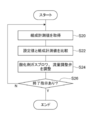
- the input value (set value) is sent to the control unit 50, and the control unit 50 executes the carbon dioxide flow rate adjustment process shown in FIG.
- step S20 the measurement value (composition measurement value) of the composition detector 48B is acquired, and in step S22, it is compared with the set value.
- step S24 the flow rate adjustment valve 54 or the oxidant gas blower B2 is adjusted based on the comparison result between the measured composition value and the set value.
- the flow rate adjustment valve 54 is closed to increase the output of the oxidant gas blower B2.
- the flow rate of the oxidant gas passing through the oxidant gas pipe P5 increases, the water vapor condensed by the heat exchange in the second heat exchanger 32 increases, and the carbon dioxide recovered in the carbon dioxide recovery tank 48
- the gas concentration increases.
- the flow rate adjustment valve 54 is opened.
- the temperature of the oxidant gas passing through the oxidant gas pipe P ⁇ b> 5 rises, the water vapor condensed by heat exchange in the second heat exchanger 32 decreases, and the carbon dioxide recovered in the carbon dioxide recovery tank 48.
- the gas concentration is lowered.
- the concentration of the carbon dioxide gas recovered in the carbon dioxide recovery tank 48 can be set to a desired setting range by feedback control of the oxidant gas blower B2 and the flow rate adjusting valve 54 based on the composition measurement value. it can.
- the end of the process is input from the input unit.
- step S26 it is determined whether or not an end input has been received. If the determination is affirmative, the carbon dioxide concentration adjustment process is ended.
- FIG. 7 shows a carbon dioxide production system 10C according to the third embodiment of the present invention.
- the carbon dioxide production system 10C is different from the carbon dioxide production system 10A described in the first embodiment in that the second fuel cell stack 18 is not provided.
- the regenerated fuel gas pipe P9 connected to the separation unit 20 is branched at a branching portion D1 provided on the upstream side of the first heat exchanger 30.
- One of the branched circulation gas pipes P9-1 is connected to the pipe P1 via the first heat exchanger 30.
- the other branched regenerative fuel gas pipe P9-2 is connected to the combustor 40.
- the branch portion D1 the regenerated fuel gas is divided into the circulation gas pipe P9-1 and the regenerated fuel gas pipe P9-2.
- the regenerated fuel gas introduced into the reformer 14 via the circulating gas pipe P9-1 is mixed with methane and water vapor supplied from the vaporizer 12, and supplied to the reformer 14.
- the regenerated fuel gas introduced into the combustor 40 through the regenerated fuel gas pipe P9-2 is burned in the combustor 40.
- the cathode offgas discharged from the cathode 16B is introduced into the combustor 40 via the cathode offgas pipe P6.
- the anode off-gas that is the spent fuel in the first fuel cell stack 16 is regenerated and reused in the first fuel cell stack 16 again. It is a carbon production system. In this embodiment, the same effect as that of the first embodiment can be obtained.
- FIG. 8 shows a carbon dioxide production system 10D according to the fourth embodiment of the present invention. Similarly to the carbon dioxide production system 10C described in the third embodiment, the carbon dioxide production system 10D regenerates the anode off-gas that is the spent fuel in the first fuel cell stack 16, and again the first fuel cell. This is a circulating carbon dioxide production system that is reused in the cell stack 16.
- the carbon dioxide production system 10D does not have the PSA device 46 as in the second embodiment, as compared with the carbon dioxide production system 10C described in the third embodiment.
- the combustion exhaust gas discharged from the vaporizer 12 through the combustion exhaust gas pipe P10 is branched into a combustion exhaust gas exhaust pipe P10A and a temperature adjustment pipe P10B.
- the combustion exhaust gas is exhausted from the combustion exhaust gas exhaust pipe P10A.
- the temperature adjustment pipe P10B is connected to the upstream side of the oxidant gas blower B2.
- the temperature adjustment pipe P10B is provided with a flow rate adjustment valve 54, and the flow rate of the combustion exhaust gas sent to the oxidant gas blower B2 is adjusted by the opening degree.
- the present invention is not limited to the first to fourth embodiments described above, and is implemented by a person skilled in the art in combination with the above-described embodiments within the technical idea of the present invention.
- the installation position and combination of the heat exchanger, the blower, and the pump are not limited to these embodiments.
- the carbon dioxide recovery tank 48 may contain a carbon dioxide absorbent or adsorbent. Further, it may be a carbon dioxide liquefying device or a carbon dioxide solidifying device.
- a hydrocarbon raw material such as methane is reformed by the reformer 14 to obtain a fuel gas.
- a fuel gas containing a carbon compound may be generated outside and supplied to the fuel cell system. Good.
- Carbon compounds include carbon monoxide in addition to hydrocarbons such as methane.
- a hydrocarbon raw material such as methane may be directly supplied to the first fuel cell stack 16 as a fuel gas to generate electric power.
Landscapes
- Chemical & Material Sciences (AREA)
- Engineering & Computer Science (AREA)
- Chemical Kinetics & Catalysis (AREA)
- General Chemical & Material Sciences (AREA)
- Sustainable Energy (AREA)
- Life Sciences & Earth Sciences (AREA)
- Sustainable Development (AREA)
- Electrochemistry (AREA)
- Manufacturing & Machinery (AREA)
- Oil, Petroleum & Natural Gas (AREA)
- Analytical Chemistry (AREA)
- Combustion & Propulsion (AREA)
- Organic Chemistry (AREA)
- Fuel Cell (AREA)
- Inorganic Chemistry (AREA)
- Separation Using Semi-Permeable Membranes (AREA)
- Separation Of Gases By Adsorption (AREA)
- Carbon And Carbon Compounds (AREA)
Priority Applications (5)
| Application Number | Priority Date | Filing Date | Title |
|---|---|---|---|
| CN201980010548.5A CN111837277B (zh) | 2018-02-06 | 2019-01-24 | 二氧化碳制造系统 |
| US16/967,036 US11581559B2 (en) | 2018-02-06 | 2019-01-24 | Carbon dioxide production system |
| EP19751630.5A EP3751655A4 (en) | 2018-02-06 | 2019-01-24 | CARBON DIOXIDE GENERATION SYSTEM |
| KR1020207024705A KR102797194B1 (ko) | 2018-02-06 | 2019-01-24 | 이산화탄소 제조 시스템 |
| EP22195831.7A EP4142001A3 (en) | 2018-02-06 | 2019-01-24 | Carbon dioxide production system |
Applications Claiming Priority (2)
| Application Number | Priority Date | Filing Date | Title |
|---|---|---|---|
| JP2018-019502 | 2018-02-06 | ||
| JP2018019502A JP6664423B2 (ja) | 2018-02-06 | 2018-02-06 | 二酸化炭素製造システム |
Publications (1)
| Publication Number | Publication Date |
|---|---|
| WO2019155901A1 true WO2019155901A1 (ja) | 2019-08-15 |
Family
ID=67549037
Family Applications (1)
| Application Number | Title | Priority Date | Filing Date |
|---|---|---|---|
| PCT/JP2019/002372 Ceased WO2019155901A1 (ja) | 2018-02-06 | 2019-01-24 | 二酸化炭素製造システム |
Country Status (6)
| Country | Link |
|---|---|
| US (1) | US11581559B2 (https=) |
| EP (2) | EP4142001A3 (https=) |
| JP (1) | JP6664423B2 (https=) |
| KR (1) | KR102797194B1 (https=) |
| CN (1) | CN111837277B (https=) |
| WO (1) | WO2019155901A1 (https=) |
Cited By (1)
| Publication number | Priority date | Publication date | Assignee | Title |
|---|---|---|---|---|
| JP2023033659A (ja) * | 2021-08-27 | 2023-03-13 | 国立大学法人九州大学 | 二酸化炭素の回収装置、燃焼システム、発電システム、及び二酸化炭素の回収方法 |
Families Citing this family (11)
| Publication number | Priority date | Publication date | Assignee | Title |
|---|---|---|---|---|
| JP7245136B2 (ja) * | 2019-09-13 | 2023-03-23 | 東京瓦斯株式会社 | 燃料電池システム |
| JP7370792B2 (ja) * | 2019-09-30 | 2023-10-30 | 東京瓦斯株式会社 | 燃料電池システム、及び燃料電池システムの運転方法 |
| DE102020124072A1 (de) * | 2020-09-16 | 2022-03-17 | Audi Aktiengesellschaft | Verfahren zum Betreiben einer Festoxid-Brennstoffzellenvorrichtung, Festoxid-Brennstoffzellenvorrichtung und Kraftfahrzeug mit einer solchen |
| DE102020214166A1 (de) * | 2020-11-11 | 2022-05-12 | Ford Global Technologies, Llc | Verfahren zum Betrieb eines Brennstoffzellen-Kraftfahrzeugs |
| JP7407351B2 (ja) * | 2021-01-07 | 2024-01-04 | パナソニックIpマネジメント株式会社 | 二酸化炭素分離回収装置 |
| KR102691665B1 (ko) * | 2022-12-20 | 2024-08-05 | (주)에프씨아이 | Sofc-psa 하이브리드 시스템 |
| JP2024147869A (ja) * | 2023-04-04 | 2024-10-17 | 三菱電機株式会社 | 燃料電池システム |
| JP7805344B2 (ja) * | 2023-12-12 | 2026-01-23 | 三菱電機株式会社 | 燃料電池システム |
| WO2025243493A1 (ja) * | 2024-05-24 | 2025-11-27 | 三菱電機株式会社 | 燃料電池システム |
| JP7661637B1 (ja) * | 2024-05-24 | 2025-04-14 | 三菱電機株式会社 | 燃料電池システム |
| WO2025243492A1 (ja) * | 2024-05-24 | 2025-11-27 | 三菱電機株式会社 | ガス分離システム |
Citations (3)
| Publication number | Priority date | Publication date | Assignee | Title |
|---|---|---|---|---|
| JP2012071290A (ja) * | 2010-09-30 | 2012-04-12 | Hitachi Ltd | 二酸化炭素回収方法及び二酸化炭素回収装置 |
| JP2016184504A (ja) * | 2015-03-26 | 2016-10-20 | 東京瓦斯株式会社 | 燃料電池システム |
| JP2018019502A (ja) | 2016-07-27 | 2018-02-01 | 京セラ株式会社 | 送受電アンテナシステム |
Family Cites Families (12)
| Publication number | Priority date | Publication date | Assignee | Title |
|---|---|---|---|---|
| JP3000118B2 (ja) | 1992-08-04 | 2000-01-17 | 運輸省船舶技術研究所長 | 固体酸化物燃料電池を用い電力発生と同時に二酸化炭素を分離回収する方法 |
| EP1804322B1 (en) * | 2004-10-19 | 2011-12-14 | Central Research Institute of Electric Power Industry | Combined power generation equipment |
| JP4916138B2 (ja) * | 2005-07-08 | 2012-04-11 | 中国電力株式会社 | 発電システム |
| JP2009224264A (ja) | 2008-03-18 | 2009-10-01 | Toyota Motor Corp | 燃料電池システム |
| JP2010170888A (ja) * | 2009-01-23 | 2010-08-05 | Sony Corp | 燃料電池システムおよび電子機器 |
| CA2764207A1 (en) * | 2009-06-16 | 2010-12-23 | Shell Internationale Research Maatschappij B.V. | Systems and processes for operating fuel cell systems |
| CN105960729B (zh) | 2014-01-17 | 2019-02-22 | Ez-能源有限公司 | 通过气态烃进料生产二氧化碳和电力的方法和系统 |
| WO2015124183A1 (en) * | 2014-02-19 | 2015-08-27 | Htceramix S.A. | Method and system for producing carbon dioxide, purified hydrogen and electricity from a reformed process gas feed |
| US10186724B2 (en) * | 2015-02-04 | 2019-01-22 | Bloom Energy Corporation | Carbon dioxide separator, fuel cell system including same, and method of operating the fuel cell system |
| JP6152436B1 (ja) * | 2016-01-26 | 2017-06-21 | 東京瓦斯株式会社 | 燃料電池システム |
| JP6084314B1 (ja) * | 2016-01-26 | 2017-02-22 | 東京瓦斯株式会社 | 燃料電池システム |
| JP6986839B2 (ja) | 2016-12-28 | 2021-12-22 | 東京瓦斯株式会社 | 燃料電池システム、及び二酸化炭素分離方法 |
-
2018
- 2018-02-06 JP JP2018019502A patent/JP6664423B2/ja active Active
-
2019
- 2019-01-24 WO PCT/JP2019/002372 patent/WO2019155901A1/ja not_active Ceased
- 2019-01-24 EP EP22195831.7A patent/EP4142001A3/en active Pending
- 2019-01-24 KR KR1020207024705A patent/KR102797194B1/ko active Active
- 2019-01-24 EP EP19751630.5A patent/EP3751655A4/en not_active Withdrawn
- 2019-01-24 US US16/967,036 patent/US11581559B2/en active Active
- 2019-01-24 CN CN201980010548.5A patent/CN111837277B/zh active Active
Patent Citations (3)
| Publication number | Priority date | Publication date | Assignee | Title |
|---|---|---|---|---|
| JP2012071290A (ja) * | 2010-09-30 | 2012-04-12 | Hitachi Ltd | 二酸化炭素回収方法及び二酸化炭素回収装置 |
| JP2016184504A (ja) * | 2015-03-26 | 2016-10-20 | 東京瓦斯株式会社 | 燃料電池システム |
| JP2018019502A (ja) | 2016-07-27 | 2018-02-01 | 京セラ株式会社 | 送受電アンテナシステム |
Cited By (2)
| Publication number | Priority date | Publication date | Assignee | Title |
|---|---|---|---|---|
| JP2023033659A (ja) * | 2021-08-27 | 2023-03-13 | 国立大学法人九州大学 | 二酸化炭素の回収装置、燃焼システム、発電システム、及び二酸化炭素の回収方法 |
| JP7738314B2 (ja) | 2021-08-27 | 2025-09-16 | 株式会社Jccl | 二酸化炭素の回収装置、燃焼システム、発電システム、及び二酸化炭素の回収方法 |
Also Published As
| Publication number | Publication date |
|---|---|
| KR20200116957A (ko) | 2020-10-13 |
| JP2019139858A (ja) | 2019-08-22 |
| US20210036351A1 (en) | 2021-02-04 |
| US11581559B2 (en) | 2023-02-14 |
| EP3751655A4 (en) | 2022-07-13 |
| EP3751655A1 (en) | 2020-12-16 |
| JP6664423B2 (ja) | 2020-03-13 |
| KR102797194B1 (ko) | 2025-04-18 |
| CN111837277A (zh) | 2020-10-27 |
| EP4142001A3 (en) | 2025-06-04 |
| EP4142001A2 (en) | 2023-03-01 |
| CN111837277B (zh) | 2023-09-12 |
Similar Documents
| Publication | Publication Date | Title |
|---|---|---|
| JP6664423B2 (ja) | 二酸化炭素製造システム | |
| CN100429816C (zh) | 具有两种不同类型燃料电池的燃料电池发电系统和其控制方法 | |
| KR102383498B1 (ko) | 연료 전지 시스템 | |
| JP6808677B2 (ja) | 二酸化炭素供給システム | |
| JP6470778B2 (ja) | 燃料電池システム及び発電方法 | |
| JP6084314B1 (ja) | 燃料電池システム | |
| JP6017660B1 (ja) | 燃料電池システム | |
| JP2018107098A (ja) | 燃料電池システム、及び二酸化炭素分離方法 | |
| JP6163525B2 (ja) | 燃料電池システム | |
| JP7148320B2 (ja) | 二酸化炭素回収型燃料電池発電システム | |
| JP2019169419A (ja) | 燃料電池システム | |
| JP6688818B2 (ja) | 燃料電池システム | |
| JP2017084768A (ja) | 燃料電池システム | |
| JP6134832B1 (ja) | 燃料電池システム | |
| JP2017084541A (ja) | 燃料電池システム | |
| JP6765465B2 (ja) | 燃料電池システム | |
| JP6704011B2 (ja) | 燃料電池システム | |
| JP7102204B2 (ja) | 燃料電池システム | |
| JP6847900B2 (ja) | 二酸化炭素回収型燃料電池発電システム | |
| JP7117191B2 (ja) | 二酸化炭素回収型燃料電池発電システム | |
| JP6997032B2 (ja) | 燃料電池システム | |
| JP7065918B2 (ja) | 二酸化炭素供給システム | |
| JP6947678B2 (ja) | 燃料電池システム | |
| JP7245136B2 (ja) | 燃料電池システム | |
| JP7335788B2 (ja) | 燃料電池システム |
Legal Events
| Date | Code | Title | Description |
|---|---|---|---|
| 121 | Ep: the epo has been informed by wipo that ep was designated in this application |
Ref document number: 19751630 Country of ref document: EP Kind code of ref document: A1 |
|
| NENP | Non-entry into the national phase |
Ref country code: DE |
|
| ENP | Entry into the national phase |
Ref document number: 20207024705 Country of ref document: KR Kind code of ref document: A |
|
| ENP | Entry into the national phase |
Ref document number: 2019751630 Country of ref document: EP Effective date: 20200907 |