WO2019155901A1 - 二酸化炭素製造システム - Google Patents
二酸化炭素製造システム Download PDFInfo
- Publication number
- WO2019155901A1 WO2019155901A1 PCT/JP2019/002372 JP2019002372W WO2019155901A1 WO 2019155901 A1 WO2019155901 A1 WO 2019155901A1 JP 2019002372 W JP2019002372 W JP 2019002372W WO 2019155901 A1 WO2019155901 A1 WO 2019155901A1
- Authority
- WO
- WIPO (PCT)
- Prior art keywords
- carbon dioxide
- gas
- fuel gas
- production system
- fuel
- Prior art date
Links
Images


Classifications
-
- C—CHEMISTRY; METALLURGY
- C01—INORGANIC CHEMISTRY
- C01B—NON-METALLIC ELEMENTS; COMPOUNDS THEREOF; METALLOIDS OR COMPOUNDS THEREOF NOT COVERED BY SUBCLASS C01C
- C01B32/00—Carbon; Compounds thereof
- C01B32/50—Carbon dioxide
-
- B—PERFORMING OPERATIONS; TRANSPORTING
- B01—PHYSICAL OR CHEMICAL PROCESSES OR APPARATUS IN GENERAL
- B01D—SEPARATION
- B01D53/00—Separation of gases or vapours; Recovering vapours of volatile solvents from gases; Chemical or biological purification of waste gases, e.g. engine exhaust gases, smoke, fumes, flue gases, aerosols
- B01D53/22—Separation of gases or vapours; Recovering vapours of volatile solvents from gases; Chemical or biological purification of waste gases, e.g. engine exhaust gases, smoke, fumes, flue gases, aerosols by diffusion
-
- H—ELECTRICITY
- H01—ELECTRIC ELEMENTS
- H01M—PROCESSES OR MEANS, e.g. BATTERIES, FOR THE DIRECT CONVERSION OF CHEMICAL ENERGY INTO ELECTRICAL ENERGY
- H01M8/00—Fuel cells; Manufacture thereof
- H01M8/04—Auxiliary arrangements, e.g. for control of pressure or for circulation of fluids
- H01M8/04007—Auxiliary arrangements, e.g. for control of pressure or for circulation of fluids related to heat exchange
- H01M8/04014—Heat exchange using gaseous fluids; Heat exchange by combustion of reactants
- H01M8/04022—Heating by combustion
-
- H—ELECTRICITY
- H01—ELECTRIC ELEMENTS
- H01M—PROCESSES OR MEANS, e.g. BATTERIES, FOR THE DIRECT CONVERSION OF CHEMICAL ENERGY INTO ELECTRICAL ENERGY
- H01M8/00—Fuel cells; Manufacture thereof
- H01M8/04—Auxiliary arrangements, e.g. for control of pressure or for circulation of fluids
- H01M8/04082—Arrangements for control of reactant parameters, e.g. pressure or concentration
- H01M8/04089—Arrangements for control of reactant parameters, e.g. pressure or concentration of gaseous reactants
- H01M8/04119—Arrangements for control of reactant parameters, e.g. pressure or concentration of gaseous reactants with simultaneous supply or evacuation of electrolyte; Humidifying or dehumidifying
- H01M8/04156—Arrangements for control of reactant parameters, e.g. pressure or concentration of gaseous reactants with simultaneous supply or evacuation of electrolyte; Humidifying or dehumidifying with product water removal
-
- H—ELECTRICITY
- H01—ELECTRIC ELEMENTS
- H01M—PROCESSES OR MEANS, e.g. BATTERIES, FOR THE DIRECT CONVERSION OF CHEMICAL ENERGY INTO ELECTRICAL ENERGY
- H01M8/00—Fuel cells; Manufacture thereof
- H01M8/04—Auxiliary arrangements, e.g. for control of pressure or for circulation of fluids
- H01M8/04291—Arrangements for managing water in solid electrolyte fuel cell systems
-
- H—ELECTRICITY
- H01—ELECTRIC ELEMENTS
- H01M—PROCESSES OR MEANS, e.g. BATTERIES, FOR THE DIRECT CONVERSION OF CHEMICAL ENERGY INTO ELECTRICAL ENERGY
- H01M8/00—Fuel cells; Manufacture thereof
- H01M8/04—Auxiliary arrangements, e.g. for control of pressure or for circulation of fluids
- H01M8/04298—Processes for controlling fuel cells or fuel cell systems
- H01M8/04313—Processes for controlling fuel cells or fuel cell systems characterised by the detection or assessment of variables; characterised by the detection or assessment of failure or abnormal function
- H01M8/0438—Pressure; Ambient pressure; Flow
- H01M8/04425—Pressure; Ambient pressure; Flow at auxiliary devices, e.g. reformers, compressors, burners
-
- H—ELECTRICITY
- H01—ELECTRIC ELEMENTS
- H01M—PROCESSES OR MEANS, e.g. BATTERIES, FOR THE DIRECT CONVERSION OF CHEMICAL ENERGY INTO ELECTRICAL ENERGY
- H01M8/00—Fuel cells; Manufacture thereof
- H01M8/04—Auxiliary arrangements, e.g. for control of pressure or for circulation of fluids
- H01M8/04298—Processes for controlling fuel cells or fuel cell systems
- H01M8/04694—Processes for controlling fuel cells or fuel cell systems characterised by variables to be controlled
- H01M8/04746—Pressure; Flow
- H01M8/04753—Pressure; Flow of fuel cell reactants
-
- H—ELECTRICITY
- H01—ELECTRIC ELEMENTS
- H01M—PROCESSES OR MEANS, e.g. BATTERIES, FOR THE DIRECT CONVERSION OF CHEMICAL ENERGY INTO ELECTRICAL ENERGY
- H01M8/00—Fuel cells; Manufacture thereof
- H01M8/04—Auxiliary arrangements, e.g. for control of pressure or for circulation of fluids
- H01M8/04298—Processes for controlling fuel cells or fuel cell systems
- H01M8/04694—Processes for controlling fuel cells or fuel cell systems characterised by variables to be controlled
- H01M8/04746—Pressure; Flow
- H01M8/04776—Pressure; Flow at auxiliary devices, e.g. reformer, compressor, burner
-
- H—ELECTRICITY
- H01—ELECTRIC ELEMENTS
- H01M—PROCESSES OR MEANS, e.g. BATTERIES, FOR THE DIRECT CONVERSION OF CHEMICAL ENERGY INTO ELECTRICAL ENERGY
- H01M8/00—Fuel cells; Manufacture thereof
- H01M8/04—Auxiliary arrangements, e.g. for control of pressure or for circulation of fluids
- H01M8/04298—Processes for controlling fuel cells or fuel cell systems
- H01M8/04694—Processes for controlling fuel cells or fuel cell systems characterised by variables to be controlled
- H01M8/04791—Concentration; Density
-
- H—ELECTRICITY
- H01—ELECTRIC ELEMENTS
- H01M—PROCESSES OR MEANS, e.g. BATTERIES, FOR THE DIRECT CONVERSION OF CHEMICAL ENERGY INTO ELECTRICAL ENERGY
- H01M8/00—Fuel cells; Manufacture thereof
- H01M8/04—Auxiliary arrangements, e.g. for control of pressure or for circulation of fluids
- H01M8/04298—Processes for controlling fuel cells or fuel cell systems
- H01M8/04694—Processes for controlling fuel cells or fuel cell systems characterised by variables to be controlled
- H01M8/04858—Electric variables
- H01M8/04925—Power, energy, capacity or load
- H01M8/0494—Power, energy, capacity or load of fuel cell stacks
-
- H—ELECTRICITY
- H01—ELECTRIC ELEMENTS
- H01M—PROCESSES OR MEANS, e.g. BATTERIES, FOR THE DIRECT CONVERSION OF CHEMICAL ENERGY INTO ELECTRICAL ENERGY
- H01M8/00—Fuel cells; Manufacture thereof
- H01M8/06—Combination of fuel cells with means for production of reactants or for treatment of residues
- H01M8/0606—Combination of fuel cells with means for production of reactants or for treatment of residues with means for production of gaseous reactants
- H01M8/0612—Combination of fuel cells with means for production of reactants or for treatment of residues with means for production of gaseous reactants from carbon-containing material
- H01M8/0618—Reforming processes, e.g. autothermal, partial oxidation or steam reforming
-
- H—ELECTRICITY
- H01—ELECTRIC ELEMENTS
- H01M—PROCESSES OR MEANS, e.g. BATTERIES, FOR THE DIRECT CONVERSION OF CHEMICAL ENERGY INTO ELECTRICAL ENERGY
- H01M8/00—Fuel cells; Manufacture thereof
- H01M8/06—Combination of fuel cells with means for production of reactants or for treatment of residues
- H01M8/0662—Treatment of gaseous reactants or gaseous residues, e.g. cleaning
- H01M8/0668—Removal of carbon monoxide or carbon dioxide
-
- H—ELECTRICITY
- H01—ELECTRIC ELEMENTS
- H01M—PROCESSES OR MEANS, e.g. BATTERIES, FOR THE DIRECT CONVERSION OF CHEMICAL ENERGY INTO ELECTRICAL ENERGY
- H01M8/00—Fuel cells; Manufacture thereof
- H01M8/06—Combination of fuel cells with means for production of reactants or for treatment of residues
- H01M8/0662—Treatment of gaseous reactants or gaseous residues, e.g. cleaning
- H01M8/0687—Reactant purification by the use of membranes or filters
-
- H—ELECTRICITY
- H01—ELECTRIC ELEMENTS
- H01M—PROCESSES OR MEANS, e.g. BATTERIES, FOR THE DIRECT CONVERSION OF CHEMICAL ENERGY INTO ELECTRICAL ENERGY
- H01M8/00—Fuel cells; Manufacture thereof
- H01M8/24—Grouping of fuel cells, e.g. stacking of fuel cells
- H01M8/249—Grouping of fuel cells, e.g. stacking of fuel cells comprising two or more groupings of fuel cells, e.g. modular assemblies
-
- B—PERFORMING OPERATIONS; TRANSPORTING
- B01—PHYSICAL OR CHEMICAL PROCESSES OR APPARATUS IN GENERAL
- B01D—SEPARATION
- B01D2256/00—Main component in the product gas stream after treatment
- B01D2256/22—Carbon dioxide
-
- B—PERFORMING OPERATIONS; TRANSPORTING
- B01—PHYSICAL OR CHEMICAL PROCESSES OR APPARATUS IN GENERAL
- B01D—SEPARATION
- B01D53/00—Separation of gases or vapours; Recovering vapours of volatile solvents from gases; Chemical or biological purification of waste gases, e.g. engine exhaust gases, smoke, fumes, flue gases, aerosols
- B01D53/02—Separation of gases or vapours; Recovering vapours of volatile solvents from gases; Chemical or biological purification of waste gases, e.g. engine exhaust gases, smoke, fumes, flue gases, aerosols by adsorption, e.g. preparative gas chromatography
- B01D53/04—Separation of gases or vapours; Recovering vapours of volatile solvents from gases; Chemical or biological purification of waste gases, e.g. engine exhaust gases, smoke, fumes, flue gases, aerosols by adsorption, e.g. preparative gas chromatography with stationary adsorbents
- B01D53/047—Pressure swing adsorption
-
- B—PERFORMING OPERATIONS; TRANSPORTING
- B01—PHYSICAL OR CHEMICAL PROCESSES OR APPARATUS IN GENERAL
- B01D—SEPARATION
- B01D53/00—Separation of gases or vapours; Recovering vapours of volatile solvents from gases; Chemical or biological purification of waste gases, e.g. engine exhaust gases, smoke, fumes, flue gases, aerosols
- B01D53/26—Drying gases or vapours
- B01D53/268—Drying gases or vapours by diffusion
-
- H—ELECTRICITY
- H01—ELECTRIC ELEMENTS
- H01M—PROCESSES OR MEANS, e.g. BATTERIES, FOR THE DIRECT CONVERSION OF CHEMICAL ENERGY INTO ELECTRICAL ENERGY
- H01M8/00—Fuel cells; Manufacture thereof
- H01M8/10—Fuel cells with solid electrolytes
- H01M8/12—Fuel cells with solid electrolytes operating at high temperature, e.g. with stabilised ZrO2 electrolyte
- H01M2008/1293—Fuel cells with solid oxide electrolytes
-
- H—ELECTRICITY
- H01—ELECTRIC ELEMENTS
- H01M—PROCESSES OR MEANS, e.g. BATTERIES, FOR THE DIRECT CONVERSION OF CHEMICAL ENERGY INTO ELECTRICAL ENERGY
- H01M8/00—Fuel cells; Manufacture thereof
- H01M8/24—Grouping of fuel cells, e.g. stacking of fuel cells
- H01M8/249—Grouping of fuel cells, e.g. stacking of fuel cells comprising two or more groupings of fuel cells, e.g. modular assemblies
- H01M8/2495—Grouping of fuel cells, e.g. stacking of fuel cells comprising two or more groupings of fuel cells, e.g. modular assemblies of fuel cells of different types
-
- Y—GENERAL TAGGING OF NEW TECHNOLOGICAL DEVELOPMENTS; GENERAL TAGGING OF CROSS-SECTIONAL TECHNOLOGIES SPANNING OVER SEVERAL SECTIONS OF THE IPC; TECHNICAL SUBJECTS COVERED BY FORMER USPC CROSS-REFERENCE ART COLLECTIONS [XRACs] AND DIGESTS
- Y02—TECHNOLOGIES OR APPLICATIONS FOR MITIGATION OR ADAPTATION AGAINST CLIMATE CHANGE
- Y02E—REDUCTION OF GREENHOUSE GAS [GHG] EMISSIONS, RELATED TO ENERGY GENERATION, TRANSMISSION OR DISTRIBUTION
- Y02E60/00—Enabling technologies; Technologies with a potential or indirect contribution to GHG emissions mitigation
- Y02E60/30—Hydrogen technology
- Y02E60/50—Fuel cells
-
- Y—GENERAL TAGGING OF NEW TECHNOLOGICAL DEVELOPMENTS; GENERAL TAGGING OF CROSS-SECTIONAL TECHNOLOGIES SPANNING OVER SEVERAL SECTIONS OF THE IPC; TECHNICAL SUBJECTS COVERED BY FORMER USPC CROSS-REFERENCE ART COLLECTIONS [XRACs] AND DIGESTS
- Y02—TECHNOLOGIES OR APPLICATIONS FOR MITIGATION OR ADAPTATION AGAINST CLIMATE CHANGE
- Y02P—CLIMATE CHANGE MITIGATION TECHNOLOGIES IN THE PRODUCTION OR PROCESSING OF GOODS
- Y02P20/00—Technologies relating to chemical industry
- Y02P20/151—Reduction of greenhouse gas [GHG] emissions, e.g. CO2
-
- Y—GENERAL TAGGING OF NEW TECHNOLOGICAL DEVELOPMENTS; GENERAL TAGGING OF CROSS-SECTIONAL TECHNOLOGIES SPANNING OVER SEVERAL SECTIONS OF THE IPC; TECHNICAL SUBJECTS COVERED BY FORMER USPC CROSS-REFERENCE ART COLLECTIONS [XRACs] AND DIGESTS
- Y02—TECHNOLOGIES OR APPLICATIONS FOR MITIGATION OR ADAPTATION AGAINST CLIMATE CHANGE
- Y02P—CLIMATE CHANGE MITIGATION TECHNOLOGIES IN THE PRODUCTION OR PROCESSING OF GOODS
- Y02P70/00—Climate change mitigation technologies in the production process for final industrial or consumer products
- Y02P70/50—Manufacturing or production processes characterised by the final manufactured product
Definitions
- the present invention relates to a carbon dioxide production system.
- carbon dioxide is generated. This carbon dioxide is also contained in the anode off gas discharged from the anode.
- the anode off gas is used as a regenerative fuel for power generation, the carbon dioxide is removed from the anode off gas.
- the anode off-gas is condensed to separate water vapor, the anode off-gas from which the water vapor has been separated is introduced into a carbon dioxide separator, and the carbon dioxide is separated and recovered by a separation membrane.
- Technology is disclosed.
- a high concentration of carbon dioxide can be easily recovered by separating and recovering carbon dioxide from the anode off gas of the fuel cell system having a higher carbon dioxide concentration than the combustion exhaust gas mixed with the cathode off gas.
- the regenerated fuel gas is efficiently reused for power generation, and ingenuity is required for the recovery of carbon dioxide.
- the present invention has been made in consideration of the above-described facts, and an object thereof is to easily separate carbon dioxide from the anode off-gas and to efficiently reuse the regenerated fuel gas for power generation.
- the carbon dioxide production system generates power from a fuel gas containing a carbon compound and supplied to a fuel electrode and an oxidant gas containing oxygen and supplied to an air electrode, and the fuel electrode A fuel cell from which the anode off-gas is discharged, a separation unit for separating the anode off-gas into a non-fuel gas containing at least carbon dioxide and water and a regenerated fuel gas, and a water separation unit for separating water from the non-fuel gas And a carbon dioxide recovery part that recovers carbon dioxide after water is separated by the water separation part.
- power generation in the fuel cell is performed by the fuel gas supplied to the fuel electrode and the oxidant gas supplied to the air electrode.
- the fuel gas contains a carbon compound, and an anode off-gas containing at least carbon dioxide and water is discharged from the fuel electrode.
- the fuel gas here is not particularly limited as long as it contains a carbon compound.
- the fuel gas may be a reformed gas obtained by reforming a hydrocarbon compound or a hydrocarbon compound itself. Carbon monoxide itself may be used.
- the separation unit separates the anode off gas into a non-fuel gas containing at least carbon dioxide and water and a regenerated fuel gas.
- the regenerated fuel gas can be maintained at a high temperature, so that the loss of heat energy can be reduced and the regenerated fuel gas can be efficiently used for power generation.
- the degree of freedom in selecting the separation means can be increased as compared with the case where only carbon dioxide is separated from the anode off gas.
- the non-fuel gas is separated in the water separation unit, and the non-fuel gas after the water is separated is recovered in the carbon dioxide recovery unit.
- water and carbon dioxide are the main components, so that water can be easily separated by condensation.
- the carbon dioxide production system includes a second fuel cell that generates electric power using the regenerated fuel gas delivered from the separation unit.
- power generation efficiency can be increased because power is generated by the second fuel cell using the regenerated fuel gas.
- the separation unit is partitioned into a non-permeation side and a permeation side by a separation membrane that allows the non-fuel gas to permeate, and the non-fuel gas is separated from the permeation side.
- a suction pump that sucks and sends the carbon dioxide to the carbon dioxide recovery unit is provided.
- permeation of the non-fuel gas to the permeation side can be promoted by performing suction with the suction pump.
- a carbon dioxide production system generates power from a fuel gas containing a carbon compound and supplied to a fuel electrode and an oxidant gas containing oxygen and supplied to an air electrode, and the fuel electrode A fuel cell from which anode off-gas is discharged, a separation unit that separates the anode off-gas into a non-fuel gas containing at least carbon dioxide and a regenerated fuel gas, and a non-fuel gas separated by the separation unit And a carbon dioxide adjusting unit that adjusts so that at least one of the concentration of carbon dioxide in the non-fuel gas and the flow rate of the non-fuel gas collected by the carbon dioxide collecting unit falls within a set range.
- power generation in the fuel cell is performed by the fuel gas supplied to the fuel electrode and the oxidant gas supplied to the air electrode.
- the fuel gas contains a carbon compound, and an anode off-gas containing at least carbon dioxide and water is discharged from the fuel electrode.
- the separation unit separates the anode off gas into a non-fuel gas containing at least carbon dioxide and a regenerated fuel gas. Then, at least one of the concentration of carbon dioxide in the non-fuel gas and the flow rate of the non-fuel gas recovered by the carbon dioxide recovery unit is adjusted by the carbon dioxide adjusting unit so as to be within the set range. Thereby, the carbon dioxide of the density
- a carbon dioxide production system includes a second fuel cell that generates electric power using the regenerated fuel gas delivered from the separation unit.
- power generation efficiency can be increased because power is generated by the second fuel cell using the regenerated fuel gas.
- the carbon dioxide production system is characterized in that the carbon dioxide adjusting unit adjusts the power generation amount in the fuel cell.
- the carbon dioxide concentration and the carbon dioxide flow rate in the anode off-gas change by adjusting the power generation amount in the fuel cell.
- the amount and concentration of carbon dioxide per hit can be adjusted.
- the carbon dioxide production system according to a seventh aspect of the present invention is characterized in that the carbon dioxide adjusting unit adjusts the power generation amount in the entire system.
- the carbon dioxide concentration and the carbon dioxide flow rate in the anode off-gas change by adjusting the power generation amount in the entire system, The amount and concentration of carbon dioxide can be adjusted.
- the separation unit separates the anode off-gas into a non-fuel gas containing at least carbon dioxide and water and a regenerated fuel gas, and water from the non-fuel gas.
- a water separation unit for separating the water.
- the regenerated fuel gas can be maintained at a high temperature, so that the regenerated fuel gas can be efficiently used for power generation.
- the choice of a separation means can be expanded compared with the case where only carbon dioxide is separated from the anode off gas.
- the non-fuel gas is separated in the water separation unit, and the non-fuel gas after the water is separated is recovered in the carbon dioxide recovery unit.
- water and carbon dioxide are the main components, so that the options of means for separating water can be expanded.
- the water separation unit removes water vapor from the non-fuel gas by condensation, and the carbon dioxide adjustment unit adjusts the amount of condensation in the water separation unit. It is characterized by doing.
- the concentration of carbon dioxide recovered by the carbon dioxide recovery unit can be adjusted by adjusting the amount of condensation in the water separation unit.
- the carbon dioxide production system has a pressure swing adsorption unit on the downstream side of the water separation unit, and the concentration adjusting unit adjusts adsorption conditions in the pressure swing adsorption unit, It is characterized by.
- the concentration of carbon dioxide recovered by the carbon dioxide recovery unit can be adjusted by adjusting the adsorption conditions in the pressure swing adsorption unit.
- the carbon dioxide production system is characterized in that the carbon dioxide adjusting unit adjusts the amount of the fuel gas delivered to the fuel electrode.
- the carbon dioxide concentration and the carbon dioxide flow rate in the anode off-gas are changed by adjusting the amount of the fuel gas delivered to the fuel electrode.
- the amount and concentration of carbon dioxide per hour to be recovered can be adjusted.
- a carbon dioxide production system includes a reformer that reforms a raw material gas to generate the fuel gas, and the carbon dioxide adjusting unit is a reformer that supplies the reformer. Adjusting the amount of quality water.
- the amount and concentration of carbon dioxide per hour recovered by the carbon dioxide recovery unit are adjusted by adjusting the amount of reforming water supplied to the reformer. be able to.
- the separation unit is partitioned into a non-permeation side and a permeation side by a separation membrane that allows the non-fuel gas to permeate, and the non-fuel gas is supplied from the permeation side.
- a suction pump that sucks and sends the carbon dioxide to the carbon dioxide recovery unit is provided.
- carbon dioxide can be recovered without lowering the concentration of carbon dioxide by lowering the pressure on the permeate side with a suction pump.
- the separation unit is partitioned into a non-permeation side and a permeation side by a separation membrane that allows the non-fuel gas to permeate, and the non-fuel gas is supplied from the permeation side.
- a suction pump for sucking and sending to the carbon dioxide recovery unit is provided, and the carbon dioxide adjustment unit adjusts a suction flow rate of the suction pump.
- the flow rate of carbon dioxide recovered by the carbon dioxide recovery unit can be adjusted by adjusting the suction flow rate with the suction pump.
- carbon dioxide can be efficiently separated from the anode off gas, and the regenerated fuel gas for power generation can be efficiently reused.
- 1 is a schematic diagram of a carbon dioxide production system according to a first embodiment. It is a block diagram of a control system of a carbon dioxide production system concerning a 1st embodiment. It is a flowchart of the carbon dioxide flow rate adjustment process of 1st Embodiment. It is the schematic of the carbon dioxide manufacturing system which concerns on 2nd Embodiment. It is a block diagram of a control system of a carbon dioxide production system concerning a 2nd embodiment. It is a flowchart of the carbon dioxide concentration adjustment process of 2nd Embodiment. It is the schematic of the carbon dioxide manufacturing system which concerns on 3rd Embodiment. It is the schematic of the carbon dioxide manufacturing system which concerns on 4th Embodiment.
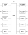
- FIG. 1 shows a carbon dioxide production system 10A according to the first embodiment of the present invention.
- the carbon dioxide production system 10A includes, as main components, a vaporizer 12, a reformer 14, a first fuel cell stack 16, a second fuel cell stack 18, a separation unit 20, a first heat exchanger 30, a second A heat exchanger 32, a combustor 40, a water tank 42, a suction pump 44, a PSA (Pressure Swing Adsorption) device 46, and a carbon dioxide recovery tank 48 are provided. Further, as shown in FIG. 2, a control unit 50 for controlling the carbon dioxide production system 10A is provided.
- a raw material gas pipe P1 is connected to the reformer 14, and the other end of the raw material gas pipe P1 is connected to a gas source (not shown). From the gas source, methane is sent to the reformer 14 by the raw material supply blower B1.
- methane is used as the raw material gas, but it is not particularly limited as long as it can be reformed, and a hydrocarbon fuel can be used.
- the hydrocarbon fuel include natural gas, LP gas (liquefied petroleum gas), coal reformed gas, lower hydrocarbon gas, and the like.
- Examples of the lower hydrocarbon gas include lower hydrocarbons having 4 or less carbon atoms such as methane, ethane, ethylene, propane, and butane, and methane used in the present embodiment is preferable.
- the hydrocarbon fuel may be a mixture of the above-described lower hydrocarbon gas, and the above-described lower hydrocarbon gas may be a gas such as natural gas, city gas, or LP gas.
- the water supply pipe P2 is connected to the vaporizer 12, and water (liquid phase) is fed by the water supply pump PO1.
- water In the vaporizer 12, water is vaporized.
- the heat of the combustor 40 described later is used.
- Steam is delivered from the vaporizer 12, and the steam pipe P3 that delivers the steam joins the raw material gas pipe P1.
- Methane and water vapor are merged in the raw material gas pipe P 1 and supplied to the reformer 14.
- the reformer 14 is adjacent to the combustor 40, the first fuel cell stack 16, and the second fuel cell stack 18, and is heated by exchanging heat with them.
- the reformer 14 reforms methane to produce fuel gas containing hydrogen and having a temperature of about 600 ° C.
- the reformer 14 is connected to the anode (fuel electrode) 16 ⁇ / b> A of the first fuel cell stack 16.
- the fuel gas generated by the reformer 14 is supplied to the anode 16A of the first fuel cell stack 16 via the fuel gas pipe P4.
- the raw material gas component that has not been reacted in the reformer 14 is also contained in the fuel gas and supplied to the anode 16A.
- the first fuel cell stack 16 is a solid oxide fuel cell stack, and has a plurality of stacked fuel cells.
- the first fuel cell stack 16 is an example of a fuel cell (first fuel cell) according to the present invention.
- the operating temperature is about 650 ° C.
- Each fuel cell has an electrolyte layer 16C, and an anode 16A and a cathode (air electrode) 16B laminated on the front and back surfaces of the electrolyte layer 16C.
- the basic configuration of the second fuel cell stack 18 is the same as that of the first fuel cell stack 16, and corresponds to the anode 18A corresponding to the anode 16A, the cathode 18B corresponding to the cathode 16B, and the electrolyte layer 16C. It has an electrolyte layer 18C.
- the oxidant gas (air) is supplied from the oxidant gas pipe P5 to the cathode 16B of the first fuel cell stack 16. Air is introduced into the oxidant gas pipe P5 by the oxidant gas blower B2.
- the oxidant gas pipe P5 is provided with a second heat exchanger 32, and air is heated by heat exchange with a non-fuel gas to be described later and supplied to the cathode 16B.
- oxygen and electrons in the oxidant gas react to generate oxygen ions.
- the generated oxygen ions reach the anode 16A of the first fuel cell stack 16 through the electrolyte layer.
- the cathode 16B is connected to a cathode offgas pipe P6 that guides the cathode offgas discharged from the cathode 16B to the cathode 18B of the second fuel cell stack 18.
- anode 16A of the first fuel cell stack 16 As shown in the following equations (2) and (3), oxygen ions that have passed through the electrolyte layer react with hydrogen and carbon monoxide in the fuel gas. Water (steam) and carbon dioxide and electrons are generated. Electrons generated at the anode 16A move from the anode 16A through the external circuit to the cathode 16B, and are thus generated in each fuel cell. Each fuel cell generates heat during power generation.
- a power meter E1 is connected to the power cable 16D that extracts power from the first fuel cell stack 16. The power output from the first fuel cell stack 16 is measured by the wattmeter E1. The amount of power generated in the first fuel cell stack 16 is controlled by the control unit 50.
- anode offgas pipe P7 One end of an anode offgas pipe P7 is connected to the anode 16A of the first fuel cell stack 16, and the anode offgas is discharged from the anode 16A to the anode offgas pipe P7.
- the anode off gas contains unreformed raw material gas components, unreacted hydrogen, unreacted carbon monoxide, carbon dioxide, water vapor, and the like.
- the fuel cell of the present invention is not limited to a solid oxide fuel cell (SOFC), but is another fuel cell in which carbon dioxide is contained in the anode off gas, for example, molten carbonate.
- SOFC solid oxide fuel cell
- a fuel cell (MCFC), a phosphoric acid fuel cell (PAFC), and a polymer electrolyte fuel cell (PEFC) may be used.
- the other end of the anode off gas pipe P7 is connected to the inflow part 24 of the separation part 20 via a first heat exchanger 30 described later.
- the separation unit 20 separates carbon dioxide and water from the anode off gas by a separation membrane 28 described later.
- the separation unit 20 includes an inflow portion 24 and a transmission portion 26.
- the inflow part 24 and the permeation part 26 are partitioned by a separation membrane 28.
- the inflow part 24 becomes the non-permeation side of the anode off gas, and the permeation part 26 becomes the permeation side.
- the separation membrane 28 has a function of transmitting carbon dioxide and water.
- the material is not particularly limited as long as it has a function of transmitting carbon dioxide and water, and examples thereof include an organic polymer film, an inorganic material film, an organic polymer-inorganic material composite film, and a liquid film.
- the anode off gas is supplied to the inflow section 24 of the separation section 20 through the anode off gas pipe P7. Carbon dioxide and water contained in the anode off gas pass through the separation membrane 28 and move to the permeation unit 26. The anode off gas remaining on the inflow portion 24 side after the concentration of carbon dioxide and water is reduced becomes regenerated fuel gas and is sent out from the inflow portion 24.
- the regenerated fuel gas pipe P9 is connected to the anode 18A of the second fuel cell stack 18, and the regenerated fuel gas is supplied to the anode 18A of the second fuel cell stack 18 via the regenerated fuel gas pipe P9. .
- Heat exchange is performed in the first heat exchanger 30 between the anode off gas flowing through the anode off gas pipe P7 and the regenerated fuel gas flowing through the regenerated fuel gas pipe P9.
- the anode off gas is cooled and the regenerated fuel gas is heated.
- the other end of the non-fuel gas pipe P16 having one end connected to the water tank 42 is connected to the permeation section 26 of the separation section 20.
- carbon dioxide and water move from the inflow portion 24 through the separation membrane 28 to the permeation portion 26.
- Carbon dioxide, water (gas phase), and other gases in the anode off-gas that have passed through the separation membrane 28 are sent out from the permeation unit 26 as non-fuel gas.
- the sent non-fuel gas is sent to the water tank 42 through the second heat exchanger 32 by the non-fuel gas pipe P16.
- water liquefied by condensation and a non-fuel gas (hereinafter referred to as “carbon dioxide rich gas”) in which water is removed and the main component is carbon dioxide are stored in a separated state.
- a recovery pipe P18 is connected to the gas storage part at the upper part of the water tank 42, and one end of a water circulation pipe P19 for supplying water to the vaporizer 12 is connected to the liquid storage part at the lower part of the water tank 42. Yes.
- the carbon dioxide rich gas is sent to the recovery pipe P18.
- a PSA device 46 is connected to the other end of the recovery pipe P18.
- components other than carbon dioxide are removed from the carbon dioxide rich gas by adsorption (hereinafter, this gas is referred to as “carbon dioxide gas”), and the gas is sent to the CO 2 pipe P20.
- One end of the CO2 pipe P20 is connected to the PSA device 46, and the other end of the CO2 pipe P20 is connected to the carbon dioxide recovery tank 48.
- the carbon dioxide gas delivered from the PSA device 46 is stored in the carbon dioxide recovery tank 48 through the CO2 pipe P20.
- a flow meter 48 ⁇ / b> A is provided at the inlet of the carbon dioxide recovery tank 48.
- the flow rate of the gas flowing into the carbon dioxide recovery tank 48 is measured by the flow meter 48A.
- the CO2 pipe P20 may be connected to a pipe for supplying to another system. Further, the filling amount and pressure of the carbon dioxide recovery tank 48 may be measured.
- the suction pump 44 is connected to the collection pipe P18.
- the suction pump 44 sucks the upstream gas and sends it to the downstream side.
- the non-fuel gas is sucked from the permeation unit 26 by the suction pump 44 and sent to the PSA device 46 at a predetermined pressure.
- the flow rate of the non-fuel gas that passes through the separation membrane 28 from the inflow portion 24 and moves to the permeation portion 26 is controlled.
- the branch pipe P21 is connected downstream of the suction pipe 44 of the recovery pipe P18.
- the branch pipe P21 is provided with an on-off valve V1.
- an on-off valve V2 is provided downstream of the portion of the recovery pipe P18 to which the branch pipe P21 is connected.
- the carbon dioxide rich gas sent to the recovery pipe P18 is sent to the PSA device 46 when the on-off valve V1 is closed and the on-off valve V2 is opened.
- the carbon dioxide rich gas is sent to the branch pipe P21 when the on-off valve V1 is opened and the on-off valve V2 is closed.
- the branch pipe P21 is open to the outside.
- the carbon dioxide recovery tank 48 cannot be filled with carbon dioxide or when it is desired to stop the carbon dioxide recovery, the carbon dioxide rich gas can be sent to the branch pipe P21 and released to the outside. Normally, the carbon dioxide rich gas is delivered to the PSA device 46.
- the second heat exchanger 32 heat exchange is performed between the non-fuel gas and air, the air is heated, and the non-fuel gas is cooled.
- the water vapor in the cooled non-fuel gas is condensed and flows into the water tank 42 and stored.
- the carbon dioxide rich gas from which the water vapor is separated and the carbon dioxide concentration is increased is sent out from the recovery pipe P18 and is recovered in the carbon dioxide recovery tank 48 via the PSA device 46.
- power is generated by the same reaction as that of the first fuel cell stack 16.
- a power meter E ⁇ b> 2 is connected to the power cable 18 ⁇ / b> D that extracts power from the second fuel cell stack 18.
- the power output from the second fuel cell stack 18 is measured by the wattmeter E2.
- the amount of power generated in the first fuel cell stack 16 is controlled by the control unit 50.
- the spent gas discharged from the anode 18A and the cathode 18B is sent to the combustor 40 through the pipe P11 and the cathode off combustion introduction pipe P12, and is used for incineration in the combustor 40.
- the carbon dioxide production system 10A of the present embodiment is a multi-stage type in which the anode off-gas that is the fuel used in the first fuel cell stack 16 is regenerated and reused as the fuel gas in the second fuel cell stack 18. It is a carbon dioxide production system.
- Combustion exhaust gas is sent from the combustor 40.
- the combustion exhaust gas flows through the combustion exhaust pipe P10 and is discharged through the vaporizer 12.
- the control unit 50 controls the entire carbon dioxide production system 10A, and includes a CPU, a ROM, a RAM, a memory, and the like.
- the memory stores data and procedures necessary for a carbon dioxide flow rate adjusting process, which will be described later, and a process during normal operation.
- the control unit 50 includes a raw material supply blower B1, a water supply pump PO1, a suction pump 44, a first fuel cell stack 16, and a second fuel cell stack 18, wattmeters E1, E2,
- the flowmeter 48A and the PSA device 46 are connected.
- the output of the raw material supply blower B1, the water supply pump PO1, the oxidant gas blower B2, the suction pump 44, and the PSA device 46 is controlled by the control unit 50.
- methane which is fuel from a gas source
- water from the water tank 42 are supplied to the vaporizer 12.
- the supplied methane and water are mixed, and heat is obtained from the combustion exhaust gas flowing through the combustion exhaust pipe P ⁇ b> 10, and the water is vaporized to become steam.
- Methane and water vapor are sent from the vaporizer 12 to the reformer 14 via the pipe P1.
- a fuel gas containing about 600 ° C. containing hydrogen is generated by the steam reforming reaction.
- the fuel gas is supplied to the anode 16A of the first fuel cell stack 16 through the fuel gas pipe P4.
- the air is supplied to the cathode 16B of the first fuel cell stack 16 through the oxidant gas pipe P5.
- the anode off gas is discharged from the anode 16A of the fuel cell stack 16.
- the cathode off gas is discharged from the cathode 16B.
- the cathode off gas is supplied to the cathode 18B of the second fuel cell stack 18 through the cathode off gas pipe P6.
- the anode off gas discharged from the anode 16A is guided to the anode off gas pipe P7, and flows into the inflow section 24 of the separation section 20 through the first heat exchanger 30.
- the temperature of the anode off gas decreases from about 650 ° C. to a certain degree, for example, about 200 ° C.
- the temperature here is a temperature at which the gas phase state of water in the anode off-gas is maintained.
- Carbon dioxide and water (gas phase) in the anode off-gas are separated by passing through the separation membrane 28 and moving to the permeation section 26 side.
- Regenerated fuel gas is sent out from the inflow portion 24, is heated to about 600 ° C. through the first heat exchanger 30, and is supplied to the anode 18A of the second fuel cell stack 18 through the regenerated fuel gas pipe P9.
- the spent gas at the anode 18A and the cathode 18B is sent to the combustor 40 through the pipes P11 and P12, and is used for incineration by the combustor 40.
- the combustion exhaust gas from the combustor 40 is exhausted through heat exchange in the vaporizer 12.
- the suction pump 44 sucks non-fuel gas from the permeation section 26 with a predetermined output.
- the output of the suction pump 44 here is set according to the amount of power generation required in the carbon dioxide production system 10A.
- the non-fuel gas passes through the separation membrane 28 and flows into the permeation unit 26 and is sent out from the permeation unit 26.
- the sent non-fuel gas is cooled by the second heat exchanger 32 by heat exchange with the air passing through the oxidant gas pipe P5.
- the water vapor in the non-fuel gas is condensed and separated from the non-fuel gas.
- Non-fuel gas and condensed water are sent to the water tank 42.
- the carbon dioxide rich gas from which water has been separated from the non-fuel gas is sent from the water tank 42 to the recovery pipe P18, sent to the PSA device 46, and recovered to the carbon dioxide recovery tank 48 via the PSA device 46.
- water is condensed by heat exchange in the second heat exchanger 32 after the carbon dioxide and water (gas phase) are separated by the separation membrane 28, so that the separation by the separation membrane is performed.
- it can be made to send out from the inflow part 24, maintaining the temperature of regeneration fuel gas high. Therefore, the regenerated fuel gas for power generation in the second fuel cell stack 18 can be efficiently reused.
- the water vapor in the discharged non-fuel gas can be easily separated from the permeation unit 26 by condensation, and the non-fuel gas having a high carbon dioxide concentration can be recovered.
- step S10 the measurement (flow rate measurement value) of the flow meter 48A is acquired, and in step S12, it is compared with the set value.
- step S14 the output of the suction pump 44 is adjusted based on the comparison result between the flow rate measurement value and the set value. In the adjustment, when the flow rate measurement value is smaller than the set value, the output of the suction pump 44 is increased to increase the amount of non-fuel gas that permeates the separation membrane 28, and the flow rate measurement value is larger than the set value. For this, the output of the suction pump 44 is lowered to reduce the amount of non-fuel gas that permeates the separation membrane 28.
- the flow rate of the carbon dioxide gas recovered by the carbon dioxide recovery tank 48 can be set to a desired setting range.
- the end of the process is input from the input unit.
- step S16 it is determined whether or not an end input has been received. If the determination is affirmative, the carbon dioxide flow rate adjusting process is ended.
- the output of the suction pump 44 by adjusting the output of the suction pump 44, the flow rate of the carbon dioxide gas recovered in the carbon dioxide recovery tank 48 is brought close to the set value, but the output of the raw material supply blower B1 and the water supply pump PO1. May be adjusted.
- all of the suction pump 44, the raw material supply blower B1, and the water supply pump PO1 may be adjusted, or may be adjusted by a combination of any of a plurality of devices.
- the pressure in the carbon dioxide recovery tank 48 may be measured, or the filling amount may be measured.
- the output of the raw material supply blower B1 when the flow rate measurement value is smaller than the set value, the output of the raw material supply blower B1 is increased to increase the flow rate of the anode off gas flowing into the separation unit 20, This increases the amount of non-fuel gas that permeates the separation membrane 28. Further, when the flow rate measurement value is larger than the set value, the output of the raw material supply blower B1 is lowered to reduce the flow rate of the anode off gas flowing into the separation unit 20, and thereby the non-fuel that permeates the separation membrane 28. Reduce the amount of gas. When adjusting the output of the raw material supply blower B1, the amount of power generation is also adjusted as appropriate.
- the output of the water supply pump PO1 when adjusting the output of the water supply pump PO1, if the measured flow rate is smaller than the set value, the output of the water supply pump PO1 is increased and the flow rate of the anode off gas flowing into the separation unit 20 is increased. Thus, the amount of non-fuel gas that permeates the separation membrane 28 is increased. Further, when the flow rate measurement value is larger than the set value, the output of the water supply pump PO1 is lowered to reduce the flow rate of the anode off gas flowing into the separation unit 20, and thereby the non-fuel that permeates the separation membrane 28. Reduce the amount of gas.
- the power generation amount in the carbon dioxide production system 10A may be adjusted so that the flow rate of the carbon dioxide gas recovered in the carbon dioxide recovery tank 48 approaches the set value.
- the amount of power generation is the total power generated by the carbon dioxide production system 10A (the sum of the power generated by the first fuel cell stack 16 and the power generated by the second fuel cell stack 18, that is, the wattmeter E1 Or the measured value E2 of the wattmeter E2), or based on the power generated by the first fuel cell stack 16 (measured value of the wattmeter E1). You may adjust.
- the power generation amount in the first fuel cell stack 16 and the second fuel cell stack 18 When adjusting with the whole electric power generated with the carbon dioxide production system 10A, when the flow rate measurement value is smaller than the set value, the power generation amount in the first fuel cell stack 16 and the second fuel cell stack 18 The sum of the power generation amount at (the sum of the measured value at the wattmeter E1 and the measured value E2 at the wattmeter E2) is increased. On the other hand, when the flow rate measurement value is larger than the set value, the sum of the power generation amount in the first fuel cell stack 16 and the power generation amount in the second fuel cell stack 18 (measurement value and power in the wattmeter E1). The sum of the measured values E2 in the total E2) is decreased.
- the electric power generated by the first fuel cell stack 16 is adjusted so as to obtain a desired flow rate of carbon dioxide, It is possible to adjust the electric power generated by the second fuel cell stack 18 so that the entire electric power generated by the carbon dioxide production system 10A becomes a desired value.
- the power generation amount (with the wattmeter E1) Increase the measured value).
- the power generation amount in the first fuel cell stack 16 (measurement value in the wattmeter E1) is decreased.
- the electric power generated with the 2nd fuel cell stack 18 may be adjusted, and in the 2nd fuel cell stack 18 It is good even if it does not adjust.
- the PSA device 46 is provided, but the PSA device 46 is not necessarily installed.
- the concentration of carbon dioxide recovered in the carbon dioxide recovery tank 48 can be adjusted by installing the PSA device 46 and adjusting the adsorption conditions for carbon dioxide and other components.
- carbon dioxide is recovered between the first fuel cell stack 16 and the second fuel cell stack 18 in one carbon dioxide production system.
- Carbon may be recovered. That is, an anode of a fuel cell stack is connected in series between a plurality of fuel cell systems, and is discharged from an anode of a fuel cell stack of an upstream fuel cell system and supplied to an anode of a downstream fuel cell system Carbon dioxide may be separated and recovered from the previous anode off gas.
- the carbon dioxide production system 10 ⁇ / b> B of this embodiment does not have the PSA device 46.
- the combustion exhaust gas discharged from the vaporizer 12 through the combustion exhaust gas pipe P10 is branched into a combustion exhaust gas exhaust pipe P10A and a temperature adjustment pipe P10B.
- the combustion exhaust gas is exhausted from the combustion exhaust gas exhaust pipe P10A.
- the temperature adjustment pipe P10B is connected to the upstream side of the oxidant gas blower B2.
- the temperature adjustment pipe P10B is provided with a flow rate adjustment valve 54, and the flow rate of the combustion exhaust gas sent to the oxidant gas blower B2 is adjusted by the opening degree.
- the flow rate adjusting valve 54 is connected to the control unit 50, and the opening degree is adjusted by the control unit 50.
- a composition detector 48B is provided at the inlet of the carbon dioxide recovery tank 48 in place of the flow meter 48A.
- the composition detector 48B can detect the carbon dioxide concentration of the gas flowing into the carbon dioxide recovery tank 48.
- the composition detector 48 ⁇ / b> B is connected to the control unit 50 and transmits the detected carbon dioxide concentration value to the control unit 50.
- the concentration of carbon dioxide recovered by the carbon dioxide recovery tank 48 can be adjusted.
- a desired carbon dioxide concentration value is input from an input unit (not shown).
- the input value (set value) is sent to the control unit 50, and the control unit 50 executes the carbon dioxide flow rate adjustment process shown in FIG.
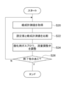
- step S20 the measurement value (composition measurement value) of the composition detector 48B is acquired, and in step S22, it is compared with the set value.
- step S24 the flow rate adjustment valve 54 or the oxidant gas blower B2 is adjusted based on the comparison result between the measured composition value and the set value.
- the flow rate adjustment valve 54 is closed to increase the output of the oxidant gas blower B2.
- the flow rate of the oxidant gas passing through the oxidant gas pipe P5 increases, the water vapor condensed by the heat exchange in the second heat exchanger 32 increases, and the carbon dioxide recovered in the carbon dioxide recovery tank 48
- the gas concentration increases.
- the flow rate adjustment valve 54 is opened.
- the temperature of the oxidant gas passing through the oxidant gas pipe P ⁇ b> 5 rises, the water vapor condensed by heat exchange in the second heat exchanger 32 decreases, and the carbon dioxide recovered in the carbon dioxide recovery tank 48.
- the gas concentration is lowered.
- the concentration of the carbon dioxide gas recovered in the carbon dioxide recovery tank 48 can be set to a desired setting range by feedback control of the oxidant gas blower B2 and the flow rate adjusting valve 54 based on the composition measurement value. it can.
- the end of the process is input from the input unit.
- step S26 it is determined whether or not an end input has been received. If the determination is affirmative, the carbon dioxide concentration adjustment process is ended.
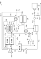
- FIG. 7 shows a carbon dioxide production system 10C according to the third embodiment of the present invention.
- the carbon dioxide production system 10C is different from the carbon dioxide production system 10A described in the first embodiment in that the second fuel cell stack 18 is not provided.
- the regenerated fuel gas pipe P9 connected to the separation unit 20 is branched at a branching portion D1 provided on the upstream side of the first heat exchanger 30.
- One of the branched circulation gas pipes P9-1 is connected to the pipe P1 via the first heat exchanger 30.
- the other branched regenerative fuel gas pipe P9-2 is connected to the combustor 40.
- the branch portion D1 the regenerated fuel gas is divided into the circulation gas pipe P9-1 and the regenerated fuel gas pipe P9-2.
- the regenerated fuel gas introduced into the reformer 14 via the circulating gas pipe P9-1 is mixed with methane and water vapor supplied from the vaporizer 12, and supplied to the reformer 14.
- the regenerated fuel gas introduced into the combustor 40 through the regenerated fuel gas pipe P9-2 is burned in the combustor 40.
- the cathode offgas discharged from the cathode 16B is introduced into the combustor 40 via the cathode offgas pipe P6.
- the anode off-gas that is the spent fuel in the first fuel cell stack 16 is regenerated and reused in the first fuel cell stack 16 again. It is a carbon production system. In this embodiment, the same effect as that of the first embodiment can be obtained.
- FIG. 8 shows a carbon dioxide production system 10D according to the fourth embodiment of the present invention. Similarly to the carbon dioxide production system 10C described in the third embodiment, the carbon dioxide production system 10D regenerates the anode off-gas that is the spent fuel in the first fuel cell stack 16, and again the first fuel cell. This is a circulating carbon dioxide production system that is reused in the cell stack 16.
- the carbon dioxide production system 10D does not have the PSA device 46 as in the second embodiment, as compared with the carbon dioxide production system 10C described in the third embodiment.
- the combustion exhaust gas discharged from the vaporizer 12 through the combustion exhaust gas pipe P10 is branched into a combustion exhaust gas exhaust pipe P10A and a temperature adjustment pipe P10B.
- the combustion exhaust gas is exhausted from the combustion exhaust gas exhaust pipe P10A.
- the temperature adjustment pipe P10B is connected to the upstream side of the oxidant gas blower B2.
- the temperature adjustment pipe P10B is provided with a flow rate adjustment valve 54, and the flow rate of the combustion exhaust gas sent to the oxidant gas blower B2 is adjusted by the opening degree.
- the present invention is not limited to the first to fourth embodiments described above, and is implemented by a person skilled in the art in combination with the above-described embodiments within the technical idea of the present invention.
- the installation position and combination of the heat exchanger, the blower, and the pump are not limited to these embodiments.
- the carbon dioxide recovery tank 48 may contain a carbon dioxide absorbent or adsorbent. Further, it may be a carbon dioxide liquefying device or a carbon dioxide solidifying device.
- a hydrocarbon raw material such as methane is reformed by the reformer 14 to obtain a fuel gas.
- a fuel gas containing a carbon compound may be generated outside and supplied to the fuel cell system. Good.
- Carbon compounds include carbon monoxide in addition to hydrocarbons such as methane.
- a hydrocarbon raw material such as methane may be directly supplied to the first fuel cell stack 16 as a fuel gas to generate electric power.
Landscapes
- Chemical & Material Sciences (AREA)
- Engineering & Computer Science (AREA)
- Chemical Kinetics & Catalysis (AREA)
- General Chemical & Material Sciences (AREA)
- Electrochemistry (AREA)
- Sustainable Development (AREA)
- Sustainable Energy (AREA)
- Manufacturing & Machinery (AREA)
- Life Sciences & Earth Sciences (AREA)
- Analytical Chemistry (AREA)
- Oil, Petroleum & Natural Gas (AREA)
- Combustion & Propulsion (AREA)
- Organic Chemistry (AREA)
- Fuel Cell (AREA)
- Inorganic Chemistry (AREA)
- Separation Using Semi-Permeable Membranes (AREA)
- Separation Of Gases By Adsorption (AREA)
Abstract
二酸化炭素製造システム10Aは、燃料電池セルスタック16と、アノードオフガスを、少なくとも二酸化炭素及び水を含む非燃料ガスと再生燃料ガスとに分離する分離部20と、非燃料ガスから水を分離する第2熱交換器32、水タンク42と、水が分離された後の二酸化炭素を回収する二酸化炭素回収タンク48を備えている。
Description
本発明は二酸化炭素製造システムに関する。
燃料電池システムにおいて、炭素化合物燃料を用いる場合には、二酸化炭素が発生する。この二酸化炭素は、アノードから排出されるアノードオフガスにも含まれており、アノードオフガスを再生燃料として発電に供する場合には、アノードオフガスから二酸化炭素を除去することが行われる。
例えば、特開平6-203845号公報には、アノードオフガスを凝縮させて水蒸気を分離し、水蒸気が分離されたアノードオフガスを二酸化炭素分離装置へ導入し、分離膜により二酸化炭素を分離して回収する技術が開示されている。
カソードオフガスが混ざる燃焼排ガスと比較して、二酸化炭素濃度が高い燃料電池システムのアノードオフガスから二酸化炭素を分離して回収することで、容易に高濃度の二酸化炭素を回収することができる。この場合、再生燃料ガスを効率的に発電に再利用すると共に、二酸化炭素の回収にも工夫が求められる。
本発明は上記事実を考慮して成されたもので、アノードオフガスから二酸化炭素を容易に分離すると共に、発電用の再生燃料ガスを効率的に再利用することが目的である。
本発明の第1の態様に係る二酸化炭素製造システムは、炭素化合物を含み燃料極へ供給される燃料ガスと、酸素を含み空気極へ供給される酸化剤ガスと、により発電し、前記燃料極からアノードオフガスが排出される燃料電池と、前記アノードオフガスを、少なくとも二酸化炭素及び水を含む非燃料ガスと再生燃料ガスとに分離する分離部と、前記非燃料ガスから水を分離する水分離部と、前記水分離部で水が分離された後の二酸化炭素を回収する二酸化炭素回収部と、を備えている。
第1の態様に係る二酸化炭素製造システムでは、燃料極へ供給された燃料ガスと空気極へ供給された酸化剤ガスにより、燃料電池での発電が行われる。燃料ガスには、炭素化合物が含まれており、燃料極からは少なくとも二酸化炭素及び水を含むアノードオフガスが排出される。なお、ここでの燃料ガスは、炭素化合物を含むものであれば特に限定されず、例えば、炭化水素化合物を改質して得られる改質ガスであっても、炭化水素化合物そのものであっても、一酸化炭素そのものであってもよい。
分離部は、アノードオフガスを、少なくとも二酸化炭素及び水を含む非燃料ガスと再生燃料ガスとに分離する。凝縮により水を分離する場合と比較して、再生燃料ガスを高温に維持できるので、熱エネルギーのロスを少なくして効率的に再生燃料ガスを発電に供することができる。また、アノードオフガスから二酸化炭素のみを分離する場合と比較して、分離手段の選択の自由度を高くすることができる。
非燃料ガスは、水分離部で水が分離され、水が分離された後の非燃料ガスを二酸化炭素回収部で回収する。再生燃料ガスと分離した後の非燃料ガスでは、水と二酸化炭素が主成分となっているので、凝縮により容易に水を分離することができる。
本発明の第2の態様に係る二酸化炭素製造システムは、前記分離部から送出される前記再生燃料ガスを用いて発電する第2燃料電池を備えている。
第2の態様に係る二酸化炭素製造システムによれば、再生燃料ガスを用いて第2燃料電池で発電するので、発電効率を高めることができる。
本発明の第3の態様に係る二酸化炭素製造システムは、前記分離部は、前記非燃料ガスを透過させる分離膜により非透過側と透過側とに区画され、前記透過側から前記非燃料ガスを吸引して前記二酸化炭素回収部へ送出させる吸引ポンプを備えている。
第3の態様に係る二酸化炭素製造システムによれば、吸引ポンプでの吸引を行うことにより、非燃料ガスの透過側への透過を促進することができる。
本発明の第4の態様に係る二酸化炭素製造システムは、炭素化合物を含み燃料極へ供給される燃料ガスと、酸素を含み空気極へ供給される酸化剤ガスと、により発電し、前記燃料極からアノードオフガスが排出される燃料電池と、前記アノードオフガスを、少なくとも二酸化炭素を含む非燃料ガスと再生燃料ガスとに分離する分離部と、前記分離部で分離された後の非燃料ガスを回収する二酸化炭素回収部と、前記二酸化炭素回収部で回収される非燃料ガス中の二酸化炭素の濃度及び非燃料ガスの流量の少なくとも一方が設定範囲となるように調整する二酸化炭素調整部と、を備えている。
第4の態様に係る二酸化炭素製造システムでは、燃料極へ供給された燃料ガスと空気極へ供給された酸化剤ガスにより、燃料電池での発電が行われる。燃料ガスには、炭素化合物が含まれており、燃料極からは少なくとも二酸化炭素及び水を含むアノードオフガスが排出される。分離部は、アノードオフガスを、少なくとも二酸化炭素を含む非燃料ガスと再生燃料ガスとに分離する。そして、二酸化炭素調整部によって、二酸化炭素回収部で回収される非燃料ガス中の二酸化炭素の濃度及び非燃料ガスの流量の少なくとも一方が、設定範囲となるように調整される。これにより、所望の設定範囲での濃度、流量の二酸化炭素を回収することができる。
本発明の第5の態様係る二酸化炭素製造システムは、前記分離部から送出される前記再生燃料ガスを用いて発電する第2燃料電池を備えている。
第5の態様に係る二酸化炭素製造システムによれば、再生燃料ガスを用いて第2燃料電池で発電するので、発電効率を高めることができる。
本発明の第6の態様に係る二酸化炭素製造システムは、前記二酸化炭素調整部は、前記燃料電池での発電量を調整すること、を特徴とする。
第6の態様に係る二酸化炭素製造システムによれば、燃料電池での発電量を調整することにより、アノードオフガス中の二酸化炭素濃度、二酸化炭素流量が変わることから、二酸化炭素回収部で回収する時間当たりの二酸化炭素の量や濃度を調整することができる。
本発明の第7の態様に係る二酸化炭素製造システムは、前記二酸化炭素調整部は、システム全体における発電量を調整すること、を特徴とする。
第7の態様に係る二酸化炭素製造システムによれば、システム全体における発電量を調整することにより、アノードオフガス中の二酸化炭素濃度、二酸化炭素流量が変わることから、二酸化炭素回収部で回収する時間当たりの二酸化炭素の量や濃度を調整することができる。
本発明の第8の態様に係る二酸化炭素製造システムは、前記分離部は、前記アノードオフガスを、少なくとも二酸化炭素及び水を含む非燃料ガスと再生燃料ガスとに分離し、前記非燃料ガスから水を分離する水分離部、を更に備えている。
第8の態様に係る二酸化炭素製造システムによれば、凝縮により水を分離する場合と比較して、再生燃料ガスを高温に維持できるので、効率的に再生燃料ガスを発電に供することができる。また、アノードオフガスから二酸化炭素のみを分離する場合と比較して、分離手段の選択肢を広げることができる。
非燃料ガスは、水分離部で水が分離され、水が分離された後の非燃料ガスを二酸化炭素回収部で回収する。再生燃料ガスと分離した後の非燃料ガスでは、水と二酸化炭素が主成分となっているので、水を分離するための手段の選択肢を広げることができる。
本発明の第9の態様に係る二酸化炭素製造システムは、前記水分離部は、凝縮により前記非燃料ガスから水蒸気を除去し、前記二酸化炭素調整部は、前記水分離部での凝縮量を調整すること、を特徴とする。
第9の態様に係る二酸化炭素製造システムによれば、水分離部での凝縮量を調整することにより、二酸化炭素回収部で回収する二酸化炭素の濃度を調整することができる。
本発明の第10の態様に係る二酸化炭素製造システムは、前記水分離部の下流側に圧力スイング吸着部を有し、前記濃度調整部は、前記圧力スイング吸着部における吸着条件を調整すること、を特徴とする。
第10の態様に係る二酸化炭素製造システムによれば、圧力スイング吸着部における吸着条件を調整することにより、二酸化炭素回収部で回収する二酸化炭素の濃度を調整することができる。
本発明の第11の態様に係る二酸化炭素製造システムは、前記二酸化炭素調整部は、前記燃料極へ送出する前記燃料ガス量を調整すること、を特徴とする。
第11の態様に係る二酸化炭素製造システムによれば、燃料極へ送出する前記燃料ガス量を調整することにより、アノードオフガス中の二酸化炭素濃度、二酸化炭素流量が変わることから、二酸化炭素回収部で回収する時間当たりの二酸化炭素の量や濃度を調整することができる。
本発明の第12の態様に係る二酸化炭素製造システムは、原料ガスを改質して前記燃料ガスを生成する改質器を有し、前記二酸化炭素調整部は、前記改質器へ供給する改質水の量を調整すること、を特徴とする。
第12の態様に係る二酸化炭素製造システムによれば、改質器へ供給する改質水の量を調整することにより、二酸化炭素回収部で回収する時間当たりの二酸化炭素の量や濃度を調整することができる。
本発明の第13の態様に係る二酸化炭素製造システムは、前記分離部は、前記非燃料ガスを透過させる分離膜により非透過側と透過側とに区画され、前記透過側から前記非燃料ガスを吸引して前記二酸化炭素回収部へ送出させる吸引ポンプを備えている。
第13の態様に係る二酸化炭素製造システムによれば、吸引ポンプで透過側の圧力を下げることにより、二酸化炭素の濃度を下げることなく二酸化炭素を回収することができる。
本発明の第14の態様に係る二酸化炭素製造システムは、前記分離部は、前記非燃料ガスを透過させる分離膜により非透過側と透過側とに区画され、前記透過側から前記非燃料ガスを吸引して前記二酸化炭素回収部へ送出させる吸引ポンプを備え、前記二酸化炭素調整部は、前記吸引ポンプでの吸引流量を調整すること、を特徴とする。
第14の態様に係る二酸化炭素製造システムによれば、吸引ポンプでの吸引流量を調整することにより、二酸化炭素回収部で回収する二酸化炭素の流量を調整することができる。
本発明に係る二酸化炭素製造システムによれば、アノードオフガスから二酸化炭素を効率よく分離すると共に、発電用の再生燃料ガスを効率的に再利用することができる。
以下、図面を参照して本発明の実施形態の一例を詳細に説明する。
〔第1実施形態〕
図1には、本発明の第1実施形態に係る二酸化炭素製造システム10Aが示されている。二酸化炭素製造システム10Aは、主要な構成として、気化器12、改質器14、第1燃料電池セルスタック16、第2燃料電池セルスタック18、分離部20、第1熱交換器30、第2熱交換器32、燃焼器40、水タンク42、吸引ポンプ44、PSA(Pressure Swing Adsorption)装置46、及び二酸化炭素回収タンク48を備えている。また、図2に示されるように、二酸化炭素製造システム10Aを制御する制御部50を備えている。
図1には、本発明の第1実施形態に係る二酸化炭素製造システム10Aが示されている。二酸化炭素製造システム10Aは、主要な構成として、気化器12、改質器14、第1燃料電池セルスタック16、第2燃料電池セルスタック18、分離部20、第1熱交換器30、第2熱交換器32、燃焼器40、水タンク42、吸引ポンプ44、PSA(Pressure Swing Adsorption)装置46、及び二酸化炭素回収タンク48を備えている。また、図2に示されるように、二酸化炭素製造システム10Aを制御する制御部50を備えている。
改質器14には、原料ガス管P1の一端が接続されており、原料ガス管P1の他端は図示しないガス源に接続されている。ガス源からは、原料供給ブロワB1によりメタンが改質器14へ送出される。なお、本実施形態では、原料ガスとしてメタンを用いるが、改質が可能なガスであれば特に限定されず、炭化水素燃料を用いることができる。炭化水素燃料としては、天然ガス、LPガス(液化石油ガス)、石炭改質ガス、低級炭化水素ガスなどが例示される。低級炭化水素ガスとしては、メタン、エタン、エチレン、プロパン、ブタン等の炭素数4以下の低級炭化水素が挙げられ、本実施形態で用いるメタンが好ましい。なお、炭化水素燃料としては、上述した低級炭化水素ガスを混合したものであってもよく、上述した低級炭化水素ガスは天然ガス、都市ガス、LPガス等のガスであってもよい。
気化器12には、水供給管P2が接続されており、水供給ポンプPO1により、水(液相)が送り込まれる。気化器12では、水が気化される。気化には、後述する燃焼器40の熱が用いられる。気化器12からは、水蒸気が送出され、水蒸気を送出する水蒸気管P3は、原料ガス管P1と合流されている。
メタン及び水蒸気は原料ガス管P1で合流され、改質器14へ供給される。改質器14は、燃焼器40、第1燃料電池セルスタック16、及び第2燃料電池セルスタック18と隣接されており、これらとの間で熱交換を行うことで加熱される。
改質器14では、メタンを改質し、水素を含む600℃程度の温度の燃料ガスを生成する。改質器14は、第1燃料電池セルスタック16のアノード(燃料極)16Aと接続されている。改質器14で生成された燃料ガスは、燃料ガス管P4を介して第1燃料電池セルスタック16のアノード16Aに供給される。なお、改質器14で未反応の原料ガス成分も、燃料ガスに含まれてアノード16Aへ供給される。
第1燃料電池セルスタック16は固体酸化物形の燃料電池セルスタックであり、積層された複数の燃料電池セルを有している。第1燃料電池セルスタック16は本発明における燃料電池(第1燃料電池)の一例であり、本実施形態では、作動温度が650℃程度とされている。個々の燃料電池セルは、電解質層16Cと、当該電解質層16Cの表裏面にそれぞれ積層されたアノード16A、及びカソード(空気極)16Bと、を有している。
なお、第2燃料電池セルスタック18についての基本構成は、第1燃料電池セルスタック16と同様であり、アノード16Aに対応するアノード18A、カソード16Bに対応するカソード18B、及び電解質層16Cに対応する電解質層18Cを有している。
第1燃料電池セルスタック16のカソード16Bには、酸化剤ガス管P5から酸化剤ガス(空気)が供給される。酸化剤ガス管P5へは、酸化剤ガスブロワB2により空気が導入されている。酸化剤ガス管P5には、第2熱交換器32が設けられており、空気が後述する非燃料ガスとの熱交換により加熱され、カソード16Bへ供給される。
カソード16Bでは、下記(1)式に示すように、酸化剤ガス中の酸素と電子とが反応して酸素イオンが生成される。生成された酸素イオンは電解質層を通って第1燃料電池セルスタック16のアノード16Aに到達する。
(空気極反応)
1/2O2+2e- →O2- …(1)
1/2O2+2e- →O2- …(1)
また、カソード16Bには、カソード16Bから排出されるカソードオフガスを第2燃料電池セルスタック18のカソード18Bへ案内するカソードオフガス管P6が接続されている。
一方、第1燃料電池セルスタック16のアノード16Aでは、下記(2)式及び(3)式に示すように、電解質層を通ってきた酸素イオンが燃料ガス中の水素及び一酸化炭素と反応し、水(水蒸気)及び二酸化炭素と電子が生成される。アノード16Aで生成された電子がアノード16Aから外部回路を通ってカソード16Bに移動することで、各燃料電池セルにおいて発電される。また、各燃料電池セルは、発電時に発熱する。第1燃料電池セルスタック16から電力を取り出す電力ケーブル16Dには、電力計E1が接続されている。電力計E1により、第1燃料電池セルスタック16から出力される電力が計測される。第1燃料電池セルスタック16での発電量は、制御部50で制御されている。
(燃料極反応)
H2+O2- →H2O+2e- …(2)
CO+O2- →CO2+2e- …(3)
H2+O2- →H2O+2e- …(2)
CO+O2- →CO2+2e- …(3)
第1燃料電池セルスタック16のアノード16Aにはアノードオフガス管P7の一端が接続されており、アノードオフガス管P7には、アノード16Aからアノードオフガスが排出される。アノードオフガスには、未改質の原料ガス成分、未反応の水素、未反応の一酸化炭素、二酸化炭素及び水蒸気等が含まれている。
なお、本発明の燃料電池としては、固体酸化物形の燃料電池(SOFC:Solid Oxide Fuel Cell)に限られるものではなく、アノードオフガスに二酸化炭素及が含まれる他の燃料電池、例えば溶融炭酸塩形燃料電池(MCFC)、リン酸形燃料電池(PAFC)、高分子電解質形燃料電池(PEFC)であってもよい。
アノードオフガス管P7の他端は、後述する第1熱交換器30を経て分離部20の流入部24と接続されている。分離部20は、アノードオフガスから二酸化炭素及び水を後述する分離膜28で分離するものである。分離部20は、流入部24及び透過部26を有している。流入部24と透過部26は、分離膜28で区画されている。流入部24がアノードオフガスの非透過側となり、透過部26が透過側となる。
ここで、分離膜28について説明する。本実施形態では、分離膜28は二酸化炭素及び水を透過する機能を有するものを用いる。二酸化炭素及び水を透過する機能を有するものであれば、特に限定されないが、例えば、有機高分子膜、無機材料膜、有機高分子-無機材料複合膜、液体膜などが挙げられる。
アノードオフガスは、アノードオフガス管P7を経て分離部20の流入部24へ供給される。アノードオフガスに含まれる二酸化炭素及び水は、分離膜28を透過して透過部26へ移動する。二酸化炭素及び水の濃度が低減されて流入部24側に残ったアノードオフガスは、再生燃料ガスとなって、流入部24から送出される。再生燃料ガス管P9は、第2燃料電池セルスタック18のアノード18Aと接続されており、再生燃料ガスは、再生燃料ガス管P9を経て、第2燃料電池セルスタック18のアノード18Aに供給される。
アノードオフガス管P7を流れるアノードオフガスと再生燃料ガス管P9を流れる再生燃料ガスとは、第1熱交換器30で熱交換が行われる。第1熱交換器30では、アノードオフガスが冷却され、再生燃料ガスが加熱される。
分離部20の透過部26には、水タンク42に一端が接続された非燃料ガス管P16の他端が接続されている。
分離部20では、流入部24から分離膜28を透過して二酸化炭素及び水(気相)が透過部26へ移動する。
二酸化炭素、水(気相)、及び、その他分離膜28を透過したアノードオフガス中の気体は、非燃料ガスとして透過部26から送出される。送出された非燃料ガスは、非燃料ガス管P16により、第2熱交換器32を経て水タンク42へ送出される。
水タンク42には、凝縮により液化した水、及び、水が除去され主成分を二酸化炭素とする非燃料ガス(以下「二酸化炭素リッチガス」という)が分離された状態で貯留されている。水タンク42の上部の気体貯留部分には、回収管P18の一端が接続され、水タンク42の下部の液体貯留部分には、水を気化器12へ供給する水循環管P19の一端が接続されている。二酸化炭素リッチガスは、回収管P18へ送出される。
回収管P18の他端には、PSA装置46が接続されている。PSA装置46では、二酸化炭素リッチガスから二酸化炭素以外の成分が吸着により除去され(以下このガスを「二酸化炭素ガス」という)、CO2管P20へ送出する。CO2管P20の一端はPSA装置46に接続され、CO2管P20の一他端は二酸化炭素回収タンク48に接続されている。PSA装置46から送出された二酸化炭素ガスは、CO2管P20を経て二酸化炭素回収タンク48へ貯留される。二酸化炭素回収タンク48の入口には、流量計48Aが設けられている。流量計48Aにより、二酸化炭素回収タンク48へ流入する気体の流量が計測される。なお、CO2管P20は、別のシステムへ供給するための配管に接続されていてもよい。また、二酸化炭素回収タンク48の充填量や圧力を計測してもよい。
回収管P18には、吸引ポンプ44が接続されている。吸引ポンプ44は、上流側の気体を吸引して下流側へ送出する。吸引ポンプ44により、透過部26から非燃料ガスが吸引され、所定の圧力でPSA装置46へ送出される。吸引ポンプ44の出力に応じて、流入部24から分離膜28を透過して透過部26へ移動する非燃料ガスの流量が制御される。
回収管P18の吸引ポンプ44よりも下流側には、分岐管P21が接続されている。分岐管P21には、開閉弁V1が設けられている。また、回収管P18の分岐管P21が接続された部分よりも下流側には、開閉弁V2が設けられている。回収管P18へ送出された二酸化炭素リッチガスは、開閉弁V1が閉鎖され、開閉弁V2が開放されている時には、PSA装置46へ送出される。また、二酸化炭素リッチガスは、開閉弁V1が開放され、開閉弁V2が閉鎖されている時には、分岐管P21へ送出される。分岐管P21は、外部に開放されている。二酸化炭素回収タンク48へ二酸化炭素を充填することができない場合や、二酸化炭素の回収を停止したい場合などには、分岐管P21へ二酸化炭素リッチガスを送出して、外部へ放出させることができる。通常は、二酸化炭素リッチガスは、PSA装置46へ送出される。
第2熱交換器32では、非燃料ガスと空気とで熱交換が行われ、空気は加熱され、非燃料ガスは冷却される。冷却された非燃料ガス中の水蒸気は凝縮し、水タンク42へ流入して貯留される。水蒸気が分離され、二酸化炭素濃度が高くなった二酸化炭素リッチガスは、回収管P18から送出され、PSA装置46を経て二酸化炭素回収タンク48に回収される。
第2燃料電池セルスタック18のアノード18A及びカソード18Bでは、第1燃料電池セルスタック16と同様の反応により発電が行われる。第2燃料電池セルスタック18から電力を取り出す電力ケーブル18Dには、電力計E2が接続されている。電力計E2により、第2燃料電池セルスタック18から出力される電力が計測される。第1燃料電池セルスタック16での発電量は、制御部50で制御されている。
アノード18A及びカソード18Bから排出された使用済のガスは、配管P11、カソードオフ燃焼導入管P12により燃焼器40へ送出され、燃焼器40で焼却に供される。本実施形態の二酸化炭素製造システム10Aは、第1燃料電池セルスタック16で使用された燃料であるアノードオフガスが再生されて、燃料ガスとして第2燃料電池セルスタック18で再利用される多段式の二酸化炭素製造システムとなっている。
燃焼器40からは、燃焼排ガスが送出される。燃焼排ガスは、燃焼排ガス管P10内を流通し、気化器12を経て排出される。
制御部50は、二酸化炭素製造システム10Aの全体を制御するものであり、CPU、ROM、RAM、メモリ等を含んで構成されている。メモリには、後述する二酸化炭素流量整処理や、通常運転時の処理に必要なデータや手順等が記憶されている。図2に示されるように、制御部50は、原料供給ブロワB1、水供給ポンプPO1、吸引ポンプ44、第1燃料電池セルスタック16、及び第2燃料電池セルスタック18、電力計E1、E2、流量計48A、及びPSA装置46と接続されている。原料供給ブロワB1、水供給ポンプPO1、酸化剤ガスブロワB2、吸引ポンプ44、及び、PSA装置46は、制御部50により出力が制御される。
次に、本実施形態の二酸化炭素製造システム10Aの動作について説明する。
二酸化炭素製造システム10Aにおいては、ガス源からの燃料であるメタン及び水タンク42からの水が、気化器12へ供給される。気化器12では、供給されたメタン及び水が混合されると共に、燃焼排ガス管P10を流通する燃焼排ガスから熱を得て加熱され、水が気化され水蒸気となる。
メタン及び水蒸気は、気化器12から配管P1を介して改質器14へ送出される。改質器14では、水蒸気改質反応により、水素を含む600℃程度の燃料ガスが生成される。燃料ガスは、燃料ガス管P4を介して第1燃料電池セルスタック16のアノード16Aに供給される。
第1燃料電池セルスタック16のカソード16Bには、空気が酸化剤ガス管P5を経て供給される。これにより、第1燃料電池セルスタック16では、前述の反応により発電が行われる。この発電に伴い燃料電池セルスタック16のアノード16Aからは、アノードオフガスが排出される。また、カソード16Bからは、カソードオフガスが排出される。カソードオフガスは、カソードオフガス管P6を通って第2燃料電池セルスタック18のカソード18Bへ供給される。
アノード16Aから排出されたアノードオフガスは、アノードオフガス管P7に導かれ、第1熱交換器30を経て、分離部20の流入部24へ流入される。第1熱交換器30では、アノードオフガスの温度は、約650℃からある程度、例えば200℃程度まで低下する。ここでの温度は、アノードオフガス中の水の気相状態が維持される温度である。アノードオフガス中の二酸化炭素及び水(気相)は、分離膜28を透過して透過部26側へ移動することにより分離される。流入部24からは再生燃料ガスが送出され、第1熱交換器30を経て、600℃程度に昇温され、再生燃料ガス管P9により第2燃料電池セルスタック18のアノード18Aへ供給される。
第2燃料電池セルスタック18では、前述の反応により発電が行われる。アノード18A、カソード18Bでの使用済ガスは、配管P11、P12により各々燃焼器40へ送出され、燃焼器40で焼却に供される。燃焼器40からの燃焼排ガスは、気化器12での熱交換を経て排出される。
一方、吸引ポンプ44は、所定の出力で透過部26から非燃料ガスを吸引する。ここでの吸引ポンプ44の出力は、二酸化炭素製造システム10Aにおいて要求される発電量等に応じて設定される。非燃料ガスは、分離膜28を透過して透過部26へ流入し、透過部26から送出される。送出された非燃料ガスは、第2熱交換器32で、酸化剤ガス管P5を通過する空気との間での熱交換により冷却される。これにより、非燃料ガス中の水蒸気が凝縮されて、非燃料ガスから分離される。非燃料ガス及び凝縮された水は、水タンク42へ送出される。非燃料ガスから水が分離された後の二酸化炭素リッチガスは、水タンク42から回収管P18へ送出され、PSA装置46へ送出され、PSA装置46を経て二酸化炭素回収タンク48に回収される。
本実施形態の二酸化炭素製造システム10Aは、分離膜28で二酸化炭素と水(気相)を分離した後に、第2熱交換器32での熱交換により水を凝縮させるので、分離膜での分離前に水を凝縮させる場合と比較して、再生燃料ガスの温度を高く維持したまま、流入部24から送出させることができる。したがって、第2燃料電池セルスタック18での発電用の再生燃料ガスを効率的に再利用することができる。
また、透過部26から、排出された非燃料ガス中の水蒸気を凝縮により容易に分離して、二酸化炭素濃度の高い非燃料ガスを回収することができる。
また、発電を行うことができ、発電に伴って二酸化炭素も製造することができるので、二酸化炭素を必要とされる場所において容易に製造することができる。
ここで、二酸化炭素回収タンク48で回収する二酸化炭素の流量調整について説明する。運転中に当該二酸化炭素の流量調整を行う場合には、不図示の入力部から、所望の二酸化炭素流量値を入力する。入力された値(設置値)は、制御部50へ送られ、制御部50では、図3に示す二酸化炭素流量調整処理が実行される。
ステップS10で、流量計48Aの計測(流量計測値)を取得し、ステップS12で、設定値と比較する。ステップS14で、流量計測値と設定値の比較結果に基づいて、吸引ポンプ44の出力を調整する。調整は、流量計測値が設定値よりも小さい場合には、吸引ポンプ44の出力を上げて、分離膜28を透過させる非燃料ガスの量を増加させ、流量計測値が設定値よりも大きい場合には、吸引ポンプ44の出力を下げて、分離膜28を透過させる非燃料ガスの量を減少させる。このように、流量計測値に基づいて、吸引ポンプ44をフィードバック制御することにより、二酸化炭素回収タンク48で回収する二酸化炭素ガスの流量を、所望の設定範囲にすることができる。二酸化炭素流量調整処理が必要なくなった場合には、入力部から、処理の終了を入力する。ステップS16で、終了の入力があったかどうかを判断し、判断が肯定された場合には、二酸化炭素流量調整処理を終了する。
なお、本実施形態では、吸引ポンプ44の出力を調整することにより、二酸化炭素回収タンク48で回収する二酸化炭素ガスの流量を設定値に近づけたが、原料供給ブロワB1や水供給ポンプPO1の出力を調整してもよい。また、吸引ポンプ44、原料供給ブロワB1、及び、水供給ポンプPO1のすべてを調整してもよいし、いずれか複数の機器の組み合わせで調整してもよい。
また、二酸化炭素回収タンク48に二酸化炭素を適切に充填するために、二酸化炭素回収タンク48内の圧力を計測したり、充填量を計測したりしてもよい。
原料供給ブロワB1の出力を調整する場合には、流量計測値が設定値よりも小さい場合には、原料供給ブロワB1の出力を上げて、分離部20へ流入するアノードオフガスの流量を増加させ、これにより、分離膜28を透過させる非燃料ガスの量を増加させる。また、流量計測値が設定値よりも大きい場合には、原料供給ブロワB1の出力を下げて、分離部20へ流入するアノードオフガスの流量を減少させ、これにより、分離膜28を透過させる非燃料ガスの量を減少させる。
なお、原料供給ブロワB1の出力を調整する場合には、適宜発電量の調整も行われる。
なお、原料供給ブロワB1の出力を調整する場合には、適宜発電量の調整も行われる。
また、水供給ポンプPO1の出力を調整する場合には、流量計測値が設定値よりも小さい場合には、水供給ポンプPO1の出力を上げて、分離部20へ流入するアノードオフガスの流量を増加させ、これにより、分離膜28を透過させる非燃料ガスの量を増加させる。また、流量計測値が設定値よりも大きい場合には、水供給ポンプPO1の出力を下げて、分離部20へ流入するアノードオフガスの流量を減少させ、これにより、分離膜28を透過させる非燃料ガスの量を減少させる。
また、二酸化炭素回収タンク48で回収する二酸化炭素ガスの流量を設定値に近づけるために、二酸化炭素製造システム10Aでの発電量を調整してもよい。発電量としては、二酸化炭素製造システム10Aで発電される電力全体(第1燃料電池セルスタック16で発電される電力と第2燃料電池セルスタック18で発電される電力の和、すなわち、電力計E1での計測値と電力計E2での計測値E2の和)に基づいて調整してもよいし、第1燃料電池セルスタック16で発電される電力(電力計E1での計測値)に基づいて調整してもよい。
二酸化炭素製造システム10Aで発電される電力全体で調整する場合には、流量計測値が設定値よりも小さい場合には、第1燃料電池セルスタック16での発電量と第2燃料電池セルスタック18での発電量の和(電力計E1での計測値と電力計E2での計測値E2の和)を増加させる。一方、流量計測値が設定値よりも大きい場合には、第1燃料電池セルスタック16での発電量と第2燃料電池セルスタック18での発電量の和(電力計E1での計測値と電力計E2での計測値E2の和)を減少させる。
なお、二酸化炭素製造システム10Aで発電される電力全体で調整する場合には、第1燃料電池セルスタック16で発電される電力を調整して所望の二酸化炭素の流量が得られるようにすると共に、第2燃料電池セルスタック18で発電される電力を調整して二酸化炭素製造システム10Aで発電される電力全体が所望の値になるように調整することができる。
また、第1燃料電池セルスタック16で発電される電力で調整する場合には、流量計測値が設定値よりも小さい場合には、第1燃料電池セルスタック16での発電量(電力計E1での計測値)を増加させる。一方、流量計測値が設定値よりも大きい場合には、第1燃料電池セルスタック16での発電量(電力計E1での計測値)を減少させる。
なお、第1燃料電池セルスタック16で発電される電力で調整する場合には、第2燃料電池セルスタック18で発電される電力を調整してもよいし、第2燃料電池セルスタック18での調整を行わず成り行きとしてもよい。
なお、第1燃料電池セルスタック16で発電される電力で調整する場合には、第2燃料電池セルスタック18で発電される電力を調整してもよいし、第2燃料電池セルスタック18での調整を行わず成り行きとしてもよい。
また、本実施形態では、PSA装置46を備えたが、PSA装置46は、必ずしも設置する必要はない。PSA装置46を設置して二酸化炭素やその他の成分の吸着条件を調整することにより、二酸化炭素回収タンク48で回収する二酸化炭素の濃度を調整することができる。
なお、本実施形態では、1つの二酸化炭素製造システム内における第1燃料電池セルスタック16と第2燃料電池セルスタック18の間で二酸化炭素の回収を行ったが、複数の燃料電池システム間において二酸化炭素の回収を行ってもよい。すなわち、複数の燃料電池システムの間において燃料電池セルスタックのアノードを直列に接続し、上流側の燃料電池システムの燃料電池セルスタックのアノードから排出され下流側の燃料電池システムのアノードへ供給される前のアノードオフガスから、二酸化炭素を分離して回収してもよい。
[第2実施形態]
次に、本実施形態の第2実施形態について説明する。本実施形態では、第1実施形態と同様の部分については同一の符号を付して、詳細な説明を省略する。
次に、本実施形態の第2実施形態について説明する。本実施形態では、第1実施形態と同様の部分については同一の符号を付して、詳細な説明を省略する。
図4に示されるように、本実施形態の二酸化炭素製造システム10Bは、PSA装置46を有していない。また、気化器12から燃焼排ガス管P10を通って排出された燃焼排ガスが燃焼排ガス排気管P10Aと温度調整管P10Bとに分岐されている。燃焼排ガス排気管P10Aからは、燃焼排ガスが外部へ排気される。温度調整管P10Bは、酸化剤ガスブロワB2の上流側へ接続されている。温度調整管P10Bには、流量調整弁54が設けられ、開度によって酸化剤ガスブロワB2へ送出される燃焼排ガスの流量が調整される。流量調整弁54は、図5に示されるように、制御部50と接続され、制御部50により開度が調整される。
二酸化炭素回収タンク48の入口には、流量計48Aに代えて組成検出計48Bが設けられている。組成検出計48Bは、二酸化炭素回収タンク48に流入される気体の二酸化炭素濃度を検出可能とされている。組成検出計48Bは、制御部50と接続され、検出した二酸化炭素濃度値を制御部50へ送信する。
次に、本実施形態の二酸化炭素製造システム10Bの動作について説明する。
二酸化炭素製造システム10Bにおいては、第1実施形態と同様に発電が行われる。二酸化炭素製造システム10Bでは、二酸化炭素回収タンク48で回収する二酸化炭素の濃度調整を行うことができる。当該二酸化炭素の濃度調整を行う場合には、不図示の入力部から、所望の二酸化炭素濃度値を入力する。入力された値(設定値)は、制御部50へ送られ、制御部50では、図6に示す二酸化炭素流量調整処理が実行される。
ステップS20で、組成検出計48Bの計測値(組成計測値)を取得し、ステップS22で、設定値と比較する。ステップS24で、組成計測値と設定値の比較結果に基づいて、流量調整弁54または酸化剤ガスブロワB2を調整する。
調整は、組成計測値が設定値よりも小さい場合には、流量調整弁54を閉鎖して酸化剤ガスブロワB2の出力を上げる。これにより、酸化剤ガス管P5を通る酸化剤ガスの流量が増加して、第2熱交換器32での熱交換により凝縮される水蒸気が増加し、二酸化炭素回収タンク48で回収される二酸化炭素ガスの濃度が高くなる。組成計測値が設定値よりも大きい場合には、流量調整弁54を開放する。これにより、酸化剤ガス管P5を通る酸化剤ガスの温度が上昇して、第2熱交換器32での熱交換により凝縮される水蒸気が減少し、二酸化炭素回収タンク48で回収される二酸化炭素ガスの濃度が低くなる。
このように、組成計測値に基づいて、酸化剤ガスブロワB2、流量調整弁54をフィードバック制御することにより、二酸化炭素回収タンク48で回収する二酸化炭素ガスの濃度を、所望の設定範囲にすることができる。二酸化炭素濃度調整処理が必要なくなった場合には、入力部から、処理の終了を入力する。ステップS26で、終了の入力があったかどうかを判断し、判断が肯定された場合には、二酸化炭素濃度調整処理を終了する。
〔第3実施形態〕
次に本発明の第3実施形態について説明する。なお、第1、2実施形態と同一の部分には同一の符号を付し、説明を省略する。
次に本発明の第3実施形態について説明する。なお、第1、2実施形態と同一の部分には同一の符号を付し、説明を省略する。
図7には、本発明の第3実施形態に係る二酸化炭素製造システム10Cが示されている。二酸化炭素製造システム10Cは、第1実施形態で説明した二酸化炭素製造システム10Aと比較して、第2燃料電池セルスタック18を有していない点が異なっている。
分離部20に接続された再生燃料ガス管P9は、第1熱交換器30の上流側に設けられた分岐部D1で分岐されている。分岐された一方の循環ガス管P9-1は、第1熱交換器30を経て配管P1へ接続されている。分岐された他方の再生燃料ガス管P9-2は、燃焼器40へ接続されている。分岐部D1では、循環ガス管P9-1と再生燃料ガス管P9-2へ再生燃料ガスが分流されている。
循環ガス管P9-1を経て改質器14へ導入された再生燃料ガスは、メタン、及び気化器12から供給された水蒸気と混合され、改質器14へ供給される。再生燃料ガス管P9-2を経て燃焼器40へ導入された再生燃料ガスは、燃焼器40で燃焼される。なお、カソード16Bから排出されたカソードオフガスは、カソードオフガス管P6を介して燃焼器40へ導入される。
本実施形態の二酸化炭素製造システム10Cは、第1燃料電池セルスタック16で使用済みの燃料であるアノードオフガスが再生されて、再度、第1燃料電池セルスタック16で再利用される循環式の二酸化炭素製造システムとなっている。本実施形態においても、第1実施形態と同様の効果を奏することができる。
〔第4実施形態〕
次に、本発明の第4実施形態について説明する。なお、第1-3実施形態と同一の部分には同一の符号を付し、説明を省略する。
次に、本発明の第4実施形態について説明する。なお、第1-3実施形態と同一の部分には同一の符号を付し、説明を省略する。
図8には、本発明の第4実施形態に係る二酸化炭素製造システム10Dが示されている。二酸化炭素製造システム10Dは、第3実施形態で説明した二酸化炭素製造システム10Cと同様に、第1燃料電池セルスタック16で使用済みの燃料であるアノードオフガスが再生されて、再度、第1燃料電池セルスタック16で再利用される循環式の二酸化炭素製造システムとなっている。
二酸化炭素製造システム10Dは、第3実施形態で説明した二酸化炭素製造システム10Cと比較して、第2実施形態と同様に、PSA装置46を有していない。また、気化器12から燃焼排ガス管P10を通って排出された燃焼排ガスが燃焼排ガス排気管P10Aと温度調整管P10Bとに分岐されている。燃焼排ガス排気管P10Aからは、燃焼排ガスが外部へ排気される。温度調整管P10Bは、酸化剤ガスブロワB2の上流側へ接続されている。温度調整管P10Bには、流量調整弁54が設けられ、開度によって酸化剤ガスブロワB2へ送出される燃焼排ガスの流量が調整される。
本実施形態の二酸化炭素製造システム10Dにおいても、第2実施形態と同様の効果を奏することができる。
なお、本発明は、前述の第1~4実施形態に限定されず、本発明の技術的思想内で、当業者によって、前述の各実施形態を組み合わせて実施される。また、本発明において、例えば、熱交換器、ブロワ、ポンプの設置位置、組み合わせなどはこれらの実施形態に限定されない。
また、二酸化炭素回収タンク48は、二酸化炭素の吸収剤や吸着剤を収容したものであってもよい。また、二酸化炭素液化装置であってもよいし、二酸化炭素固化装置であってもよい。
また、本実施形態では、メタン等の炭化水素原料を改質器14で改質して燃料ガスを得たが、炭素化合物を含む燃料ガスを外部で生成し、燃料電池システムへ供給してもよい。炭素化合物としては、メタンなどの炭化水素の他、一酸化炭素も含まれる。さらに、改質器14を搭載せずに、メタン等の炭化水素原料を燃料ガスとして直接第1燃料電池セルスタック16へ供給して、発電を行ってもよい。
日本出願2018-019502開示はその全体が参照により本明細書に取り込まれる。本明細書に記載された全ての文献、特許出願、および技術規格は、個々の文献、特許出願、および技術規格が参照により取り込まれることが具体的かつ個々に記された場合と同程度に、本明細書中に参照により取り込まれる。
Claims (14)
- 炭素化合物を含み燃料極へ供給される燃料ガスと、酸素を含み空気極へ供給される酸化剤ガスと、により発電し、前記燃料極からアノードオフガスが排出される燃料電池と、
前記アノードオフガスを、少なくとも二酸化炭素及び水を含む非燃料ガスと再生燃料ガスとに分離する分離部と、
前記非燃料ガスから水を分離する水分離部と、
前記水分離部で水が分離された後の二酸化炭素を回収する二酸化炭素回収部と、
を備えた二酸化炭素製造システム。 - 前記分離部から送出される前記再生燃料ガスを用いて発電する第2燃料電池を備えた、請求項1に記載の二酸化炭素製造システム。
- 前記分離部は、前記非燃料ガスを透過させる分離膜により非透過側と透過側とに区画され、
前記透過側から前記非燃料ガスを吸引して前記二酸化炭素回収部へ送出させる吸引ポンプを備えた、請求項1または請求項2に記載の二酸化炭素製造システム。 - 炭素化合物を含み燃料極へ供給される燃料ガスと、酸素を含み空気極へ供給される酸化剤ガスと、により発電し、前記燃料極からアノードオフガスが排出される燃料電池と、
前記アノードオフガスを、少なくとも二酸化炭素を含む非燃料ガスと再生燃料ガスとに分離する分離部と、
前記分離部で分離された後の非燃料ガスを回収する二酸化炭素回収部と、
前記二酸化炭素回収部で回収される非燃料ガス中の二酸化炭素の濃度及び非燃料ガスの流量の少なくとも一方が設定範囲となるように調整する二酸化炭素調整部と、
を備えた二酸化炭素製造システム。 - 前記分離部から送出される前記再生燃料ガスを用いて発電する第2燃料電池を備えた、請求項4に記載の二酸化炭素製造システム。
- 前記二酸化炭素調整部は、前記燃料電池での発電量を調整すること、を特徴とする、請求項5に記載の二酸化炭素製造システム。
- 前記二酸化炭素調整部は、システム全体における発電量を調整すること、を特徴とする、請求項4または請求項5に記載の二酸化炭素製造システム。
- 前記分離部は、前記アノードオフガスを、少なくとも二酸化炭素及び水を含む非燃料ガスと再生燃料ガスとに分離し、
前記非燃料ガスから水を分離する水分離部、を更に備えた、
請求項4~請求項7のいずれか1項に記載の二酸化炭素製造システム。 - 前記水分離部は、凝縮により前記非燃料ガスから水蒸気を除去し、前記二酸化炭素調整部は、前記水分離部での凝縮量を調整すること、を特徴とする、請求項8に記載の二酸化炭素製造システム。
- 前記水分離部の下流側に圧力スイング吸着部を有し、前記二酸化炭素調整部は、前記圧力スイング吸着部における吸着条件を調整すること、を特徴とする、請求項8または請求項9に記載の二酸化炭素製造システム。
- 前記二酸化炭素調整部は、前記燃料極へ送出する前記燃料ガス量を調整すること、を特徴とする、請求項4~請求項10のいずれか1項に記載の二酸化炭素製造システム。
- 原料ガスを改質して前記燃料ガスを生成する改質器を有し、前記二酸化炭素調整部は、前記改質器へ供給する改質水の量を調整すること、を特徴とする、請求項4~請求項11のいずれか1項に記載の二酸化炭素製造システム。
- 前記分離部は、前記非燃料ガスを透過させる分離膜により非透過側と透過側とに区画され、
前記透過側から前記非燃料ガスを吸引して前記二酸化炭素回収部へ送出させる吸引ポンプを備えた、請求項4~請求項12のいずれか1項に記載の二酸化炭素製造システム。 - 前記二酸化炭素調整部は、前記吸引ポンプでの吸引流量を調整すること、を特徴とする、請求項13に記載の二酸化炭素製造システム。
Priority Applications (5)
| Application Number | Priority Date | Filing Date | Title |
|---|---|---|---|
| CN201980010548.5A CN111837277B (zh) | 2018-02-06 | 2019-01-24 | 二氧化碳制造系统 |
| KR1020207024705A KR20200116957A (ko) | 2018-02-06 | 2019-01-24 | 이산화탄소 제조 시스템 |
| EP19751630.5A EP3751655A4 (en) | 2018-02-06 | 2019-01-24 | CARBON DIOXIDE GENERATION SYSTEM |
| US16/967,036 US11581559B2 (en) | 2018-02-06 | 2019-01-24 | Carbon dioxide production system |
| EP22195831.7A EP4142001A2 (en) | 2018-02-06 | 2019-01-24 | Carbon dioxide production system |
Applications Claiming Priority (2)
| Application Number | Priority Date | Filing Date | Title |
|---|---|---|---|
| JP2018-019502 | 2018-02-06 | ||
| JP2018019502A JP6664423B2 (ja) | 2018-02-06 | 2018-02-06 | 二酸化炭素製造システム |
Publications (1)
| Publication Number | Publication Date |
|---|---|
| WO2019155901A1 true WO2019155901A1 (ja) | 2019-08-15 |
Family
ID=67549037
Family Applications (1)
| Application Number | Title | Priority Date | Filing Date |
|---|---|---|---|
| PCT/JP2019/002372 WO2019155901A1 (ja) | 2018-02-06 | 2019-01-24 | 二酸化炭素製造システム |
Country Status (6)
| Country | Link |
|---|---|
| US (1) | US11581559B2 (ja) |
| EP (2) | EP4142001A2 (ja) |
| JP (1) | JP6664423B2 (ja) |
| KR (1) | KR20200116957A (ja) |
| CN (1) | CN111837277B (ja) |
| WO (1) | WO2019155901A1 (ja) |
Families Citing this family (4)
| Publication number | Priority date | Publication date | Assignee | Title |
|---|---|---|---|---|
| JP7245136B2 (ja) * | 2019-09-13 | 2023-03-23 | 東京瓦斯株式会社 | 燃料電池システム |
| JP7370792B2 (ja) * | 2019-09-30 | 2023-10-30 | 東京瓦斯株式会社 | 燃料電池システム、及び燃料電池システムの運転方法 |
| DE102020214166A1 (de) * | 2020-11-11 | 2022-05-12 | Ford Global Technologies, Llc | Verfahren zum Betrieb eines Brennstoffzellen-Kraftfahrzeugs |
| JP7407351B2 (ja) | 2021-01-07 | 2024-01-04 | パナソニックIpマネジメント株式会社 | 二酸化炭素分離回収装置 |
Citations (3)
| Publication number | Priority date | Publication date | Assignee | Title |
|---|---|---|---|---|
| JP2012071290A (ja) * | 2010-09-30 | 2012-04-12 | Hitachi Ltd | 二酸化炭素回収方法及び二酸化炭素回収装置 |
| JP2016184504A (ja) * | 2015-03-26 | 2016-10-20 | 東京瓦斯株式会社 | 燃料電池システム |
| JP2018019502A (ja) | 2016-07-27 | 2018-02-01 | 京セラ株式会社 | 送受電アンテナシステム |
Family Cites Families (6)
| Publication number | Priority date | Publication date | Assignee | Title |
|---|---|---|---|---|
| JP3000118B2 (ja) | 1992-08-04 | 2000-01-17 | 運輸省船舶技術研究所長 | 固体酸化物燃料電池を用い電力発生と同時に二酸化炭素を分離回収する方法 |
| JP2009224264A (ja) | 2008-03-18 | 2009-10-01 | Toyota Motor Corp | 燃料電池システム |
| JP2010170888A (ja) * | 2009-01-23 | 2010-08-05 | Sony Corp | 燃料電池システムおよび電子機器 |
| EP3095149B1 (en) | 2014-01-17 | 2018-05-09 | EZ-Energies GmbH | Method and system for producing carbon dioxide and electricity from a gaseous hydrocarbon feed |
| JP6152436B1 (ja) * | 2016-01-26 | 2017-06-21 | 東京瓦斯株式会社 | 燃料電池システム |
| JP6986839B2 (ja) | 2016-12-28 | 2021-12-22 | 東京瓦斯株式会社 | 燃料電池システム、及び二酸化炭素分離方法 |
-
2018
- 2018-02-06 JP JP2018019502A patent/JP6664423B2/ja active Active
-
2019
- 2019-01-24 EP EP22195831.7A patent/EP4142001A2/en active Pending
- 2019-01-24 CN CN201980010548.5A patent/CN111837277B/zh active Active
- 2019-01-24 WO PCT/JP2019/002372 patent/WO2019155901A1/ja unknown
- 2019-01-24 KR KR1020207024705A patent/KR20200116957A/ko not_active Application Discontinuation
- 2019-01-24 US US16/967,036 patent/US11581559B2/en active Active
- 2019-01-24 EP EP19751630.5A patent/EP3751655A4/en not_active Withdrawn
Patent Citations (3)
| Publication number | Priority date | Publication date | Assignee | Title |
|---|---|---|---|---|
| JP2012071290A (ja) * | 2010-09-30 | 2012-04-12 | Hitachi Ltd | 二酸化炭素回収方法及び二酸化炭素回収装置 |
| JP2016184504A (ja) * | 2015-03-26 | 2016-10-20 | 東京瓦斯株式会社 | 燃料電池システム |
| JP2018019502A (ja) | 2016-07-27 | 2018-02-01 | 京セラ株式会社 | 送受電アンテナシステム |
Also Published As
| Publication number | Publication date |
|---|---|
| KR20200116957A (ko) | 2020-10-13 |
| CN111837277A (zh) | 2020-10-27 |
| EP3751655A1 (en) | 2020-12-16 |
| US20210036351A1 (en) | 2021-02-04 |
| EP3751655A4 (en) | 2022-07-13 |
| US11581559B2 (en) | 2023-02-14 |
| CN111837277B (zh) | 2023-09-12 |
| EP4142001A2 (en) | 2023-03-01 |
| JP6664423B2 (ja) | 2020-03-13 |
| JP2019139858A (ja) | 2019-08-22 |
Similar Documents
| Publication | Publication Date | Title |
|---|---|---|
| WO2019155901A1 (ja) | 二酸化炭素製造システム | |
| KR102383498B1 (ko) | 연료 전지 시스템 | |
| JP6808677B2 (ja) | 二酸化炭素供給システム | |
| JP6470778B2 (ja) | 燃料電池システム及び発電方法 | |
| JP6017660B1 (ja) | 燃料電池システム | |
| JP6084314B1 (ja) | 燃料電池システム | |
| JP2018107098A (ja) | 燃料電池システム、及び二酸化炭素分離方法 | |
| JP6017659B1 (ja) | 燃料電池システム | |
| JP2017084768A (ja) | 燃料電池システム | |
| JP6134832B1 (ja) | 燃料電池システム | |
| JP2019169419A (ja) | 燃料電池システム | |
| JP7148320B2 (ja) | 二酸化炭素回収型燃料電池発電システム | |
| JP2020030893A (ja) | 液化二酸化炭素回収型燃料電池発電システム | |
| JP7377734B2 (ja) | 燃料電池発電システム | |
| JP6688818B2 (ja) | 燃料電池システム | |
| JP6704011B2 (ja) | 燃料電池システム | |
| JP6997032B2 (ja) | 燃料電池システム | |
| JP7102204B2 (ja) | 燃料電池システム | |
| JP6847900B2 (ja) | 二酸化炭素回収型燃料電池発電システム | |
| JP7065918B2 (ja) | 二酸化炭素供給システム | |
| JP7117191B2 (ja) | 二酸化炭素回収型燃料電池発電システム | |
| JP6947678B2 (ja) | 燃料電池システム | |
| JP7335788B2 (ja) | 燃料電池システム | |
| JP7245136B2 (ja) | 燃料電池システム | |
| JP6765465B2 (ja) | 燃料電池システム |
Legal Events
| Date | Code | Title | Description |
|---|---|---|---|
| 121 | Ep: the epo has been informed by wipo that ep was designated in this application |
Ref document number: 19751630 Country of ref document: EP Kind code of ref document: A1 |
|
| NENP | Non-entry into the national phase |
Ref country code: DE |
|
| ENP | Entry into the national phase |
Ref document number: 20207024705 Country of ref document: KR Kind code of ref document: A |
|
| ENP | Entry into the national phase |
Ref document number: 2019751630 Country of ref document: EP Effective date: 20200907 |