WO2019116559A1 - 電動装置制御方法及び電動装置 - Google Patents
電動装置制御方法及び電動装置 Download PDFInfo
- Publication number
- WO2019116559A1 WO2019116559A1 PCT/JP2017/045176 JP2017045176W WO2019116559A1 WO 2019116559 A1 WO2019116559 A1 WO 2019116559A1 JP 2017045176 W JP2017045176 W JP 2017045176W WO 2019116559 A1 WO2019116559 A1 WO 2019116559A1
- Authority
- WO
- WIPO (PCT)
- Prior art keywords
- torque
- engine
- internal combustion
- combustion engine
- speed
- Prior art date
Links
- 238000000034 method Methods 0.000 title claims abstract description 45
- 238000002485 combustion reaction Methods 0.000 claims abstract description 79
- 230000009467 reduction Effects 0.000 claims description 10
- 230000001133 acceleration Effects 0.000 claims description 8
- 230000007704 transition Effects 0.000 claims description 8
- 230000008859 change Effects 0.000 description 31
- 230000001172 regenerating effect Effects 0.000 description 18
- 230000007423 decrease Effects 0.000 description 14
- 238000010304 firing Methods 0.000 description 14
- 230000008569 process Effects 0.000 description 14
- 239000000446 fuel Substances 0.000 description 13
- 230000002159 abnormal effect Effects 0.000 description 11
- 230000006870 function Effects 0.000 description 6
- 238000010248 power generation Methods 0.000 description 4
- 238000010586 diagram Methods 0.000 description 2
- 230000007935 neutral effect Effects 0.000 description 2
- 230000005540 biological transmission Effects 0.000 description 1
- 238000006243 chemical reaction Methods 0.000 description 1
- 238000004590 computer program Methods 0.000 description 1
- 230000003247 decreasing effect Effects 0.000 description 1
- 230000000881 depressing effect Effects 0.000 description 1
- 238000007599 discharging Methods 0.000 description 1
- 230000000694 effects Effects 0.000 description 1
- 230000010365 information processing Effects 0.000 description 1
- 238000007562 laser obscuration time method Methods 0.000 description 1
- 230000004048 modification Effects 0.000 description 1
- 238000012986 modification Methods 0.000 description 1
Images


Classifications
-
- B—PERFORMING OPERATIONS; TRANSPORTING
- B60—VEHICLES IN GENERAL
- B60W—CONJOINT CONTROL OF VEHICLE SUB-UNITS OF DIFFERENT TYPE OR DIFFERENT FUNCTION; CONTROL SYSTEMS SPECIALLY ADAPTED FOR HYBRID VEHICLES; ROAD VEHICLE DRIVE CONTROL SYSTEMS FOR PURPOSES NOT RELATED TO THE CONTROL OF A PARTICULAR SUB-UNIT
- B60W20/00—Control systems specially adapted for hybrid vehicles
- B60W20/10—Controlling the power contribution of each of the prime movers to meet required power demand
- B60W20/15—Control strategies specially adapted for achieving a particular effect
-
- B—PERFORMING OPERATIONS; TRANSPORTING
- B60—VEHICLES IN GENERAL
- B60K—ARRANGEMENT OR MOUNTING OF PROPULSION UNITS OR OF TRANSMISSIONS IN VEHICLES; ARRANGEMENT OR MOUNTING OF PLURAL DIVERSE PRIME-MOVERS IN VEHICLES; AUXILIARY DRIVES FOR VEHICLES; INSTRUMENTATION OR DASHBOARDS FOR VEHICLES; ARRANGEMENTS IN CONNECTION WITH COOLING, AIR INTAKE, GAS EXHAUST OR FUEL SUPPLY OF PROPULSION UNITS IN VEHICLES
- B60K1/00—Arrangement or mounting of electrical propulsion units
- B60K1/04—Arrangement or mounting of electrical propulsion units of the electric storage means for propulsion
-
- B—PERFORMING OPERATIONS; TRANSPORTING
- B60—VEHICLES IN GENERAL
- B60K—ARRANGEMENT OR MOUNTING OF PROPULSION UNITS OR OF TRANSMISSIONS IN VEHICLES; ARRANGEMENT OR MOUNTING OF PLURAL DIVERSE PRIME-MOVERS IN VEHICLES; AUXILIARY DRIVES FOR VEHICLES; INSTRUMENTATION OR DASHBOARDS FOR VEHICLES; ARRANGEMENTS IN CONNECTION WITH COOLING, AIR INTAKE, GAS EXHAUST OR FUEL SUPPLY OF PROPULSION UNITS IN VEHICLES
- B60K6/00—Arrangement or mounting of plural diverse prime-movers for mutual or common propulsion, e.g. hybrid propulsion systems comprising electric motors and internal combustion engines ; Control systems therefor, i.e. systems controlling two or more prime movers, or controlling one of these prime movers and any of the transmission, drive or drive units Informative references: mechanical gearings with secondary electric drive F16H3/72; arrangements for handling mechanical energy structurally associated with the dynamo-electric machine H02K7/00; machines comprising structurally interrelated motor and generator parts H02K51/00; dynamo-electric machines not otherwise provided for in H02K see H02K99/00
- B60K6/20—Arrangement or mounting of plural diverse prime-movers for mutual or common propulsion, e.g. hybrid propulsion systems comprising electric motors and internal combustion engines ; Control systems therefor, i.e. systems controlling two or more prime movers, or controlling one of these prime movers and any of the transmission, drive or drive units Informative references: mechanical gearings with secondary electric drive F16H3/72; arrangements for handling mechanical energy structurally associated with the dynamo-electric machine H02K7/00; machines comprising structurally interrelated motor and generator parts H02K51/00; dynamo-electric machines not otherwise provided for in H02K see H02K99/00 the prime-movers consisting of electric motors and internal combustion engines, e.g. HEVs
- B60K6/22—Arrangement or mounting of plural diverse prime-movers for mutual or common propulsion, e.g. hybrid propulsion systems comprising electric motors and internal combustion engines ; Control systems therefor, i.e. systems controlling two or more prime movers, or controlling one of these prime movers and any of the transmission, drive or drive units Informative references: mechanical gearings with secondary electric drive F16H3/72; arrangements for handling mechanical energy structurally associated with the dynamo-electric machine H02K7/00; machines comprising structurally interrelated motor and generator parts H02K51/00; dynamo-electric machines not otherwise provided for in H02K see H02K99/00 the prime-movers consisting of electric motors and internal combustion engines, e.g. HEVs characterised by apparatus, components or means specially adapted for HEVs
- B60K6/24—Arrangement or mounting of plural diverse prime-movers for mutual or common propulsion, e.g. hybrid propulsion systems comprising electric motors and internal combustion engines ; Control systems therefor, i.e. systems controlling two or more prime movers, or controlling one of these prime movers and any of the transmission, drive or drive units Informative references: mechanical gearings with secondary electric drive F16H3/72; arrangements for handling mechanical energy structurally associated with the dynamo-electric machine H02K7/00; machines comprising structurally interrelated motor and generator parts H02K51/00; dynamo-electric machines not otherwise provided for in H02K see H02K99/00 the prime-movers consisting of electric motors and internal combustion engines, e.g. HEVs characterised by apparatus, components or means specially adapted for HEVs characterised by the combustion engines
-
- B—PERFORMING OPERATIONS; TRANSPORTING
- B60—VEHICLES IN GENERAL
- B60K—ARRANGEMENT OR MOUNTING OF PROPULSION UNITS OR OF TRANSMISSIONS IN VEHICLES; ARRANGEMENT OR MOUNTING OF PLURAL DIVERSE PRIME-MOVERS IN VEHICLES; AUXILIARY DRIVES FOR VEHICLES; INSTRUMENTATION OR DASHBOARDS FOR VEHICLES; ARRANGEMENTS IN CONNECTION WITH COOLING, AIR INTAKE, GAS EXHAUST OR FUEL SUPPLY OF PROPULSION UNITS IN VEHICLES
- B60K6/00—Arrangement or mounting of plural diverse prime-movers for mutual or common propulsion, e.g. hybrid propulsion systems comprising electric motors and internal combustion engines ; Control systems therefor, i.e. systems controlling two or more prime movers, or controlling one of these prime movers and any of the transmission, drive or drive units Informative references: mechanical gearings with secondary electric drive F16H3/72; arrangements for handling mechanical energy structurally associated with the dynamo-electric machine H02K7/00; machines comprising structurally interrelated motor and generator parts H02K51/00; dynamo-electric machines not otherwise provided for in H02K see H02K99/00
- B60K6/20—Arrangement or mounting of plural diverse prime-movers for mutual or common propulsion, e.g. hybrid propulsion systems comprising electric motors and internal combustion engines ; Control systems therefor, i.e. systems controlling two or more prime movers, or controlling one of these prime movers and any of the transmission, drive or drive units Informative references: mechanical gearings with secondary electric drive F16H3/72; arrangements for handling mechanical energy structurally associated with the dynamo-electric machine H02K7/00; machines comprising structurally interrelated motor and generator parts H02K51/00; dynamo-electric machines not otherwise provided for in H02K see H02K99/00 the prime-movers consisting of electric motors and internal combustion engines, e.g. HEVs
- B60K6/22—Arrangement or mounting of plural diverse prime-movers for mutual or common propulsion, e.g. hybrid propulsion systems comprising electric motors and internal combustion engines ; Control systems therefor, i.e. systems controlling two or more prime movers, or controlling one of these prime movers and any of the transmission, drive or drive units Informative references: mechanical gearings with secondary electric drive F16H3/72; arrangements for handling mechanical energy structurally associated with the dynamo-electric machine H02K7/00; machines comprising structurally interrelated motor and generator parts H02K51/00; dynamo-electric machines not otherwise provided for in H02K see H02K99/00 the prime-movers consisting of electric motors and internal combustion engines, e.g. HEVs characterised by apparatus, components or means specially adapted for HEVs
- B60K6/26—Arrangement or mounting of plural diverse prime-movers for mutual or common propulsion, e.g. hybrid propulsion systems comprising electric motors and internal combustion engines ; Control systems therefor, i.e. systems controlling two or more prime movers, or controlling one of these prime movers and any of the transmission, drive or drive units Informative references: mechanical gearings with secondary electric drive F16H3/72; arrangements for handling mechanical energy structurally associated with the dynamo-electric machine H02K7/00; machines comprising structurally interrelated motor and generator parts H02K51/00; dynamo-electric machines not otherwise provided for in H02K see H02K99/00 the prime-movers consisting of electric motors and internal combustion engines, e.g. HEVs characterised by apparatus, components or means specially adapted for HEVs characterised by the motors or the generators
-
- B—PERFORMING OPERATIONS; TRANSPORTING
- B60—VEHICLES IN GENERAL
- B60K—ARRANGEMENT OR MOUNTING OF PROPULSION UNITS OR OF TRANSMISSIONS IN VEHICLES; ARRANGEMENT OR MOUNTING OF PLURAL DIVERSE PRIME-MOVERS IN VEHICLES; AUXILIARY DRIVES FOR VEHICLES; INSTRUMENTATION OR DASHBOARDS FOR VEHICLES; ARRANGEMENTS IN CONNECTION WITH COOLING, AIR INTAKE, GAS EXHAUST OR FUEL SUPPLY OF PROPULSION UNITS IN VEHICLES
- B60K6/00—Arrangement or mounting of plural diverse prime-movers for mutual or common propulsion, e.g. hybrid propulsion systems comprising electric motors and internal combustion engines ; Control systems therefor, i.e. systems controlling two or more prime movers, or controlling one of these prime movers and any of the transmission, drive or drive units Informative references: mechanical gearings with secondary electric drive F16H3/72; arrangements for handling mechanical energy structurally associated with the dynamo-electric machine H02K7/00; machines comprising structurally interrelated motor and generator parts H02K51/00; dynamo-electric machines not otherwise provided for in H02K see H02K99/00
- B60K6/20—Arrangement or mounting of plural diverse prime-movers for mutual or common propulsion, e.g. hybrid propulsion systems comprising electric motors and internal combustion engines ; Control systems therefor, i.e. systems controlling two or more prime movers, or controlling one of these prime movers and any of the transmission, drive or drive units Informative references: mechanical gearings with secondary electric drive F16H3/72; arrangements for handling mechanical energy structurally associated with the dynamo-electric machine H02K7/00; machines comprising structurally interrelated motor and generator parts H02K51/00; dynamo-electric machines not otherwise provided for in H02K see H02K99/00 the prime-movers consisting of electric motors and internal combustion engines, e.g. HEVs
- B60K6/42—Arrangement or mounting of plural diverse prime-movers for mutual or common propulsion, e.g. hybrid propulsion systems comprising electric motors and internal combustion engines ; Control systems therefor, i.e. systems controlling two or more prime movers, or controlling one of these prime movers and any of the transmission, drive or drive units Informative references: mechanical gearings with secondary electric drive F16H3/72; arrangements for handling mechanical energy structurally associated with the dynamo-electric machine H02K7/00; machines comprising structurally interrelated motor and generator parts H02K51/00; dynamo-electric machines not otherwise provided for in H02K see H02K99/00 the prime-movers consisting of electric motors and internal combustion engines, e.g. HEVs characterised by the architecture of the hybrid electric vehicle
- B60K6/46—Series type
-
- B—PERFORMING OPERATIONS; TRANSPORTING
- B60—VEHICLES IN GENERAL
- B60W—CONJOINT CONTROL OF VEHICLE SUB-UNITS OF DIFFERENT TYPE OR DIFFERENT FUNCTION; CONTROL SYSTEMS SPECIALLY ADAPTED FOR HYBRID VEHICLES; ROAD VEHICLE DRIVE CONTROL SYSTEMS FOR PURPOSES NOT RELATED TO THE CONTROL OF A PARTICULAR SUB-UNIT
- B60W10/00—Conjoint control of vehicle sub-units of different type or different function
- B60W10/04—Conjoint control of vehicle sub-units of different type or different function including control of propulsion units
- B60W10/06—Conjoint control of vehicle sub-units of different type or different function including control of propulsion units including control of combustion engines
-
- B—PERFORMING OPERATIONS; TRANSPORTING
- B60—VEHICLES IN GENERAL
- B60W—CONJOINT CONTROL OF VEHICLE SUB-UNITS OF DIFFERENT TYPE OR DIFFERENT FUNCTION; CONTROL SYSTEMS SPECIALLY ADAPTED FOR HYBRID VEHICLES; ROAD VEHICLE DRIVE CONTROL SYSTEMS FOR PURPOSES NOT RELATED TO THE CONTROL OF A PARTICULAR SUB-UNIT
- B60W10/00—Conjoint control of vehicle sub-units of different type or different function
- B60W10/04—Conjoint control of vehicle sub-units of different type or different function including control of propulsion units
- B60W10/08—Conjoint control of vehicle sub-units of different type or different function including control of propulsion units including control of electric propulsion units, e.g. motors or generators
-
- B—PERFORMING OPERATIONS; TRANSPORTING
- B60—VEHICLES IN GENERAL
- B60W—CONJOINT CONTROL OF VEHICLE SUB-UNITS OF DIFFERENT TYPE OR DIFFERENT FUNCTION; CONTROL SYSTEMS SPECIALLY ADAPTED FOR HYBRID VEHICLES; ROAD VEHICLE DRIVE CONTROL SYSTEMS FOR PURPOSES NOT RELATED TO THE CONTROL OF A PARTICULAR SUB-UNIT
- B60W10/00—Conjoint control of vehicle sub-units of different type or different function
- B60W10/24—Conjoint control of vehicle sub-units of different type or different function including control of energy storage means
-
- B—PERFORMING OPERATIONS; TRANSPORTING
- B60—VEHICLES IN GENERAL
- B60W—CONJOINT CONTROL OF VEHICLE SUB-UNITS OF DIFFERENT TYPE OR DIFFERENT FUNCTION; CONTROL SYSTEMS SPECIALLY ADAPTED FOR HYBRID VEHICLES; ROAD VEHICLE DRIVE CONTROL SYSTEMS FOR PURPOSES NOT RELATED TO THE CONTROL OF A PARTICULAR SUB-UNIT
- B60W20/00—Control systems specially adapted for hybrid vehicles
- B60W20/10—Controlling the power contribution of each of the prime movers to meet required power demand
- B60W20/13—Controlling the power contribution of each of the prime movers to meet required power demand in order to stay within battery power input or output limits; in order to prevent overcharging or battery depletion
- B60W20/14—Controlling the power contribution of each of the prime movers to meet required power demand in order to stay within battery power input or output limits; in order to prevent overcharging or battery depletion in conjunction with braking regeneration
-
- B—PERFORMING OPERATIONS; TRANSPORTING
- B60—VEHICLES IN GENERAL
- B60W—CONJOINT CONTROL OF VEHICLE SUB-UNITS OF DIFFERENT TYPE OR DIFFERENT FUNCTION; CONTROL SYSTEMS SPECIALLY ADAPTED FOR HYBRID VEHICLES; ROAD VEHICLE DRIVE CONTROL SYSTEMS FOR PURPOSES NOT RELATED TO THE CONTROL OF A PARTICULAR SUB-UNIT
- B60W20/00—Control systems specially adapted for hybrid vehicles
- B60W20/10—Controlling the power contribution of each of the prime movers to meet required power demand
- B60W20/15—Control strategies specially adapted for achieving a particular effect
- B60W20/17—Control strategies specially adapted for achieving a particular effect for noise reduction
-
- B—PERFORMING OPERATIONS; TRANSPORTING
- B60—VEHICLES IN GENERAL
- B60W—CONJOINT CONTROL OF VEHICLE SUB-UNITS OF DIFFERENT TYPE OR DIFFERENT FUNCTION; CONTROL SYSTEMS SPECIALLY ADAPTED FOR HYBRID VEHICLES; ROAD VEHICLE DRIVE CONTROL SYSTEMS FOR PURPOSES NOT RELATED TO THE CONTROL OF A PARTICULAR SUB-UNIT
- B60W20/00—Control systems specially adapted for hybrid vehicles
- B60W20/40—Controlling the engagement or disengagement of prime movers, e.g. for transition between prime movers
-
- B—PERFORMING OPERATIONS; TRANSPORTING
- B60—VEHICLES IN GENERAL
- B60W—CONJOINT CONTROL OF VEHICLE SUB-UNITS OF DIFFERENT TYPE OR DIFFERENT FUNCTION; CONTROL SYSTEMS SPECIALLY ADAPTED FOR HYBRID VEHICLES; ROAD VEHICLE DRIVE CONTROL SYSTEMS FOR PURPOSES NOT RELATED TO THE CONTROL OF A PARTICULAR SUB-UNIT
- B60W30/00—Purposes of road vehicle drive control systems not related to the control of a particular sub-unit, e.g. of systems using conjoint control of vehicle sub-units, or advanced driver assistance systems for ensuring comfort, stability and safety or drive control systems for propelling or retarding the vehicle
- B60W30/18—Propelling the vehicle
- B60W30/18009—Propelling the vehicle related to particular drive situations
- B60W30/18109—Braking
- B60W30/18127—Regenerative braking
-
- B—PERFORMING OPERATIONS; TRANSPORTING
- B60—VEHICLES IN GENERAL
- B60W—CONJOINT CONTROL OF VEHICLE SUB-UNITS OF DIFFERENT TYPE OR DIFFERENT FUNCTION; CONTROL SYSTEMS SPECIALLY ADAPTED FOR HYBRID VEHICLES; ROAD VEHICLE DRIVE CONTROL SYSTEMS FOR PURPOSES NOT RELATED TO THE CONTROL OF A PARTICULAR SUB-UNIT
- B60W30/00—Purposes of road vehicle drive control systems not related to the control of a particular sub-unit, e.g. of systems using conjoint control of vehicle sub-units, or advanced driver assistance systems for ensuring comfort, stability and safety or drive control systems for propelling or retarding the vehicle
- B60W30/18—Propelling the vehicle
- B60W30/192—Mitigating problems related to power-up or power-down of the driveline, e.g. start-up of a cold engine
-
- B—PERFORMING OPERATIONS; TRANSPORTING
- B60—VEHICLES IN GENERAL
- B60W—CONJOINT CONTROL OF VEHICLE SUB-UNITS OF DIFFERENT TYPE OR DIFFERENT FUNCTION; CONTROL SYSTEMS SPECIALLY ADAPTED FOR HYBRID VEHICLES; ROAD VEHICLE DRIVE CONTROL SYSTEMS FOR PURPOSES NOT RELATED TO THE CONTROL OF A PARTICULAR SUB-UNIT
- B60W60/00—Drive control systems specially adapted for autonomous road vehicles
-
- B—PERFORMING OPERATIONS; TRANSPORTING
- B60—VEHICLES IN GENERAL
- B60K—ARRANGEMENT OR MOUNTING OF PROPULSION UNITS OR OF TRANSMISSIONS IN VEHICLES; ARRANGEMENT OR MOUNTING OF PLURAL DIVERSE PRIME-MOVERS IN VEHICLES; AUXILIARY DRIVES FOR VEHICLES; INSTRUMENTATION OR DASHBOARDS FOR VEHICLES; ARRANGEMENTS IN CONNECTION WITH COOLING, AIR INTAKE, GAS EXHAUST OR FUEL SUPPLY OF PROPULSION UNITS IN VEHICLES
- B60K6/00—Arrangement or mounting of plural diverse prime-movers for mutual or common propulsion, e.g. hybrid propulsion systems comprising electric motors and internal combustion engines ; Control systems therefor, i.e. systems controlling two or more prime movers, or controlling one of these prime movers and any of the transmission, drive or drive units Informative references: mechanical gearings with secondary electric drive F16H3/72; arrangements for handling mechanical energy structurally associated with the dynamo-electric machine H02K7/00; machines comprising structurally interrelated motor and generator parts H02K51/00; dynamo-electric machines not otherwise provided for in H02K see H02K99/00
- B60K6/20—Arrangement or mounting of plural diverse prime-movers for mutual or common propulsion, e.g. hybrid propulsion systems comprising electric motors and internal combustion engines ; Control systems therefor, i.e. systems controlling two or more prime movers, or controlling one of these prime movers and any of the transmission, drive or drive units Informative references: mechanical gearings with secondary electric drive F16H3/72; arrangements for handling mechanical energy structurally associated with the dynamo-electric machine H02K7/00; machines comprising structurally interrelated motor and generator parts H02K51/00; dynamo-electric machines not otherwise provided for in H02K see H02K99/00 the prime-movers consisting of electric motors and internal combustion engines, e.g. HEVs
- B60K6/22—Arrangement or mounting of plural diverse prime-movers for mutual or common propulsion, e.g. hybrid propulsion systems comprising electric motors and internal combustion engines ; Control systems therefor, i.e. systems controlling two or more prime movers, or controlling one of these prime movers and any of the transmission, drive or drive units Informative references: mechanical gearings with secondary electric drive F16H3/72; arrangements for handling mechanical energy structurally associated with the dynamo-electric machine H02K7/00; machines comprising structurally interrelated motor and generator parts H02K51/00; dynamo-electric machines not otherwise provided for in H02K see H02K99/00 the prime-movers consisting of electric motors and internal combustion engines, e.g. HEVs characterised by apparatus, components or means specially adapted for HEVs
- B60K6/26—Arrangement or mounting of plural diverse prime-movers for mutual or common propulsion, e.g. hybrid propulsion systems comprising electric motors and internal combustion engines ; Control systems therefor, i.e. systems controlling two or more prime movers, or controlling one of these prime movers and any of the transmission, drive or drive units Informative references: mechanical gearings with secondary electric drive F16H3/72; arrangements for handling mechanical energy structurally associated with the dynamo-electric machine H02K7/00; machines comprising structurally interrelated motor and generator parts H02K51/00; dynamo-electric machines not otherwise provided for in H02K see H02K99/00 the prime-movers consisting of electric motors and internal combustion engines, e.g. HEVs characterised by apparatus, components or means specially adapted for HEVs characterised by the motors or the generators
- B60K2006/268—Electric drive motor starts the engine, i.e. used as starter motor
-
- B—PERFORMING OPERATIONS; TRANSPORTING
- B60—VEHICLES IN GENERAL
- B60W—CONJOINT CONTROL OF VEHICLE SUB-UNITS OF DIFFERENT TYPE OR DIFFERENT FUNCTION; CONTROL SYSTEMS SPECIALLY ADAPTED FOR HYBRID VEHICLES; ROAD VEHICLE DRIVE CONTROL SYSTEMS FOR PURPOSES NOT RELATED TO THE CONTROL OF A PARTICULAR SUB-UNIT
- B60W30/00—Purposes of road vehicle drive control systems not related to the control of a particular sub-unit, e.g. of systems using conjoint control of vehicle sub-units, or advanced driver assistance systems for ensuring comfort, stability and safety or drive control systems for propelling or retarding the vehicle
- B60W30/18—Propelling the vehicle
- B60W30/20—Reducing vibrations in the driveline
- B60W2030/206—Reducing vibrations in the driveline related or induced by the engine
-
- B—PERFORMING OPERATIONS; TRANSPORTING
- B60—VEHICLES IN GENERAL
- B60W—CONJOINT CONTROL OF VEHICLE SUB-UNITS OF DIFFERENT TYPE OR DIFFERENT FUNCTION; CONTROL SYSTEMS SPECIALLY ADAPTED FOR HYBRID VEHICLES; ROAD VEHICLE DRIVE CONTROL SYSTEMS FOR PURPOSES NOT RELATED TO THE CONTROL OF A PARTICULAR SUB-UNIT
- B60W2510/00—Input parameters relating to a particular sub-units
- B60W2510/06—Combustion engines, Gas turbines
- B60W2510/0638—Engine speed
- B60W2510/0647—Coasting condition
-
- B—PERFORMING OPERATIONS; TRANSPORTING
- B60—VEHICLES IN GENERAL
- B60W—CONJOINT CONTROL OF VEHICLE SUB-UNITS OF DIFFERENT TYPE OR DIFFERENT FUNCTION; CONTROL SYSTEMS SPECIALLY ADAPTED FOR HYBRID VEHICLES; ROAD VEHICLE DRIVE CONTROL SYSTEMS FOR PURPOSES NOT RELATED TO THE CONTROL OF A PARTICULAR SUB-UNIT
- B60W2510/00—Input parameters relating to a particular sub-units
- B60W2510/06—Combustion engines, Gas turbines
- B60W2510/0657—Engine torque
-
- B—PERFORMING OPERATIONS; TRANSPORTING
- B60—VEHICLES IN GENERAL
- B60W—CONJOINT CONTROL OF VEHICLE SUB-UNITS OF DIFFERENT TYPE OR DIFFERENT FUNCTION; CONTROL SYSTEMS SPECIALLY ADAPTED FOR HYBRID VEHICLES; ROAD VEHICLE DRIVE CONTROL SYSTEMS FOR PURPOSES NOT RELATED TO THE CONTROL OF A PARTICULAR SUB-UNIT
- B60W2510/00—Input parameters relating to a particular sub-units
- B60W2510/08—Electric propulsion units
- B60W2510/081—Speed
-
- B—PERFORMING OPERATIONS; TRANSPORTING
- B60—VEHICLES IN GENERAL
- B60W—CONJOINT CONTROL OF VEHICLE SUB-UNITS OF DIFFERENT TYPE OR DIFFERENT FUNCTION; CONTROL SYSTEMS SPECIALLY ADAPTED FOR HYBRID VEHICLES; ROAD VEHICLE DRIVE CONTROL SYSTEMS FOR PURPOSES NOT RELATED TO THE CONTROL OF A PARTICULAR SUB-UNIT
- B60W2510/00—Input parameters relating to a particular sub-units
- B60W2510/08—Electric propulsion units
- B60W2510/083—Torque
-
- B—PERFORMING OPERATIONS; TRANSPORTING
- B60—VEHICLES IN GENERAL
- B60W—CONJOINT CONTROL OF VEHICLE SUB-UNITS OF DIFFERENT TYPE OR DIFFERENT FUNCTION; CONTROL SYSTEMS SPECIALLY ADAPTED FOR HYBRID VEHICLES; ROAD VEHICLE DRIVE CONTROL SYSTEMS FOR PURPOSES NOT RELATED TO THE CONTROL OF A PARTICULAR SUB-UNIT
- B60W2510/00—Input parameters relating to a particular sub-units
- B60W2510/24—Energy storage means
- B60W2510/242—Energy storage means for electrical energy
-
- B—PERFORMING OPERATIONS; TRANSPORTING
- B60—VEHICLES IN GENERAL
- B60W—CONJOINT CONTROL OF VEHICLE SUB-UNITS OF DIFFERENT TYPE OR DIFFERENT FUNCTION; CONTROL SYSTEMS SPECIALLY ADAPTED FOR HYBRID VEHICLES; ROAD VEHICLE DRIVE CONTROL SYSTEMS FOR PURPOSES NOT RELATED TO THE CONTROL OF A PARTICULAR SUB-UNIT
- B60W2540/00—Input parameters relating to occupants
- B60W2540/10—Accelerator pedal position
-
- B—PERFORMING OPERATIONS; TRANSPORTING
- B60—VEHICLES IN GENERAL
- B60W—CONJOINT CONTROL OF VEHICLE SUB-UNITS OF DIFFERENT TYPE OR DIFFERENT FUNCTION; CONTROL SYSTEMS SPECIALLY ADAPTED FOR HYBRID VEHICLES; ROAD VEHICLE DRIVE CONTROL SYSTEMS FOR PURPOSES NOT RELATED TO THE CONTROL OF A PARTICULAR SUB-UNIT
- B60W2710/00—Output or target parameters relating to a particular sub-units
- B60W2710/06—Combustion engines, Gas turbines
- B60W2710/0605—Throttle position
-
- B—PERFORMING OPERATIONS; TRANSPORTING
- B60—VEHICLES IN GENERAL
- B60W—CONJOINT CONTROL OF VEHICLE SUB-UNITS OF DIFFERENT TYPE OR DIFFERENT FUNCTION; CONTROL SYSTEMS SPECIALLY ADAPTED FOR HYBRID VEHICLES; ROAD VEHICLE DRIVE CONTROL SYSTEMS FOR PURPOSES NOT RELATED TO THE CONTROL OF A PARTICULAR SUB-UNIT
- B60W2710/00—Output or target parameters relating to a particular sub-units
- B60W2710/06—Combustion engines, Gas turbines
- B60W2710/0644—Engine speed
-
- B—PERFORMING OPERATIONS; TRANSPORTING
- B60—VEHICLES IN GENERAL
- B60W—CONJOINT CONTROL OF VEHICLE SUB-UNITS OF DIFFERENT TYPE OR DIFFERENT FUNCTION; CONTROL SYSTEMS SPECIALLY ADAPTED FOR HYBRID VEHICLES; ROAD VEHICLE DRIVE CONTROL SYSTEMS FOR PURPOSES NOT RELATED TO THE CONTROL OF A PARTICULAR SUB-UNIT
- B60W2710/00—Output or target parameters relating to a particular sub-units
- B60W2710/06—Combustion engines, Gas turbines
- B60W2710/0666—Engine torque
-
- B—PERFORMING OPERATIONS; TRANSPORTING
- B60—VEHICLES IN GENERAL
- B60W—CONJOINT CONTROL OF VEHICLE SUB-UNITS OF DIFFERENT TYPE OR DIFFERENT FUNCTION; CONTROL SYSTEMS SPECIALLY ADAPTED FOR HYBRID VEHICLES; ROAD VEHICLE DRIVE CONTROL SYSTEMS FOR PURPOSES NOT RELATED TO THE CONTROL OF A PARTICULAR SUB-UNIT
- B60W2710/00—Output or target parameters relating to a particular sub-units
- B60W2710/08—Electric propulsion units
- B60W2710/081—Speed
-
- B—PERFORMING OPERATIONS; TRANSPORTING
- B60—VEHICLES IN GENERAL
- B60W—CONJOINT CONTROL OF VEHICLE SUB-UNITS OF DIFFERENT TYPE OR DIFFERENT FUNCTION; CONTROL SYSTEMS SPECIALLY ADAPTED FOR HYBRID VEHICLES; ROAD VEHICLE DRIVE CONTROL SYSTEMS FOR PURPOSES NOT RELATED TO THE CONTROL OF A PARTICULAR SUB-UNIT
- B60W2710/00—Output or target parameters relating to a particular sub-units
- B60W2710/08—Electric propulsion units
- B60W2710/083—Torque
-
- B—PERFORMING OPERATIONS; TRANSPORTING
- B60—VEHICLES IN GENERAL
- B60Y—INDEXING SCHEME RELATING TO ASPECTS CROSS-CUTTING VEHICLE TECHNOLOGY
- B60Y2200/00—Type of vehicle
- B60Y2200/90—Vehicles comprising electric prime movers
- B60Y2200/92—Hybrid vehicles
-
- B—PERFORMING OPERATIONS; TRANSPORTING
- B60—VEHICLES IN GENERAL
- B60Y—INDEXING SCHEME RELATING TO ASPECTS CROSS-CUTTING VEHICLE TECHNOLOGY
- B60Y2300/00—Purposes or special features of road vehicle drive control systems
- B60Y2300/18—Propelling the vehicle
- B60Y2300/192—Power-up or power-down of the driveline, e.g. start up of a cold engine
-
- B—PERFORMING OPERATIONS; TRANSPORTING
- B60—VEHICLES IN GENERAL
- B60Y—INDEXING SCHEME RELATING TO ASPECTS CROSS-CUTTING VEHICLE TECHNOLOGY
- B60Y2300/00—Purposes or special features of road vehicle drive control systems
- B60Y2300/60—Control of electric machines, e.g. problems related to electric motors or generators
- B60Y2300/64—Drag run or drag torque compensation, e.g. motor to drive engine with drag torque or engine speed is brought to start speed before injection and firing
-
- Y—GENERAL TAGGING OF NEW TECHNOLOGICAL DEVELOPMENTS; GENERAL TAGGING OF CROSS-SECTIONAL TECHNOLOGIES SPANNING OVER SEVERAL SECTIONS OF THE IPC; TECHNICAL SUBJECTS COVERED BY FORMER USPC CROSS-REFERENCE ART COLLECTIONS [XRACs] AND DIGESTS
- Y02—TECHNOLOGIES OR APPLICATIONS FOR MITIGATION OR ADAPTATION AGAINST CLIMATE CHANGE
- Y02T—CLIMATE CHANGE MITIGATION TECHNOLOGIES RELATED TO TRANSPORTATION
- Y02T10/00—Road transport of goods or passengers
- Y02T10/60—Other road transportation technologies with climate change mitigation effect
- Y02T10/62—Hybrid vehicles
-
- Y—GENERAL TAGGING OF NEW TECHNOLOGICAL DEVELOPMENTS; GENERAL TAGGING OF CROSS-SECTIONAL TECHNOLOGIES SPANNING OVER SEVERAL SECTIONS OF THE IPC; TECHNICAL SUBJECTS COVERED BY FORMER USPC CROSS-REFERENCE ART COLLECTIONS [XRACs] AND DIGESTS
- Y02—TECHNOLOGIES OR APPLICATIONS FOR MITIGATION OR ADAPTATION AGAINST CLIMATE CHANGE
- Y02T—CLIMATE CHANGE MITIGATION TECHNOLOGIES RELATED TO TRANSPORTATION
- Y02T10/00—Road transport of goods or passengers
- Y02T10/60—Other road transportation technologies with climate change mitigation effect
- Y02T10/70—Energy storage systems for electromobility, e.g. batteries
Definitions
- the present invention relates to a motor-driven device control method and a motor-driven device.
- Patent Document 1 discloses motoring control that consumes regenerative power by forcibly rotating an engine whose fuel supply is shut off using a motor that rotates with regenerative power supplied from others, and fuel to the engine
- a regenerative control device is disclosed that is switchably controlled between firing control and firing control that supplies an electric power to rotate the engine.
- the present invention has been made in view of the above problems, and an object of the present invention is to change the motoring control to the firing control and reduce the intake air of the engine generated when the torque is reduced to a predetermined rotation speed by the motor torque. It is an object of the present invention to provide a motor-driven device control method and a motor-driven device that suppress abnormal noise from a system.
- an electric device control method and an electric device is a method of controlling the number of revolutions of an internal combustion engine that transitions from a non-combustion mode to a combustion mode by a first electric motor. During the period of reduction to the maximum, the torque generated by the internal combustion engine is reduced compared to the required torque for a predetermined rotation range for the internal combustion engine in the combustion mode.
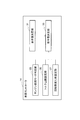
- FIG. 1 is a block diagram showing the configuration of a hybrid car including an electrically powered device according to an embodiment of the present invention.
- FIG. 2 is a block diagram showing functional components of the vehicle controller.
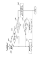
- FIG. 3 is a flowchart showing a processing procedure of torque limitation by the electrically powered device according to the embodiment of the present invention.
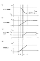
- FIG. 4 is a timing chart showing a first example of torque limitation by the electrically powered device according to one embodiment of the present invention, wherein (a) is a change in engine rotational speed, (b) is a change in accelerator opening, c) shows the change of the engine command torque, and (d) shows the change of the vehicle driving force.
- FIG. 1 is a block diagram showing the configuration of a hybrid car including an electrically powered device according to an embodiment of the present invention.
- FIG. 2 is a block diagram showing functional components of the vehicle controller.
- FIG. 3 is a flowchart showing a processing procedure of torque limitation by the electrically powered device according to the embodiment of the present invention.
- FIG. 5 is a timing chart showing a second example of torque limitation by the electrically-powered device according to the embodiment of the present invention, wherein (a) is a change in engine command torque, (b) is a change in vehicle driving force, c) shows the change of added power.
- the configuration of a hybrid car including the motor-driven device according to the present embodiment will be described with reference to FIG.
- the hybrid car of the present embodiment includes an engine 1 (internal combustion engine), a generator 4 (first motor), a battery 5, a drive motor 6 (second motor), and wheels 7 (drive wheels).
- the drive motor 6 drives the wheels 7 with the power from the battery 5 without driving the wheels 7 with the engine 1, and the engine 1, battery 5, drive motor 6 and wheels 7 are connected in series (series connection Because it is), it is called a series hybrid car.
- the engine 1 is mechanically coupled to the generator 4.
- the generator 4 is connected to the battery 5 so as to be capable of transmitting and receiving power. Power transmission and reception are also connected between the generator 4 and the drive motor 6, and between the battery 5 and the drive motor 6.
- the drive motor 6 is mechanically coupled to the axle via gears 16 and the axle is mechanically coupled to the wheel 7.
- the driving force of the engine 1 is transmitted to the generator 4, and the generator 4 is rotated by the driving force of the engine 1 to generate electric power.
- the power generated by the generator 4 flows to the battery 5
- the power is consumed to charge the battery 5.
- the power generated by the generator 4 flows to the drive motor 6, the power is consumed to drive the drive motor 6.
- the drive motor 6 receives supply of power from either or both of the generator 4 and the battery 5 and consumes the supplied power to generate drive power.
- the driving force of the drive motor 6 is transmitted to the wheel 7 via the gear 16 and the axle.
- the wheels 7 are rotated by the driving force of the drive motor 6, whereby the series hybrid car (hereinafter referred to as a vehicle) travels.
- the drive motor 6 operates as a generator to generate regenerative electric power.
- a regenerative braking force is generated on the wheel 7 via the gear 16 and the axle by the reaction of the torque input to the drive motor 6.
- the regenerative power generated by the drive motor 6 flows to the battery 5, the regenerative power is consumed to charge the battery 5. Further, when the regenerative electric power generated by the drive motor 6 flows to the generator 4, the regenerative electric power is consumed to drive the engine 1 and the generator 4 against the resistance (engine brake) of the engine 1 .
- the battery 5 has a function of charging and discharging. When the battery 5 is charged, the battery 5 stores energy of the power supplied from the generator 4 or the drive motor 6. When the battery 5 discharges, the battery 5 supplies the stored energy as electric power to the drive motor 6.
- the flow of power between the generator 4, the battery 5, and the drive motor 6 is determined by the state of the battery 5 and the drive motor 6, the traveling scene of the vehicle, and other accessories mounted on the vehicle (air conditioner, car stereo, etc. It may change based on the supply and demand condition of the electric power of the whole vehicle including a navigation system etc.).
- the flow of electric power between the generator 4, the battery 5, and the drive motor 6 is determined by the control of the vehicle controller 14 described later.
- the drive motor 6 when the drive motor 6 needs to generate a drive force, power may be supplied from the battery 5 to the drive motor 6.
- the engine 1 is driven to generate power by the generator 4, and in addition to the power from the battery 5, the power from the generator 4 is the drive motor 6 It may be supplied to
- the regenerative electric power generated by the drive motor 6 is supplied from the drive motor 6 to the battery 5 at the time of deceleration of the vehicle or when the vehicle goes down the slope. May be Furthermore, in a state where charging of the battery 5 is not completed, the engine 1 may be driven to generate electric power by the generator 4, and the electric power from the generator 4 may be supplied to the battery 5. .
- the vehicle selects a plurality of travel modes alternatively, a mode switch 17 (mode SW), a select lever 18 operated by a driver, a brake sensor 19 for detecting a braking force, and an accelerator position for detecting an accelerator opening. It further comprises a sensor 20 (APS), an engine state sensor 21 for detecting the state of the engine, and a vehicle controller 14 for controlling the entire hybrid car.
- the vehicle controller 14 functions as a control circuit that controls the electrically powered device according to the embodiment.
- the vehicle controller 14 is electrically connected to each of the mode switch 17, the select lever 18, the brake sensor 19, the accelerator position sensor 20, and the engine state sensor 21.
- the vehicle controller 14 receives a signal indicating the selected travel mode from the mode switch 17, receives a signal indicating the selected range from the select lever 18, and receives a signal indicating the brake hydraulic pressure from the brake sensor 19.
- a signal indicating the accelerator opening Ac of the accelerator pedal (input device) is received from the accelerator position sensor 20.
- the vehicle controller 14 also receives a signal indicating the state of the engine 1 from the engine state sensor 21.
- the signal indicating the state of the engine 1 includes a signal indicating whether the fuel is supplied to the engine 1 and a signal indicating the engine speed Nr.
- the range selectable by the select lever 18 includes, for example, a drive range (D), a brake range (B), a reverse range (R), a neutral range (N), a parking range (P) and the like.
- the vehicle controller 14 is electrically connected to the engine 1, the generator 4, and the drive motor 6 through a signal line.
- the vehicle controller 14 controls the engine 1, the generator 4, and the drive motor 6 in order to generate the required torque Tm (vehicle drive force FD) corresponding to the accelerator opening Ac by the drive motor 6.
- Tm vehicle drive force FD
- the vehicle controller 14 transmits the command torque Tc to the engine 1.
- the expression “transmit command torque Tc” includes controlling the engine 1 such that the torque output from the engine 1 becomes the command torque Tc. For example, by changing the throttle opening of the engine 1, changing the air fuel ratio, or changing the amount of fuel supplied to the engine 1, the torque output from the engine 1 becomes the command torque Tc. Including controlling the engine 1;
- the vehicle controller 14 controls the driving states of the engine 1, the generator 4 and the drive motor 6, and the state of the auxiliary equipment (not shown) is determined in addition to the power of the generator 4, the battery 5 and the drive motor 6. The flow is settled.
- the vehicle controller 14 can be realized by, for example, a general-purpose microcomputer including a CPU (central processing unit), a memory, and an input / output unit.
- a computer program (control program) for causing the microcomputer to function as the vehicle controller 14 is installed in the microcomputer and executed.
- the general-purpose microcomputer functions as the vehicle controller 14.
- the vehicle controller 14 may be configured by preparing dedicated hardware for executing each information processing described below. It is possible.
- the plurality of units (23, 25, 27, 31, 33) included in the vehicle controller 14 may be configured by individual hardware.
- the vehicle controller 14 may be shared with an electronic control unit (ECU) used for other control related to the vehicle.
- ECU electronice control unit
- the functional components of the vehicle controller 14 will be described with reference to FIG.
- the vehicle controller 14 includes, as functional components, an engine combustion mode determination unit 23, a torque upper limit setting unit 25, a rotation speed change rate setting unit 27, a request value determination unit 31, and a command value determination unit 33. Equipped with
- the engine combustion mode determination unit 23 receives a signal indicating the state of the engine 1 (a signal indicating whether the fuel is supplied to the engine 1 and a signal indicating the engine speed Nr) received from the engine state sensor 21. Based on this, the engine mode of the engine 1 is determined. There are two types of engine modes that the engine 1 can take, “non-combustion mode” and “combustion mode”.
- the “non-combustion mode” is a mode in which fuel and air are not supplied to the engine 1.
- the “combustion mode” is a mode in which fuel and air are supplied to the engine 1 and the engine speed Nr is in a predetermined speed range.
- the predetermined rotation range of the “combustion mode” is a rotation range which is determined in consideration of the characteristics at the time of firing of the engine 1. For example, the range of the engine speed Nr with which the fuel efficiency of the engine 1 is good is defined as the predetermined speed range.
- the required value determination unit 31 determines the required torque Tm to be generated by the drive motor 6 based on the accelerator opening Ac received from the accelerator position sensor 20.
- the required value determination unit 31 also generates a required power for the generator 4 by subtracting the power Pb that can be supplied from the battery 5 to the drive motor 6 from the power required to generate the required torque Tm by the drive motor 6. Determined as Pd.
- the required electric power Pd is determined as zero. Therefore, the required power Pd for the generator 4 has a value of 0 or more.
- the required value determining unit 31 determines a torque necessary for causing the generator 4 to generate the required power Pd as a required torque Ttg (predetermined torque threshold) for the engine 1.
- required value determination unit 31 subtracts the power obtained by subtracting the power that can be supplied from the battery 5 to the auxiliary equipment from the power required for charging the battery 5 and driving the auxiliary equipment (not shown) mounted on the vehicle. , Determined as auxiliary machine shortage power Pw. However, if the power that can be supplied from the battery 5 to the accessory is larger than the power required by the accessory mounted on the vehicle, the accessory shortage power Pw is determined to be zero. Therefore, the accessory shortage power Pw has a value of 0 or more. But
- the required value determination unit 31 determines a torque necessary for causing the generator 4 to generate the total power of the required power Pd and the auxiliary power shortage Pw as the required torque Tap for the engine 1.
- the required value determination unit 31 determines the target rotation speed Ntg of the engine 1 in the “combustion mode”.
- the target rotation speed Ntg is a value included in a predetermined rotation range of the “combustion mode”.
- the torque upper limit setting unit 25 sets a command torque for the engine 1 based on the engine mode determined by the engine combustion mode determination unit 23, the engine speed Nr received from the engine state sensor 21, and the target speed Ntg of the engine 1.
- a torque limit value Tmax (normal value Tn, limit value Tcr) which is an upper limit value of Tc is set.
- the normal value Tn is a limit value provided for safe driving of the engine 1 in consideration of a safety factor or the like.
- the limit value Tcr is a value smaller than the normal value Tn.
- the engine speed change rate setting unit 27 determines the engine speed based on the engine mode determined by the engine combustion mode determination unit 23, the engine speed Nr received from the engine state sensor 21, and the target speed Ntg of the engine 1.
- the rotation speed decrease rate Rdown (normal value Rn, limit value Rcr) of Nr is set.
- the limit value Rcr set to the rotation speed decrease rate Rdown is a value different from the normal value Rn. If necessary, the limit value Rcr may be larger than the normal value Rn, and the limit value Rcr may be smaller than the normal value Rn.
- the command value determination unit 33 compares the torque limit value Tmax set by the torque upper limit setting unit 25 with the required torque Tap determined by the required value determination unit 31, and gives a smaller value to the engine 1. Determined as torque Tc. Therefore, command torque Tc is set as a value that does not exceed torque limit value Tmax.
- the command value determination unit 33 determines whether the engine speed Nr received from the engine state sensor 21, the target rotation speed Ntg determined by the required value determination unit 31, and the rotation speed decrease set by the rotation speed change rate setting unit 27
- the commanded rotational speed Nc for the engine 1 is determined based on the rate Rdown. Specifically, in a situation where the engine speed Nr is decreased toward the target speed Ntg, the magnitude of the speed decrease per unit time of the engine speed Nr is equal to the speed decrease rate Rdown.
- the commanded rotational speed Nc is determined.
- the vehicle controller 14 controls the engine 1 based on the command torque Tc for the engine 1 and the command rotational speed Nc determined as described above.
- the process of torque limitation shown in FIG. 3 is started when the ignition of the vehicle is turned on, and is repeatedly executed until the ignition is turned off. Further, each time the torque limitation process shown in FIG. 3 is performed, the command value determination unit 33 determines the command torque Tc for the engine 1 and the command rotational speed Nc.
- step S101 the vehicle controller 14 determines whether the engine 1 is in combustion. More specifically, it is determined whether the engine mode of the engine 1 is "non-combustion mode" or "combustion mode". When the engine 1 is in the "combustion mode” (YES in step S101), the process proceeds to step S103. On the other hand, when the engine 1 is in the "non-combustion mode" (in the case of NO at step S101), the process proceeds to step S121.
- step S121 since torque limitation is not performed, a normal value Tn is set as the torque limit value Tmax, and a normal value Rn is set as the rotation speed decrease rate Rdown.
- step S103 the vehicle controller 14 determines whether or not the engine speed Nr is equal to or less than a value obtained by adding the predetermined value ⁇ Ne to the target speed Ntg.
- the predetermined value ⁇ Ne is a positive number. If “Nr ⁇ Ntg + ⁇ Ne” (YES in step S103), the process proceeds to step S121. If “Nr> Ntg + ⁇ Ne” (NO in step S103), the process proceeds to step S105.
- step S105 the vehicle controller 14 determines whether or not the engine rotational speed Nr is equal to or greater than the target rotational speed Ntg obtained by adding the predetermined value ⁇ Ns.
- the predetermined value ⁇ Ns is a positive number. If “Nr ⁇ Ntg + ⁇ Ns” (YES in step S105), the process proceeds to step S107. If “Nr ⁇ Ntg + ⁇ Ns” (NO in step S105), the process proceeds to step S111.
- step S107 in order to perform torque limitation, a limit value Tcr is set to the torque limit value Tmax, and a limit value Rcr is set to the rotation speed decrease rate Rdown.
- step S111 it is determined whether the required torque Ttg for the engine 1 is larger than the previous torque limit value Tmz.
- the previous torque limit value Tmz means the value of the previous torque limit value Tmax when the process of the torque limit shown in FIG. 3 is repeatedly performed. If “Ttg> Tmz” (YES in step S111), the process proceeds to step S113. If “Ttg ⁇ Tmz” (NO in step S111), the process proceeds to step S121.
- step S113 a predetermined value ⁇ Tcr is added to the previous torque limit value Tmz.
- the torque limit value Tmax is increased by a predetermined value ⁇ Tcr each time the process of the torque limit shown in FIG. 3 is repeatedly executed. That is, the torque limit value Tmax increases by a predetermined value ⁇ Tcr per unit step.
- step S111 and step S113 are not essential, and if NO in step S105, the process may proceed to step S121.
- FIGS. 4 (a) to 4 (d) show the timing charts of FIGS. 4 (a) to 4 (d).
- 4 (a) shows the change of the engine rotational speed Nr
- FIG. 4 (b) shows the change of the accelerator opening Ac
- FIG. 4 (c) shows the change of the command torque Tc to the engine 1
- FIG. 4 (d) shows the vehicle drive force.
- the situation of change of FD is shown.
- motoring control of the engine 1 is performed in a period before time t1, and the engine 1 is started at time t2, and in a period after time t2.
- the case where firing control is performed is shown.
- the vehicle driving force FD is a negative driving force (braking force).
- time t0 is a timing at which the accelerator opening Ac starts to increase from 0 by depressing the accelerator pedal.
- the fuel is supplied to the engine 1 and the timing at which the engine 1 starts driving is set to time t2. At time t2, the engine 1 switches from the "non-combustion mode" to the "combustion mode".
- auxiliary electric power shortage Pw is zero.
- the forced rotation of the regenerative power supplied from the drive motor 6 to the generator 4 is performed, so the engine speed Nr of the engine 1 is in the "combustion mode". This value is larger than the target rotation speed Ntg of.
- a period from time t1 to time t4 is a period during which the engine rotation speed Nr is reduced while transitioning from the motoring control state of the engine 1 to the firing control state.
- the engine rotation speed Nr of the engine 1 is reduced to a predetermined rotation range suitable for power generation by the torque of the generator 4 while power generation is performed by the generator 4.
- the vehicle driving force FD which is the braking force by the motoring control, starts to increase according to the accelerator opening Ac.
- the vehicle driving force FD becomes 0 at time t1
- the accelerator opening Ac when the vehicle driving force FD becomes 0 is called a neutral point, which corresponds to a state in which the driving motor 6 does not generate a positive driving force or a negative driving force.
- the limit value Tcr is set to the torque limit value Tmax, and the limit value Rcr is set to the rotation speed decrease rate Rdown.
- the command torque Tc is set in step S107 of FIG. 3 in the period from time t2 to time t3.
- the limit value is Tcr.
- the determination as to whether or not to perform torque limitation at the timing of driving the engine 1 is determined by the engine speed Nr and the magnitude of the target speed Ntg.
- torque limitation is performed I will not.
- command torque Tc is the limit value set in step S113 of FIG. 3 in the period from time t3 to time t4. It has become.
- the reason why the torque limit value Tmax is increased by the predetermined value ⁇ Tcr in the period from the time t3 to the time t4 is because the change in the driving force generated by the engine 1 is the amount of power generation by the generator 4 and This is because the vehicle driving force FD affects the feeling of acceleration felt by the vehicle occupant.
- the speed at which the torque limit value Tmax changes is limited by a predetermined value ⁇ Tcr.
- torque limit value Tmax has a normal value Tn
- Rn is set as the rotation speed decrease rate Rdown.
- FIGS. 5 (a) to 5 (c) show the change of the engine command torque
- FIG. 5 (b) shows the change of the vehicle driving force
- FIG. 5 (c) shows the change of the additional power.
- the timing charts of FIGS. 5 (a) to 5 (c) show the case where the auxiliary electric power shortage Pw is not zero.
- the change of the engine command torque shown in FIG. 5A is the same until the time t4, but the torque restriction is canceled at the time t4.
- the situation after the run is different. If the accessory shortage electric power Pw is not 0, the engine 1 is required to compensate for the electric power shortage in the accessories, so the required torque Tap having a command torque Tc to the engine 1 larger by ⁇ Tp than the required torque Ttg is required. Needs to be increased.
- the electric device control method and the electric device according to the present embodiment are connected to the engine 1 during a period in which the engine 1 (internal combustion engine) is transitioned from the "non-combustion mode" to the "combustion mode"
- the combustion mode in the predetermined speed range of the engine 1 Torque limitation is performed to lower the torque (command torque Tc) generated by the engine 1 than the required torque Ttg.
- the engine torque of the engine 1 in the "combustion mode” increases to the required torque Ttg in the predetermined rotation range It is a period of That is, the torque limitation for reducing the torque (command torque Tc) generated by the engine 1 lower than the required torque Ttg during the transition period limits the engine torque being increased, and does not decrease the engine torque.
- the torque limitation during the transition period is not accompanied by the reduction of the engine torque, the change of the driving force is small, so that the noise from the intake system of the engine 1 can be reduced without a sense of discomfort.
- the number of rotations of the engine 1 at the time of performing torque limitation than the number of rotations decrease rate Rdown (rotational speed reduction speed)
- the lowering rate Rdown may be increased.
- abnormal noise from the intake system of the engine 1 can be reduced, and the discomfort felt by the vehicle occupant can be reduced.
- the number of rotations of the engine 1 at the time of performing torque limitation than the number of rotations decrease rate Rdown (rotational speed reduction speed)
- the lowering rate Rdown may be reduced.
- the engine speed Nr changes smoothly in the period in which the engine speed Nr is reduced to the speed in the predetermined speed range, so that the volume of abnormal noise from the intake system of the engine 1 can be reduced.
- abnormal noise from the intake system of the engine 1 can be reduced, and the discomfort felt by the vehicle occupant can be reduced.
- the electric device control method and the electric device cancels the torque limitation when the difference between the engine rotational speed Nr and the target rotational speed Ntg falls below the predetermined value ⁇ Ne, and generates the torque generated by the engine 1
- the torque required for the engine 1 may be increased.
- the engine 1 after releasing the torque limitation, the engine 1 generates the torque until the torque generated by the engine 1 increases to the required torque Ttg (predetermined torque threshold).
- the speed of increase of the torque may be limited so as not to exceed a predetermined value ⁇ Tcr (predetermined limit value).
- ⁇ Tcr predetermined limit value
- the torque generated by the engine 1 for causing the generator 4 to generate the required power Pd necessary for driving the vehicle is set as the predetermined torque threshold. It may be one.
- the required power Pd required for driving the vehicle the power required for the drive motor 6 (second electric motor) to generate the torque required for driving the vehicle can be derived from the battery mounted on the vehicle The power obtained by subtracting the suppliable power Pb may be set. With these settings, the period for preventing the torque generated by the engine 1 from rapidly increasing after releasing the torque limitation is limited to the period for the power generated by the generator 4 to increase to the required power Pd. it can.
- Machine 4 supplies auxiliary machine insufficient power Pw (electric power obtained by subtracting the electric power that can be supplied to the auxiliary machine from the battery 5 from the electric power necessary for charging the battery 5 and driving the auxiliary machine mounted on the vehicle) Can.
- Pw electric power obtained by subtracting the electric power that can be supplied to the auxiliary machine from the battery 5 from the electric power necessary for charging the battery 5 and driving the auxiliary machine mounted on the vehicle
- the motor-driven device control method and the motor-driven device may implement torque limitation when the vehicle makes a transition from deceleration to acceleration.
- the transition from the motoring control performed at the time of deceleration of the vehicle to the firing control at the time of acceleration changes the engine 1 from the “non-combustion mode” to the “combustion mode”. It becomes possible to control.
- the processing circuitry comprises a programmed processing device, such as a processing device that includes an electrical circuit.
- the processing device also includes devices such as application specific integrated circuits (ASICs) and conventional circuit components arranged to perform the functions described in the embodiments.
- ASICs application specific integrated circuits
Abstract
Description
図1を参照して、本実施形態に係る電動装置を含むハイブリッドカーの構成を説明する。本実施形態のハイブリッドカーは、エンジン1(内燃機関)と、発電機4(第1電動機)と、バッテリ5と、駆動モータ6(第2電動機)と、車輪7(駆動輪)と、を備える。ハイブリッドカーは、エンジン1で車輪7を駆動せず、バッテリ5からの電力で駆動モータ6が車輪7を駆動するもので、エンジン1、バッテリ5、駆動モータ6、車輪7が直列接続(シリーズ接続)されることから、シリーズハイブリッドカーと称される。
次に、本実施形態に係る電動装置によるトルク制限の処理手順を、図3のフローチャートを参照して説明する。
次に、本実施形態に係る電動装置によるトルク制限の第1の例を、図4(a)~(d)のタイミングチャートを参照して説明する。図4(a)はエンジン回転数Nrの変化、図4(b)はアクセル開度Acの変化、図4(c)はエンジン1に対する指令トルクTcの変化、図4(d)は車両駆動力FDの変化の様子を示す。
次に、本実施形態に係る電動装置によるトルク制限の第2の例を、図5(a)~(c)のタイミングチャートを参照して説明する。図5(a)はエンジン指令トルクの変化、図5(b)は車両駆動力の変化、図5(c)は追加電力の変化の様子を示す。
以上詳細に説明したように、本実施形態に係る電動装置制御方法及び電動装置は、エンジン1(内燃機関)が「非燃焼モード」から「燃焼モード」に遷移させる期間中、エンジン1に接続された発電機4(第1電動機)によってエンジン1のエンジン回転数Nrを所定回転域の回転数にある目標回転数Ntgにまで低下させる期間において、「燃焼モード」のエンジン1の所定回転域での要求トルクTtgよりも、エンジン1が発生させるトルク(指令トルクTc)を低くするトルク制限を行う。これにより、モータリング制御からファイアリング制御に遷移しモータのトルクによって所定回転数域にまで低下させた際に生じるエンジン1の吸気系からの異音を低減することができる。また異音の低減により、車両の乗員が感じる違和感を低減することができる。
4 発電機
5 バッテリ
6 駆動モータ
7 車輪
14 車両コントローラ
16 ギア
17 モードスイッチ
18 セレクトレバー
19 ブレーキセンサ
20 アクセルポジションセンサ
21 エンジン状態センサ
23 エンジン燃焼モード判定部
25 トルク上限設定部
27 回転数変化率設定部
31 要求値決定部
33 指令値決定部
Claims (9)
- 内燃機関と、前記内燃機関に接続された第1電動機と、を備えた電動装置において、
前記内燃機関を非燃焼モードから燃焼モードに遷移させ、前記第1電動機によって前記内燃機関の回転数を所定回転域の回転数まで低下させる期間において、
前記燃焼モードの前記内燃機関に対する前記所定回転域での要求トルクよりも、前記内燃機関が発生させるトルクを低くするトルク制限を実施する電動装置制御方法。 - 請求項1に記載の電動装置制御方法であって、
前記燃焼モードの前記内燃機関の回転数低下速度よりも、前記トルク制限を実施する際の前記内燃機関の回転数低下速度を大きくすること
を特徴とする電動装置制御方法。 - 請求項1に記載の電動装置制御方法であって、
前記燃焼モードの前記内燃機関の回転数低下速度よりも、前記トルク制限を実施する際の前記内燃機関の回転数低下速度を小さくすること
を特徴とする電動装置制御方法。 - 請求項1~3のいずれか一項に記載の電動装置制御方法であって、
前記内燃機関の回転数と前記所定回転域にある目標回転数の差が所定値を下回った場合に、前記トルク制限を解除し、前記内燃機関が発生させるトルクを前記要求トルクまで増加させること
を特徴とする電動装置制御方法。 - 請求項4に記載の電動装置制御方法であって、
前記トルク制限を解除した後、前記内燃機関が発生させるトルクが所定トルク閾値まで増加するまでの間、前記内燃機関が発生させるトルクの増加速度が所定制限値を超えないように制限すること
を特徴とする電動装置制御方法。 - 請求項5に記載の電動装置制御方法であって、
前記所定トルク閾値は、前記電動装置が搭載された車両の駆動のために必要な要求電力を前記第1電動機で発生させるために前記内燃機関が発生させるトルクであること
を特徴とする電動装置制御方法。 - 請求項6に記載の電動装置制御方法であって、
前記要求電力は、前記車両を駆動するために必要なトルクを第2電動機で発生させるために必要な電力から、前記車両に搭載されたバッテリから供給可能な電力を差し引いた電力であること
を特徴とする電動装置制御方法。 - 請求項1~7のいずれか一項に記載の電動装置制御方法であって、
前記電動装置が搭載された車両が減速から加速に遷移する場合に、前記トルク制限を実施すること
を特徴とする電動装置制御方法。 - 内燃機関と、前記内燃機関に接続された第1電動機と、を備えた電動装置であって、
前記内燃機関を非燃焼モードから燃焼モードに遷移させ、前記第1電動機によって前記内燃機関の回転数を所定回転域の回転数まで低下させる期間において、
前記燃焼モードの前記内燃機関に対する前記所定回転域での要求トルクよりも、前記内燃機関が発生させるトルクを低くするトルク制限を実行する制御回路を備える電動装置。
Priority Applications (9)
| Application Number | Priority Date | Filing Date | Title |
|---|---|---|---|
| PCT/JP2017/045176 WO2019116559A1 (ja) | 2017-12-15 | 2017-12-15 | 電動装置制御方法及び電動装置 |
| EP17934615.0A EP3725623B1 (en) | 2017-12-15 | 2017-12-15 | Electric device control method and electric device |
| BR112020011808-7A BR112020011808A2 (pt) | 2017-12-15 | 2017-12-15 | método de controle de dispositivo elétrico e dispositivo elétrico |
| RU2020123238A RU2748924C1 (ru) | 2017-12-15 | 2017-12-15 | Способ управления силовой установкой и силовая установка |
| JP2019558849A JP6879383B2 (ja) | 2017-12-15 | 2017-12-15 | 電動装置制御方法及び電動装置 |
| KR1020207017091A KR102270995B1 (ko) | 2017-12-15 | 2017-12-15 | 전동 장치 제어 방법 및 전동 장치 |
| CN201780097725.9A CN111479740B (zh) | 2017-12-15 | 2017-12-15 | 电动装置控制方法和电动装置 |
| US16/771,143 US11312362B2 (en) | 2017-12-15 | 2017-12-15 | Electric device control method and electric device |
| MX2020006154A MX2020006154A (es) | 2017-12-15 | 2017-12-15 | Metodo de control de dispositivo electrico y dispositivo electrico. |
Applications Claiming Priority (1)
| Application Number | Priority Date | Filing Date | Title |
|---|---|---|---|
| PCT/JP2017/045176 WO2019116559A1 (ja) | 2017-12-15 | 2017-12-15 | 電動装置制御方法及び電動装置 |
Publications (1)
| Publication Number | Publication Date |
|---|---|
| WO2019116559A1 true WO2019116559A1 (ja) | 2019-06-20 |
Family
ID=66819153
Family Applications (1)
| Application Number | Title | Priority Date | Filing Date |
|---|---|---|---|
| PCT/JP2017/045176 WO2019116559A1 (ja) | 2017-12-15 | 2017-12-15 | 電動装置制御方法及び電動装置 |
Country Status (9)
| Country | Link |
|---|---|
| US (1) | US11312362B2 (ja) |
| EP (1) | EP3725623B1 (ja) |
| JP (1) | JP6879383B2 (ja) |
| KR (1) | KR102270995B1 (ja) |
| CN (1) | CN111479740B (ja) |
| BR (1) | BR112020011808A2 (ja) |
| MX (1) | MX2020006154A (ja) |
| RU (1) | RU2748924C1 (ja) |
| WO (1) | WO2019116559A1 (ja) |
Citations (4)
| Publication number | Priority date | Publication date | Assignee | Title |
|---|---|---|---|---|
| JP2004242450A (ja) * | 2003-02-07 | 2004-08-26 | Nissan Motor Co Ltd | ハイブリッド車両の制御装置 |
| JP2004248472A (ja) * | 2003-02-17 | 2004-09-02 | Nissan Motor Co Ltd | ハイブリッド車両の制御装置 |
| JP2015093597A (ja) * | 2013-11-13 | 2015-05-18 | マツダ株式会社 | ハイブリッド車の制御装置 |
| JP2017114206A (ja) | 2015-12-22 | 2017-06-29 | 三菱自動車工業株式会社 | 回生制御装置 |
Family Cites Families (13)
| Publication number | Priority date | Publication date | Assignee | Title |
|---|---|---|---|---|
| JP2006132465A (ja) * | 2004-11-08 | 2006-05-25 | Toyota Motor Corp | ハイブリッド車およびその制御方法 |
| US8112208B2 (en) * | 2009-05-28 | 2012-02-07 | Ford Global Technologies, Llc | Engine speed reduction preparatory to an engine restart |
| US8626424B2 (en) * | 2009-08-05 | 2014-01-07 | GM Global Technology Operations LLC | Active coast and cruise control system and methods |
| CN103534156B (zh) * | 2011-06-30 | 2016-08-31 | 日产自动车株式会社 | 混合动力车辆的控制装置 |
| JP2013071603A (ja) * | 2011-09-28 | 2013-04-22 | Toyota Motor Corp | ハイブリッド車両の制御装置 |
| JP2013107524A (ja) * | 2011-11-22 | 2013-06-06 | Toyota Motor Corp | 動力出力装置 |
| US9670865B2 (en) * | 2012-03-16 | 2017-06-06 | Nissan Motor Co., Ltd. | Driving control device and driving control method in hybrid electric vehicle |
| CN104411555B (zh) * | 2012-07-05 | 2017-04-12 | 丰田自动车株式会社 | 混合动力车辆的控制装置 |
| JP5974796B2 (ja) * | 2012-10-05 | 2016-08-23 | トヨタ自動車株式会社 | ハイブリッド車両およびハイブリッド車両の制御方法 |
| CN104918834B (zh) * | 2013-01-24 | 2017-07-07 | 丰田自动车株式会社 | 混合动力车辆的控制装置 |
| US9527497B2 (en) * | 2013-05-31 | 2016-12-27 | Toyota Jidosha Kabushiki Kaisha | Control device for hybrid vehicle |
| JP6500368B2 (ja) * | 2014-08-27 | 2019-04-17 | 三菱自動車工業株式会社 | ハイブリッド車両の回生制御装置 |
| JP6617732B2 (ja) * | 2017-02-17 | 2019-12-11 | トヨタ自動車株式会社 | 車両の変速制御装置 |
-
2017
- 2017-12-15 MX MX2020006154A patent/MX2020006154A/es unknown
- 2017-12-15 RU RU2020123238A patent/RU2748924C1/ru active
- 2017-12-15 CN CN201780097725.9A patent/CN111479740B/zh active Active
- 2017-12-15 BR BR112020011808-7A patent/BR112020011808A2/pt active Search and Examination
- 2017-12-15 US US16/771,143 patent/US11312362B2/en active Active
- 2017-12-15 WO PCT/JP2017/045176 patent/WO2019116559A1/ja unknown
- 2017-12-15 JP JP2019558849A patent/JP6879383B2/ja active Active
- 2017-12-15 KR KR1020207017091A patent/KR102270995B1/ko active IP Right Grant
- 2017-12-15 EP EP17934615.0A patent/EP3725623B1/en active Active
Patent Citations (4)
| Publication number | Priority date | Publication date | Assignee | Title |
|---|---|---|---|---|
| JP2004242450A (ja) * | 2003-02-07 | 2004-08-26 | Nissan Motor Co Ltd | ハイブリッド車両の制御装置 |
| JP2004248472A (ja) * | 2003-02-17 | 2004-09-02 | Nissan Motor Co Ltd | ハイブリッド車両の制御装置 |
| JP2015093597A (ja) * | 2013-11-13 | 2015-05-18 | マツダ株式会社 | ハイブリッド車の制御装置 |
| JP2017114206A (ja) | 2015-12-22 | 2017-06-29 | 三菱自動車工業株式会社 | 回生制御装置 |
Non-Patent Citations (1)
| Title |
|---|
| See also references of EP3725623A4 |
Also Published As
| Publication number | Publication date |
|---|---|
| RU2748924C1 (ru) | 2021-06-01 |
| KR102270995B1 (ko) | 2021-07-02 |
| CN111479740A (zh) | 2020-07-31 |
| BR112020011808A2 (pt) | 2020-11-17 |
| JPWO2019116559A1 (ja) | 2021-01-14 |
| MX2020006154A (es) | 2020-08-13 |
| EP3725623A4 (en) | 2020-12-16 |
| JP6879383B2 (ja) | 2021-06-02 |
| EP3725623A1 (en) | 2020-10-21 |
| CN111479740B (zh) | 2023-02-28 |
| US11312362B2 (en) | 2022-04-26 |
| KR20200086715A (ko) | 2020-07-17 |
| EP3725623B1 (en) | 2024-03-13 |
| US20210162981A1 (en) | 2021-06-03 |
Similar Documents
| Publication | Publication Date | Title |
|---|---|---|
| US8040084B2 (en) | Vehicle, control method thereof and braking device | |
| US7270621B2 (en) | Moving body and control method of moving body | |
| WO2019116586A1 (ja) | ハイブリッド車両の制御方法、及び、制御装置 | |
| JP5200797B2 (ja) | ハイブリッド自動車の制御方法及びその装置 | |
| JP2009504469A (ja) | 自動車用ドライブトレイン及びドライブトレインの運転方法 | |
| JP2008150022A (ja) | Etcが搭載されたハイブリッド電気自動車のエンジントルク制御方法 | |
| JP2010201987A (ja) | ハイブリッド車両の駆動制御装置 | |
| JP5360297B2 (ja) | 車両用制御装置および車両用制御方法 | |
| JP2008168720A (ja) | 自動車およびその制御方法 | |
| WO2019116576A1 (ja) | ハイブリッド車両の制御方法、及び、制御装置 | |
| JP5092611B2 (ja) | 車両の駆動力制御装置 | |
| WO2019116553A1 (ja) | 回生ブレーキ制御方法及び回生ブレーキ制御装置 | |
| JP3999786B2 (ja) | 駆動装置およびこれを搭載する車両並びに動力出力装置,駆動装置の制御方法 | |
| JP2011097666A (ja) | 自動車およびその制御方法 | |
| JP2011068211A (ja) | ハイブリッド車両およびその制御方法 | |
| JP4285483B2 (ja) | 車両およびその制御方法 | |
| WO2019116559A1 (ja) | 電動装置制御方法及び電動装置 | |
| JP5741068B2 (ja) | 電動車両 | |
| WO2012137297A1 (ja) | 車両および車両用制御方法 | |
| JP7433698B2 (ja) | モータ制御装置 | |
| WO2019188362A1 (ja) | ハイブリッド車両の発電制御装置 | |
| JP2012046106A (ja) | ハイブリッド自動車 | |
| JP2004229354A (ja) | ハイブリッド車両の制御装置 | |
| WO2010073328A1 (ja) | 車両制御装置 | |
| JPWO2014087474A1 (ja) | 車両の制御システム |
Legal Events
| Date | Code | Title | Description |
|---|---|---|---|
| 121 | Ep: the epo has been informed by wipo that ep was designated in this application |
Ref document number: 17934615 Country of ref document: EP Kind code of ref document: A1 |
|
| ENP | Entry into the national phase |
Ref document number: 2019558849 Country of ref document: JP Kind code of ref document: A |
|
| ENP | Entry into the national phase |
Ref document number: 20207017091 Country of ref document: KR Kind code of ref document: A |
|
| NENP | Non-entry into the national phase |
Ref country code: DE |
|
| ENP | Entry into the national phase |
Ref document number: 2017934615 Country of ref document: EP Effective date: 20200715 |
|
| REG | Reference to national code |
Ref country code: BR Ref legal event code: B01A Ref document number: 112020011808 Country of ref document: BR |
|
| ENP | Entry into the national phase |
Ref document number: 112020011808 Country of ref document: BR Kind code of ref document: A2 Effective date: 20200612 |