EP3725623B1 - Electric device control method and electric device - Google Patents
Electric device control method and electric device Download PDFInfo
- Publication number
- EP3725623B1 EP3725623B1 EP17934615.0A EP17934615A EP3725623B1 EP 3725623 B1 EP3725623 B1 EP 3725623B1 EP 17934615 A EP17934615 A EP 17934615A EP 3725623 B1 EP3725623 B1 EP 3725623B1
- Authority
- EP
- European Patent Office
- Prior art keywords
- torque
- engine
- internal combustion
- combustion engine
- power
- Prior art date
- Legal status (The legal status is an assumption and is not a legal conclusion. Google has not performed a legal analysis and makes no representation as to the accuracy of the status listed.)
- Active
Links
- 238000000034 method Methods 0.000 title claims description 33
- 238000002485 combustion reaction Methods 0.000 claims description 67
- 230000003247 decreasing effect Effects 0.000 claims description 13
- 230000001133 acceleration Effects 0.000 claims description 8
- 230000001172 regenerating effect Effects 0.000 description 26
- 230000008859 change Effects 0.000 description 24
- 238000010304 firing Methods 0.000 description 15
- 239000000446 fuel Substances 0.000 description 15
- 230000001788 irregular Effects 0.000 description 14
- 230000008569 process Effects 0.000 description 12
- 230000006870 function Effects 0.000 description 6
- 230000007704 transition Effects 0.000 description 6
- 238000010248 power generation Methods 0.000 description 4
- 239000000470 constituent Substances 0.000 description 3
- 230000007935 neutral effect Effects 0.000 description 3
- 238000004590 computer program Methods 0.000 description 2
- 238000010586 diagram Methods 0.000 description 2
- 230000000694 effects Effects 0.000 description 2
- 230000009467 reduction Effects 0.000 description 2
- 238000006243 chemical reaction Methods 0.000 description 1
- 230000001419 dependent effect Effects 0.000 description 1
- 230000010365 information processing Effects 0.000 description 1
- 230000007246 mechanism Effects 0.000 description 1
Images

Classifications
-
- B—PERFORMING OPERATIONS; TRANSPORTING
- B60—VEHICLES IN GENERAL
- B60W—CONJOINT CONTROL OF VEHICLE SUB-UNITS OF DIFFERENT TYPE OR DIFFERENT FUNCTION; CONTROL SYSTEMS SPECIALLY ADAPTED FOR HYBRID VEHICLES; ROAD VEHICLE DRIVE CONTROL SYSTEMS FOR PURPOSES NOT RELATED TO THE CONTROL OF A PARTICULAR SUB-UNIT
- B60W10/00—Conjoint control of vehicle sub-units of different type or different function
- B60W10/04—Conjoint control of vehicle sub-units of different type or different function including control of propulsion units
- B60W10/06—Conjoint control of vehicle sub-units of different type or different function including control of propulsion units including control of combustion engines
-
- B—PERFORMING OPERATIONS; TRANSPORTING
- B60—VEHICLES IN GENERAL
- B60W—CONJOINT CONTROL OF VEHICLE SUB-UNITS OF DIFFERENT TYPE OR DIFFERENT FUNCTION; CONTROL SYSTEMS SPECIALLY ADAPTED FOR HYBRID VEHICLES; ROAD VEHICLE DRIVE CONTROL SYSTEMS FOR PURPOSES NOT RELATED TO THE CONTROL OF A PARTICULAR SUB-UNIT
- B60W20/00—Control systems specially adapted for hybrid vehicles
- B60W20/10—Controlling the power contribution of each of the prime movers to meet required power demand
- B60W20/15—Control strategies specially adapted for achieving a particular effect
- B60W20/17—Control strategies specially adapted for achieving a particular effect for noise reduction
-
- B—PERFORMING OPERATIONS; TRANSPORTING
- B60—VEHICLES IN GENERAL
- B60K—ARRANGEMENT OR MOUNTING OF PROPULSION UNITS OR OF TRANSMISSIONS IN VEHICLES; ARRANGEMENT OR MOUNTING OF PLURAL DIVERSE PRIME-MOVERS IN VEHICLES; AUXILIARY DRIVES FOR VEHICLES; INSTRUMENTATION OR DASHBOARDS FOR VEHICLES; ARRANGEMENTS IN CONNECTION WITH COOLING, AIR INTAKE, GAS EXHAUST OR FUEL SUPPLY OF PROPULSION UNITS IN VEHICLES
- B60K1/00—Arrangement or mounting of electrical propulsion units
- B60K1/04—Arrangement or mounting of electrical propulsion units of the electric storage means for propulsion
-
- B—PERFORMING OPERATIONS; TRANSPORTING
- B60—VEHICLES IN GENERAL
- B60K—ARRANGEMENT OR MOUNTING OF PROPULSION UNITS OR OF TRANSMISSIONS IN VEHICLES; ARRANGEMENT OR MOUNTING OF PLURAL DIVERSE PRIME-MOVERS IN VEHICLES; AUXILIARY DRIVES FOR VEHICLES; INSTRUMENTATION OR DASHBOARDS FOR VEHICLES; ARRANGEMENTS IN CONNECTION WITH COOLING, AIR INTAKE, GAS EXHAUST OR FUEL SUPPLY OF PROPULSION UNITS IN VEHICLES
- B60K6/00—Arrangement or mounting of plural diverse prime-movers for mutual or common propulsion, e.g. hybrid propulsion systems comprising electric motors and internal combustion engines ; Control systems therefor, i.e. systems controlling two or more prime movers, or controlling one of these prime movers and any of the transmission, drive or drive units Informative references: mechanical gearings with secondary electric drive F16H3/72; arrangements for handling mechanical energy structurally associated with the dynamo-electric machine H02K7/00; machines comprising structurally interrelated motor and generator parts H02K51/00; dynamo-electric machines not otherwise provided for in H02K see H02K99/00
- B60K6/20—Arrangement or mounting of plural diverse prime-movers for mutual or common propulsion, e.g. hybrid propulsion systems comprising electric motors and internal combustion engines ; Control systems therefor, i.e. systems controlling two or more prime movers, or controlling one of these prime movers and any of the transmission, drive or drive units Informative references: mechanical gearings with secondary electric drive F16H3/72; arrangements for handling mechanical energy structurally associated with the dynamo-electric machine H02K7/00; machines comprising structurally interrelated motor and generator parts H02K51/00; dynamo-electric machines not otherwise provided for in H02K see H02K99/00 the prime-movers consisting of electric motors and internal combustion engines, e.g. HEVs
- B60K6/22—Arrangement or mounting of plural diverse prime-movers for mutual or common propulsion, e.g. hybrid propulsion systems comprising electric motors and internal combustion engines ; Control systems therefor, i.e. systems controlling two or more prime movers, or controlling one of these prime movers and any of the transmission, drive or drive units Informative references: mechanical gearings with secondary electric drive F16H3/72; arrangements for handling mechanical energy structurally associated with the dynamo-electric machine H02K7/00; machines comprising structurally interrelated motor and generator parts H02K51/00; dynamo-electric machines not otherwise provided for in H02K see H02K99/00 the prime-movers consisting of electric motors and internal combustion engines, e.g. HEVs characterised by apparatus, components or means specially adapted for HEVs
- B60K6/24—Arrangement or mounting of plural diverse prime-movers for mutual or common propulsion, e.g. hybrid propulsion systems comprising electric motors and internal combustion engines ; Control systems therefor, i.e. systems controlling two or more prime movers, or controlling one of these prime movers and any of the transmission, drive or drive units Informative references: mechanical gearings with secondary electric drive F16H3/72; arrangements for handling mechanical energy structurally associated with the dynamo-electric machine H02K7/00; machines comprising structurally interrelated motor and generator parts H02K51/00; dynamo-electric machines not otherwise provided for in H02K see H02K99/00 the prime-movers consisting of electric motors and internal combustion engines, e.g. HEVs characterised by apparatus, components or means specially adapted for HEVs characterised by the combustion engines
-
- B—PERFORMING OPERATIONS; TRANSPORTING
- B60—VEHICLES IN GENERAL
- B60K—ARRANGEMENT OR MOUNTING OF PROPULSION UNITS OR OF TRANSMISSIONS IN VEHICLES; ARRANGEMENT OR MOUNTING OF PLURAL DIVERSE PRIME-MOVERS IN VEHICLES; AUXILIARY DRIVES FOR VEHICLES; INSTRUMENTATION OR DASHBOARDS FOR VEHICLES; ARRANGEMENTS IN CONNECTION WITH COOLING, AIR INTAKE, GAS EXHAUST OR FUEL SUPPLY OF PROPULSION UNITS IN VEHICLES
- B60K6/00—Arrangement or mounting of plural diverse prime-movers for mutual or common propulsion, e.g. hybrid propulsion systems comprising electric motors and internal combustion engines ; Control systems therefor, i.e. systems controlling two or more prime movers, or controlling one of these prime movers and any of the transmission, drive or drive units Informative references: mechanical gearings with secondary electric drive F16H3/72; arrangements for handling mechanical energy structurally associated with the dynamo-electric machine H02K7/00; machines comprising structurally interrelated motor and generator parts H02K51/00; dynamo-electric machines not otherwise provided for in H02K see H02K99/00
- B60K6/20—Arrangement or mounting of plural diverse prime-movers for mutual or common propulsion, e.g. hybrid propulsion systems comprising electric motors and internal combustion engines ; Control systems therefor, i.e. systems controlling two or more prime movers, or controlling one of these prime movers and any of the transmission, drive or drive units Informative references: mechanical gearings with secondary electric drive F16H3/72; arrangements for handling mechanical energy structurally associated with the dynamo-electric machine H02K7/00; machines comprising structurally interrelated motor and generator parts H02K51/00; dynamo-electric machines not otherwise provided for in H02K see H02K99/00 the prime-movers consisting of electric motors and internal combustion engines, e.g. HEVs
- B60K6/22—Arrangement or mounting of plural diverse prime-movers for mutual or common propulsion, e.g. hybrid propulsion systems comprising electric motors and internal combustion engines ; Control systems therefor, i.e. systems controlling two or more prime movers, or controlling one of these prime movers and any of the transmission, drive or drive units Informative references: mechanical gearings with secondary electric drive F16H3/72; arrangements for handling mechanical energy structurally associated with the dynamo-electric machine H02K7/00; machines comprising structurally interrelated motor and generator parts H02K51/00; dynamo-electric machines not otherwise provided for in H02K see H02K99/00 the prime-movers consisting of electric motors and internal combustion engines, e.g. HEVs characterised by apparatus, components or means specially adapted for HEVs
- B60K6/26—Arrangement or mounting of plural diverse prime-movers for mutual or common propulsion, e.g. hybrid propulsion systems comprising electric motors and internal combustion engines ; Control systems therefor, i.e. systems controlling two or more prime movers, or controlling one of these prime movers and any of the transmission, drive or drive units Informative references: mechanical gearings with secondary electric drive F16H3/72; arrangements for handling mechanical energy structurally associated with the dynamo-electric machine H02K7/00; machines comprising structurally interrelated motor and generator parts H02K51/00; dynamo-electric machines not otherwise provided for in H02K see H02K99/00 the prime-movers consisting of electric motors and internal combustion engines, e.g. HEVs characterised by apparatus, components or means specially adapted for HEVs characterised by the motors or the generators
-
- B—PERFORMING OPERATIONS; TRANSPORTING
- B60—VEHICLES IN GENERAL
- B60K—ARRANGEMENT OR MOUNTING OF PROPULSION UNITS OR OF TRANSMISSIONS IN VEHICLES; ARRANGEMENT OR MOUNTING OF PLURAL DIVERSE PRIME-MOVERS IN VEHICLES; AUXILIARY DRIVES FOR VEHICLES; INSTRUMENTATION OR DASHBOARDS FOR VEHICLES; ARRANGEMENTS IN CONNECTION WITH COOLING, AIR INTAKE, GAS EXHAUST OR FUEL SUPPLY OF PROPULSION UNITS IN VEHICLES
- B60K6/00—Arrangement or mounting of plural diverse prime-movers for mutual or common propulsion, e.g. hybrid propulsion systems comprising electric motors and internal combustion engines ; Control systems therefor, i.e. systems controlling two or more prime movers, or controlling one of these prime movers and any of the transmission, drive or drive units Informative references: mechanical gearings with secondary electric drive F16H3/72; arrangements for handling mechanical energy structurally associated with the dynamo-electric machine H02K7/00; machines comprising structurally interrelated motor and generator parts H02K51/00; dynamo-electric machines not otherwise provided for in H02K see H02K99/00
- B60K6/20—Arrangement or mounting of plural diverse prime-movers for mutual or common propulsion, e.g. hybrid propulsion systems comprising electric motors and internal combustion engines ; Control systems therefor, i.e. systems controlling two or more prime movers, or controlling one of these prime movers and any of the transmission, drive or drive units Informative references: mechanical gearings with secondary electric drive F16H3/72; arrangements for handling mechanical energy structurally associated with the dynamo-electric machine H02K7/00; machines comprising structurally interrelated motor and generator parts H02K51/00; dynamo-electric machines not otherwise provided for in H02K see H02K99/00 the prime-movers consisting of electric motors and internal combustion engines, e.g. HEVs
- B60K6/42—Arrangement or mounting of plural diverse prime-movers for mutual or common propulsion, e.g. hybrid propulsion systems comprising electric motors and internal combustion engines ; Control systems therefor, i.e. systems controlling two or more prime movers, or controlling one of these prime movers and any of the transmission, drive or drive units Informative references: mechanical gearings with secondary electric drive F16H3/72; arrangements for handling mechanical energy structurally associated with the dynamo-electric machine H02K7/00; machines comprising structurally interrelated motor and generator parts H02K51/00; dynamo-electric machines not otherwise provided for in H02K see H02K99/00 the prime-movers consisting of electric motors and internal combustion engines, e.g. HEVs characterised by the architecture of the hybrid electric vehicle
- B60K6/46—Series type
-
- B—PERFORMING OPERATIONS; TRANSPORTING
- B60—VEHICLES IN GENERAL
- B60W—CONJOINT CONTROL OF VEHICLE SUB-UNITS OF DIFFERENT TYPE OR DIFFERENT FUNCTION; CONTROL SYSTEMS SPECIALLY ADAPTED FOR HYBRID VEHICLES; ROAD VEHICLE DRIVE CONTROL SYSTEMS FOR PURPOSES NOT RELATED TO THE CONTROL OF A PARTICULAR SUB-UNIT
- B60W10/00—Conjoint control of vehicle sub-units of different type or different function
- B60W10/04—Conjoint control of vehicle sub-units of different type or different function including control of propulsion units
- B60W10/08—Conjoint control of vehicle sub-units of different type or different function including control of propulsion units including control of electric propulsion units, e.g. motors or generators
-
- B—PERFORMING OPERATIONS; TRANSPORTING
- B60—VEHICLES IN GENERAL
- B60W—CONJOINT CONTROL OF VEHICLE SUB-UNITS OF DIFFERENT TYPE OR DIFFERENT FUNCTION; CONTROL SYSTEMS SPECIALLY ADAPTED FOR HYBRID VEHICLES; ROAD VEHICLE DRIVE CONTROL SYSTEMS FOR PURPOSES NOT RELATED TO THE CONTROL OF A PARTICULAR SUB-UNIT
- B60W10/00—Conjoint control of vehicle sub-units of different type or different function
- B60W10/24—Conjoint control of vehicle sub-units of different type or different function including control of energy storage means
-
- B—PERFORMING OPERATIONS; TRANSPORTING
- B60—VEHICLES IN GENERAL
- B60W—CONJOINT CONTROL OF VEHICLE SUB-UNITS OF DIFFERENT TYPE OR DIFFERENT FUNCTION; CONTROL SYSTEMS SPECIALLY ADAPTED FOR HYBRID VEHICLES; ROAD VEHICLE DRIVE CONTROL SYSTEMS FOR PURPOSES NOT RELATED TO THE CONTROL OF A PARTICULAR SUB-UNIT
- B60W20/00—Control systems specially adapted for hybrid vehicles
- B60W20/10—Controlling the power contribution of each of the prime movers to meet required power demand
- B60W20/13—Controlling the power contribution of each of the prime movers to meet required power demand in order to stay within battery power input or output limits; in order to prevent overcharging or battery depletion
- B60W20/14—Controlling the power contribution of each of the prime movers to meet required power demand in order to stay within battery power input or output limits; in order to prevent overcharging or battery depletion in conjunction with braking regeneration
-
- B—PERFORMING OPERATIONS; TRANSPORTING
- B60—VEHICLES IN GENERAL
- B60W—CONJOINT CONTROL OF VEHICLE SUB-UNITS OF DIFFERENT TYPE OR DIFFERENT FUNCTION; CONTROL SYSTEMS SPECIALLY ADAPTED FOR HYBRID VEHICLES; ROAD VEHICLE DRIVE CONTROL SYSTEMS FOR PURPOSES NOT RELATED TO THE CONTROL OF A PARTICULAR SUB-UNIT
- B60W20/00—Control systems specially adapted for hybrid vehicles
- B60W20/40—Controlling the engagement or disengagement of prime movers, e.g. for transition between prime movers
-
- B—PERFORMING OPERATIONS; TRANSPORTING
- B60—VEHICLES IN GENERAL
- B60W—CONJOINT CONTROL OF VEHICLE SUB-UNITS OF DIFFERENT TYPE OR DIFFERENT FUNCTION; CONTROL SYSTEMS SPECIALLY ADAPTED FOR HYBRID VEHICLES; ROAD VEHICLE DRIVE CONTROL SYSTEMS FOR PURPOSES NOT RELATED TO THE CONTROL OF A PARTICULAR SUB-UNIT
- B60W30/00—Purposes of road vehicle drive control systems not related to the control of a particular sub-unit, e.g. of systems using conjoint control of vehicle sub-units, or advanced driver assistance systems for ensuring comfort, stability and safety or drive control systems for propelling or retarding the vehicle
- B60W30/18—Propelling the vehicle
- B60W30/18009—Propelling the vehicle related to particular drive situations
- B60W30/18109—Braking
- B60W30/18127—Regenerative braking
-
- B—PERFORMING OPERATIONS; TRANSPORTING
- B60—VEHICLES IN GENERAL
- B60W—CONJOINT CONTROL OF VEHICLE SUB-UNITS OF DIFFERENT TYPE OR DIFFERENT FUNCTION; CONTROL SYSTEMS SPECIALLY ADAPTED FOR HYBRID VEHICLES; ROAD VEHICLE DRIVE CONTROL SYSTEMS FOR PURPOSES NOT RELATED TO THE CONTROL OF A PARTICULAR SUB-UNIT
- B60W30/00—Purposes of road vehicle drive control systems not related to the control of a particular sub-unit, e.g. of systems using conjoint control of vehicle sub-units, or advanced driver assistance systems for ensuring comfort, stability and safety or drive control systems for propelling or retarding the vehicle
- B60W30/18—Propelling the vehicle
- B60W30/192—Mitigating problems related to power-up or power-down of the driveline, e.g. start-up of a cold engine
-
- B—PERFORMING OPERATIONS; TRANSPORTING
- B60—VEHICLES IN GENERAL
- B60W—CONJOINT CONTROL OF VEHICLE SUB-UNITS OF DIFFERENT TYPE OR DIFFERENT FUNCTION; CONTROL SYSTEMS SPECIALLY ADAPTED FOR HYBRID VEHICLES; ROAD VEHICLE DRIVE CONTROL SYSTEMS FOR PURPOSES NOT RELATED TO THE CONTROL OF A PARTICULAR SUB-UNIT
- B60W60/00—Drive control systems specially adapted for autonomous road vehicles
-
- B—PERFORMING OPERATIONS; TRANSPORTING
- B60—VEHICLES IN GENERAL
- B60K—ARRANGEMENT OR MOUNTING OF PROPULSION UNITS OR OF TRANSMISSIONS IN VEHICLES; ARRANGEMENT OR MOUNTING OF PLURAL DIVERSE PRIME-MOVERS IN VEHICLES; AUXILIARY DRIVES FOR VEHICLES; INSTRUMENTATION OR DASHBOARDS FOR VEHICLES; ARRANGEMENTS IN CONNECTION WITH COOLING, AIR INTAKE, GAS EXHAUST OR FUEL SUPPLY OF PROPULSION UNITS IN VEHICLES
- B60K6/00—Arrangement or mounting of plural diverse prime-movers for mutual or common propulsion, e.g. hybrid propulsion systems comprising electric motors and internal combustion engines ; Control systems therefor, i.e. systems controlling two or more prime movers, or controlling one of these prime movers and any of the transmission, drive or drive units Informative references: mechanical gearings with secondary electric drive F16H3/72; arrangements for handling mechanical energy structurally associated with the dynamo-electric machine H02K7/00; machines comprising structurally interrelated motor and generator parts H02K51/00; dynamo-electric machines not otherwise provided for in H02K see H02K99/00
- B60K6/20—Arrangement or mounting of plural diverse prime-movers for mutual or common propulsion, e.g. hybrid propulsion systems comprising electric motors and internal combustion engines ; Control systems therefor, i.e. systems controlling two or more prime movers, or controlling one of these prime movers and any of the transmission, drive or drive units Informative references: mechanical gearings with secondary electric drive F16H3/72; arrangements for handling mechanical energy structurally associated with the dynamo-electric machine H02K7/00; machines comprising structurally interrelated motor and generator parts H02K51/00; dynamo-electric machines not otherwise provided for in H02K see H02K99/00 the prime-movers consisting of electric motors and internal combustion engines, e.g. HEVs
- B60K6/22—Arrangement or mounting of plural diverse prime-movers for mutual or common propulsion, e.g. hybrid propulsion systems comprising electric motors and internal combustion engines ; Control systems therefor, i.e. systems controlling two or more prime movers, or controlling one of these prime movers and any of the transmission, drive or drive units Informative references: mechanical gearings with secondary electric drive F16H3/72; arrangements for handling mechanical energy structurally associated with the dynamo-electric machine H02K7/00; machines comprising structurally interrelated motor and generator parts H02K51/00; dynamo-electric machines not otherwise provided for in H02K see H02K99/00 the prime-movers consisting of electric motors and internal combustion engines, e.g. HEVs characterised by apparatus, components or means specially adapted for HEVs
- B60K6/26—Arrangement or mounting of plural diverse prime-movers for mutual or common propulsion, e.g. hybrid propulsion systems comprising electric motors and internal combustion engines ; Control systems therefor, i.e. systems controlling two or more prime movers, or controlling one of these prime movers and any of the transmission, drive or drive units Informative references: mechanical gearings with secondary electric drive F16H3/72; arrangements for handling mechanical energy structurally associated with the dynamo-electric machine H02K7/00; machines comprising structurally interrelated motor and generator parts H02K51/00; dynamo-electric machines not otherwise provided for in H02K see H02K99/00 the prime-movers consisting of electric motors and internal combustion engines, e.g. HEVs characterised by apparatus, components or means specially adapted for HEVs characterised by the motors or the generators
- B60K2006/268—Electric drive motor starts the engine, i.e. used as starter motor
-
- B—PERFORMING OPERATIONS; TRANSPORTING
- B60—VEHICLES IN GENERAL
- B60W—CONJOINT CONTROL OF VEHICLE SUB-UNITS OF DIFFERENT TYPE OR DIFFERENT FUNCTION; CONTROL SYSTEMS SPECIALLY ADAPTED FOR HYBRID VEHICLES; ROAD VEHICLE DRIVE CONTROL SYSTEMS FOR PURPOSES NOT RELATED TO THE CONTROL OF A PARTICULAR SUB-UNIT
- B60W30/00—Purposes of road vehicle drive control systems not related to the control of a particular sub-unit, e.g. of systems using conjoint control of vehicle sub-units, or advanced driver assistance systems for ensuring comfort, stability and safety or drive control systems for propelling or retarding the vehicle
- B60W30/18—Propelling the vehicle
- B60W30/20—Reducing vibrations in the driveline
- B60W2030/206—Reducing vibrations in the driveline related or induced by the engine
-
- B—PERFORMING OPERATIONS; TRANSPORTING
- B60—VEHICLES IN GENERAL
- B60W—CONJOINT CONTROL OF VEHICLE SUB-UNITS OF DIFFERENT TYPE OR DIFFERENT FUNCTION; CONTROL SYSTEMS SPECIALLY ADAPTED FOR HYBRID VEHICLES; ROAD VEHICLE DRIVE CONTROL SYSTEMS FOR PURPOSES NOT RELATED TO THE CONTROL OF A PARTICULAR SUB-UNIT
- B60W2510/00—Input parameters relating to a particular sub-units
- B60W2510/06—Combustion engines, Gas turbines
- B60W2510/0638—Engine speed
- B60W2510/0647—Coasting condition
-
- B—PERFORMING OPERATIONS; TRANSPORTING
- B60—VEHICLES IN GENERAL
- B60W—CONJOINT CONTROL OF VEHICLE SUB-UNITS OF DIFFERENT TYPE OR DIFFERENT FUNCTION; CONTROL SYSTEMS SPECIALLY ADAPTED FOR HYBRID VEHICLES; ROAD VEHICLE DRIVE CONTROL SYSTEMS FOR PURPOSES NOT RELATED TO THE CONTROL OF A PARTICULAR SUB-UNIT
- B60W2510/00—Input parameters relating to a particular sub-units
- B60W2510/06—Combustion engines, Gas turbines
- B60W2510/0657—Engine torque
-
- B—PERFORMING OPERATIONS; TRANSPORTING
- B60—VEHICLES IN GENERAL
- B60W—CONJOINT CONTROL OF VEHICLE SUB-UNITS OF DIFFERENT TYPE OR DIFFERENT FUNCTION; CONTROL SYSTEMS SPECIALLY ADAPTED FOR HYBRID VEHICLES; ROAD VEHICLE DRIVE CONTROL SYSTEMS FOR PURPOSES NOT RELATED TO THE CONTROL OF A PARTICULAR SUB-UNIT
- B60W2510/00—Input parameters relating to a particular sub-units
- B60W2510/08—Electric propulsion units
- B60W2510/081—Speed
-
- B—PERFORMING OPERATIONS; TRANSPORTING
- B60—VEHICLES IN GENERAL
- B60W—CONJOINT CONTROL OF VEHICLE SUB-UNITS OF DIFFERENT TYPE OR DIFFERENT FUNCTION; CONTROL SYSTEMS SPECIALLY ADAPTED FOR HYBRID VEHICLES; ROAD VEHICLE DRIVE CONTROL SYSTEMS FOR PURPOSES NOT RELATED TO THE CONTROL OF A PARTICULAR SUB-UNIT
- B60W2510/00—Input parameters relating to a particular sub-units
- B60W2510/08—Electric propulsion units
- B60W2510/083—Torque
-
- B—PERFORMING OPERATIONS; TRANSPORTING
- B60—VEHICLES IN GENERAL
- B60W—CONJOINT CONTROL OF VEHICLE SUB-UNITS OF DIFFERENT TYPE OR DIFFERENT FUNCTION; CONTROL SYSTEMS SPECIALLY ADAPTED FOR HYBRID VEHICLES; ROAD VEHICLE DRIVE CONTROL SYSTEMS FOR PURPOSES NOT RELATED TO THE CONTROL OF A PARTICULAR SUB-UNIT
- B60W2510/00—Input parameters relating to a particular sub-units
- B60W2510/24—Energy storage means
- B60W2510/242—Energy storage means for electrical energy
-
- B—PERFORMING OPERATIONS; TRANSPORTING
- B60—VEHICLES IN GENERAL
- B60W—CONJOINT CONTROL OF VEHICLE SUB-UNITS OF DIFFERENT TYPE OR DIFFERENT FUNCTION; CONTROL SYSTEMS SPECIALLY ADAPTED FOR HYBRID VEHICLES; ROAD VEHICLE DRIVE CONTROL SYSTEMS FOR PURPOSES NOT RELATED TO THE CONTROL OF A PARTICULAR SUB-UNIT
- B60W2540/00—Input parameters relating to occupants
- B60W2540/10—Accelerator pedal position
-
- B—PERFORMING OPERATIONS; TRANSPORTING
- B60—VEHICLES IN GENERAL
- B60W—CONJOINT CONTROL OF VEHICLE SUB-UNITS OF DIFFERENT TYPE OR DIFFERENT FUNCTION; CONTROL SYSTEMS SPECIALLY ADAPTED FOR HYBRID VEHICLES; ROAD VEHICLE DRIVE CONTROL SYSTEMS FOR PURPOSES NOT RELATED TO THE CONTROL OF A PARTICULAR SUB-UNIT
- B60W2710/00—Output or target parameters relating to a particular sub-units
- B60W2710/06—Combustion engines, Gas turbines
- B60W2710/0605—Throttle position
-
- B—PERFORMING OPERATIONS; TRANSPORTING
- B60—VEHICLES IN GENERAL
- B60W—CONJOINT CONTROL OF VEHICLE SUB-UNITS OF DIFFERENT TYPE OR DIFFERENT FUNCTION; CONTROL SYSTEMS SPECIALLY ADAPTED FOR HYBRID VEHICLES; ROAD VEHICLE DRIVE CONTROL SYSTEMS FOR PURPOSES NOT RELATED TO THE CONTROL OF A PARTICULAR SUB-UNIT
- B60W2710/00—Output or target parameters relating to a particular sub-units
- B60W2710/06—Combustion engines, Gas turbines
- B60W2710/0644—Engine speed
-
- B—PERFORMING OPERATIONS; TRANSPORTING
- B60—VEHICLES IN GENERAL
- B60W—CONJOINT CONTROL OF VEHICLE SUB-UNITS OF DIFFERENT TYPE OR DIFFERENT FUNCTION; CONTROL SYSTEMS SPECIALLY ADAPTED FOR HYBRID VEHICLES; ROAD VEHICLE DRIVE CONTROL SYSTEMS FOR PURPOSES NOT RELATED TO THE CONTROL OF A PARTICULAR SUB-UNIT
- B60W2710/00—Output or target parameters relating to a particular sub-units
- B60W2710/06—Combustion engines, Gas turbines
- B60W2710/0666—Engine torque
-
- B—PERFORMING OPERATIONS; TRANSPORTING
- B60—VEHICLES IN GENERAL
- B60W—CONJOINT CONTROL OF VEHICLE SUB-UNITS OF DIFFERENT TYPE OR DIFFERENT FUNCTION; CONTROL SYSTEMS SPECIALLY ADAPTED FOR HYBRID VEHICLES; ROAD VEHICLE DRIVE CONTROL SYSTEMS FOR PURPOSES NOT RELATED TO THE CONTROL OF A PARTICULAR SUB-UNIT
- B60W2710/00—Output or target parameters relating to a particular sub-units
- B60W2710/08—Electric propulsion units
- B60W2710/081—Speed
-
- B—PERFORMING OPERATIONS; TRANSPORTING
- B60—VEHICLES IN GENERAL
- B60W—CONJOINT CONTROL OF VEHICLE SUB-UNITS OF DIFFERENT TYPE OR DIFFERENT FUNCTION; CONTROL SYSTEMS SPECIALLY ADAPTED FOR HYBRID VEHICLES; ROAD VEHICLE DRIVE CONTROL SYSTEMS FOR PURPOSES NOT RELATED TO THE CONTROL OF A PARTICULAR SUB-UNIT
- B60W2710/00—Output or target parameters relating to a particular sub-units
- B60W2710/08—Electric propulsion units
- B60W2710/083—Torque
-
- B—PERFORMING OPERATIONS; TRANSPORTING
- B60—VEHICLES IN GENERAL
- B60Y—INDEXING SCHEME RELATING TO ASPECTS CROSS-CUTTING VEHICLE TECHNOLOGY
- B60Y2200/00—Type of vehicle
- B60Y2200/90—Vehicles comprising electric prime movers
- B60Y2200/92—Hybrid vehicles
-
- B—PERFORMING OPERATIONS; TRANSPORTING
- B60—VEHICLES IN GENERAL
- B60Y—INDEXING SCHEME RELATING TO ASPECTS CROSS-CUTTING VEHICLE TECHNOLOGY
- B60Y2300/00—Purposes or special features of road vehicle drive control systems
- B60Y2300/18—Propelling the vehicle
- B60Y2300/192—Power-up or power-down of the driveline, e.g. start up of a cold engine
-
- B—PERFORMING OPERATIONS; TRANSPORTING
- B60—VEHICLES IN GENERAL
- B60Y—INDEXING SCHEME RELATING TO ASPECTS CROSS-CUTTING VEHICLE TECHNOLOGY
- B60Y2300/00—Purposes or special features of road vehicle drive control systems
- B60Y2300/60—Control of electric machines, e.g. problems related to electric motors or generators
- B60Y2300/64—Drag run or drag torque compensation, e.g. motor to drive engine with drag torque or engine speed is brought to start speed before injection and firing
-
- Y—GENERAL TAGGING OF NEW TECHNOLOGICAL DEVELOPMENTS; GENERAL TAGGING OF CROSS-SECTIONAL TECHNOLOGIES SPANNING OVER SEVERAL SECTIONS OF THE IPC; TECHNICAL SUBJECTS COVERED BY FORMER USPC CROSS-REFERENCE ART COLLECTIONS [XRACs] AND DIGESTS
- Y02—TECHNOLOGIES OR APPLICATIONS FOR MITIGATION OR ADAPTATION AGAINST CLIMATE CHANGE
- Y02T—CLIMATE CHANGE MITIGATION TECHNOLOGIES RELATED TO TRANSPORTATION
- Y02T10/00—Road transport of goods or passengers
- Y02T10/60—Other road transportation technologies with climate change mitigation effect
- Y02T10/62—Hybrid vehicles
-
- Y—GENERAL TAGGING OF NEW TECHNOLOGICAL DEVELOPMENTS; GENERAL TAGGING OF CROSS-SECTIONAL TECHNOLOGIES SPANNING OVER SEVERAL SECTIONS OF THE IPC; TECHNICAL SUBJECTS COVERED BY FORMER USPC CROSS-REFERENCE ART COLLECTIONS [XRACs] AND DIGESTS
- Y02—TECHNOLOGIES OR APPLICATIONS FOR MITIGATION OR ADAPTATION AGAINST CLIMATE CHANGE
- Y02T—CLIMATE CHANGE MITIGATION TECHNOLOGIES RELATED TO TRANSPORTATION
- Y02T10/00—Road transport of goods or passengers
- Y02T10/60—Other road transportation technologies with climate change mitigation effect
- Y02T10/70—Energy storage systems for electromobility, e.g. batteries
Definitions
- the present invention relates to a control method for a series hybrid car and a series hybrid car.
- Patent Literature 1 discloses a regenerative control device that is capable of switching between motoring control and firing control.
- the motoring control a motor that rotates using regenerative power supplied from a device other than the motor is used to forcibly rotate an engine having its fuel supply shut off, to thereby consume the regenerative power.
- the firing control fuel is supplied to the engine to rotate the engine.
- Patent Literature 1 Japanese Patent Laid-Open Publication JP 2017- 114 206 A
- Prior art document EP 2 990 284 A1 refers to a regenerative control device for a hybrid vehicle that includes a regenerative braking power control unit for prohibiting or limiting execution of first regenerative braking to charge the battery with power generated by the regenerative power generation of the traveling motor generator during deceleration when it is determined that it is necessary to restrict charging of the battery.
- the regenerative braking power control unit causes both second regenerative braking to transmit rotary driving power to the engine by rotating the power generation motor generator by the power generated by the regenerative power generation, and combustion operation in which fuel is supplied to the engine and the fuel is burned to generate the rotary driving power at the engine, to be executed, under condition where the execution of the first regenerative braking is prohibited or limited.
- Prior art document JP 2006- 132 465 A proposes a control method for a hybrid car which is configured to rapidly supply power for traveling to a motor when an engine is started and for suppressing vibration caused by the operation of the engine in a hybrid car in which the engine, a motor, and a drive shaft are connected to a planetary gear mechanism and the motor are connected to the drive shaft.
- a target rotational speed is set so that a rotational speed becomes smaller as an accelerator opening is increased.
- the engine is monitored so that the rotational speed of the engine becomes the target rotational speed.
- Patent Literature 1 there is a problem in that irregular sound is generated from an intake system of the engine when the motoring control is shifted to the firing control to decrease the engine rotational speed, having been increased to consume regenerative power during the motoring control, to a predetermined rotational speed by a motor torque.
- the present invention has been made in view of the above problems and it is an object of the present invention to provide an electric device control method and an electric device that minimize irregular sound from an intake system of an engine generated when motoring control is shifted to firing control and a rotational speed of the engine is decreased to a predetermined rotational speed by a motor torque.
- a torque generated by the internal combustion engine is set lower than a required torque within the predetermined rotational-speed range for the internal combustion engine in the combustion mode.
- the hybrid car includes an engine 1 (internal combustion engine), a generator 4 (first electric motor), a battery 5, a drive motor 6 (second electric motor), and wheels 7 (drive wheels).
- the engine 1 does not drive the wheels 7, but the drive motor 6 drives the wheels 7 by using power from the battery 5. Since the engine 1, the battery 5, the drive motor 6, and the wheels 7 are connected in series (series connection), the hybrid car is referred to as "series hybrid car”.
- the engine 1 is mechanically connected with the generator 4.
- the generator 4 is connected to the battery 5 such that the generator 4 is capable of transmitting and receiving power to and from the battery 5.
- the generator 4 and the drive motor 6 are also connected such that it is possible to transmit and receive power between them.
- the battery 5 and the drive motor 6 are also connected such that it is possible to transmit and receive power between them.
- the drive motor 6 is mechanically connected with an axle through a gear 16.
- the axle is mechanically connected with the wheels 7.
- a driving force of the engine 1 is transmitted to the generator 4, and the generator 4 rotates using the driving force of the engine 1 and generates power.
- power generated by the generator 4 flows to the battery 5, this power is consumed for charging the battery 5.
- power generated by the generator 4 flows to the drive motor 6, this power is consumed for driving of the drive motor 6.
- the drive motor 6 is supplied with power from either one or both of the generator 4 and the battery 5.
- the drive motor 6 consumes the supplied power to generate a driving force.
- the driving force of the drive motor 6 is transmitted through the gear 16 and the axle to the wheels 7.
- the wheels 7 rotate using the driving force of the drive motor 6, so that the series hybrid car (hereinafter, abbreviated as "vehicle”) runs.
- the drive motor 6 operates as a generator to generate regenerative power.
- a reaction of the torque input to the drive motor 6 causes a regenerative brake force to be generated on the wheels 7 through the gear 16 and the axle.
- the regenerative power generated in the drive motor 6 flows to the battery 5, the regenerative power is consumed to charge the battery 5.
- the regenerative power generated in the drive motor 6 flows to the generator 4, the regenerative power is consumed to drive the engine 1 and the generator 4 against a resistance of the engine 1 (engine braking).
- the battery 5 has a charge and discharge function. When the battery 5 is charged, the battery 5 stores therein energy of the power supplied from the generator 4 or the drive motor 6. When the battery 5 is discharged, the battery 5 supplies the energy stored therein as power to the drive motor 6.
- a power flow between the generator 4, the battery 5, and the drive motor 6 may change depending on the respective states of the battery 5 and the drive motor 6, travelling conditions of the vehicle, and other factors such as a power supply-demand status in the entire vehicle including auxiliary devices installed in the vehicle (such as an air-conditioner, a car stereo system, and a navigation system).
- a power flow between the generator 4, the battery 5, and the drive motor 6 is determined by control executed by a vehicle controller 14 described later.
- the drive motor 6 when the drive motor 6 needs to generate a driving force, it is allowable that power is supplied from the battery 5 to the drive motor 6. When sufficient power cannot be supplied from the battery 5 to the drive motor 6, it is allowable to drive the engine 1 to generate power in the generator 4, so that in addition to the power from the battery 5, the power from the generator 4 is also supplied to the drive motor 6.
- the vehicle further includes a mode switch 17 (a mode SW) that selects one of running modes, a selection lever 18 that is operated by a driver, a brake sensor 19 that detects a braking force, an accelerator position sensor 20 (APS) that detects an accelerator opening, an engine state sensor 21 that detects a state of the engine, and the vehicle controller 14 that controls the hybrid car in its entirety.
- the vehicle controller 14 functions as a control circuit that controls the electric device according to the present embodiment.
- the vehicle controller 14 is electrically connected to each of the mode switch 17, the selection lever 18, the brake sensor 19, the accelerator position sensor 20, and the engine state sensor 21.
- the vehicle controller 14 receives a signal indicating a selected running mode from the mode switch 17, receives a signal indicating the selected range from the selection lever 18, receives a signal indicating the brake oil pressure from the brake sensor 19, and receives a signal indicating an accelerator opening Ac of an accelerator pedal (input device) from the accelerator position sensor 20.
- the vehicle controller 14 further receives a signal indicating the state of the engine 1 from the engine state sensor 21.
- Examples of the signal indicating the state of the engine 1 include a signal indicating whether the engine 1 is supplied with fuel, and a signal indicating an engine rotational speed Nr.
- Examples of the range that is selectable through the selection lever 18 include a drive range (D), a brake range (B), a reverse range (R), a neutral range (N), a parking range (P), and the like.
- the vehicle controller 14 is electrically connected to the engine 1, the generator 4, and the drive motor 6 through a signal line.
- the vehicle controller 14 controls the engine 1, the generator 4, and the drive motor 6 in order to generate a required torque Tm (a vehicle driving force FD) in the drive motor 6 in accordance with the accelerator opening Ac.
- Tm a vehicle driving force FD
- the vehicle controller 14 transmits a command torque Tc to the engine 1.
- the phrase "transmits a command torque Tc" includes controlling the engine 1 in such a manner that a torque output by the engine 1 becomes the command torque Tc.
- the wording "transmits a command torque Tc” includes controlling the engine 1 in such a manner that a torque output by the engine 1 becomes the command torque Tc by changing the throttle opening of the engine 1, changing the air-fuel ratio, and changing the amount of fuel supplied to the engine 1.
- the vehicle controller 14 controls the driving states of the engine 1, the generator 4, and the drive motor 6, and accordingly the states of other auxiliary devices (not illustrated) are determined, so that a power flow between the generator 4, the battery 5, and the drive motor 6 is determined.
- the vehicle controller 14 can be implemented by, for example, a general-purpose microcomputer including a CPU (central processing unit), a memory, and an input/output unit.
- a computer program (a control program) that causes the microcomputer to function as the vehicle controller 14 is installed in the microcomputer so that the microcomputer executes the computer program. Due to this program, the general-purpose microcomputer functions as the vehicle controller 14.
- the example is described in which the vehicle controller 14 is implemented by software. Moreover, it is also possible to configure the vehicle controller 14 by preparing dedicated hardware to performing each step of information processing described below. It is also allowable to configure each of the units (23, 25, 27, 31, and 33) included in the vehicle controller 14 by each individual hardware. It is further allowable that the vehicle controller 14 is used in combination with an electronic control unit (ECU) to be used for other vehicle-related controls.
- ECU electronice control unit
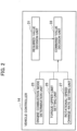
- the vehicle controller 14 includes functional constituent elements that are an engine-combustion-mode determination unit 23, a torque-upper-limit setting unit 25, a rotational-speed change-rate setting unit 27, a required-value decision unit 31, and a command-value decision unit 33.
- the engine-combustion-mode determination unit 23 determines an engine mode of the engine 1 on the basis of a signal received from the engine state sensor 21 and indicating the state of the engine 1 (a signal indicating whether the engine 1 is supplied with fuel, and a signal indicating the engine rotational speed Nr).
- a signal indicating whether the engine 1 is supplied with fuel and a signal indicating the engine rotational speed Nr.
- non-combustion mode refers to a mode in which the engine 1 is not supplied with fuel or air.
- combustion mode refers to a mode in which the engine 1 is supplied with fuel and air, and the engine rotational speed Nr falls within a predetermined rotational-speed range.
- the predetermined rotational-speed range in the “combustion mode” is defined in consideration of characteristics of the engine 1 during firing. For example, the range of the engine rotational speed Nr, within which the engine 1 has improved fuel economy, is defined as a predetermined rotational-speed range.
- the engine 1 When the engine 1 is in the "non-combustion mode", the engine 1 is not supplied with fuel. It is thus necessary to apply an external torque in order to rotate the driving-force output shaft of the engine 1.
- the output shaft of the engine 1 in the "non-combustion mode” is rotated by the generator 4 driven by being supplied with regenerative power generated in the drive motor 6. This makes it possible to forcibly discharge the regenerative power generated in the drive motor 6.
- Motoring control Rotating the output shaft of the engine by the electric motor in the manner as described above is referred to as "motoring control”.
- firing control supplying fuel to the engine 1 and outputting a torque from the output shaft of the engine 1 is referred to as "firing control”.
- the duration of the "non-combustion mode” does not always correspond with the duration of the "motoring control”.
- the duration of the "combustion mode” does not always correspond with the duration of the "firing control”.
- the required-value decision unit 31 decides a required torque Tm to be generated in the drive motor 6 on the basis of the accelerator opening Ac received from the accelerator position sensor 20.
- the required-value decision unit 31 decides a power, obtained by subtracting a power Pb available for supply from the battery 5 to the drive motor 6 from a power needed for the drive motor 6 to generate the required torque Tm, as a required power Pd for the generator 4. However, the required-value decision unit 31 decides the required power Pd as 0 (zero), where the power Pb available for supply from the battery 5 to the drive motor 6 is greater than the power needed for the drive motor 6 to generate the required torque Tm. Due to this decision, the value of the required power Pd for the generator 4 is equal to or greater than zero.
- the required-value decision unit 31 decides a torque needed for the generator 4 to generate the required power Pd as a required torque Ttg (predetermined torque threshold) for the engine 1.
- the required-value decision unit 31 decides a power, obtained by subtracting a power available for supply from the battery 5 to auxiliary devices (not illustrated) installed in the vehicle from a power needed for charging the battery 5 and driving the auxiliary devices, as an auxiliary-device power shortage Pw. However, the required-value decision unit 31 decides the auxiliary-device power shortage Pw as zero, where the power available for supply from the battery 5 to the auxiliary devices installed in the vehicle is greater than the power needed for the auxiliary devices. Due to this decision, the value of the auxiliary-device power shortage Pw is equal to or greater than zero.
- the required-value decision unit 31 decides a torque needed for the generator 4 to generate a total power of the required power Pd and the auxiliary-device power shortage Pw as a required torque Tap for the engine 1.
- the required-value decision unit 31 decides a target rotational speed Ntg of the engine 1 in the "combustion mode".
- the value of the target rotational speed Ntg falls within the predetermined rotational-speed range in the "combustion mode".
- the torque-upper-limit setting unit 25 sets a torque limitation value Tmax (a normal value Tn and a limitation value Tcr), which is an upper limit of the command torque Tc for the engine 1, on the basis of the engine mode determined by the engine-combustion-mode determination unit 23, the engine rotational speed Nr received from the engine state sensor 21, and the target rotational speed Ntg of the engine 1.
- the normal value Tn is a limitation value which is set to ensure safe driving of the engine 1 in consideration of a safety factor and other factors.
- the limitation value Tcr is smaller than the normal value Tn.
- the rotational-speed change-rate setting unit 27 sets a rotational-speed drop rate Rdown (a normal value Rn and a limitation value Rcr) of the engine rotational speed Nr on the basis of the engine mode determined by the engine-combustion-mode determination unit 23, the engine rotational speed Nr received from the engine state sensor 21, and the target rotational speed Ntg of the engine 1.
- the limitation value Rcr set as the rotational-speed drop rate Rdown is different from the normal value Rn.
- the limitation value Rcr may be greater than the normal value Rn or may be smaller than the normal value Rn as necessary.
- the command-value decision unit 33 compares the torque limitation value Tmax set by the torque-upper-limit setting unit 25 with the required torque Tap decided by the required-value decision unit 31, and decides whichever is smaller in value as the command torque Tc for the engine 1.
- the command torque Tc is thus set as a value not exceeding the torque limitation value Tmax.
- the command-value decision unit 33 decides a command rotational speed Nc for the engine 1 on the basis of the engine rotational speed Nr received from the engine state sensor 21, the target rotational speed Ntg decided by the required-value decision unit 31, and the rotational-speed drop rate Rdown set by the rotational-speed change-rate setting unit 27. Specifically, on a condition that the engine rotational speed Nr is decreased toward the target rotational speed Ntg, the command-value decision unit 33 decides the command rotational speed Nc such that the amount of decrease in the engine rotational speed Nr per unit time becomes equal to the rotational-speed drop rate Rdown.
- the vehicle controller 14 controls the engine 1 on the basis of the command torque Tc and the command rotational speed Nc decided for the engine 1 in the manner as described above.
- the torque limitation processing illustrated in Fig. 3 is started when ignition of the vehicle is turned on, and is repeatedly performed until the ignition is turned off. Each time the torque limitation processing illustrated in Fig. 3 is performed, the command-value decision unit 33 decides the command torque Tc and the command rotational speed Nc for the engine 1.
- Step S101 the vehicle controller 14 first determines whether combustion occurs in the engine 1. More specifically, the vehicle controller 14 determines whether the engine 1 is in either the "non-combustion mode" or the "combustion mode". When the engine 1 is in the "combustion mode" (YES at Step S101), the process advances to Step S103. In contrast, when the engine 1 is in the "non-combustion mode" (NO at Step S101), the process advances to Step S121.
- the normal value Tn is set as the torque limitation value Tmax, while the normal value Rn is set as the rotational-speed drop rate Rdown.
- Step S103 the vehicle controller 14 determines whether the engine rotational speed Nr is equal to or lower than a value obtained by adding a predetermined value ⁇ Ne to the target rotational speed Ntg.
- the predetermined value ⁇ Ne is a positive number.
- Step S105 the vehicle controller 14 determines whether the engine rotational speed Nr is equal to or higher than a value obtained by adding a predetermined value ⁇ Ns to the target rotational speed Ntg.
- the predetermined value ⁇ Ns is a positive number.
- the limitation value Tcr is set as the torque limitation value Tmax, while the limitation value Rcr is set as the rotational-speed drop rate Rdown.
- Step S111 the vehicle controller 14 determines whether the value of the required torque Ttg for the engine 1 is greater than a previous torque limitation value Tmz.
- the previous torque limitation value Tmz refers to the previous value of the torque limitation value Tmax when the torque limitation processing illustrated in Fig. 3 is repeatedly performed.
- a predetermined value ⁇ Tcr is added to the previous torque limitation value Tmz.
- the torque limitation value Tmax is incremented by the predetermined value ⁇ Tcr. That is, the torque limitation value Tmax is incremented by the predetermined value ⁇ Tcr per unit step.
- Processes at Steps S111 and S113 are not essential. It is allowable that when the determination is NO at Step S105, the process advances to Step S121.
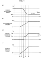
- Fig. 4(a) illustrates a change in the engine rotational speed Nr
- Fig. 4(b) illustrates a change in the accelerator opening Ac
- Fig. 4(c) illustrates a change in the command torque Tc for the engine 1
- Fig. 4(d) illustrates a change in the vehicle driving force FD.
- the timing charts in Figs. 4(a) to 4(d) illustrate a case where during the period before a time t1, the motoring control is executed on the engine 1, at a time t2, the engine 1 starts-up, and during the period after the time t2, the firing control is executed on the engine 1.
- the vehicle driving force FD is a negative driving force (brake force).
- the accelerator pedal is pressed and thereby the accelerator opening Ac begins increasing from zero.
- the engine 1 Since the engine 1 is not supplied with fuel under the motoring control, the engine 1 is in the "non-combustion mode" during the period before the time t1. The engine 1 is in the "combustion mode” during the period after the time t4 which is the timing at which the engine rotational speed Nr becomes the target rotational speed Ntg.
- the time t2 is a timing at which the engine 1 is supplied with fuel and starts driving. At the time t2, the engine 1 is switched from the "non-combustion mode" to the "combustion mode".
- auxiliary-device power shortage Pw is assumed to be zero.
- the engine rotational speed Nr of the engine 1 is higher than the target rotational speed Ntg in the "combustion mode".
- the period from the time t1 to the time t4 is the state transition period from the motoring control to the firing control, during which the engine rotational speed Nr of the engine 1 is decreased.
- the engine rotational speed Nr of the engine 1 is decreased by a torque of the generator 4 to the predetermined rotational-speed range appropriate to the power generation.
- the vehicle driving force FD which has been a brake force under the motoring control, begins increasing in accordance with the accelerator opening Ac.
- the vehicle driving force FD becomes zero at the time t1
- the motoring control is ended.
- the accelerator opening Ac at the time when the vehicle driving force FD becomes zero is called "neutral point".
- the neutral point corresponds to a state where the drive motor 6 does not generate a positive driving force or a negative driving force.
- the torque limitation value Tmax increases from the limitation value Tcr. More specifically, the torque limitation value Tmax is incremented by the predetermined value ⁇ Tcr per unit step. As illustrated in Fig. 4(c) , the command torque Tc is limited by the torque limitation value Tmax, and consequently the command torque Tc is the limitation value set at Step S113 in Fig. 3 during the period from the time t3 to the time t4.
- the reasons why the torque limitation value Tmax is incremented by the predetermined value ⁇ Tcr during the period from the time t3 to the time t4 are that a change in driving force generated by the engine 1 affects the amount of power generated in the generator 4, and affects the feeling of acceleration sensed by vehicle occupants through the vehicle driving force FD in the drive motor 6.
- the rate of change in the torque limitation value Tmax is limited by the predetermined value ⁇ Tcr.
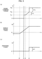
- Fig. 5(a) illustrates a change in engine command torque
- Fig. 5(b) illustrates a change in vehicle driving force
- Fig. 5(c) illustrates a change in additional power.
- the timing charts in Figs. 5(a) to 5(c) are different from the timing charts illustrated in Figs. 4(a) to 4(d) in that the timing charts illustrate the case where the auxiliary-device power shortage Pw is not zero.
- the engine command torque illustrated in Fig. 5(a) is changed in the same manner as illustrated in Fig. 4(c) at and before the time t4.
- the engine command torque is changed differently from that illustrated in Fig. 4(c) after the torque limitation is cancelled at the time t4.
- the auxiliary-device power shortage Pw is not zero, the engine 1 is required to make up for a power shortage in the auxiliary devices.
- the command torque Tc is increased from the required torque Ttg to the required torque Tap.
- This case does not cause any problem despite an abrupt increase in the command torque Tc.
- a change in driving force generated by the engine 1 may affect the feeling of acceleration sensed by vehicle occupants during the period at and before the time t4.
- the change in the command torque Tc after the time t4 does not cause a change in the vehicle driving force FD of the drive motor 6 ( Fig. 5(b) ).
- the change in the command torque Tc after the time t4 is intended to affect the change in additional power Ps obtained by subtracting a power supplied to the drive motor 6 from a power generated by the generator 4.
- the electric device control method and the electric device perform torque limitation to set the torque (the command torque Tc) generated by the engine 1 so as to become lower than the required torque Ttg within a predetermined rotational-speed range for the engine 1 in the "combustion mode".
- This operation can reduce irregular sound from the intake system of the engine 1 generated when the motoring control is shifted to the firing control and the rotational speed of the engine 1 is decreased to the predetermined rotational-speed range by a motor torque.
- the reduction in irregular sound can reduce vehicle occupants' discomfort.
- the engine torque of the engine 1 in the “combustion mode” is increased to the required torque Ttg within the predetermined rotational-speed range. That is, the torque limitation to set the torque (the command torque Tc) generated by the engine 1 so as to become lower than the required torque Ttg during this transition period is intended to limit the engine torque being increased, and does not involve a decrease in the engine torque.
- the torque limitation during the transition period does not involve a decrease in the engine torque, and thus a change in the driving force is insignificant. Accordingly, irregular sound generated from the intake system of the engine 1 can be reduced without occupants having a sense of discomfort.
- the rotational-speed drop rate Rdown (rotational-speed decrease rate) of the engine 1 when the torque limitation is performed may be set higher than the rotational-speed drop rate Rdown of the engine 1 in the "combustion mode".
- This setting can reduce the period during which the engine rotational speed Nr is decreased to a rotational speed within the predetermined rotational-speed range, and can also reduce the duration of irregular sound from the intake system of the engine 1 generated when the motoring control is shifted to the firing control. Consequently, irregular sound from the intake system of the engine 1 can be reduced, and this can reduce vehicle occupants' discomfort.
- the rotational-speed drop rate Rdown (rotational-speed decrease rate) of the engine 1 when the torque limitation is performed may be set lower than the rotational-speed drop rate Rdown of the engine 1 in the "combustion mode". Due to this setting, the engine rotational speed Nr changes smoothly during the period in which the engine rotational speed Nr is decreased to a rotational speed within the predetermined rotational-speed range, so that the level of irregular sound from the intake system of the engine 1 can be decreased. Consequently, irregular sound from the intake system of the engine 1 can be reduced. This can reduce vehicle occupants' discomfort.
- the torque limitation when the difference between the engine rotational speed Nr and the target rotational speed Ntg is below the predetermined value ⁇ Ne, the torque limitation may be cancelled, and the torque generated by the engine 1 may be increased to a required torque for the engine 1. Due to this operation, the state of the engine 1 has changed after the start of torque limitation intended to reduce the irregular sound, and thus the engine 1 can be determined to have reached the state where it is not necessary to continue performing the torque limitation on the engine 1. As a consequence, the torque limitation can be cancelled and the engine 1 can be controlled so as to output a required torque for the engine 1.
- the torque generated by the engine 1 may be limited such that the increase rate of the torque generated by the engine 1 does not exceed the predetermined value ⁇ Tcr (predetermined limitation value).
- This operation can prevent the torque generated by the engine 1 from sharply increasing after the torque limitation is cancelled. Consequently, this can reduce variations in the feeling of acceleration sensed by vehicle occupants through variations in the vehicle driving force FD generated by the drive motor 6.
- a torque generated by the engine 1 in order for the generator 4 to generate the required power Pd needed for driving the vehicle may be set as the predetermined torque threshold. Further, a power, obtained by subtracting the power Pb available for supply from the battery installed in the vehicle from the power needed for the drive motor 6 (second electric motor) to generate the torque needed for driving the vehicle, may be set as the required power Pd needed for driving the vehicle. Due to these settings, the period during which a torque generated by the engine 1 is prevented from sharply increasing after the cancellation of torque limitation can be limited to a period during which the power generated by the generator 4 is increased to the required power Pd.
- the generator 4 can immediately supply power to make up for the auxiliary-device power shortage Pw (a power obtained by subtracting a power available for supply from the battery 5 to auxiliary devices installed in the vehicle from a power needed for charging the battery 5 and driving the auxiliary devices).
- the generator 4 supplies power to make up for the auxiliary-device power shortage Pw so that the battery can be charged immediately and the auxiliary devices can be driven immediately.
- the torque limitation is performed.
- the motoring control executed during deceleration of the vehicle is shifted to the firing control executed during acceleration of the vehicle, and accordingly the engine 1 is shifted from the "non-combustion mode" to the "combustion mode". It is thus possible to more accurately control the timing of performing the torque limitation. Consequently, this can reduce irregular sound from the intake system of the engine 1 generated when the motoring control is shifted to the firing control. Further, the reduction in irregular sound can reduce vehicle occupants' discomfort.
- Respective functions described in the above embodiments may be implemented by one or more processing circuits.
- the processing circuits include programmed processors such as a processor including an electric circuit.
- the processors also include devices such as an application specific integrated circuit (ASIC) and conventional circuit elements that are arranged to execute the functions described in the embodiments.
- ASIC application specific integrated circuit
Description
- The present invention relates to a control method for a series hybrid car and a series hybrid car.
-
Patent Literature 1 discloses a regenerative control device that is capable of switching between motoring control and firing control. In the motoring control, a motor that rotates using regenerative power supplied from a device other than the motor is used to forcibly rotate an engine having its fuel supply shut off, to thereby consume the regenerative power. In the firing control, fuel is supplied to the engine to rotate the engine. - Patent Literature 1: Japanese Patent Laid-Open Publication
JP 2017- 114 206 A
Prior art documentEP 2 990 284 A1 refers to a regenerative control device for a hybrid vehicle that includes a regenerative braking power control unit for prohibiting or limiting execution of first regenerative braking to charge the battery with power generated by the regenerative power generation of the traveling motor generator during deceleration when it is determined that it is necessary to restrict charging of the battery. The regenerative braking power control unit causes both second regenerative braking to transmit rotary driving power to the engine by rotating the power generation motor generator by the power generated by the regenerative power generation, and combustion operation in which fuel is supplied to the engine and the fuel is burned to generate the rotary driving power at the engine, to be executed, under condition where the execution of the first regenerative braking is prohibited or limited. - Prior art document
JP 2006- 132 465 A - However, in the example disclosed in
Patent Literature 1, there is a problem in that irregular sound is generated from an intake system of the engine when the motoring control is shifted to the firing control to decrease the engine rotational speed, having been increased to consume regenerative power during the motoring control, to a predetermined rotational speed by a motor torque. - The present invention has been made in view of the above problems and it is an object of the present invention to provide an electric device control method and an electric device that minimize irregular sound from an intake system of an engine generated when motoring control is shifted to firing control and a rotational speed of the engine is decreased to a predetermined rotational speed by a motor torque.
- The object underlying the present invention is achieved by a control method for a series hybrid car according to
independent claim 1 and by a series hybrid car according toindependent claim 7. Preferred embodiments are defined in the respective dependent claims. - In order to solve the above problems, in an electric device control method and an electric device according to an aspect of the present invention, during a period in which a rotational speed of an internal combustion engine shifting from a non-combustion mode to a combustion mode is decreased to a rotational speed within a predetermined rotational-speed range by a first electric motor, a torque generated by the internal combustion engine is set lower than a required torque within the predetermined rotational-speed range for the internal combustion engine in the combustion mode.
- According to the present invention, it is possible to minimize irregular sound from an intake system of an engine generated when motoring control is shifted to firing control.
-
- [
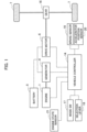
Fig. 1] Fig. 1 is a block diagram illustrating a configuration of a hybrid car including an electric device according to an embodiment of the present invention. - [
Fig. 2] Fig. 2 is a block diagram illustrating functional constituent elements included in a vehicle controller. - [
Fig. 3] Fig. 3 is a flowchart illustrating a process procedure for torque limitation performed by the electric device according to the embodiment of the present invention. - [
Figs. 4] Figs. 4 are timing charts illustrating a first example of torque limitation performed by the electric device according to the embodiment of the present invention, where (a) illustrates a change in engine rotational speed, (b) illustrates a change in accelerator opening, (c) illustrates a change in engine command torque, and (d) illustrates a change in vehicle driving force. - [
Figs. 5] Figs. 5 are timing charts illustrating a second example of torque limitation performed by the electric device according to the embodiment of the present invention, where (a) illustrates a change in engine command torque, (b) illustrates a change in vehicle driving force, and (c) illustrates a change in additional power. - Embodiments of the present invention are described below with reference to the accompanying drawings. In the explanations, like parts are denoted by like reference signs and redundant explanations thereof are omitted.
- A configuration of a hybrid car including an electric device according to an embodiment of the present invention is described with reference to
Fig. 1 . The hybrid car according to the present embodiment includes an engine 1 (internal combustion engine), a generator 4 (first electric motor), abattery 5, a drive motor 6 (second electric motor), and wheels 7 (drive wheels). In the hybrid car, theengine 1 does not drive thewheels 7, but thedrive motor 6 drives thewheels 7 by using power from thebattery 5. Since theengine 1, thebattery 5, thedrive motor 6, and thewheels 7 are connected in series (series connection), the hybrid car is referred to as "series hybrid car". - The
engine 1 is mechanically connected with thegenerator 4. Thegenerator 4 is connected to thebattery 5 such that thegenerator 4 is capable of transmitting and receiving power to and from thebattery 5. Thegenerator 4 and thedrive motor 6 are also connected such that it is possible to transmit and receive power between them. Thebattery 5 and thedrive motor 6 are also connected such that it is possible to transmit and receive power between them. Thedrive motor 6 is mechanically connected with an axle through agear 16. The axle is mechanically connected with thewheels 7. - A driving force of the
engine 1 is transmitted to thegenerator 4, and thegenerator 4 rotates using the driving force of theengine 1 and generates power. When power generated by thegenerator 4 flows to thebattery 5, this power is consumed for charging thebattery 5. When power generated by thegenerator 4 flows to thedrive motor 6, this power is consumed for driving of thedrive motor 6. - The
drive motor 6 is supplied with power from either one or both of thegenerator 4 and thebattery 5. Thedrive motor 6 consumes the supplied power to generate a driving force. The driving force of thedrive motor 6 is transmitted through thegear 16 and the axle to thewheels 7. Thewheels 7 rotate using the driving force of thedrive motor 6, so that the series hybrid car (hereinafter, abbreviated as "vehicle") runs. - In a case, such as during deceleration of the vehicle or when the vehicle is travelling downhill, where a torque is input from the
wheels 7 through the axle and thegear 16 to thedrive motor 6, and thus thedrive motor 6 rotates using the input torque, thedrive motor 6 operates as a generator to generate regenerative power. When regenerative power is generated in thedrive motor 6, a reaction of the torque input to thedrive motor 6 causes a regenerative brake force to be generated on thewheels 7 through thegear 16 and the axle. - When the regenerative power generated in the
drive motor 6 flows to thebattery 5, the regenerative power is consumed to charge thebattery 5. When the regenerative power generated in thedrive motor 6 flows to thegenerator 4, the regenerative power is consumed to drive theengine 1 and thegenerator 4 against a resistance of the engine 1 (engine braking). - The
battery 5 has a charge and discharge function. When thebattery 5 is charged, thebattery 5 stores therein energy of the power supplied from thegenerator 4 or thedrive motor 6. When thebattery 5 is discharged, thebattery 5 supplies the energy stored therein as power to thedrive motor 6. - A power flow between the
generator 4, thebattery 5, and thedrive motor 6 may change depending on the respective states of thebattery 5 and thedrive motor 6, travelling conditions of the vehicle, and other factors such as a power supply-demand status in the entire vehicle including auxiliary devices installed in the vehicle (such as an air-conditioner, a car stereo system, and a navigation system). A power flow between thegenerator 4, thebattery 5, and thedrive motor 6 is determined by control executed by avehicle controller 14 described later. - For example, when the
drive motor 6 needs to generate a driving force, it is allowable that power is supplied from thebattery 5 to thedrive motor 6. When sufficient power cannot be supplied from thebattery 5 to thedrive motor 6, it is allowable to drive theengine 1 to generate power in thegenerator 4, so that in addition to the power from thebattery 5, the power from thegenerator 4 is also supplied to thedrive motor 6. - When charging of the
battery 5 is not completed, it is allowable that regenerative power, generated by thedrive motor 6 during deceleration of the vehicle or when the vehicle is travelling downhill, is supplied from thedrive motor 6 to thebattery 5. Further, in a state where charging of thebattery 5 is not completed, it is allowable to drive theengine 1 to generate power in thegenerator 4 and supply the power from thegenerator 4 to thebattery 5. - When a state of charge (SOC) of the
battery 5 is high, it is allowable that regenerative power, generated by thedrive motor 6 during deceleration of the vehicle or when the vehicle is travelling downhill, is supplied to thegenerator 4. In this case, the regenerative power supplied from thedrive motor 6 to thegenerator 4 is consumed by thegenerator 4 in order to work against the engine braking applied by theengine 1. As a result of this, the regenerative power supplied from thedrive motor 6 to thegenerator 4 is forcibly discharged. - The vehicle further includes a mode switch 17 (a mode SW) that selects one of running modes, a
selection lever 18 that is operated by a driver, abrake sensor 19 that detects a braking force, an accelerator position sensor 20 (APS) that detects an accelerator opening, anengine state sensor 21 that detects a state of the engine, and thevehicle controller 14 that controls the hybrid car in its entirety. Thevehicle controller 14 functions as a control circuit that controls the electric device according to the present embodiment. - The
vehicle controller 14 is electrically connected to each of themode switch 17, theselection lever 18, thebrake sensor 19, theaccelerator position sensor 20, and theengine state sensor 21. Thevehicle controller 14 receives a signal indicating a selected running mode from themode switch 17, receives a signal indicating the selected range from theselection lever 18, receives a signal indicating the brake oil pressure from thebrake sensor 19, and receives a signal indicating an accelerator opening Ac of an accelerator pedal (input device) from theaccelerator position sensor 20. - The
vehicle controller 14 further receives a signal indicating the state of theengine 1 from theengine state sensor 21. Examples of the signal indicating the state of theengine 1 include a signal indicating whether theengine 1 is supplied with fuel, and a signal indicating an engine rotational speed Nr. - Examples of the range that is selectable through the
selection lever 18 include a drive range (D), a brake range (B), a reverse range (R), a neutral range (N), a parking range (P), and the like. - The
vehicle controller 14 is electrically connected to theengine 1, thegenerator 4, and thedrive motor 6 through a signal line. Thevehicle controller 14 controls theengine 1, thegenerator 4, and thedrive motor 6 in order to generate a required torque Tm (a vehicle driving force FD) in thedrive motor 6 in accordance with the accelerator opening Ac. Particularly, thevehicle controller 14 transmits a command torque Tc to theengine 1. - The phrase "transmits a command torque Tc" includes controlling the
engine 1 in such a manner that a torque output by theengine 1 becomes the command torque Tc. For example, the wording "transmits a command torque Tc" includes controlling theengine 1 in such a manner that a torque output by theengine 1 becomes the command torque Tc by changing the throttle opening of theengine 1, changing the air-fuel ratio, and changing the amount of fuel supplied to theengine 1. - The
vehicle controller 14 controls the driving states of theengine 1, thegenerator 4, and thedrive motor 6, and accordingly the states of other auxiliary devices (not illustrated) are determined, so that a power flow between thegenerator 4, thebattery 5, and thedrive motor 6 is determined. - The
vehicle controller 14 can be implemented by, for example, a general-purpose microcomputer including a CPU (central processing unit), a memory, and an input/output unit. A computer program (a control program) that causes the microcomputer to function as thevehicle controller 14 is installed in the microcomputer so that the microcomputer executes the computer program. Due to this program, the general-purpose microcomputer functions as thevehicle controller 14. - In the present embodiment, the example is described in which the
vehicle controller 14 is implemented by software. Apparently, it is also possible to configure thevehicle controller 14 by preparing dedicated hardware to performing each step of information processing described below. It is also allowable to configure each of the units (23, 25, 27, 31, and 33) included in thevehicle controller 14 by each individual hardware. It is further allowable that thevehicle controller 14 is used in combination with an electronic control unit (ECU) to be used for other vehicle-related controls. - Functional constituent elements included in the
vehicle controller 14 are described below with reference toFig. 2 . Thevehicle controller 14 includes functional constituent elements that are an engine-combustion-mode determination unit 23, a torque-upper-limit setting unit 25, a rotational-speed change-rate setting unit 27, a required-value decision unit 31, and a command-value decision unit 33. - The engine-combustion-
mode determination unit 23 determines an engine mode of theengine 1 on the basis of a signal received from theengine state sensor 21 and indicating the state of the engine 1 (a signal indicating whether theengine 1 is supplied with fuel, and a signal indicating the engine rotational speed Nr). There are two possible types of engine modes for theengine 1, that is, "non-combustion mode" and "combustion mode". - The "non-combustion mode" refers to a mode in which the
engine 1 is not supplied with fuel or air. The "combustion mode" refers to a mode in which theengine 1 is supplied with fuel and air, and the engine rotational speed Nr falls within a predetermined rotational-speed range. The predetermined rotational-speed range in the "combustion mode" is defined in consideration of characteristics of theengine 1 during firing. For example, the range of the engine rotational speed Nr, within which theengine 1 has improved fuel economy, is defined as a predetermined rotational-speed range. - When the
engine 1 is in the "non-combustion mode", theengine 1 is not supplied with fuel. It is thus necessary to apply an external torque in order to rotate the driving-force output shaft of theengine 1. The output shaft of theengine 1 in the "non-combustion mode" is rotated by thegenerator 4 driven by being supplied with regenerative power generated in thedrive motor 6. This makes it possible to forcibly discharge the regenerative power generated in thedrive motor 6. - Rotating the output shaft of the engine by the electric motor in the manner as described above is referred to as "motoring control". In contrast, supplying fuel to the
engine 1 and outputting a torque from the output shaft of theengine 1 is referred to as "firing control". The duration of the "non-combustion mode" does not always correspond with the duration of the "motoring control". The duration of the "combustion mode" does not always correspond with the duration of the "firing control". - The required-
value decision unit 31 decides a required torque Tm to be generated in thedrive motor 6 on the basis of the accelerator opening Ac received from theaccelerator position sensor 20. - The required-
value decision unit 31 decides a power, obtained by subtracting a power Pb available for supply from thebattery 5 to thedrive motor 6 from a power needed for thedrive motor 6 to generate the required torque Tm, as a required power Pd for thegenerator 4. However, the required-value decision unit 31 decides the required power Pd as 0 (zero), where the power Pb available for supply from thebattery 5 to thedrive motor 6 is greater than the power needed for thedrive motor 6 to generate the required torque Tm. Due to this decision, the value of the required power Pd for thegenerator 4 is equal to or greater than zero. - Further, the required-
value decision unit 31 decides a torque needed for thegenerator 4 to generate the required power Pd as a required torque Ttg (predetermined torque threshold) for theengine 1. - The required-
value decision unit 31 decides a power, obtained by subtracting a power available for supply from thebattery 5 to auxiliary devices (not illustrated) installed in the vehicle from a power needed for charging thebattery 5 and driving the auxiliary devices, as an auxiliary-device power shortage Pw. However, the required-value decision unit 31 decides the auxiliary-device power shortage Pw as zero, where the power available for supply from thebattery 5 to the auxiliary devices installed in the vehicle is greater than the power needed for the auxiliary devices. Due to this decision, the value of the auxiliary-device power shortage Pw is equal to or greater than zero. - Furthermore, the required-
value decision unit 31 decides a torque needed for thegenerator 4 to generate a total power of the required power Pd and the auxiliary-device power shortage Pw as a required torque Tap for theengine 1. - The required-
value decision unit 31 decides a target rotational speed Ntg of theengine 1 in the "combustion mode". The value of the target rotational speed Ntg falls within the predetermined rotational-speed range in the "combustion mode". - The torque-upper-
limit setting unit 25 sets a torque limitation value Tmax (a normal value Tn and a limitation value Tcr), which is an upper limit of the command torque Tc for theengine 1, on the basis of the engine mode determined by the engine-combustion-mode determination unit 23, the engine rotational speed Nr received from theengine state sensor 21, and the target rotational speed Ntg of theengine 1. The normal value Tn is a limitation value which is set to ensure safe driving of theengine 1 in consideration of a safety factor and other factors. The limitation value Tcr is smaller than the normal value Tn. - The rotational-speed change-
rate setting unit 27 sets a rotational-speed drop rate Rdown (a normal value Rn and a limitation value Rcr) of the engine rotational speed Nr on the basis of the engine mode determined by the engine-combustion-mode determination unit 23, the engine rotational speed Nr received from theengine state sensor 21, and the target rotational speed Ntg of theengine 1. The limitation value Rcr set as the rotational-speed drop rate Rdown is different from the normal value Rn. The limitation value Rcr may be greater than the normal value Rn or may be smaller than the normal value Rn as necessary. - The command-
value decision unit 33 compares the torque limitation value Tmax set by the torque-upper-limit setting unit 25 with the required torque Tap decided by the required-value decision unit 31, and decides whichever is smaller in value as the command torque Tc for theengine 1. The command torque Tc is thus set as a value not exceeding the torque limitation value Tmax. - Further, the command-
value decision unit 33 decides a command rotational speed Nc for theengine 1 on the basis of the engine rotational speed Nr received from theengine state sensor 21, the target rotational speed Ntg decided by the required-value decision unit 31, and the rotational-speed drop rate Rdown set by the rotational-speed change-rate setting unit 27. Specifically, on a condition that the engine rotational speed Nr is decreased toward the target rotational speed Ntg, the command-value decision unit 33 decides the command rotational speed Nc such that the amount of decrease in the engine rotational speed Nr per unit time becomes equal to the rotational-speed drop rate Rdown. - The
vehicle controller 14 controls theengine 1 on the basis of the command torque Tc and the command rotational speed Nc decided for theengine 1 in the manner as described above. - Next, a process procedure for torque limitation performed by the electric device according to the present embodiment is described with reference to the flowchart in
Fig. 3 . - The torque limitation processing illustrated in
Fig. 3 is started when ignition of the vehicle is turned on, and is repeatedly performed until the ignition is turned off. Each time the torque limitation processing illustrated inFig. 3 is performed, the command-value decision unit 33 decides the command torque Tc and the command rotational speed Nc for theengine 1. - As illustrated in
Fig. 3 , at Step S101, thevehicle controller 14 first determines whether combustion occurs in theengine 1. More specifically, thevehicle controller 14 determines whether theengine 1 is in either the "non-combustion mode" or the "combustion mode". When theengine 1 is in the "combustion mode" (YES at Step S101), the process advances to Step S103. In contrast, when theengine 1 is in the "non-combustion mode" (NO at Step S101), the process advances to Step S121. - Because torque limitation is not performed at Step S121, the normal value Tn is set as the torque limitation value Tmax, while the normal value Rn is set as the rotational-speed drop rate Rdown.
- At Step S103, the
vehicle controller 14 determines whether the engine rotational speed Nr is equal to or lower than a value obtained by adding a predetermined value ΔNe to the target rotational speed Ntg. The predetermined value ΔNe is a positive number. When "Nr≤Ntg+ΔNe" is established (YES at Step S103), the process advances to Step S121. When "Nr>Ntg+ΔNe" is established (NO at Step S103), the process advances to Step S105. - At Step S105, the
vehicle controller 14 determines whether the engine rotational speed Nr is equal to or higher than a value obtained by adding a predetermined value ΔNs to the target rotational speed Ntg. The predetermined value ΔNs is a positive number. When "Nr≥Ntg+ΔNs" is established (YES at Step S105), the process advances to Step S107. When "Nr≤Ntg+ΔNs" is established (NO at Step S105), the process advances to Step S111. - Because torque limitation is performed at Step S107, the limitation value Tcr is set as the torque limitation value Tmax, while the limitation value Rcr is set as the rotational-speed drop rate Rdown.
- At Step S111, the
vehicle controller 14 determines whether the value of the required torque Ttg for theengine 1 is greater than a previous torque limitation value Tmz. The previous torque limitation value Tmz refers to the previous value of the torque limitation value Tmax when the torque limitation processing illustrated inFig. 3 is repeatedly performed. When "Ttg>Tmz" is established (YES at Step S111), the process advances to Step S113. When "Ttg≤Tmz" is established (NO at Step S111), the process advances to Step S121. - At Step S113, a predetermined value ΔTcr is added to the previous torque limitation value Tmz. Each time the torque limitation processing illustrated in
Fig. 3 is repeatedly performed, the torque limitation value Tmax is incremented by the predetermined value ΔTcr. That is, the torque limitation value Tmax is incremented by the predetermined value ΔTcr per unit step. - Processes at Steps S111 and S113 are not essential. It is allowable that when the determination is NO at Step S105, the process advances to Step S121.
- Next, a first example of torque limitation performed by the electric device according to the present embodiment is described with reference to the timing charts in
Figs. 4(a) to 4(d). Fig. 4(a) illustrates a change in the engine rotational speed Nr,Fig. 4(b) illustrates a change in the accelerator opening Ac,Fig. 4(c) illustrates a change in the command torque Tc for theengine 1, andFig. 4(d) illustrates a change in the vehicle driving force FD. - The timing charts in
Figs. 4(a) to 4(d) illustrate a case where during the period before a time t1, the motoring control is executed on theengine 1, at a time t2, theengine 1 starts-up, and during the period after the time t2, the firing control is executed on theengine 1. As illustrated inFig. 4(d) , during the period before the time 11, as a result of the motoring control executed on theengine 1, the vehicle driving force FD is a negative driving force (brake force). As illustrated inFig. 4(b) , at a timing of a time t0, the accelerator pedal is pressed and thereby the accelerator opening Ac begins increasing from zero. - Since the
engine 1 is not supplied with fuel under the motoring control, theengine 1 is in the "non-combustion mode" during the period before the time t1. Theengine 1 is in the "combustion mode" during the period after the time t4 which is the timing at which the engine rotational speed Nr becomes the target rotational speed Ntg. - The time t2 is a timing at which the
engine 1 is supplied with fuel and starts driving. At the time t2, theengine 1 is switched from the "non-combustion mode" to the "combustion mode". - For simplicity of description, the auxiliary-device power shortage Pw is assumed to be zero.
- As illustrated in
Fig. 4(a) , under the motoring control, regenerative power supplied from thedrive motor 6 to thegenerator 4 is forcibly discharged. Thus, the engine rotational speed Nr of theengine 1 is higher than the target rotational speed Ntg in the "combustion mode". The period from the time t1 to the time t4 is the state transition period from the motoring control to the firing control, during which the engine rotational speed Nr of theengine 1 is decreased. During the transition from the motoring control to the firing control, while thegenerator 4 generates power, the engine rotational speed Nr of theengine 1 is decreased by a torque of thegenerator 4 to the predetermined rotational-speed range appropriate to the power generation. - When the accelerator opening Ac begins increasing from zero at the time t0, the vehicle driving force FD, which has been a brake force under the motoring control, begins increasing in accordance with the accelerator opening Ac. When the vehicle driving force FD becomes zero at the time t1, it is unnecessary to generate a brake force. Thus, the motoring control is ended. The accelerator opening Ac at the time when the vehicle driving force FD becomes zero is called "neutral point". The neutral point corresponds to a state where the
drive motor 6 does not generate a positive driving force or a negative driving force. - After a lapse of time from the time 11, at the time t2 when the accelerator opening AC reaches a predetermined value at which the
engine 1 starts-up, driving of theengine 1 is started. - From the time t2 at which driving of the
engine 1 is started, if the required torque Ttg greater than the torque limitation value Tmax is output as the command torque Tc, irregular sound is generated from theengine 1. For this reason, it is necessary to perform torque limitation intended to limit the command torque Tc to a torque lower than a normal output torque. - As illustrated in
Fig. 4(a) , at the time t2, "Nr>Ntg+ΔNe" and "Nr≥Ntg+ΔNs" are established. Thus, since torque limitation is started from the time t2, the limitation value Tcr is set as the torque limitation value Tmax, while the limitation value Rcr is set as the rotational-speed drop rate Rdown. As illustrated inFig. 4(c) , the command torque Tc is limited by the torque limitation value Tmax, and consequently the command torque Tc is the limitation value Tcr set at Step S107 inFig. 3 during the period from the time t2 to the time t3. - As described above, whether to perform torque limitation at the timing of driving of the
engine 1 is determined by the engine rotational speed Nr and the target rotational speed Ntg. When "Nr<Ntg+ΔNs" is established (that is, when the engine rotational speed Nr is not significantly higher than the target rotational speed Ntg, or when the engine rotational speed Nr is equal to or lower than the target rotational speed Ntg), torque limitation is not performed. - After a lapse of time from the time t2, the engine rotational speed Nr is decreased, and consequently "Nr=Ntg+ΔNe" is established at the time t3. After the time t3, the torque limitation value Tmax increases from the limitation value Tcr. More specifically, the torque limitation value Tmax is incremented by the predetermined value ΔTcr per unit step. As illustrated in
Fig. 4(c) , the command torque Tc is limited by the torque limitation value Tmax, and consequently the command torque Tc is the limitation value set at Step S113 inFig. 3 during the period from the time t3 to the time t4. - The reasons why the torque limitation value Tmax is incremented by the predetermined value ΔTcr during the period from the time t3 to the time t4 are that a change in driving force generated by the
engine 1 affects the amount of power generated in thegenerator 4, and affects the feeling of acceleration sensed by vehicle occupants through the vehicle driving force FD in thedrive motor 6. In order to reduce variations in the feeling of acceleration sensed by vehicle occupants, the rate of change in the torque limitation value Tmax is limited by the predetermined value ΔTcr. - From the time t3 to the time t4, the command torque Tc is increased by ΔTs. When "Ttg≤Tmz" is established ("Tc=Ttg" is established) at the time t4, the normal value Tn is set as the torque limitation value Tmax, while the normal value Rn is set as the rotational-speed drop rate Rdown. Consequently, the torque limitation is ended.
- Next, a second example of torque limitation performed by the electric device according to the present embodiment is described with reference to the timing charts in
Figs. 5(a) to 5(c). Fig. 5(a) illustrates a change in engine command torque,Fig. 5(b) illustrates a change in vehicle driving force, andFig. 5(c) illustrates a change in additional power. - The timing charts in
Figs. 5(a) to 5(c) are different from the timing charts illustrated inFigs. 4(a) to 4(d) in that the timing charts illustrate the case where the auxiliary-device power shortage Pw is not zero. As compared to the change in engine command torque illustrated inFig. 4(c) , the engine command torque illustrated inFig. 5(a) is changed in the same manner as illustrated inFig. 4(c) at and before the time t4. However, the engine command torque is changed differently from that illustrated inFig. 4(c) after the torque limitation is cancelled at the time t4. When the auxiliary-device power shortage Pw is not zero, theengine 1 is required to make up for a power shortage in the auxiliary devices. Thus, it is necessary to increase the command torque Tc for theengine 1 to the required torque Tap that is greater than the required torque Ttg by ΔTp. - Unlike the case where the command torque Tc is increased from the limitation value Tcr to the required torque Ttg (when incremented by ΔTcr), the command torque Tc is increased from the required torque Ttg to the required torque Tap. This case does not cause any problem despite an abrupt increase in the command torque Tc. A change in driving force generated by the
engine 1 may affect the feeling of acceleration sensed by vehicle occupants during the period at and before the time t4. The change in the command torque Tc after the time t4 does not cause a change in the vehicle driving force FD of the drive motor 6 (Fig. 5(b) ). The change in the command torque Tc after the time t4 is intended to affect the change in additional power Ps obtained by subtracting a power supplied to thedrive motor 6 from a power generated by thegenerator 4. - As illustrated in
Fig. 5(c) , immediately after the time t4, the additional power Ps is increased by ΔP1. As a result of this increase, it is possible for thegenerator 4 to make up for the auxiliary-device power shortage Pw in addition to the required power Pd. InFig. 5(c) , "ΔP1=Pw" holds. - As described above in detail, during the transition period of the engine 1 (internal combustion engine) from the "non-combustion mode" to the "combustion mode" during which the engine rotational speed Nr of the
engine 1 is decreased by the generator 4 (first electric motor) connected to theengine 1 to the target rotational speed Ntg that falls within the predetermined rotational-speed range, the electric device control method and the electric device according to the present embodiment perform torque limitation to set the torque (the command torque Tc) generated by theengine 1 so as to become lower than the required torque Ttg within a predetermined rotational-speed range for theengine 1 in the "combustion mode". This operation can reduce irregular sound from the intake system of theengine 1 generated when the motoring control is shifted to the firing control and the rotational speed of theengine 1 is decreased to the predetermined rotational-speed range by a motor torque. The reduction in irregular sound can reduce vehicle occupants' discomfort. - During the transition period of the engine 1 (internal combustion engine) from the "non-combustion mode" to the "combustion mode", the engine torque of the
engine 1 in the "combustion mode" is increased to the required torque Ttg within the predetermined rotational-speed range. That is, the torque limitation to set the torque (the command torque Tc) generated by theengine 1 so as to become lower than the required torque Ttg during this transition period is intended to limit the engine torque being increased, and does not involve a decrease in the engine torque. In contrast to this, after having reached the required torque Ttg within the predetermined rotational-speed range, if the torque generated by theengine 1 is limited to a torque lower than the required torque Ttg, the engine torque is significantly varied. That is, the torque limitation during the transition period does not involve a decrease in the engine torque, and thus a change in the driving force is insignificant. Accordingly, irregular sound generated from the intake system of theengine 1 can be reduced without occupants having a sense of discomfort. - In the electric device control method and the electric device according to the present embodiment, the rotational-speed drop rate Rdown (rotational-speed decrease rate) of the
engine 1 when the torque limitation is performed may be set higher than the rotational-speed drop rate Rdown of theengine 1 in the "combustion mode". This setting can reduce the period during which the engine rotational speed Nr is decreased to a rotational speed within the predetermined rotational-speed range, and can also reduce the duration of irregular sound from the intake system of theengine 1 generated when the motoring control is shifted to the firing control. Consequently, irregular sound from the intake system of theengine 1 can be reduced, and this can reduce vehicle occupants' discomfort. - Further, in the electric device control method and the electric device according to the present embodiment, the rotational-speed drop rate Rdown (rotational-speed decrease rate) of the
engine 1 when the torque limitation is performed may be set lower than the rotational-speed drop rate Rdown of theengine 1 in the "combustion mode". Due to this setting, the engine rotational speed Nr changes smoothly during the period in which the engine rotational speed Nr is decreased to a rotational speed within the predetermined rotational-speed range, so that the level of irregular sound from the intake system of theengine 1 can be decreased. Consequently, irregular sound from the intake system of theengine 1 can be reduced. This can reduce vehicle occupants' discomfort. - In the electric device control method and the electric device according to the present embodiment, when the difference between the engine rotational speed Nr and the target rotational speed Ntg is below the predetermined value ΔNe, the torque limitation may be cancelled, and the torque generated by the
engine 1 may be increased to a required torque for theengine 1. Due to this operation, the state of theengine 1 has changed after the start of torque limitation intended to reduce the irregular sound, and thus theengine 1 can be determined to have reached the state where it is not necessary to continue performing the torque limitation on theengine 1. As a consequence, the torque limitation can be cancelled and theengine 1 can be controlled so as to output a required torque for theengine 1. - Further, in the electric device control method and the electric device according to the present embodiment, after the torque limitation is cancelled, until the torque generated by the
engine 1 is increased to the required torque Ttg (predetermined torque threshold), the torque generated by theengine 1 may be limited such that the increase rate of the torque generated by theengine 1 does not exceed the predetermined value ΔTcr (predetermined limitation value). This operation can prevent the torque generated by theengine 1 from sharply increasing after the torque limitation is cancelled. Consequently, this can reduce variations in the feeling of acceleration sensed by vehicle occupants through variations in the vehicle driving force FD generated by thedrive motor 6. - In the electric device control method and the electric device according to the present embodiment, a torque generated by the
engine 1 in order for thegenerator 4 to generate the required power Pd needed for driving the vehicle may be set as the predetermined torque threshold. Further, a power, obtained by subtracting the power Pb available for supply from the battery installed in the vehicle from the power needed for the drive motor 6 (second electric motor) to generate the torque needed for driving the vehicle, may be set as the required power Pd needed for driving the vehicle. Due to these settings, the period during which a torque generated by theengine 1 is prevented from sharply increasing after the cancellation of torque limitation can be limited to a period during which the power generated by thegenerator 4 is increased to the required power Pd. As a result of this, it is possible to sharply increase the torque generated by theengine 1 after the power generated by thegenerator 4 is increased to the required power Pd. Also, while variations in the feeling of acceleration sensed by vehicle occupants are reduced, thegenerator 4 can immediately supply power to make up for the auxiliary-device power shortage Pw (a power obtained by subtracting a power available for supply from thebattery 5 to auxiliary devices installed in the vehicle from a power needed for charging thebattery 5 and driving the auxiliary devices). Thegenerator 4 supplies power to make up for the auxiliary-device power shortage Pw so that the battery can be charged immediately and the auxiliary devices can be driven immediately. - In the electric device control method and the electric device according to the present embodiment, when the vehicle shifts from deceleration to acceleration, the torque limitation is performed. The motoring control executed during deceleration of the vehicle is shifted to the firing control executed during acceleration of the vehicle, and accordingly the
engine 1 is shifted from the "non-combustion mode" to the "combustion mode". It is thus possible to more accurately control the timing of performing the torque limitation. Consequently, this can reduce irregular sound from the intake system of theengine 1 generated when the motoring control is shifted to the firing control. Further, the reduction in irregular sound can reduce vehicle occupants' discomfort. - Respective functions described in the above embodiments may be implemented by one or more processing circuits. The processing circuits include programmed processors such as a processor including an electric circuit. The processors also include devices such as an application specific integrated circuit (ASIC) and conventional circuit elements that are arranged to execute the functions described in the embodiments.
-
- 1
- engine
- 4
- generator
- 5
- battery
- 6
- drive motor
- 7
- wheels
- 14
- vehicle controller
- 16
- gear
- 17
- mode switch
- 18
- selection lever
- 19
- brake sensor
- 20
- accelerator position sensor
- 21
- engine state sensor
- 23
- engine-combustion-mode determination unit
- 25
- torque-upper-limit setting unit
- 27
- rotational-speed change-rate setting unit
- 31
- required-value decision unit
- 33
- command-value decision unit
Claims (7)
- A control method for a series hybrid car, wherein:- the series hybrid car comprises an internal combustion engine (1), a first electric motor (4) that is connected to the internal combustion engine (1), a battery (5), a drive motor (6), wheels (7) which are connected in series, as well as an electric device that comprises a vehicle controller which is configured to control the series hybrid car in its entirety,- the vehicle controller performs torque limitation during a period in which the internal combustion engine (1) is shifted from a non-combustion mode to a combustion mode, and a rotational speed (Nr) of the internal combustion engine (1) is decreased by the first electric motor (4) to a rotational speed (Ntg) within a predetermined rotational-speed range in the combustion mode, and- the torque limitation is performed to set a torque (Tc) generated by the internal combustion engine (1) so as to become lower than a required torque (Ttg) within the predetermined rotational-speed range for the internal combustion engine (1) in the combustion mode.
- The control method according to claim 1, wherein when a difference between a rotational speed (Nr) of the internal combustion engine (1) and a target rotational speed (Ntg) that falls within the predetermined rotational-speed range is below a predetermined value (ΔNe), the torque limitation is cancelled, and a torque (Tc) generated by the internal combustion engine (1) is increased to the required torque.
- The control method according to claim 2, wherein after the torque limitation is cancelled, until a torque (Tc) generated by the internal combustion engine (1) is increased to a predetermined torque threshold (Ttg), a torque (Tc)_generated by the internal combustion engine (1) is limited such that an increase rate of the torque (Tc) generated by the internal combustion engine (1) does not exceed a predetermined limitation value (ΔTcr).
- The control method according to claim 3, wherein the predetermined torque threshold (Ttg) is a torque (Tc) generated by the internal combustion engine (1) in order for the first electric motor (4) to generate a required power (Pd) needed for driving a vehicle having the electric device installed therein.
- The control method according to claim 4, wherein the required power (Pd) is a power obtained by subtracting a power (Pb) available for supply from a battery installed in the vehicle from a power needed for a second electric motor (6) to generate a torque needed for driving the vehicle.
- The control method according to any one of the preceding claims, wherein when a vehicle having the electric device installed therein shifts from deceleration to acceleration, the torque limitation is performed.
- A series hybrid car, wherein:- the series hybrid car comprises an internal combustion engine (1), a first electric motor (4) that is connected to the internal combustion engine (1), a battery (5), a drive motor (6), wheels (7) which are connected in series as well as an electric device that comprises a vehicle controller which is configured to control the series hybrid car in its entirety,- the vehicle controller is configured to perform torque limitation during a period in which the internal combustion engine (1) is shifted from a non-combustion mode to a combustion mode, and a rotational speed (Nr) of the internal combustion engine (1) is decreased by the first electric motor (4) to a rotational speed (Ntg) within a predetermined rotational-speed range in the combustion mode, and- the vehicle controller is further configured such that the torque limitation is performed to set a torque (Tc) generated by the internal combustion engine (1) so as to become lower than a required torque (Ttg) within the predetermined rotational-speed range for the internal combustion engine (1) in the combustion mode.
Applications Claiming Priority (1)
| Application Number | Priority Date | Filing Date | Title |
|---|---|---|---|
| PCT/JP2017/045176 WO2019116559A1 (en) | 2017-12-15 | 2017-12-15 | Electric device control method and electric device |
Publications (3)
| Publication Number | Publication Date |
|---|---|
| EP3725623A1 EP3725623A1 (en) | 2020-10-21 |
| EP3725623A4 EP3725623A4 (en) | 2020-12-16 |
| EP3725623B1 true EP3725623B1 (en) | 2024-03-13 |
Family
ID=66819153
Family Applications (1)
| Application Number | Title | Priority Date | Filing Date |
|---|---|---|---|
| EP17934615.0A Active EP3725623B1 (en) | 2017-12-15 | 2017-12-15 | Electric device control method and electric device |
Country Status (9)
| Country | Link |
|---|---|
| US (1) | US11312362B2 (en) |
| EP (1) | EP3725623B1 (en) |
| JP (1) | JP6879383B2 (en) |
| KR (1) | KR102270995B1 (en) |
| CN (1) | CN111479740B (en) |
| BR (1) | BR112020011808A2 (en) |
| MX (1) | MX2020006154A (en) |
| RU (1) | RU2748924C1 (en) |
| WO (1) | WO2019116559A1 (en) |
Family Cites Families (17)
| Publication number | Priority date | Publication date | Assignee | Title |
|---|---|---|---|---|
| JP2004242450A (en) * | 2003-02-07 | 2004-08-26 | Nissan Motor Co Ltd | Controller for hybrid vehicle |
| JP3841052B2 (en) | 2003-02-17 | 2006-11-01 | 日産自動車株式会社 | Control device for hybrid vehicle |
| JP2006132465A (en) | 2004-11-08 | 2006-05-25 | Toyota Motor Corp | Hybrid car and method of controlling the same |
| US8112208B2 (en) * | 2009-05-28 | 2012-02-07 | Ford Global Technologies, Llc | Engine speed reduction preparatory to an engine restart |
| US8626424B2 (en) * | 2009-08-05 | 2014-01-07 | GM Global Technology Operations LLC | Active coast and cruise control system and methods |
| JP5561435B2 (en) * | 2011-06-30 | 2014-07-30 | 日産自動車株式会社 | Control device for hybrid vehicle |
| JP2013071603A (en) * | 2011-09-28 | 2013-04-22 | Toyota Motor Corp | Control device for hybrid vehicle |
| JP2013107524A (en) * | 2011-11-22 | 2013-06-06 | Toyota Motor Corp | Power output device |
| CN104185583B (en) * | 2012-03-16 | 2016-12-07 | 日产自动车株式会社 | Hybrid power drives driving dynamic control device and driving control method of electric automobile |
| WO2014006717A1 (en) * | 2012-07-05 | 2014-01-09 | トヨタ自動車株式会社 | Control device for hybrid vehicle |
| JP5974796B2 (en) * | 2012-10-05 | 2016-08-23 | トヨタ自動車株式会社 | Hybrid vehicle and control method of hybrid vehicle |
| US9604528B2 (en) * | 2013-01-24 | 2017-03-28 | Toyota Jidosha Kabushiki Kaisha | Control apparatus for hybrid vehicle |
| CN105246748B (en) * | 2013-05-31 | 2017-07-28 | 丰田自动车株式会社 | The control device of motor vehicle driven by mixed power |
| JP6171873B2 (en) * | 2013-11-13 | 2017-08-02 | マツダ株式会社 | Control device for hybrid vehicle |
| JP6500368B2 (en) * | 2014-08-27 | 2019-04-17 | 三菱自動車工業株式会社 | Regenerative control device for hybrid vehicle |
| JP2017114206A (en) * | 2015-12-22 | 2017-06-29 | 三菱自動車工業株式会社 | Regeneration control apparatus |
| JP6617732B2 (en) * | 2017-02-17 | 2019-12-11 | トヨタ自動車株式会社 | Vehicle shift control device |
-
2017
- 2017-12-15 WO PCT/JP2017/045176 patent/WO2019116559A1/en unknown
- 2017-12-15 JP JP2019558849A patent/JP6879383B2/en active Active
- 2017-12-15 US US16/771,143 patent/US11312362B2/en active Active
- 2017-12-15 KR KR1020207017091A patent/KR102270995B1/en active IP Right Grant
- 2017-12-15 BR BR112020011808-7A patent/BR112020011808A2/en active Search and Examination
- 2017-12-15 MX MX2020006154A patent/MX2020006154A/en unknown
- 2017-12-15 EP EP17934615.0A patent/EP3725623B1/en active Active
- 2017-12-15 CN CN201780097725.9A patent/CN111479740B/en active Active
- 2017-12-15 RU RU2020123238A patent/RU2748924C1/en active
Also Published As
| Publication number | Publication date |
|---|---|
| KR20200086715A (en) | 2020-07-17 |
| EP3725623A4 (en) | 2020-12-16 |
| WO2019116559A1 (en) | 2019-06-20 |
| US11312362B2 (en) | 2022-04-26 |
| KR102270995B1 (en) | 2021-07-02 |
| BR112020011808A2 (en) | 2020-11-17 |
| US20210162981A1 (en) | 2021-06-03 |
| CN111479740B (en) | 2023-02-28 |
| EP3725623A1 (en) | 2020-10-21 |
| RU2748924C1 (en) | 2021-06-01 |
| CN111479740A (en) | 2020-07-31 |
| JPWO2019116559A1 (en) | 2021-01-14 |
| MX2020006154A (en) | 2020-08-13 |
| JP6879383B2 (en) | 2021-06-02 |
Similar Documents
| Publication | Publication Date | Title |
|---|---|---|
| EP2696112B1 (en) | Gear shift indication device | |
| US6494809B1 (en) | Engine control apparatus and engine control method | |
| EP2468598B1 (en) | Vehicle and control method therefor | |
| EP2789514B1 (en) | Hybrid-vehicle control device | |
| EP3725577B1 (en) | Catalyst warm-up control method for hybrid vehicle and catalyst warm-up control apparatus for hybrid vehicle | |
| US20050241868A1 (en) | Vehicle control device, car having the device, and method of controlling the car | |
| WO2009109826A1 (en) | Control apparatus and method for controlling a hybrid vehicle | |
| US20100100263A1 (en) | Vehicle and driving system for vehicle installation | |
| US20100222949A1 (en) | Vehicle and method for controlling the same | |
| JP5060076B2 (en) | Control method of engine in vehicle | |
| US11505071B2 (en) | Regenerative braking control method and regenerative braking control device | |
| JPWO2019116576A1 (en) | Hybrid vehicle control method and control device | |
| JP2011068211A (en) | Hybrid vehicle and method of controlling the same | |
| JP3999786B2 (en) | DRIVE DEVICE, VEHICLE MOUNTING THE SAME, POWER OUTPUT DEVICE, AND DRIVE DEVICE CONTROL METHOD | |
| EP3725623B1 (en) | Electric device control method and electric device | |
| JP5741068B2 (en) | Electric vehicle | |
| JP2004211575A (en) | Control device for vehicle | |
| JP3998002B2 (en) | Hybrid vehicle and control method thereof | |
| EP3895946B1 (en) | Vehicle control method and vehicle control device | |
| WO2010073328A1 (en) | Vehicle control device | |
| JP2007202264A (en) | Vehicle and controlling method therefor | |
| CN112389409A (en) | Hybrid vehicle | |
| JP2005051833A (en) | Vehicle and method for controlling the same | |
| JP2017115679A (en) | Idling stop device | |
| JP2012148652A (en) | Hybrid vehicle |
Legal Events
| Date | Code | Title | Description |
|---|---|---|---|
| STAA | Information on the status of an ep patent application or granted ep patent |
Free format text: STATUS: THE INTERNATIONAL PUBLICATION HAS BEEN MADE |
|
| PUAI | Public reference made under article 153(3) epc to a published international application that has entered the european phase |
Free format text: ORIGINAL CODE: 0009012 |
|
| STAA | Information on the status of an ep patent application or granted ep patent |
Free format text: STATUS: REQUEST FOR EXAMINATION WAS MADE |
|
| 17P | Request for examination filed |
Effective date: 20200610 |
|
| AK | Designated contracting states |
Kind code of ref document: A1 Designated state(s): AL AT BE BG CH CY CZ DE DK EE ES FI FR GB GR HR HU IE IS IT LI LT LU LV MC MK MT NL NO PL PT RO RS SE SI SK SM TR |
|
| AX | Request for extension of the european patent |
Extension state: BA ME |
|
| A4 | Supplementary search report drawn up and despatched |
Effective date: 20201112 |
|
| RIC1 | Information provided on ipc code assigned before grant |
Ipc: B60W 30/20 20060101ALI20201106BHEP Ipc: B60K 6/46 20071001ALI20201106BHEP Ipc: B60W 20/14 20160101ALI20201106BHEP Ipc: B60W 10/06 20060101ALI20201106BHEP Ipc: B60W 10/24 20060101ALI20201106BHEP Ipc: B60W 30/192 20120101ALI20201106BHEP Ipc: B60W 60/00 20200101ALI20201106BHEP Ipc: B60W 10/08 20060101ALI20201106BHEP Ipc: B60W 20/17 20160101AFI20201106BHEP |
|
| DAV | Request for validation of the european patent (deleted) | ||
| DAX | Request for extension of the european patent (deleted) | ||
| STAA | Information on the status of an ep patent application or granted ep patent |
Free format text: STATUS: EXAMINATION IS IN PROGRESS |
|
| 17Q | First examination report despatched |
Effective date: 20220502 |
|
| REG | Reference to a national code |
Ref country code: DE Ref legal event code: R079 Ref document number: 602017080114 Country of ref document: DE Free format text: PREVIOUS MAIN CLASS: B60W0020170000 Ipc: B60K0006260000 Ref country code: DE Ref legal event code: R079 Free format text: PREVIOUS MAIN CLASS: B60W0020170000 Ipc: B60K0006260000 |
|
| REG | Reference to a national code |
Ref country code: DE Ref legal event code: R079 Ref document number: 602017080114 Country of ref document: DE Free format text: PREVIOUS MAIN CLASS: B60K0006260000 Ipc: B60W0020400000 Ref country code: DE Ref legal event code: R079 Free format text: PREVIOUS MAIN CLASS: B60K0006260000 Ipc: B60W0020400000 |
|
| GRAJ | Information related to disapproval of communication of intention to grant by the applicant or resumption of examination proceedings by the epo deleted |
Free format text: ORIGINAL CODE: EPIDOSDIGR1 |
|
| GRAP | Despatch of communication of intention to grant a patent |
Free format text: ORIGINAL CODE: EPIDOSNIGR1 |
|
| GRAP | Despatch of communication of intention to grant a patent |
Free format text: ORIGINAL CODE: EPIDOSNIGR1 |
|
| STAA | Information on the status of an ep patent application or granted ep patent |
Free format text: STATUS: GRANT OF PATENT IS INTENDED |
|
| RIC1 | Information provided on ipc code assigned before grant |
Ipc: B60W 60/00 20200101ALI20231212BHEP Ipc: B60W 30/20 20060101ALI20231212BHEP Ipc: B60W 30/192 20120101ALI20231212BHEP Ipc: B60W 10/24 20060101ALI20231212BHEP Ipc: B60W 10/06 20060101ALI20231212BHEP Ipc: B60W 20/17 20160101ALI20231212BHEP Ipc: B60W 20/14 20160101ALI20231212BHEP Ipc: B60W 10/08 20060101ALI20231212BHEP Ipc: B60K 6/46 20071001ALI20231212BHEP Ipc: B60K 6/26 20071001AFI20231212BHEP |
|
| RIC1 | Information provided on ipc code assigned before grant |
Ipc: B60K 6/26 20071001ALI20231221BHEP Ipc: B60W 60/00 20200101ALI20231221BHEP Ipc: B60W 30/20 20060101ALI20231221BHEP Ipc: B60W 30/192 20120101ALI20231221BHEP Ipc: B60W 10/24 20060101ALI20231221BHEP Ipc: B60W 10/06 20060101ALI20231221BHEP Ipc: B60W 20/17 20160101ALI20231221BHEP Ipc: B60W 20/14 20160101ALI20231221BHEP Ipc: B60W 10/08 20060101ALI20231221BHEP Ipc: B60K 6/46 20071001ALI20231221BHEP Ipc: B60W 30/18 20120101ALI20231221BHEP Ipc: B60W 20/40 20160101AFI20231221BHEP |
|
| INTG | Intention to grant announced |
Effective date: 20240109 |
|
| GRAS | Grant fee paid |
Free format text: ORIGINAL CODE: EPIDOSNIGR3 |
|
| GRAA | (expected) grant |
Free format text: ORIGINAL CODE: 0009210 |
|
| STAA | Information on the status of an ep patent application or granted ep patent |
Free format text: STATUS: THE PATENT HAS BEEN GRANTED |
|
| AK | Designated contracting states |
Kind code of ref document: B1 Designated state(s): AL AT BE BG CH CY CZ DE DK EE ES FI FR GB GR HR HU IE IS IT LI LT LU LV MC MK MT NL NO PL PT RO RS SE SI SK SM TR |
|
| REG | Reference to a national code |
Ref country code: GB Ref legal event code: FG4D |
|
| REG | Reference to a national code |
Ref country code: CH Ref legal event code: EP |
|
| REG | Reference to a national code |
Ref country code: DE Ref legal event code: R096 Ref document number: 602017080114 Country of ref document: DE |