WO2019088106A1 - 磁性粒子収集方法及び試験セット - Google Patents
磁性粒子収集方法及び試験セット Download PDFInfo
- Publication number
- WO2019088106A1 WO2019088106A1 PCT/JP2018/040348 JP2018040348W WO2019088106A1 WO 2019088106 A1 WO2019088106 A1 WO 2019088106A1 JP 2018040348 W JP2018040348 W JP 2018040348W WO 2019088106 A1 WO2019088106 A1 WO 2019088106A1
- Authority
- WO
- WIPO (PCT)
- Prior art keywords
- magnetic
- liquid agent
- liquid
- container
- lid
- Prior art date
Links
Images


Classifications
-
- G—PHYSICS
- G01—MEASURING; TESTING
- G01N—INVESTIGATING OR ANALYSING MATERIALS BY DETERMINING THEIR CHEMICAL OR PHYSICAL PROPERTIES
- G01N33/00—Investigating or analysing materials by specific methods not covered by groups G01N1/00 - G01N31/00
- G01N33/48—Biological material, e.g. blood, urine; Haemocytometers
- G01N33/50—Chemical analysis of biological material, e.g. blood, urine; Testing involving biospecific ligand binding methods; Immunological testing
- G01N33/53—Immunoassay; Biospecific binding assay; Materials therefor
- G01N33/543—Immunoassay; Biospecific binding assay; Materials therefor with an insoluble carrier for immobilising immunochemicals
- G01N33/54313—Immunoassay; Biospecific binding assay; Materials therefor with an insoluble carrier for immobilising immunochemicals the carrier being characterised by its particulate form
- G01N33/54326—Magnetic particles
-
- B—PERFORMING OPERATIONS; TRANSPORTING
- B03—SEPARATION OF SOLID MATERIALS USING LIQUIDS OR USING PNEUMATIC TABLES OR JIGS; MAGNETIC OR ELECTROSTATIC SEPARATION OF SOLID MATERIALS FROM SOLID MATERIALS OR FLUIDS; SEPARATION BY HIGH-VOLTAGE ELECTRIC FIELDS
- B03C—MAGNETIC OR ELECTROSTATIC SEPARATION OF SOLID MATERIALS FROM SOLID MATERIALS OR FLUIDS; SEPARATION BY HIGH-VOLTAGE ELECTRIC FIELDS
- B03C1/00—Magnetic separation
- B03C1/005—Pretreatment specially adapted for magnetic separation
- B03C1/01—Pretreatment specially adapted for magnetic separation by addition of magnetic adjuvants
-
- B—PERFORMING OPERATIONS; TRANSPORTING
- B03—SEPARATION OF SOLID MATERIALS USING LIQUIDS OR USING PNEUMATIC TABLES OR JIGS; MAGNETIC OR ELECTROSTATIC SEPARATION OF SOLID MATERIALS FROM SOLID MATERIALS OR FLUIDS; SEPARATION BY HIGH-VOLTAGE ELECTRIC FIELDS
- B03C—MAGNETIC OR ELECTROSTATIC SEPARATION OF SOLID MATERIALS FROM SOLID MATERIALS OR FLUIDS; SEPARATION BY HIGH-VOLTAGE ELECTRIC FIELDS
- B03C1/00—Magnetic separation
- B03C1/02—Magnetic separation acting directly on the substance being separated
- B03C1/025—High gradient magnetic separators
- B03C1/031—Component parts; Auxiliary operations
- B03C1/033—Component parts; Auxiliary operations characterised by the magnetic circuit
- B03C1/0332—Component parts; Auxiliary operations characterised by the magnetic circuit using permanent magnets
-
- B—PERFORMING OPERATIONS; TRANSPORTING
- B03—SEPARATION OF SOLID MATERIALS USING LIQUIDS OR USING PNEUMATIC TABLES OR JIGS; MAGNETIC OR ELECTROSTATIC SEPARATION OF SOLID MATERIALS FROM SOLID MATERIALS OR FLUIDS; SEPARATION BY HIGH-VOLTAGE ELECTRIC FIELDS
- B03C—MAGNETIC OR ELECTROSTATIC SEPARATION OF SOLID MATERIALS FROM SOLID MATERIALS OR FLUIDS; SEPARATION BY HIGH-VOLTAGE ELECTRIC FIELDS
- B03C1/00—Magnetic separation
- B03C1/02—Magnetic separation acting directly on the substance being separated
- B03C1/28—Magnetic plugs and dipsticks
- B03C1/286—Magnetic plugs and dipsticks disposed at the inner circumference of a recipient, e.g. magnetic drain bolt
-
- B—PERFORMING OPERATIONS; TRANSPORTING
- B03—SEPARATION OF SOLID MATERIALS USING LIQUIDS OR USING PNEUMATIC TABLES OR JIGS; MAGNETIC OR ELECTROSTATIC SEPARATION OF SOLID MATERIALS FROM SOLID MATERIALS OR FLUIDS; SEPARATION BY HIGH-VOLTAGE ELECTRIC FIELDS
- B03C—MAGNETIC OR ELECTROSTATIC SEPARATION OF SOLID MATERIALS FROM SOLID MATERIALS OR FLUIDS; SEPARATION BY HIGH-VOLTAGE ELECTRIC FIELDS
- B03C2201/00—Details of magnetic or electrostatic separation
- B03C2201/18—Magnetic separation whereby the particles are suspended in a liquid
-
- B—PERFORMING OPERATIONS; TRANSPORTING
- B03—SEPARATION OF SOLID MATERIALS USING LIQUIDS OR USING PNEUMATIC TABLES OR JIGS; MAGNETIC OR ELECTROSTATIC SEPARATION OF SOLID MATERIALS FROM SOLID MATERIALS OR FLUIDS; SEPARATION BY HIGH-VOLTAGE ELECTRIC FIELDS
- B03C—MAGNETIC OR ELECTROSTATIC SEPARATION OF SOLID MATERIALS FROM SOLID MATERIALS OR FLUIDS; SEPARATION BY HIGH-VOLTAGE ELECTRIC FIELDS
- B03C2201/00—Details of magnetic or electrostatic separation
- B03C2201/26—Details of magnetic or electrostatic separation for use in medical applications
-
- B—PERFORMING OPERATIONS; TRANSPORTING
- B03—SEPARATION OF SOLID MATERIALS USING LIQUIDS OR USING PNEUMATIC TABLES OR JIGS; MAGNETIC OR ELECTROSTATIC SEPARATION OF SOLID MATERIALS FROM SOLID MATERIALS OR FLUIDS; SEPARATION BY HIGH-VOLTAGE ELECTRIC FIELDS
- B03C—MAGNETIC OR ELECTROSTATIC SEPARATION OF SOLID MATERIALS FROM SOLID MATERIALS OR FLUIDS; SEPARATION BY HIGH-VOLTAGE ELECTRIC FIELDS
- B03C2201/00—Details of magnetic or electrostatic separation
- B03C2201/28—Parts being easily removable for cleaning purposes
-
- G—PHYSICS
- G01—MEASURING; TESTING
- G01N—INVESTIGATING OR ANALYSING MATERIALS BY DETERMINING THEIR CHEMICAL OR PHYSICAL PROPERTIES
- G01N2446/00—Magnetic particle immunoreagent carriers
- G01N2446/60—Magnetic particle immunoreagent carriers the magnetic material being dispersed in a medium other than the main solvent prior to incorporation into the polymer particle
- G01N2446/62—Magnetic material dispersed in water drop
-
- G—PHYSICS
- G01—MEASURING; TESTING
- G01N—INVESTIGATING OR ANALYSING MATERIALS BY DETERMINING THEIR CHEMICAL OR PHYSICAL PROPERTIES
- G01N2446/00—Magnetic particle immunoreagent carriers
- G01N2446/80—Magnetic particle immunoreagent carriers characterised by the agent used to coat the magnetic particles, e.g. lipids
-
- G—PHYSICS
- G01—MEASURING; TESTING
- G01N—INVESTIGATING OR ANALYSING MATERIALS BY DETERMINING THEIR CHEMICAL OR PHYSICAL PROPERTIES
- G01N33/00—Investigating or analysing materials by specific methods not covered by groups G01N1/00 - G01N31/00
- G01N33/48—Biological material, e.g. blood, urine; Haemocytometers
- G01N33/50—Chemical analysis of biological material, e.g. blood, urine; Testing involving biospecific ligand binding methods; Immunological testing
- G01N33/53—Immunoassay; Biospecific binding assay; Materials therefor
- G01N33/569—Immunoassay; Biospecific binding assay; Materials therefor for microorganisms, e.g. protozoa, bacteria, viruses
- G01N33/56911—Bacteria
Definitions
- the present invention relates to a test device using magnetic particles.
- Magnetic particles are widely used as means for separating target components from a certain sample. Specifically, a method of separating target components such as genes and biomarkers from a liquid sample by magnetic particles and detecting the separated target components (for example, Patent Documents 1 and 2), separating and separating target components such as bacteria Methods of detecting the target component (for example, Patent Document 3), or methods of selecting desired cells using magnetic particles and culturing the selected cells (for example, Patent Document 4) are widely known.
- an external magnetic field such as a magnetic stand (e.g., Patent Document 5) or a magnetic field generating device such as an electromagnet (e.g., Patent Document 6) is used as a means for recovering magnetic particles having a target component It was usual to use
- a method of separating a target component using magnetic particles is widely used, for example, in a method of detecting a gene.
- Such gene detection methods have certain needs in the medical field, the agricultural field, and the food and drink field.
- the problem to be solved by the present invention is to provide means for improving the simplicity and speed of the test using magnetic particles.
- the magnetic particles are coagulated on the wall and bottom of the container by an external magnetic field, the supernatant of the liquid sample is removed, washing is performed if necessary, and then the external magnetic field is released.
- the magnetic particles are then resuspended in a detection solution or the like. That is, since the process of removing the supernatant involves the movement of the liquid sample, if the liquid sample is contaminating or infectious, contamination, inspection, etc., due to scattering of the liquid sample or diffusion of the aerosol. At risk of infection in In view of such problems, it is an object of the present invention to provide a technique for reducing the risk of contamination and infection in a test using magnetic particles.
- the present invention for solving the above problems comprises the steps of: suspending magnetic particles in a liquid sample; and fixing the target component on the magnetic particles; Recovering the magnetic collection means from the liquid sample after bringing the magnetic sample into contact with the magnetic collection means and causing the magnetic particles to which the target component is fixed to be attached to the magnetic collection means by magnetism; The magnetic collection means to which the magnetic particles are attached is brought into contact with a solution acting on the target component, and the magnetic particles are attached to the magnetic collection means, and the action step of causing the liquid to act on the target component Is a method characterized by
- the solution is allowed to act on the target component in a state where the magnetic particles are attached to the magnetic collection means without resuspending the magnetic particles in the solution, so that the simplicity and rapidity are excellent.
- the magnetic collecting means is provided on the back side of the lid
- the liquid agent is accommodated in a liquid agent container having an opening that can be sealed by the lid.
- the operation process may be performed by sealing the opening of the liquid agent storage container with the lid and bringing the magnetic collection means provided on the back surface side of the lid into contact with the liquid agent.
- the magnetic particles are brought into contact with the liquid agent in a one-step operation of sealing the liquid agent container with the lid, and the liquid agent is caused to act on the target component, and the object dissolved in the liquid agent or agent
- the steps of constructing the configuration to prevent the components from scattering from the solution container can be performed simultaneously.
- the present invention in such a form is particularly effective when the liquid preparation requires heating to act on the target component.
- the steps of constructing the configuration to prevent diffusion can be performed simultaneously.
- the magnetic collecting means is a magnetic rod having magnetism at least on the lower end side thereof.
- the solution is divided into at least two or more kinds of reagents and stored in a solution containing container having an opening, and at least one reagent can be broken in the inside of the solution containing container.
- the magnetic rod to which the magnetic particles are attached is inserted into the liquid agent storage container from the opening, and the film material is broken by the magnetic rod to mix at least two or more kinds of reagents contained in the liquid agent storage container.
- the liquid agent is prepared, and the action step is performed by bringing the magnetic particles attached to the magnetic rod into contact with the liquid agent.
- the step of preparing the liquid agent by mixing the reagents in a one-step operation of breaking the film material with the magnetic rod, and contacting the magnetic particles with the liquid agent to cause the liquid agent to act on the target component can be performed simultaneously.
- At least one of the film members for dividing the internal space into upper and lower portions is provided inside the liquid agent storage container, At least one of the reagents is stored at the bottom of the solution container, and another at least one of the reagents is stored on the membrane material,
- the reagent stored on the film material is leaked to the bottom of the liquid agent storage container, and the reagent stored on the bottom of the liquid agent storage container
- the liquid agent is mixed to prepare the liquid agent, and the magnetic particles attached to the magnetic rod are brought into contact with the liquid agent to perform the action step.
- the present invention also relates to a test set for recovering a target component from a liquid sample using magnetic particles and allowing the liquid component to act on the target component. That is, the present invention provides a liquid agent storage container for containing the liquid agent, It is insertable in the inside of said liquid medicine container, and it is a test set characterized by including a magnetic collection means (however, it limits to what does not have a magnetic release means) which collects magnetic particles by magnetism. .
- test set of the present invention a simple and quick test can be realized because the liquid component acts on the target component in a state where the magnetic particles adhere to the magnetic collection means without resuspending the magnetic particles in the liquid composition.
- the liquid agent is accommodated in advance in the liquid agent container. With this configuration, it is not necessary to prepare the liquid preparation, and the simplicity and the speed can be further improved.
- the magnetic collecting means is a magnetic bar provided on the back surface side of the lid and having magnetism at least on the lower end side.
- the opening of the liquid agent storage container can be sealed by the lid; When the opening of the liquid agent container is sealed by the lid, the magnetic rod can be accommodated in the liquid agent container.
- the magnetic particles are brought into contact with the liquid agent in a one-step operation of sealing the liquid agent container with the lid, and the liquid agent is caused to act on the target component, and the object dissolved in the liquid agent or agent It can be performed simultaneously with the process of constructing the configuration that prevents the components from scattering from the solution container.
- a preferred embodiment of the present invention is characterized in that the magnetic collection means is packaged by a packaging means and the opening of the liquid agent container is sealed with a temporary lid in a state before use. Thus, contamination can be prevented by packaging the magnetic collection means in the state before use.
- the test set of the present invention having a configuration in which a magnetic rod is provided on the back surface of the lid is particularly effective when the liquid preparation requires heating in order to act on the target component.
- At least one membrane material which can be broken by the magnetic rod is provided inside the liquid agent storage container, which divides the internal space into upper and lower parts,
- the liquid drug is divided into at least two or more kinds of reagents and stored in the liquid drug storage container, and at least one of the reagents is stored at the bottom of the liquid drug storage container, and the other at least one type of the above
- the reagent is stored on the membrane material.
- the membrane material is broken, the reagent stored on the membrane material leaks to the bottom of the liquid agent storage container, and is mixed with the reagent stored at the bottom of the liquid agent storage container to prepare the liquid agent It is characterized by taking the following configuration.
- the step of breaking the film material and mixing the reagent to prepare the liquid agent, and contacting the magnetic particles with the liquid agent the step of breaking the film material and mixing the reagent to prepare the liquid agent, and contacting the magnetic particles with the liquid agent,
- the step of causing the liquid agent to act on the target component and the step of constructing the configuration for preventing the target component dissolved in the liquid agent or the liquid agent from scattering from the liquid agent storage container can be performed simultaneously.
- the simplicity and rapidity of the test using magnetic particles can be improved. Also, according to a preferred embodiment of the present invention, a test technique with a low risk of contamination can be provided.
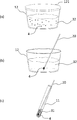
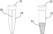
- FIG. 1 is a figure showing the mode of the fixing process which makes the magnetic particle 4 suspend in the liquid sample 32 in the liquid sample container 12, and fixes an object component to the magnetic particle 4.
- FIG. (B) is a figure showing a mode that the magnetic rod 20 is made to contact the liquid sample 32, and the magnetic particle 4 is attached to the magnetic rod 20 by magnetism.
- (C) is a figure showing a mode that the magnetic material 20 to which the magnetic particle 4 adhered is made to immerse in the liquid agent 31, and the liquid agent 31 is made to act on the object component fixed to the magnetic particle 4.
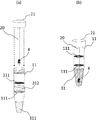
- FIG. It is a schematic diagram for demonstrating Embodiment 2 of the method of this invention.
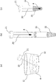
- FIG. 1 is a figure showing a mode that the magnetic rod 4 provided with the lid 21 is brought into contact with the liquid sample 32 in which the magnetic particles 4 are suspended, and the magnetic particles 4 are recovered.
- (B) is a figure showing a mode that the magnetic stick
- (C) is a figure showing the state which seals the opening of liquid medicine container 11 with lid 21, makes magnetic particles 4 adhering to magnetic stick 20 contact liquid medicine 31, and makes liquid medicine 31 act on object ingredient.
- 7 is a cross-sectional view showing a magnetic rod 20 provided with a lid 21 in Embodiment 2.
- FIG. It is a figure showing magnetic stick 20 provided with lid 21 in another embodiment.
- FIG. 10 depicts the test set of embodiment 2 in a pre-use condition.
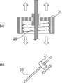
- FIG. 18 is a diagram illustrating an operation process in Embodiment 3.
- (A) is a figure showing a mode that the magnetic rod 20 to which the magnetic particle 4 adhered is inserted in the liquid agent storage container 11 in which the reagent 311 and the reagent 312 were separated and stored by the film material 111.
- the two film members 111 are broken by the magnetic rod 20, the opening of the liquid agent container 11 is closed by the lid 21, and the magnetic particles 4 attached to the magnetic rod 20 are mixed with the reagent 311 and the reagent 312.
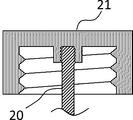
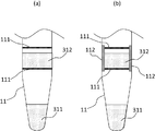
- FIG. 10 shows a cross-sectional view of the liquid agent storage container 11 in which the reagent 311 and the reagent 312 are separated and stored by the membrane material 111.
- FIG. (A) shows a cross-sectional view of the liquid agent storage container 11 of the third embodiment.
- (B) represents the cross-sectional view of the liquid agent storage container 11 in another embodiment.
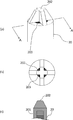
- FIG. 5 is a cross-sectional view of a tip portion of a magnetic rod 20.
- FIG. 2 is a view showing a tip portion of a magnetic rod 20.
- FIG. 16 is a diagram illustrating an operation process in Embodiment 4.
- (A) is a figure showing a mode that the magnetic stick
- the bag 13 is broken by the magnetic rod 20, the opening of the liquid agent container 11 is closed by the lid 21, and the magnetic particles 4 attached to the magnetic rod 20 are mixed with the reagent 311 and the reagent 312.
- It is a figure showing a mode that it makes a liquid agent 31 contact and makes a target component act.
- Embodiment 1 of the method of the present invention will be described with reference to FIG.
- the magnetic particles 4 are suspended in the liquid sample 32 (FIG. 1 (a)).
- liquid sample 32 to which the present invention can be applied is not particularly limited as long as it is a liquid containing a target component to be separated, isolated or detected.
- liquid samples include liquid samples of biological origin such as blood, sweat, and urine, environment-derived liquid samples such as river water, marine water, and suspensions of soil, and liquid samples of food origin. it can.
- the type of magnetic particles 4 is not particularly limited as long as it can be suspended in a liquid and can be obtained by magnetic collection means.
- commercially available products such as DYNABEADS (registered trademark) (Invitrogen), PureProteome (Merck Millipore), magnetic beads available from New England Biolabs, Mag Sepharose (GE Healthcare), and the like can be used.
- the target component is also not particularly limited, and can be set according to the purpose of the test.
- cells such as animal cells, plant cells and bacteria, biomolecules such as nucleic acids, proteins, saccharides and lipids, natural low molecules, synthetic low molecules, high molecular compounds, metals and the like can be specifically mentioned. .
- the magnetic particles 4 need to be capable of fixing the target component.
- the configuration that enables the target component to be fixed can be appropriately set according to the type of the target component.
- Magnetic particles 4 coated with a substance having direct or indirect binding ability can be used.
- the coating method of the magnetic particle 4 can be performed according to a conventional method. Alternatively, commercially available magnetic particles that have already been coated may be used.
- the method of suspending the magnetic particles 4 in the liquid sample 32 is not particularly limited. As shown to a figure (a), a mixed solution may be accommodated in the liquid sample container 12 sealed by the lid 121, and may be shaken, and you may stir by a stirrer.
- the form of the liquid sample container 12 is not limited to that shown in FIG. 1 (a), and various containers may be appropriately selected and used.
- the magnetic rod 20 is brought into contact with the liquid sample 32 in which the magnetic particles 4 are suspended, and the magnetic particles 4 are attached to the magnetic rod 20 by magnetism.
- the configuration of the magnetic rod 20 is not particularly limited, as long as the magnetic particles 4 recovered in an operation process described later can be brought into contact with the liquid agent 31.
- a magnetic rod 20 provided with a magnetic part having a magnetic property on the lower end side.
- the magnetic part can be composed of a permanent magnet such as an alnico magnet, a ferrite magnet, a neodymium magnet, or a samarium cobalt magnet.
- the magnetic rods 20 are pulled up from the liquid sample 32, and the magnetic particles 4 are recovered from the liquid sample 32. After the recovery, if necessary, the tip of the magnetic rod 20 may be immersed in a washing solution to wash the magnetic particles 4.
- the magnetic rod 20 is immersed in the liquid agent 31 contained in the liquid agent container 11, the magnetic particles 4 are brought into contact with the liquid agent 31, and the liquid agent 31 is allowed to act on the target component (FIG. 1 (c)).
- reaction includes chemical reactions that allow detection of the target component, as well as cell growth effects represented by the action of culture media on cells.
- the type of the liquid agent 31 and the mode of the action of the liquid agent 31 and the target component can be appropriately selected according to the type of the target component and the purpose of the test.
- the liquid agent 31 is a detection liquid that exhibits a detection response to the target component.
- the liquid preparation 31 is a culture medium.
- test tube is shown as a liquid agent storage container 11 in FIG.1 (c), the form is not specifically limited, According to the objective of a test, it can select suitably.
- the opening is covered with a thin film such as aluminum foil or a wrap as required, and the operation process is performed. May be
- the second embodiment of the present invention will be described with reference to FIGS.
- the magnetic rod 20 integrated with the lid 21 is used as the magnetic collecting means.
- the magnetic rod 20 is provided on the back side of the lid 21.
- the lid 21 is configured to be able to seal the opening of the liquid medicine container 11.
- the magnetic rod 20 in the second embodiment is fitted to the back surface of the lid 21, but the magnetic rod 20 and the lid 21 may be formed by one member, for example.
- the specific configuration in which the magnetic rod 20 is provided on the back surface side of the lid 21 is not limited to this.
- the magnetic rod 20 is penetrated through the through holes passing through the front and back of the lid 21 You may provide so that it may fit.
- the lid 21 can be configured to be slidable in the axial direction of the magnetic rod 20.
- the lid 21 is positioned on the upper end side of the magnetic rod 20, and in the action step, the lid 21 is slid toward the lower end of the magnetic rod 20 A method of sealing the opening of the container 11 can also be realized.
- the tester can operate the magnetic rod 20 while gripping the lid 21. Since the recovery process can be performed without directly touching the magnetic rod 20, the risk of contamination can be reduced.
- the magnetic rod 20 to which the magnetic particles 4 are attached is inserted from the opening of the liquid agent container 11 (FIG. 2 (b)), and the opening of the liquid agent container 11 is closed by the lid 21 (FIG. c)).
- the lid 21 is a screw cap, and the opening of the liquid medicine container 11 can be sealed by screwing the opening (FIG. 3).
- the lid 21 does not have to be a screw cap, and the form is not particularly limited as long as the opening of the liquid agent container 11 can be sealed.
- the magnetic particles 4 magnetically attached to the lower end of the magnetic rod 20 are contained in the liquid container 11. It will contact the liquid agent 31. At the same time, a sealed configuration is completed which prevents the liquid agent 31 from scattering out of the opening of the liquid agent container 11 in the action step. That is, in the second embodiment, the contact of the magnetic particles 4 with the liquid agent 31 and the construction of the scattering prevention structure of the liquid agent 31 are realized by a one-step operation of sealing the opening of the liquid agent container 11 with the lid 21. be able to. According to the second embodiment, it is possible to realize a test that is simple and quick, and has a low risk of contamination.
- the heated liquid agent 31 may evaporate and diffuse, and may be diffused from the liquid agent container 11 to the outside.
- the lid 21 since the opening of the liquid agent container 11 can be sealed by the lid 21, evaporation and diffusion of the liquid agent 31 due to heating can be prevented. That is, when the liquid agent 31 needs heating in order to act on the target component, the lid 21 seals the opening of the liquid agent container 11 so that the magnetic particles 4 can be transferred to the liquid agent 31 in one step. It is possible to realize the contact, and the scattering and evaporation diffusion preventing structure of the liquid agent 31.
- the second embodiment of the present invention It is preferable to apply.
- the magnetic rod 20 provided with the lid 21 and the liquid agent container 11 may be provided as a test set.
- the liquid agent 31 accommodated in the liquid agent container 11 may be prepared by the examiner at the time of use. From the viewpoint of realizing a simple and quick test, it is preferable to provide the liquid agent 31 in the state of containing the liquid agent in advance in the liquid agent storage container 11 (FIG. 5). In this case, the opening of the liquid medicine container 11 is preferably provided in a state of being sealed by the temporary lid 22 (FIG. 5).
- the magnetic rods 20 be packaged by any packaging means, since it is not preferable that the magnetic rods 20 contact the outside environment before use of the test set.
- packaging means include a protective container whose opening can be sealed by the lid 21 (FIG. 5). As shown in FIG. 5, it is preferable that the magnetic rod 20 be accommodated in the protective container 14 before use, and the lid 21 be provided in a state where the opening of the protective container 14 is sealed.
- the packaging means of the magnetic rod 20 before use is not limited to the form shown in FIG. 5, and may be an individual package or a collective package.
- the lid 21 is exposed to the external environment in the configuration shown in FIG. 5, the lid 21 may be packaged so as to protect not only the magnetic rod 20 but also the lid 21.
- the test set may include the magnetic rod 20 provided with the lid 21 and the liquid agent storage container 11.
- Liquid sample containers may also be provided together as an element of the test set.
- Embodiment 3 Hereinafter, the third embodiment of the present invention will be described with reference to FIGS. Of the items described in the description of the first and second embodiments, the items applicable to the third embodiment can also be applied to the third embodiment.
- two sheets of film material 111 for dividing the internal space into upper and lower portions are provided inside the liquid agent storage container 11 (FIGS. 6 and 7).
- the reagent 312 is stored in the space partitioned by the film material 111 and the wall surface of the liquid agent container 11, and the reagent 311 is stored in the bottom of the liquid agent container 11 (FIGS. 6 and 7).
- the liquid preparation 31 can be prepared by mixing the reagent 311 and the reagent 312. Since the liquid agent 31 after mixing may be a liquid, either of the reagent 311 and the reagent 312 may be solid.
- 6 and 7 disclose the configuration in which two sheets of the film material 111 are provided, but the configuration may be such that only one sheet of the film material 111 is provided. Further, three or more sheets of the film material 111 may be provided, and the liquid agent 31 may be divided into three or more types of reagents and accommodated in the liquid agent container 11.
- the material of the film material 111 is not particularly limited as long as it can be broken by the magnetic rod 20, and may be aluminum foil, paper, or resin.
- the film material 111 may be provided directly on the wall surface of the liquid agent container 11 (FIG. 7A), or may be provided by fitting the cylindrical member 112 with the film material 111 stretched inside the liquid agent container 11. It is good ( Figure 7 (b)).
- the film material 111 can be broken by the magnetic rod 20, the magnetic rod 20 with the magnetic particles 4 attached is inserted into the liquid agent container 11 (FIG. 6A), and the opening of the liquid agent container 11 is closed. If sealed at 21, the membrane material 111 is broken, and the reagent 312 stored thereon is leaked to the bottom of the liquid agent container 11 (FIG. 6 (b)). Then, it is mixed with the reagent 311 stored in the bottom of the liquid agent container 11 to prepare the liquid agent 31, and at the same time contact with the liquid agent 31 where the magnetic particles 4 attached to the magnetic rod 20 are prepared. The effect of 31 on the component of interest can be initiated.
- preparation of the liquid agent 31, contact of the magnetic particles 4 with the liquid agent 31, and prevention of scattering of the liquid agent 31 are performed in a one-step operation of closing the opening of the liquid agent container 11 with the lid 21.
- the construction of the structure can be realized.
- the present invention of Embodiment 3 is extremely effective in the case where the liquid agent 31 is a liquid agent that requires preparation at the time of use, in particular, a reaction solution used for a known detection reaction in which nonspecific reaction occurs if it is not prepared at the time of use. It is.
- the magnetic particle attached portion 203 to which the magnetic particles 4 are attached be separated from the fracture portion 202.
- the position of the magnetic particle attachment site 203 can be appropriately designed according to the installation mode of the magnetic portion 201 in the magnetic rod 20.
- the magnetic particle attached portion 203 is configured to be separated from the fracture portion 202 by providing the magnetic portion 201 having magnetism at a predetermined distance from the tip of the magnetic rod 20.
- the diameter of the magnetic portion 201 is made narrower than the portion other than the magnetic portion 201 of the magnetic rod 20, or the magnetic portion 201 is provided in the recess provided in the magnetic rod 20. Is also preferred. With such a configuration, it is possible to prevent the magnetic particles 4 from peeling off by coming into contact with the broken film material 111.
- the magnetic rod 20 may be formed of two bars, and the magnetic portion 201 may be interposed therebetween.
- a sharp slope may be provided at the tip of the magnetic rod 20, and the magnetic portion 201 may be embedded in a recess provided at the slope.
- FIGS. 8A to 8D illustrate the configuration in which the magnetic portion 201 having magnetism is provided at a predetermined distance from the tip of the magnetic rod 20.
- the magnetic particle attachment site 203 can be configured to be separated from the fracture site 202, the magnetic portion 201 does not necessarily have to be provided at a predetermined distance from the tip of the magnetic rod 20.
- the magnetic portion 201 is A configuration apart from the fracture site 202 can be realized.
- a configuration for separating the fracture site 202 and the magnetic particle adhesion site 203 a configuration in which the magnetic portion 201 is embedded in the inside of the magnetic rod 20 and a convex member provided with the fracture site 202 at the tip is mentioned (FIG. 9) .
- a convex member takes the form of the concave polygon frustum shape extended toward the front end direction from the base part of the magnetic rod 20.
- FIG. 9C due to the magnetism of the magnetic portion 201 embedded in the inside of the magnetic rod 20, the root portion of the convex member becomes the magnetic particle attached portion 203 (FIGS. 9A and 9B). .
- concave polygon frustum shape Although the thing of the form of concave polygon frustum shape was shown as a convex member in FIG. 9, the form should just have room which can form the magnetic particle adhesion part 203 in a root, and it may be a concave polygon pyramid.
- the liquid medicine container 11 contains a bag body 13 composed of a reagent 311 and a membrane material 111. Then, the reagent 312 is accommodated in the bag body 13.
- the film material 111 can be broken by the magnetic rod 20, the magnetic rod 20 with the magnetic particles 4 attached is inserted into the liquid agent container 11 (FIG. 10A), and the opening of the liquid agent container 11 is closed. If sealed at 21, the bag body 13 is broken, and the reagent 312 contained in the inside leaks to the outside (FIG. 10 (b)). Then, it is mixed with the reagent 311 stored in the bottom of the liquid agent container 11 to prepare the liquid agent 31, and at the same time contact with the liquid agent 31 where the magnetic particles 4 attached to the magnetic rod 20 are prepared. The effect of 31 on the component of interest can be initiated.
- the present invention can be applied to inspection instruments.
- liquid agent storage container 111 film material 12 liquid sample container 121 lid 13 bag 14 protective container 20 magnetic rod 201 magnetic portion 202 fracture site 203 magnetic particle adhesion site 21 lid 31 liquid agent 311 reagent 312 reagent 32 liquid sample 4 magnetic particle
Landscapes
- Health & Medical Sciences (AREA)
- Immunology (AREA)
- Life Sciences & Earth Sciences (AREA)
- Engineering & Computer Science (AREA)
- Molecular Biology (AREA)
- Biomedical Technology (AREA)
- Chemical & Material Sciences (AREA)
- Hematology (AREA)
- Urology & Nephrology (AREA)
- Biotechnology (AREA)
- Biochemistry (AREA)
- Cell Biology (AREA)
- Food Science & Technology (AREA)
- Medicinal Chemistry (AREA)
- Physics & Mathematics (AREA)
- Analytical Chemistry (AREA)
- Microbiology (AREA)
- General Health & Medical Sciences (AREA)
- General Physics & Mathematics (AREA)
- Pathology (AREA)
- Measuring Or Testing Involving Enzymes Or Micro-Organisms (AREA)
- Apparatus Associated With Microorganisms And Enzymes (AREA)
- Sampling And Sample Adjustment (AREA)
Abstract
磁性粒子を用いた試験の簡易性・迅速性を向上させる手段を提供することを課題とする。 回収した磁性粒子が付着した前記磁性収集手段を、前記対象成分に作用する液剤に接触させ、前記磁性収集手段に前記磁性粒子が付着した状態で、前記対象成分に前記液剤を作用させる作用工程を含む。
Description
本発明は磁性粒子を用いた試験器具に関する。
ある検体より対象成分を分離する手段として磁性粒子が広く用いられている。具体的には、磁性粒子により液体試料から遺伝子やバイオマーカーなどの対象成分を分離し、分離した対象成分を検出する方法(例えば特許文献1、2)、細菌などの対象成分を分離し、分離した対象成分を検出する方法(例えば、特許文献3)、あるいは磁性粒子を用いて所望の細胞を選別し、選別した細胞を培養する方法(例えば、特許文献4)などが広く知られている。
これら従来の方法においては、対象成分を補足した磁性粒子を回収するための手段として、磁気スタンド(例えば、特許文献5)や、電磁石などの磁界発生手段(例えば、特許文献6)などの外部磁場を用いることが通常であった。
磁性粒子を用いた対象成分の分離方法は、例えば遺伝子の検出方法などに広く用いられている。このような遺伝子の検出方法は、医療分野や農業分野あるいは飲食分野に一定のニーズがある。小規模病院や農家、あるいは飲食店においては、十分な研究設備と専門性に長けた検査者が望めない場合が多いため、簡易・迅速に実施可能な検査手法が求められている。
このような問題に鑑み、本発明の解決しようとする課題は、磁性粒子を用いた試験の簡易性・迅速性を向上させる手段を提供することにある。
このような問題に鑑み、本発明の解決しようとする課題は、磁性粒子を用いた試験の簡易性・迅速性を向上させる手段を提供することにある。
また、磁性粒子を使用する従来の方法では、外部磁場によって、磁性粒子を容器の壁面や底面に凝集させ、液体試料の上清を除去し、必要によって洗浄を行った後に、外部磁場を解除して磁性粒子を検出用の液などに再懸濁させる。つまり、上清を除去する工程において液体試料の移動を伴うため、液体試料が汚染性・感染性のあるものである場合には、該液体試料の飛散やエアロゾルの拡散などにより、コンタミネーション、検査者の感染のリスクがある。
このような問題に鑑み、本発明の好ましい形態では、磁性粒子を用いた試験におけるコンタミネーションや感染のリスクを低減する技術を提供することを課題とする。
このような問題に鑑み、本発明の好ましい形態では、磁性粒子を用いた試験におけるコンタミネーションや感染のリスクを低減する技術を提供することを課題とする。
上記課題を解決する本発明は、液体試料に磁性粒子を懸濁し、該磁性粒子に対象成分を固定する固定工程と、
前記液体試料に磁性収集手段を接触させ、前記対象成分が固定された前記磁性粒子を磁性により前記磁性収集手段に付着させた後に、前記磁性収集手段を前記液体試料から回収する回収工程と、
前記磁性粒子が付着した前記磁性収集手段を、前記対象成分に作用する液剤に接触させ、前記磁性収集手段に前記磁性粒子が付着した状態で、前記対象成分に前記液剤を作用させる作用工程を含むことを特徴とする方法である。
前記液体試料に磁性収集手段を接触させ、前記対象成分が固定された前記磁性粒子を磁性により前記磁性収集手段に付着させた後に、前記磁性収集手段を前記液体試料から回収する回収工程と、
前記磁性粒子が付着した前記磁性収集手段を、前記対象成分に作用する液剤に接触させ、前記磁性収集手段に前記磁性粒子が付着した状態で、前記対象成分に前記液剤を作用させる作用工程を含むことを特徴とする方法である。
本発明の方法では、液剤に磁性粒子を再懸濁せず、磁性収集手段に磁性粒子が付着した状態で対象成分に液剤を作用させるため、簡易性及び迅速性に優れる。
本発明の好ましい形態では、蓋体の裏面側に前記磁性収集手段が設けられており、
前記蓋体により密閉可能な開口を有する液剤収容容器に前記液剤が収容されており、
前記蓋体により前記液剤収容容器の開口を密閉し、前記蓋体の裏面側に設けられた前記磁性収集手段を前記液剤に接触させることで、前記作用工程を行うことを特徴とする。
前記蓋体により密閉可能な開口を有する液剤収容容器に前記液剤が収容されており、
前記蓋体により前記液剤収容容器の開口を密閉し、前記蓋体の裏面側に設けられた前記磁性収集手段を前記液剤に接触させることで、前記作用工程を行うことを特徴とする。
このような形態とすることで、蓋体により液剤収容容器を密閉するというワンステップの作業で、液剤へ磁性粒子を接触させ、液剤を対象成分に作用させる工程と、液剤又は液剤に溶解した対象成分が液剤収容容器から飛散することを防ぐ構成を構築する工程とを同時に行うことができる。
液剤が加温を必要とする場合、加温時に液剤が蒸発し液剤収容容器の外部に拡散することを防ぐ構成をとることが必要である。したがって、かかる形態の本発明は、前記液剤が、前記対象成分に作用するために加温を必要とするものである場合に特に有効である。
蓋体により液剤収容容器を密閉するというワンステップの作業で、液剤へ磁性粒子を接触させ、液剤を対象成分に作用させる工程と、液剤又は液剤に溶解した対象成分が液剤収容容器から飛散及び蒸発拡散することを防ぐ構成を構築する工程を同時に行うことができる。
蓋体により液剤収容容器を密閉するというワンステップの作業で、液剤へ磁性粒子を接触させ、液剤を対象成分に作用させる工程と、液剤又は液剤に溶解した対象成分が液剤収容容器から飛散及び蒸発拡散することを防ぐ構成を構築する工程を同時に行うことができる。
本発明の好ましい形態では、前記磁性収集手段が、少なくともその下端側に磁性を有する磁性棒であることを特徴とする。
磁性収集手段として磁性棒を採用することで、回収工程と作用工程を簡便に行うことができる。
磁性収集手段として磁性棒を採用することで、回収工程と作用工程を簡便に行うことができる。
本発明の好ましい形態では、前記液剤が少なくとも2種以上の試薬に分割して、開口を有する液剤収容容器内に収容されており、少なくとも1種の試薬は前記液剤収容容器の内部において、破断可能な膜材によって他の試薬と隔離されており、
前記磁性粒子が付着した前記磁性棒を開口より前記液剤収容容器内に挿入し、前記膜材を前記磁性棒により破断することで、前記液剤収容容器に収容された少なくとも2種以上の試薬を混合して前記液剤を調製し、かつ、前記磁性棒に付着した前記磁性粒子を該液剤に接触させることで前記作用工程を行うことを特徴とする。
前記磁性粒子が付着した前記磁性棒を開口より前記液剤収容容器内に挿入し、前記膜材を前記磁性棒により破断することで、前記液剤収容容器に収容された少なくとも2種以上の試薬を混合して前記液剤を調製し、かつ、前記磁性棒に付着した前記磁性粒子を該液剤に接触させることで前記作用工程を行うことを特徴とする。
かかる構成とすることにより、磁性棒で膜材を破断するというワンステップの作業で、試薬を混合することによって液剤を調製する工程と、液剤へ磁性粒子を接触させ、液剤を対象成分に作用させる工程を同時に行うことができる。
本発明の好ましい形態では、前記液剤収容容器の内部に、その内部空間を上下に仕切る前記膜材が少なくとも1枚設けられており、
少なくとも1種の前記試薬が前記液剤収容容器の底に貯留されており、別の少なくとも1種の前記試薬が前記膜材上に貯留されており、
前記膜材を前記磁性棒で破断することで、該膜材上に貯留されていた前記試薬を前記液剤収容容器の底に漏落させ、前記液剤収容容器の底に貯留されていた前記試薬と混合して前記液剤を調製し、かつ、前記磁性棒に付着した前記磁性粒子を該液剤に接触させることで前記作用工程を行うことを特徴とする。
少なくとも1種の前記試薬が前記液剤収容容器の底に貯留されており、別の少なくとも1種の前記試薬が前記膜材上に貯留されており、
前記膜材を前記磁性棒で破断することで、該膜材上に貯留されていた前記試薬を前記液剤収容容器の底に漏落させ、前記液剤収容容器の底に貯留されていた前記試薬と混合して前記液剤を調製し、かつ、前記磁性棒に付着した前記磁性粒子を該液剤に接触させることで前記作用工程を行うことを特徴とする。
かかる構成とすることにより、膜材の破断と試薬の混合による液剤の調製をより簡便に行うことができる。
また、本発明は液体試料から磁性粒子を用いて対象成分を回収し、該対象成分に液剤を作用させるための試験セットにも関する。
すなわち、本発明は、前記液剤を収容するための液剤収容容器と、
前記液剤収容容器の内部に挿入可能であり、前記磁性粒子を磁性により収集する磁性収集手段(但し磁性の解除手段を持たないものに限る)と、を備えることを特徴とする、試験セットである。
すなわち、本発明は、前記液剤を収容するための液剤収容容器と、
前記液剤収容容器の内部に挿入可能であり、前記磁性粒子を磁性により収集する磁性収集手段(但し磁性の解除手段を持たないものに限る)と、を備えることを特徴とする、試験セットである。
本発明の試験セットによれば、液剤に磁性粒子を再懸濁せずに、磁性収集手段に磁性粒子が付着した状態で対象成分に液剤を作用させるため、簡易・迅速な試験を実現できる。
本発明の好ましい形態では、前記液剤収容容器内に予め前記液剤が収容されていることを特徴とする。
かかる構成とすることによって、液剤を調製する手間が不要となり、より簡易性と迅速性を向上させることができる。
かかる構成とすることによって、液剤を調製する手間が不要となり、より簡易性と迅速性を向上させることができる。
本発明の好ましい形態では、前記磁性収集手段が、蓋体の裏面側に設けられた、少なくとも下端側に磁性を有する磁性棒であり、
前記液剤収容容器の開口を前記蓋体により密閉可能であり、
前記液剤収容容器の開口を前記蓋体により密閉したとき、前記磁性棒は前記液剤収容容器内に収容可能であることを特徴とする。
前記液剤収容容器の開口を前記蓋体により密閉可能であり、
前記液剤収容容器の開口を前記蓋体により密閉したとき、前記磁性棒は前記液剤収容容器内に収容可能であることを特徴とする。
このような形態とすることで、蓋体により液剤収容容器を密閉するというワンステップの作業で、液剤へ磁性粒子を接触させ、液剤を対象成分に作用させる工程と、液剤又は液剤に溶解した対象成分が液剤収容容器から飛散することを防ぐ構成を構築する工程と同時に行うことができる。
本発明の好ましい形態では、使用前の状態において、前記磁性収集手段が包装手段によって包装されており、かつ、前記液剤収容容器の開口が仮蓋で密閉されていることを特徴とする。
このように使用前の状態において磁性収集手段を包装しておくことによって、コンタミネーションを防ぐことができる。
このように使用前の状態において磁性収集手段を包装しておくことによって、コンタミネーションを防ぐことができる。
液剤が加温を必要とする場合、加温時に液剤が蒸発拡散することを防ぐ構成をとることが必要である。したがって、蓋体の裏面に磁性棒を備える構成を備える本発明の試験セットは、前記液剤が、前記対象成分に作用するために加温を必要とするものである場合に特に有効である。
蓋体により液剤収容容器を密閉するというワンステップの作業で、液剤へ磁性粒子を接触させ、液剤を対象成分に作用させる工程と、液剤又は液剤に溶解した対象成分が液剤収容容器から飛散及び蒸発拡散することを防ぐ構成を構築する工程を同時に行うことができる。
蓋体により液剤収容容器を密閉するというワンステップの作業で、液剤へ磁性粒子を接触させ、液剤を対象成分に作用させる工程と、液剤又は液剤に溶解した対象成分が液剤収容容器から飛散及び蒸発拡散することを防ぐ構成を構築する工程を同時に行うことができる。
本発明の好ましい形態では、前記液剤収容容器の内部に、その内部空間を上下に仕切る、前記磁性棒で破断可能な膜材が少なくとも1枚設けられており、
前記液剤が少なくとも2種以上の試薬に分割して前記液剤収容容器内に収容されており、少なくとも1種の前記試薬が前記液剤収容容器の底に貯留されており、別の少なくとも1種の前記試薬が前記膜材上に貯留されていることで、
前記膜材の破断により、該膜材上に貯留されていた前記試薬が前記液剤収容容器の底に漏落し、前記液剤収容容器の底に貯留されていた前記試薬と混合され、前記液剤が調製される構成をとることを特徴とする。
前記液剤が少なくとも2種以上の試薬に分割して前記液剤収容容器内に収容されており、少なくとも1種の前記試薬が前記液剤収容容器の底に貯留されており、別の少なくとも1種の前記試薬が前記膜材上に貯留されていることで、
前記膜材の破断により、該膜材上に貯留されていた前記試薬が前記液剤収容容器の底に漏落し、前記液剤収容容器の底に貯留されていた前記試薬と混合され、前記液剤が調製される構成をとることを特徴とする。
このような形態とすることで、蓋体により液剤収容容器を密閉するというワンステップの作業で、膜材を破断して試薬を混合し液剤を調製する工程と、液剤へ磁性粒子を接触させ、液剤を対象成分に作用させる工程と、液剤又は液剤に溶解した対象成分が液剤収容容器から飛散することを防ぐ構成を構築する工程を同時に行うことができる。
本発明によれば、磁性粒子を使用した試験の簡易性及び迅速性を向上させることができる。
また、本発明の好ましい形態によれば、コンタミネーションのリスクの低い試験技術を提供することができる。
また、本発明の好ましい形態によれば、コンタミネーションのリスクの低い試験技術を提供することができる。
<実施形態1>
以下、図1を参照しながら本発明の方法の実施形態1について説明を加える。
実施形態1においては、まず液体試料32中に磁性粒子4を懸濁する(図1(a)。
以下、図1を参照しながら本発明の方法の実施形態1について説明を加える。
実施形態1においては、まず液体試料32中に磁性粒子4を懸濁する(図1(a)。
本発明を適用可能な液体試料32の具体的な形態については特に限定されず、分離、単離又は検出の対象とする対象成分が含まれている液体であればよい。液体試料としては、例えば、血液、汗、尿等の生体由来の液体試料や、河川水、海洋水や土壌の懸濁液などの環境由来の液体試料、食品由来の液体試料等を挙げることができる。
磁性粒子4の種類は、液体中に懸濁可能であり、磁性収集手段により可能であるのであれば特に限定されない。例えば、DYNABEADS(登録商標)(インビトロジェン社)、PureProteome(メルクミリポア社)、ニューイングランドバイオラボ社より入手可能な磁気ビーズ、Mag Sepharose(GEヘルスケア社)など市販のものを用いることができる。
対象成分も特に限定されず、試験の目的に応じて設定することができる。例えば、動物細胞、植物細胞、細菌などの細胞類や、核酸、タンパク質、糖類、脂質などの生体分子、天然低分子、合成低分子、高分子化合物、金属等などを具体的に挙げることができる。
磁性粒子4は対象成分を固定可能なものである必要がある。対象成分を固定可能にする構成は、対象成分の種類によって適宜設定することができる。
例えば、抗体や抗体フラグメント、プロテインA、プロテインG、プロテインL、タグ配列を有するペプチド、ストレプトアビジン、ビオチン、核酸結合タンパク質、核酸、ヌクレオチド、アプタマー、PNA、酵素、その他有機化合物など、対象成分への直接的又は間接的な結合能を有する物質でコーティングされた磁性粒子4を用いることができる。
例えば、抗体や抗体フラグメント、プロテインA、プロテインG、プロテインL、タグ配列を有するペプチド、ストレプトアビジン、ビオチン、核酸結合タンパク質、核酸、ヌクレオチド、アプタマー、PNA、酵素、その他有機化合物など、対象成分への直接的又は間接的な結合能を有する物質でコーティングされた磁性粒子4を用いることができる。
磁性粒子4のコーティング方法は常法に従い行うことができる。また、すでにコーティングがなされている市販の磁性粒子を用いてもよい。
液体試料32に磁性粒子4を懸濁する方法は特に限定されない。図(a)に示すように蓋121で密閉された液体試料容器12中に混合液を収容して振とうしてもよいし、スターラーで攪拌してもよい。液体試料容器12の形態も図1(a)に示したものに限定されず、種々の容器を適宜選択して用いてよい。
実施形態1の方法においては、図1(b)に示すように、磁性棒20を磁性粒子4が懸濁された液体試料32に接触させ、磁性により磁性粒子4を磁性棒20に付着させる。
磁性棒20の構成は特に限定されず、後述する作用工程において回収した磁性粒子4を液剤31に接触可能な構成であればよい。
図1(b)に示すように、下端側に磁性を帯びた磁性部を備えた磁性棒20を用いることが好ましい。
磁性部はアルニコ磁石、フェライト磁石、ネオジム磁石、サマリウムコバルト磁石などの永久磁石により構成することができる。
図1(b)に示すように、下端側に磁性を帯びた磁性部を備えた磁性棒20を用いることが好ましい。
磁性部はアルニコ磁石、フェライト磁石、ネオジム磁石、サマリウムコバルト磁石などの永久磁石により構成することができる。
磁性粒子4の回収工程においては、効率よく磁性粒子4を回収するために、磁性棒20で液体試料32を攪拌することが好ましい。
磁性粒子4を磁性棒20に付着させたのち、磁性棒20を液体試料32より引き上げ、磁性粒子4を液体試料32から回収する。
回収後、必要に応じて、磁性棒20の先端を洗浄液に浸漬し、磁性粒子4を洗浄する洗浄工程を含んでもよい。
回収後、必要に応じて、磁性棒20の先端を洗浄液に浸漬し、磁性粒子4を洗浄する洗浄工程を含んでもよい。
回収工程の後、磁性棒20を液剤収容容器11に収容された液剤31に浸漬し、磁性粒子4を液剤31に接触させ、対象成分に液剤31を作用させる(図1(c))。
ここでいう「作用」には対象成分の検出を可能にするような化学反応のほか、細胞に対する培地の作用に代表されるような細胞育生作用も含まれる。
液剤31の種類及び液剤31と対象成分の作用の態様については、対象成分の種類や試験の目的に応じて適宜選択することができる。
例えば、試験の目的が対象成分の検出である場合には、液剤31は対象成分に対する検出反応を呈する検出液とする。
また、例えば試験の目的が細胞又は細菌の分離と培養である場合には、液剤31は培養用の培地とする。
例えば、試験の目的が対象成分の検出である場合には、液剤31は対象成分に対する検出反応を呈する検出液とする。
また、例えば試験の目的が細胞又は細菌の分離と培養である場合には、液剤31は培養用の培地とする。
図1(c)には、液剤収容容器11として試験管を示しているが、その形態は特に限定されず、試験の目的に応じて適宜選択することができる。
液剤収容容器11が図1(c)に示す試験管のような開口が開放しているものである場合には、アルミホイルやラップなどの薄膜で必要に応じて開口を覆って作用工程を行ってもよい。
<実施形態2>
以下、図2~5を参照しながら本発明の実施形態2について説明を加える。なお、実施形態1の説明で述べた事項のうち実施形態2にも妥当する事項については、実施形態2についても適用することができる。
実施形態2においては、磁性収集手段として蓋体21と一体となった磁性棒20を用いる。磁性棒20は蓋体21の裏面側に設けられている。この蓋体21は液剤収容容器11の開口を密閉することができるように構成されている。
以下、図2~5を参照しながら本発明の実施形態2について説明を加える。なお、実施形態1の説明で述べた事項のうち実施形態2にも妥当する事項については、実施形態2についても適用することができる。
実施形態2においては、磁性収集手段として蓋体21と一体となった磁性棒20を用いる。磁性棒20は蓋体21の裏面側に設けられている。この蓋体21は液剤収容容器11の開口を密閉することができるように構成されている。
図3に示すように、実施形態2における磁性棒20は蓋体21の裏面に嵌設されているが、例えば磁性棒20と蓋体21を一つの部材で構成してもよい。
蓋体21の裏面側に磁性棒20を設ける具体的な構成はこれに限られず、例えば、図4(a)に示すように蓋体21の表裏を通ずる貫通孔に磁性棒20を貫通させ、圧嵌するように設けてもよい。このような形態とすれば、図4(a)及び(b)に示すように、蓋体21を磁性棒20の軸方向に摺動可能に構成することができる。
この構成により、例えば、回収工程においては磁性棒20の上端側に蓋体21を位置させておき、作用工程においては蓋体21を磁性棒20の下端側に向けて摺動させて、液剤収容容器11の開口を密閉するような方法を実現することもできる。
この構成により、例えば、回収工程においては磁性棒20の上端側に蓋体21を位置させておき、作用工程においては蓋体21を磁性棒20の下端側に向けて摺動させて、液剤収容容器11の開口を密閉するような方法を実現することもできる。
回収工程においては、試験者が蓋体21を把持しながら磁性棒20を操作することができる。磁性棒20に直接触れることなく回収工程を行うことができるため、コンタミネーションのリスクを低減することができる。
回収工程の完了後、磁性粒子4が付着した磁性棒20を液剤収容容器11の開口から挿入し(図2(b))、蓋体21により液剤収容容器11の開口を密閉する(図2(c))。
実施形態2においては、蓋体21はスクリューキャップとなっており、開口と螺合させることにより液剤収容容器11の開口を密閉することができる(図3)。蓋体21はスクリューキャップとする必要はなく、液剤収容容器11の開口を密閉できれば、その形態は特に限定されない。
実施形態2においては、蓋体21はスクリューキャップとなっており、開口と螺合させることにより液剤収容容器11の開口を密閉することができる(図3)。蓋体21はスクリューキャップとする必要はなく、液剤収容容器11の開口を密閉できれば、その形態は特に限定されない。
磁性棒20を挿入し蓋体21によって液剤収容容器11の開口を密閉する動作に伴い、磁性棒20の下端側に磁性により付着していた磁性粒子4は、液剤収容容器11に収容されていた液剤31に接触することとなる。また、同時に作用工程において液剤31が液剤収容容器11の開口より外部に飛散することを防ぐ密閉構成が完成する。
つまり、実施形態2においては、蓋体21で液剤収容容器11の開口を密閉するというワンステップの動作で、磁性粒子4の液剤31への接触と、液剤31の飛散防止構造の構築を実現することができる。実施形態2によれば、簡易・迅速であり、かつ、コンタミネーションのリスクの低い試験を実現することができる。
つまり、実施形態2においては、蓋体21で液剤収容容器11の開口を密閉するというワンステップの動作で、磁性粒子4の液剤31への接触と、液剤31の飛散防止構造の構築を実現することができる。実施形態2によれば、簡易・迅速であり、かつ、コンタミネーションのリスクの低い試験を実現することができる。
液剤31が対象成分に作用するために加温が必要である場合には、加温された液剤31が蒸発拡散し、液剤収容容器11から外部に拡散してしまう恐れがある。本発明の実施形態2は、蓋体21により液剤収容容器11の開口を密閉できるため、加温による液剤31の蒸発拡散を防ぐことができる。
つまり、液剤31が対象成分に作用するために加温が必要である場合には、蓋体21で液剤収容容器11の開口を密閉するというワンステップの動作で、磁性粒子4の液剤31への接触と、液剤31の飛散及び蒸発拡散防止構造を実現することができる。
つまり、液剤31が対象成分に作用するために加温が必要である場合には、蓋体21で液剤収容容器11の開口を密閉するというワンステップの動作で、磁性粒子4の液剤31への接触と、液剤31の飛散及び蒸発拡散防止構造を実現することができる。
対象成分に作用する際の液剤31の温度が、30℃以上、好ましくは40℃以上、より好ましくは50℃以上のときに、液剤31の蒸発拡散防止の観点から、本発明の実施形態2を適用することが好ましい。
蓋体21を備えた磁性棒20と、液剤収容容器11を一組の試験セットとして提供することが好ましい。
液剤収容容器11に収容する液剤31は、試験者が用時調製する形態としてもよい。簡易・迅速な試験の実現の観点では、予め液剤収容容器11の内部に液剤31を収容した状態で提供することが好ましい(図5)。この場合、液剤収容容器11の開口は仮蓋22によって密閉した状態で提供することが好ましい(図5)。
液剤収容容器11に収容する液剤31は、試験者が用時調製する形態としてもよい。簡易・迅速な試験の実現の観点では、予め液剤収容容器11の内部に液剤31を収容した状態で提供することが好ましい(図5)。この場合、液剤収容容器11の開口は仮蓋22によって密閉した状態で提供することが好ましい(図5)。
また、試験セットの使用前において磁性棒20が外部環境にみだりに接触することは好ましくないことから、磁性棒20は何らかの包装手段によって包装されていることが好ましい。包装手段としては、蓋体21により開口を密閉可能な保護容器が挙げられる(図5)。図5に示すように、使用前においては磁性棒20が保護容器14に収容されており、かつ、蓋体21が保護容器14の開口を密閉している状態で提供されることが好ましい。
使用前における磁性棒20の包装手段は図5に示す形態に限られず、個別包装であっても集合包装であってもよい。図5に示す形態であれば蓋体21は外部環境に露出しているが、磁性棒20だけでなく蓋体21も保護するように包装してもよい。
試験セットとしては、蓋体21を備えた磁性棒20と、液剤収容容器11が含まれていればよいが、その他、磁性粒子4や該磁性粒子4を収容した容器、液体試料を入れるための液体試料容器も試験セットの要素としてまとめて提供する形態としてもよい。
<実施形態3>
以下、図6~9を参照しながら本発明の実施形態3について説明を加える。なお、実施形態1及び2の説明で述べた事項のうち実施形態3にも妥当する事項については、実施形態3についても適用することができる。
実施形態3においては、液剤収容容器11の内部に、その内部空間を上下に仕切る膜材111が2枚設けられている(図6及び7)。そして、膜材111と液剤収容容器11の壁面で区画されている空間には試薬312が貯留されており、液剤収容容器11の底には試薬311が貯留されている(図6及び7)。
以下、図6~9を参照しながら本発明の実施形態3について説明を加える。なお、実施形態1及び2の説明で述べた事項のうち実施形態3にも妥当する事項については、実施形態3についても適用することができる。
実施形態3においては、液剤収容容器11の内部に、その内部空間を上下に仕切る膜材111が2枚設けられている(図6及び7)。そして、膜材111と液剤収容容器11の壁面で区画されている空間には試薬312が貯留されており、液剤収容容器11の底には試薬311が貯留されている(図6及び7)。
試薬311と試薬312を混合することにより液剤31を調製することができる。混合後の液剤31が液体であればよいので、試薬311と試薬312の何れかが固体であってもよい。
図6及び7には、膜材111を2枚備えた構成を開示しているが、膜材111を1枚だけ備えた構成としてもよい。また、膜材111を3枚以上設け、液剤31を3種以上の試薬に分割して液剤収容容器11に収容する構成としてもよい。
膜材111の素材は、磁性棒20で破断可能であれば特に限定されず、アルミ箔、紙、樹脂であってもよい。
膜材111は液剤収容容器11の壁面に直接設けてもよいし(図7(a))、膜材111を張った円筒部材112を液剤収容容器11の内部に嵌合させることで設けてもよい(図7(b))。
膜材111は磁性棒20で破断可能であるため、磁性粒子4が付着した状態の磁性棒20を液剤収容容器11に挿入し(図6(a))、液剤収容容器11の開口を蓋体21で密閉すれば、膜材111は破断し、その上に貯留されていた試薬312は液剤収容容器11の底に漏落する(図6(b))。すると、液剤収容容器11の底に貯留されていた試薬311と混合し、液剤31が調製されると同時に、磁性棒20に付着していた磁性粒子4が調製された液剤31に接触し、液剤31による対象成分への作用を開始することができる。
すなわち、実施形態3においては、蓋体21で液剤収容容器11の開口を密閉するというワンステップの動作で、液剤31の調製と、磁性粒子4の液剤31への接触と、液剤31の飛散防止構造の構築を実現することができる。
液剤31が用時調製が必要な液剤、特に用時調製しなければ非特異的な反応が起こってしまう公知の検出反応に用いられる反応液である場合において、実施形態3の本発明は極めて有効である。
液剤31が用時調製が必要な液剤、特に用時調製しなければ非特異的な反応が起こってしまう公知の検出反応に用いられる反応液である場合において、実施形態3の本発明は極めて有効である。
実施形態3においては、磁性粒子4が付着した状態の磁性棒20により膜材111を破断する必要がある。磁性棒20による膜材111の破断は、具体的には磁性棒20の先端などの破断部位202で膜材111を押圧することによって実現されるが、仮に破断部位202に磁性粒子4が付着している場合には、膜材111との接触により磁性粒子4が剥離してしまう恐れがある。
磁性粒子4が剥離することを防止するため、図8(a)に示すように、磁性粒子4が付着する磁性粒子付着部位203は、破断部位202から離れていることが好ましい。磁性粒子付着部位203の位置は、磁性棒20における磁性部201の設置態様により適宜設計することができる。実施形態3においては、磁性を有する磁性部201を、磁性棒20の先端から所定距離をおいて設けることによって、磁性粒子付着部位203が破断部位202から離れるように構成されている。
磁性粒子4が剥離することを防止するため、図8(a)に示すように、磁性粒子4が付着する磁性粒子付着部位203は、破断部位202から離れていることが好ましい。磁性粒子付着部位203の位置は、磁性棒20における磁性部201の設置態様により適宜設計することができる。実施形態3においては、磁性を有する磁性部201を、磁性棒20の先端から所定距離をおいて設けることによって、磁性粒子付着部位203が破断部位202から離れるように構成されている。
また、図8(b)に示すように、磁性部201の径を磁性棒20の磁性部201以外の部分より狭くするか、或いは、磁性棒20に設けた凹部内部に磁性部201を設けることも好ましい。このような構成とすることにより、破断した膜材111に接触することで磁性粒子4が剥離することを防ぐことができる。
図8(c)に示すように、磁性棒20を2本の棒材により構成し、その間に磁性部201を挟設する構成としてもよい。
磁性棒20の先端に鋭利な傾斜を設け、その傾斜に設けられた凹部内部に磁性部201を埋設する構成としてもよい。このような構成とすることにより、膜材111の磁性棒20による破断が容易となり、かつ、膜材111への接触による磁性棒20からの磁性粒子4の剥離を防止することができる(図8(d))。
図8(a)~(d)では、磁性を有する磁性部201を、磁性棒20の先端から所定距離をおいて設けた構成を例示している。しかし、磁性粒子付着部位203が破断部位202から離れるように構成できれば、必ずしも磁性部201を磁性棒20の先端から所定距離をおいて設ける必要はない。
例えば、磁性棒20の先端を磁性部201で構成した場合であっても、磁性部201自身に凹部を設け、その凹部内に磁性粒子4が集積するようにすれば、磁性粒子付着部位203が破断部位202から離れた構成を実現できる。
例えば、磁性棒20の先端を磁性部201で構成した場合であっても、磁性部201自身に凹部を設け、その凹部内に磁性粒子4が集積するようにすれば、磁性粒子付着部位203が破断部位202から離れた構成を実現できる。
その他、破断部位202と磁性粒子付着部位203を離間させる構成としては、磁性棒20の内部に磁性部201を埋設し、先端に破断部位202を備える凸部材を設ける構成が挙げられる(図9)。
図9(a)に示すように、凸部材は、磁性棒20の基底部より先端方向に向かって延設された凹多角錐台状の形態をとる。図9(c)に示すように、磁性棒20の内部に埋設された磁性部201の磁性により、凸部材の根元部分が磁性粒子付着部位203となる(図9(a)、(b))。
図9(a)に示すように、凸部材は、磁性棒20の基底部より先端方向に向かって延設された凹多角錐台状の形態をとる。図9(c)に示すように、磁性棒20の内部に埋設された磁性部201の磁性により、凸部材の根元部分が磁性粒子付着部位203となる(図9(a)、(b))。
図9には凸部材として凹多角錐台状の形態のものを示したが、その形態は根元に磁性粒子付着部位203を形成可能な余地があればよく、凹多角錐であってもよい。
<実施形態4>
以下、図10を参照しながら本発明の実施形態4について説明を加える。なお、実施形態1~3の説明で述べた事項のうち実施形態4にも妥当する事項については、実施形態4についても適用することができる。
実施形態4においては、液剤収容容器11に試薬311と、膜材111で構成された袋体13が収容されている。そして、袋体13の中には試薬312が収容されている。
以下、図10を参照しながら本発明の実施形態4について説明を加える。なお、実施形態1~3の説明で述べた事項のうち実施形態4にも妥当する事項については、実施形態4についても適用することができる。
実施形態4においては、液剤収容容器11に試薬311と、膜材111で構成された袋体13が収容されている。そして、袋体13の中には試薬312が収容されている。
膜材111は磁性棒20で破断可能であるため、磁性粒子4が付着した状態の磁性棒20を液剤収容容器11に挿入し(図10(a))、液剤収容容器11の開口を蓋体21で密閉すれば、袋体13は破断し、その内部に収容されていた試薬312は外部に漏出する(図10(b))。すると、液剤収容容器11の底に貯留されていた試薬311と混合し、液剤31が調製されると同時に、磁性棒20に付着していた磁性粒子4が調製された液剤31に接触し、液剤31による対象成分への作用を開始することができる。
すなわち、実施形態4においては、実施形態3と同様に、蓋体21で液剤収容容器11の開口を密閉するというワンステップの動作で、液剤31の調製と、磁性粒子4の液剤31への接触と、液剤31の飛散防止構造の構築を実現することができる。
液剤31が用時調製が必要な液剤、特に液剤31が用時調製しなければ非特異的な反応が起こってしまう公知の検出反応に用いられる反応液である場合において、実施形態4の本発明は極めて有効である。
液剤31が用時調製が必要な液剤、特に液剤31が用時調製しなければ非特異的な反応が起こってしまう公知の検出反応に用いられる反応液である場合において、実施形態4の本発明は極めて有効である。
本発明は検査器具に応用することができる。
11 液剤収容容器
111 膜材
12 液体試料容器
121 蓋
13 袋体
14 保護容器
20 磁性棒
201 磁性部
202 破断部位
203 磁性粒子付着部位
21 蓋体
31 液剤
311 試薬
312 試薬
32 液体試料
4 磁性粒子
111 膜材
12 液体試料容器
121 蓋
13 袋体
14 保護容器
20 磁性棒
201 磁性部
202 破断部位
203 磁性粒子付着部位
21 蓋体
31 液剤
311 試薬
312 試薬
32 液体試料
4 磁性粒子
Claims (12)
- 液体試料に磁性粒子を懸濁し、該磁性粒子に対象成分を固定する固定工程と、
前記液体試料に磁性収集手段を接触させ、前記対象成分が固定された前記磁性粒子を磁性により前記磁性収集手段に付着させた後に、前記磁性収集手段を前記液体試料から回収する回収工程と、
前記磁性粒子が付着した前記磁性収集手段を、前記対象成分に作用する液剤に接触させ、前記磁性収集手段に前記磁性粒子が付着した状態で、前記対象成分に前記液剤を作用させる作用工程を含むことを特徴とする方法。 - 蓋体の裏面側に前記磁性収集手段が設けられており、
前記蓋体により密閉可能な開口を有する液剤収容容器に前記液剤が収容されており、
前記蓋体により前記液剤収容容器の開口を密閉し、前記蓋体の裏面側に設けられた前記磁性収集手段を前記液剤に接触させることで、前記作用工程を行うことを特徴とする、請求項1に記載の方法。 - 前記液剤が、前記対象成分に作用するために加温を必要とするものであることを特徴とする、請求項2に記載の方法。
- 前記磁性収集手段が、少なくともその下端側に磁性を有する磁性棒であることを特徴とする、請求項1~3の何れか一項に記載の方法。
- 前記液剤が少なくとも2種以上の試薬に分割して、開口を有する液剤収容容器内に収容されており、少なくとも1種の試薬は前記液剤収容容器の内部において、破断可能な膜材によって他の試薬と隔離されており、
前記磁性粒子が付着した前記磁性棒を開口より前記液剤収容容器内に挿入し、前記膜材を前記磁性棒により破断することで、前記液剤収容容器に収容された少なくとも2種以上の試薬を混合して前記液剤を調製し、かつ、前記磁性棒に付着した前記磁性粒子を該液剤に接触させることで前記作用工程を行うことを特徴とする、請求項4に記載の方法。 - 前記液剤収容容器の内部に、その内部空間を上下に仕切る前記膜材が少なくとも1枚設けられており、
少なくとも1種の前記試薬が前記液剤収容容器の底に貯留されており、別の少なくとも1種の前記試薬が前記膜材上に貯留されており、
前記膜材を前記磁性棒で破断することで、該膜材上に貯留されていた前記試薬を前記液剤収容容器の底に漏落させ、前記液剤収容容器の底に貯留されていた前記試薬と混合して前記液剤を調製し、かつ、前記磁性棒に付着した前記磁性粒子を該液剤に接触させることで前記作用工程を行うことを特徴とする、請求項5に記載の方法。 - 液体試料から磁性粒子を用いて対象成分を回収し、該対象成分に液剤を作用させるための試験セットであって、
前記液剤を収容するための液剤収容容器と、
前記液剤収容容器の内部に挿入可能であり、前記磁性粒子を磁性により収集する磁性収集手段(但し磁性の解除手段を持たないものに限る)と、を備えることを特徴とする、試験セット。 - 前記液剤収容容器内に予め前記液剤が収容されていることを特徴とする、請求項7に記載の試験セット。
- 前記磁性収集手段が、蓋体の裏面側に設けられた、少なくとも下端側に磁性を有する磁性棒であり、
前記液剤収容容器の開口を前記蓋体により密閉可能であり、
前記液剤収容容器の開口を前記蓋体により密閉したとき、前記磁性棒は前記液剤収容容器内に収容可能であることを特徴とする、請求項8に記載の試験セット。 - 使用前の状態において、前記磁性収集手段が包装手段によって包装されており、かつ、前記液剤収容容器の開口が仮蓋で密閉されていることを特徴とする、請求項9に記載の試験セット。
- 前記液剤が、前記対象成分に作用するために加温を必要とするものであることを特徴とする、請求項9又は10に記載の試験セット。
- 前記液剤収容容器の内部に、その内部空間を上下に仕切る、前記磁性棒で破断可能な膜材が少なくとも1枚設けられており、
前記液剤が少なくとも2種以上の試薬に分割して前記液剤収容容器内に収容されており、少なくとも1種の前記試薬が前記液剤収容容器の底に貯留されており、別の少なくとも1種の前記試薬が前記膜材上に貯留されていることで、
前記膜材の破断により、該膜材上に貯留されていた前記試薬が前記液剤収容容器の底に漏落し、前記液剤収容容器の底に貯留されていた前記試薬と混合され、前記液剤が調製される構成をとることを特徴とする、請求項9~11の何れか一項に記載の試験セット。
Priority Applications (4)
| Application Number | Priority Date | Filing Date | Title |
|---|---|---|---|
| US16/760,284 US20200256863A1 (en) | 2017-10-31 | 2018-10-30 | Magnetic particle collection method and test set |
| EP18873731.6A EP3705184A4 (en) | 2017-10-31 | 2018-10-30 | MAGNETIC PARTICLE COLLECTION PROCESS AND ANALYSIS SET |
| KR1020207011947A KR20200103626A (ko) | 2017-10-31 | 2018-10-30 | 자성 입자 수집 방법 및 시험 세트 |
| CN201880071299.6A CN111315489A (zh) | 2017-10-31 | 2018-10-30 | 磁性粒子收集方法及试验套装 |
Applications Claiming Priority (2)
| Application Number | Priority Date | Filing Date | Title |
|---|---|---|---|
| JP2017211095A JP6680742B2 (ja) | 2017-10-31 | 2017-10-31 | 磁性粒子収集方法及び試験セット |
| JP2017-211095 | 2017-10-31 |
Publications (1)
| Publication Number | Publication Date |
|---|---|
| WO2019088106A1 true WO2019088106A1 (ja) | 2019-05-09 |
Family
ID=66333497
Family Applications (1)
| Application Number | Title | Priority Date | Filing Date |
|---|---|---|---|
| PCT/JP2018/040348 WO2019088106A1 (ja) | 2017-10-31 | 2018-10-30 | 磁性粒子収集方法及び試験セット |
Country Status (6)
| Country | Link |
|---|---|
| US (1) | US20200256863A1 (ja) |
| EP (1) | EP3705184A4 (ja) |
| JP (1) | JP6680742B2 (ja) |
| KR (1) | KR20200103626A (ja) |
| CN (1) | CN111315489A (ja) |
| WO (1) | WO2019088106A1 (ja) |
Cited By (4)
| Publication number | Priority date | Publication date | Assignee | Title |
|---|---|---|---|---|
| CN115290416A (zh) * | 2022-09-26 | 2022-11-04 | 宁德厦钨新能源材料有限公司 | 磁性颗粒清洁度测试方法 |
| CN115992039A (zh) * | 2023-03-21 | 2023-04-21 | 深圳市美德瑞生物科技有限公司 | 一种下部磁吸自动核酸提取装置 |
| US11701668B1 (en) * | 2020-05-08 | 2023-07-18 | 10X Genomics, Inc. | Methods and devices for magnetic separation |
| US11946038B1 (en) | 2020-05-29 | 2024-04-02 | 10X Genomics, Inc. | Methods and systems including flow and magnetic modules |
Families Citing this family (1)
| Publication number | Priority date | Publication date | Assignee | Title |
|---|---|---|---|---|
| EP4206312A4 (en) * | 2020-08-31 | 2024-02-28 | Kitazato Corp | CAP OF BIOLOGICAL SAMPLE STORAGE TUBE, AND BIOLOGICAL SAMPLE STORAGE CONTAINER EQUIPPED WITH SAME |
Citations (12)
| Publication number | Priority date | Publication date | Assignee | Title |
|---|---|---|---|---|
| JPH1068731A (ja) * | 1994-06-16 | 1998-03-10 | Boehringer Mannheim Gmbh | 液体中の被検成分を磁気的に分離する方法 |
| JP2006502850A (ja) * | 2002-10-18 | 2006-01-26 | バイオ−ノーブル オーワイ | 磁気移動法、微子移動装置と反応装置ユニット |
| JP2009517067A (ja) * | 2005-12-02 | 2009-04-30 | バイオ−ノーブル オーワイ | 生物学的成分の濃縮ユニット及び濃縮方法 |
| JP2009284834A (ja) | 2008-05-29 | 2009-12-10 | Hitachi Ltd | 大規模並列核酸分析方法 |
| JP2010081915A (ja) | 2008-10-02 | 2010-04-15 | Hitachi Metals Ltd | 細胞回収用磁気スタンドおよび細胞回収用キット |
| JP2010151678A (ja) | 2008-12-25 | 2010-07-08 | Olympus Corp | 大腸癌の診断方法および大腸癌診断用キット |
| JP2013516179A (ja) * | 2009-12-30 | 2013-05-13 | スリーエム イノベイティブ プロパティズ カンパニー | 微小粒子を用いた生きた生物負荷の検出法 |
| JP2013523430A (ja) * | 2010-03-29 | 2013-06-17 | スネクマ | 磁気プラグに捕捉された磁性粒子を回収するための装置および方法 |
| JP2016144445A (ja) | 2015-01-28 | 2016-08-12 | ユニバーサル・バイオ・リサーチ株式会社 | 自動バクテリア等検出装置およびその方法 |
| JP2017075938A (ja) | 2015-10-15 | 2017-04-20 | 東芝メディカルシステムズ株式会社 | 検体検査装置 |
| JP2017100094A (ja) * | 2015-12-03 | 2017-06-08 | 智治 竹内 | 重金属分離システム |
| JP2017158585A (ja) | 2010-12-22 | 2017-09-14 | フェイト セラピューティクス,インコーポレイテッド | 単細胞選別のための細胞培養プラットホームおよびiPSCの再プログラミングの増強 |
Family Cites Families (15)
| Publication number | Priority date | Publication date | Assignee | Title |
|---|---|---|---|---|
| JP3794734B2 (ja) * | 1995-08-07 | 2006-07-12 | オリンパス株式会社 | 液体試料の分析検査方法 |
| JPH09304385A (ja) * | 1996-05-14 | 1997-11-28 | Shionogi & Co Ltd | 磁性粒子分離装置及び物質の分離方法 |
| JP2000140827A (ja) * | 1998-11-05 | 2000-05-23 | Kansai Shingijutsu Kenkyusho:Kk | 水中または高含水土壌中の物質の回収方法およびその方法に使用する吸着組成物 |
| US6649419B1 (en) * | 2000-11-28 | 2003-11-18 | Large Scale Proteomics Corp. | Method and apparatus for protein manipulation |
| JP2003093038A (ja) * | 2001-09-21 | 2003-04-02 | Juki Corp | ハイブリダイゼーション装置及びこれを用いたサンプル中の核酸検出方法 |
| FI20040159A0 (fi) * | 2003-10-20 | 2004-02-02 | Bio Mobile Oy | Magneettinen siirtomenetelmä, mikropartikkelien siirtolaite, ja reaktioyksikkö |
| WO2006079814A2 (en) * | 2005-01-26 | 2006-08-03 | Enigma Diagnostics Ltd | Method for carrying out a multi-step reaction, breakable container for storing reagents and method for transferring solid reagent using an electrostatically charged wand |
| EP2069041A4 (en) * | 2006-10-06 | 2013-04-24 | Promega Corp | APPARATUS AND METHOD FOR SEPARATING MAGNETIC PARTICLES FROM A SOLUTION |
| JP2010160532A (ja) | 2009-01-06 | 2010-07-22 | Oki Electric Ind Co Ltd | 券類処理装置、プログラム及び方法 |
| JP2012132877A (ja) * | 2010-12-24 | 2012-07-12 | Panasonic Corp | 検体捕集方法とそれを用いる検体捕集装置 |
| FI20115175A0 (fi) * | 2011-02-23 | 2011-02-23 | Helsinki Thermo Fisher Scient Oy | Partikkelien prosessointi |
| EP2854979B1 (en) * | 2012-05-31 | 2018-03-07 | Siemens Healthcare Diagnostics Inc. | Magnetic particle washing apparatus and method |
| KR20160144445A (ko) | 2014-04-11 | 2016-12-16 | 마이크로소프트 테크놀로지 라이센싱, 엘엘씨 | 확장가능한 애플리케이션 표시, 마일스톤, 및 스토리라인 |
| KR20170075938A (ko) | 2015-12-24 | 2017-07-04 | 도중헌 | 죽염 염지제 및 그 염지제를 사용하여 구이육을 제조하는 방법 |
| WO2017160980A1 (en) * | 2016-03-15 | 2017-09-21 | Abbott Laboratories | Sample processing devices, systems and methods |
-
2017
- 2017-10-31 JP JP2017211095A patent/JP6680742B2/ja not_active Expired - Fee Related
-
2018
- 2018-10-30 CN CN201880071299.6A patent/CN111315489A/zh active Pending
- 2018-10-30 WO PCT/JP2018/040348 patent/WO2019088106A1/ja unknown
- 2018-10-30 US US16/760,284 patent/US20200256863A1/en not_active Abandoned
- 2018-10-30 KR KR1020207011947A patent/KR20200103626A/ko unknown
- 2018-10-30 EP EP18873731.6A patent/EP3705184A4/en not_active Withdrawn
Patent Citations (12)
| Publication number | Priority date | Publication date | Assignee | Title |
|---|---|---|---|---|
| JPH1068731A (ja) * | 1994-06-16 | 1998-03-10 | Boehringer Mannheim Gmbh | 液体中の被検成分を磁気的に分離する方法 |
| JP2006502850A (ja) * | 2002-10-18 | 2006-01-26 | バイオ−ノーブル オーワイ | 磁気移動法、微子移動装置と反応装置ユニット |
| JP2009517067A (ja) * | 2005-12-02 | 2009-04-30 | バイオ−ノーブル オーワイ | 生物学的成分の濃縮ユニット及び濃縮方法 |
| JP2009284834A (ja) | 2008-05-29 | 2009-12-10 | Hitachi Ltd | 大規模並列核酸分析方法 |
| JP2010081915A (ja) | 2008-10-02 | 2010-04-15 | Hitachi Metals Ltd | 細胞回収用磁気スタンドおよび細胞回収用キット |
| JP2010151678A (ja) | 2008-12-25 | 2010-07-08 | Olympus Corp | 大腸癌の診断方法および大腸癌診断用キット |
| JP2013516179A (ja) * | 2009-12-30 | 2013-05-13 | スリーエム イノベイティブ プロパティズ カンパニー | 微小粒子を用いた生きた生物負荷の検出法 |
| JP2013523430A (ja) * | 2010-03-29 | 2013-06-17 | スネクマ | 磁気プラグに捕捉された磁性粒子を回収するための装置および方法 |
| JP2017158585A (ja) | 2010-12-22 | 2017-09-14 | フェイト セラピューティクス,インコーポレイテッド | 単細胞選別のための細胞培養プラットホームおよびiPSCの再プログラミングの増強 |
| JP2016144445A (ja) | 2015-01-28 | 2016-08-12 | ユニバーサル・バイオ・リサーチ株式会社 | 自動バクテリア等検出装置およびその方法 |
| JP2017075938A (ja) | 2015-10-15 | 2017-04-20 | 東芝メディカルシステムズ株式会社 | 検体検査装置 |
| JP2017100094A (ja) * | 2015-12-03 | 2017-06-08 | 智治 竹内 | 重金属分離システム |
Non-Patent Citations (1)
| Title |
|---|
| See also references of EP3705184A4 * |
Cited By (4)
| Publication number | Priority date | Publication date | Assignee | Title |
|---|---|---|---|---|
| US11701668B1 (en) * | 2020-05-08 | 2023-07-18 | 10X Genomics, Inc. | Methods and devices for magnetic separation |
| US11946038B1 (en) | 2020-05-29 | 2024-04-02 | 10X Genomics, Inc. | Methods and systems including flow and magnetic modules |
| CN115290416A (zh) * | 2022-09-26 | 2022-11-04 | 宁德厦钨新能源材料有限公司 | 磁性颗粒清洁度测试方法 |
| CN115992039A (zh) * | 2023-03-21 | 2023-04-21 | 深圳市美德瑞生物科技有限公司 | 一种下部磁吸自动核酸提取装置 |
Also Published As
| Publication number | Publication date |
|---|---|
| CN111315489A (zh) | 2020-06-19 |
| JP6680742B2 (ja) | 2020-04-15 |
| EP3705184A1 (en) | 2020-09-09 |
| KR20200103626A (ko) | 2020-09-02 |
| JP2019080549A (ja) | 2019-05-30 |
| US20200256863A1 (en) | 2020-08-13 |
| EP3705184A4 (en) | 2021-07-14 |
Similar Documents
| Publication | Publication Date | Title |
|---|---|---|
| WO2019088106A1 (ja) | 磁性粒子収集方法及び試験セット | |
| US9902949B2 (en) | Methods for universal target capture | |
| CN105709924B (zh) | 磁性体粒子操作用装置 | |
| US9517472B2 (en) | Device and method for processing target component in tube | |
| JP2021073445A (ja) | サンプル作成のための装置、システムおよび方法 | |
| CN106457196B (zh) | 磁性物质颗粒的操作方法和磁性物质颗粒操作用装置 | |
| US20230094539A1 (en) | Diagnostic device and system | |
| CN106999890B (zh) | 颗粒操作方法和颗粒操作用装置 | |
| JP2010508090A (ja) | 貫通可能な隔壁キャップ | |
| EP3524979A1 (fr) | Dispositif adapté pour recevoir un échantillon biologique | |
| JPH09304385A (ja) | 磁性粒子分離装置及び物質の分離方法 | |
| US20180224442A1 (en) | Device for operating magnetic particles | |
| JP6088651B2 (ja) | 粒子操作方法および粒子操作デバイス | |
| US20140272997A1 (en) | Sample Preparation Device and Methods of Use | |
| CN107206347B (zh) | 磁性体粒子操作用器件以及磁性体粒子的操作方法 | |
| JP7130937B2 (ja) | マルチウェルプレート用蓋部材及びマルチウェルプレート | |
| US20210129158A1 (en) | Magnetic particle operation device | |
| JP6611794B2 (ja) | サンプルの採集及び処理用のデバイス | |
| JP6750692B2 (ja) | 磁性体粒子操作用デバイス及び磁性体粒子操作用装置 | |
| EP3460077B1 (en) | Diagnostic device and system | |
| US20220128555A1 (en) | Apparatuses for performing rapid diagnostic tests | |
| JP6525301B2 (ja) | 分析用容器、それを用いたターゲット分析用具およびターゲット分析方法 | |
| EP4230149A1 (en) | Device for collecting a sample, a kit comprising such device and a method using such device or kit | |
| JP4490768B2 (ja) | バイオサンプル用容器 | |
| JPWO2018016127A1 (ja) | ターゲット分析キットおよびターゲット分析方法 |
Legal Events
| Date | Code | Title | Description |
|---|---|---|---|
| 121 | Ep: the epo has been informed by wipo that ep was designated in this application |
Ref document number: 18873731 Country of ref document: EP Kind code of ref document: A1 |
|
| NENP | Non-entry into the national phase |
Ref country code: DE |
|
| ENP | Entry into the national phase |
Ref document number: 2018873731 Country of ref document: EP Effective date: 20200602 |