WO2019064875A1 - 制御対象車両設定装置、制御対象車両設定システムおよび制御対象車両設定方法 - Google Patents
制御対象車両設定装置、制御対象車両設定システムおよび制御対象車両設定方法 Download PDFInfo
- Publication number
- WO2019064875A1 WO2019064875A1 PCT/JP2018/028242 JP2018028242W WO2019064875A1 WO 2019064875 A1 WO2019064875 A1 WO 2019064875A1 JP 2018028242 W JP2018028242 W JP 2018028242W WO 2019064875 A1 WO2019064875 A1 WO 2019064875A1
- Authority
- WO
- WIPO (PCT)
- Prior art keywords
- vehicle
- control target
- target vehicle
- control
- setting
- Prior art date
Links
- 238000000034 method Methods 0.000 title claims description 31
- 238000001514 detection method Methods 0.000 claims abstract description 65
- 230000010354 integration Effects 0.000 claims abstract description 5
- 230000008859 change Effects 0.000 claims description 15
- 230000001629 suppression Effects 0.000 claims description 7
- 230000004927 fusion Effects 0.000 description 24
- 230000008569 process Effects 0.000 description 22
- 230000006399 behavior Effects 0.000 description 7
- 238000002485 combustion reaction Methods 0.000 description 6
- 238000007499 fusion processing Methods 0.000 description 5
- 239000012530 fluid Substances 0.000 description 4
- 230000007246 mechanism Effects 0.000 description 4
- 230000001133 acceleration Effects 0.000 description 3
- 238000000605 extraction Methods 0.000 description 3
- 239000000446 fuel Substances 0.000 description 3
- 238000002347 injection Methods 0.000 description 3
- 239000007924 injection Substances 0.000 description 3
- 238000000926 separation method Methods 0.000 description 3
- 238000013459 approach Methods 0.000 description 2
- 238000002038 chemiluminescence detection Methods 0.000 description 2
- 230000007423 decrease Effects 0.000 description 2
- 238000005516 engineering process Methods 0.000 description 2
- 230000006870 function Effects 0.000 description 2
- 238000003384 imaging method Methods 0.000 description 2
- VBICKXHEKHSIBG-UHFFFAOYSA-N 1-monostearoylglycerol Chemical compound CCCCCCCCCCCCCCCCCC(=O)OCC(O)CO VBICKXHEKHSIBG-UHFFFAOYSA-N 0.000 description 1
- DCXXMTOCNZCJGO-UHFFFAOYSA-N Glycerol trioctadecanoate Natural products CCCCCCCCCCCCCCCCCC(=O)OCC(OC(=O)CCCCCCCCCCCCCCCCC)COC(=O)CCCCCCCCCCCCCCCCC DCXXMTOCNZCJGO-UHFFFAOYSA-N 0.000 description 1
- 230000003044 adaptive effect Effects 0.000 description 1
- 230000008901 benefit Effects 0.000 description 1
- 238000013016 damping Methods 0.000 description 1
- 238000010586 diagram Methods 0.000 description 1
- 230000000694 effects Effects 0.000 description 1
- 230000002452 interceptive effect Effects 0.000 description 1
- 230000004048 modification Effects 0.000 description 1
- 238000012986 modification Methods 0.000 description 1
Images


Classifications
-
- B—PERFORMING OPERATIONS; TRANSPORTING
- B60—VEHICLES IN GENERAL
- B60W—CONJOINT CONTROL OF VEHICLE SUB-UNITS OF DIFFERENT TYPE OR DIFFERENT FUNCTION; CONTROL SYSTEMS SPECIALLY ADAPTED FOR HYBRID VEHICLES; ROAD VEHICLE DRIVE CONTROL SYSTEMS FOR PURPOSES NOT RELATED TO THE CONTROL OF A PARTICULAR SUB-UNIT
- B60W30/00—Purposes of road vehicle drive control systems not related to the control of a particular sub-unit, e.g. of systems using conjoint control of vehicle sub-units
- B60W30/14—Adaptive cruise control
- B60W30/16—Control of distance between vehicles, e.g. keeping a distance to preceding vehicle
- B60W30/162—Speed limiting therefor
-
- B—PERFORMING OPERATIONS; TRANSPORTING
- B60—VEHICLES IN GENERAL
- B60K—ARRANGEMENT OR MOUNTING OF PROPULSION UNITS OR OF TRANSMISSIONS IN VEHICLES; ARRANGEMENT OR MOUNTING OF PLURAL DIVERSE PRIME-MOVERS IN VEHICLES; AUXILIARY DRIVES FOR VEHICLES; INSTRUMENTATION OR DASHBOARDS FOR VEHICLES; ARRANGEMENTS IN CONNECTION WITH COOLING, AIR INTAKE, GAS EXHAUST OR FUEL SUPPLY OF PROPULSION UNITS IN VEHICLES
- B60K31/00—Vehicle fittings, acting on a single sub-unit only, for automatically controlling vehicle speed, i.e. preventing speed from exceeding an arbitrarily established velocity or maintaining speed at a particular velocity, as selected by the vehicle operator
- B60K31/0008—Vehicle fittings, acting on a single sub-unit only, for automatically controlling vehicle speed, i.e. preventing speed from exceeding an arbitrarily established velocity or maintaining speed at a particular velocity, as selected by the vehicle operator including means for detecting potential obstacles in vehicle path
-
- G—PHYSICS
- G08—SIGNALLING
- G08G—TRAFFIC CONTROL SYSTEMS
- G08G1/00—Traffic control systems for road vehicles
- G08G1/16—Anti-collision systems
-
- B—PERFORMING OPERATIONS; TRANSPORTING
- B60—VEHICLES IN GENERAL
- B60K—ARRANGEMENT OR MOUNTING OF PROPULSION UNITS OR OF TRANSMISSIONS IN VEHICLES; ARRANGEMENT OR MOUNTING OF PLURAL DIVERSE PRIME-MOVERS IN VEHICLES; AUXILIARY DRIVES FOR VEHICLES; INSTRUMENTATION OR DASHBOARDS FOR VEHICLES; ARRANGEMENTS IN CONNECTION WITH COOLING, AIR INTAKE, GAS EXHAUST OR FUEL SUPPLY OF PROPULSION UNITS IN VEHICLES
- B60K31/00—Vehicle fittings, acting on a single sub-unit only, for automatically controlling vehicle speed, i.e. preventing speed from exceeding an arbitrarily established velocity or maintaining speed at a particular velocity, as selected by the vehicle operator
- B60K31/0008—Vehicle fittings, acting on a single sub-unit only, for automatically controlling vehicle speed, i.e. preventing speed from exceeding an arbitrarily established velocity or maintaining speed at a particular velocity, as selected by the vehicle operator including means for detecting potential obstacles in vehicle path
- B60K2031/0016—Identification of obstacles; Selection of a target vehicle
-
- B—PERFORMING OPERATIONS; TRANSPORTING
- B60—VEHICLES IN GENERAL
- B60K—ARRANGEMENT OR MOUNTING OF PROPULSION UNITS OR OF TRANSMISSIONS IN VEHICLES; ARRANGEMENT OR MOUNTING OF PLURAL DIVERSE PRIME-MOVERS IN VEHICLES; AUXILIARY DRIVES FOR VEHICLES; INSTRUMENTATION OR DASHBOARDS FOR VEHICLES; ARRANGEMENTS IN CONNECTION WITH COOLING, AIR INTAKE, GAS EXHAUST OR FUEL SUPPLY OF PROPULSION UNITS IN VEHICLES
- B60K31/00—Vehicle fittings, acting on a single sub-unit only, for automatically controlling vehicle speed, i.e. preventing speed from exceeding an arbitrarily established velocity or maintaining speed at a particular velocity, as selected by the vehicle operator
- B60K31/0008—Vehicle fittings, acting on a single sub-unit only, for automatically controlling vehicle speed, i.e. preventing speed from exceeding an arbitrarily established velocity or maintaining speed at a particular velocity, as selected by the vehicle operator including means for detecting potential obstacles in vehicle path
- B60K2031/0025—Detecting position of target vehicle, e.g. vehicle driving ahead from host vehicle
-
- B—PERFORMING OPERATIONS; TRANSPORTING
- B60—VEHICLES IN GENERAL
- B60K—ARRANGEMENT OR MOUNTING OF PROPULSION UNITS OR OF TRANSMISSIONS IN VEHICLES; ARRANGEMENT OR MOUNTING OF PLURAL DIVERSE PRIME-MOVERS IN VEHICLES; AUXILIARY DRIVES FOR VEHICLES; INSTRUMENTATION OR DASHBOARDS FOR VEHICLES; ARRANGEMENTS IN CONNECTION WITH COOLING, AIR INTAKE, GAS EXHAUST OR FUEL SUPPLY OF PROPULSION UNITS IN VEHICLES
- B60K31/00—Vehicle fittings, acting on a single sub-unit only, for automatically controlling vehicle speed, i.e. preventing speed from exceeding an arbitrarily established velocity or maintaining speed at a particular velocity, as selected by the vehicle operator
- B60K31/0008—Vehicle fittings, acting on a single sub-unit only, for automatically controlling vehicle speed, i.e. preventing speed from exceeding an arbitrarily established velocity or maintaining speed at a particular velocity, as selected by the vehicle operator including means for detecting potential obstacles in vehicle path
- B60K2031/0033—Detecting longitudinal speed or acceleration of target vehicle
-
- B—PERFORMING OPERATIONS; TRANSPORTING
- B60—VEHICLES IN GENERAL
- B60K—ARRANGEMENT OR MOUNTING OF PROPULSION UNITS OR OF TRANSMISSIONS IN VEHICLES; ARRANGEMENT OR MOUNTING OF PLURAL DIVERSE PRIME-MOVERS IN VEHICLES; AUXILIARY DRIVES FOR VEHICLES; INSTRUMENTATION OR DASHBOARDS FOR VEHICLES; ARRANGEMENTS IN CONNECTION WITH COOLING, AIR INTAKE, GAS EXHAUST OR FUEL SUPPLY OF PROPULSION UNITS IN VEHICLES
- B60K31/00—Vehicle fittings, acting on a single sub-unit only, for automatically controlling vehicle speed, i.e. preventing speed from exceeding an arbitrarily established velocity or maintaining speed at a particular velocity, as selected by the vehicle operator
- B60K31/0008—Vehicle fittings, acting on a single sub-unit only, for automatically controlling vehicle speed, i.e. preventing speed from exceeding an arbitrarily established velocity or maintaining speed at a particular velocity, as selected by the vehicle operator including means for detecting potential obstacles in vehicle path
- B60K2031/0041—Detecting lateral speed of target vehicle
-
- B—PERFORMING OPERATIONS; TRANSPORTING
- B60—VEHICLES IN GENERAL
- B60W—CONJOINT CONTROL OF VEHICLE SUB-UNITS OF DIFFERENT TYPE OR DIFFERENT FUNCTION; CONTROL SYSTEMS SPECIALLY ADAPTED FOR HYBRID VEHICLES; ROAD VEHICLE DRIVE CONTROL SYSTEMS FOR PURPOSES NOT RELATED TO THE CONTROL OF A PARTICULAR SUB-UNIT
- B60W2552/00—Input parameters relating to infrastructure
- B60W2552/53—Road markings, e.g. lane marker or crosswalk
-
- B—PERFORMING OPERATIONS; TRANSPORTING
- B60—VEHICLES IN GENERAL
- B60W—CONJOINT CONTROL OF VEHICLE SUB-UNITS OF DIFFERENT TYPE OR DIFFERENT FUNCTION; CONTROL SYSTEMS SPECIALLY ADAPTED FOR HYBRID VEHICLES; ROAD VEHICLE DRIVE CONTROL SYSTEMS FOR PURPOSES NOT RELATED TO THE CONTROL OF A PARTICULAR SUB-UNIT
- B60W2554/00—Input parameters relating to objects
- B60W2554/80—Spatial relation or speed relative to objects
- B60W2554/801—Lateral distance
-
- B—PERFORMING OPERATIONS; TRANSPORTING
- B60—VEHICLES IN GENERAL
- B60W—CONJOINT CONTROL OF VEHICLE SUB-UNITS OF DIFFERENT TYPE OR DIFFERENT FUNCTION; CONTROL SYSTEMS SPECIALLY ADAPTED FOR HYBRID VEHICLES; ROAD VEHICLE DRIVE CONTROL SYSTEMS FOR PURPOSES NOT RELATED TO THE CONTROL OF A PARTICULAR SUB-UNIT
- B60W2554/00—Input parameters relating to objects
- B60W2554/80—Spatial relation or speed relative to objects
- B60W2554/806—Relative heading
-
- B—PERFORMING OPERATIONS; TRANSPORTING
- B60—VEHICLES IN GENERAL
- B60W—CONJOINT CONTROL OF VEHICLE SUB-UNITS OF DIFFERENT TYPE OR DIFFERENT FUNCTION; CONTROL SYSTEMS SPECIALLY ADAPTED FOR HYBRID VEHICLES; ROAD VEHICLE DRIVE CONTROL SYSTEMS FOR PURPOSES NOT RELATED TO THE CONTROL OF A PARTICULAR SUB-UNIT
- B60W2556/00—Input parameters relating to data
- B60W2556/10—Historical data
Definitions
- the present disclosure relates to a technique for setting a control target vehicle to be subjected to driving support control.
- a driving support control technology for supporting the driving of a host vehicle with respect to a front target using detection signals from target detectors such as a camera and a radar.
- target detectors such as a camera and a radar.
- it is required to appropriately set a control target vehicle to be a target of the driving support control from the front object.
- a technique for appropriately setting a front object existing on the same lane as the host vehicle as a control target vehicle that is, a preceding vehicle (for example, JP-A-8-279088). Issue).
- the front target object is not present on the traveling track of the own vehicle, it is uniformly set as the control target vehicle without considering the stationary vehicle having a low possibility of movement and the moving vehicle having the movement history or moving. Then, the frequency of execution of the driving support control becomes high, and the smooth driving of the host vehicle may be hindered, and the driver may be given an impression of excessive driving support control.
- a first aspect provides a control target vehicle setting device that sets a control target vehicle to be a target of driving support control.
- the control target vehicle setting device includes a detection signal acquisition unit capable of acquiring a first detection signal indicating an object by an image and a second detection signal indicating an object by a reflection point; A movement history indicating that the object is detected as a moving object is not associated, and an integration history indicating that the vehicle is determined by integrating and using the first detection signal and the second detection signal When the movement history is associated as the selection threshold of the first determination parameter that determines whether or not to set the vehicle to be controlled if the vehicle is associated with the front target object, the vehicle to be controlled is And a setting control unit that determines whether or not to set the front target object to the control target vehicle using a selection threshold that is hard to be selected.
- setting of the control target vehicle can be appropriately performed depending on whether the front target object is a stationary vehicle or a mobile vehicle.
- a second aspect provides a control target vehicle setting method for setting a control target vehicle to be a target of driving support control.
- the first detection signal indicating the object by the image and the second detection signal indicating the object by the reflection point are acquired and moved to the front object
- the movement history indicating that it is detected as an object is not associated, and the integrated history indicating that the vehicle is determined by integrating and using the first detection signal and the second detection signal is the front target
- the setting of the control target vehicle can be appropriately performed according to whether the front target object is a stationary vehicle or a moving vehicle.
- the present disclosure can also be realized as a control target vehicle setting program or a computer readable recording medium for recording the program.
- FIG. 1 is an explanatory view showing a vehicle equipped with the control target vehicle setting device according to the first embodiment
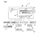
- FIG. 2 is a block diagram showing a functional configuration of a control device included in the control target vehicle setting device according to the first embodiment
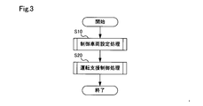
- FIG. 3 is a flowchart showing a process flow of control target vehicle setting processing and driving support control processing executed by the control target vehicle setting device according to the first embodiment
- FIG. 4 is a flow chart showing a processing flow of control target vehicle setting processing as the first embodiment
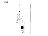
- FIG. 5 is an explanatory view showing the relationship between the host vehicle and the front object for explaining the relative lateral distance which is the first determination parameter
- FIG. 1 is an explanatory view showing a vehicle equipped with the control target vehicle setting device according to the first embodiment
- FIG. 2 is a block diagram showing a functional configuration of a control device included in the control target vehicle setting device according to the first embodiment
- FIG. 3 is a flowchart showing a process flow of control target vehicle setting processing and driving support control processing executed by the control target vehicle setting
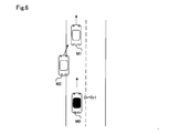
- FIG. 6 is an explanatory view showing the relationship between the host vehicle and the front object when the moving vehicle threshold is set as the selection threshold of the first determination parameter
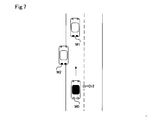
- FIG. 7 is an explanatory view showing the relationship between the host vehicle and the front target when the stationary vehicle threshold is set as the selection threshold of the first determination parameter
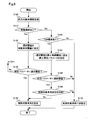
- FIG. 8 is a flowchart showing a processing flow of control target vehicle setting processing according to the second embodiment
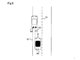
- FIG. 9 is an explanatory view showing the relationship between the host vehicle and the front object for explaining the overlap parameter which is an additional parameter
- FIG. 10 is an explanatory view showing the relationship between the host vehicle and the front object for explaining an extra parameter which is an additional parameter
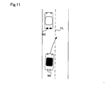
- FIG. 11 is an explanatory view showing the relationship between the host vehicle and the front object in the case of suppressing the setting of the control target vehicle
- FIG. 12 is an explanatory view showing the relationship between the host vehicle and the front object in the case where the setting of the control target vehicle is not suppressed
- FIG. 13 is an explanatory view showing the relationship between the host vehicle and the front target in the case where the setting of the control target vehicle is not suppressed
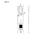
- FIG. 14 is an explanatory view showing the relationship between the host vehicle and the front target in the case of suppressing the setting of the control target vehicle during the execution of the driving support control process
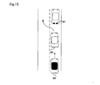
- FIG. 15 is an explanatory view showing a relationship between the host vehicle and the front target when setting of the vehicle to be controlled is not suppressed during execution of the driving support control process.
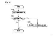
- FIG. 16 is a flowchart showing a processing flow of driving support control processing according to the third embodiment.
- the collision control target vehicle setting device, the control target vehicle setting system, and the control target vehicle setting method according to the present disclosure will be described below based on some embodiments.
- the control target vehicle setting device 10 As shown in FIG. 1, the control target vehicle setting device 10 according to the first embodiment is mounted on a vehicle 500 and used.
- the control target vehicle setting device 10 only needs to include at least the control device 100.
- the control target vehicle setting system includes the radar ECU 21, the camera ECU 22, the yaw rate sensor 23, the wheel speed sensor 24, and the control target vehicle setting device 10.
- a rotation angle sensor 25, a throttle drive device 31 and a braking assistance device 32 are provided.
- the vehicle 500 includes an internal combustion engine ICE, wheels 501, a braking device 502, a braking line 503, a steering wheel 504, a windshield 510, and a front bumper 520.
- the radar ECU 21 is connected to a millimeter wave radar 211 that emits radio waves and detects a reflected wave from an object, and uses a reflected wave acquired by the millimeter wave radar 211 to represent a detection signal representing the object by a reflection point. Generate and output.
- the camera ECU 22 is connected to the front camera 221, and generates and outputs a detection signal indicating the object by the image using the image acquired by the front camera 221 and the shape pattern of the object prepared in advance. .
- Each ECU is a microprocessor including an operation unit, a storage unit, and an input / output unit.
- the radar ECU 21 and the millimeter wave radar 211 correspond to a first detection unit
- the camera ECU 22 and the front camera 221 correspond to a second detection unit.
- a detector for detecting a reflected wave in addition to the millimeter wave radar 211, a lidar (LIDAR: laser radar) or an ultrasonic wave detector for emitting a sound wave and detecting the reflected wave may be used.
- a stereo camera or a multi-camera configured by two or more cameras may be used.
- the internal combustion engine ICE is provided with a throttle drive device 31 that drives a slot valve for adjusting the amount of intake air to control the output of the internal combustion engine ICE.
- a fuel injection device drive device for controlling the fuel injection amount by the fuel injection device may be used instead of the throttle valve drive device 31.
- a braking device 502 is provided for each wheel 501. Each braking device 502 realizes the braking of each wheel 501 by the brake fluid pressure supplied via the braking line 503 according to the driver's brake pedal operation.
- the brake line 503 includes a brake piston and a brake fluid line that derives a brake fluid pressure according to the brake pedal operation.
- the braking assistance device 32 is provided on the braking line 503, and hydraulic control can be performed independently of the operation of the braking pedal, whereby the braking assistance is realized.
- the brake line 503 may be replaced with a brake fluid line, and may be a control signal line, and may be configured to operate an actuator provided in each braking device 502.
- the steering wheel 504 is connected to the front wheel 501 via a steering mechanism 505 including a steering rod.
- Constant speed traveling / inter-vehicle distance control processing for causing the host vehicle to travel at a set vehicle speed while maintaining the inter-vehicle distance between the preceding vehicle and the host vehicle at a constant distance by the throttle drive device 31 and the braking assistance device 32, ie, adaptive -Cruise control (ACC) is realized as driving support control.
- the driving assistance also includes steering assistance for steering the steering mechanism (not shown) and the steering mechanism including the steering rod independently of the operation of the steering wheel by the driver, and these operations correspond to the braking assistance device. It can be controlled by a driving support device that includes the functions of
- the control device 100 includes a central processing unit (CPU) 101, a memory 102, an input / output interface 103, and a bus 104.
- the CPU 101, the memory 102, and the input / output interface 103 are bi-directionally connected via a bus.
- the memory 102 stores a control target vehicle setting program P1 for setting a control target vehicle to be a target of the driving support control and a driving support program P2 for executing the driving support control in a non-volatile and read-only manner, for example It includes a ROM and a memory that can be read and written by the CPU 101, such as a RAM.
- the memory 102 may further store a flag indicating the presence or absence of the movement history, and a flag indicating the presence or absence of the FSN history, which will be described later.
- the CPU 101 functions as a setting control unit by developing the control target vehicle setting program P1 stored in the memory 102 in a readable / writable memory and executing the program, and similarly driving the drive support control unit by executing the driving support program P2. Act as.
- the CPU 101 may be a single CPU, a plurality of CPUs that execute each program, or a multi-thread type CPU that can simultaneously execute a plurality of programs.
- the radar ECU 21, the camera ECU 22, the yaw rate sensor 23, the wheel speed sensor 24 and the rotation angle sensor 25, and the throttle drive device 31 and the braking assistance device 32 are connected to the input / output interface 103 via control signal lines. Detection signals are input from the radar ECU 21, the camera ECU 22, the yaw rate sensor 23, the wheel speed sensor 24 and the rotation angle sensor 25, and a control signal instructing the opening of the throttle valve is output to the throttle drive device 31. A control signal indicating a braking level is output to the device 32.
- the input / output interface 103 can be referred to as a detection signal acquisition unit capable of acquiring the first detection signal and the second detection signal.
- the millimeter wave radar 211 is a sensor that emits a millimeter wave and detects the distance, relative velocity and angle of an object by receiving a reflected wave reflected by the object.
- the millimeter wave radar 211 is disposed at the center and both sides of the front bumper 520.
- the unprocessed detection signal output from the millimeter wave radar 211 is processed by the radar ECU 21 and input to the control device 100 as a first detection signal consisting of points or a series of points indicating one or more representative positions of the object. Ru.
- a signal indicating an unprocessed received wave may be input from the millimeter wave radar 211 to the control device 100 as a first detection signal.
- signal processing for specifying the position and distance of an object is performed in the control device 100.
- the front camera 221 is an image pickup apparatus including one image pickup element such as a CCD, and is a sensor that receives visible light and outputs outer shape information of an object as image data as a detection result.
- the image data output from the front camera 221 is subjected to feature point extraction processing in the camera ECU 22 and a pattern indicated by the extracted feature points and an object to be set as a control object prepared in advance, ie, a vehicle
- the comparison pattern indicating the outer shape of is compared, and when the extraction pattern and the comparison pattern match or are similar, a frame image including the determined object is generated.
- the extraction pattern and the comparison pattern do not match or do not match, that is, when they are not similar, no frame image is generated.
- a plurality of frame images including the determined objects are generated and input to the control device 100 as a second detection signal.
- Each frame image is represented by pixel data and includes position information of the determined object, that is, coordinate information.
- the number of frame images that can be included in the detection signal depends on the bandwidth between the camera ECU 22 and the control device 100.
- the unprocessed image data captured by the front camera 221 may be input to the control device 100 as a second detection signal without separately providing the camera ECU 22. In this case, in the control device 100, the discrimination of the object using the outer shape pattern of the object may be executed.
- the front camera 221 is disposed at the upper center of the windshield 510.
- the pixel data output from the front camera 221 is monochrome pixel data or color pixel data.
- an outline pattern of the desired object is prepared, and the camera ECU 22 uses a frame image including the desired object as a detection signal. You may output it.
- a frame image suitable for the process may be selectively used in the latter process of the control apparatus 100.
- the yaw rate sensor 23 is a sensor that detects the rotational angular velocity of the vehicle 500.
- the yaw rate sensor 23 is disposed, for example, at a central portion of the vehicle.
- the detection signal output from the yaw rate sensor 23 is a voltage value proportional to the rotation direction and the angular velocity.
- the wheel speed sensor 24 is a sensor that detects the rotational speed of the wheel 501, and is provided to each wheel 501.
- the detection signal output from the wheel speed sensor 24 is a voltage value proportional to the wheel speed or a pulse wave indicating an interval according to the wheel speed.
- the rotation angle sensor 25 is a torque sensor that detects an amount of twist produced on the stearin rod by steering of the steering wheel 504, that is, a steering torque.
- the rotation angle sensor 25 is provided on a steering rod connecting the steering wheel 504 and the steering mechanism.
- the detection signal output from the rotation angle sensor 25 is a voltage value proportional to the amount of twist.
- the throttle drive device 31 is an actuator for adjusting the opening degree of the throttle valve and controlling the output of the internal combustion engine ICE, in accordance with the accelerator pedal operation by the driver or irrespective of the accelerator pedal operation by the driver. For example, it is a stepping motor.
- the throttle drive device 31 has a driver mounted on 0 for controlling the operation of the actuator based on a control signal from the CPU 101.
- the throttle drive device 31 is provided in the intake manifold, and increases or decreases the amount of air taken into the internal combustion engine ICE according to a control signal from the control device 100.
- the braking assistance device 32 is an actuator for realizing the braking by the braking device 502 regardless of the operation of the brake pedal by the driver.
- movement of an actuator based on the control signal from CPU101 is mounted in the damping
- FIG. In the present embodiment, the braking assistance device 32 is provided in the braking line 503, and increases or decreases the hydraulic pressure in the braking line 503 in accordance with a control signal from the control device 100.
- the braking assistance device 32 is configured of, for example, a module including an electric motor and a hydraulic piston driven by the electric motor. Alternatively, a braking control actuator that has already been introduced as an anti-slip device or anti-lock brake system may be used.
- a control target vehicle setting process and a driving support control process executed by the control target vehicle setting device 10 according to the first embodiment will be described.
- the processing routine shown in FIG. 3 is repeatedly executed at predetermined time intervals, for example, from the start to the stop of the control system of the vehicle, or from the turning on of the start switch to the turning off of the start switch. .
- the control target vehicle setting processing S10 is executed by the CPU 101 executing the control target vehicle setting program P1
- the driving support control processing S20 is executed by executing the driving support control program P2.
- the control target vehicle setting processing S10 and the driving support control processing S20 are included in the same processing flow to facilitate the description, the control target vehicle setting processing S10 and the driving support control processing S20 are the same.
- the driving support control processing S20 includes, for example, constant-speed traveling / inter-vehicle distance control processing, braking support processing, and steering support processing.
- the braking support processing includes sudden braking and slow braking for avoiding a collision with the control target vehicle
- the steering support processing includes steering for avoiding a collision with the control target vehicle and steering for preventing lane departure. Is included.
- the control target vehicle setting process S10 will be described in detail with reference to FIGS. 4 to 6.
- the flowchart shown in FIG. 4 is repeatedly executed at predetermined time intervals.
- the CPU 101 acquires attribute information of the front object through the radar ECU 21 and the camera ECU 22 (step S100).
- the front object since the front object is an object to be determined, it may also be referred to as a determination object.
- the CPU 101 determines whether or not the object detected by the millimeter wave radar 211 has moved each time the information of the front object is acquired, and the movement history indicating the presence or absence of movement of the detected object is Associate.
- the CPU 101 changes the relative velocity and position coordinates of the reflection point corresponding to the target object at each acquisition timing for the target object detected for the first time by the millimeter wave radar 211 after the initial start of this processing routine.
- the presence or absence of the object is determined based on the presence or absence of.
- the CPU 101 associates a flag with a movement history indicating that the object is moving, and when it is determined that the object is not moving, the stationary object Associate a flag with no movement history to indicate that
- the CPU 101 further performs data fusion processing for improving the discrimination system as to whether or not the object is a vehicle using the detection signal input from the radar ECU 21 and the detection signal input from the camera ECU 22, ie, data integration Execute processing or combination processing.
- the CPU 101 detects the position coordinates of each reflection point indicating the object input from the radar ECU 21 and the detection signal input from the camera ECU 22, that is, the position coordinates of the determined vehicle included in the image frame Are associated with each other, and a flag indicating fusion (FSN) history is present, that is, a combination history is present, indicating that the object is determined to be a vehicle is associated with the object.
- FSN flag indicating fusion
- An object associated with the FSN history flag is a stationary vehicle determined to be a vehicle after the vehicle identification by pattern matching, and an object associated with the FSN history flag is an object It means that it is an unfixed stationary object whose type is not specified. Since there may be a plurality of forward objects, and detection signals input from the radar ECU 21 and the camera ECU 22 may include a plurality of objects, data fusion processing is also performed on each object. It should be noted that detection of an object using the millimeter wave radar 211 is unlikely to be affected by obstacles in front, weather, etc. Therefore, even if the object is detected by the millimeter wave radar 211, detection by the front camera 221 is possible. In some cases, detection of an object is impossible, and in this case, data fusion processing can not be performed.
- the movement history flag and the FSN history flag are initialized each time the system of the vehicle 500 is activated, that is, reset to no movement history and no FSN history.
- the CPU 101 determines whether a forward history object flag is associated with the forward object whose information has been acquired in step S100 or whether the forward object is currently moving (step S110).
- a flag with a movement history is associated with the front object including the case where the front object is a moving object.
- the CPU 101 determines whether or not to set the control target vehicle in step S130.
- the selection threshold value Dr is set to the moving vehicle threshold value Dr1 (step S120). That is, even if the front object is a stationary object, if the flag with the movement history is associated, the moving vehicle threshold is set as the selection threshold.
- the CPU 101 After setting the selection threshold, the CPU 101 proceeds to step S130.
- the first determination parameter used in step S130 is, as shown in FIG. 5, the relative lateral distance D1 of the preceding vehicle M2 with respect to the host vehicle M0, and the selection threshold Dr is a threshold of the relative lateral distance D1.
- the CPU 101 calculates the relative lateral distance D1 of the preceding vehicle M2 with respect to the host vehicle M0, and uses the set moving vehicle threshold value Dr1 to determine whether D1 ⁇ Dr1, that is, the first determination parameter ⁇ selection threshold value It is determined whether or not (step S130).
- the relative lateral distance D1 between the front vehicle M2 and the host vehicle M0 is, for example, the position coordinates of the reflection point of the end of the front vehicle M2 of the front vehicle M2 input from the radar ECU 21 and the end point of the host vehicle M2 side of the host vehicle And can be calculated as the difference as the amount of separation. Alternatively, the difference may be calculated as an amount of separation using an image frame including the preceding vehicle M2 input from the camera ECU 22 and position coordinates of an end point of the own vehicle M0 on the preceding vehicle M2.
- step S130: Yes the forward vehicle M2 is set as a control target vehicle (step S140), and the processing routine is ended. If the CPU 101 determines that D1 ⁇ Dr1 is not satisfied (step S130: No), the front vehicle M2 is not set as a control target vehicle (step S170), and the processing routine is ended.
- step S110 determines whether the forward object is associated with the flag with the FSN history. . From the beginning of detection by the millimeter wave radar 211 and the front camera 221, whether the front object has been subject to data fusion processing even once, that is, it has been determined as a stationary vehicle as a result of data fusion processing It is determined whether or not there is.
- step S150 the CPU 101 does not set the forward vehicle M2 as a control target vehicle (step S170), and ends this processing routine. .
- the CPU 101 sets the selection threshold value Dr of the first determination parameter used when setting the control target vehicle to the stationary vehicle threshold value. It sets to Dr2 (step S160).
- the stationary vehicle threshold value Dr2 is set to a value at which the stationary vehicle is less likely to be selected as the control target vehicle than the mobile vehicle. In the present embodiment, since the distance difference between the forward vehicle M2 and the host vehicle M0 is used as the first determination parameter, the stationary vehicle threshold value Dr2 is set to a value smaller than the moving vehicle threshold value Dr1. Vehicle threshold value Dr1> stationary vehicle threshold value Dr2.
- the forward vehicle M2 when the forward vehicle M2 is a stationary vehicle, when the distance difference between the forward vehicle M2 and the host vehicle M0 is smaller, it is determined as the control target vehicle, and is selected as the control target vehicle than the mobile vehicle. Hateful.
- the value that the stationary vehicle is less likely to be selected as the control target vehicle than the moving vehicle is used as the threshold value Dr2 of the stationary vehicle, as compared to the case where the stationary vehicle has moving history or movement history, the stationary vehicle may start moving unexpectedly Is low, and setting driving target control and implementing driving support control leads to the implementation of excessive driving support control.
- the stationary vehicle threshold value Dr2 is set to a value larger than the moving vehicle threshold value Dr1.
- the forward vehicle M2 is a stationary vehicle
- the CPU 101 calculates the relative lateral distance D1 of the forward vehicle M2 with respect to the host vehicle M0, and using the set stationary vehicle threshold value Dr2, whether or not D1 ⁇ Dr2, ie, the first determination parameter ⁇ selection threshold value It is determined whether there is any (step S130). If the CPU 101 determines that D1 ⁇ Dr2 (step S130: Yes), the forward vehicle M2 is set as a control target vehicle (step S140), and the processing routine is ended. If the CPU 101 determines that D1 ⁇ Dr2 is not satisfied (step S130: No), the front vehicle M2 is not set as a control target vehicle (step S170), and the processing routine is ended.
- the control target vehicle setting device 10 when the flag with the movement history is associated with the front object, the movement history is not associated with the front object, and the FSN continuation history is In the case where the presence flag is associated, it is determined whether or not to set the control target vehicle using a different selection threshold. Therefore, it becomes possible to set an appropriate control target vehicle according to whether the front object is a stationary vehicle or a moving vehicle, and appropriate driving support control can be performed.
- the example shown in FIG. 6 corresponds to, for example, the case where the vehicles ahead M1 and M2 initially travel in the lane at the beginning, and the vehicle M2 ahead is stopped on the road shoulder.
- a flag with movement history is associated with the preceding vehicle M2.
- the vehicle ahead M2 is stopped on the road shoulder, and a flag with FSN history is further associated.
- the forward vehicle M2 is recognized as a stationary vehicle.
- the preceding vehicle M1 present on the traveling track of the own vehicle M0 is set as a control target vehicle because it is stationary after movement and has a movement history, while the preceding vehicle M2 is FSN history as a stationary vehicle. As it is possessed, it is not set as a control object vehicle. Therefore, when the host vehicle M0 approaches and overtakes the front vehicle M2, the driving support control is not executed, and the execution of the excessive driving support control is suppressed.
- the travel locus means a planned travel locus of the host vehicle M0.
- the process of setting the control target vehicle in step S140 more specifically includes the steps of determining a plurality of control target vehicle candidates, and one control target vehicle candidate from a plurality of control target vehicle candidates. And C. as a control target vehicle. That is, when there are a plurality of front objects and the plurality of front objects have a movement history or FSN history, a plurality of control target vehicle candidates may be determined.
- the setting of one control target vehicle is performed, for example, on the condition that the distance is the closest to the host vehicle among the plurality of control target vehicle candidates, and that the relative speed to the host vehicle is the highest.
- a mark indicating that the vehicle is a control target vehicle is associated with the front target object that is a vehicle candidate. Note that this processing content can be applied to the following embodiments as well.
- a control target vehicle setting process according to the second embodiment, which is executed by the control target vehicle setting device 10, will be described with reference to FIGS. 8 to 15.
- the configurations of the vehicle 500, the control target vehicle setting device 10, and the control target vehicle setting system are the same as the configurations in the first embodiment, and therefore the same reference numerals are given and the description is omitted.
- the same step numbers are given to processing steps similar to the control target vehicle setting processing as the first embodiment, and the description thereof is omitted.
- the flowchart shown in FIG. 8 is also repeatedly executed at predetermined time intervals.
- the CPU 101 executes steps S100 and S110. If it is determined that the movement history flag is associated with the front object (step S110: Yes), the CPU 101 sets the selection threshold value of the first determination parameter to the moving vehicle threshold value Dr1 in step S120, and proceeds to step S130. Do. If the CPU 101 determines that D1 ⁇ Dr1 (step S130: Yes), the forward vehicle M2 is set as a control target vehicle (step S140), and the processing routine is ended. When determining that D1 ⁇ Dr1 is not satisfied (step S130: No), the CPU 101 sets the forward vehicle M2 as a control target vehicle (step S170), and ends this processing routine.
- step S110: No the CPU 101 determines whether the forward object is associated with the flag with the FSN history (step S150). When the flag with the FSN history is not associated with the front object (step S150: No), the front vehicle M2 is not set as the control target vehicle (step S170), and the processing routine is ended.
- the CPU 101 sets the selection threshold value Dr of the first determination parameter used when setting the control target vehicle to the stationary vehicle threshold value. It sets to Dr2 and at least one of stationary vehicle parameters is set (step S162).
- the stationary vehicle parameter is an additional parameter that is different from the first parameter and is used to determine whether to set the stationary vehicle as a control target vehicle.
- an overlap parameter indicating an overlap amount D2 between a front vehicle M2 standing still on the road shoulder across the road shoulder line SL and the host vehicle M0.
- the selection threshold value of the overlap amount D2 for example, a value of 0 or more, that is, a value at which the stationary vehicle as the forward vehicle M2 and the host vehicle M0 contact or collide when traveling ahead is used. That is, when there is no possibility that the stationary vehicle as the forward vehicle M2 and the own vehicle M0 may collide, the forward vehicle M2 is not set as the control target vehicle.
- the overlap amount D2 between the stationary vehicle and the host vehicle M0 is, for example, the position coordinates of the reflection point of the end of the host vehicle M0 on the front vehicle M2 side and the end point of the host vehicle M2 on the front vehicle M2 input from the radar ECU 21 It is obtained by calculating the difference as the overlap amount using it. Alternatively, it may be obtained by calculating the difference as the overlap amount from the image frame including the preceding vehicle M2 input from the camera ECU 22 using the position coordinates of the own vehicle M0 side end point of the preceding vehicle M2. In this case, as described above, the stationary vehicle threshold value Dr2 is set to a value larger than the moving vehicle threshold value Dr1.
- the white line wrap amount indicating the extent to which the preceding vehicle M2 protrudes from the road shoulder line SL or a white line wrap parameter indicating the white line wrap ratio.
- the difference distance between the center of the road shoulder line SL and the position coordinate of the end point of the front vehicle M2 on the side of the host vehicle M0 is determined as the white line wrap amount.
- the white line lap rate is determined, for example, as a ratio of the white line lap amount to the vehicle width of the preceding vehicle M2.
- the stationary vehicle as the forward vehicle M2 and the own vehicle M0 may collide with the lane width, for example, 1 m as the selection threshold of the white line lap amount
- a value of 50% or more may be used as the above value or the selection threshold of the white line wrap ratio.
- the overrun parameter uses information of road markings such as white line / yellow line CL and road shoulder line SL as a center line as an overlap parameter as a detection signal from the camera ECU 22 to avoid a collision with the forward vehicle M2 in the own lane It is a parameter to which a judgment element of whether or not it can be added.
- the selection threshold of the overhang parameter in addition to the selection threshold of the overlap amount D2, the difference as the separation amount
- the selection threshold value of the clearance amount D3 obtained by calculation is used.
- the selection threshold value of the clearance amount D3 for example, a value larger than the vehicle width of the own vehicle M0 where the own vehicle M0 can travel as it is without using the forward vehicle M2 without exceeding the center line CL is used. That is, when the host vehicle M0 does not cross the center line CL and there is no possibility that the stationary vehicle as the front vehicle M2 and the host vehicle M0 collide, the front vehicle M2 is not set as the control target vehicle.
- step S164 The CPU 101 calculates the relative lateral distance D1 of the forward vehicle M2 with respect to the host vehicle M0, and using the set stationary vehicle threshold value Dr2, whether or not the first determination parameter D1 ⁇ selection threshold value Dr2, an additional parameter D2 It is determined whether D3 ⁇ selection threshold (step S164). If at least one of the first determination parameter D1 and the additional parameters D2 and D3 is less than the selection threshold, the CPU 101 proceeds to step S166 (step S164: Yes).
- step S164 If at least one of the first determination parameter D1 and the additional parameters D2 and D3 is less than the selection threshold, there is a possibility of contact with or collision with the stationary vehicle M2, and it is set as a target vehicle for driving assistance control It is desirable that If all of the first determination parameter D1 and the additional parameters D2 and D3 are equal to or greater than the selection threshold (step S164: No), the CPU 101 executes step S170 and terminates the processing routine.
- step S166 the CPU 101 determines, based on the behavior of the host vehicle M0, whether or not the setting of the stationary vehicle M2 to the control target vehicle should be suppressed.
- the suppression of the setting means that the setting to the control target vehicle is suppressed and the setting to the control target vehicle is not performed even if it is determined that the setting to the control target vehicle is based on the determination parameter in step S164.
- specific examples will be described.
- step S166 No
- step S170 is performed, and this processing routine is complete
- the host vehicle M0 that is, the driver is performing the avoidance operation for avoiding the stationary vehicle M2, and thus setting the stationary vehicle M2 as a control target vehicle does not require driving assistance.
- the control is executed, and the driver's evasion operation may be disturbed to disturb the smooth traveling of the own vehicle M0, or the driver may feel discomfort. Therefore, when there is a possibility that the own vehicle M0 changes course away from the stationary vehicle M2, or when the course change is executed, the stationary vehicle M2 is not set as the control target vehicle, and these problems occur. To prevent. (4) As shown in FIG.
- step S166 determines that it sets to an object vehicle, or determines with determining a control object vehicle candidate (step S166: Yes), step S140 is performed, and this processing routine is complete
- the host vehicle M0 does not exceed the white line CL that divides the host lane, that is, the host vehicle M0 is traveling in the same lane as the stationary vehicle M2. It may be added to the determination condition that the stationary vehicle M2 that has stopped on the road shoulder as shown in FIG. 13 straddles the same road shoulder line SL as the host vehicle M0.
- the host vehicle M0 that is, the driver is in proximity to the stationary vehicle M2, and execution of the driving support control is desired. Therefore, when there is a possibility that the own vehicle M0 changes course approaching the stationary vehicle M2, or when the course change is executed, the stationary vehicle M2 is set as the control target vehicle, and the stationary vehicle M2 The contact or collision with the vehicle M0 is suppressed or avoided.
- the host vehicle M0 does not plan to change the route of the stationary vehicle M2 to the rear, and by setting the stationary vehicle M2 as a control target vehicle, the driving support control is executed. It is because smooth driving is hindered.
- the possibility of performing a course change in which the own vehicle M0 approaches or separates from the stationary vehicle M2, or the execution of the course change is, for example, the direction of the own vehicle M0 using the detection signal from the yaw rate sensor 23, the direction from the rotation angle sensor 25 It can be determined by the steering angle of the host vehicle M0 using the detection signal.
- the input signal from the turn signal can be used to determine the possibility of making a turn.
- Step S166 No
- Step S170 is performed and this processing routine is ended.
- a manhole is considered as the front object ST, and immediately after the leading vehicle M2 passes the manhole ST, the leading vehicle M2 and the manhole ST are close to each other. And may be associated with a flag with FSN history.
- the host vehicle M0 executes inappropriate driving assistance, for example, braking, and the smooth traveling of the host vehicle M0 is hindered.
- the preceding vehicle M2 is a front target object that has passed, the host vehicle M0 should also pass without causing a collision, so setting the manhole ST as a control target vehicle is suppressed.
- the control target is controlled It determines that it sets to a vehicle or determines to determine with a control object vehicle candidate (step S166: Yes), step S140 is performed, and this processing routine is complete
- the setting of the control target vehicle is not suppressed.
- the front object M1 is determined to be a stationary vehicle, and the front object M1 is used to avoid or suppress a collision or contact between the front object M1 as a stationary vehicle and the host vehicle M0. Is set as the control target vehicle.
- Step S166 Yes
- Step S140 is performed, and this processing routine is ended.
- the host vehicle M0 is not considered to be traveling on the same traveling locus as the leading vehicle M2, and, as with the leading vehicle M2, the front as a stationary vehicle closer to the host vehicle M0 than the leading vehicle M2. There is a possibility that it can not pass the side of the object. Therefore, in order to avoid or suppress a collision or contact between the front object and the host vehicle M0, the front object is set as a control target vehicle.
- the lateral distance is the direction of the vehicle width of the vehicle M0, or a direction intersecting or orthogonal to the traveling direction.
- a flag with a movement history is associated with the front target object If the vehicle is determined to be a stationary vehicle, it is possible to determine whether or not to set the vehicle to be controlled in more detail using the additional parameter. Therefore, when the front object is a stationary vehicle, more appropriate control target vehicle setting becomes possible, and as a result, appropriate driving support control is performed on the stationary vehicle without interfering with the smooth traveling of the host vehicle. Can.
- the setting process of the control target vehicle in the second embodiment it is possible to further determine whether to suppress the setting of the stationary vehicle to the control target vehicle according to the behavior of the own vehicle. Therefore, it is possible to more appropriately set the stationary vehicle as the control target vehicle in consideration of the behavior of the host vehicle. As a result, driving assistance control is executed when the host vehicle shows behavior avoiding the stationary vehicle, or driving assistance control is not executed when the host vehicle exhibits behavior approaching the stationary vehicle. It is possible to suppress or prevent the execution of the driving support control that gives the driver a sense of discomfort.
- the flag of the preceding vehicle and the FSN history is further associated. Whether or not to suppress the setting of the front target to the control target vehicle can be determined according to the relationship with the front target. Therefore, it is possible to appropriately and smoothly switch the setting of the control target vehicle according to the relationship between the preceding vehicle and the front target. As a result, for example, it is possible to suppress or prevent the execution of the driving support control accompanied by the braking or the acceleration that gives the driver a sense of discomfort.
- the suppression of the setting of the control target vehicle may be performed by reducing the degree of setting of the control target vehicle.
- one or more coefficients relating to the behavior of the host vehicle are associated with the target vehicle, and if the coefficient is greater than the determination threshold, the target vehicle is not set based on the target vehicle.
- the degree to which the front object determined to be set is set as the control target vehicle is reduced.
- the coefficient value is selected using the coefficient taking into consideration the behavior of the host vehicle and the relationship between the host vehicle and the front target object described above.
- This driving support control processing is a detailed example of the driving support control processing in step S20 shown in FIG. 3, and executes constant speed traveling / inter-vehicle distance control processing (ACC).
- the CPU 101 acquires information of a front target (step S200).
- the information on the forward target is so-called attribute information, and is acquired via the radar ECU 21 and the camera ECU 22.
- the CPU 101 determines whether the front target object is a control target vehicle using the acquired information (step S210).
- the control target vehicle is also referred to as a leading vehicle. Whether or not the front object is a control target vehicle can be determined by the mark associated with the front object when it is set as the control target vehicle in the control target vehicle setting process described above.
- step S220 When it is determined that the front object is the control target vehicle (step S210: Yes), the CPU 101 executes constant speed traveling / inter-vehicle distance control processing (step S220), and ends this processing routine.
- the CPU 101 executing the driving support control program P2 sends a throttle opening instruction signal to the throttle drive device 31 so as to maintain the set speed, and is preset. This is realized by transmitting a throttle opening degree instruction signal to the throttle drive device 31 and a braking instruction signal for realizing the required deceleration to the braking assistance device 32 so as to maintain the inter-vehicle distance.
- step S210: No the processing routine is ended.
- the constant speed traveling / inter-vehicle distance control process is performed on the front target object set in the control target vehicle in the first and second embodiments, so excessive It is possible to suppress various braking and acceleration and to reduce or prevent collision or contact between the front object and the vehicle.
- the execution of the constant speed traveling / inter-vehicle distance control process may be interrupted under the condition that the vehicle can not be decelerated and stopped by the constant speed traveling / inter-vehicle distance control process on the front object.
- emergency braking (EBA) may be performed as driving support control.
- the deceleration, acceleration and steering assistance are executed for the forward object appropriately set. It is possible to reduce or prevent the collision or contact between the front object and the vehicle while suppressing the execution of the excessive driving support control.
- the speed of the host vehicle M0 is less than or equal to a specified value
- the time to collision TTC with the front object associated with the FSN history flag is less than or equal to the specified value.
- FSN history with the addition of any combination of that the distance to the front object with which the flag with FSN history is associated is less than the specified value and that it can be decelerated and stopped by driving support control as an additional condition
- a front object associated with the flag of may be set as the control target vehicle.
- These conditions are conditions under which collision or contact with a front target object set for the control target vehicle can be avoided or suppressed by execution of the driving support control, or front target set for the control target vehicle by execution of the driving support control. It is a condition that should avoid or suppress collisions and contacts with objects. Therefore, by considering these conditions, it is possible to determine whether or not to set the front target object as a control target vehicle from the viewpoint of the effectiveness of the driving support control.
- step S164 may be performed first.
- the CPU 101 executes the control target vehicle setting program P1 and the driving support program P2 to realize the setting control unit and the driving support control as software, but they are pre-programmed. It may be realized in hardware by integrated circuits or discrete circuits.
- the embodiment of the invention described above is for the purpose of facilitating the understanding of the present disclosure and does not limit the present disclosure.
- the present disclosure can be modified and improved without departing from the spirit and the claims, and the present disclosure includes the equivalents thereof.
- the technical features in the embodiments corresponding to the technical features in the respective forms described in the section of the summary of the invention, and the technical features in the modified examples are for solving some or all of the problems described above, or Replacements or combinations can be made as appropriate to achieve part or all of the effects.
- the technical features are not described as essential in the present specification, they can be deleted as appropriate.
- control target vehicle setting device in the vehicle according to the first aspect is an application example 1, Application Example 2 In the control target vehicle setting device described in Application Example 1, The control target vehicle setting device, wherein the first determination parameter is a relative lateral distance between the control target vehicle and the host vehicle.
- Application Example 3 In the control target vehicle setting device described in Application Example 1 or 2, When the integrated object is associated with the front object, the setting control unit may set the front object to the control target vehicle using an additional parameter in addition to the first determination parameter. Control target vehicle setting device that determines whether or not it is not.
- Application Example 4 In the control target vehicle setting device described in Application Example 3, The additional parameter is at least one of an overlap amount in the vehicle width direction between the front object and the vehicle and a clearance amount in the vehicle width direction between the front object and the road marking defining the traveling lane of the vehicle.
- Control target vehicle setting device including one.
- Application Example 5 In the control target vehicle setting device according to any one of Application Examples 1 to 4, The control target vehicle setting device, wherein the setting control unit suppresses setting of the front target object to the control target vehicle when the driving support control is being performed on the control target vehicle.
- Application example 6 In the control target vehicle setting device described in application example 5, The control target vehicle setting device, wherein the setting control unit does not execute the suppression of the setting when the relative lateral distance between the control target vehicle and the host vehicle is equal to or more than a first reference value.
- Application Example 7 In the control target vehicle setting device described in Application Example 5, The control target vehicle setting device, wherein the setting control unit does not execute suppression of the setting when the control target vehicle changes a course.
- Application Example 8 In the control target vehicle setting device according to any one of Application Examples 1 to 4, The setting control unit sets the front object to the vehicle to be controlled in the case where there is a possibility that the vehicle changes course away from the front object, or when the road change is performed. Control target vehicle setting device to suppress.
- Application Example 9 In the control target vehicle setting device according to any one of Application Examples 1 to 4, The setting control unit sets the front object to the vehicle to be controlled in the case where there is a possibility that the own vehicle will change course approaching the front object, or when executing the road change. Control target vehicle setting device that does not suppress.
- Application Example 10 A control target vehicle setting system, A control target vehicle setting device according to any one of application examples 1 to 9; A first detection unit that outputs the first detection signal; A second detection unit that outputs the second detection signal; A control target vehicle setting system comprising: Application Example 11: In the control target vehicle setting system described in Application Example 10, A control target vehicle setting system, comprising: a constant speed traveling / inter-vehicle distance control unit that executes constant speed traveling / inter-vehicle distance control processing for the set control target vehicle. It can be done.
Landscapes
- Engineering & Computer Science (AREA)
- Transportation (AREA)
- Mechanical Engineering (AREA)
- Automation & Control Theory (AREA)
- Physics & Mathematics (AREA)
- General Physics & Mathematics (AREA)
- Chemical & Material Sciences (AREA)
- Combustion & Propulsion (AREA)
- Traffic Control Systems (AREA)
- Control Of Driving Devices And Active Controlling Of Vehicle (AREA)
Abstract
運転支援制御の対象となる制御対象車両を設定する制御対象車両設定装置10が提供される。制御対象車両設定装置10は、対象物を画像で示す第1の検出信号と、対象物を反射点で示す第2の検出信号とを取得可能な検出信号取得部103と、前方対象物に移動物として検出されたことを示す移動履歴が関連付けられておらず、第1の検出信号および第2の検出信号を統合して用いて車両と判定されたことを示す統合履歴が前方対象物に関連付けられている場合には、制御対象車両に設定するか否かを判定する第1の判定パラメータの選択閾値として、移動履歴が関連付けられている場合よりも制御対象車両として選択されにくい選択閾値を用いて前方対象物を制御対象車両に設定するか否かを決定する設定制御部101、P1を備える。
Description
本願は、その全ての開示が参照によりここに組み込まれる、2017年9月28日に出願された、日本国特許出願 出願番号2017-187659に基づく優先権を主張する。
本開示は運転支援制御の対象となる制御対象車両を設定するための技術に関する。
カメラやレーダといった対象物検出器からの検出信号を用いて前方対象物に対する自車両の運転を支援する運転支援制御技術が知られている。運転支援制御技術においては、前方対象物から運転支援制御の対象とすべき制御対象車両を適切に設定することが求められている。例えば、前方対象物のうち、自車両と同一車線上に存在する前方対象物を適切に制御対象車両、すなわち、先行車両に設定するための技術が提案されている(例えば、特開平8-279088号公報)。
しかしながら、前方対象物が自車両の走行軌跡上に存在しない場合、移動の可能性が低い静止車両と移動履歴を有するまたは移動中の移動車両とを考慮することなく、一律に制御対象車両に設定すると、運転支援制御の実行頻度が高くなり、自車両の円滑な運転が妨げられ、また、運転者に対して過度の運転支援制御であるとの印象を与える可能性が有る。
したがって、前方対象物が静止車両であるか移動車両であるかに応じた適切な制御対象車両の設定が望まれている。
本開示は、上述の課題を解決するためになされたものであり、以下の態様として実現することが可能である。
第1の態様は、運転支援制御の対象となる制御対象車両を設定する制御対象車両設定装置を提供する。第1の態様に係る制御対象車両設定装置は、対象物を画像で示す第1の検出信号と、対象物を反射点で示す第2の検出信号とを取得可能な検出信号取得部と、前方対象物に移動物として検出されたことを示す移動履歴が関連付けられておらず、前記第1の検出信号および前記第2の検出信号を統合して用いて車両と判定されたことを示す統合履歴が前記前方対象物に関連付けられている場合には、制御対象車両に設定するか否かを判定する第1の判定パラメータの選択閾値として、前記移動履歴が関連付けられている場合よりも制御対象車両として選択されにくい選択閾値を用いて前記前方対象物を前記制御対象車両に設定するか否かを決定する設定制御部を備える。
第1の態様係る制御対象車両設定装置によれば、前方対象物が静止車両であるか移動車両であるかに応じて適切に制御対象車両の設定を実行することができる。
第2の態様は、運転支援制御の対象となる制御対象車両を設定する制御対象車両設定方法を提供する。第2の態様に係る制御対象車両設定方法によれば、対象物を画像で示す第1の検出信号と、対象物を反射点で示す第2の検出信号とを取得し、前方対象物に移動物として検出されたことを示す移動履歴が関連付けられておらず、前記第1の検出信号および前記第2の検出信号を統合して用いて車両と判定されたことを示す統合履歴が前記前方対象物に関連付けられている場合には、制御対象車両に設定するか否かを判定する第1の判定パラメータの選択閾値として、前記移動履歴が関連付けられている場合よりも制御対象車両として選択されにくい選択閾値を用いて前記前方対象物を前記制御対象車両に設定するか否かを決定することを備える。
第2の態様係る制御対象車両設定方法によれば、前方対象物が静止車両であるか移動車両であるかに応じて適切に制御対象車両の設定を実行することができる。なお、本開示は、制御対象車両設定プログラムまたは当該プログラムを記録するコンピュータ読み取り可能記録媒体としても実現可能である。
本開示に係る衝制御対象車両設定装置、制御対象車両設定システムおよび制御対象車両設定方法について、いくつかの実施形態に基づいて以下説明する。
第1の実施形態:
図1に示すように、第1の実施形態に係る制御対象車両設定装置10は、車両500に搭載されて用いられる。制御対象車両設定装置10は、少なくとも制御装置100を備えていれば良く、制御対象車両設定システムは、制御対象車両設定装置10に加え、レーダECU21、カメラECU22、ヨーレートセンサ23、車輪速度センサ24、回転角センサ25、スロットル駆動装置31および制動支援装置32を備えている。車両500は、内燃機関ICE、車輪501、制動装置502、制動ライン503、ステアリングホイール504、フロントガラス510およびフロントバンパ520を備えている。レーダECU21は、電波を射出し対象物からの反射波を検出するミリ波レーダ211と接続されており、ミリ波レーダ211により取得された反射波を用いて反射点によって対象物を表す検出信号を生成し、出力する。カメラECU22は、前方カメラ221と接続されており、前方カメラ221によって取得された画像と予め用意されている対象物の形状パターンとを用いて画像によって対象物を示す検出信号を生成し、出力する。各ECUは、演算部、記憶部および入出力部を備えるマイクロプロセッサである。なお、レーダECU21およびミリ波レーダ211は第1の検出部に相当し、カメラECU22および前方カメラ221は第2の検出部に相当する。反射波を検出する検出器としては、ミリ波レーダ211の他に、ライダー(LIDAR:レーザレーダ)や、音波を射出しその反射波を検出する超音波検出器が用いられても良い。対象物を撮像する撮像器としては、前方カメラ221の他に、2以上のカメラによって構成されるステレオカメラやマルチカメラが用いられても良い。
図1に示すように、第1の実施形態に係る制御対象車両設定装置10は、車両500に搭載されて用いられる。制御対象車両設定装置10は、少なくとも制御装置100を備えていれば良く、制御対象車両設定システムは、制御対象車両設定装置10に加え、レーダECU21、カメラECU22、ヨーレートセンサ23、車輪速度センサ24、回転角センサ25、スロットル駆動装置31および制動支援装置32を備えている。車両500は、内燃機関ICE、車輪501、制動装置502、制動ライン503、ステアリングホイール504、フロントガラス510およびフロントバンパ520を備えている。レーダECU21は、電波を射出し対象物からの反射波を検出するミリ波レーダ211と接続されており、ミリ波レーダ211により取得された反射波を用いて反射点によって対象物を表す検出信号を生成し、出力する。カメラECU22は、前方カメラ221と接続されており、前方カメラ221によって取得された画像と予め用意されている対象物の形状パターンとを用いて画像によって対象物を示す検出信号を生成し、出力する。各ECUは、演算部、記憶部および入出力部を備えるマイクロプロセッサである。なお、レーダECU21およびミリ波レーダ211は第1の検出部に相当し、カメラECU22および前方カメラ221は第2の検出部に相当する。反射波を検出する検出器としては、ミリ波レーダ211の他に、ライダー(LIDAR:レーザレーダ)や、音波を射出しその反射波を検出する超音波検出器が用いられても良い。対象物を撮像する撮像器としては、前方カメラ221の他に、2以上のカメラによって構成されるステレオカメラやマルチカメラが用いられても良い。
車両500において、内燃機関ICEには吸入空気量を調整して内燃機関ICEの出力を制御するためのスロットバルブを駆動するスロットル駆動装置31が備えられている。なお、吸入空気量が一定であるディーゼル機関を内燃機関ICEとして備える場合には、スロットルバルブ駆動装置31に代えて、燃料噴射装置による燃料噴射量を制御する燃料噴射装置駆動装置が用いられ得る。車両500において、制動装置502は、各車輪501に備えられている。各制動装置502は、運転者の制動ペダル操作に応じて制動ライン503を介して供給されるブレーキ液圧によって各車輪501の制動を実現する。制動ライン503には制動ペダル操作に応じたブレーキ液圧を派生させるブレーキピストンおよびブレーキ液ラインが含まれる。本実施形態においては、制動支援装置32が制動ライン503に備えられ、制動ペダル操作とは独立して液圧制御が可能であり、これにより制動支援が実現される。なお、制動ライン503としては、ブレーキ液ラインに代えて、制御信号線とし、各制動装置502に備えられているアクチュエータを作動させる構成が採用されても良い。ステアリングホイール504は、ステアリングロッドを含む操舵機構505を介して前側の車輪501と接続されている。スロットル駆動装置31および制動支援装置32によって、先行車両と自車両との車間距離を一定距離に維持しつつ、設定された車速によって自車両を走行させる定速走行・車間距離制御処理、すなわち、アダプティブ・クルーズ・コントロール(ACC)が運転支援制御として実現される。なお、運転支援にはこの他に、図示しないステアリングホイール、ステアリングロッドを含む操舵機構を運転者によるステアリングホイールの操作とは独立して操舵制御する操舵支援が含まれ、これらの操作は制動支援装置の機能を包含する運転支援装置によって制御され得る。
図2に示すように、制御装置100は、中央処理装置(CPU)101、メモリ102、入出力インタフェース103およびバス104を備えている。CPU101、メモリ102および入出力インタフェース103はバスを介して双方向通信可能に接続されている。メモリ102は、運転支援制御の対象となる制御対象車両を設定するための制御対象車両設定プログラムP1および運転支援制御を実行するための運転支援プログラムP2を不揮発的且つ読み出し専用に格納するメモリ、例えばROMと、CPU101による読み書きが可能なメモリ、例えばRAMとを含んでいる。メモリ102にはさらに、後述する、移動履歴の有無を示すフラグ、FSN履歴の有無を示すフラグが格納され得る。CPU101はメモリ102に格納されている制御対象車両設定プログラムP1を読み書き可能なメモリに展開して実行することによって設定制御部として機能し、同様に運転支援プログラムP2を実行することによって運転支援制御部として機能する。なお、CPU101は、単体のCPUであっても良く、各プログラムを実行する複数のCPUであっても良く、あるいは、複数のプログラムを同時実行可能なマルチスレッドタイプのCPUであっても良い。
入出力インタフェース103には、レーダECU21、カメラECU22、ヨーレートセンサ23、車輪速度センサ24および回転角センサ25、並びにスロットル駆動装置31および制動支援装置32がそれぞれ制御信号線を介して接続されている。レーダECU21、カメラECU22、ヨーレートセンサ23、車輪速度センサ24および回転角センサ25からは、検出信号が入力され、スロットル駆動装置31には、スロットルバルブ開度を指示する制御信号が出力され、制動支援装置32に対しては制動レベルを指示する制御信号が出力される。入出力インタフェース103は、第1の検出信号および第2の検出信号を取得可能な検出信号取得部と呼ぶことができる。
ミリ波レーダ211はミリ波を射出し、対象物によって反射された反射波を受信することによって対象物の距離、相対速度および角度を検出するセンサである。本実施形態において、ミリ波レーダ211は、フロントバンパ520の中央および両側面に配置されている。ミリ波レーダ211から出力される未処理の検出信号は、レーダECU21において処理され、対象物の1または複数の代表位置を示す点または点列からなる第1の検出信号として制御装置100に入力される。あるいは、レーダECU21を備えることなく未処理の受信波を示す信号が第1の検出信号としてミリ波レーダ211から制御装置100に入力されても良い。未処理の受信波が検出信号として用いられる場合には、制御装置100において対象物の位置および距離を特定するための信号処理が実行される。
前方カメラ221は、CCD等の撮像素子を1つ備える撮像装置であり、可視光を受光することによって対象物の外形情報を検出結果である画像データとして出力するセンサである。前方カメラ221から出力される画像データには、カメラECU22において特徴点抽出処理が実施され、抽出された特徴点が示すパターンと、予め用意されている制御対象に設定すべき対象物、すなわち、車両の外形を示す比較パターンとが比較され、抽出パターンと比較パターンとが一致または類似する場合には判別された対象物を含むフレーム画像が生成される。一方、抽出パターンと比較パターンとが一致または類似しない場合、すなわち、非類似の場合にはフレーム画像は生成されない。カメラECU22においては、画像データに複数の対象物が含まれる場合には、判別された各対象物を含む複数のフレーム画像が生成され、第2の検出信号として制御装置100に入力される。各フレーム画像は画素データにより表され、判別された対象物の位置情報、すなわち、座標情報を含んでいる。検出信号に含まれ得るフレーム画像数は、カメラECU22と制御装置100間の帯域幅に依存する。カメラECU22を別途備えることなく、前方カメラ221によって撮像された未処理の画像データが第2の検出信号として制御装置100に入力されても良い。この場合には、制御装置100において対象物の外形パターンを用いた対象物の判別が実行されても良い。本実施形態において、前方カメラ221はフロントガラス510の上部中央に配置されている。前方カメラ221から出力される画素データは、モノクロの画素データまたはカラーの画素データである。なお、制御対象に設定すべき対象物として車両以外の対象物が望まれる場合には、所望の対象物の外形パターンが用意され、カメラECU22は当該所望の対象物を含むフレーム画像を検出信号として出力しても良い。この場合には、制御装置100における後段の処理において、処理に適当なフレーム画像が選択的に用いられれば良い。
ヨーレートセンサ23は、車両500の回転角速度を検出するセンサである。ヨーレートセンサ23は、例えば、車両の中央部に配置されている。ヨーレートセンサ23から出力される検出信号は、回転方向と角速度に比例する電圧値である。
車輪速度センサ24は、車輪501の回転速度を検出するセンサであり、各車輪501に備えられている。車輪速度センサ24から出力される検出信号は、車輪速度に比例する電圧値または車輪速度に応じた間隔を示すパルス波である。車輪速度センサ24からの検出信号を用いることによって、車両速度、車両の走行距離等の情報を得ることができる。
回転角センサ25は、ステアリングホイール504の操舵によりステアリンロッドに生じるねじれ量、すなわち、操舵トルク、を検出するトルクセンサである。本実施形態において、回転角センサ25は、ステアリングホイール504と操舵機構とを接続するステアリングロッドに備えられている。回転角センサ25から出力される検出信号は、ねじれ量に比例する電圧値である。
スロットル駆動装置31は、運転者によるアクセルペダル操作に応じて、または、運転者によるアクセルペダル操作とは無関係に、スロットルバルブの開度を調整し、内燃機関ICEの出力を制御するためにアクチュエータ、例えば、ステッピングモータである。スロットル駆動装置31は0には、CPU101からの制御信号に基づきアクチュエータの動作を制御するドライバが実装されている。本実施形態において、スロットル駆動装置31は、吸気マニフォールドに備えられており、制御装置100からの制御信号に従って内燃機関ICEに吸入される空気量を増減させる。
制動支援装置32は、運転者による制動ペダル操作とは無関係に制動装置502による制動を実現するためのアクチュエータである。なお、制動支援装置32には、CPU101からの制御信号に基づきアクチュエータの動作を制御するドライバが実装されている。本実施形態において、制動支援装置32、制動ライン503に備えられており、制御装置100からの制御信号に従って制動ライン503における油圧を増減させる。制動支援装置32は、例えば、電動モータと電動モータにより駆動される油圧ピストンとを備えるモジュールから構成されている。あるいは、横滑り防止装置、アンチロックブレーキシステムとして既に導入されている制動制御アクチュエータが用いられても良い。
第1の実施形態に係る制御対象車両設定装置10により実行される制御対象車両設定処理および運転支援制御処理について説明する。図3に示す処理ルーチンは、例えば、車両の制御システムの始動時から停止時まで、または、スタートスイッチがオンされてからスタートスイッチがオフされるまで、所定の時間間隔にて繰り返して実行される。CPU101が制御対象車両設定プログラムP1を実行することによって制御対象車両設定処理S10が実行され、運転支援制御プログラムP2を実行することによって運転支援制御処理S20が実行される。なお、図3では、説明を容易にするために制御対象車両設定処理S10と運転支援制御処理S20とが同一処理フローに含まれているが、制御対象車両設定処理S10および運転支援制御処理S20は、別々のタイミングにて独立して実行され得る処理である。運転支援制御処理S20には、例えば、定速走行・車間距離制御処理、制動支援処理、操舵支援処理が含まれる。制動支援処理には、制御対象車両との衝突回避のための急制動や緩制動が含まれ、操舵支援処理には、制御対象車両との衝突回避のための操舵、車線逸脱防止のための操舵が含まれる。
図4から図6を参照して、第1の実施形態としての制御対象車両設定処理S10について詳細に説明する。図4に示すフローチャートは、所定の時間間隔にて繰り返して実行される。CPU101は、レーダECU21およびカメラECU22を介して前方対象物の属性情報を取得する(ステップS100)。なお、前方対象物は判定の対象となる対象物であるから判定対象物とも呼ばれ得る。CPU101は、前方対象物の情報を取得する毎に、ミリ波レーダ211によって検出された対象物が移動したか否かを判定し、検出された対象物に対して移動の有無を示す移動履歴を関連付ける。具体的には、CPU101は、本処理ルーチンの初回開始後、ミリ波レーダ211によって初めて検出された対象物について、各取得タイミングにて当該対象物に相当する反射点の相対速度や位置座標の変化の有無に基づいて対象物の移動の有無を判別する。CPU101は、例えば、対象物が移動していると判別した場合には、移動物であることを示す移動履歴有りのフラグを関連付け、対象物が移動していないと判別した場合には、静止物であることを示す移動履歴無しのフラグを関連付ける。CPU101は、さらに、レーダECU21から入力される検出信号とカメラECU22から入力される検出信号とを用いて対象物が車両であるか否かの判別制度を向上させるデータフュージョン処理、すなわち、データの統合処理または結合処理を実行する。具体的には、CPU101は、レーダECU21から入力された対象物を示す各反射点の位置座標と、カメラECU22から入力された検出信号、すなわち、画像フレームに含まれる判別された車両の位置座標とを対応付けられる場合には統合を行い、対象物に対して、対象物は車両であると判定されたことを示すフュージョン(FSN)履歴有り、すなわち、統合履歴有りのフラグを関連付ける。一方、対象物を示す各反射点の位置座標に対応する車両が画像フレームに表れておらず、対応付けができない場合には、対象物に対してフュージョン履歴無しのフラグを関連付ける。FSN履歴有りのフラグが関連付けられている対象物は、パターンマッチングによる車両判別を経て車両として判別された静止車両であることを意味し、FSN履歴無しフラグが関連付けられている対象物は、対象物の種別が特定されていない不定の静止対象物であることを意味する。前方対象物は複数存在する可能性があり、レーダECU21およびカメラECU22から入力される検出信号には複数の対象物が含まれ得るので、データフュージョン処理もまた各対象物に対して実行される。なお、ミリ波レーダ211を用いた対象物の検出は、前方の障害物や天候等の影響を受け難いので、ミリ波レーダ211により対象物が検出された場合であっても、前方カメラ221による対象物の検出が不可能な場合もあり、この場合には、データフュージョン処理は実行され得ない。移動履歴フラグおよびFSN履歴フラグは、車両500のシステムが起動される毎に初期化、すなわち、移動履歴無しおよびFSN履歴無しにリセットされる。
CPU101は、ステップS100において情報を取得した前方対象物に移動履歴有りのフラグが関連付けられているか否かまたは前方対象物が現在移動中の移動物であるか否かを判定する(ステップS110)。なお、本実施形態においては、説明の冗長さを回避するために、前方対象物が移動物である場合を含めて前方対象物に移動履歴有りのフラグが関連付けられている、と総称する。CPU101は、前方対象物に移動履歴有りのフラグが関連付けられている場合には(ステップS110:Yes)、ステップS130において制御対象車両を設定するか否かの判定に用いられる第1の判定パラメータの選択閾値Drを移動車両閾値Dr1に設定する(ステップS120)。すなわち、前方対象物が静止物であっても移動履歴有りのフラグが関連付けられている場合には移動車両閾値が選択閾値に設定される。CPU101は、選択閾値を設定するとステップS130に移行する。ステップS130において用いられる第1の判定パラメータは、図5に示すように、自車両M0に対する前方車両M2の相対横距離D1であり、選択閾値Drは相対横距離D1の閾値である。
CPU101は、自車両M0に対する前方車両M2の相対横距離D1を算出し、設定された移動車両閾値Dr1とを用いて、D1<Dr1であるか否か、すなわち、第1の判定パラメータ<選択閾値であるか否かを判定する(ステップS130)。前方車両M2と自車両M0との相対横距離D1は、例えば、レーダECU21から入力された前方車両M2の自車両M0側端部の反射点と自車両の前方車両M2側の端点との位置座標とを用いて、その離間量としての差分として算出され得る。あるいは、カメラECU22から入力される前方車両M2を含む画像フレームから前方車両M2の自車両M0側端点の位置座標とを用いて、その離間量としての差分として算出されても良い。
CPU101は、D1<Dr1であると判定すると(ステップS130:Yes)、前方車両M2を制御対象車両に設定して(ステップS140)、本処理ルーチンを終了する。CPU101は、D1<Dr1でないと判定すると(ステップS130:No)、前方車両M2を制御対象車両に非設定して(ステップS170)、本処理ルーチンを終了する。
CPU101は、前方対象物に移動履歴有りのフラグが関連付けられていない場合には(ステップS110:No)、前方対象物にFSN履歴有りのフラグが関連付けられているか否かを判定する(ステップS150)。ミリ波レーダ211および前方カメラ221による検出開始当初から、前方対象物が一度でもデータフュージョン処理の対象となったことがあるか、すなわち、データフュージョン処理の結果、静止車両であると判定されたことがあるか否かが判定される。CPU101は、前方対象物にFSN履歴有りのフラグが関連付けられていない場合には(ステップS150:No)、前方車両M2を制御対象車両に非設定して(ステップS170)、本処理ルーチンを終了する。
CPU101は、前方対象物にFSN履歴有りのフラグが関連付けられている場合には(ステップS150:Yes)、制御対象車両を設定する際に用いられる第1の判定パラメータの選択閾値Drを静止車両閾値Dr2に設定する(ステップS160)。なお、静止車両閾値Dr2は、静止車両が移動車両よりも制御対象車両として選択されにくい値に設定されている。本実施形態においては、第1の判定パラメータとして前方車両M2と自車両M0との距離差が用いられているので、静止車両閾値Dr2は移動車両閾値Dr1よりも小さな値に設定されており、移動車両閾値Dr1>静止車両閾値Dr2である。すなわち、前方車両M2が静止車両である場合には、前方車両M2と自車両M0との距離差がより小さい場合に制御対象車両として判定されることとなり、移動車両よりも制御対象車両として選択されにくい。静止車両の閾値Dr2として、静止車両が移動車両よりも制御対象車両として選択されにくい値が用いられるのは、移動車両または移動履歴を有する場合と比較して、静止車両が不意に動き始める可能性は低く、制御対象車両に設定して運転支援制御を実施すると過度な運転支援制御の実施に繋がるからである。なお、第1の判定パラメータとして、前方車両M2と自車両M0との重なり具合を示すオーバーラップ量が用いられる場合には、静止車両閾値Dr2は移動車両閾値Dr1よりも大きな値に設定される。この場合には、前方車両M2が静止車両である場合には、前方車両M2と自車両M0とのオーバーラップ量がより大きい場合に制御対象車両として判定されることとなり、移動車両よりも制御対象車両として選択されにくい。静止車両である前方車両M2と自車両M0とのオーバーラップ量がより大きくも、移動車両である場合と比較して、自車両M0と前方車両M2との衝突や接触の可能性は低いからである。
CPU101は、自車両M0に対する前方車両M2の相対横距離D1を算出し、設定された静止車両閾値Dr2を用いて、D1<Dr2であるか否か、すなわち、第1の判定パラメータ<選択閾値であるか否かを判定する(ステップS130)。CPU101は、D1<Dr2であると判定すると(ステップS130:Yes)、前方車両M2を制御対象車両に設定して(ステップS140)、本処理ルーチンを終了する。CPU101は、D1<Dr2でないと判定すると(ステップS130:No)、前方車両M2を制御対象車両に非設定して(ステップS170)、本処理ルーチンを終了する。
第1の実施形態に係る制御対象車両設定装置10によれば、前方対象物に移動履歴有りのフラグが関連付けられている場合と、前方対象物に移動履歴が関連付けられておらず、FSN継続履歴有りのフラグが関連付けられている場合とでは、異なる選択閾値を用いて制御対象車両に設定するか否かが判定される。したがって、前方対象物が静止車両であるか移動車両であるかに応じた適切な制御対象車両の設定が可能となり、また、適切な運転支援制御を実行することができる。
図6および図7を用いて具体的に説明する。例えば、図6に示す例は、例えば、当初、前方車両M1、M2は共に車線を走行しており、前方車両M2が路肩に停止した場合に相当する。この場合、前方車両M2には移動履歴有りのフラグが関連付けられている。図7に示す例は、例えば、ミリ波レーダ211および前方カメラ221による検出開始当初から、前方車両M2は路肩に停止しており、更に、FSN履歴有りのフラグが関連付けられている。この場合、前方車両M2は静止車両として認識される。図6に示す前方車両M1およびM2は、制御対象車両に設定され、自車両M0との距離や相対速度等に応じて前方車両M1およびM2に対する運転支援制御が実行される。図7において、自車両M0の走行軌跡上に存在する前方車両M1は、移動後に静止した状態にあり移動履歴を有するので制御対象車両に設定され、一方、前方車両M2は静止車両としてFSN履歴を有しているので制御対象車両に設定されない。したがって、自車両M0が前方車両M2に接近し追い越す際に運転支援制御は実行されず、過度な運転支援制御の実行が抑制される。この結果、円滑な車両走行の実現が可能となり、運転者が意図しない制御支援、すなわち、減速や操舵支援が実行されず、運転者に不快感を与えることがない。なお、前方車両M2との関係で走行軌跡の用語を使用する場合、走行軌跡は、自車両M0の予定走行軌跡を意味する。
第1の実施形態において、ステップS140における制御対象車両に設定する処理は、より詳細には、複数の制御対象車両候補を決定するステップと、複数の制御対象車両候補から1台の制御対象車両候補を制御対象車両に設定するステップとを含んでいる。すなわち、前方対象物が複数存在し、複数の前方対象物が移動履歴またはFSN履歴を有している場合には、複数の制御対象車両候補が決定され得る。1台の制御対象車両の設定は、例えば、複数の制御対象車両候補の中から自車両に最も距離が近いこと、自車両に対する相対速度が最も高いことを条件に実行され、設定された制御対象車両候補である前方対象物には制御対象車両であることを示すマークが関連付けられる。なお、この処理内容は、以下の各実施形態においても同様に適用され得る。
第2の実施形態:
図8~図15を参照して、制御対象車両設定装置10により実行される第2の実施形態としての制御対象車両設定処理について説明する。なお、車両500、制御対象車両設定装置10および制御対象車両設定システムの構成は第1の実施形態における構成と同様であるから同一の符号を付して説明を省略する。また、第1の実施形態としての制御対象車両設定処理と同様の処理ステップについては同一のステップ番号を付し、その説明を省略する。図8に示すフローチャートもまた所定の時間間隔にて繰り返して実行される。
図8~図15を参照して、制御対象車両設定装置10により実行される第2の実施形態としての制御対象車両設定処理について説明する。なお、車両500、制御対象車両設定装置10および制御対象車両設定システムの構成は第1の実施形態における構成と同様であるから同一の符号を付して説明を省略する。また、第1の実施形態としての制御対象車両設定処理と同様の処理ステップについては同一のステップ番号を付し、その説明を省略する。図8に示すフローチャートもまた所定の時間間隔にて繰り返して実行される。
CPU101は、ステップS100およびステップS110を実行する。CPU101は、前方対象物に移動履歴フラグが関連付けられていると判定すると(ステップS110:Yes)、ステップS120にて第1の判定パラメータの選択閾値を移動車両閾値Dr1に設定し、ステップS130に移行する。CPU101は、D1<Dr1であると判定すると(ステップS130:Yes)、前方車両M2を制御対象車両に設定して(ステップS140)、本処理ルーチンを終了する。CPU101は、D1<Dr1でないと判定すると(ステップS130:No)、前方車両M2を制御対象車両に設定して(ステップS170)、本処理ルーチンを終了する。
CPU101は、前方対象物に移動履歴有りのフラグが関連付けられていない場合には(ステップS110:No)、前方対象物にFSN履歴有りのフラグが関連付けられているか否かを判定し(ステップS150)、前方対象物にFSN履歴有りのフラグが関連付けられていない場合には(ステップS150:No)、前方車両M2を制御対象車両に非設定して(ステップS170)、本処理ルーチンを終了する。
CPU101は、前方対象物にFSN履歴有りのフラグが関連付けられている場合には(ステップS150:Yes)、制御対象車両を設定する際に用いられる第1の判定パラメータの選択閾値Drを静止車両閾値Dr2に設定、および、静止車両パラメータの少なくともいずれか一方を設定する(ステップS162)。静止車両パラメータは、第1のパラメータとは異なる、静止車両を制御対象車両に設定するか否かの判定に用いられる追加パラメータである。
追加パラメータとしては、以下のパラメータの少なくとも1つが用いられ得る。
(1)図9に示すように、路肩線SLを跨いで路肩に静止している前方車両M2と自車両M0とのオーバーラップ量D2を示すオーバーラップパラメータ。オーバーラップ量D2の選択閾値としては、たとえば、0以上の値、すなわち、そのまま進行した場合に、前方車両M2としての静止車両と自車両M0とが接するまたは衝突する値以上が用いられる。すなわち、前方車両M2としての静止車両と自車両M0とが衝突する可能性がない場合には、前方車両M2は制御対象車両に設定されない。静止車両と自車両M0とのオーバーラップ量D2は、例えば、レーダECU21から入力された前方車両M2の自車両M0側端部の反射点と自車両の前方車両M2側の端点との位置座標を用いて、その重なり量としての差分を算出することにより得られる。あるいは、カメラECU22から入力される前方車両M2を含む画像フレームから前方車両M2の自車両M0側端点の位置座標を用いて、その重なり量としての差分を算出することにより得られても良い。この場合、既述のように、静止車両閾値Dr2は移動車両閾値Dr1よりも大きな値に設定される。あるいは、路肩線SLから前方車両M2がどれだけはみ出しているかを示す白線ラップ量または白線ラップ率を示す白線ラップパラメータとして求められる。具体的には、路肩線SLの中心と自車両M0側の前方車両M2の端点の位置座標との差分距離が白線ラップ量として求められる。白線ラップ率は、例えば、前方車両M2の車幅に対する白線ラップ量の比として求められる。白線ラップ量または白線ラップ率の選択閾値としては、車線幅に対して前方車両M2としての静止車両と自車両M0とが衝突する可能性のある値、例えば、白線ラップ量の選択閾値としては1m以上の値、白線ラップ率の選択閾値としては50%以上の値が用いられ得る。
(2)図10に示すように、路肩線SLを跨いで路肩に静止している前方車両M2が自車両M0の予定走行軌跡上にどれだけはみ出しているかを示すはみ出しパラメータ。はみ出しパラメータは、オーバーラップパラメータに、カメラECU22からの検出信号として、センターラインとしての白線・黄線CLおよび路肩線SLといった道路標示の情報を用い、自車線内において前方車両M2との衝突を回避できるか否かの判定要素を加えたパラメータである。はみ出しパラメータの選択閾値としては、オーバーラップ量D2の選択閾値に加えて、白線CLの位置座標と、前方車両M2の自車両M0側端部の位置座標を用いて、その離間量としての差分を算出することにより得られるクリアランス量D3の選択閾値が用いられる。クリアランス量D3の選択閾値としては、たとえば、センターラインCLを越えることなく、自車両M0が前方車両M2を回避してそのまま進行できる自車両M0の車幅よりも大きな値が用いられる。すなわち、自車両M0がセンターラインCLを越えることなく、前方車両M2としての静止車両と自車両M0とが衝突する可能性がない場合には、前方車両M2は制御対象車両に設定されない。
CPU101は、選択閾値を設定するとステップS164に移行する。CPU101は、自車両M0に対する前方車両M2の相対横距離D1を算出し、設定された静止車両閾値Dr2とを用いて、第1の判定パラメータD1<選択閾値Dr2であるか否か、追加パラメータD2、D3<選択閾値であるか否かを判定する(ステップS164)。CPU101は、第1の判定パラメータD1および追加パラメータD2、D3の少なくともいずれか1つが選択閾値未満である場合にはステップS166に移行する(ステップS164:Yes)。第1の判定パラメータD1および追加パラメータD2、D3の少なくともいずれか1つが選択閾値未満である場合には、静止車両M2との接触や衝突の可能性が有り、運転支援制御の対象車両に設定されることが望まれるためである。CPU101は、第1の判定パラメータD1および追加パラメータD2、D3の全てが選択閾値以上である場合には(ステップS164:No)、ステップS170を実行して本処理ルーチンを終了する。
ステップS166において、CPU101は、自車両M0の挙動に基づいて、静止車両M2の制御対象車両への設定を抑制すべきか否かを判定する。設定の抑制は、ステップS164において判定パラメータに基づくと制御対象車両に設定することが判定された場合であっても制御対象車両への設定を抑制し、制御対象車両に設定しないことを意味する。以下、具体例について説明する。
(3)図11に示すように、自車両M0が静止車両M2から離間する進路変更を行う可能性が有る場合、または進路変更を実行している場合には、CPU101は、静止車両M2を制御対象車両に設定しない、あるいは、制御対象車両候補に決定しないと判定し(ステップS166:No)、ステップS170を実行して本処理ルーチンを終了する。なお、カメラECU22からの白線CL検出信号を用いて自車両M0が自車線の白線CL、すなわち、境界線を越えて静止車両M2から離間する方向に進路変更の可能性がある場合または進路変更中であることが判定条件に加えられても良い。この場合には、自車両M0、すなわち、運転者は、静止車両M2を回避する回避動作を実行していると考えられるので、静止車両M2を制御対象車両に設定すると、実行を要しない運転支援制御が実行され、運転者の回避動作を却って妨げ自車両M0の円滑な走行を妨げたり、運転者に違和感を与える可能性がある。そこで、自車両M0が静止車両M2から離間する進路変更を行う可能性が有る場合、または進路変更を実行している場合には、静止車両M2を制御対象車両に設定せず、これら不具合の発生を防止する。
(4)図12に示すように、自車両M0が静止車両M2に近接する進路変更を行う可能性が有る場合、または進路変更を実行している場合には、CPU101は、静止車両M2を制御対象車両に設定する、あるいは、制御対象車両候補に決定すると判定し(ステップS166:Yes)、ステップS140を実行して、本処理ルーチンを終了する。なお、カメラECU22からの白線CL検出信号を用いて、自車両M0が自車線を区分する白線CLを越えていないこと、すなわち、自車両M0が静止車両M2と同一車線を走行中であること、図13に示すように路肩に止まっている静止車両M2が自車両M0と同一の路肩線SLを跨いでいること、が判定条件に加えられても良い。この場合には、自車両M0、すなわち、運転者は、静止車両M2に近接しており、運転支援制御の実行が望まれる。そこで、自車両M0が静止車両M2に近接する進路変更を行う可能性が有る場合、または進路変更を実行している場合には、静止車両M2を制御対象車両に設定し、静止車両M2と自車両M0との接触または衝突を抑制または回避する。なお、自車両M0が静止車両M2に近接する進路変更を行う可能性が有る場合、または進路変更を実行している場合であっても、走行車線が3車線以上あり、最も路肩寄りの車線に静止車両M2が存在し、自車両M0が中央寄りの車線から2番目に路肩に近い車線に進路変更している場合には、制御対象車両への設定から除外される。この場合には、自車両M0は、静止車両M2の後方への進路変更を予定しておらず、静止車両M2を制御対象車両に設定することにより、運転支援制御が実行され、自車両M0の円滑な走行が妨げられるからである。
自車両M0が静止車両M2に近接または離間する進路変更を行う可能性、または進路変更の実行は、例えば、ヨーレートセンサ23からの検出信号を用いた自車両M0の向き、回転角センサ25からの検出信号を用いた自車両M0の操舵角、によって判定することができる。加えて、運転者が方向指示器を操作する場合には、方向指示器からの入力信号を用いて、進路変更を行う可能性を判定することができる。
CPU101は、さらに、自車両M0において、移動中の先行車両に対して運転支援制御が実行されている場合には、先行車両以外の前方対象物の制御対象車両への設定を抑制するか否かを判定しても良い。具体例について説明する。
(5)図14に示すように、運転支援制御を実行中の先行車両M2が通り抜けた前方対象物STについては、制御対象車両に設定しない、あるいは、制御対象車両候補に決定しないと判定し(ステップS166:No)、ステップS170を実行して本処理ルーチンを終了する。前方対象物STとしては、マンホールが考えられ、先行車両M2がマンホールSTを通過した直後には、先行車両M2とマンホールSTとが近接しているため、フュージョン処理の実行時にマンホールSTが車両であると判定され、FSN履歴有りのフラグと関連付けられることがある。この場合に、マンホールSTを制御対象車両に設定すると、自車両M0は適切でない運転支援、例えば、制動を実行し、自車両M0の円滑な走行が妨げられる。一方で、先行車両M2が通過した前方対象物であれば、自車両M0もまた衝突することなく通過できるはずであるので、マンホールSTを制御対象車両に設定することは抑制される。
(6)図15に示すように、運転支援制御を実行中の先行車両M2が進路変更を行った際に検出されるFSN履歴有りのフラグに関連付けられている前方対象物M1については、制御対象車両に設定する、あるいは、制御対象車両候補に決定すると判定し(ステップS166:Yes)、ステップS140を実行して、本処理ルーチンを終了する。すなわち、制御対象車両の設定は抑制されない。この場合には、前方対象物M1は、静止車両であると判定されており、静止車両である前方対象物M1と自車両M0との衝突または接触を回避または抑制するために、前方対象物M1は制御対象車両に設定される。
(7)この他に、運転支援制御を実行中の先行車両M2と自車両M0との横方向距離が第1の基準値以上である場合には、制御対象車両の設定を抑制しないと判定し(ステップS166:Yes)、ステップS140を実行して、本処理ルーチンを終了する。この場合には、自車両M0は先行車両M2と同一走行軌跡上を走行しているとは考えられず、先行車両M2と同様にして先行車両M2よりも自車両M0に近い静止車両としての前方対象物の側方を通過できない可能性がある。そこで、前方対象物と自車両M0との衝突または接触を回避または抑制するために、前方対象物は制御対象車両に設定される。なお、横方向距離とは、自車両M0の車幅方向、あるいは、進行方向と交差または直交する方向である。
以上説明した第2の実施形態における制御対象車両の設定処理によれば、第1の実施形態における制御対象車両の設定処理により得られる利点に加えて、前方対象物に移動履歴有りのフラグが関連付けられている場合、すなわち静止車両と判定されている場合には、追加パラメータを用いて更に詳細に制御対象車両に設定するか否かを判定することができる。したがって、前方対象物が静止車両である場合に、より適切な制御対象車両の設定が可能となり、この結果、静止車両に対する、自車両の円滑な走行を妨げない適切な運転支援制御を実行することができる。
また、第2の実施形態における制御対象車両の設定処理によれば、自車両の挙動に応じて、更に、静止車両の制御対象車両への設定を抑制するか否かを判定することができる。したがって、自車両の挙動を加味して、より適切に静止車両を制御対象車両に設定することができる。この結果、自車両が静止車両を回避する挙動を示している場合に運転支援制御が実行されたり、自車両が静止車両に接近する挙動を示している場合に運転支援制御が実行されないといった、運転者に違和感を与える運転支援制御の実行を抑制または防止することができる。
さらに、第2の実施形態における制御対象車両の設定処理によれば、制御対象車両である先行車両に対する運転支援制御の実行中には、更に、先行車両とFSN履歴有りのフラグが関連付けられている前方対象物との関係に応じて前方対象物の制御対象車両への設定を抑制するか否かを判定することができる。したがって、先行車両と前方対象物との関係に応じて、制御対象車両の設定の切り替えを適切にまた円滑に実行することが可能となる。この結果、例えば、運転者に違和感を与える制動や加速を伴う運転支援制御の実行を抑制または防止することができる。
第2の実施形態において、制御対象車両への設定の抑制は、制御対象車両に設定する度合いを低減することにより実行されても良い。例えば、制御対象車両に対して自車両の挙動に関する1または複数の係数を関連付け、係数が判定閾値よりも大きい場合には、制御対象車両に設定しないことで、静止車両パラメータに基づき制御対象車両に設定すべきと判定された前方対象物が制御対象車両に設定される度合いが低減される。特に、静止車両パラメータに基いて複数の制御対象車両候補が選択されている場合には、上記した自車両の挙動や自車両と前方対象物との関係を考慮した係数を用いて、係数値の大きいまたは小さい順に一の前方対象物を制御対象車両に設定することにより、他の前方対象物が制御対象車両に設定される度合いが低減される。
第3の実施形態:
図16を参照して第3の実施形態に係る運転支援制御処理について説明する。この運転支援制御処理は、図3に示すステップS20運転支援制御処理の詳細な具体例であり、定速走行・車間距離制御処理(ACC)を実行する。CPU101は、前方対象物の情報を取得する(ステップS200)。前方対象物の情報は、いわゆる属性情報で有り、レーダECU21およびカメラECU22を介して取得される。CPU101は、取得された情報を用いて前方対象物が制御対象車両であるか否かを判定する(ステップS210)。制御対象車両は、先行車両とも呼ばれる。前方対象物が制御対象車両であるか否かは、既述の制御対象車両設定処理において制御対象車両に設定された際に前方対象物に関連付けられたマークにより判定され得る。
図16を参照して第3の実施形態に係る運転支援制御処理について説明する。この運転支援制御処理は、図3に示すステップS20運転支援制御処理の詳細な具体例であり、定速走行・車間距離制御処理(ACC)を実行する。CPU101は、前方対象物の情報を取得する(ステップS200)。前方対象物の情報は、いわゆる属性情報で有り、レーダECU21およびカメラECU22を介して取得される。CPU101は、取得された情報を用いて前方対象物が制御対象車両であるか否かを判定する(ステップS210)。制御対象車両は、先行車両とも呼ばれる。前方対象物が制御対象車両であるか否かは、既述の制御対象車両設定処理において制御対象車両に設定された際に前方対象物に関連付けられたマークにより判定され得る。
CPU101は、前方対象物が制御対象車両であると判定した場合には(ステップS210:Yes)、定速走行・車間距離制御処理を実行し(ステップS220)、本処理ルーチンを終了する。定速走行・車間距離制御処理は、運転支援制御プログラムP2を実行するCPU101が、設定された速度を維持するようにスロットル駆動装置31にスロットル開度指示信号を送り、また、予め設定されている車間距離を維持するようにスロットル駆動装置31に対してスロットル開度指示信号および制動支援装置32に対して要求される減速度を実現するための制動指示信号を送信することによって実現される。
CPU101は、前方対象物が制御対象車両でないと判定した場合には(ステップS210:No)、本処理ルーチンを終了する。
第3の実施形態における運転支援制御処理によれば、第1および第2の実施形態により制御対象車両に設定された前方対象物に対して定速走行・車間距離制御処理を実行するので、過度な制動や加速を抑制すると共に前方対象物と自車両との衝突や接触を低減または防止することができる。なお、前方対象物に対して定速走行・車間距離制御処理によっては減速停止できない条件下においては、定速走行・車間距離制御処理の実行は中断されても良い。この場合には、運転支援制御として緊急制動(EBA)が実行され得る。第3の実施形態において、運転支援制御処理として、制動支援または操舵支援が実行される場合にも、適切に設定された前方対象物に対して減速、加速および操舵の支援が実行されるので、過度な運転支援制御の実行を抑制しつつ前方対象物と自車両との衝突や接触を低減または防止することができる。
その他の実施形態:
(1)第2の実施形態において、さらに、自車両M0の速度が規定値以下であること、FSN履歴有りのフラグが関連付けられている前方対象物との衝突余裕時間TTCが規定値以下であること、FSN履歴有りのフラグが関連付けられている前方対象物との距離が規定値以下であること、運転支援制御で減速停止可能であることの任意の組み合わせを追加条件として加えて、FSN履歴有りのフラグが関連付けられている前方対象物が制御対象車両に設定されてもよい。これらの条件は、運転支援制御の実行によって制御対象車両に設定された前方対象物との衝突や接触が回避または抑制できる条件、あるいは、運転支援制御の実行によって制御対象車両に設定された前方対象物との衝突や接触を回避または抑制すべき条件である。したがって、これら条件を考慮することによって、運転支援制御の実効性の観点から前方対象物を制御対象車両に設定するか否かの判定を実行することができる。
(1)第2の実施形態において、さらに、自車両M0の速度が規定値以下であること、FSN履歴有りのフラグが関連付けられている前方対象物との衝突余裕時間TTCが規定値以下であること、FSN履歴有りのフラグが関連付けられている前方対象物との距離が規定値以下であること、運転支援制御で減速停止可能であることの任意の組み合わせを追加条件として加えて、FSN履歴有りのフラグが関連付けられている前方対象物が制御対象車両に設定されてもよい。これらの条件は、運転支援制御の実行によって制御対象車両に設定された前方対象物との衝突や接触が回避または抑制できる条件、あるいは、運転支援制御の実行によって制御対象車両に設定された前方対象物との衝突や接触を回避または抑制すべき条件である。したがって、これら条件を考慮することによって、運転支援制御の実効性の観点から前方対象物を制御対象車両に設定するか否かの判定を実行することができる。
(2)第2の実施形態において、ステップS164とS166の実行順序は逆であっても良い。例えば、制御対象車両への設定の抑制を優先判断条件とする場合には、ステップS166が先に実行され得る。
(3)上記各実施形態においては、CPU101が制御対象車両設定プログラムP1および運転支援プログラムP2を実行することによって、ソフトウェア的に設定制御部および運転支援制御が実現されているが、予めプログラムされた集積回路またはディスクリート回路によってハードウェア的に実現されても良い。
以上、実施形態、変形例に基づき本開示について説明してきたが、上記した発明の実施の形態は、本開示の理解を容易にするためのものであり、本開示を限定するものではない。本開示は、その趣旨並びに特許請求の範囲を逸脱することなく、変更、改良され得ると共に、本開示にはその等価物が含まれる。たとえば、発明の概要の欄に記載した各形態中の技術的特徴に対応する実施形態、変形例中の技術的特徴は、上述の課題の一部又は全部を解決するために、あるいは、上述の効果の一部又は全部を達成するために、適宜、差し替えや、組み合わせを行うことが可能である。また、その技術的特徴が本明細書中に必須なものとして説明されていなければ、適宜、削除することが可能である。例えば、上記第1の態様に係る車両における制御対象車両設定装置を適用例1とし、
適用例2:適用例1に記載の制御対象車両設定装置において、
前記第1の判定パラメータは、前記制御対象車両と自車両との相対的な横方向の距離である、制御対象車両設定装置。
適用例3:適用例1または2に記載の制御対象車両設定装置において、
前記設定制御部は、前記前方対象物に統合履歴が関連付けられている場合には、さらに、第1の判定パラメータに加えて追加パラメータを用いて前記前方対象物を前記制御対象車両に設定するか否かを決定する、制御対象車両設定装置。
適用例4:適用例3に記載の制御対象車両設定装置において、
前記追加パラメータは、前記前方対象物と自車両との車幅方向のオーバーラップ量、および前記前方対象物と自車両の走行車線を規定する道路標示との車幅方向のクリアランス量の少なくともいずれか一方を含む、制御対象車両設定装置。
適用例5:適用例1から4のいずれか一項に記載の制御対象車両設定装置において、
前記設定制御部は、前記制御対象車両に対して前記運転支援制御が実行中である場合に、前記前方対象物の前記制御対象車両への設定を抑制する、制御対象車両設定装置。
適用例6:適用例5に記載の制御対象車両設定装置において、
前記設定制御部は、前記制御対象車両と自車両との相対的な横方向の距離が第1の基準値以上である場合には、前記設定の抑制を実行しない、制御対象車両設定装置。
適用例7:適用例5に記載の制御対象車両設定装置において、
前記設定制御部は、前記制御対象車両が進路変更を行った場合には、前記設定の抑制を実行しない、制御対象車両設定装置。
適用例8:適用例1から4のいずれか一項に記載の制御対象車両設定装置において、
前記設定制御部は、自車両が前記前方対象物から離間する進路変更を行う可能性が有る場合または進路変更を実行している場合には、前記前方対象物の前記制御対象車両への設定を抑制する、制御対象車両設定装置。
適用例9:適用例1から4のいずれか一項に記載の制御対象車両設定装置において、
前記設定制御部は、自車両が前記前方対象物に近接する進路変更を行う可能性が有る場合または進路変更を実行している場合には、前記前方対象物の前記制御対象車両への設定を抑制しない、制御対象車両設定装置。
適用例10:制御対象車両設定システムであって、
適用例1から9のいずれか一項に記載の制御対象車両設定装置と、
前記第1の検出信号を出力する第1の検出部と、
前記第2の検出信号を出力する第2の検出部と、
を備える、制御対象車両設定システム。
適用例11:適用例10に記載の制御対象車両設定システムにおいて、さらに、
設定された前記制御対象車両に対して、定速走行・車間距離制御処理を実行する定速走行・車間距離制御部を備える、制御対象車両設定システム。
とすることができる。
Claims (12)
- 運転支援制御の対象となる制御対象車両を設定する制御対象車両設定装置(10)であって、
対象物を画像で示す第1の検出信号と、対象物を反射点で示す第2の検出信号とを取得可能な検出信号取得部(103)と、
前方対象物に移動物として検出されたことを示す移動履歴が関連付けられておらず、前記第1の検出信号および前記第2の検出信号を統合して用いて車両と判定されたことを示す統合履歴が前記前方対象物に関連付けられている場合には、制御対象車両に設定するか否かを判定する第1の判定パラメータの選択閾値として、前記移動履歴が関連付けられている場合よりも制御対象車両として選択されにくい選択閾値を用いて前記前方対象物を前記制御対象車両に設定するか否かを決定する設定制御部(101、P1)を備える、制御対象車両設定装置。 - 請求項1に記載の制御対象車両設定装置において、
前記第1の判定パラメータは、前記制御対象車両と自車両との相対的な横方向の距離である、制御対象車両設定装置。 - 請求項1または2に記載の制御対象車両設定装置において、
前記設定制御部は、前記前方対象物に統合履歴が関連付けられている場合には、さらに、前記第1の判定パラメータに加えて追加パラメータを用いて前記前方対象物を前記制御対象車両に設定するか否かを決定する、制御対象車両設定装置。 - 請求項3に記載の制御対象車両設定装置において、
前記追加パラメータは、前記前方対象物と自車両との車幅方向のオーバーラップ量、および前記前方対象物と自車両の走行車線を規定する道路標示との車幅方向のクリアランス量の少なくともいずれか一方を含む、制御対象車両設定装置。 - 請求項1から4のいずれか一項に記載の制御対象車両設定装置において、
前記設定制御部は、前記制御対象車両に対して前記運転支援制御が実行中である場合に、前記前方対象物の前記制御対象車両への設定を抑制する、制御対象車両設定装置。 - 請求項5に記載の制御対象車両設定装置において、
前記設定制御部は、前記制御対象車両と自車両との相対的な横方向の距離が第1の基準値以上である場合には、前記設定の抑制を実行しない、制御対象車両設定装置。 - 請求項5に記載の制御対象車両設定装置において、
前記設定制御部は、前記制御対象車両が進路変更を行った場合には、前記設定の抑制を実行しない、制御対象車両設定装置。 - 請求項1から4のいずれか一項に記載の制御対象車両設定装置において、
前記設定制御部は、自車両が前記前方対象物から離間する進路変更を行う可能性が有る場合または進路変更を実行している場合には、前記前方対象物の前記制御対象車両への設定を抑制する、制御対象車両設定装置。 - 請求項1から4のいずれか一項に記載の制御対象車両設定装置において、
前記設定制御部は、自車両が前記前方対象物に近接する進路変更を行う可能性が有る場合または進路変更を実行している場合には、前記前方対象物の前記制御対象車両への設定を抑制しない、制御対象車両設定装置。 - 制御対象車両設定システムであって、
請求項1から9のいずれか一項に記載の制御対象車両設定装置と、
前記第1の検出信号を出力する第1の検出部(21、211)と、
前記第2の検出信号を出力する第2の検出部(22、221)と、
を備える、制御対象車両設定システム。 - 請求項10に記載の制御対象車両設定システムにおいて、さらに、
設定された前記制御対象車両に対して、定速走行・車間距離制御処理を実行する定速走行・車間距離制御部(101、P2)を備える、制御対象車両設定システム。 - 運転支援制御の対象となる制御対象車両を設定する制御対象車両設定方法であって、
対象物を画像で示す第1の検出信号と、対象物を反射点で示す第2の検出信号とを取得し、
前方対象物に移動物として検出されたことを示す移動履歴が関連付けられておらず、前記第1の検出信号および前記第2の検出信号を統合して用いて車両と判定されたことを示す統合履歴が前記前方対象物に関連付けられている場合には、制御対象車両に設定するか否かを判定する第1の判定パラメータの選択閾値として、前記移動履歴が関連付けられている場合よりも制御対象車両として選択されにくい選択閾値を用いて前記前方対象物を前記制御対象車両に設定するか否かを決定することを備える、制御対象車両設定方法。
Priority Applications (4)
| Application Number | Priority Date | Filing Date | Title |
|---|---|---|---|
| CN201880062327.8A CN111149142B (zh) | 2017-09-28 | 2018-07-27 | 控制对象车辆设定装置及其系统、方法 |
| DE112018004361.4T DE112018004361B4 (de) | 2017-09-28 | 2018-07-27 | Vorrichtung zum festlegen eines zielfahrzeugs, system zum festlegen eines zielfahrzeugs und verfahren zum festlegen eines zielfahrzeugs |
| US16/829,984 US11235766B2 (en) | 2017-09-28 | 2020-03-25 | Device for setting target vehicle, system for setting target vehicle, and method for setting target vehicle |
| US17/645,848 US11975716B2 (en) | 2017-09-28 | 2021-12-23 | Device for setting target vehicle, system for setting target vehicle, and method for setting target vehicle |
Applications Claiming Priority (2)
| Application Number | Priority Date | Filing Date | Title |
|---|---|---|---|
| JP2017-187659 | 2017-09-28 | ||
| JP2017187659A JP6805105B2 (ja) | 2017-09-28 | 2017-09-28 | 制御対象車両設定装置、制御対象車両設定システムおよび制御対象車両設定方法 |
Related Child Applications (1)
| Application Number | Title | Priority Date | Filing Date |
|---|---|---|---|
| US16/829,984 Continuation US11235766B2 (en) | 2017-09-28 | 2020-03-25 | Device for setting target vehicle, system for setting target vehicle, and method for setting target vehicle |
Publications (1)
| Publication Number | Publication Date |
|---|---|
| WO2019064875A1 true WO2019064875A1 (ja) | 2019-04-04 |
Family
ID=65901190
Family Applications (1)
| Application Number | Title | Priority Date | Filing Date |
|---|---|---|---|
| PCT/JP2018/028242 WO2019064875A1 (ja) | 2017-09-28 | 2018-07-27 | 制御対象車両設定装置、制御対象車両設定システムおよび制御対象車両設定方法 |
Country Status (5)
| Country | Link |
|---|---|
| US (2) | US11235766B2 (ja) |
| JP (1) | JP6805105B2 (ja) |
| CN (1) | CN111149142B (ja) |
| DE (1) | DE112018004361B4 (ja) |
| WO (1) | WO2019064875A1 (ja) |
Families Citing this family (8)
| Publication number | Priority date | Publication date | Assignee | Title |
|---|---|---|---|---|
| JP6669059B2 (ja) | 2016-12-27 | 2020-03-18 | トヨタ自動車株式会社 | 位置算出装置 |
| JP7176478B2 (ja) | 2019-06-14 | 2022-11-22 | トヨタ自動車株式会社 | 画像認識装置 |
| JP6953575B2 (ja) * | 2020-03-25 | 2021-10-27 | 本田技研工業株式会社 | 車両制御装置、車両、車両制御方法およびプログラム |
| JP7264103B2 (ja) | 2020-04-21 | 2023-04-25 | トヨタ自動車株式会社 | 車両制御システム及び車両制御方法 |
| JP7220192B2 (ja) * | 2020-12-28 | 2023-02-09 | 本田技研工業株式会社 | 車両制御装置、車両制御方法、およびプログラム |
| JP7355049B2 (ja) | 2021-03-03 | 2023-10-03 | トヨタ自動車株式会社 | 車両制御方法、車両制御システム、及び情報処理装置 |
| KR102603672B1 (ko) * | 2021-11-17 | 2023-11-21 | 한국생산기술연구원 | 농작업 차량의 자율주행장치, 시스템 및 그 방법 |
| JP2023082783A (ja) | 2021-12-03 | 2023-06-15 | トヨタ自動車株式会社 | 車載通知装置 |
Citations (2)
| Publication number | Priority date | Publication date | Assignee | Title |
|---|---|---|---|---|
| JP2008007062A (ja) * | 2006-06-30 | 2008-01-17 | Toyota Motor Corp | 走行支援装置 |
| JP2017047707A (ja) * | 2015-08-31 | 2017-03-09 | いすゞ自動車株式会社 | 車両用走行制御装置および車両用走行制御方法 |
Family Cites Families (35)
| Publication number | Priority date | Publication date | Assignee | Title |
|---|---|---|---|---|
| JPS6123985A (ja) * | 1984-07-13 | 1986-02-01 | Nissan Motor Co Ltd | 車間距離検出装置 |
| JP3470453B2 (ja) | 1995-04-06 | 2003-11-25 | 株式会社デンソー | 車間距離制御装置 |
| US6945346B2 (en) * | 2000-09-28 | 2005-09-20 | Automotive Distance Control Systems Gmbh | Method for operating a driver support system for motor vehicles |
| DE10149146A1 (de) | 2001-10-05 | 2003-04-17 | Bosch Gmbh Robert | Geschwindigkeitsregler mit Abstandsregelfunktion |
| JP2004082944A (ja) * | 2002-08-28 | 2004-03-18 | Honda Motor Co Ltd | 車両の追従走行装置 |
| JP4294450B2 (ja) * | 2003-11-19 | 2009-07-15 | 富士重工業株式会社 | 車両用運転支援装置 |
| JP4811147B2 (ja) * | 2006-06-15 | 2011-11-09 | トヨタ自動車株式会社 | 車両制御装置 |
| JP4909790B2 (ja) * | 2007-04-04 | 2012-04-04 | 本田技研工業株式会社 | 車両用走行制御装置 |
| JP5195672B2 (ja) * | 2009-05-29 | 2013-05-08 | トヨタ自動車株式会社 | 車両制御装置、車両および車両制御方法 |
| JP2010287162A (ja) * | 2009-06-15 | 2010-12-24 | Aisin Aw Co Ltd | 運転支援装置及びプログラム |
| JP5618744B2 (ja) * | 2010-05-26 | 2014-11-05 | 三菱電機株式会社 | 道路形状推定装置及びコンピュータプログラム及び道路形状推定方法 |
| DE102010040789A1 (de) * | 2010-09-15 | 2012-03-15 | Bayerische Motoren Werke Aktiengesellschaft | Geschwindigkeitsregelsystem mit Abstandssensorik für ein Kraftfahrzeug |
| JP4850963B1 (ja) * | 2010-09-28 | 2012-01-11 | 富士重工業株式会社 | 車両の運転支援装置 |
| DE102011078615B4 (de) * | 2011-07-04 | 2022-07-14 | Toyota Jidosha Kabushiki Kaisha | Objekterfassungsvorrichtung und objekterfassungsprogramm |
| MX2014000649A (es) * | 2011-08-02 | 2014-04-30 | Nissan Motor | Dispositivo de asistencia de manejo y metodo de asistencia de manejo. |
| US9182761B2 (en) * | 2011-08-25 | 2015-11-10 | Nissan Motor Co., Ltd. | Autonomous driving control system for vehicle |
| WO2013111310A1 (ja) * | 2012-01-26 | 2013-08-01 | トヨタ自動車株式会社 | 物体認識装置および車両制御装置 |
| WO2014080940A1 (ja) * | 2012-11-26 | 2014-05-30 | 本田技研工業株式会社 | 車両制御装置 |
| JP6190758B2 (ja) * | 2014-05-21 | 2017-08-30 | 本田技研工業株式会社 | 物体認識装置及び車両 |
| CN106458213B (zh) * | 2014-06-25 | 2018-04-06 | 日产自动车株式会社 | 车辆控制装置 |
| JP6325425B2 (ja) * | 2014-11-28 | 2018-05-16 | 株式会社デンソー | 車両制御装置 |
| JP6321532B2 (ja) * | 2014-11-28 | 2018-05-09 | 株式会社デンソー | 車両の走行制御装置 |
| JP6356586B2 (ja) * | 2014-11-28 | 2018-07-11 | 株式会社デンソー | 車両の走行制御装置 |
| JP6363517B2 (ja) * | 2015-01-21 | 2018-07-25 | 株式会社デンソー | 車両の走行制御装置 |
| JP6363516B2 (ja) * | 2015-01-21 | 2018-07-25 | 株式会社デンソー | 車両の走行制御装置 |
| JP6237694B2 (ja) * | 2015-04-28 | 2017-11-29 | トヨタ自動車株式会社 | 走行制御装置 |
| US9669833B2 (en) | 2015-07-21 | 2017-06-06 | GM Global Technology Operations LLC | Method and system for operating adaptive cruise control system |
| DE102015009849B4 (de) * | 2015-07-30 | 2023-05-17 | Hl Klemove Corp. | Radarsystem vom Typ für ein Fahrzeug und Verfahren zum Entfernen eines nicht interessierenden Ziels |
| CN106611512B (zh) * | 2015-10-23 | 2020-02-07 | 杭州海康威视数字技术股份有限公司 | 前车起步的处理方法、装置和系统 |
| CN105711568B (zh) * | 2016-01-22 | 2019-03-12 | 奇瑞汽车股份有限公司 | 车辆控制方法和装置 |
| CN108698598A (zh) * | 2016-03-15 | 2018-10-23 | 本田技研工业株式会社 | 车辆控制系统、车辆控制方法及车辆控制程序 |
| JP6652417B2 (ja) * | 2016-03-16 | 2020-02-26 | 本田技研工業株式会社 | 車両制御システム、車両制御方法、および車両制御プログラム |
| US10093315B2 (en) * | 2016-09-19 | 2018-10-09 | Ford Global Technologies, Llc | Target vehicle deselection |
| KR20190138312A (ko) * | 2017-05-19 | 2019-12-12 | 닛산 지도우샤 가부시키가이샤 | 운전 지원 장치 및 운전 지원 방법 |
| JP7001393B2 (ja) * | 2017-08-24 | 2022-01-19 | 株式会社Subaru | 車両用走行制御装置 |
-
2017
- 2017-09-28 JP JP2017187659A patent/JP6805105B2/ja active Active
-
2018
- 2018-07-27 DE DE112018004361.4T patent/DE112018004361B4/de active Active
- 2018-07-27 CN CN201880062327.8A patent/CN111149142B/zh active Active
- 2018-07-27 WO PCT/JP2018/028242 patent/WO2019064875A1/ja active Application Filing
-
2020
- 2020-03-25 US US16/829,984 patent/US11235766B2/en active Active
-
2021
- 2021-12-23 US US17/645,848 patent/US11975716B2/en active Active
Patent Citations (2)
| Publication number | Priority date | Publication date | Assignee | Title |
|---|---|---|---|---|
| JP2008007062A (ja) * | 2006-06-30 | 2008-01-17 | Toyota Motor Corp | 走行支援装置 |
| JP2017047707A (ja) * | 2015-08-31 | 2017-03-09 | いすゞ自動車株式会社 | 車両用走行制御装置および車両用走行制御方法 |
Also Published As
| Publication number | Publication date |
|---|---|
| US11975716B2 (en) | 2024-05-07 |
| US20200223438A1 (en) | 2020-07-16 |
| CN111149142B (zh) | 2022-09-27 |
| US20220111842A1 (en) | 2022-04-14 |
| JP6805105B2 (ja) | 2020-12-23 |
| CN111149142A (zh) | 2020-05-12 |
| JP2019061613A (ja) | 2019-04-18 |
| DE112018004361B4 (de) | 2024-11-14 |
| US11235766B2 (en) | 2022-02-01 |
| DE112018004361T5 (de) | 2020-09-24 |
Similar Documents
| Publication | Publication Date | Title |
|---|---|---|
| JP7132713B2 (ja) | 車両走行制御装置、車両走行制御システムおよび車両走行制御方法 | |
| JP6805105B2 (ja) | 制御対象車両設定装置、制御対象車両設定システムおよび制御対象車両設定方法 | |
| US11008001B2 (en) | Vehicle control device, vehicle control method, and storage medium | |
| JP7302950B2 (ja) | 車両の運転支援制御装置、運転支援システムおよび運転支援制御方法 | |
| JP7111454B2 (ja) | 制御対象車両設定装置、制御対象車両設定システムおよび制御対象車両設定方法 | |
| US11938924B2 (en) | Driving assistance control apparatus for vehicle, driving assistance control system for vehicle, and driving assistance control method for vehicle | |
| JP7470588B2 (ja) | 衝突回避支援装置 | |
| WO2018003529A1 (ja) | 車両制御装置及び車両制御方法 | |
| US11208084B2 (en) | Brake assistance apparatus and brake assistance control method for vehicle | |
| WO2019159647A1 (ja) | 運転支援装置および運転支援方法 | |
| CN113942499A (zh) | 碰撞躲避辅助装置 | |
| WO2018003528A1 (ja) | 車両制御装置及び車両制御方法 | |
| US20190256104A1 (en) | Driver assistance control device of a vehicle, driver assistance control method of a vehicle and driver assistance system | |
| US11117618B2 (en) | Vehicle lane change assist apparatus | |
| JP7239353B2 (ja) | 車両における制動支援制御装置、制動支援制御システムおよび制動支援制御方法 | |
| US11667277B2 (en) | Driving assistance control apparatus and method for vehicle, and driving assistance system for vehicle | |
| CN114537382A (zh) | 车辆控制装置 | |
| JP5018411B2 (ja) | 車両用追従装置 | |
| JP7421692B2 (ja) | 車両制御装置 | |
| US11299171B2 (en) | Driving support control device of vehicle, driving support system of vehicle, and driving support control method of vehicle | |
| JP2024148233A (ja) | 車両の制御装置、制御方法及び、プログラム |
Legal Events
| Date | Code | Title | Description |
|---|---|---|---|
| 121 | Ep: the epo has been informed by wipo that ep was designated in this application |
Ref document number: 18862794 Country of ref document: EP Kind code of ref document: A1 |
|
| 122 | Ep: pct application non-entry in european phase |
Ref document number: 18862794 Country of ref document: EP Kind code of ref document: A1 |