WO2019058529A1 - 部品装着機、および部品採取のリトライ方法 - Google Patents
部品装着機、および部品採取のリトライ方法 Download PDFInfo
- Publication number
- WO2019058529A1 WO2019058529A1 PCT/JP2017/034375 JP2017034375W WO2019058529A1 WO 2019058529 A1 WO2019058529 A1 WO 2019058529A1 JP 2017034375 W JP2017034375 W JP 2017034375W WO 2019058529 A1 WO2019058529 A1 WO 2019058529A1
- Authority
- WO
- WIPO (PCT)
- Prior art keywords
- component
- retry
- suction nozzle
- unit
- suction
- Prior art date
Links
Images


Classifications
-
- H—ELECTRICITY
- H05—ELECTRIC TECHNIQUES NOT OTHERWISE PROVIDED FOR
- H05K—PRINTED CIRCUITS; CASINGS OR CONSTRUCTIONAL DETAILS OF ELECTRIC APPARATUS; MANUFACTURE OF ASSEMBLAGES OF ELECTRICAL COMPONENTS
- H05K13/00—Apparatus or processes specially adapted for manufacturing or adjusting assemblages of electric components
- H05K13/04—Mounting of components, e.g. of leadless components
- H05K13/0404—Pick-and-place heads or apparatus, e.g. with jaws
- H05K13/0408—Incorporating a pick-up tool
- H05K13/0409—Sucking devices
-
- H—ELECTRICITY
- H05—ELECTRIC TECHNIQUES NOT OTHERWISE PROVIDED FOR
- H05K—PRINTED CIRCUITS; CASINGS OR CONSTRUCTIONAL DETAILS OF ELECTRIC APPARATUS; MANUFACTURE OF ASSEMBLAGES OF ELECTRICAL COMPONENTS
- H05K13/00—Apparatus or processes specially adapted for manufacturing or adjusting assemblages of electric components
- H05K13/04—Mounting of components, e.g. of leadless components
- H05K13/0404—Pick-and-place heads or apparatus, e.g. with jaws
- H05K13/0408—Incorporating a pick-up tool
- H05K13/041—Incorporating a pick-up tool having multiple pick-up tools
-
- H—ELECTRICITY
- H05—ELECTRIC TECHNIQUES NOT OTHERWISE PROVIDED FOR
- H05K—PRINTED CIRCUITS; CASINGS OR CONSTRUCTIONAL DETAILS OF ELECTRIC APPARATUS; MANUFACTURE OF ASSEMBLAGES OF ELECTRICAL COMPONENTS
- H05K13/00—Apparatus or processes specially adapted for manufacturing or adjusting assemblages of electric components
- H05K13/04—Mounting of components, e.g. of leadless components
- H05K13/0417—Feeding with belts or tapes
-
- H—ELECTRICITY
- H05—ELECTRIC TECHNIQUES NOT OTHERWISE PROVIDED FOR
- H05K—PRINTED CIRCUITS; CASINGS OR CONSTRUCTIONAL DETAILS OF ELECTRIC APPARATUS; MANUFACTURE OF ASSEMBLAGES OF ELECTRICAL COMPONENTS
- H05K13/00—Apparatus or processes specially adapted for manufacturing or adjusting assemblages of electric components
- H05K13/08—Monitoring manufacture of assemblages
- H05K13/081—Integration of optical monitoring devices in assembly lines; Processes using optical monitoring devices specially adapted for controlling devices or machines in assembly lines
- H05K13/0812—Integration of optical monitoring devices in assembly lines; Processes using optical monitoring devices specially adapted for controlling devices or machines in assembly lines the monitoring devices being integrated in the mounting machine, e.g. for monitoring components, leads, component placement
-
- H—ELECTRICITY
- H05—ELECTRIC TECHNIQUES NOT OTHERWISE PROVIDED FOR
- H05K—PRINTED CIRCUITS; CASINGS OR CONSTRUCTIONAL DETAILS OF ELECTRIC APPARATUS; MANUFACTURE OF ASSEMBLAGES OF ELECTRICAL COMPONENTS
- H05K13/00—Apparatus or processes specially adapted for manufacturing or adjusting assemblages of electric components
- H05K13/08—Monitoring manufacture of assemblages
- H05K13/081—Integration of optical monitoring devices in assembly lines; Processes using optical monitoring devices specially adapted for controlling devices or machines in assembly lines
- H05K13/0813—Controlling of single components prior to mounting, e.g. orientation, component geometry
-
- H—ELECTRICITY
- H05—ELECTRIC TECHNIQUES NOT OTHERWISE PROVIDED FOR
- H05K—PRINTED CIRCUITS; CASINGS OR CONSTRUCTIONAL DETAILS OF ELECTRIC APPARATUS; MANUFACTURE OF ASSEMBLAGES OF ELECTRICAL COMPONENTS
- H05K13/00—Apparatus or processes specially adapted for manufacturing or adjusting assemblages of electric components
- H05K13/08—Monitoring manufacture of assemblages
- H05K13/082—Integration of non-optical monitoring devices, i.e. using non-optical inspection means, e.g. electrical means, mechanical means or X-rays
-
- H—ELECTRICITY
- H05—ELECTRIC TECHNIQUES NOT OTHERWISE PROVIDED FOR
- H05K—PRINTED CIRCUITS; CASINGS OR CONSTRUCTIONAL DETAILS OF ELECTRIC APPARATUS; MANUFACTURE OF ASSEMBLAGES OF ELECTRICAL COMPONENTS
- H05K13/00—Apparatus or processes specially adapted for manufacturing or adjusting assemblages of electric components
- H05K13/08—Monitoring manufacture of assemblages
- H05K13/0882—Control systems for mounting machines or assembly lines, e.g. centralized control, remote links, programming of apparatus and processes as such
Definitions
- the present specification relates to a component mounting machine that carries out a mounting operation of mounting an electronic component (hereinafter, abbreviated as a component) to a substrate.
- a component an electronic component
- the component placement machine generally includes a substrate transfer device, a component supply device, and a component transfer device.
- the component transfer device includes a mounting head for holding a suction nozzle, and a head drive mechanism for driving the mounting head in two horizontal directions.
- a retry operation is often performed on expensive parts.
- Patent Literatures 1 and 2 disclose technical examples relating to a retry operation of component suction.
- JP 2008-53382 A Japanese Patent Application Laid-Open No. 10-163686
- Patent Document 1 By the way, some customers collect and use parts that were not collected from used carrier tape, and reduce the waste rate.
- the technique of Patent Document 1 is preferable in that waste of parts can be reduced by the retry operation, and time and effort for part collection can be omitted.
- a meaningless retry operation may be performed.
- several cavities near the front end and the rear end of the carrier tape are empty cavities where no parts are stored from the beginning.
- the meaningless retry operation on the empty cavity lowers the production efficiency of the component mounting machine.
- Such problems are not limited to the combination of the suction nozzle and the carrier tape, and it is necessary to consider other types of component mounting tools and other types of component supply media.
- the present specification is a component mounting apparatus including a component supply device for supplying components to a supply position, and a component transfer device for collecting the components from the supply position using a component mounting tool and mounting the components on a substrate.
- a part detection unit for detecting whether or not the part is present at the supply position
- a retry operation for collecting the component again using the component mounting tool based on the holding detection unit that detects whether the component is held, the detection result of the component detection unit, and the detection result of the holding detection unit.
- a component placement machine comprising: a retry execution unit that determines whether or not to carry out and performs the retry operation based on the determination result.
- the present specification also provides a component mounting apparatus including a component supply device for supplying a component to a supply position, and a component transfer device for extracting the component from the supply position using a component mounting tool and mounting the component on a substrate.
- a method for retrying parts collection in the part the parts detection step of detecting whether or not the parts are present at the supply position before or when the parts are collected using the parts mounting tool, and the parts Based on the holding detection step of detecting whether or not the mounting tool picks up and holds the component, the detection result of the component detection step, and the detection result of the holding detection step, using the component mounting tool again It is determined whether or not a retry operation for collecting the part is to be performed, and a retry execution step for performing the retry operation based on the determination result, and a retry method for part collection is disclosed.
- the component mounting machine disclosed in the present specification it is detected whether or not there is a component in the supply position before or when the component mounting tool is used to sample the component, and the component mounting tool further holds the component. It is determined whether or not to perform the retry operation based on the detection result. Therefore, meaningless retry operation can be avoided when there are no parts at the supply position from the beginning. Further, according to the part sampling retry method disclosed in the present specification, the same effects as those of the component mounting machine described above can be obtained.
- FIG. 1 It is a top view which shows typically the structure of the component mounting machine of embodiment. It is a block diagram which shows the structure of control of the component mounting machine of embodiment. It is a figure which illustrates the situation of adsorption operation of parts, and is a top view showing typically a feeder device and a small mounting head of a parts transfer device. It is a figure which illustrates typically height when three types of mounting heads move to a horizontal direction. It is a flowchart which shows the main operation
- FIG. 1 is a top view which shows typically the structure of the components mounting machine 1 of embodiment.
- the direction from the left side to the right side of the drawing of FIG. 1 is the X-axis direction for transporting the substrate K, and the direction from the lower side to the upper side of the drawing is the Y-axis direction (front-rear direction).
- FIG. 2 is a block diagram showing a control configuration of the component mounting machine 1 of the embodiment.
- the component placement machine 1 is configured by assembling a substrate transfer device 2, a component supply device 3, a component transfer device 4, a component camera 5, a control device 6 and the like to the machine base 10.
- the substrate transfer device 2, the component supply device 3, the component transfer device 4, and the component camera 5 are controlled by the control device 6 and take charge of predetermined operations.
- the substrate transfer apparatus 2 is in charge of the transfer operation and the positioning operation of the substrate K.
- the substrate transfer apparatus 2 comprises a transfer unit 25 and a backup unit 26.
- the transport unit 25 includes a pair of guide rails 21 and 22 and a pair of conveyor belts.
- the pair of guide rails 21 and 22 extend in the X-axis direction at the center of the upper surface of the machine base 10 and are arranged parallel to each other.
- a pair of endless endless conveyor belts (not shown) is provided on the inside of the pair of guide rails 21 and 22 facing each other.
- the pair of conveyor belts are rotated in a state where the opposite sides of the rectangular substrate K are placed, and the substrate K is carried into and out of the mounting implementation position set at the central portion of the machine base 10.
- the backup unit 26 is disposed below the mounting implementation position.
- the backup unit 26 pushes up the substrate K, clamps it in a horizontal posture, and positions it at the mounting implementation position. As a result, the component transfer device 4 can perform the mounting operation
- the parts supply device 3 is in charge of parts supply work.
- the parts supply device 3 includes a pallet table 30 and a plurality of feeder devices 31 and the like.
- the pallet table 30 has a substantially rectangular plate shape, and is detachably mounted on the front side of the upper surface of the machine base 10.
- the feeder device 31 is formed thin in the width direction, and is arranged side by side on the pallet table 30.
- Four feeder devices 31 are illustrated in FIG. 1, and in practice, a larger number of feeder devices 31 are juxtaposed.
- the feeder apparatus 31 is appropriately replaced or the whole of the parts supply apparatus 3 is replaced.
- the feeder device 31 includes a main body portion 32 and a tape reel 33 set exchangeably on the front side of the main body portion 32.
- a supply position 34 is set at the upper part near the rear end of the main body 32.
- a carrier tape 9 (see FIG. 3) as a component supply medium is wound and held.
- FIG. 3 is a view illustrating the state of the suction operation of the component P, and is a plan view schematically showing the feeder device 31 and the small mounting head 45 of the component transfer device 4. In FIG. 3, the part P is shown in black.
- the carrier tape 9 is composed of a bottom tape 91 and a cover tape 92 attached to the bottom tape 91.
- the bottom tape 91 is made of paper or resin, and the cavity portion 93 for housing the component P is formed at a constant pitch.
- the cover tape 92 is made of a transparent film or the like and covers the cavity 93.
- the feeder device 31 feeds the carrier tape 9 at a constant pitch and advances the cavity 93 to the supply position 34 one by one.
- the cover tape 92 is peeled from the bottom tape 91 and bent by a peeling mechanism (not shown). As a result, the component P can be taken out of the cavity 93 of the supply position 34.
- the component transfer device 4 takes charge of the component mounting operation.
- the component transfer device 4 is an XY robot type device capable of horizontally moving in the X-axis direction and the Y-axis direction.
- the component transfer device 4 includes a pair of Y-axis rails 41 and 42, a Y-axis slider 43, an X-axis slider 44, a plurality of selectively mountable mounting heads (45 to 47), a substrate camera 48, etc. .
- the pair of Y-axis rails 41 and 42 are disposed on both sides of the machine base 10 and extend in the Y-axis direction.
- the Y-axis slider 43 is movably mounted on the Y-axis rails 41 and 42.
- the Y-axis slider 43 is driven in the Y-axis direction by a Y-axis ball screw mechanism 431.
- the X-axis slider 44 is movably mounted on the Y-axis slider 43.
- the X-axis slider 44 is driven in the X-axis direction by an X-axis ball screw mechanism 441.
- the X-axis slider 44 includes a head elevating device 445 that raises and lowers the mounting head (45 to 47) with respect to the X-axis slider 44.
- a head elevating device 445 that raises and lowers the mounting head (45 to 47) with respect to the X-axis slider 44.
- a small mounting head 45, a medium mounting head 46, and a large mounting head 47 are used as a plurality of types of mounting heads (45 to 47). These mounting heads (45 to 47) are arranged side by side at a head exchange station 11 on the machine base 10. Then, the mounting head (45 to 47) is vertically moved by the head lifting device 445, and the mounting head (45 to 47) is automatically replaced.
- FIG. 1 illustrates the state in which the small mounting head 45
- the small mounting head 45 includes a rotary tool 451, a small suction nozzle 452, a rotation driving unit 453, an elevation driving unit 454, an internal pressure control unit 455, a negative pressure measurement sensor 456, a side view camera 457, and the like.
- the rotary tool 451 is rotatably held below the small mounting head 45.
- Sixteen nozzle holders are annularly disposed on the rotary tool 451 at intervals of a predetermined angle A. Each nozzle holder holds the 16 small suction nozzles 452 vertically movably via an elastic member.
- the 16 small suction nozzles 452 are in charge of mounting the small parts P.
- the suction position 459 is a position directly above the supply position 34 of the feeder device 31.
- the elevation drive unit 454 raises and lowers the nozzle holder at the suction position 459.
- the internal pressure control unit 455 supplies a negative pressure to the small suction nozzle 452 concerned.
- the negative pressure measurement sensor 456 measures the negative pressure inside the small suction nozzle 452 when the small suction nozzle 452 is performing suction operation.
- suction of atmospheric air is prevented, and the negative pressure of the small suction nozzle 452 is significantly reduced. If the part P does not exist, suction of atmospheric air continues, so the negative pressure of the small-sized adsorption nozzle 452 does not decrease much. Therefore, the presence or absence of the component P is detected based on the measurement result of the negative pressure measurement sensor 456.
- the negative pressure measurement sensor 456 functions as a part of a component detection unit 71 and a residual detection unit 73 described later.
- the rotary drive unit 453 rotates the rotary tool 451 clockwise by a predetermined angle A (see FIG. 3).
- the first small suction nozzle 452 is rotationally moved from the suction position 459 and positioned at the detection position 458.
- the second small suction nozzle 452 next to the first small suction nozzle 452 is positioned at the suction position 459.
- the upward movement of the first small suction nozzle 452 and the rotation of the rotary tool 451 may temporally overlap.
- the suction operation of the small suction nozzle 452 described above and the rotation operation of the rotary tool 451 are repeatedly performed. As a result, the 16 or a part of the small suction nozzles 452 suction and hold the component P.
- suction of the component P by the four small suction nozzles 452 has already been completed, and suction of the component P by the fifth small suction nozzle 452 is performed.
- the rotation drive unit 453 further has a function of rotationally driving the rotary tool 451 counterclockwise in the reverse direction. According to this, the small suction nozzle 452 can be returned from the detection position 458 to the suction position 459 in a short time by a retry operation described later.
- the side-view camera 457 is disposed at a position where it can capture an image near the lower end opening of the first small suction nozzle 452 located at the detection position 458.
- the side-view camera 457 captures an image of the first small suction nozzle 452 from the side and processes the acquired image data to determine whether the first small suction nozzle 452 sucks the component P or not. It is a captured image processing unit to detect.
- the side-view camera 457 functions as part of the holding and detecting unit 72 described later. Further, when the small mounting head 45 is driven to the upper side of the substrate K, the small suction nozzle 452 at the suction position 459 is driven to be lowered by the elevation drive unit 454 and a positive pressure is supplied from the internal pressure control unit 455. Is mounted on the substrate K.
- the medium-sized mounting head 46 and the large-sized mounting head 47 are also similar in configuration to the small-sized mounting head 45.
- the middle mounting head 46 has four middle suction nozzles 462.
- the medium suction nozzle 462 is responsible for mounting the medium part P.
- the large mounting head 47 has two large suction nozzles 472.
- the large suction nozzle 472 is responsible for mounting the large part P.
- the combination of the mounting head (45, 46, 47), the suction nozzle (452, 462, 472), and the part P corresponds to small size, medium size, and large size, respectively. .
- the sizes of the parts P are various, and the mounting heads (45, 46, 47) and the suction nozzles (452, 462, 472) are often three or more in many cases.
- there is a variation in usage such as a configuration in which only the suction nozzles (452, 462, 472) are replaced without replacing the mounting heads (45, 46, 47).
- the substrate camera 48 is provided downward at a position aligned with the mounting head (45, 46, 47) of the X-axis slider 44.
- the substrate camera 48 picks up a position reference mark attached to the substrate K to detect the accurate position of the substrate K.
- the substrate camera 48 can also function as part of a component detection unit 71 and a remaining detection unit 73 described later.
- the component transfer device 4 proceeds with the mounting operation by repeating a suction mounting cycle (hereinafter referred to as a PP cycle).
- the component transfer device 4 first moves the mounting head (45, 46, 47) to the component supply device 3, and a plurality of suction nozzles (452, 462, 472) are used. Each suctions the component P.
- the component transfer device 4 then moves the mounting head (45, 46, 47) above the component camera 5. At this time, the holding state of the plurality of components P is imaged by the component camera 5.
- the component transfer device 4 moves the mounting head (45, 46, 47) to the substrate K to mount the plurality of components P, and returns to the component supply device 3 again.
- the small-sized mounting head 45, the medium-sized mounting head 46, and the large-sized mounting head 47 are automatically replaced according to the size of the component P mounted on the substrate K. For example, when mounting small and large components P on a certain type of substrate K, the small mounting head 45 and the large mounting head 47 are automatically replaced in the middle of the mounting operation on one substrate K. Used. As a general mounting sequence, several PP cycles of the small mounting head 45 are first, then PP cycles of the medium mounting head 46, and finally PP cycles of the large mounting head 47. However, depending on the type of the substrate K and the part P, there are exceptions in the mounting order.
- FIG. 4 is a view schematically illustrating the heights of three types of mounting heads (45, 46, 47) moving in the horizontal direction.
- the height level LF represents the height of the top surface of the feeder device 31.
- the component P dropped accidentally during the suction operation often stays on the upper surface of the feeder device 31.
- the mounting head (45, 46, 47) may be damaged by interfering with the part P dropped when moving.
- the component P sucked by the suction nozzle (452, 462, 472) may collide with the dropped component P.
- the normal height HSn at which the lower end portion of the small mounting head 45 moves in the horizontal direction is set to be slightly higher than the height level LF in consideration of the height dimension hS of the small part P.
- the bottom of the component P adsorbed by the small suction nozzle 452 is the lower end portion, but is not limited thereto.
- the long side dimension hmax of the component P may be taken into consideration instead of the height dimension hS in the mounting posture of the small component P. According to this, even if the dropped part P is in the standing state, there is no fear of interference, and the reliability is further enhanced.
- the normal height HMn of the medium-sized mounting head 46 is set to be slightly higher than the height that takes into consideration the height dimension hM of the medium-sized part P at the height level LF.
- the normal height HLn of the large mounting head 47 is set to be slightly higher than the height at which the height dimension hL of the large part P is taken into consideration at the height level LF.
- the setting of the heights (HSn, HMn, HLn) is usually performed in conjunction with the automatic replacement of the mounting heads (45, 46, 47).
- the mounting head (45, 46, 47) When the mounting head (45, 46, 47) is not automatically replaced during the mounting operation due to the setting of the normal height (HSn, HMn, HLn), the mounting head (45, 46, 47) and the dropped part P and Interference is prevented. However, when the mounting heads (45, 46, 47) are automatically replaced, the possibility of interference is not eliminated. For example, the small mounting head 45 normally interferes with the dropped middle or large parts P when moving at the height HSn. Also, for example, when moving at the height HMn, the medium-sized mounting head 46 interferes with the dropped large part P.
- the retraction height HSs is set to the small-sized mounting head 45, and the retraction height HMs is set to the middle-sized mounting head 46.
- the retraction height HSs and the retraction height HMs are heights that can eliminate the possibility of interference regardless of the size of the dropped part P.
- the withdrawal height HSs and the withdrawal height HMs are set equal to the normal height HLn of the large mounting head 47. Further, with regard to the large-sized mounting head 47, since there is usually no fear of interference at the height HLn, the withdrawal height is not set.
- the evacuation control unit 75 described later may set the evacuation height variably in consideration of the size of the dropped part P. The switching between the normal height (HSn, HMn, HLn) and the retracted height (HSs, HMs) is performed by the retraction control unit 75 controlling the head lifting device 445.
- the component camera 5 is provided upward on the upper surface of the machine base 10 between the substrate transfer device 2 and the component supply device 3.
- the component camera 5 images the state of the component P held by the suction nozzle (452, 462, 472) while the mounting head (45, 46, 47) moves from the component supply device 3 to the substrate K. If an error in the holding attitude of the component P, a shift in the rotation angle, or the like is determined by image processing of the acquired imaging data, the control device 6 finely adjusts the mounting operation as necessary, and the mounting operation is difficult. Control to discard the part P concerned.
- the control device 6 is assembled to the machine base 10, and the arrangement position thereof is not particularly limited.
- the control device 6 is a computer device having a CPU and operating with software. As shown in FIG. 2, the control device 6 holds the mounting sequence 62 in the storage unit 61.
- the mounting sequence 62 is data specifying the type of the component P to be mounted on the substrate K, the mounting coordinate position, the mounting order, the feeder device 31 for supplying the component, and the like.
- the control device 6 controls the flow of work of the component mounting machine 1 in accordance with the mounting sequence 62. Further, the control device 6 sequentially collects and updates operation status data such as the production number of the substrates K for which production has been completed, the mounting time required for mounting the components P, and the number of suction errors of the components P.
- the control device 6 is communicably connected to a host computer 69 which is a higher-level control device, and sends and receives commands and responses.
- control device 6 performs control related to the drop determination of the component P and control related to the retry operation when the component P can not be adsorbed.
- the control device 6 includes a component detection unit 71 and a holding detection unit 72 as functional units related to both the drop determination and the retry operation.
- the control device 6 includes a remaining detection unit 73, a drop determination unit 74, a retraction control unit 75, and a retraction operation notification unit 76 as functional units related to the drop determination.
- the control device 6 includes a retry performing unit 77, a coping method setting unit 78, and a component type registration unit 79 as functional units related to the retry operation.
- the component detection unit 71 detects whether or not the component P is present at the supply position 34 of the feeder device 31 when the component P is suctioned using the suction nozzles (452, 462, 472). In the present embodiment, the component detection unit 71 uses the above-described negative pressure measurement sensor 456 to detect whether or not there is a component P in the cavity 93 located at the supply position 34.
- the configuration of the component detection unit 71 is not limited to this, and there are several other aspects.
- the component detection unit 71 measures the relative heights of the suction nozzles (452, 462, 472) with respect to the nozzle holder, and detects that the suction nozzles (452, 462, 472) are in contact with the component P.
- Height measuring sensor More specifically, when the suction nozzle (452, 462, 472) comes in contact with the component P while the nozzle holder is being lowered, the nozzle holder will not be lowered thereafter, and only the nozzle holder is continuously lowered. For this reason, the relative height of the suction nozzle (452, 462, 472) with respect to the nozzle holder changes. Therefore, the height measurement sensor can detect the presence of the part P by changing the relative height.
- the light shielding sensor provided in the nozzle holder can be illustrated.
- the light shielding sensor detects a light shielding portion provided at a specific height of the suction nozzle (452, 462, 472) to detect a change in relative height.
- the component detection unit 71 may image the cavity 93 using the substrate camera 48 before suctioning the component P, and detect the presence or absence of the component P by image processing of the acquired image data.
- the holding and detecting unit 72 detects whether or not the suction nozzles (452, 462, 472) suction and hold the component P. For example, when the small mounting head 45 is attached, the holding detection unit 72 determines whether the small suction nozzle 452 located at the detection position 458 holds the component P, using the side-view camera 457 described above. To detect.
- the remaining detection unit 73 determines whether the component P remains at the supply position 34. To detect.
- the remaining detection unit 73 is also used as the component detection unit 71, and operates in the same manner as the component detection unit 71. In practice, the detection result of “presence / absence of the part P” of the part detection unit 71 is diverted to the detection result of “the part P remains / does not remain” of the remaining detection unit 73.
- the drop determination unit 74 determines whether the component P has dropped based on the detection result of the component detection unit 71, the detection result of the holding detection unit 72, and the detection result of the remaining detection unit 73. Specifically, the component detection unit 71 detects that the component P is present at the supply position 34, and the holding detection unit 72 detects that the suction nozzle (452, 462, 472) does not hold the component P. Furthermore, when it is detected by the remaining detection unit 73 that the component P does not remain at the supply position 34, the drop determination unit 74 determines that the component P has dropped.
- the component detection unit 71, the holding detection unit 72, the remaining detection unit 73, and the drop determination unit 74 use the component P having a predetermined size or more as the target of the drop determination. Specifically, medium-sized and large-sized parts P are targeted for drop determination, and small-sized parts P that do not interfere even if dropped, are excluded. As a result, the time required for detection and determination is reduced, and the production efficiency is improved.
- the nozzle holder is lowered to a position lower than the normal position for the purpose of making the change in relative height apparent.
- the nozzle holder may be lowered to the normal position, and the time required for detection is reduced.
- the component detection unit 71 includes the substrate camera 48, the time for imaging and processing the cavity portion 93 in which the small component P is accommodated is reduced.
- the retraction control unit 75 controls a retraction operation to move the mounting head (45, 46) at the retraction height (HSs, HMs). Furthermore, the retraction control unit 75 is configured to include the type of suction nozzle (452, 462, 472), the type of mounting head (45, 46, 47), the size of the dropped part P, and the size of the part P to be sucked from this. Based on at least one item, it is determined whether or not the evacuation operation is necessary.
- the evacuation operation notification unit 76 notifies at least one of the host computer 69 and the operator of the control execution state of the evacuation control unit 75. This notification enables early handling, the dropped parts P are recovered, and high production efficiency at normal height (HSn, HMn) is recovered.
- the retry execution unit 77 Based on the detection result of the component detection unit 71 and the detection result of the holding detection unit 72, the retry execution unit 77 performs a retry operation to suction the component P again using the suction nozzles (452, 462, 472). Determine if Furthermore, the retry performing unit 77 performs a retry operation based on the determination result.
- the component detection unit 71 detects that the component P is present at the supply position 34, and the holding detection unit 72 detects that the suction nozzle (452, 462, 472) does not hold the component P.
- the retry performing unit 77 performs the retry operation on the same cavity portion 93 as the first suction operation. Furthermore, the retry performing unit 77 performs the retry operation up to a predetermined number of times N when the component P can not be adsorbed by one retry operation.
- the coping method setting part 78 is a coping method when the suction nozzle (452, 462, 472) can not suck the part P even if the retrying part 77 performs the retry operation, that is, the coping method when the retry operation is unsuccessful.
- Skip the mounting operation is ended without mounting the part P, and the history of the skip is recorded.
- alert an alarm is notified while proceeding with the mounting work of the other part P.
- the error stop the installation work is interrupted, an error occurrence is notified, and the operator's handling work is awaited.
- the component type registration unit 79 registers in advance the type of the component P to be subjected to the retry operation.
- expensive parts P and parts P having a short stock amount and long procurement time are registered as targets of the retry operation.
- the rate of discarding the expensive parts P is reduced, and the time and effort for recovering the expensive parts P that have not been mounted are eliminated.
- the process moves to the suction operation of the next component P without performing the retry operation, so that the decrease in production efficiency is suppressed.
- parts P whose inventory amount is small the possibility of falling in inventory is reduced.
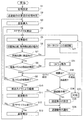
- FIG. 5 is a flow chart showing the main operation flow of the control device 6 that controls the mounting operation of the component P.
- the operation flow of FIG. 5 is performed for each type of substrate K to be produced.
- FIG. 6 is a flowchart showing a detailed operation flow of the retry operation included in FIG.
- step S1 of FIG. 5 the control device 6 performs initial setting. More specifically, the retraction control unit 75 of the control device 6 sets the normal height (HSn, HMn, HLn) when the mounting head (45, 46, 47) moves. Further, the component type registration unit 79 registers in advance the type of the component P to be subjected to the retry operation. For example, when the information indicating whether or not the component P is the target of the retry operation is described in the component data, the component type registration unit 79 can search for the component data and perform registration. Alternatively, the component type registration unit 79 can perform registration based on the input operation of the operator. On the other hand, the coping method setting unit 78 sets in advance a coping method when the retry operation is unsuccessful.
- the save control unit 75 performs an initial determination as to whether or not the save operation is necessary. For example, when the component P mounted on a certain type of substrate K is only large and only the large mounting head 47 having the large suction nozzle 472 is used, the retraction operation is unnecessary. Further, for example, even in the case where only the small component P is mounted using the small mounting head 45 having the small suction nozzle 452, the retraction operation is unnecessary. On the other hand, when the mounting head (45, 46, 47) is automatically replaced in the middle of the mounting operation, there is a possibility of interference due to the drop of the component P, so it is necessary to consider the possibility of the retraction operation. In practice, the sizes of the parts P are various and the judgment logic of the initial judgment is complicated to some extent.
- the evacuation control unit 75 resets the evacuation flag when the evacuation operation is unnecessary, and sets the evacuation flag when considering the evacuation operation.
- the control device 6 controls the substrate transfer device 2 to carry in and position the substrate K.
- the control device 6 controls the component supply device 3 and the component transfer device 4 to start the mounting operation of the component P, that is, the PP cycle.
- the control device 6 causes the component transfer device 4 to perform the suction operation of the component P using the suction nozzles (452, 462, 472).
- the component transfer device 4 rotationally drives the rotary tool 451 clockwise by a predetermined angle A.
- the feeder device 31 feeds the carrier tape 9 by a constant pitch and advances the next cavity portion 93 to the supply position 34.
- step S6 the component detection unit 71 and the holding detection unit 72 operate.
- step S7 the drop determination unit 74 and the retry performing unit 77 check whether the part P is present in the cavity 93 of the supply position 34, that is, the detection result of the part detector 71. Normally, there is a part P at the supply position 34, and execution of the operation flow is advanced to step S8.
- step S8 the drop determination unit 74 and the retry performing unit 77 check the detection result of the holding detection unit 72, that is, whether or not the suction nozzle (452, 462, 472) holds the component P. Usually, the part P is held, and the execution of the operation flow is advanced to step S9.
- step S9 the control device 6 determines whether the suction operation of all the suction nozzles (452, 462, 472) has ended. If not, the control device 6 returns the operation flow to step S5 for the next suction nozzle (452, 462, 472). By repeating the loop from step S5 to step S9, the suction operation of all the suction nozzles (452, 462, 472) is completed. Then, the control device 6 advances the execution of the operation flow to step S10. Note that, depending on the contents of the PP cycle described in the mounting sequence 62, only some of the suction nozzles (452, 462, 472) may be used.
- step S10 the component transfer device 4 moves the mounting head (45, 46, 47) above the component camera 5. Thereby, imaging with the component camera 5 is performed.
- step S11 the component transfer device 4 moves the mounting head (45, 46, 47) to the substrate K and performs the mounting operation of the component P.
- step S12 the control device 6 determines whether all the PP cycles have ended. If not, the control device 6 returns the execution of the operation flow to step S4 for the next PP cycle. The repetition of the loop from step S4 to step S12 completes the entire PP cycle. Then, the control device 6 advances the execution of the operation flow to step S13.
- step S13 the control device 6 carries out the substrate K for which production has been completed. Thereafter, the control device 6 returns the execution of the operation flow to step S3 and starts the mounting operation to the next substrate K.
- the substrate K is mass-produced by repeating the loop from step S3 to step S13. In some cases, unloading of the substrate K for which production has been completed and loading of the next substrate K may be performed simultaneously. This is the explanation of the good progress of the main operation flow.
- step S21 the operation flow branches to step S21.
- the component P is not accommodated in the cavity portion 93 of the carrier tape 9 from the beginning. More specifically, several cavities near the front end and the rear end of the carrier tape 9 are empty cavities where no parts are accommodated from the beginning.
- the empty cavity portion is cut by the operator or stored in advance in the control device 6 so that the suction operation is omitted. Even so, the empty cavity may be determined to be a normal cavity 93 and the suction operation may be performed due to the operator's failure in the cutting operation or an error in the number of empty cavities. In addition, although it is rare, there are cases where parts are not accommodated in the normal cavity 93.
- step S21 the control device 6 rotates the rotary tool 451 counterclockwise by a predetermined angle A in the reverse direction, and returns the execution of the operation flow to step S5.
- step S5 the component transfer device 4 performs the suction operation from the next cavity portion 93 of the carrier tape 9 using the suction nozzles (452, 462, 472) that could not suction the component P again.
- FIG. 7 is a plan view showing a first case in which the small suction nozzle 452 does not hold the component P after the single suction operation is completed from the state of FIG.
- FIG. 8 is a plan view showing a second case in which the small suction nozzle 452 does not hold the component P after the single suction operation is completed from the state of FIG.
- step S6 the side-view camera 457 captures a situation in which the fifth small suction nozzle 452 does not hold the component P.
- step S31 the branch from step S8 to step S31 is executed.
- the carrier tape 9 is fed by a constant pitch from the situation of FIG.
- the component P remains in the cavity 93X advanced from the supply position 34. Therefore, in the first case, the component P is present in the cavity 93X during the suction operation, and the small suction nozzle 452 can not suction the component P.
- step S31 the retry performing unit 77 of the control device 6 performs the retry operation regardless of the first case and the second case.
- step S51 of FIG. 6 showing details of the retry operation, the retry performing unit 77 sets 1 in the retry counter RC for counting the number of retries.
- the retry performing unit 77 returns the carrier tape 9 by a predetermined pitch, and repositions the cavity portion 93X, which is unclear whether or not the part P remains, at the supply position 34.
- the retry performing unit 77 rotates the rotary tool 451 counterclockwise by a predetermined angle A in the reverse direction to reposition the fifth small suction nozzle 452 at the suction position 459.
- the retry performing unit 77 causes the component transfer device 4 to perform the same suction operation as in step S5. As described above, the rotary drive of the rotary tool 451 and the delivery of the carrier tape 9 are performed in conjunction with the suction operation. In the next step S55, the component detection unit 71, the holding detection unit 72, and the remaining detection unit 73 operate.
- step S56 the drop determination unit 74 and the retry performing unit 77 determine the branch destination of the operation flow based on the detection results of the component detection unit 71 and the remaining detection unit 73.
- step S57 when there is no part P (does not remain), the drop determination unit 74 determines that the “part drop” of the second case occurs. Thereafter, the drop determination unit 74 returns the execution of the control to the main operation flow.
- step S58 when there is a part P (remaining), the retry performing unit 77 determines the branch destination of the operation flow based on the detection result of the holding detection unit 72.
- step S59 when the component P is held by the suction nozzle (452, 462, 472), the retry performing unit 77 determines that “retry is successful” after the first case. Thereafter, the retry performing unit 77 returns the execution of the control to the main operation flow.
- step S60 when the component P is not held by the suction nozzle (452, 462, 472), the retry performing unit 77 determines whether the value of the retry counter RC has reached a predetermined number N of times.
- step S61 when it has not reached, the retry performing unit 77 increases the value of the retry counter RC by 1 and returns the execution of the operation flow to step S52.
- the suction operation of step S54 is executed a predetermined number of times N at maximum.
- step S57 or step S59 may occur.
- the value of the retry counter RC reaches the predetermined number N in step S60, and execution of the operation flow is advanced to step S62.
- step S62 the retry performing unit 77 controls the execution of the end process.
- the end processing does not aim at suction of the part P, but aims at final confirmation of whether or not the part P remains.
- the retry performing unit 77 weakens the negative pressure supplied from the internal pressure control unit 455 to the suction nozzles (452, 462, 472) to perform the suction operation.
- the residual detection unit 73 includes the height measurement sensor, only the descent operation is performed without supplying the negative pressure to the suction nozzles (452, 462, and 472).
- the retry performing unit 77 determines the branch destination of the operation flow based on the detection result of the remaining detection unit 73 at the end processing time. If the part P does not remain, the retry performing unit 77 joins the execution of the operation flow to the “part drop” in step S57. In addition, in step S64 in the case where the part P remains, the retry performing unit 77 determines that “retry is not successful” after the first case. Thereafter, the retry performing unit 77 returns the execution of the control to the main operation flow.
- the “retry failure” occurs when the part P is fixed to the cavity 93X or when the cover tape 92 covering the cavity 93X is not peeled off.
- the result of the retry operation is one of “retry success”, “retry failure”, and “part drop”.
- the retry performing unit 77 determines the branch destination of the operation flow according to the result of the retry operation. In the case of “retry success”, the retry performing unit 77 returns the execution of the operation flow to step S9.
- step S33 in the case of "retry failure” the control device 6 implements the countermeasure method initialized in step S1.
- step S34 in the case of “part drop” the evacuation control unit 75 finally determines whether or not the evacuation operation is necessary, and determines the branch destination of the operation flow. More specifically, when the save flag is reset in step S2, the save control unit 75 can immediately determine that the save operation is unnecessary. In addition, when the retraction flag is set, the retraction control unit 75 compares the size of the part P actually dropped with the type of the mounting head (45, 46, 47) to be used from now, and performs the retraction operation. Determine the necessity.
- the small mounting head 45 when the dropped part P is large, it is necessary to retract the small mounting head 45 and the medium mounting head 46, as is apparent from the description of FIG. In addition, when the dropped part P is medium-sized, the small mounting head 45 needs to retract. When the dropped part P is small, the retraction operation is unnecessary.
- step S35 when the retraction operation is necessary, the retraction control unit 75 retracts the height HSs of the small mounting head 45 and the retraction height of the middle mounting head 46 when the dropped part P is large. Set HMs. Further, the retraction control unit 75 sets only the retraction height HSs of the small-sized mounting head 45 when the dropped part P is medium-sized. When a plurality of parts P are dropped due to the repetition of the operation flow, the evacuation control unit 75 performs setting in consideration of the largest part P among the dropped parts.
- step S36 the save operation notification unit 76 notifies the control execution state of the save operation.
- the save control unit 75 omits step S35 and advances the execution of the operation flow to step S36.
- step S36 in this case, the evacuation operation notification unit 76 notifies that the small part P has been dropped.
- the evacuation control unit 75 merges the execution of the operation flow with step S21.
- the withdrawal heights (HSs, HMs) set in step S35 are continuously used until the production of a predetermined number of substrates K is finished. However, when the operator takes care of the dropped part P and the restart process is subsequently performed, the evacuation heights (HSs, HMs) are normally returned to the heights (HSn, HMn).
- logic is indirectly and logically based on the detection results of the component detection unit 71, the holding detection unit 72, and the remaining detection unit 73 without directly detecting the dropped component P. It can be determined whether or not the part P has dropped. Further, the component detection unit 71, the holding detection unit 72, and the remaining detection unit 73 can be realized by utilizing an existing device configuration, instead of newly providing a sensor or the like. Therefore, the increase in cost required to determine the part drop is suppressed.
- the component mounting machine 1 of the embodiment when suctioning the component P using the suction nozzle (452, 462, 472), it is detected whether or not there is a component at the supply position 34, and It is detected whether 452, 462, 472) holds the part P, and it is determined based on the detection result whether or not to execute the retry operation. Therefore, when there is no part P at the supply position 34 from the beginning, meaningless retry operation can be avoided.
- control device 6 may perform only one control of the control related to the drop determination of the part P and the control related to the retry operation when the part P can not be adsorbed.
- the component supply device 3 is configured by the feeder device 31, and the suction nozzles (452, 462, 472) are used as the component mounting tool, but the invention is not limited thereto. That is, the component supply device 3 may be a device using a tray as a component supply medium or a component supply device of the other type. Further, as the component mounting tool, a clamping type mounting tool for gripping the component P can also be used.
- the configuration may be such that the mounting heads (45 to 47) are manually replaced, or that the mounting heads are not replaced.
- the detection operation (step S55 in FIG. 6) of the component detection unit 71, the holding detection unit 72, and the remaining detection unit 73 during the retry operation is a detection method different from the normal detection operation (step S6 in FIG. 5) You may go there.
- the embodiment is capable of various other modifications and applications.
- Component mounting device 2 Substrate transfer device 3: Component supply device 31: Feeder device 34: Supply position 4: Component transfer device 45: Small mounting head 451: Rotary tool 452: Small suction nozzle 453: Rotational drive unit 454: Lifting drive 456: Negative pressure measuring sensor 457: Side-view camera 458: Detection position 459: Suction position 46: Medium-sized mounting head 462: Medium-sized adsorption nozzle 47: Large-sized installation head 472: Large-sized adsorption nozzle 6: Control device 71: component detection unit 72: retention detection unit 73: residual detection unit 74: drop determination unit 75: evacuation control unit 76: evacuation operation notification unit 77: retry execution unit 78: action method setting unit 79: component type registration unit 9: Carrier tape 93: Yabiti unit 93X: cavity K: the substrate P: Component A: a predetermined angle HSn: Normal Height HMn: Normal Height HLn: Normal Height HSS: retraction height HMS:
Abstract
部品を供給位置に供給する部品供給装置と、部品装着具を用いて前記供給位置から前記部品を採取し基板に装着する部品移載装置と、を備えた部品装着機であって、前記部品装着具を用いて前記部品を採取する以前または採取する際に、前記供給位置に前記部品が有るか否かを検出する部品検出部と、前記部品装着具が前記部品を採取して保持しているか否かを検出する保持検出部と、前記部品検出部の検出結果、および前記保持検出部の検出結果に基づき、前記部品装着具を用いて再び前記部品を採取するリトライ動作を実施するか否かを判定し、判定結果に基づいて前記リトライ動作を実施するリトライ実施部と、を備える。
Description
本明細書は、基板に電子部品(以下、部品と略称する)を装着する装着作業を実施する部品装着機に関する。
プリント配線が施された基板に部品を装着するための諸作業(以下、対基板作業と称する)を実施して、回路基板を量産する技術が普及している。対基板作業を実施する対基板作業機として、半田印刷機、部品装着機、リフロー機、基板検査機などがある。部品装着機は、一般的に、基板搬送装置、部品供給装置、および部品移載装置を備える。部品移載装置は、吸着ノズルを保持する装着ヘッド、および装着ヘッドを水平二方向に駆動するヘッド駆動機構などで構成される。そして、吸着ノズルを用いて部品を吸着できない場合がごく稀に発生する。この場合、高価な部品に対してリトライ動作を実施することが多い。部品吸着のリトライ動作に関する技術例が特許文献1、2に開示されている。
特許文献1の部品装着機では、移載ヘッドによる部品の吸着に失敗した場合には、次の吸着時にキャリアテープの送り動作を行わず、もしくは、送り動作を行ったキャリアテープの逆送り動作を行う。これによれば、供給位置に残された部品に対してリトライ動作を行え、部品を廃棄せずに無駄を軽減できる、とされている。
また、特許文献2の部品装着ヘッドでは、吸着ノズルで部品を吸着する際に、吸着ノズルを昇降させるボイスコイルモータの負荷を検知して、吸着ノズルが部品に当接したことを判断する。これによれば、部品の形状や大きさに左右されることなく、部品を吸着できたか否の判断を正確かつ迅速に行える、とされている。
ところで、顧客によっては、使用済みのキャリアテープから採取されなかった部品を回収して使用し、廃棄率を低減している。これに対し、特許文献1の技術は、リトライ動作によって部品の無駄を軽減でき、なおかつ部品回収の手間を省略できる点で好ましい。しかしながら、無意味なリトライ動作を行うおそれが生じる。例えば、キャリアテープの先端や後端に近い数個のキャビティ部は、初めから部品が収容されていない空キャビティ部となっている。また、稀ではあるが、通常のキャビティ部に部品が収容されていない場合もある。空キャビティ部に対する意味のないリトライ動作は、部品装着機の生産効率を低下させる。このような問題点は、吸着ノズルとキャリアテープの組み合わせに限定されず、他の種類の部品装着具や他の種類の部品供給媒体についても考慮する必要がある。
本明細書では、部品採取時の無意味なリトライ動作を回避できる部品装着機、および部品採取のリトライ方法を提供することを解決すべき課題とする。
本明細書は、部品を供給位置に供給する部品供給装置と、部品装着具を用いて前記供給位置から前記部品を採取し基板に装着する部品移載装置と、を備えた部品装着機であって、前記部品装着具を用いて前記部品を採取する以前または採取する際に、前記供給位置に前記部品が有るか否かを検出する部品検出部と、前記部品装着具が前記部品を採取して保持しているか否かを検出する保持検出部と、前記部品検出部の検出結果、および前記保持検出部の検出結果に基づき、前記部品装着具を用いて再び前記部品を採取するリトライ動作を実施するか否かを判定し、判定結果に基づいて前記リトライ動作を実施するリトライ実施部と、を備える部品装着機を開示する。
また、本明細書は、部品を供給位置に供給する部品供給装置と、部品装着具を用いて前記供給位置から前記部品を採取し基板に装着する部品移載装置と、を備えた部品装着機における部品採取のリトライ方法であって、前記部品装着具を用いて前記部品を採取する以前または採取する際に、前記供給位置に前記部品が有るか否かを検出する部品検出工程と、前記部品装着具が前記部品を採取して保持しているか否かを検出する保持検出工程と、前記部品検出工程の検出結果、および前記保持検出工程の検出結果に基づき、前記部品装着具を用いて再び前記部品を採取するリトライ動作を実施するか否かを判定し、判定結果に基づいて前記リトライ動作を実施するリトライ実施工程と、を備える部品採取のリトライ方法を開示する。
本明細書で開示する部品装着機によれば、部品装着具を用いて部品を採取する以前または採取する際に供給位置に部品が有るか否かを検出し、さらに部品装着具が部品を保持しているか否かを検出し、検出結果に基づいてリトライ動作を実施するか否かを判定する。したがって、初めから供給位置に部品が無い場合に、無意味なリトライ動作を回避できる。また、本明細書で開示する部品採取のリトライ方法によれば、前述した部品装着機の効果と同様の効果が得られる。
1.実施形態の部品装着機1の構成
実施形態の部品装着機1について、図1~図8を参考にして説明する。図1は、実施形態の部品装着機1の構成を模式的に示す平面図である。図1の紙面左側から右側に向かう方向が基板Kを搬送するX軸方向、紙面下側から紙面上側に向かう方向がY軸方向(前後方向)である。図2は、実施形態の部品装着機1の制御の構成を示すブロック図である。部品装着機1は、基板搬送装置2、部品供給装置3、部品移載装置4、部品カメラ5、および制御装置6などが機台10に組み付けられて構成されている。基板搬送装置2、部品供給装置3、部品移載装置4、および部品カメラ5は、制御装置6から制御されて、それぞれ所定の作業を担当する。
実施形態の部品装着機1について、図1~図8を参考にして説明する。図1は、実施形態の部品装着機1の構成を模式的に示す平面図である。図1の紙面左側から右側に向かう方向が基板Kを搬送するX軸方向、紙面下側から紙面上側に向かう方向がY軸方向(前後方向)である。図2は、実施形態の部品装着機1の制御の構成を示すブロック図である。部品装着機1は、基板搬送装置2、部品供給装置3、部品移載装置4、部品カメラ5、および制御装置6などが機台10に組み付けられて構成されている。基板搬送装置2、部品供給装置3、部品移載装置4、および部品カメラ5は、制御装置6から制御されて、それぞれ所定の作業を担当する。
基板搬送装置2は、基板Kの搬送作業および位置決め作業を担当する。基板搬送装置2は、搬送ユニット25およびバックアップユニット26からなる。搬送ユニット25は、一対のガイドレール21、22、および一対のコンベアベルトなどで構成される。一対のガイドレール21、22は、機台10の上面中央のX軸方向に延在し、かつ、互いに平行して配置される。一対のガイドレール21、22の向かい合う内側に、図略の無端環状の一対のコンベアベルトが設けられる。一対のコンベアベルトは、長方形の基板Kの対向する辺をそれぞれ戴置した状態で輪転して、基板Kを機台10の中央部に設定された装着実施位置に搬入および搬出する。バックアップユニット26は、装着実施位置の下方に配設される。バックアップユニット26は、基板Kを押し上げて水平姿勢でクランプし、装着実施位置に位置決めする。これにより、部品移載装置4が装着作業を行えるようになる。
部品供給装置3は、部品の供給作業を担当する。部品供給装置3は、パレット台30および複数のフィーダ装置31などで構成される。パレット台30は、概ね矩形板状であり、機台10の上面の前側に着脱可能に装備される。フィーダ装置31は、幅方向に薄く形成されており、パレット台30上に並べて装備される。図1には、4個のフィーダ装置31が例示されており、実際には、さらに多数のフィーダ装置31が並設される。生産する基板Kの種類に応じて供給する部品の種類を変更するために、フィーダ装置31は適宜交換され、あるいは、部品供給装置3の全体が交換される。
フィーダ装置31は、本体部32、および本体部32の前側に交換可能にセットされるテープリール33などで構成される。本体部32の後端付近の上部に、供給位置34が設定されている。テープリール33には、部品供給媒体としてのキャリアテープ9(図3参照)が巻回保持されている。図3は、部品Pの吸着動作の状況を例示する図であって、フィーダ装置31、および部品移載装置4の小形装着ヘッド45を模式的に示した平面図である。図3において、部品Pは、黒塗りで示される。
図3に示されるように、キャリアテープ9は、ボトムテープ91、およびボトムテープ91に貼設されたカバーテープ92からなる。ボトムテープ91は、紙製や樹脂製とされ、部品Pを収容するキャビティ部93が一定ピッチで形成されている。カバーテープ92は、透明フィルム製などとされ、キャビティ部93を覆う。フィーダ装置31は、キャリアテープ9を一定ピッチずつ繰り出して、順次キャビティ部93を供給位置34に進める。このとき、図略の剥離機構によってカバーテープ92がボトムテープ91から剥離されて屈曲される。これにより、供給位置34のキャビティ部93から部品Pを取り出せる状態となる。
部品移載装置4は、部品の装着作業を担当する。部品移載装置4は、X軸方向およびY軸方向に水平移動可能なXYロボットタイプの装置である。部品移載装置4は、一対のY軸レール41、42、Y軸スライダ43、X軸スライダ44、選択取り付け可能な複数種類の装着ヘッド(45~47)、および基板カメラ48などで構成される。一対のY軸レール41、42は、機台10の両方の側面寄りに配置されて、Y軸方向に延在する。Y軸スライダ43は、Y軸レール41、42に移動可能に装架される。Y軸スライダ43は、Y軸ボールねじ機構431によってY軸方向に駆動される。
X軸スライダ44は、Y軸スライダ43に移動可能に装架される。X軸スライダ44は、X軸ボールねじ機構441によってX軸方向に駆動される。X軸スライダ44は、X軸スライダ44に対して装着ヘッド(45~47)を昇降させるヘッド昇降装置445を備える。複数種類の装着ヘッド(45~47)として、小形装着ヘッド45、中形装着ヘッド46、および大形装着ヘッド47が用いられる。これらの装着ヘッド(45~47)は、機台10上のヘッド交換ステーション11に並べて配置される。そして、ヘッド昇降装置445により装着ヘッド(45~47)が昇降駆動されて、装着ヘッド(45~47)が自動交換される。図1は、小形装着ヘッド45が選択されて取り付けられた状態を例示している。
小形装着ヘッド45は、ロータリツール451、小形吸着ノズル452、回転駆動部453、昇降駆動部454、内圧制御部455、負圧測定センサ456、および側視カメラ457などを有する。ロータリツール451は、小形装着ヘッド45の下側に回転可能に保持される。ロータリツール451には、16個のノズルホルダが所定角度Aの間隔で環状に配置される。各ノズルホルダは、弾性部材を介して16本の小形吸着ノズル452を上下動可能に保持する。16本の小形吸着ノズル452は、小形の部品Pの装着を担当する。
小形装着ヘッド45がいずれかのフィーダ装置31の供給位置34の上方まで駆動されたとき、1個のノズルホルダおよび1本の小形吸着ノズル452が吸着位置459に位置決めされる。図3に示されるように、吸着位置459は、フィーダ装置31の供給位置34の真上の位置である。昇降駆動部454は、吸着位置459のノズルホルダを昇降駆動する。吸着位置459の小形吸着ノズル452が下降駆動されたとき、内圧制御部455は、当該の小形吸着ノズル452に負圧を供給する。
これにより、吸着位置459の小形吸着ノズル452は、供給位置34まで下降して、下端開口部で部品Pを吸着する。負圧測定センサ456は、小形吸着ノズル452が吸着動作を行っているときに、小形吸着ノズル452の内部の負圧を測定する。小形吸着ノズル452の下端開口部が部品Pに接すると、大気エアの吸入が阻止されて、小形吸着ノズル452の負圧が顕著に低下する。仮に部品Pが存在しない場合、大気エアの吸入が継続するため、小形吸着ノズル452の負圧があまり低下しない。したがって、負圧測定センサ456の測定結果に基づいて、部品Pの有無が検出される。負圧測定センサ456は、後述する部品検出部71および残存検出部73の一部として機能する。
第1の小形吸着ノズル452が部品Pを吸着して上昇すると、回転駆動部453は、ロータリツール451を所定角度A(図3参照)だけ時計回りに回転駆動する。これにより、第1の小形吸着ノズル452は、吸着位置459から回転移動して、検出位置458に位置決めされる。同時に、第1の小形吸着ノズル452の隣の第2の小形吸着ノズル452は、吸着位置459に位置決めされる。なお、第1の小形吸着ノズル452の上昇動作と、ロータリツール451の回転とが時間的にオーバーラップしてもよい。
上記した小形吸着ノズル452の吸着動作、およびロータリツール451の回転動作は、繰り返して行われる。これにより、16本またはその一部の小形吸着ノズル452は、部品Pを吸着して保持する。図3において、4本の小形吸着ノズル452による部品Pの吸着が既に終了しており、5本目の小形吸着ノズル452による部品Pの吸着が実施されている。回転駆動部453は、さらに、ロータリツール451を逆方向の反時計回りに回転駆動する機能を有する。これによれば、後述するリトライ動作で、小形吸着ノズル452を検出位置458から吸着位置459へと短時間で戻すことができる。
側視カメラ457は、検出位置458に位置する第1の小形吸着ノズル452の下端開口部の付近を撮像できる位置に配置される。側視カメラ457は、第1の小形吸着ノズル452を側方から撮像して、取得した画像データを画像処理することにより、第1の小形吸着ノズル452が部品Pを吸着しているか否かを検出する撮像画像処理部である。側視カメラ457は、後述する保持検出部72の一部として機能する。また、小形装着ヘッド45が基板Kの上方まで駆動されたとき、吸着位置459の小形吸着ノズル452は、昇降駆動部454によって下降駆動され、内圧制御部455から正圧が供給されて、部品Pを基板Kに装着する。
中形装着ヘッド46および大形装着ヘッド47も、小形装着ヘッド45と類似の構成である。ただし、中形装着ヘッド46は、4本の中形吸着ノズル462を有する。中形吸着ノズル462は、中形の部品Pの装着を担当する。大形装着ヘッド47は、2本の大形吸着ノズル472を有する。大形吸着ノズル472は、大形の部品Pの装着を担当する。
前述したように、装着ヘッド(45、46、47)、吸着ノズル(452、462、472)、および部品Pの組み合わせは、それぞれ小形同士、中形同士、および大形同士で対応するものとした。これにより、以降の動作等の説明が簡単明瞭化される。実際には、部品Pの大きさは多種多様であり、装着ヘッド(45、46、47)や吸着ノズル(452、462、472)も3種類以上ある場合が多い。また、装着ヘッド(45、46、47)を交換せずに、吸着ノズル(452、462、472)のみを交換する構成など、使用形態にもバリエーションがある。
基板カメラ48は、X軸スライダ44の装着ヘッド(45、46、47)に並ぶ位置に、下向きに設けられる。基板カメラ48は、基板Kに付設された位置基準マークを撮像して、基板Kの正確な位置を検出する。基板カメラ48は、後述する部品検出部71および残存検出部73の一部として機能することも可能である。
部品移載装置4は、吸着装着サイクル(以下、PPサイクルと称す)を繰り返すことによって、装着作業を進める。PPサイクルの動作について詳述すると、部品移載装置4は、まず、装着ヘッド(45、46、47)を部品供給装置3に移動して、複数本の吸着ノズル(452、462、472)でそれぞれ部品Pを吸着する。部品移載装置4は、次に、装着ヘッド(45、46、47)を部品カメラ5の上方に移動する。このとき、部品カメラ5により、複数の部品Pの保持状態が撮像される。部品移載装置4は、その次に、装着ヘッド(45、46、47)を基板Kに移動して複数の部品Pを装着し、再び部品供給装置3に戻る。
基板Kに装着する部品Pの大きさに応じて、小形装着ヘッド45、中形装着ヘッド46、および大形装着ヘッド47は、自動交換される。例えば、或る種類の基板Kに小形および大形の部品Pを装着するとき、1枚の基板Kへの装着作業の途中で、小形装着ヘッド45と大形装着ヘッド47とが自動交換して用いられる。一般的な装着順序としては、小形装着ヘッド45の何回かのPPサイクルが最初で、次に中形装着ヘッド46のPPサイクル、最後に大形装着ヘッド47のPPサイクルとなる。ただし、基板Kや部品Pの種類によっては、装着順序の例外もある。
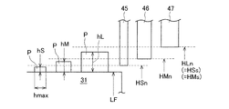
ここで、小形装着ヘッド45、中形装着ヘッド46、および大形装着ヘッド47が水平方向に移動するときの高さについて説明する。図4は、3種類の装着ヘッド(45、46、47)が水平方向に移動するときの高さを模式的に説明する図である。図4において、高さレベルLFは、フィーダ装置31の上面の高さを表す。吸着動作の際に誤って落下させた部品Pは、多くの場合にフィーダ装置31の上面に留まる。この場合、装着ヘッド(45、46、47)は、移動する際に落下した部品Pに干渉して破損するおそれがある。また、吸着ノズル(452、462、472)に吸着された部品Pは、落下した部品Pに衝突するおそれがある。
そこで、小形装着ヘッド45の下端部分が水平方向に移動する通常高さHSnは、高さレベルLFに小形の部品Pの高さ寸法hSを考慮した高さよりもわずかに高く設定される。多くの小形装着ヘッド45の構造では、小形吸着ノズル452に吸着された部品Pの底面が下端部分となるが、これに限定されない。なお、小形の部品Pの装着姿勢における高さ寸法hSに代えて、部品Pの長辺寸法hmaxを考慮してもよい。これによれば、落下した部品Pが仮に起立状態となっても干渉のおそれが無く、さらに信頼性が高められる。
また、中形装着ヘッド46の通常高さHMnは、高さレベルLFに中形の部品Pの高さ寸法hMを考慮した高さよりもわずかに高く設定される。さらに、大形装着ヘッド47の通常高さHLnは、高さレベルLFに大形の部品Pの高さ寸法hLを考慮した高さよりもわずかに高く設定される。通常高さ(HSn、HMn、HLn)の設定は、装着ヘッド(45、46、47)の自動交換に併せて実施される。
通常高さ(HSn、HMn、HLn)の設定により、装着作業の途中で装着ヘッド(45、46、47)を自動交換しない場合に、装着ヘッド(45、46、47)と落下した部品Pとの干渉が未然防止される。しかしながら、装着ヘッド(45、46、47)を自動交換する場合に、干渉のおそれは解消されない。例えば、小形装着ヘッド45は、通常高さHSnで移動すると、落下した中形や大形の部品Pに干渉する。また例えば、中形装着ヘッド46は、通常高さHMnで移動すると、落下した大形の部品Pに干渉する。
そこで、小形装着ヘッド45に退避高さHSsが設定され、中形装着ヘッド46に退避高さHMsが設定される。退避高さHSsおよび退避高さHMsは、落下した部品Pの大きさに関係なく干渉のおそれを解消できる高さである。本実施形態において、退避高さHSsおよび退避高さHMsは、大形装着ヘッド47の通常高さHLnに等しく設定される。また、大形装着ヘッド47に関しては、通常高さHLnで干渉のおそれが無いので、退避高さは設定されない。なお、後述する退避制御部75は、落下した部品Pの大きさを考慮して、退避高さを可変に設定してもよい。通常高さ(HSn、HMn、HLn)および退避高さ(HSs、HMs)の切り替えは、退避制御部75がヘッド昇降装置445を制御することによって行われる。
部品カメラ5は、基板搬送装置2と部品供給装置3との間の機台10の上面に、上向きに設けられている。部品カメラ5は、装着ヘッド(45、46、47)が部品供給装置3から基板Kに移動する途中で、吸着ノズル(452、462、472)に保持されている部品Pの状態を撮像する。取得された撮像データの画像処理によって部品Pの保持姿勢の誤差や回転角のずれなどが判明すると、制御装置6は、必要に応じて装着作業を微調整し、装着作業が困難な場合には当該の部品Pを廃棄する制御を行う。
2.実施形態の部品装着機1の制御の構成および機能
次に、実施形態の部品装着機1の制御の構成および機能について説明する。制御装置6は、機台10に組み付けられており、その配設位置は特に限定されない。制御装置6は、CPUを有してソフトウェアで動作するコンピュータ装置である。図2に示されるように、制御装置6は、記憶部61内に装着シーケンス62を保持している。装着シーケンス62は、基板Kに装着する部品Pの種類、装着座標位置、および装着順序、当該の部品を供給するフィーダ装置31などを指定したデータである。
次に、実施形態の部品装着機1の制御の構成および機能について説明する。制御装置6は、機台10に組み付けられており、その配設位置は特に限定されない。制御装置6は、CPUを有してソフトウェアで動作するコンピュータ装置である。図2に示されるように、制御装置6は、記憶部61内に装着シーケンス62を保持している。装着シーケンス62は、基板Kに装着する部品Pの種類、装着座標位置、および装着順序、当該の部品を供給するフィーダ装置31などを指定したデータである。
制御装置6は、装着シーケンス62にしたがって、部品装着機1の作業の流れを制御する。また、制御装置6は、生産完了した基板Kの生産数や、部品Pの装着に要した装着時間、部品Pの吸着エラーの発生回数などの稼動状況データを逐次収集して更新する。制御装置6は、上位の制御装置であるホストコンピュータ69に通信接続され、指令や応答などを授受する。
さらに、制御装置6は、部品Pの落下判定に関する制御、および部品Pを吸着できなかったときのリトライ動作に関する制御を行う。制御装置6は、落下判定およびリトライ動作の両方に関する機能部として、部品検出部71および保持検出部72を有する。制御装置6は、落下判定に関する機能部として、残存検出部73、落下判定部74、退避制御部75、および退避動作通知部76を有する。制御装置6は、リトライ動作に関する機能部として、リトライ実施部77、対処方法設定部78、および部品種登録部79を有する。
部品検出部71は、吸着ノズル(452、462、472)を用いて部品Pを吸着する際に、フィーダ装置31の供給位置34に部品Pが有るか否か検出する。本実施形態において、部品検出部71は、前述した負圧測定センサ456を用い、供給位置34に位置するキャビティ部93に部品Pが有るか否か検出する。これに限定されず、部品検出部71の構成には、いくつかの別の態様がある。
例えば、部品検出部71は、ノズルホルダを基準とする吸着ノズル(452、462、472)の相対高さを測定して、吸着ノズル(452、462、472)が部品Pに接したことを検出する高さ測定センサを含んでもよい。詳述すると、ノズルホルダが下降する途中で、吸着ノズル(452、462、472)が部品Pに接すると以後は下降しなくなり、ノズルホルダの下降だけが継続する。このため、ノズルホルダを基準とする吸着ノズル(452、462、472)の相対高さが変化する。したがって、高さ測定センサは、相対高さの変化を以って、部品Pが有ることを検出できる。
高さ測定センサとして、ノズルホルダに設けられた遮光センサを例示できる。この遮光センサは、吸着ノズル(452、462、472)の特定高さに付設された遮光部を検出して、相対高さの変化を検出する。また、部品検出部71は、部品Pを吸着する以前に基板カメラ48を用いてキャビティ部93を撮像し、取得した画像データの画像処理によって部品Pの有無を検出してもよい。
保持検出部72は、吸着ノズル(452、462、472)が部品Pを吸着して保持しているか否かを検出する。例えば、小形装着ヘッド45が取り付けられている場合、保持検出部72は、前述した側視カメラ457を用いて、検出位置458に位置する小形吸着ノズル452が部品Pを保持しているか否かを検出する。
残存検出部73は、保持検出部72によって吸着ノズル(452、462、472)が部品Pを保持していないことが検出された場合に、供給位置34に部品Pが残存しているか否かを検出する。残存検出部73は、部品検出部71の構成が兼用されており、部品検出部71と同じ動作をする。実際には、部品検出部71の「部品Pの有り/無し」の検出結果が、残存検出部73の「部品Pが残存している/残存していない」の検出結果に流用される。
落下判定部74は、部品検出部71の検出結果、保持検出部72の検出結果、および残存検出部73の検出結果に基づいて、部品Pが落下したか否かを判定する。具体的に、部品検出部71によって供給位置34に部品Pが有ることが検出され、かつ、保持検出部72によって吸着ノズル(452、462、472)が部品Pを保持していないことが検出され、さらに、残存検出部73によって供給位置34に部品Pが残存していないことが検出された場合に、落下判定部74は、部品Pが落下したと判定する。つまり、供給位置34に有った部品Pが吸着動作で無くなり、かつ吸着ノズル(452、462、472)が部品Pを保持していない場合に、部品Pを誤って落下させたことを論理的に判定できる。部品Pの落下の有無の判定結果は、退避制御部75に受け渡される。
なお、部品検出部71、保持検出部72、残存検出部73、および落下判定部74は、所定の大きさ以上の部品Pを落下判定の対象とする。具体的には、中形および大形の部品Pが落下判定の対象とされ、仮に落下しても干渉しない小形の部品Pは対象外とされる。これにより、検出や判定に要する時間が削減されて、生産効率が向上する。
例えば、部品検出部71が高さ測定センサを含む場合に、相対高さの変化を顕在化させる目的で、ノズルホルダを通常位置よりも低い位置まで降下させる。対象外の小形の部品Pについては、ノズルホルダを通常位置まで降下させればよく、検出に要する時間が削減される。また、部品検出部71が基板カメラ48を含む場合に、小形の部品Pが収容されたキャビティ部93を撮像して画像処理する時間が削減される。
退避制御部75は、落下判定部74によって部品Pが落下したと判定された場合に、退避高さ(HSs、HMs)で装着ヘッド(45、46)を移動させる退避動作を制御する。さらに、退避制御部75は、吸着ノズル(452、462、472)の種類、装着ヘッド(45、46、47)の種類、落下した部品Pの大きさ、およびこれから吸着する部品Pの大きさの少なくとも一項目に基づいて、退避動作の要否を判定する。
退避動作により、仮に部品Pが落下しても、基板Kの生産が継続される。しかしながら、通常高さ(HSn、HMn)よりも高い退避高さ(HSs、HMs)を用いる分だけ生産効率が低下する。また、落下した部品Pを放置することは、本来好ましくない。このため、退避動作通知部76は、退避制御部75の制御実行状態をホストコンピュータ69およびオペレータの少なくとも一方に通知する。この通知により、早期の対処が可能となり、落下した部品Pが回収されて、通常高さ(HSn、HMn)での高い生産効率が回復する。
リトライ実施部77は、部品検出部71の検出結果、および保持検出部72の検出結果に基づき、吸着ノズル(452、462、472)を用いて再び部品Pを吸着するリトライ動作を実施するか否かを判定する。さらに、リトライ実施部77は、判定結果に基づいてリトライ動作を実施する。
具体的に、部品検出部71によって供給位置34に部品Pが有ることが検出され、かつ、保持検出部72によって吸着ノズル(452、462、472)が部品Pを保持していないことが検出された場合に、リトライ実施部77は、初回の吸着動作時と同一のキャビティ部93に対してリトライ動作を実施する。さらに、リトライ実施部77は、1回のリトライ動作で部品Pを吸着できない場合に、所定回数Nまでのリトライ動作を実施する。
対処方法設定部78は、リトライ実施部77がリトライ動作を実施しても吸着ノズル(452、462、472)が部品Pを吸着できない場合、すなわちリトライ動作が不成功となった場合の対処方法を予め設定する。対処方法として、スキップ、アラート、およびエラー停止を例示できる。スキップでは、当該の部品Pを装着せずに装着作業を終了させて、スキップの履歴を記録する。アラートでは、他の部品Pの装着作業を進めつつ、警報を通知する。エラー停止では、装着作業を中断してエラー発生を通知し、オペレータの対処作業を待つ。
部品種登録部79は、リトライ動作の対象となる部品Pの種類を予め登録する。通常は、高価な部品Pや、在庫量が僅少であって調達時間が長い部品Pなどがリトライ動作の対象として登録される。これにより、高価な部品Pの廃棄率が低減されるとともに、装着されなかった高価な部品Pを回収する手間が省略される。一方、高価でない部品Pについては、リトライ動作を実施することなく次の部品Pの吸着動作に移行するため、生産効率の低下が抑制される。また、在庫量が僅少である部品Pについては、在庫不足に陥るおそれが低減される。
3.実施形態の部品装着機1の動作
次に、実施形態の部品装着機1の動作について説明する。図5は、部品Pの装着作業を制御する制御装置6のメインの動作フローを示すフロー図である。図5の動作フローは、生産する基板Kの種類ごとに実行される。図6は、図5に含まれるリトライ動作の詳細な動作フローを示すフロー図である。
次に、実施形態の部品装着機1の動作について説明する。図5は、部品Pの装着作業を制御する制御装置6のメインの動作フローを示すフロー図である。図5の動作フローは、生産する基板Kの種類ごとに実行される。図6は、図5に含まれるリトライ動作の詳細な動作フローを示すフロー図である。
図5のステップS1で、制御装置6は、初期設定を行う。詳述すると、制御装置6の退避制御部75は、装着ヘッド(45、46、47)が移動するときの通常高さ(HSn、HMn、HLn)を設定する。また、部品種登録部79は、リトライ動作の対象となる部品Pの種類を予め登録する。例えば、部品Pがリトライ動作の対象であるか否かの情報が部品データに記載されている場合、部品種登録部79は、部品データを検索して登録を行うことができる。あるいは、部品種登録部79は、オペレータの入力操作に基づいて登録を行うことができる。一方、対処方法設定部78は、リトライ動作が不成功となった場合の対処方法を予め設定する。
次のステップS2で、退避制御部75は、退避動作の要否の初期判定を行う。例えば、或る種類の基板Kに装着する部品Pが大形のみで、大形吸着ノズル472を有する大形装着ヘッド47のみを用いる場合に、退避動作は不要である。また、例えば、小形吸着ノズル452を有する小形装着ヘッド45を用いて小形の部品Pのみを装着する場合も、退避動作は不要である。一方、装着作業の途中で装着ヘッド(45、46、47)を自動交換する場合には、部品Pの落下による干渉のおそれが有るため、退避動作の可能性を考慮する必要がある。実際には、部品Pの大きさは多種多様であり、初期判定の判定ロジックはある程度複雑化する。退避制御部75は、退避動作が不要である場合に退避フラグをリセットし、退避動作を考慮する場合に退避フラグをセットする。
次のステップS3で、制御装置6は、基板搬送装置2を制御して、基板Kを搬入および位置決めする。次のステップS4で、制御装置6は、部品供給装置3および部品移載装置4を制御して部品Pの装着作業すなわちPPサイクルを開始する。次のステップS5で、制御装置6は、部品移載装置4に吸着ノズル(452、462、472)を用いた部品Pの吸着動作を行なわせる。吸着動作の直後に、部品移載装置4は、ロータリツール451を所定角度Aだけ時計回りに回転駆動する。また、フィーダ装置31は、キャリアテープ9を一定ピッチだけ繰り出して、次のキャビティ部93を供給位置34に進める。
次のステップS6で、部品検出部71および保持検出部72が動作する。次のステップS7で、落下判定部74およびリトライ実施部77は、部品検出部71の検出結果、すなわち、供給位置34のキャビティ部93に部品Pが有ったか否かを確認する。通常は、供給位置34に部品Pが有り、動作フローの実行はステップS8に進められる。ステップS8で、落下判定部74およびリトライ実施部77は、保持検出部72の検出結果、すなわち、吸着ノズル(452、462、472)が部品Pを保持しているか否かを確認する。通常は、部品Pが保持されており、動作フローの実行はステップS9に進められる。
ステップS9で、制御装置6は、全部の吸着ノズル(452、462、472)の吸着動作が終了したか否か判定する。否の場合、制御装置6は、次の吸着ノズル(452、462、472)を対象として、動作フローをステップS5に戻す。ステップS5からステップS9までのループの繰り返しにより、全部の吸着ノズル(452、462、472)の吸着動作が終了する。すると、制御装置6は、動作フローの実行をステップS10に進める。なお、装着シーケンス62に記載されたPPサイクルの内容によっては、一部の吸着ノズル(452、462、472)のみが用いられる場合もある。
ステップS10で、部品移載装置4は、装着ヘッド(45、46、47)を部品カメラ5の上方に移動させる。これにより、部品カメラ5による撮像が実施される。次のステップS11で、部品移載装置4は、装着ヘッド(45、46、47)を基板Kに移動させて、部品Pの装着動作を行う。次のステップS12で、制御装置6は、全部のPPサイクルが終了したか否か判定する。否の場合、制御装置6は、次のPPサイクルを対象として、動作フローの実行をステップS4に戻す。ステップS4からステップS12までのループの繰り返しにより、全部のPPサイクルが終了する。すると、制御装置6は、動作フローの実行をステップS13に進める。
ステップS13で、制御装置6は、生産完了した基板Kを搬出する。この後、制御装置6は、動作フローの実行をステップS3に戻して、次の基板Kへの装着作業を開始する。ステップS3からステップS13までのループの繰り返しにより、基板Kが量産される。なお、生産完了した基板Kの搬出と、次の基板Kの搬入とが同時に行われることもある。ここまでが、メインの動作フローの良好な進捗に関する説明である。
ステップS7で、供給位置34に部品Pが無い場合、動作フローはステップS21に分岐される。この場合、キャリアテープ9のキャビティ部93に、初めから部品Pが収容されていなかったことになる。詳述すると、キャリアテープ9の先端や後端に近い数個のキャビティ部は、初めから部品が収容されていない空キャビティ部となっている。空キャビティ部は、オペレータによって切断され、あるいは、制御装置6に予め記憶されて吸着動作が省略される。それでも、オペレータの切断作業の不出来や、空キャビティ部の個数誤りなどに起因して、空キャビティ部が通常のキャビティ部93と判断されて吸着動作が行われることがあり得る。また、稀ではあるが、通常のキャビティ部93に部品が収容されていない場合もある。
ステップS21で、制御装置6は、ロータリツール451を所定角度Aだけ逆方向の反時計回りに回転させて、動作フローの実行をステップS5に戻す。戻ったステップS5で、部品移載装置4は、部品Pを吸着できなかった吸着ノズル(452、462、472)を再び用いて、キャリアテープ9の次のキャビティ部93からの吸着動作を行う。
また、ステップS8で、吸着ノズル(452、462、472)が部品Pを保持していない場合、動作フローはステップS31に分岐される。この場合、図7および図8に例示される2つのケースが想定される。図7は、図3の状況から1回の吸着動作が終了し、かつ小形吸着ノズル452が部品Pを保持していない状況の第1ケースを示した平面図である。また、図8は、図3の状況から1回の吸着動作が終了し、かつ小形吸着ノズル452が部品Pを保持していない状況の第2ケースを示した平面図である。
図7において、図3の状況からロータリツール451が所定角度Aだけ時計回りに回転駆動され、5本目の小形吸着ノズル452が検出位置458に位置決めされている。ステップS6で、側視カメラ457は、5本目の小形吸着ノズル452が部品Pを保持していない状況を撮像する。これにより、ステップS8からステップS31への分岐が実行される。一方、キャリアテープ9は、図3の状況から一定ピッチだけ繰り出されている。そして、供給位置34から前進したキャビティ部93Xには、部品Pが残存している。したがって、第1ケースは、吸着動作時にキャビティ部93Xに部品Pが有り、かつ小形吸着ノズル452で吸着できなかった状況となる。
これに対し図8において、ロータリツール451の回転駆動、およびキャリアテープ9の一定ピッチの繰り出しは、図7と同じである。しかしながら、供給位置34から前進したキャビティ部93Xには、部品Pが残存していない。したがって、第2ケースは、吸着動作時にキャビティ部93Xに部品Pが有り、かつ小形吸着ノズル452で吸着する際に誤って部品Pを落下させた状況となる。現時点では、制御装置6は、図7に示される第1ケースと、図8に示される第2ケースとを判別できない。
ステップS31で、制御装置6のリトライ実施部77は、第1ケースおよび第2ケースに関係なくリトライ動作を実施する。リトライ動作の詳細を示す図6のステップS51で、リトライ実施部77は、リトライ回数をカウントするためのリトライカウンタRCに1をセットする。次のステップS52で、リトライ実施部77は、キャリアテープ9を一定ピッチだけ戻して、部品Pが残存しているか否か不明のキャビティ部93Xを供給位置34に再度位置決めする。次のステップS53で、リトライ実施部77は、ロータリツール451を所定角度Aだけ逆方向の反時計回りに回転して、5本目の小形吸着ノズル452を吸着位置459に再度位置決めする。
これらの動作により、第1ケースの場合には、図3の状況が再現される。また、第2ケースの場合には、キャビティ部93Xに部品Pが無いことを除いて図3の状況が再現される。次のステップS54で、リトライ実施部77は、部品移載装置4にステップS5と同じ吸着動作を行なわせる。前述したように、吸着動作に併せて、ロータリツール451の回転駆動、およびキャリアテープ9の繰り出しが行われる。次のステップS55で、部品検出部71、保持検出部72、および残存検出部73が動作する。
次のステップS56で、落下判定部74およびリトライ実施部77は、部品検出部71および残存検出部73の検出結果に基づいて、動作フローの分岐先を決定する。部品Pが無い(残存していない)場合のステップS57で、落下判定部74は、第2ケースの「部品落下」と判定する。この後、落下判定部74は、制御の実行をメインの動作フローに戻す。
一方、部品Pが有る(残存している)場合のステップS58で、リトライ実施部77は、保持検出部72の検出結果に基づいて、動作フローの分岐先を判定する。吸着ノズル(452、462、472)に部品Pが保持されている場合のステップS59で、リトライ実施部77は、第1ケースの後の「リトライ成功」と判定する。この後、リトライ実施部77は、制御の実行をメインの動作フローに戻す。
吸着ノズル(452、462、472)に部品Pが保持されていない場合のステップS60で、リトライ実施部77は、リトライカウンタRCの値が所定回数Nに到達しているか否か判定する。到達していない場合のステップS61で、リトライ実施部77は、リトライカウンタRCの値を1だけ増加させて、動作フローの実行をステップS52に戻す。ステップS52からステップS61までのループの繰り返しにより、ステップS54の吸着動作は、最大で所定回数Nだけ実行される。
ループの繰り返しの途中で、ステップS57またはステップS59への分岐が発生する場合が有る。また、ステップS57やステップS59への分岐が発生しない場合には、ステップS60でリトライカウンタRCの値が所定回数Nに到達して、動作フローの実行がステップS62に進められる。
ステップS62で、リトライ実施部77は、エンド処理の実施を制御する。エンド処理は、部品Pの吸着を目的とせず、部品Pが残存しているか否かの最終確認を目的とする。具体的に、リトライ実施部77は、内圧制御部455から吸着ノズル(452、462、472)に供給する負圧を弱めて吸着動作を実施させる。なお、残存検出部73が高さ測定センサを含む構成では、吸着ノズル(452、462、472)に負圧を供給せずに下降動作のみを実施させる。
次のステップS63で、リトライ実施部77は、エンド処理時の残存検出部73の検出結果に基づいて、動作フローの分岐先を決定する。部品Pが残存していない場合に、リトライ実施部77は、動作フローの実行をステップS57の「部品落下」に合流させる。また、部品Pが残存している場合のステップS64で、リトライ実施部77は、第1ケースの後の「リトライ不成功」と判定する。この後、リトライ実施部77は、制御の実行をメインの動作フローに戻す。「リトライ不成功」は、部品Pがキャビティ部93Xに固着している場合や、キャビティ部93Xを覆うカバーテープ92が剥離されていない場合などに発生する。
結局、リトライ動作の結果は、「リトライ成功」、「リトライ不成功」、および「部品落下」のいずれかとなる。図5のステップS32に戻り、リトライ実施部77は、リトライ動作の結果にしたがって、動作フローの分岐先を決定する。「リトライ成功」の場合、リトライ実施部77は、動作フローの実行をステップS9に戻す。「リトライ不成功」の場合のステップS33で、制御装置6は、ステップS1で初期設定された対処方法を実施する。
「部品落下」の場合のステップS34で、退避制御部75は、退避動作の要否を最終的に判定して、動作フローの分岐先を決定する。詳述すると、退避制御部75は、ステップS2で退避フラグをリセットしていた場合には、直ちに退避動作は不要と判定できる。また、退避フラグをセットしていた場合、退避制御部75は、実際に落下させた部品Pの大きさと、これから用いる装着ヘッド(45、46、47)の種類とを比較して、退避動作の要否を判定する。
例えば、落下させた部品Pが大形であるときには、図4の説明から明らかなように、小形装着ヘッド45および中形装着ヘッド46の退避動作が必要となる。また、落下させた部品Pが中形であるときには、小形装着ヘッド45の退避動作が必要となる。落下させた部品Pが小形であるときには、退避動作は不要である。
退避動作が必要である場合のステップS35で、退避制御部75は、落下させた部品Pが大形であるときに、小形装着ヘッド45の退避高さHSs、および中形装着ヘッド46の退避高さHMsを設定する。また、退避制御部75は、落下させた部品Pが中形であるときに、小形装着ヘッド45の退避高さHSsのみを設定する。なお、動作フローの繰り返しによって複数の部品Pが落下している場合、退避制御部75は、落下したうちの最も大きな部品Pを考慮した設定を行う。
次のステップS36で、退避動作通知部76は、退避動作の制御実行状態を通知する。また、ステップS34で退避動作が不要である場合、退避制御部75は、ステップS35を省略して、動作フローの実行をステップS36に進める。この場合のステップS36で、退避動作通知部76は、小形の部品Pを落下させた状態である旨を通知する。ステップS36の実行後、退避制御部75は、動作フローの実行をステップS21に合流させる。
ステップS35で設定された退避高さ(HSs、HMs)は、基板Kの所定枚数の生産が終了するまで継続して用いられる。ただし、オペレータによって落下した部品Pの対処作業が実施され、続いてリスタート処理が実施された場合に、退避高さ(HSs、HMs)は、通常高さ(HSn、HMn)に戻される。
実施形態の部品装着機1によれば、落下した部品Pを直接的に検出せずとも、部品検出部71、保持検出部72、および残存検出部73の検出結果に基づいて間接的にかつ論理的に部品Pが落下したか否かを判定できる。さらに、部品検出部71、保持検出部72、および残存検出部73は、センサ等を新設するのでなく、既存の装置構成を活用して実現することができる。したがって、部品落下の判定に要するコストの増加が抑制される。
また、実施形態の部品装着機1によれば、吸着ノズル(452、462、472)を用いて部品Pを吸着する際に供給位置34に部品が有るか否かを検出し、さらに吸着ノズル(452、462、472)が部品Pを保持しているか否かを検出し、検出結果に基づいてリトライ動作を実施するか否かを判定する。したがって、初めから供給位置34に部品Pが無い場合に、無意味なリトライ動作を回避できる。
4.実施形態の応用および変形
なお、制御装置6は、部品Pの落下判定に関する制御、および部品Pを吸着できなかったときのリトライ動作に関する制御のうち、一方の制御のみを行ってもよい。また、実施形態において、部品供給装置3はフィーダ装置31で構成され、部品装着具として吸着ノズル(452、462、472)が用いられているが、これに限定されない。つまり、部品供給装置3は、部品供給媒体にトレイを用いる装置や、他方式の部品供給装置であってもよい。また、部品装着具として、部品Pを挟持する挟持式装着具を用いることもできる。
なお、制御装置6は、部品Pの落下判定に関する制御、および部品Pを吸着できなかったときのリトライ動作に関する制御のうち、一方の制御のみを行ってもよい。また、実施形態において、部品供給装置3はフィーダ装置31で構成され、部品装着具として吸着ノズル(452、462、472)が用いられているが、これに限定されない。つまり、部品供給装置3は、部品供給媒体にトレイを用いる装置や、他方式の部品供給装置であってもよい。また、部品装着具として、部品Pを挟持する挟持式装着具を用いることもできる。
さらに、実施形態では複数の装着ヘッド(45~47)が自動交換されるが、装着ヘッド(45~47)が手動で交換される構成や、装着ヘッドが交換されない構成であってもよい。また、リトライ動作の際の部品検出部71、保持検出部72、および残存検出部73の検出動作(図6のステップS55)は、通常時の検出動作(図5のステップS6)と異なる検出方法で行ってもよい。実施形態は、他にも様々な変形や応用が可能である。
1:部品装着機 2:基板搬送装置 3:部品供給装置 31:フィーダ装置 34:供給位置 4:部品移載装置 45:小形装着ヘッド 451:ロータリツール 452:小形吸着ノズル 453:回転駆動部 454:昇降駆動部 456:負圧測定センサ 457:側視カメラ 458:検出位置 459:吸着位置 46:中形装着ヘッド 462:中形吸着ノズル 47:大形装着ヘッド 472:大形吸着ノズル 6:制御装置 71:部品検出部 72:保持検出部 73:残存検出部 74:落下判定部 75:退避制御部 76:退避動作通知部 77:リトライ実施部 78:対処方法設定部 79:部品種登録部 9:キャリアテープ 93:キャビティ部 93X:キャビティ部 K:基板 P:部品 A:所定角度 HSn:通常高さ HMn:通常高さ HLn:通常高さ HSs:退避高さ HMs:退避高さ
Claims (11)
- 部品を供給位置に供給する部品供給装置と、部品装着具を用いて前記供給位置から前記部品を採取し基板に装着する部品移載装置と、を備えた部品装着機であって、
前記部品装着具を用いて前記部品を採取する以前または採取する際に、前記供給位置に前記部品が有るか否かを検出する部品検出部と、
前記部品装着具が前記部品を採取して保持しているか否かを検出する保持検出部と、
前記部品検出部の検出結果、および前記保持検出部の検出結果に基づき、前記部品装着具を用いて再び前記部品を採取するリトライ動作を実施するか否かを判定し、判定結果に基づいて前記リトライ動作を実施するリトライ実施部と、
を備える部品装着機。 - 前記部品供給装置は、前記部品をそれぞれ収容する複数の部品収容部をもつ部品供給媒体を用い、
前記部品検出部によって前記供給位置に前記部品が有ることが検出され、かつ、前記保持検出部によって前記部品装着具が前記部品を保持していないことが検出された場合に、前記リトライ実施部は、初回の採取動作時と同一の前記部品収容部に対して前記リトライ動作を実施する、
請求項1に記載の部品装着機。 - 前記リトライ実施部は、所定回数までの前記リトライ動作を実施する、請求項1または2に記載の部品装着機。
- 前記リトライ実施部が前記リトライ動作を実施しても前記部品装着具が前記部品を採取できない場合の対処方法を予め設定しておく対処方法設定部をさらに備える、請求項1~3のいずれか一項に記載の部品装着機。
- 前記部品装着具は、負圧を利用して前記部品を吸着する吸着ノズルであり、
前記部品検出部は、前記吸着ノズルを用いて前記部品を吸着する際に、前記負圧を測定して、前記吸着ノズルが前記部品に接したことを検出する負圧測定センサを含む、
請求項1~4のいずれか一項に記載の部品装着機。 - 前記部品装着具は、負圧を利用して前記部品を吸着する吸着ノズルであり、
前記部品移載装置は、弾性部材を介して前記吸着ノズルを上下動可能に保持するノズルホルダ、および前記ノズルホルダを昇降駆動する昇降駆動部を有し、
前記部品検出部は、前記吸着ノズルを用いて前記部品を吸着する際に、前記ノズルホルダを基準とする前記吸着ノズルの相対高さを測定して、前記吸着ノズルが前記部品に接したことを検出する高さ測定センサを含む、
請求項1~5のいずれか一項に記載の部品装着機。 - 前記部品供給装置は、前記部品をそれぞれ収容する複数のキャビティ部が一定ピッチで形成されたキャリアテープを用い、前記吸着ノズルによる前記部品の吸着が実施されるたびに前記キャリアテープを前記一定ピッチずつ繰り出して、順次前記キャビティ部を前記供給位置に進めるフィーダ装置であり、
前記リトライ実施部は、前記キャリアテープを前記一定ピッチだけ戻してから、初回の吸着動作時と同一の前記キャビティ部に対し前記リトライ動作を実施する、
請求項5または6に記載の部品装着機。 - 前記部品移載装置は、
複数の前記吸着ノズルを環状に配置したロータリツール、および、
前記供給位置の上方の吸着位置に位置決めされた第1の前記吸着ノズルによる前記部品の吸着が実施されると、前記ロータリツールを所定角度だけ回転して、第1の前記吸着ノズルを検出位置に位置決めするとともに、第2の前記吸着ノズルを前記吸着位置に位置決めする回転駆動部を有し、
前記保持検出部は、前記検出位置に位置決めされた第1の前記吸着ノズルを撮像して、取得した画像データを画像処理することにより、第1の前記吸着ノズルが前記部品を吸着しているか否かを検出する撮像画像処理部を含む、
請求項5~7のいずれか一項に記載の部品装着機。 - 前記リトライ実施部は、前記回転駆動部により前記ロータリツールを前記所定角度だけ逆方向に回転して、第1の前記吸着ノズルを用いた前記リトライ動作を実施する、請求項8に記載の部品装着機。
- 前記リトライ動作の対象となる前記部品の種類を予め登録しておく部品種登録部をさらに備える、請求項1~9のいずれか一項に記載の部品装着機。
- 部品を供給位置に供給する部品供給装置と、部品装着具を用いて前記供給位置から前記部品を採取し基板に装着する部品移載装置と、を備えた部品装着機における部品採取のリトライ方法であって、
前記部品装着具を用いて前記部品を採取する以前または採取する際に、前記供給位置に前記部品が有るか否かを検出する部品検出工程と、
前記部品装着具が前記部品を採取して保持しているか否かを検出する保持検出工程と、
前記部品検出工程の検出結果、および前記保持検出工程の検出結果に基づき、前記部品装着具を用いて再び前記部品を採取するリトライ動作を実施するか否かを判定し、判定結果に基づいて前記リトライ動作を実施するリトライ実施工程と、
を備える部品採取のリトライ方法。
Priority Applications (7)
| Application Number | Priority Date | Filing Date | Title |
|---|---|---|---|
| EP17925616.9A EP3687269A4 (en) | 2017-09-22 | 2017-09-22 | COMPONENT ASSEMBLY MACHINE AND RELAUNCHING PROCEDURE FOR ENTERING COMPONENTS |
| CN201780095051.9A CN111096104B (zh) | 2017-09-22 | 2017-09-22 | 元件安装机及元件拾取的重试方法 |
| PCT/JP2017/034375 WO2019058529A1 (ja) | 2017-09-22 | 2017-09-22 | 部品装着機、および部品採取のリトライ方法 |
| JP2019542930A JP6887510B2 (ja) | 2017-09-22 | 2017-09-22 | 部品装着機、および部品採取のリトライ方法 |
| US16/646,784 US11317549B2 (en) | 2017-09-22 | 2017-09-22 | Component mounting machine and retry method for picking up components |
| JP2021083815A JP7087163B2 (ja) | 2017-09-22 | 2021-05-18 | 部品装着機 |
| JP2022092714A JP7324341B2 (ja) | 2017-09-22 | 2022-06-08 | 部品装着機 |
Applications Claiming Priority (1)
| Application Number | Priority Date | Filing Date | Title |
|---|---|---|---|
| PCT/JP2017/034375 WO2019058529A1 (ja) | 2017-09-22 | 2017-09-22 | 部品装着機、および部品採取のリトライ方法 |
Publications (1)
| Publication Number | Publication Date |
|---|---|
| WO2019058529A1 true WO2019058529A1 (ja) | 2019-03-28 |
Family
ID=65811526
Family Applications (1)
| Application Number | Title | Priority Date | Filing Date |
|---|---|---|---|
| PCT/JP2017/034375 WO2019058529A1 (ja) | 2017-09-22 | 2017-09-22 | 部品装着機、および部品採取のリトライ方法 |
Country Status (5)
| Country | Link |
|---|---|
| US (1) | US11317549B2 (ja) |
| EP (1) | EP3687269A4 (ja) |
| JP (2) | JP6887510B2 (ja) |
| CN (1) | CN111096104B (ja) |
| WO (1) | WO2019058529A1 (ja) |
Families Citing this family (2)
| Publication number | Priority date | Publication date | Assignee | Title |
|---|---|---|---|---|
| JP6948085B1 (ja) * | 2020-09-09 | 2021-10-13 | 上野精機株式会社 | 電子部品の処理装置 |
| CN116652873B (zh) * | 2023-08-02 | 2023-10-20 | 河北杰微科技有限公司 | 自动更换吸嘴式封帽机、自动更换吸嘴方法、装置及终端 |
Citations (7)
| Publication number | Priority date | Publication date | Assignee | Title |
|---|---|---|---|---|
| JPH02185387A (ja) * | 1989-01-11 | 1990-07-19 | Aloka Co Ltd | ビーズ移送装置 |
| JPH03256622A (ja) * | 1990-03-08 | 1991-11-15 | Canon Inc | テープ搬送による物品供給装置 |
| JPH053399A (ja) * | 1991-06-26 | 1993-01-08 | Sanyo Electric Co Ltd | 電子部品自動装着装置 |
| JPH1068759A (ja) * | 1996-05-31 | 1998-03-10 | Advantest Corp | 吸着物検知装置、該装置を用いた吸着物検知方法、該装置を用いた位置ずれ検知方法、および該装置を用いた清掃方法 |
| JPH10163686A (ja) | 1996-12-03 | 1998-06-19 | Matsushita Electric Ind Co Ltd | 電子部品装着ヘッド |
| JP2007214476A (ja) * | 2006-02-13 | 2007-08-23 | Matsushita Electric Ind Co Ltd | 電子部品実装方法 |
| JP2008053382A (ja) | 2006-08-23 | 2008-03-06 | Yamaha Motor Co Ltd | 実装機 |
Family Cites Families (20)
| Publication number | Priority date | Publication date | Assignee | Title |
|---|---|---|---|---|
| US5090113A (en) | 1989-04-05 | 1992-02-25 | Canon Kabushiki Kaisha | Apparatus for supplying articles |
| US5289625A (en) | 1989-04-05 | 1994-03-01 | Canon Kabushiki Kaisha | Method for supplying articles and apparatus therefor |
| JP3256622B2 (ja) | 1994-03-04 | 2002-02-12 | 株式会社東芝 | ビデオコーディング装置 |
| JP3265143B2 (ja) * | 1994-12-22 | 2002-03-11 | ジューキ株式会社 | 部品搭載方法および装置 |
| DE69832337T2 (de) * | 1997-07-28 | 2006-08-03 | Matsushita Electric Industrial Co., Ltd., Kadoma | Bauteilzuführer und Vorrichtung zur Bestückung |
| JP4494547B2 (ja) * | 1999-03-10 | 2010-06-30 | Juki株式会社 | 電子部品検出装置 |
| JP4047021B2 (ja) * | 2002-01-30 | 2008-02-13 | 松下電器産業株式会社 | 電子部品実装方法及び電子部品実装装置並びに実装プログラム |
| JP2004351527A (ja) | 2003-05-27 | 2004-12-16 | Koganei Corp | 吸着検出方法および吸着検出装置 |
| JP4341302B2 (ja) | 2003-06-09 | 2009-10-07 | パナソニック株式会社 | 電子部品実装装置および電子部品実装方法 |
| JP5410864B2 (ja) * | 2009-07-06 | 2014-02-05 | Juki株式会社 | 電子部品実装装置 |
| CN102118961B (zh) * | 2010-01-06 | 2015-09-16 | Juki株式会社 | 电子部件安装装置 |
| JP5925508B2 (ja) | 2012-02-08 | 2016-05-25 | Juki株式会社 | 電子部品実装装置、電子部品実装システム及び電子部品実装方法 |
| JP6421320B2 (ja) * | 2014-04-24 | 2018-11-14 | パナソニックIpマネジメント株式会社 | 部品実装方法 |
| JP6446670B2 (ja) * | 2015-07-31 | 2019-01-09 | パナソニックIpマネジメント株式会社 | 電子部品装着方法 |
| JP6666915B2 (ja) | 2015-08-05 | 2020-03-18 | 株式会社Fuji | 部品実装機 |
| WO2017037846A1 (ja) * | 2015-08-31 | 2017-03-09 | 富士機械製造株式会社 | 部品実装機、フィーダ装置、およびスプライス作業の不良判定方法 |
| JP6655355B2 (ja) * | 2015-11-05 | 2020-02-26 | Juki株式会社 | 実装装置及び部品返却方法 |
| US9696661B1 (en) * | 2016-04-28 | 2017-07-04 | Lexmark International, Inc. | Methods for retrying pick in an image-before-pick system |
| WO2018066091A1 (ja) * | 2016-10-05 | 2018-04-12 | 富士機械製造株式会社 | 部品実装機 |
| JP6734403B2 (ja) * | 2017-01-13 | 2020-08-05 | ヤマハ発動機株式会社 | 部品実装装置 |
-
2017
- 2017-09-22 US US16/646,784 patent/US11317549B2/en active Active
- 2017-09-22 WO PCT/JP2017/034375 patent/WO2019058529A1/ja unknown
- 2017-09-22 JP JP2019542930A patent/JP6887510B2/ja active Active
- 2017-09-22 EP EP17925616.9A patent/EP3687269A4/en active Pending
- 2017-09-22 CN CN201780095051.9A patent/CN111096104B/zh active Active
-
2021
- 2021-05-18 JP JP2021083815A patent/JP7087163B2/ja active Active
Patent Citations (7)
| Publication number | Priority date | Publication date | Assignee | Title |
|---|---|---|---|---|
| JPH02185387A (ja) * | 1989-01-11 | 1990-07-19 | Aloka Co Ltd | ビーズ移送装置 |
| JPH03256622A (ja) * | 1990-03-08 | 1991-11-15 | Canon Inc | テープ搬送による物品供給装置 |
| JPH053399A (ja) * | 1991-06-26 | 1993-01-08 | Sanyo Electric Co Ltd | 電子部品自動装着装置 |
| JPH1068759A (ja) * | 1996-05-31 | 1998-03-10 | Advantest Corp | 吸着物検知装置、該装置を用いた吸着物検知方法、該装置を用いた位置ずれ検知方法、および該装置を用いた清掃方法 |
| JPH10163686A (ja) | 1996-12-03 | 1998-06-19 | Matsushita Electric Ind Co Ltd | 電子部品装着ヘッド |
| JP2007214476A (ja) * | 2006-02-13 | 2007-08-23 | Matsushita Electric Ind Co Ltd | 電子部品実装方法 |
| JP2008053382A (ja) | 2006-08-23 | 2008-03-06 | Yamaha Motor Co Ltd | 実装機 |
Non-Patent Citations (1)
| Title |
|---|
| See also references of EP3687269A4 |
Also Published As
| Publication number | Publication date |
|---|---|
| EP3687269A1 (en) | 2020-07-29 |
| JP6887510B2 (ja) | 2021-06-16 |
| EP3687269A4 (en) | 2020-08-26 |
| US11317549B2 (en) | 2022-04-26 |
| US20200267878A1 (en) | 2020-08-20 |
| JP2021119640A (ja) | 2021-08-12 |
| CN111096104A (zh) | 2020-05-01 |
| JP7087163B2 (ja) | 2022-06-20 |
| CN111096104B (zh) | 2021-06-01 |
| JPWO2019058529A1 (ja) | 2020-04-09 |
Similar Documents
| Publication | Publication Date | Title |
|---|---|---|
| JP6309830B2 (ja) | 部品装着装置 | |
| JP5656446B2 (ja) | バックアップピン装置並びにバックアップピン配置方法及び配置装置 | |
| JP6838166B2 (ja) | 部品装着機、および部品落下の判定方法 | |
| JP6666915B2 (ja) | 部品実装機 | |
| JP6301635B2 (ja) | 基板検査方法 | |
| US11564341B2 (en) | Reel holding device arranged in component mounting machine and robot system including reel holding device | |
| JP6577965B2 (ja) | 部品供給装置、および保持具決定方法 | |
| JP7087163B2 (ja) | 部品装着機 | |
| WO2017009931A1 (ja) | ロータリーヘッド型部品実装機 | |
| JP2004071641A (ja) | 部品実装方法及び部品実装装置 | |
| JP5342374B2 (ja) | 電子部品装着装置 | |
| JP7324341B2 (ja) | 部品装着機 | |
| JP2003101292A (ja) | 部品実装方法及びその装置 | |
| JPWO2018163385A1 (ja) | 部品認識装置 | |
| WO2023209950A1 (ja) | 部品突上げ装置及び部品実装装置 | |
| JP3538210B2 (ja) | 電子部品供給装置および空トレイの排出方法 | |
| JP4017900B2 (ja) | 電子部品装着装置 | |
| JP2015211055A (ja) | 部品実装方法 | |
| JP4047608B2 (ja) | 実装機 | |
| JP7133033B2 (ja) | 部品回収装置、および部品装着機 | |
| JP2023007880A (ja) | 部品実装装置および部品実装方法 | |
| JP3899950B2 (ja) | 電子部品実装方法 | |
| JPH04105399A (ja) | 電子部品装着装置 |
Legal Events
| Date | Code | Title | Description |
|---|---|---|---|
| 121 | Ep: the epo has been informed by wipo that ep was designated in this application |
Ref document number: 17925616 Country of ref document: EP Kind code of ref document: A1 |
|
| ENP | Entry into the national phase |
Ref document number: 2019542930 Country of ref document: JP Kind code of ref document: A |
|
| NENP | Non-entry into the national phase |
Ref country code: DE |
|
| ENP | Entry into the national phase |
Ref document number: 2017925616 Country of ref document: EP Effective date: 20200422 |