WO2019054226A1 - Pneumatique - Google Patents
Pneumatique Download PDFInfo
- Publication number
- WO2019054226A1 WO2019054226A1 PCT/JP2018/032660 JP2018032660W WO2019054226A1 WO 2019054226 A1 WO2019054226 A1 WO 2019054226A1 JP 2018032660 W JP2018032660 W JP 2018032660W WO 2019054226 A1 WO2019054226 A1 WO 2019054226A1
- Authority
- WO
- WIPO (PCT)
- Prior art keywords
- reinforcing layer
- tire
- bead
- bead reinforcing
- electronic component
- Prior art date
Links
- 239000011324 bead Substances 0.000 claims abstract description 113
- 230000003014 reinforcing effect Effects 0.000 claims abstract description 74
- 229920001971 elastomer Polymers 0.000 claims description 75
- 239000005060 rubber Substances 0.000 claims description 75
- 239000000203 mixture Substances 0.000 claims description 41
- 238000004519 manufacturing process Methods 0.000 abstract description 8
- 230000006378 damage Effects 0.000 abstract description 6
- 230000002542 deteriorative effect Effects 0.000 abstract 1
- NINIDFKCEFEMDL-UHFFFAOYSA-N Sulfur Chemical compound [S] NINIDFKCEFEMDL-UHFFFAOYSA-N 0.000 description 16
- 239000011593 sulfur Substances 0.000 description 16
- 229910052717 sulfur Inorganic materials 0.000 description 16
- 239000005062 Polybutadiene Substances 0.000 description 15
- 229920003049 isoprene rubber Polymers 0.000 description 15
- 229920002857 polybutadiene Polymers 0.000 description 15
- 229920005989 resin Polymers 0.000 description 14
- 239000011347 resin Substances 0.000 description 14
- 238000004073 vulcanization Methods 0.000 description 14
- 239000003795 chemical substances by application Substances 0.000 description 13
- 239000005011 phenolic resin Substances 0.000 description 13
- 239000006229 carbon black Substances 0.000 description 12
- 235000019241 carbon black Nutrition 0.000 description 12
- 244000043261 Hevea brasiliensis Species 0.000 description 11
- 229920003052 natural elastomer Polymers 0.000 description 11
- 229920001194 natural rubber Polymers 0.000 description 11
- RRHGJUQNOFWUDK-UHFFFAOYSA-N Isoprene Chemical compound CC(=C)C=C RRHGJUQNOFWUDK-UHFFFAOYSA-N 0.000 description 10
- XLOMVQKBTHCTTD-UHFFFAOYSA-N Zinc monoxide Chemical compound [Zn]=O XLOMVQKBTHCTTD-UHFFFAOYSA-N 0.000 description 10
- 230000001965 increasing effect Effects 0.000 description 10
- 238000000034 method Methods 0.000 description 10
- 229920001568 phenolic resin Polymers 0.000 description 9
- 239000000463 material Substances 0.000 description 8
- KXGFMDJXCMQABM-UHFFFAOYSA-N 2-methoxy-6-methylphenol Chemical compound [CH]OC1=CC=CC([CH])=C1O KXGFMDJXCMQABM-UHFFFAOYSA-N 0.000 description 7
- DMBHHRLKUKUOEG-UHFFFAOYSA-N diphenylamine Chemical compound C=1C=CC=CC=1NC1=CC=CC=C1 DMBHHRLKUKUOEG-UHFFFAOYSA-N 0.000 description 7
- 239000001993 wax Substances 0.000 description 7
- 230000003712 anti-aging effect Effects 0.000 description 6
- 230000000694 effects Effects 0.000 description 6
- VKYKSIONXSXAKP-UHFFFAOYSA-N hexamethylenetetramine Chemical compound C1N(C2)CN3CN1CN2C3 VKYKSIONXSXAKP-UHFFFAOYSA-N 0.000 description 6
- 238000005259 measurement Methods 0.000 description 6
- 239000003921 oil Substances 0.000 description 6
- 230000002787 reinforcement Effects 0.000 description 6
- -1 Chiba Fatty Acid Chemical class 0.000 description 5
- 235000021355 Stearic acid Nutrition 0.000 description 5
- 238000004891 communication Methods 0.000 description 5
- 238000013329 compounding Methods 0.000 description 5
- 238000011156 evaluation Methods 0.000 description 5
- QIQXTHQIDYTFRH-UHFFFAOYSA-N octadecanoic acid Chemical compound CCCCCCCCCCCCCCCCCC(O)=O QIQXTHQIDYTFRH-UHFFFAOYSA-N 0.000 description 5
- OQCDKBAXFALNLD-UHFFFAOYSA-N octadecanoic acid Natural products CCCCCCCC(C)CCCCCCCCC(O)=O OQCDKBAXFALNLD-UHFFFAOYSA-N 0.000 description 5
- 235000019198 oils Nutrition 0.000 description 5
- 239000010734 process oil Substances 0.000 description 5
- 239000008117 stearic acid Substances 0.000 description 5
- 239000003981 vehicle Substances 0.000 description 5
- 239000011787 zinc oxide Substances 0.000 description 5
- 238000001125 extrusion Methods 0.000 description 4
- 238000004898 kneading Methods 0.000 description 4
- 238000000465 moulding Methods 0.000 description 4
- 235000015112 vegetable and seed oil Nutrition 0.000 description 4
- BJSBGAIKEORPFG-UHFFFAOYSA-N [[6-amino-1,2,3,4-tetramethoxy-4-(methoxyamino)-1,3,5-triazin-2-yl]-methoxyamino]methanol Chemical compound CONC1(N(C(N(C(=N1)N)OC)(N(CO)OC)OC)OC)OC BJSBGAIKEORPFG-UHFFFAOYSA-N 0.000 description 3
- 230000009471 action Effects 0.000 description 3
- 150000001412 amines Chemical class 0.000 description 3
- 230000006866 deterioration Effects 0.000 description 3
- 239000000446 fuel Substances 0.000 description 3
- 230000020169 heat generation Effects 0.000 description 3
- 239000004312 hexamethylene tetramine Substances 0.000 description 3
- 235000010299 hexamethylene tetramine Nutrition 0.000 description 3
- ISWSIDIOOBJBQZ-UHFFFAOYSA-N phenol group Chemical group C1(=CC=CC=C1)O ISWSIDIOOBJBQZ-UHFFFAOYSA-N 0.000 description 3
- 150000002989 phenols Chemical class 0.000 description 3
- 239000008158 vegetable oil Substances 0.000 description 3
- RSWGJHLUYNHPMX-UHFFFAOYSA-N Abietic-Saeure Natural products C12CCC(C(C)C)=CC2=CCC2C1(C)CCCC2(C)C(O)=O RSWGJHLUYNHPMX-UHFFFAOYSA-N 0.000 description 2
- PAYRUJLWNCNPSJ-UHFFFAOYSA-N Aniline Chemical compound NC1=CC=CC=C1 PAYRUJLWNCNPSJ-UHFFFAOYSA-N 0.000 description 2
- VTYYLEPIZMXCLO-UHFFFAOYSA-L Calcium carbonate Chemical compound [Ca+2].[O-]C([O-])=O VTYYLEPIZMXCLO-UHFFFAOYSA-L 0.000 description 2
- 235000019492 Cashew oil Nutrition 0.000 description 2
- ZRALSGWEFCBTJO-UHFFFAOYSA-N Guanidine Chemical compound NC(N)=N ZRALSGWEFCBTJO-UHFFFAOYSA-N 0.000 description 2
- 239000006237 Intermediate SAF Substances 0.000 description 2
- 229920000877 Melamine resin Polymers 0.000 description 2
- 241000254043 Melolonthinae Species 0.000 description 2
- OUBMGJOQLXMSNT-UHFFFAOYSA-N N-isopropyl-N'-phenyl-p-phenylenediamine Chemical compound C1=CC(NC(C)C)=CC=C1NC1=CC=CC=C1 OUBMGJOQLXMSNT-UHFFFAOYSA-N 0.000 description 2
- 229920000459 Nitrile rubber Polymers 0.000 description 2
- KHPCPRHQVVSZAH-HUOMCSJISA-N Rosin Natural products O(C/C=C/c1ccccc1)[C@H]1[C@H](O)[C@@H](O)[C@@H](O)[C@@H](CO)O1 KHPCPRHQVVSZAH-HUOMCSJISA-N 0.000 description 2
- VYPSYNLAJGMNEJ-UHFFFAOYSA-N Silicium dioxide Chemical compound O=[Si]=O VYPSYNLAJGMNEJ-UHFFFAOYSA-N 0.000 description 2
- 230000001133 acceleration Effects 0.000 description 2
- 238000005452 bending Methods 0.000 description 2
- 229920005549 butyl rubber Polymers 0.000 description 2
- 239000010467 cashew oil Substances 0.000 description 2
- 229940059459 cashew oil Drugs 0.000 description 2
- 235000005687 corn oil Nutrition 0.000 description 2
- 239000002285 corn oil Substances 0.000 description 2
- 239000013078 crystal Substances 0.000 description 2
- 230000003247 decreasing effect Effects 0.000 description 2
- 238000005516 engineering process Methods 0.000 description 2
- HYBBIBNJHNGZAN-UHFFFAOYSA-N furfural Chemical compound O=CC1=CC=CO1 HYBBIBNJHNGZAN-UHFFFAOYSA-N 0.000 description 2
- 239000004615 ingredient Substances 0.000 description 2
- 239000000944 linseed oil Substances 0.000 description 2
- 235000021388 linseed oil Nutrition 0.000 description 2
- JDSHMPZPIAZGSV-UHFFFAOYSA-N melamine Chemical compound NC1=NC(N)=NC(N)=N1 JDSHMPZPIAZGSV-UHFFFAOYSA-N 0.000 description 2
- 238000002156 mixing Methods 0.000 description 2
- 239000012188 paraffin wax Substances 0.000 description 2
- 230000000704 physical effect Effects 0.000 description 2
- 229920001084 poly(chloroprene) Polymers 0.000 description 2
- 239000012779 reinforcing material Substances 0.000 description 2
- 235000013555 soy sauce Nutrition 0.000 description 2
- 239000000126 substance Substances 0.000 description 2
- QAZLUNIWYYOJPC-UHFFFAOYSA-M sulfenamide Chemical compound [Cl-].COC1=C(C)C=[N+]2C3=NC4=CC=C(OC)C=C4N3SCC2=C1C QAZLUNIWYYOJPC-UHFFFAOYSA-M 0.000 description 2
- 239000003784 tall oil Substances 0.000 description 2
- 238000012360 testing method Methods 0.000 description 2
- UMGDCJDMYOKAJW-UHFFFAOYSA-N thiourea Chemical compound NC(N)=S UMGDCJDMYOKAJW-UHFFFAOYSA-N 0.000 description 2
- KHPCPRHQVVSZAH-UHFFFAOYSA-N trans-cinnamyl beta-D-glucopyranoside Natural products OC1C(O)C(O)C(CO)OC1OCC=CC1=CC=CC=C1 KHPCPRHQVVSZAH-UHFFFAOYSA-N 0.000 description 2
- 235000019871 vegetable fat Nutrition 0.000 description 2
- GEYOCULIXLDCMW-UHFFFAOYSA-N 1,2-phenylenediamine Chemical compound NC1=CC=CC=C1N GEYOCULIXLDCMW-UHFFFAOYSA-N 0.000 description 1
- CBCKQZAAMUWICA-UHFFFAOYSA-N 1,4-phenylenediamine Chemical compound NC1=CC=C(N)C=C1 CBCKQZAAMUWICA-UHFFFAOYSA-N 0.000 description 1
- UJPKMTDFFUTLGM-UHFFFAOYSA-N 1-aminoethanol Chemical compound CC(N)O UJPKMTDFFUTLGM-UHFFFAOYSA-N 0.000 description 1
- VETPHHXZEJAYOB-UHFFFAOYSA-N 1-n,4-n-dinaphthalen-2-ylbenzene-1,4-diamine Chemical compound C1=CC=CC2=CC(NC=3C=CC(NC=4C=C5C=CC=CC5=CC=4)=CC=3)=CC=C21 VETPHHXZEJAYOB-UHFFFAOYSA-N 0.000 description 1
- RUFPHBVGCFYCNW-UHFFFAOYSA-N 1-naphthylamine Chemical compound C1=CC=C2C(N)=CC=CC2=C1 RUFPHBVGCFYCNW-UHFFFAOYSA-N 0.000 description 1
- ZZMVLMVFYMGSMY-UHFFFAOYSA-N 4-n-(4-methylpentan-2-yl)-1-n-phenylbenzene-1,4-diamine Chemical compound C1=CC(NC(C)CC(C)C)=CC=C1NC1=CC=CC=C1 ZZMVLMVFYMGSMY-UHFFFAOYSA-N 0.000 description 1
- 229920003043 Cellulose fiber Polymers 0.000 description 1
- VGGSQFUCUMXWEO-UHFFFAOYSA-N Ethene Chemical compound C=C VGGSQFUCUMXWEO-UHFFFAOYSA-N 0.000 description 1
- 239000005977 Ethylene Substances 0.000 description 1
- 235000018330 Macadamia integrifolia Nutrition 0.000 description 1
- 240000000912 Macadamia tetraphylla Species 0.000 description 1
- 235000003800 Macadamia tetraphylla Nutrition 0.000 description 1
- 241001465754 Metazoa Species 0.000 description 1
- XQVWYOYUZDUNRW-UHFFFAOYSA-N N-Phenyl-1-naphthylamine Chemical compound C=1C=CC2=CC=CC=C2C=1NC1=CC=CC=C1 XQVWYOYUZDUNRW-UHFFFAOYSA-N 0.000 description 1
- CHJJGSNFBQVOTG-UHFFFAOYSA-N N-methyl-guanidine Natural products CNC(N)=N CHJJGSNFBQVOTG-UHFFFAOYSA-N 0.000 description 1
- UFWIBTONFRDIAS-UHFFFAOYSA-N Naphthalene Chemical compound C1=CC=CC2=CC=CC=C21 UFWIBTONFRDIAS-UHFFFAOYSA-N 0.000 description 1
- CBENFWSGALASAD-UHFFFAOYSA-N Ozone Chemical compound [O-][O+]=O CBENFWSGALASAD-UHFFFAOYSA-N 0.000 description 1
- 235000019482 Palm oil Nutrition 0.000 description 1
- 235000019483 Peanut oil Nutrition 0.000 description 1
- 235000019484 Rapeseed oil Nutrition 0.000 description 1
- 235000019486 Sunflower oil Nutrition 0.000 description 1
- FZWLAAWBMGSTSO-UHFFFAOYSA-N Thiazole Chemical compound C1=CSC=N1 FZWLAAWBMGSTSO-UHFFFAOYSA-N 0.000 description 1
- XSQUKJJJFZCRTK-UHFFFAOYSA-N Urea Natural products NC(N)=O XSQUKJJJFZCRTK-UHFFFAOYSA-N 0.000 description 1
- MBHRHUJRKGNOKX-UHFFFAOYSA-N [(4,6-diamino-1,3,5-triazin-2-yl)amino]methanol Chemical compound NC1=NC(N)=NC(NCO)=N1 MBHRHUJRKGNOKX-UHFFFAOYSA-N 0.000 description 1
- IKHGUXGNUITLKF-XPULMUKRSA-N acetaldehyde Chemical compound [14CH]([14CH3])=O IKHGUXGNUITLKF-XPULMUKRSA-N 0.000 description 1
- 239000002253 acid Substances 0.000 description 1
- 239000000654 additive Substances 0.000 description 1
- 229920006223 adhesive resin Polymers 0.000 description 1
- 239000004840 adhesive resin Substances 0.000 description 1
- 150000001299 aldehydes Chemical class 0.000 description 1
- 239000003513 alkali Substances 0.000 description 1
- 150000004996 alkyl benzenes Chemical class 0.000 description 1
- 239000010775 animal oil Substances 0.000 description 1
- 239000012164 animal wax Substances 0.000 description 1
- 229910000019 calcium carbonate Inorganic materials 0.000 description 1
- DKVNPHBNOWQYFE-UHFFFAOYSA-N carbamodithioic acid Chemical compound NC(S)=S DKVNPHBNOWQYFE-UHFFFAOYSA-N 0.000 description 1
- 239000004359 castor oil Substances 0.000 description 1
- 235000019438 castor oil Nutrition 0.000 description 1
- 239000003054 catalyst Substances 0.000 description 1
- 238000006243 chemical reaction Methods 0.000 description 1
- 239000011248 coating agent Substances 0.000 description 1
- 238000000576 coating method Methods 0.000 description 1
- 239000003240 coconut oil Substances 0.000 description 1
- 235000019864 coconut oil Nutrition 0.000 description 1
- 150000001875 compounds Chemical group 0.000 description 1
- 235000012343 cottonseed oil Nutrition 0.000 description 1
- 239000002385 cottonseed oil Substances 0.000 description 1
- 239000003431 cross linking reagent Substances 0.000 description 1
- 229920003244 diene elastomer Polymers 0.000 description 1
- 235000014113 dietary fatty acids Nutrition 0.000 description 1
- SWSQBOPZIKWTGO-UHFFFAOYSA-N dimethylaminoamidine Natural products CN(C)C(N)=N SWSQBOPZIKWTGO-UHFFFAOYSA-N 0.000 description 1
- 238000006073 displacement reaction Methods 0.000 description 1
- 230000002708 enhancing effect Effects 0.000 description 1
- ZOOODBUHSVUZEM-UHFFFAOYSA-N ethoxymethanedithioic acid Chemical compound CCOC(S)=S ZOOODBUHSVUZEM-UHFFFAOYSA-N 0.000 description 1
- 239000003925 fat Substances 0.000 description 1
- 239000000194 fatty acid Substances 0.000 description 1
- 229930195729 fatty acid Natural products 0.000 description 1
- 239000000945 filler Substances 0.000 description 1
- 238000009472 formulation Methods 0.000 description 1
- ZEMPKEQAKRGZGQ-XOQCFJPHSA-N glycerol triricinoleate Natural products CCCCCC[C@@H](O)CC=CCCCCCCCC(=O)OC[C@@H](COC(=O)CCCCCCCC=CC[C@@H](O)CCCCCC)OC(=O)CCCCCCCC=CC[C@H](O)CCCCCC ZEMPKEQAKRGZGQ-XOQCFJPHSA-N 0.000 description 1
- 229910021385 hard carbon Inorganic materials 0.000 description 1
- 238000010438 heat treatment Methods 0.000 description 1
- MTNDZQHUAFNZQY-UHFFFAOYSA-N imidazoline Chemical compound C1CN=CN1 MTNDZQHUAFNZQY-UHFFFAOYSA-N 0.000 description 1
- 230000006872 improvement Effects 0.000 description 1
- 239000011256 inorganic filler Substances 0.000 description 1
- 229910003475 inorganic filler Inorganic materials 0.000 description 1
- 238000003780 insertion Methods 0.000 description 1
- 230000037431 insertion Effects 0.000 description 1
- 238000011835 investigation Methods 0.000 description 1
- 229940119170 jojoba wax Drugs 0.000 description 1
- 239000007788 liquid Substances 0.000 description 1
- WSFSSNUMVMOOMR-NJFSPNSNSA-N methanone Chemical compound O=[14CH2] WSFSSNUMVMOOMR-NJFSPNSNSA-N 0.000 description 1
- 239000004200 microcrystalline wax Substances 0.000 description 1
- 235000019808 microcrystalline wax Nutrition 0.000 description 1
- 238000005065 mining Methods 0.000 description 1
- 238000012986 modification Methods 0.000 description 1
- 230000004048 modification Effects 0.000 description 1
- 150000005002 naphthylamines Chemical class 0.000 description 1
- 239000010466 nut oil Substances 0.000 description 1
- 239000004006 olive oil Substances 0.000 description 1
- 235000008390 olive oil Nutrition 0.000 description 1
- 239000011368 organic material Substances 0.000 description 1
- 150000004989 p-phenylenediamines Chemical class 0.000 description 1
- 239000003346 palm kernel oil Substances 0.000 description 1
- 235000019865 palm kernel oil Nutrition 0.000 description 1
- 239000002540 palm oil Substances 0.000 description 1
- 239000000312 peanut oil Substances 0.000 description 1
- 230000002093 peripheral effect Effects 0.000 description 1
- 239000012169 petroleum derived wax Substances 0.000 description 1
- 235000019381 petroleum wax Nutrition 0.000 description 1
- 239000010665 pine oil Substances 0.000 description 1
- 239000011297 pine tar Substances 0.000 description 1
- 229940068124 pine tar Drugs 0.000 description 1
- 239000012165 plant wax Substances 0.000 description 1
- 229920000642 polymer Polymers 0.000 description 1
- 238000002360 preparation method Methods 0.000 description 1
- 238000003825 pressing Methods 0.000 description 1
- 238000012545 processing Methods 0.000 description 1
- QQONPFPTGQHPMA-UHFFFAOYSA-N propylene Natural products CC=C QQONPFPTGQHPMA-UHFFFAOYSA-N 0.000 description 1
- 125000004805 propylene group Chemical group [H]C([H])([H])C([H])([*:1])C([H])([H])[*:2] 0.000 description 1
- 230000004044 response Effects 0.000 description 1
- 239000004065 semiconductor Substances 0.000 description 1
- 239000008159 sesame oil Substances 0.000 description 1
- 235000011803 sesame oil Nutrition 0.000 description 1
- 239000000377 silicon dioxide Substances 0.000 description 1
- 229920003048 styrene butadiene rubber Polymers 0.000 description 1
- 238000005987 sulfurization reaction Methods 0.000 description 1
- 239000002600 sunflower oil Substances 0.000 description 1
- 239000000454 talc Substances 0.000 description 1
- 229910052623 talc Inorganic materials 0.000 description 1
- KUAZQDVKQLNFPE-UHFFFAOYSA-N thiram Chemical compound CN(C)C(=S)SSC(=S)N(C)C KUAZQDVKQLNFPE-UHFFFAOYSA-N 0.000 description 1
- 229960002447 thiram Drugs 0.000 description 1
- 235000021122 unsaturated fatty acids Nutrition 0.000 description 1
- 150000004670 unsaturated fatty acids Chemical class 0.000 description 1
- 238000004804 winding Methods 0.000 description 1
- 239000012991 xanthate Substances 0.000 description 1
- 229910052725 zinc Inorganic materials 0.000 description 1
Images

Classifications
-
- B—PERFORMING OPERATIONS; TRANSPORTING
- B60—VEHICLES IN GENERAL
- B60C—VEHICLE TYRES; TYRE INFLATION; TYRE CHANGING; CONNECTING VALVES TO INFLATABLE ELASTIC BODIES IN GENERAL; DEVICES OR ARRANGEMENTS RELATED TO TYRES
- B60C15/00—Tyre beads, e.g. ply turn-up or overlap
- B60C15/06—Flipper strips, fillers, or chafing strips and reinforcing layers for the construction of the bead
-
- B—PERFORMING OPERATIONS; TRANSPORTING
- B60—VEHICLES IN GENERAL
- B60C—VEHICLE TYRES; TYRE INFLATION; TYRE CHANGING; CONNECTING VALVES TO INFLATABLE ELASTIC BODIES IN GENERAL; DEVICES OR ARRANGEMENTS RELATED TO TYRES
- B60C19/00—Tyre parts or constructions not otherwise provided for
-
- B—PERFORMING OPERATIONS; TRANSPORTING
- B60—VEHICLES IN GENERAL
- B60C—VEHICLE TYRES; TYRE INFLATION; TYRE CHANGING; CONNECTING VALVES TO INFLATABLE ELASTIC BODIES IN GENERAL; DEVICES OR ARRANGEMENTS RELATED TO TYRES
- B60C23/00—Devices for measuring, signalling, controlling, or distributing tyre pressure or temperature, specially adapted for mounting on vehicles; Arrangement of tyre inflating devices on vehicles, e.g. of pumps or of tanks; Tyre cooling arrangements
- B60C23/02—Signalling devices actuated by tyre pressure
- B60C23/04—Signalling devices actuated by tyre pressure mounted on the wheel or tyre
- B60C23/0408—Signalling devices actuated by tyre pressure mounted on the wheel or tyre transmitting the signals by non-mechanical means from the wheel or tyre to a vehicle body mounted receiver
- B60C23/0422—Signalling devices actuated by tyre pressure mounted on the wheel or tyre transmitting the signals by non-mechanical means from the wheel or tyre to a vehicle body mounted receiver characterised by the type of signal transmission means
- B60C23/0433—Radio signals
-
- B—PERFORMING OPERATIONS; TRANSPORTING
- B60—VEHICLES IN GENERAL
- B60C—VEHICLE TYRES; TYRE INFLATION; TYRE CHANGING; CONNECTING VALVES TO INFLATABLE ELASTIC BODIES IN GENERAL; DEVICES OR ARRANGEMENTS RELATED TO TYRES
- B60C13/00—Tyre sidewalls; Protecting, decorating, marking, or the like, thereof
- B60C2013/005—Physical properties of the sidewall rubber
- B60C2013/006—Modulus; Hardness; Loss modulus or "tangens delta"
-
- B—PERFORMING OPERATIONS; TRANSPORTING
- B60—VEHICLES IN GENERAL
- B60C—VEHICLE TYRES; TYRE INFLATION; TYRE CHANGING; CONNECTING VALVES TO INFLATABLE ELASTIC BODIES IN GENERAL; DEVICES OR ARRANGEMENTS RELATED TO TYRES
- B60C15/00—Tyre beads, e.g. ply turn-up or overlap
- B60C15/06—Flipper strips, fillers, or chafing strips and reinforcing layers for the construction of the bead
- B60C2015/0614—Flipper strips, fillers, or chafing strips and reinforcing layers for the construction of the bead characterised by features of the chafer or clinch portion, i.e. the part of the bead contacting the rim
Definitions
- the present invention relates to a pneumatic tire in which electronic components such as RFID are embedded.
- the transponder is a small, lightweight electronic component consisting of a semiconductor chip with a transmitter / receiver circuit, a control circuit, a memory, etc., and an antenna, and when it receives an inquiry radio wave, it is used as electrical energy to Battery-less ones that can transmit various data as response radio waves are often used.
- Patent Document 1 As a method of attaching such an electronic component to a tire, a method (for example, Patent Document 1) has been proposed in which the electronic component is adhered to the surface of the tire after vulcanization by adhesion or the like. Although there is little risk that the electronic parts will be destroyed, there is a problem that the electronic parts are easily detached while traveling on the road surface.
- the tire is prevented from being broken by an impact load or the like when traveling on a road surface, and a tire does not cause deterioration in tire durability. It is an issue to provide manufacturing technology.
- the invention according to claim 1 is A bead reinforcing layer provided on the tire axial direction outer side of the carcass of the bead portion and reinforcing the bead portion from the outer side of the carcass; A clinch member provided on the tire axial direction outer side of the bead reinforcing layer; Equipped with electronic components, The clinch member has lower rigidity than the bead reinforcing layer,
- the pneumatic tire is characterized in that the electronic component is embedded between the bead reinforcing layer and the clinch member.
- the invention according to claim 2 is The bead reinforcing layer and the clinch member are each made of a rubber composition,
- the invention according to claim 3 is The pneumatic tire according to claim 2, wherein the E * (1) of the bead reinforcing layer and the E * (2) of the clinch member at 70 ° C satisfy the following formula. E * (1) -E * (2) ⁇ 20 MPa
- the invention according to claim 4 is Of the bead reinforcing layer at 70 ° C. E * (1) and the clinch member E * and (2), but the pneumatic tire according to claim 3, characterized by satisfying the following expression. E * (1) -E * (2) ⁇ 40 MPa
- the invention according to claim 5 is
- the bead reinforcing layer and the clinch member are each made of a rubber composition, 5.
- the invention according to claim 6 is The pneumatic tire according to claim 5, wherein tan ⁇ (1) of the bead reinforcing layer at 70 ° C and tan ⁇ (2) of the clinch member satisfy the following formula. tan ⁇ (1) + tan ⁇ (2) ⁇ 0.32
- the invention according to claim 7 is The electronic component is In the tire axial direction outside the carcass in the cross-sectional view, 7.
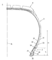
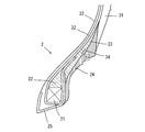
- FIG. 1 is a cross-sectional view showing a configuration of a pneumatic tire according to an embodiment of the present invention. It is a figure explaining the arrangement position of the electronic component in the Example of this invention. It is a figure explaining the arrangement position of the electronic component in the Example of this invention. It is a figure explaining the arrangement position of the electronic component in the Example of this invention. It is a figure explaining the arrangement position of the electronic component in the Example of this invention. It is a figure explaining the arrangement position of the electronic component in the Example of this invention. It is a figure explaining the arrangement position of the electronic component in the Example of this invention. It is a figure explaining the communication measurement point in the Example of this invention.
- the bead apex is made smaller, and instead, the bead reinforcing layer is disposed outside the end of the carcass ply to bring the electronic component close to the bead reinforcing layer, and the electronic between the bead reinforcing layer and the clinch I decided to provide parts.
- the clinch member has a lower rigidity than the bead reinforcing layer, and the electronic component is embedded between the bead reinforcing layer and the clinch member, as a result, the road surface It is possible to suppress breakage of the electronic component due to impact load or the like during traveling, and to provide a tire that does not cause deterioration in tire durability.
- FIG. 1 is a cross-sectional view showing the structure of a tire according to an embodiment of the present invention, and more specifically, a cross-sectional view of a tire of size 235 / 75R15.
- 1 is a tire
- 2 is a bead portion
- 3 is a sidewall portion
- 4 is a tread
- 21 is a bead core
- 22 is a bead apex
- 23 is a bead reinforcing layer
- 24 is a clinch member (hereinafter also referred to as "clinch").
- this clinch is an external member located inside tire radial direction rather than a sidewall, and located outside a bead reinforcement layer in a tire axial direction.
- 25 is a chafer.
- 31 is a sidewall
- 32 is a carcass ply
- 33 is an inner liner.
- Reference numeral 34 denotes an electronic component.
- H is the distance from the position of the tire maximum width to the bottom of the bead core
- L is the distance from the bottom of the bead core of the electronic component 34.
- the bead reinforcing layer 23 is disposed on the axially outer side (right side in FIG. 1) of the carcass ply 32 of the bead portion 2 to suppress deformation of the bead apex.
- the tire axial direction is a direction parallel to the rotation axis of the tire, and the tire axial direction outer side means that it is the outer side in the axial direction when a plane passing through the tire equator CL is the center.
- a clinch 24 is disposed adjacent to the bead reinforcement layer 23 on the axially outer side of the tire, and the electronic component 34 is embedded between the bead reinforcement layer 23 and the clinch 24.
- the electronic component 34 does not have to be directly adjacent to the bead reinforcing layer 23 and the clinch 24.
- the electronic component 34 may be coated with a rubber material other than the bead reinforcing layer 23 and the clinch 24. .
- the clinch 24 has lower rigidity than the bead reinforcing layer 23.
- the rigidity of the rubber is usually expressed by E * (complex elastic modulus) or the like, and the low rigidity means that the clinch 24 has a lower value of E * than the bead reinforcing layer 23.
- E * means an absolute value.
- E * at 70 ° C. of bead reinforcing layer 23 and clinch 24 is E * (1) MPa and E * (2) MPa, respectively, (E * (1) -E * (2)) It is preferable to satisfy the formula, more preferably 20 MPa or more, and further preferably 40 MPa or more. E * (1) -E * (2) ⁇ 5 MPa
- E * in the above is measured under the conditions shown below using a viscoelastic spectrometer (for example, "VESF-3” manufactured by Iwamoto Seisakusho Ltd.) in accordance with the provisions of "JIS K 6394".
- E * (1) at 70 ° C. of the rubber composition for bead reinforcing layer is, for example, 10 to 130 MPa
- E * (2) at 70 ° C. of the rubber composition for clinch is, for example, 7 It is ⁇ 80MPa.
- the steering of the vehicle is achieved.
- the impact on the electronic component can be mitigated to suppress the damage to the electronic component.
- tan ⁇ at 70 ° C. of the bead reinforcing layer 23 and the clinch 24 is tan ⁇ (1) and tan ⁇ (2), respectively (tan ⁇ (1) + tan ⁇ (2)) It is preferable to satisfy the formula, and more preferably 0.32 or less. tan ⁇ (1) + tan ⁇ (2) ⁇ 0.4
- tan ⁇ is a value measured in the same manner as the measurement of E * described above, and tan ⁇ (1) at 70 ° C. of the rubber composition for a bead reinforcing layer is, for example, 0.02 to 0.25. And the tan ⁇ (2) at 70 ° C. of the rubber composition for clinch is, for example, 0.02 to 0.29.
- the rubber composition for bead reinforcement layers of tandelta (1) of the range illustrated above the rubber composition for clinching of tandelta (2) which satisfies the above-mentioned formula is used.
- the rubber composition for bead reinforcing layer of tan ⁇ (1) satisfying the above formula is used.
- the electronic component is embedded in the tire according to the present embodiment.
- Specific electronic components include, for example, RFID, pressure sensor, temperature sensor, acceleration sensor, magnetic sensor, groove depth sensor, and the like.
- RFID can store and read non-contact information with a large volume of information, so it can store tire manufacturing information, management information, customer information, etc. in addition to data such as pressure and temperature. Particularly preferred.
- the electronic component 34 is embedded between the bead reinforcing layer 23 and the clinch 24.
- the specific embedding position is not particularly limited as long as reliable information communication is possible and the electronic component is not easily damaged by the deformation of the tire, but the damage of the electronic component by the deformation of the tire is relatively small.
- the distance from the position of the tire maximum width to the bottom of the bead core in the equatorial direction is outside the carcass axial end It is preferable to be disposed at a position where the height from the bottom of the bead core (L in FIG. 1) is 20 to 80% with respect to (H in FIG. 1).
- the size (long length including the IC chip and the antenna) of the electronic component to be embedded in the present embodiment is preferably 18 cm or less, more preferably 9 cm or less, and 4 cm or less. It is more preferable if it is present, and most preferably 2 cm or less. With such a small size, stress may be concentrated on the surrounding rubber, but in the present embodiment, as described above, consideration is given to local stress concentration. , The durability of the tire can be stably maintained. At this time, bending of the antenna portion can be kept to a minimum by arranging the antenna portion of the electronic component to extend in a direction orthogonal to the cord of the carcass.
- the rubber composition used for producing the bead reinforcing layer is mainly composed of a rubber component and a cured resin as a main component, a reinforcing material, and antiaging It can be obtained by kneading various compounding materials such as agents and additives.
- Rubber component As a rubber component, for example, natural rubber (NR), isoprene rubber (IR), butadiene rubber (BR), styrene butadiene rubber (SBR), acrylonitrile butadiene rubber (NBR), chloroprene rubber (CR), Mention may be made of diene rubbers such as butyl rubber (IIR). Among them, isoprene-based rubbers (NR and IR) are preferable from the viewpoint that steering stability, fuel economy and extrusion processability can be favorably improved.
- the content of the isoprene-based rubber is preferably 50 parts by mass or more, and more preferably 60 parts by mass or more in 100 parts by mass of the rubber component.
- (B) Cured resin It is preferable that a cured resin for enhancing the rigidity is blended in the rubber composition of the bead reinforcing layer. Although it does not specifically limit as hardening resin, A phenol-type resin is mentioned.
- phenolic resins include phenolic resins and modified phenolic resins.
- the phenolic resin is obtained by reacting phenol with an aldehyde such as formaldehyde, acetaldehyde, furfural or the like with an acid or an alkali catalyst, and the modified phenolic resin is cashew oil, tall oil, linseed oil, It is a phenolic resin modified with compounds such as various animal and vegetable oils, unsaturated fatty acids, rosins, alkylbenzene resins, aniline and melamine.
- the phenol resin is preferably a modified phenol resin, and more preferably a cashew oil modified phenol resin and a rosin modified phenol resin, from the viewpoint that a good hardness can be obtained by a curing reaction.
- the content of the cured resin in the rubber composition is preferably 5 parts by mass or more, and more preferably 10 parts by mass or more with respect to 100 parts by mass of the rubber component. Moreover, it is preferable that it is 25 mass parts or less, and it is more preferable in it being 20 mass parts or less.
- a curing agent having a curing action with the phenolic resin is not particularly limited as long as it has the above-mentioned curing action, and, for example, hexamethylenetetramine (HMT), hexamethoxymethylolmelamine (HMMM), hexamethoxymethylol pantamethylether (HMMPME), melamine And methylolmelamine.
- HMT, HMMM, and HMMPME are preferable from the viewpoint of being excellent in the action of increasing the hardness of the phenolic resin.
- the content of the curing agent is preferably 1 part by mass or more, and more preferably 5 parts by mass or more with respect to 100 parts by mass of the phenolic resin. If the amount is less than 1 part by mass, sufficient curing may not be possible. Moreover, it is preferable that it is 20 mass parts or less, and it is more preferable in it being 15 mass parts or less. If it exceeds 20 parts by mass, the curing may be uneven, and scorch may occur during extrusion.
- Carbon Black It is preferable to mix carbon black as a reinforcing material in the rubber composition of the present embodiment.
- carbon black include GPF, HAF, ISAF, SAF, FF, FEF and the like.
- One of these carbon blacks may be used alone, or two or more thereof may be used in combination.
- hard carbon-based ISAF, SAF, and HAF are preferable from the viewpoint of securing the hardness, and among them, HAF is particularly preferable.
- the content of carbon black in the rubber composition is preferably 30 parts by mass or more, and more preferably 45 parts by mass or more with respect to 100 parts by mass of the rubber component. Moreover, it is preferable that it is 70 mass parts or less, and it is more preferable in it being 65 mass parts or less.
- (D) Vulcanizing agent and vulcanization accelerator Sulfur is used as a vulcanizing agent, and its content is preferably 1 part by mass or more, and 2 parts by mass or more with respect to 100 parts by mass of the rubber component. And more preferred. Moreover, it is preferable that it is 8 mass parts or less, and it is more preferable in it being 6 mass parts or less.
- content of sulfur is pure sulfur content, and when using insoluble sulfur, it is content except oil content.
- Sulfur is usually used together with a vulcanization accelerator.
- the content of the vulcanization accelerator is preferably 1.5 parts by mass or more, and more preferably 2.0 parts by mass or more, with respect to 100 parts by mass of the rubber component. Moreover, it is preferable that it is 5.0 mass parts or less, and it is more preferable in it being 4.0 mass parts or less.
- Specific vulcanization accelerators include, for example, sulfenamide type, thiazole type, thiuram type, thiourea type, guanidine type, dithiocarbamic acid type, aldehyde-amine type or aldehyde-ammonia type, imidazoline type or xanthate type addition.
- a vulcanization accelerator etc. are mentioned.
- These vulcanization accelerators may be used alone or in combination of two or more.
- sulfenamide-based vulcanization accelerators are preferred because the scorch time and the vulcanization time can be balanced.
- Stearic acid As stearic acid, conventionally known products can be used. For example, products such as NOF Corporation, NOF, Kao Corporation, Wako Pure Chemical Industries, Ltd., Chiba Fatty Acid Corporation, etc. Can be used.
- the content of stearic acid is preferably 0.5 parts by mass or more, and more preferably 1 part by mass or more, with respect to 100 parts by mass of the rubber component. Moreover, it is preferable that it is 10 mass parts or less, and it is more preferable in it being 5 mass parts or less.
- (F) Zinc oxide As zinc oxide, conventionally known ones can be used. For example, Mitsui Mining & Smelting Co., Ltd., Toho Zinc Co., Ltd., Hax I Tech Co., Ltd., Shodo Chemical Industry Co., Ltd. You can use products such as When using zinc oxide, the content of zinc oxide is preferably 0.5 parts by mass or more, and more preferably 1 part by mass or more with respect to 100 parts by mass of the rubber component. Moreover, it is preferable that it is 10 mass parts or less, and it is more preferable in it being 5 mass parts or less. By setting the content of zinc oxide within the above range, the effects of the present invention tend to be obtained better.
- an amine-based anti-aging agent having an excellent ozone resistance effect is suitable.
- the amine-based anti-aging agent is not particularly limited, and examples thereof include amine derivatives such as diphenylamine-based, p-phenylenediamine-based, naphthylamine-based and ketone amine condensate-based ones, and these may be used alone. And two or more may be used in combination.
- diphenylamine derivatives examples include p- (p-toluenesulfonylamide) -diphenylamine, octylated diphenylamine, and 4,4′-bis ( ⁇ , ⁇ ′-dimethylbenzyl) diphenylamine.
- p-phenylenediamine derivatives include N- (1,3-dimethylbutyl) -N'-phenyl-p-phenylenediamine (6PPD), N-phenyl-N'-isopropyl-p-phenylenediamine (IPPD) And N, N'-di-2-naphthyl-p-phenylenediamine.
- naphthylamine derivatives examples include phenyl- ⁇ -naphthylamine and the like. Among them, phenylenediamine type and ketone amine condensate type are preferable.
- the content of the antiaging agent is preferably 0.3 parts by mass or more, and more preferably 0.5 parts by mass or more with respect to 100 parts by mass of the rubber component. Moreover, it is preferable that it is 8 mass parts or less, and it is more preferable in it being 2.5 mass parts or less.
- Waxes Waxes are not particularly limited, and petroleum waxes such as paraffin wax and microcrystalline wax; natural waxes such as plant wax and animal waxes; synthetic waxes such as polymers of ethylene and propylene etc. Can be mentioned. These may be used alone or in combination of two or more.
- a specific wax for example, products such as Ouchi Shinko Chemical Co., Ltd., Nippon Seiwa Co., Ltd., Seiko Kagaku Co., Ltd. can be used.
- the content of the wax is preferably 0.5 parts by mass or more, and more preferably 1 part by mass or more with respect to 100 parts by mass of the rubber component. Moreover, it is preferable that it is 10 mass parts or less, and it is more preferable in it being 7 mass parts or less.
- Oils Oils include, for example, process oils, vegetable oils and fats, or mixtures thereof.
- process oil for example, paraffin-based process oil, aroma-based process oil, naphthene-based process oil and the like can be used.
- Vegetable fats and oils include castor oil, cottonseed oil, linseed oil, rapeseed oil, palm oil, coconut oil, peanut oil, rosin, pine oil, pine tar, tall oil, corn oil, corn oil, vegetable oil, sesame oil, Olive oil, sunflower oil, palm kernel oil, soy sauce, jojoba oil, macadamia nut oil, soy sauce and the like can be mentioned. These may be used alone or in combination of two or more.
- oil examples include, for example, Idemitsu Kosan Co., Ltd., Sankyo Yuka Kogyo Co., Ltd., Japan Energy Co., Ltd., Japan Energy, Orisoi Company, H & R Company, Toyokuni Oil Co., Ltd., Showa Shell Sekiyu KK It is possible to use products such as Corporation.
- the content of oil is preferably 0.5 parts by mass or more, and more preferably 1 part by mass or more with respect to 100 parts by mass of the rubber component. Moreover, it is preferable that it is 10 mass parts or less, and it is more preferable in it being 5 mass parts or less.
- the rubber composition of the present embodiment also contains compounding materials conventionally used in the rubber industry, for example, inorganic fillers such as silica, talc and calcium carbonate, and organic materials such as cellulose fibers. Fillers, softeners such as liquid rubber and adhesive resins, vulcanizing agents other than sulfur, organic crosslinking agents, and the like may be added as needed. About the compounding quantity of each compounding material, it can select suitably.
- the bead reinforcing layer is preferably adjusted so that E * and tan ⁇ satisfy a predetermined relational expression with respect to the clinch.
- E * of a bead reinforcement layer the adjustment by increase and decrease of hardening resin is mentioned.
- E * can be increased by increasing the amount of the cured resin.
- E * can be adjusted by increasing or decreasing the amount of carbon black or sulfur.
- E * can be increased by increasing carbon black and sulfur.
- the amount of carbon black is increased, tan ⁇ is increased, and when the amount of sulfur is increased, tan ⁇ is decreased.
- the rubber composition of the clinch 24 is basically the same as the rubber composition used for the bead reinforcing layer 23, but the rubber composition of the clinch 24 is the rubber composition of the bead reinforcing layer
- the rigidity is adjusted to be lower than that of the object.
- the rubber component basically, the same rubber component as that of the bead reinforcing layer can be used.
- isoprene rubber (NR or IR) and BR can be used because good fuel economy and durability can be obtained. Combined use is more preferred.
- the content in 100 parts by mass of the rubber component is preferably 10 parts by mass or more, and more preferably 30 parts by mass or more. Moreover, it is preferable that it is 80 mass parts or less, and it is more preferable in it being 50 mass parts or less.
- the content in 100 parts by mass of the rubber component is preferably 20 parts by mass or more, and more preferably 50 parts by mass or more. Moreover, it is preferable that it is 90 mass parts or less, and it is more preferable in it being 70 mass parts or less.
- the BR is not particularly limited.
- BR having a high cis content BR having a high cis content, BR containing syndiotactic polybutadiene crystals (SPB-containing BR), modified BR, and the like can be used.
- SPB-containing BR is preferable from the viewpoint that extrusion processability can be greatly improved by the intrinsic orientation crystal component.
- the total content of isoprene rubber (NR or IR) and BR is preferably 80 parts by mass or more per 100 parts by mass of the rubber component, and more preferably 90 parts by mass or more preferable.
- the clinch is configured to be low in rigidity with respect to the bead reinforcing layer, and preferably adjusted so that E * and tan ⁇ satisfy the predetermined relational expression.
- E * of clinch although the same adjusting method as in the bead reinforcing layer can be mentioned, it is preferable to adjust the amount of carbon black or sulfur without using the cured resin as much as possible. That is, it is preferable to first adjust the amount of sulfur, then adjust the amount of carbon black, and finally adjust the amount of cured resin. This allows the aim E * and tan ⁇ to be achieved without the need for excessive trial and error.
- the rubber composition of the bead reinforcing layer and the clinch is obtained by kneading each of the above-mentioned components using, for example, a rubber kneading apparatus such as an open roll or a Banbury mixer. It can be manufactured.
- the tire according to the present embodiment can be manufactured by a usual method except for embedding an electronic component in the middle of molding. That is, the bead reinforcing layer 23 and the clinch 24 are formed by extrusion processing according to the shape of the bead apex at the unvulcanized stage of the rubber composition, and the other tire members are formed on the tire forming machine by the usual method. Paste together to form an unvulcanized tire. Then, in the middle of the molding, the electronic component is embedded at a predetermined position between the bead reinforcing layer and the clinch.
- a tire is manufactured by heating and pressing an unvulcanized tire in which electronic components are embedded and molded in a vulcanizer.
- Table 1 shows the ingredients and Table 2 and Table 3 show the ingredients.
- the unvulcanized rubber composition for clinch can be obtained.
- the rubber composition for electronic component 34 coating can be obtained.
- the obtained unvulcanized rubber composition is molded into the shape of a bead reinforcing layer or a clinch, respectively, and the unvulcanized rubber composition is laminated and bonded together with other tire members on a tire molding machine.
- the test tire (tyre size: 195 / 65R15) is obtained by setting the electronic component 34 coated in the above in any of FIG. 2A to FIG. 2E described later and vulcanizing under the condition of 150.degree. C. for 30 minutes. You can get it.
- the electronic component 34 an RFID in which a 30 mm antenna is provided on both sides of a 3 mm ⁇ 3 mm ⁇ 0.4 mm IC chip can be used.
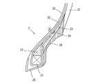
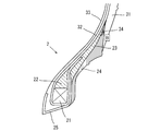
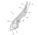
- FIGS. 2A to 2E Specific insertion positions of the electronic component 34 are shown in FIGS. 2A to 2E.
- the electronic component 34 is provided 31% below the bead core
- the electronic component 34 is provided 40% below the bead core
- the electronic component 34 is located 12% below the bead core.
- the electronic component 34 is provided at a position 29% from below the bead core in FIG. 2D
- the electronic component 34 is provided at a position 21% from below the bead core in FIG. 2E.
- these values are values with respect to the distance from the position of the tire maximum width to the bottom of the bead core.
- Tables 4 to 7 show the relationship between the composition and physical properties of the bead reinforcing layer and the clinch, the position of the electronic component, the durability of the tire, and the communication performance of the electronic component.
- the evaluation of the durability of the tire is acceptable if it can travel 10,000 km on a general road, and it is not acceptable if it can not.
- the mounting rim is 15 ⁇ 6.5 J
- the tire internal pressure is 230 kPa
- the test vehicle is a front wheel drive vehicle
- the displacement is 2000 cc
- the tire mounting position is all wheels.
- the evaluation method of communication property installs the transceiver for the electronic component at three measurement points (a to c) of the circle shown in FIG. 3 and judges whether it is possible to communicate data with the electronic component Do.
- the tire is assembled in a rim and mounted in a vehicle, and measured (the number of readable positions after the durability evaluation / the number of readable positions before the durability evaluation) is calculated.
- the average value of the tire is excellent if it is 60% or more, good if it is 50% or more and less than 60%, it is acceptable if it is more than 0% and less than 50%, 0% or readable position before durability evaluation If the number of is 0, it is not possible.
Landscapes
- Engineering & Computer Science (AREA)
- Mechanical Engineering (AREA)
- Tires In General (AREA)
Abstract
L'invention concerne un élément de fabrication de pneu dans lequel même lorsqu'un composant électronique est intégré dans un pneu, un endommagement dû à une charge d'impact pendant le déplacement sur la surface de la route est empêché et la durabilité du pneu ne se détériore pas. Un pneu comprend : une couche de renforcement de talon disposée sur le côté extérieur dans la direction axiale du pneu de la carcasse d'une partie de talon, la couche de renforcement de talon renforçant la partie de talon à partir du côté extérieur de la carcasse; un élément de rivetage disposé sur le côté extérieur de la direction axiale du pneu de la couche de renforcement de talon; et un dispositif électronique. L'élément de rivetage a une rigidité inférieure à celle de la couche de renforcement de talon, et le composant électronique est incorporé entre la couche de renforcement de talon et l'élément de rivetage.
Priority Applications (5)
| Application Number | Priority Date | Filing Date | Title |
|---|---|---|---|
| US16/641,732 US20200247193A1 (en) | 2017-09-12 | 2018-09-03 | Pneumatic tire |
| EP18857265.5A EP3677452B1 (fr) | 2017-09-12 | 2018-09-03 | Pneumatique |
| JP2019502038A JP6529701B1 (ja) | 2017-09-12 | 2018-09-03 | 空気入りタイヤ |
| CN201880058038.0A CN111051086B (zh) | 2017-09-12 | 2018-09-03 | 充气轮胎 |
| RU2020112013A RU2773733C2 (ru) | 2017-09-12 | 2018-09-03 | Пневматическая шина |
Applications Claiming Priority (2)
| Application Number | Priority Date | Filing Date | Title |
|---|---|---|---|
| JP2017175248 | 2017-09-12 | ||
| JP2017-175248 | 2017-09-12 |
Publications (1)
| Publication Number | Publication Date |
|---|---|
| WO2019054226A1 true WO2019054226A1 (fr) | 2019-03-21 |
Family
ID=65722772
Family Applications (1)
| Application Number | Title | Priority Date | Filing Date |
|---|---|---|---|
| PCT/JP2018/032660 WO2019054226A1 (fr) | 2017-09-12 | 2018-09-03 | Pneumatique |
Country Status (5)
| Country | Link |
|---|---|
| US (1) | US20200247193A1 (fr) |
| EP (1) | EP3677452B1 (fr) |
| JP (1) | JP6529701B1 (fr) |
| CN (1) | CN111051086B (fr) |
| WO (1) | WO2019054226A1 (fr) |
Cited By (23)
| Publication number | Priority date | Publication date | Assignee | Title |
|---|---|---|---|---|
| JP2019182395A (ja) * | 2018-04-03 | 2019-10-24 | ハンコック タイヤ アンド テクノロジー カンパニー リミテッドHankook Tire & Technology Co., Ltd. | 無線識別システムを含むタイヤ |
| JP2020055520A (ja) * | 2019-09-13 | 2020-04-09 | Toyo Tire株式会社 | タイヤおよびタイヤの製造方法 |
| CN111845214A (zh) * | 2019-04-24 | 2020-10-30 | 通伊欧轮胎株式会社 | 轮胎及轮胎的制造方法 |
| EP3760456A1 (fr) * | 2019-07-03 | 2021-01-06 | Continental Reifen Deutschland GmbH | Pneumatique |
| JP6819026B1 (ja) * | 2020-08-04 | 2021-01-27 | 住友ゴム工業株式会社 | 空気入りタイヤ |
| WO2021166792A1 (fr) * | 2020-02-17 | 2021-08-26 | 横浜ゴム株式会社 | Pneumatique |
| WO2021166793A1 (fr) * | 2020-02-17 | 2021-08-26 | 横浜ゴム株式会社 | Pneumatique |
| WO2021166795A1 (fr) * | 2020-02-17 | 2021-08-26 | 横浜ゴム株式会社 | Module rfid et pneu dans lequel celui-ci est intégré |
| WO2021166798A1 (fr) * | 2020-02-17 | 2021-08-26 | 横浜ゴム株式会社 | Bandage pneumatique |
| WO2022004478A1 (fr) * | 2020-06-29 | 2022-01-06 | 横浜ゴム株式会社 | Pneumatique |
| WO2022049915A1 (fr) * | 2020-09-01 | 2022-03-10 | 住友ゴム工業株式会社 | Pneumatique |
| JP7262564B1 (ja) | 2021-12-24 | 2023-04-21 | 横浜ゴム株式会社 | ソリッドタイヤ及びその製造方法 |
| JP7262563B1 (ja) | 2021-12-24 | 2023-04-21 | 横浜ゴム株式会社 | ソリッドタイヤ及びその製造方法 |
| WO2023105813A1 (fr) * | 2021-12-08 | 2023-06-15 | 株式会社ブリヂストン | Pneu |
| WO2023105814A1 (fr) * | 2021-12-08 | 2023-06-15 | 株式会社ブリヂストン | Pneumatique |
| US20230202244A1 (en) * | 2020-05-28 | 2023-06-29 | The Yokohama Rubber Co., Ltd. | Pneumatic tire |
| US20230264524A1 (en) * | 2020-06-29 | 2023-08-24 | The Yokohama Rubber Co., Ltd. | Pneumatic tire |
| US20230271459A1 (en) * | 2020-06-29 | 2023-08-31 | The Yokohama Rubber Co., Ltd. | Pneumatic tire |
| JP7343784B2 (ja) | 2020-02-17 | 2023-09-13 | 横浜ゴム株式会社 | 空気入りタイヤ |
| JP7343786B2 (ja) | 2020-02-17 | 2023-09-13 | 横浜ゴム株式会社 | 空気入りタイヤ |
| JP7343785B2 (ja) | 2020-02-17 | 2023-09-13 | 横浜ゴム株式会社 | 空気入りタイヤ |
| JP7469605B2 (ja) | 2020-02-17 | 2024-04-17 | 横浜ゴム株式会社 | 空気入りタイヤ |
| JP7469606B2 (ja) | 2020-02-17 | 2024-04-17 | 横浜ゴム株式会社 | 空気入りタイヤ |
Families Citing this family (12)
| Publication number | Priority date | Publication date | Assignee | Title |
|---|---|---|---|---|
| FR3059604A1 (fr) | 2016-12-05 | 2018-06-08 | Compagnie Generale Des Etablissements Michelin | Enveloppe pneumatique equipee d'un organe electronique |
| FR3059592A1 (fr) | 2016-12-05 | 2018-06-08 | Compagnie Generale Des Etablissements Michelin | Procede de fabrication d'un patch equipe d'un transpondeur radiofrequence et pneumatique comportant un tel patch |
| FR3059603A1 (fr) * | 2016-12-07 | 2018-06-08 | Compagnie Generale Des Etablissements Michelin | Pneumatique adapte pour roulage a plat equipe d’un organe electronique |
| JP6594509B1 (ja) | 2018-10-03 | 2019-10-23 | Toyo Tire株式会社 | タイヤおよびタイヤの製造方法 |
| JP7227847B2 (ja) * | 2019-05-17 | 2023-02-22 | Toyo Tire株式会社 | タイヤ |
| JP7401205B2 (ja) * | 2019-06-19 | 2023-12-19 | Toyo Tire株式会社 | タイヤ |
| JP2022014300A (ja) * | 2020-07-06 | 2022-01-19 | 住友ゴム工業株式会社 | 空気入りタイヤ |
| TWI759876B (zh) * | 2020-09-23 | 2022-04-01 | 正新橡膠工業股份有限公司 | 具有電子構件之輪胎 |
| JP2022070361A (ja) * | 2020-10-27 | 2022-05-13 | Toyo Tire株式会社 | タイヤ |
| JP2022081914A (ja) * | 2020-11-20 | 2022-06-01 | Toyo Tire株式会社 | タイヤ |
| JP2022081916A (ja) * | 2020-11-20 | 2022-06-01 | Toyo Tire株式会社 | タイヤ |
| JP7447938B2 (ja) * | 2022-06-24 | 2024-03-12 | 住友ゴム工業株式会社 | 重荷重用タイヤ |
Citations (11)
| Publication number | Priority date | Publication date | Assignee | Title |
|---|---|---|---|---|
| JP2000108619A (ja) * | 1998-10-01 | 2000-04-18 | Yokohama Rubber Co Ltd:The | タイヤ用トランスポンダの補助部品 |
| JP2006168473A (ja) | 2004-12-14 | 2006-06-29 | Sumitomo Rubber Ind Ltd | 電子部品の収納具を具える空気入りタイヤ、及びその製造方法 |
| JP2007049351A (ja) * | 2005-08-09 | 2007-02-22 | Yokohama Rubber Co Ltd:The | タイヤ用電子タグ及び空気入りタイヤ |
| JP2008265750A (ja) | 2007-04-03 | 2008-11-06 | Soc De Technol Michelin | 電子部材を有するタイヤ及びかかるタイヤの製造方法 |
| US20110175778A1 (en) * | 2008-09-25 | 2011-07-21 | Societe De Technologie Michelin | Tyre having a member with an offset antenna |
| JP2012086638A (ja) * | 2010-10-18 | 2012-05-10 | Bridgestone Corp | 重荷重用空気入りタイヤ |
| JP2013245339A (ja) | 2012-05-29 | 2013-12-09 | Sumitomo Rubber Ind Ltd | ケーストッピング用ゴム組成物及び空気入りタイヤ |
| JP2015098198A (ja) * | 2013-11-18 | 2015-05-28 | 住友ゴム工業株式会社 | 空気入りタイヤ |
| JP2016037235A (ja) * | 2014-08-08 | 2016-03-22 | 株式会社ブリヂストン | タイヤ |
| JP2016037236A (ja) * | 2014-08-08 | 2016-03-22 | 株式会社ブリヂストン | タイヤ |
| JP2016539047A (ja) * | 2013-12-13 | 2016-12-15 | ブリヂストン アメリカズ タイヤ オペレーションズ、 エルエルシー | 下部サイドウォール内に電子デバイスを有するタイヤ |
Family Cites Families (2)
| Publication number | Priority date | Publication date | Assignee | Title |
|---|---|---|---|---|
| EP1412207B1 (fr) * | 2001-07-19 | 2008-04-16 | Société de Technologie Michelin | Insert de roulage a plat pour pneumatiques |
| JP6013908B2 (ja) * | 2012-12-28 | 2016-10-25 | 住友ゴム工業株式会社 | 重荷重用タイヤ |
-
2018
- 2018-09-03 WO PCT/JP2018/032660 patent/WO2019054226A1/fr unknown
- 2018-09-03 EP EP18857265.5A patent/EP3677452B1/fr active Active
- 2018-09-03 JP JP2019502038A patent/JP6529701B1/ja active Active
- 2018-09-03 CN CN201880058038.0A patent/CN111051086B/zh active Active
- 2018-09-03 US US16/641,732 patent/US20200247193A1/en active Pending
Patent Citations (11)
| Publication number | Priority date | Publication date | Assignee | Title |
|---|---|---|---|---|
| JP2000108619A (ja) * | 1998-10-01 | 2000-04-18 | Yokohama Rubber Co Ltd:The | タイヤ用トランスポンダの補助部品 |
| JP2006168473A (ja) | 2004-12-14 | 2006-06-29 | Sumitomo Rubber Ind Ltd | 電子部品の収納具を具える空気入りタイヤ、及びその製造方法 |
| JP2007049351A (ja) * | 2005-08-09 | 2007-02-22 | Yokohama Rubber Co Ltd:The | タイヤ用電子タグ及び空気入りタイヤ |
| JP2008265750A (ja) | 2007-04-03 | 2008-11-06 | Soc De Technol Michelin | 電子部材を有するタイヤ及びかかるタイヤの製造方法 |
| US20110175778A1 (en) * | 2008-09-25 | 2011-07-21 | Societe De Technologie Michelin | Tyre having a member with an offset antenna |
| JP2012086638A (ja) * | 2010-10-18 | 2012-05-10 | Bridgestone Corp | 重荷重用空気入りタイヤ |
| JP2013245339A (ja) | 2012-05-29 | 2013-12-09 | Sumitomo Rubber Ind Ltd | ケーストッピング用ゴム組成物及び空気入りタイヤ |
| JP2015098198A (ja) * | 2013-11-18 | 2015-05-28 | 住友ゴム工業株式会社 | 空気入りタイヤ |
| JP2016539047A (ja) * | 2013-12-13 | 2016-12-15 | ブリヂストン アメリカズ タイヤ オペレーションズ、 エルエルシー | 下部サイドウォール内に電子デバイスを有するタイヤ |
| JP2016037235A (ja) * | 2014-08-08 | 2016-03-22 | 株式会社ブリヂストン | タイヤ |
| JP2016037236A (ja) * | 2014-08-08 | 2016-03-22 | 株式会社ブリヂストン | タイヤ |
Non-Patent Citations (1)
| Title |
|---|
| See also references of EP3677452A4 |
Cited By (37)
| Publication number | Priority date | Publication date | Assignee | Title |
|---|---|---|---|---|
| JP2019182395A (ja) * | 2018-04-03 | 2019-10-24 | ハンコック タイヤ アンド テクノロジー カンパニー リミテッドHankook Tire & Technology Co., Ltd. | 無線識別システムを含むタイヤ |
| US11059959B2 (en) | 2018-04-03 | 2021-07-13 | Hankook Tire Co., Ltd. | Tire including RFID system |
| CN111845214A (zh) * | 2019-04-24 | 2020-10-30 | 通伊欧轮胎株式会社 | 轮胎及轮胎的制造方法 |
| EP3760456A1 (fr) * | 2019-07-03 | 2021-01-06 | Continental Reifen Deutschland GmbH | Pneumatique |
| JP7222856B2 (ja) | 2019-09-13 | 2023-02-15 | Toyo Tire株式会社 | タイヤおよびタイヤの製造方法 |
| JP2020055520A (ja) * | 2019-09-13 | 2020-04-09 | Toyo Tire株式会社 | タイヤおよびタイヤの製造方法 |
| WO2021166795A1 (fr) * | 2020-02-17 | 2021-08-26 | 横浜ゴム株式会社 | Module rfid et pneu dans lequel celui-ci est intégré |
| WO2021166793A1 (fr) * | 2020-02-17 | 2021-08-26 | 横浜ゴム株式会社 | Pneumatique |
| WO2021166798A1 (fr) * | 2020-02-17 | 2021-08-26 | 横浜ゴム株式会社 | Bandage pneumatique |
| JP7469605B2 (ja) | 2020-02-17 | 2024-04-17 | 横浜ゴム株式会社 | 空気入りタイヤ |
| DE112021000288B4 (de) | 2020-02-17 | 2023-12-14 | The Yokohama Rubber Co., Ltd. | Luftreifen |
| JP7343785B2 (ja) | 2020-02-17 | 2023-09-13 | 横浜ゴム株式会社 | 空気入りタイヤ |
| JP7343786B2 (ja) | 2020-02-17 | 2023-09-13 | 横浜ゴム株式会社 | 空気入りタイヤ |
| JP7343784B2 (ja) | 2020-02-17 | 2023-09-13 | 横浜ゴム株式会社 | 空気入りタイヤ |
| CN115052759A (zh) * | 2020-02-17 | 2022-09-13 | 横滨橡胶株式会社 | 充气轮胎 |
| CN115103779A (zh) * | 2020-02-17 | 2022-09-23 | 横滨橡胶株式会社 | Rfid模块以及埋设有该rfid模块的充气轮胎 |
| WO2021166792A1 (fr) * | 2020-02-17 | 2021-08-26 | 横浜ゴム株式会社 | Pneumatique |
| JP7469606B2 (ja) | 2020-02-17 | 2024-04-17 | 横浜ゴム株式会社 | 空気入りタイヤ |
| US20230202244A1 (en) * | 2020-05-28 | 2023-06-29 | The Yokohama Rubber Co., Ltd. | Pneumatic tire |
| US20230264524A1 (en) * | 2020-06-29 | 2023-08-24 | The Yokohama Rubber Co., Ltd. | Pneumatic tire |
| US20230311589A1 (en) * | 2020-06-29 | 2023-10-05 | The Yokohama Rubber Co., Ltd. | Pneumatic tire |
| WO2022004478A1 (fr) * | 2020-06-29 | 2022-01-06 | 横浜ゴム株式会社 | Pneumatique |
| JP7457250B2 (ja) | 2020-06-29 | 2024-03-28 | 横浜ゴム株式会社 | 空気入りタイヤ |
| US20230271459A1 (en) * | 2020-06-29 | 2023-08-31 | The Yokohama Rubber Co., Ltd. | Pneumatic tire |
| JP2022029186A (ja) * | 2020-08-04 | 2022-02-17 | 住友ゴム工業株式会社 | 空気入りタイヤ |
| JP6819026B1 (ja) * | 2020-08-04 | 2021-01-27 | 住友ゴム工業株式会社 | 空気入りタイヤ |
| WO2022030285A1 (fr) * | 2020-08-04 | 2022-02-10 | 住友ゴム工業株式会社 | Bandage pneumatique |
| WO2022049915A1 (fr) * | 2020-09-01 | 2022-03-10 | 住友ゴム工業株式会社 | Pneumatique |
| JP2022041453A (ja) * | 2020-09-01 | 2022-03-11 | 住友ゴム工業株式会社 | 空気入りタイヤ |
| WO2023105813A1 (fr) * | 2021-12-08 | 2023-06-15 | 株式会社ブリヂストン | Pneu |
| WO2023105814A1 (fr) * | 2021-12-08 | 2023-06-15 | 株式会社ブリヂストン | Pneumatique |
| WO2023119941A1 (fr) * | 2021-12-24 | 2023-06-29 | 横浜ゴム株式会社 | Pneu plein et son procédé de fabrication |
| JP7262563B1 (ja) | 2021-12-24 | 2023-04-21 | 横浜ゴム株式会社 | ソリッドタイヤ及びその製造方法 |
| JP7262564B1 (ja) | 2021-12-24 | 2023-04-21 | 横浜ゴム株式会社 | ソリッドタイヤ及びその製造方法 |
| JP2023095093A (ja) * | 2021-12-24 | 2023-07-06 | 横浜ゴム株式会社 | ソリッドタイヤ及びその製造方法 |
| WO2023119942A1 (fr) * | 2021-12-24 | 2023-06-29 | 横浜ゴム株式会社 | Pneu plein et son procédé de fabrication |
| JP2023095092A (ja) * | 2021-12-24 | 2023-07-06 | 横浜ゴム株式会社 | ソリッドタイヤ及びその製造方法 |
Also Published As
| Publication number | Publication date |
|---|---|
| CN111051086A (zh) | 2020-04-21 |
| JPWO2019054226A1 (ja) | 2019-11-07 |
| EP3677452A1 (fr) | 2020-07-08 |
| CN111051086B (zh) | 2023-01-17 |
| US20200247193A1 (en) | 2020-08-06 |
| JP6529701B1 (ja) | 2019-06-12 |
| EP3677452B1 (fr) | 2023-04-19 |
| EP3677452A4 (fr) | 2021-08-18 |
| RU2020112013A (ru) | 2021-10-15 |
| RU2020112013A3 (fr) | 2021-12-17 |
Similar Documents
| Publication | Publication Date | Title |
|---|---|---|
| JP6529701B1 (ja) | 空気入りタイヤ | |
| JP6526935B1 (ja) | 空気入りタイヤ | |
| JP6529003B1 (ja) | 空気入りタイヤ | |
| JP6526936B1 (ja) | 空気入りタイヤ | |
| JP6529702B1 (ja) | 空気入りタイヤ | |
| JP6529002B1 (ja) | 空気入りタイヤ | |
| WO2019054227A1 (fr) | Pneumatique | |
| RU2773733C2 (ru) | Пневматическая шина | |
| RU2773734C2 (ru) | Пневматическая шина |
Legal Events
| Date | Code | Title | Description |
|---|---|---|---|
| ENP | Entry into the national phase |
Ref document number: 2019502038 Country of ref document: JP Kind code of ref document: A |
|
| 121 | Ep: the epo has been informed by wipo that ep was designated in this application |
Ref document number: 18857265 Country of ref document: EP Kind code of ref document: A1 |
|
| NENP | Non-entry into the national phase |
Ref country code: DE |
|
| ENP | Entry into the national phase |
Ref document number: 2018857265 Country of ref document: EP Effective date: 20200331 |