WO2019049222A1 - Mécanisme de restriction de direction d'ouverture/de fermeture pour dispositif d'obturation manuelle et mécanisme de restriction de direction d'ouverture/de fermeture pour porte coulissante suspendue - Google Patents
Mécanisme de restriction de direction d'ouverture/de fermeture pour dispositif d'obturation manuelle et mécanisme de restriction de direction d'ouverture/de fermeture pour porte coulissante suspendue Download PDFInfo
- Publication number
- WO2019049222A1 WO2019049222A1 PCT/JP2017/032022 JP2017032022W WO2019049222A1 WO 2019049222 A1 WO2019049222 A1 WO 2019049222A1 JP 2017032022 W JP2017032022 W JP 2017032022W WO 2019049222 A1 WO2019049222 A1 WO 2019049222A1
- Authority
- WO
- WIPO (PCT)
- Prior art keywords
- rotation
- opening
- door
- winding
- clutch
- Prior art date
Links
- 230000007246 mechanism Effects 0.000 title claims abstract description 63
- 238000004804 winding Methods 0.000 claims abstract description 120
- 230000000903 blocking effect Effects 0.000 claims description 22
- 230000001105 regulatory effect Effects 0.000 claims description 14
- 239000000725 suspension Substances 0.000 claims description 14
- 230000002265 prevention Effects 0.000 description 12
- 230000002457 bidirectional effect Effects 0.000 description 4
- 230000001133 acceleration Effects 0.000 description 2
- 239000000470 constituent Substances 0.000 description 2
- 238000010586 diagram Methods 0.000 description 2
- 230000000694 effects Effects 0.000 description 2
- 230000003028 elevating effect Effects 0.000 description 2
- 238000003780 insertion Methods 0.000 description 2
- 230000037431 insertion Effects 0.000 description 2
- 238000009434 installation Methods 0.000 description 2
- 238000000034 method Methods 0.000 description 2
- 230000008844 regulatory mechanism Effects 0.000 description 2
- 230000000630 rising effect Effects 0.000 description 2
- 238000006073 displacement reaction Methods 0.000 description 1
- 230000002572 peristaltic effect Effects 0.000 description 1
Images


Classifications
-
- E—FIXED CONSTRUCTIONS
- E06—DOORS, WINDOWS, SHUTTERS, OR ROLLER BLINDS IN GENERAL; LADDERS
- E06B—FIXED OR MOVABLE CLOSURES FOR OPENINGS IN BUILDINGS, VEHICLES, FENCES OR LIKE ENCLOSURES IN GENERAL, e.g. DOORS, WINDOWS, BLINDS, GATES
- E06B9/00—Screening or protective devices for wall or similar openings, with or without operating or securing mechanisms; Closures of similar construction
- E06B9/56—Operating, guiding or securing devices or arrangements for roll-type closures; Spring drums; Tape drums; Counterweighting arrangements therefor
- E06B9/60—Spring drums operated only by closure members
-
- E—FIXED CONSTRUCTIONS
- E06—DOORS, WINDOWS, SHUTTERS, OR ROLLER BLINDS IN GENERAL; LADDERS
- E06B—FIXED OR MOVABLE CLOSURES FOR OPENINGS IN BUILDINGS, VEHICLES, FENCES OR LIKE ENCLOSURES IN GENERAL, e.g. DOORS, WINDOWS, BLINDS, GATES
- E06B9/00—Screening or protective devices for wall or similar openings, with or without operating or securing mechanisms; Closures of similar construction
- E06B9/56—Operating, guiding or securing devices or arrangements for roll-type closures; Spring drums; Tape drums; Counterweighting arrangements therefor
- E06B9/80—Safety measures against dropping or unauthorised opening; Braking or immobilising devices; Devices for limiting unrolling
-
- E—FIXED CONSTRUCTIONS
- E05—LOCKS; KEYS; WINDOW OR DOOR FITTINGS; SAFES
- E05D—HINGES OR SUSPENSION DEVICES FOR DOORS, WINDOWS OR WINGS
- E05D13/00—Accessories for sliding or lifting wings, e.g. pulleys, safety catches
- E05D13/10—Counterbalance devices
- E05D13/12—Counterbalance devices with springs
- E05D13/1253—Counterbalance devices with springs with canted-coil torsion springs
- E05D13/1261—Counterbalance devices with springs with canted-coil torsion springs specially adapted for overhead wings
-
- E—FIXED CONSTRUCTIONS
- E05—LOCKS; KEYS; WINDOW OR DOOR FITTINGS; SAFES
- E05D—HINGES OR SUSPENSION DEVICES FOR DOORS, WINDOWS OR WINGS
- E05D13/00—Accessories for sliding or lifting wings, e.g. pulleys, safety catches
- E05D13/10—Counterbalance devices
- E05D13/12—Counterbalance devices with springs
- E05D13/1276—Counterbalance devices with springs with coiled ribbon springs, e.g. constant force springs
- E05D13/1284—Counterbalance devices with springs with coiled ribbon springs, e.g. constant force springs specially adapted for overhead wings
-
- E—FIXED CONSTRUCTIONS
- E05—LOCKS; KEYS; WINDOW OR DOOR FITTINGS; SAFES
- E05F—DEVICES FOR MOVING WINGS INTO OPEN OR CLOSED POSITION; CHECKS FOR WINGS; WING FITTINGS NOT OTHERWISE PROVIDED FOR, CONCERNED WITH THE FUNCTIONING OF THE WING
- E05F1/00—Closers or openers for wings, not otherwise provided for in this subclass
- E05F1/08—Closers or openers for wings, not otherwise provided for in this subclass spring-actuated, e.g. for horizontally sliding wings
- E05F1/16—Closers or openers for wings, not otherwise provided for in this subclass spring-actuated, e.g. for horizontally sliding wings for sliding wings
-
- E—FIXED CONSTRUCTIONS
- E05—LOCKS; KEYS; WINDOW OR DOOR FITTINGS; SAFES
- E05F—DEVICES FOR MOVING WINGS INTO OPEN OR CLOSED POSITION; CHECKS FOR WINGS; WING FITTINGS NOT OTHERWISE PROVIDED FOR, CONCERNED WITH THE FUNCTIONING OF THE WING
- E05F5/00—Braking devices, e.g. checks; Stops; Buffers
- E05F5/003—Braking devices, e.g. checks; Stops; Buffers for sliding wings
-
- E—FIXED CONSTRUCTIONS
- E06—DOORS, WINDOWS, SHUTTERS, OR ROLLER BLINDS IN GENERAL; LADDERS
- E06B—FIXED OR MOVABLE CLOSURES FOR OPENINGS IN BUILDINGS, VEHICLES, FENCES OR LIKE ENCLOSURES IN GENERAL, e.g. DOORS, WINDOWS, BLINDS, GATES
- E06B3/00—Window sashes, door leaves, or like elements for closing wall or like openings; Layout of fixed or moving closures, e.g. windows in wall or like openings; Features of rigidly-mounted outer frames relating to the mounting of wing frames
- E06B3/32—Arrangements of wings characterised by the manner of movement; Arrangements of movable wings in openings; Features of wings or frames relating solely to the manner of movement of the wing
- E06B3/34—Arrangements of wings characterised by the manner of movement; Arrangements of movable wings in openings; Features of wings or frames relating solely to the manner of movement of the wing with only one kind of movement
- E06B3/42—Sliding wings; Details of frames with respect to guiding
- E06B3/46—Horizontally-sliding wings
-
- E—FIXED CONSTRUCTIONS
- E06—DOORS, WINDOWS, SHUTTERS, OR ROLLER BLINDS IN GENERAL; LADDERS
- E06B—FIXED OR MOVABLE CLOSURES FOR OPENINGS IN BUILDINGS, VEHICLES, FENCES OR LIKE ENCLOSURES IN GENERAL, e.g. DOORS, WINDOWS, BLINDS, GATES
- E06B9/00—Screening or protective devices for wall or similar openings, with or without operating or securing mechanisms; Closures of similar construction
- E06B9/02—Shutters, movable grilles, or other safety closing devices, e.g. against burglary
- E06B9/04—Shutters, movable grilles, or other safety closing devices, e.g. against burglary of wing type, e.g. revolving or sliding
-
- E—FIXED CONSTRUCTIONS
- E06—DOORS, WINDOWS, SHUTTERS, OR ROLLER BLINDS IN GENERAL; LADDERS
- E06B—FIXED OR MOVABLE CLOSURES FOR OPENINGS IN BUILDINGS, VEHICLES, FENCES OR LIKE ENCLOSURES IN GENERAL, e.g. DOORS, WINDOWS, BLINDS, GATES
- E06B9/00—Screening or protective devices for wall or similar openings, with or without operating or securing mechanisms; Closures of similar construction
- E06B9/02—Shutters, movable grilles, or other safety closing devices, e.g. against burglary
- E06B9/08—Roll-type closures
-
- E—FIXED CONSTRUCTIONS
- E06—DOORS, WINDOWS, SHUTTERS, OR ROLLER BLINDS IN GENERAL; LADDERS
- E06B—FIXED OR MOVABLE CLOSURES FOR OPENINGS IN BUILDINGS, VEHICLES, FENCES OR LIKE ENCLOSURES IN GENERAL, e.g. DOORS, WINDOWS, BLINDS, GATES
- E06B9/00—Screening or protective devices for wall or similar openings, with or without operating or securing mechanisms; Closures of similar construction
- E06B9/56—Operating, guiding or securing devices or arrangements for roll-type closures; Spring drums; Tape drums; Counterweighting arrangements therefor
- E06B9/80—Safety measures against dropping or unauthorised opening; Braking or immobilising devices; Devices for limiting unrolling
- E06B9/82—Safety measures against dropping or unauthorised opening; Braking or immobilising devices; Devices for limiting unrolling automatic
- E06B9/90—Safety measures against dropping or unauthorised opening; Braking or immobilising devices; Devices for limiting unrolling automatic for immobilising the closure member in various chosen positions
-
- E—FIXED CONSTRUCTIONS
- E05—LOCKS; KEYS; WINDOW OR DOOR FITTINGS; SAFES
- E05Y—INDEXING SCHEME ASSOCIATED WITH SUBCLASSES E05D AND E05F, RELATING TO CONSTRUCTION ELEMENTS, ELECTRIC CONTROL, POWER SUPPLY, POWER SIGNAL OR TRANSMISSION, USER INTERFACES, MOUNTING OR COUPLING, DETAILS, ACCESSORIES, AUXILIARY OPERATIONS NOT OTHERWISE PROVIDED FOR, APPLICATION THEREOF
- E05Y2201/00—Constructional elements; Accessories therefor
- E05Y2201/20—Brakes; Disengaging means; Holders; Stops; Valves; Accessories therefor
- E05Y2201/214—Disengaging means
- E05Y2201/216—Clutches
-
- E—FIXED CONSTRUCTIONS
- E05—LOCKS; KEYS; WINDOW OR DOOR FITTINGS; SAFES
- E05Y—INDEXING SCHEME ASSOCIATED WITH SUBCLASSES E05D AND E05F, RELATING TO CONSTRUCTION ELEMENTS, ELECTRIC CONTROL, POWER SUPPLY, POWER SIGNAL OR TRANSMISSION, USER INTERFACES, MOUNTING OR COUPLING, DETAILS, ACCESSORIES, AUXILIARY OPERATIONS NOT OTHERWISE PROVIDED FOR, APPLICATION THEREOF
- E05Y2201/00—Constructional elements; Accessories therefor
- E05Y2201/60—Suspension or transmission members; Accessories therefor
- E05Y2201/622—Suspension or transmission members elements
- E05Y2201/71—Toothed gearing
- E05Y2201/72—Planetary gearing
-
- E—FIXED CONSTRUCTIONS
- E05—LOCKS; KEYS; WINDOW OR DOOR FITTINGS; SAFES
- E05Y—INDEXING SCHEME ASSOCIATED WITH SUBCLASSES E05D AND E05F, RELATING TO CONSTRUCTION ELEMENTS, ELECTRIC CONTROL, POWER SUPPLY, POWER SIGNAL OR TRANSMISSION, USER INTERFACES, MOUNTING OR COUPLING, DETAILS, ACCESSORIES, AUXILIARY OPERATIONS NOT OTHERWISE PROVIDED FOR, APPLICATION THEREOF
- E05Y2201/00—Constructional elements; Accessories therefor
- E05Y2201/60—Suspension or transmission members; Accessories therefor
- E05Y2201/622—Suspension or transmission members elements
- E05Y2201/71—Toothed gearing
- E05Y2201/722—Racks
-
- E—FIXED CONSTRUCTIONS
- E05—LOCKS; KEYS; WINDOW OR DOOR FITTINGS; SAFES
- E05Y—INDEXING SCHEME ASSOCIATED WITH SUBCLASSES E05D AND E05F, RELATING TO CONSTRUCTION ELEMENTS, ELECTRIC CONTROL, POWER SUPPLY, POWER SIGNAL OR TRANSMISSION, USER INTERFACES, MOUNTING OR COUPLING, DETAILS, ACCESSORIES, AUXILIARY OPERATIONS NOT OTHERWISE PROVIDED FOR, APPLICATION THEREOF
- E05Y2900/00—Application of doors, windows, wings or fittings thereof
- E05Y2900/10—Application of doors, windows, wings or fittings thereof for buildings or parts thereof
- E05Y2900/13—Type of wing
- E05Y2900/132—Doors
-
- E—FIXED CONSTRUCTIONS
- E05—LOCKS; KEYS; WINDOW OR DOOR FITTINGS; SAFES
- E05Y—INDEXING SCHEME ASSOCIATED WITH SUBCLASSES E05D AND E05F, RELATING TO CONSTRUCTION ELEMENTS, ELECTRIC CONTROL, POWER SUPPLY, POWER SIGNAL OR TRANSMISSION, USER INTERFACES, MOUNTING OR COUPLING, DETAILS, ACCESSORIES, AUXILIARY OPERATIONS NOT OTHERWISE PROVIDED FOR, APPLICATION THEREOF
- E05Y2900/00—Application of doors, windows, wings or fittings thereof
- E05Y2900/10—Application of doors, windows, wings or fittings thereof for buildings or parts thereof
- E05Y2900/13—Type of wing
- E05Y2900/146—Shutters
-
- E—FIXED CONSTRUCTIONS
- E06—DOORS, WINDOWS, SHUTTERS, OR ROLLER BLINDS IN GENERAL; LADDERS
- E06B—FIXED OR MOVABLE CLOSURES FOR OPENINGS IN BUILDINGS, VEHICLES, FENCES OR LIKE ENCLOSURES IN GENERAL, e.g. DOORS, WINDOWS, BLINDS, GATES
- E06B9/00—Screening or protective devices for wall or similar openings, with or without operating or securing mechanisms; Closures of similar construction
- E06B9/56—Operating, guiding or securing devices or arrangements for roll-type closures; Spring drums; Tape drums; Counterweighting arrangements therefor
- E06B9/80—Safety measures against dropping or unauthorised opening; Braking or immobilising devices; Devices for limiting unrolling
- E06B2009/801—Locking arrangements
Definitions
- the present invention relates to an open / close direction restricting mechanism for restricting the rotational direction of a winding member used in a manual shutter device in which a rotationally driven winding member raises and lowers a slat, and a hanging sliding door in which a hanging sliding door is suspended from a hanging rail
- the present invention relates to an open / close direction restricting mechanism that restricts the sliding direction of a hanging sliding door used in the device.
- Patent Document 1 relating to an electric shutter discloses that a slat is wound around a winding shaft by an electric motor rotationally driving a winding shaft. The rotation of the winding shaft is controlled by the rotation direction and ON / OFF of the electric motor input via the operation switch, and the slat is stopped at an arbitrary position.
- Patent Document 2 relating to a manual shutter discloses that a torsion spring wound around a fixed shaft applies a torque in a winding direction in which a slat is wound on a winding shaft. As a result, when the user slightly lifts the slat, the torque of the torsion spring causes all the slats to be rolled up.
- Patent Document 3 relating to the sliding door apparatus, a pinion directly connected to the output shaft of the electric motor meshes with a rack provided on the upper side surface of the door, and when the electric motor is driven and the pinion rotates forward, the door There is disclosed an automatic opening / closing device of a sliding door which moves in the opening direction and the door moves in the closing direction when the pinion reversely rotates.
- JP, 2010-24752 A JP-A-5-93487 Japanese Patent Application Laid-Open No. 11-280336
- the slat can be stopped at any position, since it is possible to select either the fully open state in which all the slats are wound up or the fully closed state in which all the slats are lowered. There is a problem that the slat has to be raised and lowered unnecessarily.
- the present invention is proposed to achieve the above object, and the invention according to the first aspect comprises a fixed shaft extending substantially horizontally and a rotary shaft rotatably provided on the fixed shaft to take up a slat.
- the winding direction control mechanism of a manual shutter device comprising: a winding member; and a torsion spring which is incorporated in the winding member and biases the winding member in a winding direction for winding the slat.
- a two-way clutch disposed, wherein the gear formed on the flange and the clutch external gear mounted on the input shaft of the two-way clutch can be engaged with each other
- the two-way clutch allows rotation of the clutch external gear along the winding direction of the winding member and prevents rotation of the clutch external gear along the reverse winding direction. And a forward rotation blocking state in which rotation of the clutch external gear along the winding direction of the winding member is blocked and rotation of the clutch external gear along the reverse winding direction is permitted.
- an open / close direction regulating mechanism for a manual shutter device is provided.
- the external gear for the clutch is rotated about the input shaft by applying an external force to the take-up member in the direction in which the two-way clutch permits rotation, and the take-up member and the take-up member
- the slats can be raised and lowered as the brackets or flanges mounted on the slats rotate about a fixed axis.
- the clutch external gear is prevented from rotating around the input shaft, and the winding member and the winding Since the rotation of the bracket or flange attached to the member is prevented around the fixed axis, the slat is prevented from moving up and down.
- the slat may be either rising or falling , You can stop the slat.
- the bracket is formed in a tubular shape, externally fitted to the fixed shaft, and rotatably provided integrally with the winding member.
- the flange provides an open / close direction control mechanism of the manual shutter device fixed to the fixed shaft.
- opening and closing of the manual shutter device is an internal gear formed on an opposing surface of the flange facing the bracket. Provide a direction control mechanism.
- the clutch external gear meshes with the internal gear and revolves around the fixed shaft, and the take-up member
- the slat can be raised and lowered to rotate around a fixed axis.
- the clutch external gear is prevented from revolving around the fixed shaft, and rotation of the winding member around the fixed shaft Of the slat is prevented because the
- a rotation damper provided on an opposing surface of the bracket and having a damper external gear meshable with the gear.
- An open / close direction regulating mechanism of a manual shutter device is provided.
- the rotation damper can quietly raise and lower the slat in order to brake the rotation of the winding member input to the rotation damper via the flange and the damper external gear.
- the rotation damper is an infinite-angle rotation damper that decelerates the winding member when the winding member rotates in the winding direction.
- an open / close direction regulation mechanism of a manual shutter device is provided.
- the rotation damper suppresses the rotation of the winding member by braking the rotation of the winding member when the slat rises, thereby preventing the winding member from excessively accelerating and rotating in the winding direction. It can be raised quietly and safely.
- the two-way clutch and the rotary damper are disposed concentrically around the fixed axis. Provide an open / close direction control mechanism.
- the clutch external gear of the two-way clutch and the damper external gear of the rotational damper interlock with each other through the gear of the flange, so that the opening / closing direction restriction mechanism can be installed in a space-saving manner.
- the invention according to claim 7 is the opening / closing direction restricting mechanism of the hanging sliding door apparatus having the hanging sliding door suspended from the hanging rail provided substantially horizontally and providing the hanging sliding door with a liner capable of traveling on the hanging rail.
- a base member is fixed to the upper end of the hanging door, and a two-way clutch is disposed on an opposite surface of the base member facing the hanging rail, and a rack formed on the hanging rail and an input shaft of the two-way clutch
- the two-way clutch allows rotation of the clutch pinion in accordance with the sliding of the hanging door in the closing direction, and the two-way clutch allows rotation of the hanging door in the opening direction.
- the suspension is performed by blocking the rotation of the clutch pinion in response to the opening of the clutch pinion in response to the slide and the sliding of the suspension door in the closing direction.
- Providing an opening and closing direction regulating mechanism of the sliding door device suspended provided a closed blocking state to allow sliding rotation of the pinion clutch in accordance with to the door open direction switchable.
- an external force is applied to the hanging and sliding door in the direction in which the two-way clutch permits rotation, whereby the clutch pinion for the two-way clutch engages with the rack of the hanging rail and proceeds. It can be opened and closed.
- the clutch pinion for the two-way clutch engages with the rack of the hanging rail and proceeds. It can be opened and closed.
- rotation of the clutch pinion is blocked and relative sliding of the hanging and sliding door with respect to the suspension rail is blocked. , Sliding sliding door is hindered.
- the rotation direction of the clutch pinion permitted by the 2-way clutch that is, the open blocking state and the closed blocking state of the 2-way clutch can be arbitrarily switched, either during the opening operation or closing operation of the hanging door Also, the sliding door can be stopped.
- a suspension including a damper pinion capable of meshing with the rack, and a rotation damper provided on the opposite surface of the base member Provided is a mechanism for restricting the opening and closing direction of a sliding door device.
- the rotation damper brakes the slide of the base member and the hanging and sliding door input to the rotating damper via the suspension rail and the damper pinion, the hanging and sliding door can be opened and closed quietly.
- the swing sliding door is an infinite-angle rotary damper which decelerates the swing sliding door when the swing sliding door slides in a closing direction. To provide a mechanism for restricting the opening and closing direction of the device.
- the rotation damper suppresses the excessive acceleration of the hanging door in the closing direction by braking the sliding door during the closing movement of the hanging door, thereby making the hanging door quiet and safe. Can be closed.
- the external gear for the clutch is rotated about the input shaft by applying an external force to the take-up member in the direction in which the two-way clutch permits rotation. Since the winding member and the bracket or flange attached to the winding member rotate around a fixed axis, the slat can be raised and lowered. On the other hand, when an external force is applied to the winding member in the direction in which the two-way clutch blocks the rotation, the clutch external gear is prevented from rotating around the input shaft, and the winding member and the winding Since the rotation of the bracket or flange attached to the member is prevented around the fixed axis, the slat is prevented from moving up and down.
- the slat may be either rising or falling , You can stop the slat.
- the clutch pinion of the two way clutch is the rack of the hanging rail by applying an external force to the hanging and sliding door in the direction in which the two way clutch permits rotation.
- the sliding door can be opened and closed in order to engage with it.
- external force is applied to the hanging and sliding door in the direction in which the two-way clutch blocks rotation
- rotation of the clutch pinion is blocked and relative sliding of the hanging and sliding door with respect to the suspension rail is blocked.
- Sliding sliding door is hindered.
- the allowable rotation direction of the clutch pinion that is, the open blocking state and the closed blocking state of the two-way clutch can be arbitrarily switched, the hanging and pulling door can be switched either during opening or closing Can be stopped.
- FIG. 3 The partially cutaway front view which shows the manual type shutter apparatus which applied the opening / closing direction control mechanism which concerns on one Example of this invention.
- AA partially omitted sectional drawing of FIG. FIG. 3 is a left side view showing the flange of FIG. 2; The right side view which shows the bracket of FIG. 2, a 2 way clutch, and a rotation damper.
- the partially notched front view which shows the lifting sliding door apparatus to which the opening / closing direction control mechanism which concerns on one Example of this invention is applied.
- the opening / closing direction restricting mechanism of the manual shutter device extends approximately horizontally to provide a mechanism for positioning the winding member rotating relative to the fixed shaft at a desired position at low cost.
- An opening / closing direction control mechanism of a manual shutter device comprising a torsion spring, a bracket attached to one of a winding member or a fixed shaft, and a bracket disposed adjacent to the bracket and attached to the other of the winding member or the fixed shaft
- a two-way clutch disposed on the opposite surface facing the flange of the bracket, and mounted on the gear formed on the flange and the input shaft of the two-way clutch
- the two-way clutch allows rotation of the clutch external gear along the winding direction of the take-up member, and allows the clutch external gear to rotate in the reverse winding direction. Reverse
- the opening and closing direction regulating mechanism of the hanging and sliding door is a hanging rail provided substantially horizontally to provide a mechanism for positioning the hanging and sliding door relative to the hanging rail at a desired position at low cost.
- the base member is fixed to the upper end of the hanging door in the opening / closing direction regulating mechanism of the hanging door device configured to hang the hanging door on the hanging door and provide the liner capable of traveling on the hanging rail on the hanging door.
- a two-way clutch is disposed on the opposite surface facing each other, and the rack formed on the suspension rail and the pinion for the clutch mounted on the input shaft of the two-way clutch can be engaged so that the two-way clutch An open blocking state for permitting rotation of the clutch pinion in response to sliding in the direction and blocking rotation of the clutch pinion in response to sliding in the opening direction of the hanging door; It is possible to prevent switching of the clutch pinion from rotating in response to sliding in the direction, and switch to a closed blocking state that allows rotation of the clutch pinion in response to sliding of the hanging door in the opening direction. did.
- FIG. 1 is a partially cutaway front view showing a manual shutter device 1 to which the open / close direction restricting mechanism 10 is applied.
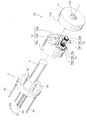
- FIG. 2 is an exploded perspective view showing the open / close direction restricting mechanism 10.
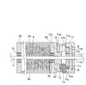
- FIG. 3 is a partially omitted sectional view taken along line AA of FIG.
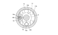
- FIG. 4 is a left side view showing the flange 11 of FIG.
- FIG. 5 is a right side view showing the bracket 12, the two-way clutch 13 and the rotation damper 14 of FIG. 6 is a cross-sectional view taken along the line BB in FIG.
- the shutter device 1 vertically opens and closes an opening of a large area such as a garage or a store.
- the shutter device 1 includes a slat 2 capable of moving up and down, a winding member 3 for winding the slat 2, and a fixed shaft 4 disposed at the rotational center of the winding member 3.
- a housing space 5 for housing the slat 2, the winding member 3 and the fixed shaft 4 is covered with a housing cover 5 a and protected without being exposed to wind and rain.
- the slat member 2 is configured such that slat members 2a disposed adjacent to each other vertically are hinged via a peristaltic shaft 2b.
- the upper end of the slat 2 is coupled to the winding member 3 and is configured to be wound around the outer periphery of the winding member 3. Both ends of the slat 2 are accommodated in sliding grooves (not shown) of the guide rails 6 erected on the left and right, so that fluttering caused by the elevation of the slat 2 is suppressed.
- the winding member 3 is formed in a substantially cylindrical shape. Specifically, the winding member 3 is joined to one end of four shafts 3a horizontally extended, bearings 3b and 3c press-fit fitted to the fixed shaft 4, and one end of the shaft 3a It comprises a wheel 3d which is externally fitted to 3b, and a wheel 3e which is joined to the other end of the shaft 3a and which is externally fitted to a bearing 3c.
- the winding member 3 is rotationally driven in the winding direction (opening direction) D1
- the slat 2 is taken up by the winding member 3 and ascends
- the winding member 3 is in the reverse winding direction (closing direction )
- the number of shafts 3a is not limited to four, and may be two to three or five or more.
- the fixed shaft 4 is bridged between the shutter brackets 7 respectively provided on the upper portions of the left and right guide rails 6, and both ends of the fixed shaft 4 are fixedly supported by the shutter bracket 7, respectively.
- a torsion spring (torsion coil spring) 8 is wound around the fixed shaft 4.
- the torsion spring 8 is accommodated in the winding member 3. One end of the torsion spring 8 is fixed to the wheel 3 d, and the other end is fixed to the fixed shaft 4. The torsion spring 8 biases the wheel 3d in the winding direction D1. Thereby, the slat 2 can be lifted with a slight force.
- the opening / closing direction restricting mechanism 10 includes a flange 11 fixed to an end of the fixed shaft 4, a bracket 12 disposed adjacent to the flange 11, and a two-way clutch 13 provided on the side surface of the bracket 12. ing.
- An internal gear 11 b is formed on the facing surface 11 a of the flange 11 facing the bracket 12.
- the flange 11 is formed in a disk shape, and the tip of the bolt B screwed into the bolt hole 11 c bites into the fixed shaft 4 so that the flange 11 is fixed to the fixed shaft 4.
- Reference numeral 11 d denotes an insertion hole through which the fixed shaft 4 is inserted.
- the bracket 12 is formed in a cylindrical shape, and a small diameter portion 3d 'of the wheel 3d is inserted through the central hole 12a.
- a two-way clutch 13 is provided on one side 12 b opposite to the flange 11 of the bracket 12.
- the other side 12 c of the bracket 12 is joined to the wheel 3 d. Accordingly, the bracket 12 is configured to rotate integrally with the winding member 3 via the wheel 3d.
- a clutch planet external gear 13 b is provided on the input shaft 13 a of the two-way clutch 13.
- the clutch planet external gear 13 b can be engaged with the internal gear 11 b of the flange 11.
- the bracket 12 is driven to rotate relative to the flange 11, the internal gear 11b of the flange 11 and the clutch planetary external gear 13b of the two-way clutch 13 mesh, and the input shaft 13a of the two-way clutch 13 rotates. .
- the two-way clutch 13 has a known configuration, and either rotation (forward rotation) along the winding direction D1 of the winding member 3 or rotation (reverse rotation) along the reverse winding direction D2 of the winding member 3 It allows one and limits the other.
- the rotation direction (locking direction) restricted by the two-way clutch 13 can be arbitrarily switched by applying an external force equal to or greater than a predetermined threshold value in the direction in which the rotation is already restricted.
- a friction switching type or an electrical switching type is known as a driving method of the two-way clutch 13, and either of the present invention may be adopted. The former can be introduced at low cost.
- the opening / closing direction control mechanism 10 further includes a rotation damper 14.
- the rotation damper 14 is provided on one side surface 12 b of the bracket 12.
- a damper planetary outer gear 14 b capable of meshing with the internal gear 11 b of the flange 11 is provided on the input shaft 14 a of the rotary damper 14.
- the rotation damper 14 has a known configuration, and brakes the rotational movement of the input shaft 14a input through the damper planetary outer gear 14b.
- the rotation damper 14 is, for example, an oil damper or the like that brakes the rotation of the input shaft 14 a with viscous resistance of oil.
- the rotation damper 14 is preferably an infinite rotation damper which decelerates the winding member 3 at least when the winding member 3 rotates in the winding direction D1.
- a bidirectional infinite rotation damper is adopted as the rotation damper 14
- the raising and lowering of the slat 2 is braked and the slat 2 is raised and lowered gently.
- a one-way infinite rotation damper is adopted as the rotation damper 14
- the rise of the slat 2 is braked, and the slat 2 is gently raised while the force for braking the descent of the slat 2 when lowering the slat 2 ( Since no damper force is applied, it can be operated with a light force.
- the two-way clutch 13 and the rotary damper 14 are disposed concentrically around the fixed shaft 4 as viewed from the axial direction of the fixed shaft 4.
- the number of installed rotary dampers 14 provided in the opening / closing direction regulating mechanism 10 is not limited to one, and may be two or more. When two rotational dampers 14 are provided, it is preferable that the rotational dampers 14 be disposed so as to sandwich the two-way clutch 13.
- the side surface 13 c of the two-way clutch 13 and the side surface 14 c of the rotary damper 14 are substantially flush with each other when viewed from the radial direction of the fixed shaft 4.
- 12 can rotate at a substantially constant position with respect to the flange 11.
- the opening / closing direction restricting mechanism 10 is not limited to the above-described configuration, and for example, the flange 11 can be integrally provided integrally with the winding member 3 and the bracket 12 is fixed to the fixed shaft 4 It does not matter. Further, an external gear (not shown) may be engraved on the outer periphery of the bracket 12 instead of the internal gear 11b, and this external gear may be engaged with the clutch planetary external gear 13b and the damper planetary external gear 14b. Absent.
- 7 (a) to 7 (d) are partially cutaway front views showing the operation of the opening / closing direction control mechanism 10.
- FIG. In the following, the case where the friction switching type two-way clutch 13 is used will be described as an example.
- the external force F2 for lowering the slat 2 is removed at a position where the slat 2 is to be stopped. This is because, as shown in FIG. 7C, a torque in the winding direction D1 is exerted by the biasing force F1 of the torsion spring 8 and the two-way clutch 13 limits the forward rotation of the winding member 3.
- the slat 2 is to stop at the position where the biasing force F1 is removed.
- the rotation damper 14 suppresses excessive acceleration of the damper planetary outer gear and the winding member 3 by the biasing force applied to the winding member 3 by the torsion spring 8.
- the elevating operation of the slat 2 is buffered, and the slat 2 can be raised gently.
- the bidirectional infinite rotation damper for braking the forward rotation and the reverse rotation of the winding member 3 is installed, the elevation of the slat 2 is buffered, and the slat 2 can be moved up and down quietly.
- the clutch planetary outer gear 13b is fixed by applying an external force to the take-up member 3 in the direction in which the two-way clutch 13 permits rotation.
- the slat 2 can be raised and lowered.
- the clutch planetary outer gear 13b is prevented from revolving around the fixed shaft 4, Since the rotation of the member 3 and the bracket 12 about the fixed axis 4 is blocked, the elevation of the slat 2 is blocked.
- the slat 2 is moving up or down. In any case, the slat 2 can be stopped.
- FIG. 8 is a schematic view showing a manual type sliding door apparatus 20 to which the open / close direction restricting mechanism 30 is applied.
- FIG. 9 is an enlarged view of an essential part showing the open / close direction restricting mechanism 30. As shown in FIG.
- the sliding door apparatus 20 is configured to slide in the horizontal direction the entrance of a dwelling, a sick room, or the like to open and close.
- the lifting and lowering door device 20 includes a lifting rail 21 provided substantially horizontally and a lifting and pulling door 22 suspended from the lifting rail 21.
- the hanging rail 21 is provided at the top of the entrance and extends horizontally.
- the lifting rail 21 is inclined so as to be slightly lowered in the closing direction D3 in which the lifting door 22 closes.
- the hanging rail 21 is formed with a rack 21 a and a traveling surface 21 b.
- a liner 22a capable of traveling on the traveling surface 21b of the lifting rail 21 is provided.
- the opening and closing direction restricting mechanism 30 is disposed at the top of the lifting and lowering door 22.
- the opening and closing direction restricting mechanism 30 includes a base member 31 disposed at the upper end of the hanging and pulling door 22 and a two-way clutch 32 disposed on the side surface of the base member 31.
- the base member 31 is formed in a rectangular shape, and is joined to the upper end of the hanging and sliding door 22 so as to slide integrally with the hanging and sliding door 22.
- the two-way clutch 32 is provided on an opposing surface 31 a facing the suspension rail 21 of the base member 31.
- the input shaft 32 a of the two-way clutch 32 is provided with a clutch pinion 32 b capable of meshing with the rack 21 a of the suspension rail 21.
- the two-way clutch 32 has a known configuration, and either a slide (closing operation) along a closing direction D3 in which the lifting door 22 closes or a slide (opening operation) along an opening direction D4 in which the lifting door 22 opens Allow and limit the other.
- the direction (locking direction) of the slide restricted by the two-way clutch 32 can be arbitrarily switched by applying an external force equal to or greater than a predetermined threshold value in the direction in which the slide is already restricted.
- a friction switching type or an electrical switching type is known as a driving method of the two-way clutch 32, and either of the present invention may be adopted. The former can be introduced at low cost.
- the opening / closing direction restriction mechanism 30 further includes a rotation damper 33 disposed on the facing surface 31 a of the base member 31 so as to be adjacent to the two-way clutch 32.
- the damper pinion 33 b provided on the input shaft 33 a of the rotation damper 33 can mesh with the rack 21 a of the suspension rail 21.
- the rotation damper 33 is, for example, an oil damper or the like that brakes the rotation of the input shaft 33a with viscous resistance of oil.
- the rotation damper 33 is preferably an infinite rotation damper which decelerates at least a slide of the lifting door 22 in the closing direction D3.
- a bidirectional infinite rotation damper is adopted as the rotation damper 33, the opening and closing of the lifting and lowering door 22 is braked, and the lifting and lowering door 22 is gently opened and closed.
- the one-way infinite rotation damper is adopted as the rotation damper 33, the closing operation of the hanging and pulling door 22 is braked, and the hanging and pulling door 22 closes gently.
- 10 (a) to 10 (d) are schematic views showing the operation of the opening / closing direction regulating mechanism 30.
- FIG. In the following, the case where the friction switching type two-way clutch 32 is used will be described as an example.
- the two-way clutch 32 In the state where the hanging and pulling door 22 is closed, as shown in FIG. 10A, the two-way clutch 32 is in the open operation blocking state in which the sliding along the opening direction D4 of the hanging and pulling door 22 is restricted.
- a self-weight F4 in the closing direction D3 acts on the front and rear sides, the clutch pinion 32b is limited to bite in the rack 21a, and the slide of the lifting and lowering door 22 in the opening direction D4 is limited.
- the lifting and pulling door 22 is reopened only by applying the external force F in the opening direction D4 to the lifting and pulling door 22 Can.
- the rotation damper 33 suppresses that the lifting and lowering door 22 accelerates excessively.
- a one-way infinite rotation damper is installed to brake the sliding of the lifting door 22 in the closing direction D3
- the closing operation of the lifting door 22 is buffered and the lifting door 22 can be closed quietly.
- the bidirectional infinite rotation damper which brakes the slide to the closing direction D3 and the opening direction D4 of the hanging and pulling door 22 is installed, opening and closing of the hanging and pulling door 22 is buffered, and the hanging and pulling door 22 may be opened and closed quietly. it can.
- the external force is applied to the suspension door 22 in the direction in which the two-way clutch 32 allows rotation of the clutch pinion 32b. Since the clutch pinion 32b is engaged with the rack 21a of the suspension rail 21 to advance, the suspension door 22 can be opened and closed. On the other hand, when external force is applied to the hanging and pulling door 22 in the direction in which the two-way clutch 32 blocks the rotation of the clutch pinion 32b, relative sliding of the hanging and sliding door 22 with respect to the hanging rail 21 is blocked. , Sliding of the lifting door 22 is impeded.
- the lifting door 22 is open or closed. In any case, the hanging and pulling door 22 can be stopped.
- the present invention may be applied to anything that positions the actuating member moving relative to the fixing member at a desired position.
Landscapes
- Engineering & Computer Science (AREA)
- Structural Engineering (AREA)
- Civil Engineering (AREA)
- Architecture (AREA)
- Mechanical Engineering (AREA)
- Operating, Guiding And Securing Of Roll- Type Closing Members (AREA)
Abstract
Le problème décrit par la présente invention consiste à fournir un mécanisme de restriction de direction d'ouverture/de fermeture pour un dispositif d'obturation manuelle et un mécanisme de restriction de direction d'ouverture/de fermeture pour un dispositif de porte coulissante suspendue qui sont capables d'obtenir, à faibles coûts, un mécanisme pour le positionnement, au niveau d'une position souhaitée, d'un élément d'actionnement qui se déplace par rapport à un élément fixe. La solution selon l'invention porte sur un mécanisme de restriction de direction d'ouverture/de fermeture (10) qui comprend : une bride (11) montée de manière fixe sur un arbre fixe (4) ; un support (12) qui est monté de manière lâche sur l'arbre fixe (4) et qui peut être entraîné en rotation d'un seul tenant avec un élément d'enroulement (3) ; et un embrayage à deux voies (13) qui peut être commuté entre un état d'inhibition de rotation inverse dans lequel la révolution d'un engrenage externe planétaire (13b) le long d'une direction d'enroulement (D1) de l'élément d'enroulement (3) est autorisée et la révolution de l'engrenage externe planétaire (13b) le long d'une direction de déroulement (D2) est inhibée, et un état d'inhibition de rotation vers l'avant dans lequel la révolution de l'engrenage externe planétaire (13b) le long de la direction d'enroulement (D1) de l'élément d'enroulement (3) est inhibée et la révolution de l'engrenage externe planétaire (13b) le long de la direction de déroulement (D2) est autorisée.
Priority Applications (4)
| Application Number | Priority Date | Filing Date | Title |
|---|---|---|---|
| US16/639,044 US11512531B2 (en) | 2017-09-06 | 2017-09-06 | Restriction mechanism for manual shutter device |
| EP17924587.3A EP3680444A4 (fr) | 2017-09-06 | 2017-09-06 | Mécanisme de restriction de direction d'ouverture/de fermeture pour dispositif d'obturation manuelle et mécanisme de restriction de direction d'ouverture/de fermeture pour porte coulissante suspendue |
| PCT/JP2017/032022 WO2019049222A1 (fr) | 2017-09-06 | 2017-09-06 | Mécanisme de restriction de direction d'ouverture/de fermeture pour dispositif d'obturation manuelle et mécanisme de restriction de direction d'ouverture/de fermeture pour porte coulissante suspendue |
| US17/693,388 US11993983B2 (en) | 2022-03-13 | Restriction mechanism for suspended sliding door device |
Applications Claiming Priority (1)
| Application Number | Priority Date | Filing Date | Title |
|---|---|---|---|
| PCT/JP2017/032022 WO2019049222A1 (fr) | 2017-09-06 | 2017-09-06 | Mécanisme de restriction de direction d'ouverture/de fermeture pour dispositif d'obturation manuelle et mécanisme de restriction de direction d'ouverture/de fermeture pour porte coulissante suspendue |
Related Child Applications (2)
| Application Number | Title | Priority Date | Filing Date |
|---|---|---|---|
| US16/639,044 A-371-Of-International US11512531B2 (en) | 2017-09-06 | 2017-09-06 | Restriction mechanism for manual shutter device |
| US17/693,388 Division US11993983B2 (en) | 2022-03-13 | Restriction mechanism for suspended sliding door device |
Publications (1)
| Publication Number | Publication Date |
|---|---|
| WO2019049222A1 true WO2019049222A1 (fr) | 2019-03-14 |
Family
ID=65635334
Family Applications (1)
| Application Number | Title | Priority Date | Filing Date |
|---|---|---|---|
| PCT/JP2017/032022 WO2019049222A1 (fr) | 2017-09-06 | 2017-09-06 | Mécanisme de restriction de direction d'ouverture/de fermeture pour dispositif d'obturation manuelle et mécanisme de restriction de direction d'ouverture/de fermeture pour porte coulissante suspendue |
Country Status (3)
| Country | Link |
|---|---|
| US (1) | US11512531B2 (fr) |
| EP (1) | EP3680444A4 (fr) |
| WO (1) | WO2019049222A1 (fr) |
Cited By (1)
| Publication number | Priority date | Publication date | Assignee | Title |
|---|---|---|---|---|
| CN113819698A (zh) * | 2021-08-19 | 2021-12-21 | 澳柯玛股份有限公司 | 一种双开门结构和双开门冰箱 |
Citations (6)
| Publication number | Priority date | Publication date | Assignee | Title |
|---|---|---|---|---|
| JPH0593487A (ja) | 1991-07-12 | 1993-04-16 | Bunka Shutter Co Ltd | シヤツター巻上げ装置 |
| JPH11280336A (ja) | 1998-03-30 | 1999-10-12 | Infunikkusu:Kk | 引戸式ドアの自動開閉装置 |
| JP2003082922A (ja) * | 2001-09-04 | 2003-03-19 | Atom Livin Tech Co Ltd | 自閉式引戸装置及び自閉引戸ユニット |
| US20080053626A1 (en) * | 2006-09-05 | 2008-03-06 | Hunter Douglas Inc. | Top down/bottom up control system for retractable shade |
| JP2010001726A (ja) * | 2008-05-22 | 2010-01-07 | Tok Bearing Co Ltd | 乗り物の窓用昇降巻き取り式遮蔽装置 |
| JP2010024752A (ja) | 2008-07-22 | 2010-02-04 | Tostem Corp | シャッター装置 |
Family Cites Families (14)
| Publication number | Priority date | Publication date | Assignee | Title |
|---|---|---|---|---|
| US4222601A (en) * | 1978-10-16 | 1980-09-16 | Irvin Industries Inc. | Automobile compartment cover |
| JPS58165188U (ja) * | 1982-04-30 | 1983-11-02 | ト−ソ−株式会社 | ロ−ルブラインドの減速装置 |
| US4681279A (en) * | 1985-06-03 | 1987-07-21 | Sm Industrial Co., Ltd | Screen roll means |
| DE4344627C1 (de) * | 1993-12-24 | 1995-05-04 | Benthin Ag | Rollvorhang |
| ATE338193T1 (de) * | 1997-12-12 | 2006-09-15 | Hunter Douglas Ind Bv | Vorrichtung zum aufwickeln einer abdeckung |
| US20040099384A1 (en) * | 2002-11-22 | 2004-05-27 | Chieh-Yuan Wu | Art wall painting curtain structure |
| GB2418449A (en) * | 2004-09-27 | 2006-03-29 | Louver Lite Ltd | Control unit for window blind including intermediate gearing |
| US20070084570A1 (en) * | 2005-10-18 | 2007-04-19 | Gwo-Tsair Lin | Lift device of a blind |
| US20080121353A1 (en) * | 2006-11-16 | 2008-05-29 | Detmer Brandon J | Manual roller shade having clutch mechanism, chain guide and universal mounting |
| JP4281069B2 (ja) * | 2007-02-15 | 2009-06-17 | トックベアリング株式会社 | 双方向クラッチ |
| US8807196B2 (en) * | 2010-05-04 | 2014-08-19 | Qmotion Incorporated | Modular anti-reversible power spring apparatus and method |
| KR101469910B1 (ko) * | 2012-08-30 | 2014-12-12 | (주)테라솔라 | 구동휠 부재의 복귀 기능을 갖는 차양구동장치 |
| TWM478628U (zh) * | 2014-01-24 | 2014-05-21 | Macauto Ind Co Ltd | 汽車捲簾裝置 |
| TW201540570A (zh) * | 2014-04-29 | 2015-11-01 | Macauto Ind Co Ltd | 汽車捲簾設備 |
-
2017
- 2017-09-06 WO PCT/JP2017/032022 patent/WO2019049222A1/fr unknown
- 2017-09-06 EP EP17924587.3A patent/EP3680444A4/fr not_active Withdrawn
- 2017-09-06 US US16/639,044 patent/US11512531B2/en active Active
Patent Citations (6)
| Publication number | Priority date | Publication date | Assignee | Title |
|---|---|---|---|---|
| JPH0593487A (ja) | 1991-07-12 | 1993-04-16 | Bunka Shutter Co Ltd | シヤツター巻上げ装置 |
| JPH11280336A (ja) | 1998-03-30 | 1999-10-12 | Infunikkusu:Kk | 引戸式ドアの自動開閉装置 |
| JP2003082922A (ja) * | 2001-09-04 | 2003-03-19 | Atom Livin Tech Co Ltd | 自閉式引戸装置及び自閉引戸ユニット |
| US20080053626A1 (en) * | 2006-09-05 | 2008-03-06 | Hunter Douglas Inc. | Top down/bottom up control system for retractable shade |
| JP2010001726A (ja) * | 2008-05-22 | 2010-01-07 | Tok Bearing Co Ltd | 乗り物の窓用昇降巻き取り式遮蔽装置 |
| JP2010024752A (ja) | 2008-07-22 | 2010-02-04 | Tostem Corp | シャッター装置 |
Non-Patent Citations (1)
| Title |
|---|
| See also references of EP3680444A4 |
Cited By (1)
| Publication number | Priority date | Publication date | Assignee | Title |
|---|---|---|---|---|
| CN113819698A (zh) * | 2021-08-19 | 2021-12-21 | 澳柯玛股份有限公司 | 一种双开门结构和双开门冰箱 |
Also Published As
| Publication number | Publication date |
|---|---|
| EP3680444A4 (fr) | 2021-08-11 |
| EP3680444A1 (fr) | 2020-07-15 |
| US20200224491A1 (en) | 2020-07-16 |
| US11512531B2 (en) | 2022-11-29 |
| US20220195798A1 (en) | 2022-06-23 |
Similar Documents
| Publication | Publication Date | Title |
|---|---|---|
| US10294719B2 (en) | Shielding apparatus | |
| AU2011326816B2 (en) | Modular anti-reversible power spring apparatus and method | |
| US6588480B2 (en) | Counter wrap cord drive | |
| JP3378813B2 (ja) | 日射遮蔽装置の遮蔽材昇降装置及び横型ブラインドのスラット駆動装置 | |
| JP6828873B2 (ja) | 手動式シャッター装置の開閉方向規制機構及び吊引戸装置の開閉方向規制機構 | |
| JP2000220368A (ja) | ブラインド装置 | |
| WO2019049222A1 (fr) | Mécanisme de restriction de direction d'ouverture/de fermeture pour dispositif d'obturation manuelle et mécanisme de restriction de direction d'ouverture/de fermeture pour porte coulissante suspendue | |
| US6779634B1 (en) | Dumb waiter elevating and lowering platform device | |
| JP3442670B2 (ja) | 横型ブラインドのスラット駆動装置 | |
| JP6050911B1 (ja) | オーバードア開閉装置 | |
| JP2005068755A (ja) | シャッター装置 | |
| US20210214974A1 (en) | Power transfer device for a rolling door operator | |
| US11993983B2 (en) | Restriction mechanism for suspended sliding door device | |
| JP2004143753A (ja) | ブラインド内蔵複層ガラス | |
| AU648532B2 (en) | A drive system motor operated garage doors | |
| JP2658725B2 (ja) | 電動シャッターのブレーキ解除装置 | |
| JP4184286B2 (ja) | シャッター装置のシャッターカーテン開閉装置 | |
| CN215169635U (zh) | 一种卷闸门控制装置 | |
| JP2006257857A (ja) | 開閉装置の戻しばね付き巻取体構造 | |
| CN115362306A (zh) | 行星齿轮箱系统 | |
| JP3005049U (ja) | シートシャッタ駆動装置の安全機構 | |
| JPH0711672Y2 (ja) | 昇降式スクリーン開閉装置の昇降コード巻取構造 | |
| TWM596022U (zh) | 蜂巢簾變速裝置 | |
| JPH11148672A (ja) | 空気調和機 | |
| JP2021070950A (ja) | 遮蔽装置 |
Legal Events
| Date | Code | Title | Description |
|---|---|---|---|
| 121 | Ep: the epo has been informed by wipo that ep was designated in this application |
Ref document number: 17924587 Country of ref document: EP Kind code of ref document: A1 |
|
| NENP | Non-entry into the national phase |
Ref country code: DE |
|
| ENP | Entry into the national phase |
Ref document number: 2017924587 Country of ref document: EP Effective date: 20200406 |
|
| NENP | Non-entry into the national phase |
Ref country code: JP |