WO2019049222A1 - Opening/closing direction restriction mechanism for manual shutter device and opening/closing direction restriction mechanism for suspended sliding door - Google Patents
Opening/closing direction restriction mechanism for manual shutter device and opening/closing direction restriction mechanism for suspended sliding door Download PDFInfo
- Publication number
- WO2019049222A1 WO2019049222A1 PCT/JP2017/032022 JP2017032022W WO2019049222A1 WO 2019049222 A1 WO2019049222 A1 WO 2019049222A1 JP 2017032022 W JP2017032022 W JP 2017032022W WO 2019049222 A1 WO2019049222 A1 WO 2019049222A1
- Authority
- WO
- WIPO (PCT)
- Prior art keywords
- rotation
- opening
- door
- winding
- clutch
- Prior art date
Links
Images


Classifications
-
- E—FIXED CONSTRUCTIONS
- E06—DOORS, WINDOWS, SHUTTERS, OR ROLLER BLINDS IN GENERAL; LADDERS
- E06B—FIXED OR MOVABLE CLOSURES FOR OPENINGS IN BUILDINGS, VEHICLES, FENCES OR LIKE ENCLOSURES IN GENERAL, e.g. DOORS, WINDOWS, BLINDS, GATES
- E06B9/00—Screening or protective devices for wall or similar openings, with or without operating or securing mechanisms; Closures of similar construction
- E06B9/56—Operating, guiding or securing devices or arrangements for roll-type closures; Spring drums; Tape drums; Counterweighting arrangements therefor
- E06B9/60—Spring drums operated only by closure members
-
- E—FIXED CONSTRUCTIONS
- E06—DOORS, WINDOWS, SHUTTERS, OR ROLLER BLINDS IN GENERAL; LADDERS
- E06B—FIXED OR MOVABLE CLOSURES FOR OPENINGS IN BUILDINGS, VEHICLES, FENCES OR LIKE ENCLOSURES IN GENERAL, e.g. DOORS, WINDOWS, BLINDS, GATES
- E06B9/00—Screening or protective devices for wall or similar openings, with or without operating or securing mechanisms; Closures of similar construction
- E06B9/56—Operating, guiding or securing devices or arrangements for roll-type closures; Spring drums; Tape drums; Counterweighting arrangements therefor
- E06B9/80—Safety measures against dropping or unauthorised opening; Braking or immobilising devices; Devices for limiting unrolling
-
- E—FIXED CONSTRUCTIONS
- E05—LOCKS; KEYS; WINDOW OR DOOR FITTINGS; SAFES
- E05D—HINGES OR SUSPENSION DEVICES FOR DOORS, WINDOWS OR WINGS
- E05D13/00—Accessories for sliding or lifting wings, e.g. pulleys, safety catches
- E05D13/10—Counterbalance devices
- E05D13/12—Counterbalance devices with springs
- E05D13/1253—Counterbalance devices with springs with canted-coil torsion springs
- E05D13/1261—Counterbalance devices with springs with canted-coil torsion springs specially adapted for overhead wings
-
- E—FIXED CONSTRUCTIONS
- E05—LOCKS; KEYS; WINDOW OR DOOR FITTINGS; SAFES
- E05D—HINGES OR SUSPENSION DEVICES FOR DOORS, WINDOWS OR WINGS
- E05D13/00—Accessories for sliding or lifting wings, e.g. pulleys, safety catches
- E05D13/10—Counterbalance devices
- E05D13/12—Counterbalance devices with springs
- E05D13/1276—Counterbalance devices with springs with coiled ribbon springs, e.g. constant force springs
- E05D13/1284—Counterbalance devices with springs with coiled ribbon springs, e.g. constant force springs specially adapted for overhead wings
-
- E—FIXED CONSTRUCTIONS
- E05—LOCKS; KEYS; WINDOW OR DOOR FITTINGS; SAFES
- E05F—DEVICES FOR MOVING WINGS INTO OPEN OR CLOSED POSITION; CHECKS FOR WINGS; WING FITTINGS NOT OTHERWISE PROVIDED FOR, CONCERNED WITH THE FUNCTIONING OF THE WING
- E05F1/00—Closers or openers for wings, not otherwise provided for in this subclass
- E05F1/08—Closers or openers for wings, not otherwise provided for in this subclass spring-actuated, e.g. for horizontally sliding wings
- E05F1/16—Closers or openers for wings, not otherwise provided for in this subclass spring-actuated, e.g. for horizontally sliding wings for sliding wings
-
- E—FIXED CONSTRUCTIONS
- E05—LOCKS; KEYS; WINDOW OR DOOR FITTINGS; SAFES
- E05F—DEVICES FOR MOVING WINGS INTO OPEN OR CLOSED POSITION; CHECKS FOR WINGS; WING FITTINGS NOT OTHERWISE PROVIDED FOR, CONCERNED WITH THE FUNCTIONING OF THE WING
- E05F5/00—Braking devices, e.g. checks; Stops; Buffers
- E05F5/003—Braking devices, e.g. checks; Stops; Buffers for sliding wings
-
- E—FIXED CONSTRUCTIONS
- E06—DOORS, WINDOWS, SHUTTERS, OR ROLLER BLINDS IN GENERAL; LADDERS
- E06B—FIXED OR MOVABLE CLOSURES FOR OPENINGS IN BUILDINGS, VEHICLES, FENCES OR LIKE ENCLOSURES IN GENERAL, e.g. DOORS, WINDOWS, BLINDS, GATES
- E06B3/00—Window sashes, door leaves, or like elements for closing wall or like openings; Layout of fixed or moving closures, e.g. windows in wall or like openings; Features of rigidly-mounted outer frames relating to the mounting of wing frames
- E06B3/32—Arrangements of wings characterised by the manner of movement; Arrangements of movable wings in openings; Features of wings or frames relating solely to the manner of movement of the wing
- E06B3/34—Arrangements of wings characterised by the manner of movement; Arrangements of movable wings in openings; Features of wings or frames relating solely to the manner of movement of the wing with only one kind of movement
- E06B3/42—Sliding wings; Details of frames with respect to guiding
- E06B3/46—Horizontally-sliding wings
-
- E—FIXED CONSTRUCTIONS
- E06—DOORS, WINDOWS, SHUTTERS, OR ROLLER BLINDS IN GENERAL; LADDERS
- E06B—FIXED OR MOVABLE CLOSURES FOR OPENINGS IN BUILDINGS, VEHICLES, FENCES OR LIKE ENCLOSURES IN GENERAL, e.g. DOORS, WINDOWS, BLINDS, GATES
- E06B9/00—Screening or protective devices for wall or similar openings, with or without operating or securing mechanisms; Closures of similar construction
- E06B9/02—Shutters, movable grilles, or other safety closing devices, e.g. against burglary
- E06B9/04—Shutters, movable grilles, or other safety closing devices, e.g. against burglary of wing type, e.g. revolving or sliding
-
- E—FIXED CONSTRUCTIONS
- E06—DOORS, WINDOWS, SHUTTERS, OR ROLLER BLINDS IN GENERAL; LADDERS
- E06B—FIXED OR MOVABLE CLOSURES FOR OPENINGS IN BUILDINGS, VEHICLES, FENCES OR LIKE ENCLOSURES IN GENERAL, e.g. DOORS, WINDOWS, BLINDS, GATES
- E06B9/00—Screening or protective devices for wall or similar openings, with or without operating or securing mechanisms; Closures of similar construction
- E06B9/02—Shutters, movable grilles, or other safety closing devices, e.g. against burglary
- E06B9/08—Roll-type closures
-
- E—FIXED CONSTRUCTIONS
- E06—DOORS, WINDOWS, SHUTTERS, OR ROLLER BLINDS IN GENERAL; LADDERS
- E06B—FIXED OR MOVABLE CLOSURES FOR OPENINGS IN BUILDINGS, VEHICLES, FENCES OR LIKE ENCLOSURES IN GENERAL, e.g. DOORS, WINDOWS, BLINDS, GATES
- E06B9/00—Screening or protective devices for wall or similar openings, with or without operating or securing mechanisms; Closures of similar construction
- E06B9/56—Operating, guiding or securing devices or arrangements for roll-type closures; Spring drums; Tape drums; Counterweighting arrangements therefor
- E06B9/80—Safety measures against dropping or unauthorised opening; Braking or immobilising devices; Devices for limiting unrolling
- E06B9/82—Safety measures against dropping or unauthorised opening; Braking or immobilising devices; Devices for limiting unrolling automatic
- E06B9/90—Safety measures against dropping or unauthorised opening; Braking or immobilising devices; Devices for limiting unrolling automatic for immobilising the closure member in various chosen positions
-
- E—FIXED CONSTRUCTIONS
- E05—LOCKS; KEYS; WINDOW OR DOOR FITTINGS; SAFES
- E05Y—INDEXING SCHEME RELATING TO HINGES OR OTHER SUSPENSION DEVICES FOR DOORS, WINDOWS OR WINGS AND DEVICES FOR MOVING WINGS INTO OPEN OR CLOSED POSITION, CHECKS FOR WINGS AND WING FITTINGS NOT OTHERWISE PROVIDED FOR, CONCERNED WITH THE FUNCTIONING OF THE WING
- E05Y2201/00—Constructional elements; Accessories therefore
- E05Y2201/20—Brakes; Disengaging means, e.g. clutches; Holders, e.g. locks; Stops; Accessories therefore
- E05Y2201/214—Disengaging means
- E05Y2201/216—Clutches
-
- E—FIXED CONSTRUCTIONS
- E05—LOCKS; KEYS; WINDOW OR DOOR FITTINGS; SAFES
- E05Y—INDEXING SCHEME RELATING TO HINGES OR OTHER SUSPENSION DEVICES FOR DOORS, WINDOWS OR WINGS AND DEVICES FOR MOVING WINGS INTO OPEN OR CLOSED POSITION, CHECKS FOR WINGS AND WING FITTINGS NOT OTHERWISE PROVIDED FOR, CONCERNED WITH THE FUNCTIONING OF THE WING
- E05Y2201/00—Constructional elements; Accessories therefore
- E05Y2201/60—Suspension or transmission members; Accessories therefore
- E05Y2201/622—Suspension or transmission members elements
- E05Y2201/71—Toothed gearing
- E05Y2201/72—Planetary gearing
-
- E—FIXED CONSTRUCTIONS
- E05—LOCKS; KEYS; WINDOW OR DOOR FITTINGS; SAFES
- E05Y—INDEXING SCHEME RELATING TO HINGES OR OTHER SUSPENSION DEVICES FOR DOORS, WINDOWS OR WINGS AND DEVICES FOR MOVING WINGS INTO OPEN OR CLOSED POSITION, CHECKS FOR WINGS AND WING FITTINGS NOT OTHERWISE PROVIDED FOR, CONCERNED WITH THE FUNCTIONING OF THE WING
- E05Y2201/00—Constructional elements; Accessories therefore
- E05Y2201/60—Suspension or transmission members; Accessories therefore
- E05Y2201/622—Suspension or transmission members elements
- E05Y2201/71—Toothed gearing
- E05Y2201/722—Racks
-
- E—FIXED CONSTRUCTIONS
- E05—LOCKS; KEYS; WINDOW OR DOOR FITTINGS; SAFES
- E05Y—INDEXING SCHEME RELATING TO HINGES OR OTHER SUSPENSION DEVICES FOR DOORS, WINDOWS OR WINGS AND DEVICES FOR MOVING WINGS INTO OPEN OR CLOSED POSITION, CHECKS FOR WINGS AND WING FITTINGS NOT OTHERWISE PROVIDED FOR, CONCERNED WITH THE FUNCTIONING OF THE WING
- E05Y2900/00—Application of doors, windows, wings or fittings thereof
- E05Y2900/10—Application of doors, windows, wings or fittings thereof for buildings or parts thereof
- E05Y2900/13—Application of doors, windows, wings or fittings thereof for buildings or parts thereof characterised by the type of wing
- E05Y2900/132—Doors
-
- E—FIXED CONSTRUCTIONS
- E05—LOCKS; KEYS; WINDOW OR DOOR FITTINGS; SAFES
- E05Y—INDEXING SCHEME RELATING TO HINGES OR OTHER SUSPENSION DEVICES FOR DOORS, WINDOWS OR WINGS AND DEVICES FOR MOVING WINGS INTO OPEN OR CLOSED POSITION, CHECKS FOR WINGS AND WING FITTINGS NOT OTHERWISE PROVIDED FOR, CONCERNED WITH THE FUNCTIONING OF THE WING
- E05Y2900/00—Application of doors, windows, wings or fittings thereof
- E05Y2900/10—Application of doors, windows, wings or fittings thereof for buildings or parts thereof
- E05Y2900/13—Application of doors, windows, wings or fittings thereof for buildings or parts thereof characterised by the type of wing
- E05Y2900/146—Shutters
-
- E—FIXED CONSTRUCTIONS
- E06—DOORS, WINDOWS, SHUTTERS, OR ROLLER BLINDS IN GENERAL; LADDERS
- E06B—FIXED OR MOVABLE CLOSURES FOR OPENINGS IN BUILDINGS, VEHICLES, FENCES OR LIKE ENCLOSURES IN GENERAL, e.g. DOORS, WINDOWS, BLINDS, GATES
- E06B9/00—Screening or protective devices for wall or similar openings, with or without operating or securing mechanisms; Closures of similar construction
- E06B9/56—Operating, guiding or securing devices or arrangements for roll-type closures; Spring drums; Tape drums; Counterweighting arrangements therefor
- E06B9/80—Safety measures against dropping or unauthorised opening; Braking or immobilising devices; Devices for limiting unrolling
- E06B2009/801—Locking arrangements
Definitions
- the present invention relates to an open / close direction restricting mechanism for restricting the rotational direction of a winding member used in a manual shutter device in which a rotationally driven winding member raises and lowers a slat, and a hanging sliding door in which a hanging sliding door is suspended from a hanging rail
- the present invention relates to an open / close direction restricting mechanism that restricts the sliding direction of a hanging sliding door used in the device.
- Patent Document 1 relating to an electric shutter discloses that a slat is wound around a winding shaft by an electric motor rotationally driving a winding shaft. The rotation of the winding shaft is controlled by the rotation direction and ON / OFF of the electric motor input via the operation switch, and the slat is stopped at an arbitrary position.
- Patent Document 2 relating to a manual shutter discloses that a torsion spring wound around a fixed shaft applies a torque in a winding direction in which a slat is wound on a winding shaft. As a result, when the user slightly lifts the slat, the torque of the torsion spring causes all the slats to be rolled up.
- Patent Document 3 relating to the sliding door apparatus, a pinion directly connected to the output shaft of the electric motor meshes with a rack provided on the upper side surface of the door, and when the electric motor is driven and the pinion rotates forward, the door There is disclosed an automatic opening / closing device of a sliding door which moves in the opening direction and the door moves in the closing direction when the pinion reversely rotates.
- JP, 2010-24752 A JP-A-5-93487 Japanese Patent Application Laid-Open No. 11-280336
- the slat can be stopped at any position, since it is possible to select either the fully open state in which all the slats are wound up or the fully closed state in which all the slats are lowered. There is a problem that the slat has to be raised and lowered unnecessarily.
- the present invention is proposed to achieve the above object, and the invention according to the first aspect comprises a fixed shaft extending substantially horizontally and a rotary shaft rotatably provided on the fixed shaft to take up a slat.
- the winding direction control mechanism of a manual shutter device comprising: a winding member; and a torsion spring which is incorporated in the winding member and biases the winding member in a winding direction for winding the slat.
- a two-way clutch disposed, wherein the gear formed on the flange and the clutch external gear mounted on the input shaft of the two-way clutch can be engaged with each other
- the two-way clutch allows rotation of the clutch external gear along the winding direction of the winding member and prevents rotation of the clutch external gear along the reverse winding direction. And a forward rotation blocking state in which rotation of the clutch external gear along the winding direction of the winding member is blocked and rotation of the clutch external gear along the reverse winding direction is permitted.
- an open / close direction regulating mechanism for a manual shutter device is provided.
- the external gear for the clutch is rotated about the input shaft by applying an external force to the take-up member in the direction in which the two-way clutch permits rotation, and the take-up member and the take-up member
- the slats can be raised and lowered as the brackets or flanges mounted on the slats rotate about a fixed axis.
- the clutch external gear is prevented from rotating around the input shaft, and the winding member and the winding Since the rotation of the bracket or flange attached to the member is prevented around the fixed axis, the slat is prevented from moving up and down.
- the slat may be either rising or falling , You can stop the slat.
- the bracket is formed in a tubular shape, externally fitted to the fixed shaft, and rotatably provided integrally with the winding member.
- the flange provides an open / close direction control mechanism of the manual shutter device fixed to the fixed shaft.
- opening and closing of the manual shutter device is an internal gear formed on an opposing surface of the flange facing the bracket. Provide a direction control mechanism.
- the clutch external gear meshes with the internal gear and revolves around the fixed shaft, and the take-up member
- the slat can be raised and lowered to rotate around a fixed axis.
- the clutch external gear is prevented from revolving around the fixed shaft, and rotation of the winding member around the fixed shaft Of the slat is prevented because the
- a rotation damper provided on an opposing surface of the bracket and having a damper external gear meshable with the gear.
- An open / close direction regulating mechanism of a manual shutter device is provided.
- the rotation damper can quietly raise and lower the slat in order to brake the rotation of the winding member input to the rotation damper via the flange and the damper external gear.
- the rotation damper is an infinite-angle rotation damper that decelerates the winding member when the winding member rotates in the winding direction.
- an open / close direction regulation mechanism of a manual shutter device is provided.
- the rotation damper suppresses the rotation of the winding member by braking the rotation of the winding member when the slat rises, thereby preventing the winding member from excessively accelerating and rotating in the winding direction. It can be raised quietly and safely.
- the two-way clutch and the rotary damper are disposed concentrically around the fixed axis. Provide an open / close direction control mechanism.
- the clutch external gear of the two-way clutch and the damper external gear of the rotational damper interlock with each other through the gear of the flange, so that the opening / closing direction restriction mechanism can be installed in a space-saving manner.
- the invention according to claim 7 is the opening / closing direction restricting mechanism of the hanging sliding door apparatus having the hanging sliding door suspended from the hanging rail provided substantially horizontally and providing the hanging sliding door with a liner capable of traveling on the hanging rail.
- a base member is fixed to the upper end of the hanging door, and a two-way clutch is disposed on an opposite surface of the base member facing the hanging rail, and a rack formed on the hanging rail and an input shaft of the two-way clutch
- the two-way clutch allows rotation of the clutch pinion in accordance with the sliding of the hanging door in the closing direction, and the two-way clutch allows rotation of the hanging door in the opening direction.
- the suspension is performed by blocking the rotation of the clutch pinion in response to the opening of the clutch pinion in response to the slide and the sliding of the suspension door in the closing direction.
- Providing an opening and closing direction regulating mechanism of the sliding door device suspended provided a closed blocking state to allow sliding rotation of the pinion clutch in accordance with to the door open direction switchable.
- an external force is applied to the hanging and sliding door in the direction in which the two-way clutch permits rotation, whereby the clutch pinion for the two-way clutch engages with the rack of the hanging rail and proceeds. It can be opened and closed.
- the clutch pinion for the two-way clutch engages with the rack of the hanging rail and proceeds. It can be opened and closed.
- rotation of the clutch pinion is blocked and relative sliding of the hanging and sliding door with respect to the suspension rail is blocked. , Sliding sliding door is hindered.
- the rotation direction of the clutch pinion permitted by the 2-way clutch that is, the open blocking state and the closed blocking state of the 2-way clutch can be arbitrarily switched, either during the opening operation or closing operation of the hanging door Also, the sliding door can be stopped.
- a suspension including a damper pinion capable of meshing with the rack, and a rotation damper provided on the opposite surface of the base member Provided is a mechanism for restricting the opening and closing direction of a sliding door device.
- the rotation damper brakes the slide of the base member and the hanging and sliding door input to the rotating damper via the suspension rail and the damper pinion, the hanging and sliding door can be opened and closed quietly.
- the swing sliding door is an infinite-angle rotary damper which decelerates the swing sliding door when the swing sliding door slides in a closing direction. To provide a mechanism for restricting the opening and closing direction of the device.
- the rotation damper suppresses the excessive acceleration of the hanging door in the closing direction by braking the sliding door during the closing movement of the hanging door, thereby making the hanging door quiet and safe. Can be closed.
- the external gear for the clutch is rotated about the input shaft by applying an external force to the take-up member in the direction in which the two-way clutch permits rotation. Since the winding member and the bracket or flange attached to the winding member rotate around a fixed axis, the slat can be raised and lowered. On the other hand, when an external force is applied to the winding member in the direction in which the two-way clutch blocks the rotation, the clutch external gear is prevented from rotating around the input shaft, and the winding member and the winding Since the rotation of the bracket or flange attached to the member is prevented around the fixed axis, the slat is prevented from moving up and down.
- the slat may be either rising or falling , You can stop the slat.
- the clutch pinion of the two way clutch is the rack of the hanging rail by applying an external force to the hanging and sliding door in the direction in which the two way clutch permits rotation.
- the sliding door can be opened and closed in order to engage with it.
- external force is applied to the hanging and sliding door in the direction in which the two-way clutch blocks rotation
- rotation of the clutch pinion is blocked and relative sliding of the hanging and sliding door with respect to the suspension rail is blocked.
- Sliding sliding door is hindered.
- the allowable rotation direction of the clutch pinion that is, the open blocking state and the closed blocking state of the two-way clutch can be arbitrarily switched, the hanging and pulling door can be switched either during opening or closing Can be stopped.
- FIG. 3 The partially cutaway front view which shows the manual type shutter apparatus which applied the opening / closing direction control mechanism which concerns on one Example of this invention.
- AA partially omitted sectional drawing of FIG. FIG. 3 is a left side view showing the flange of FIG. 2; The right side view which shows the bracket of FIG. 2, a 2 way clutch, and a rotation damper.
- the partially notched front view which shows the lifting sliding door apparatus to which the opening / closing direction control mechanism which concerns on one Example of this invention is applied.
- the opening / closing direction restricting mechanism of the manual shutter device extends approximately horizontally to provide a mechanism for positioning the winding member rotating relative to the fixed shaft at a desired position at low cost.
- An opening / closing direction control mechanism of a manual shutter device comprising a torsion spring, a bracket attached to one of a winding member or a fixed shaft, and a bracket disposed adjacent to the bracket and attached to the other of the winding member or the fixed shaft
- a two-way clutch disposed on the opposite surface facing the flange of the bracket, and mounted on the gear formed on the flange and the input shaft of the two-way clutch
- the two-way clutch allows rotation of the clutch external gear along the winding direction of the take-up member, and allows the clutch external gear to rotate in the reverse winding direction. Reverse
- the opening and closing direction regulating mechanism of the hanging and sliding door is a hanging rail provided substantially horizontally to provide a mechanism for positioning the hanging and sliding door relative to the hanging rail at a desired position at low cost.
- the base member is fixed to the upper end of the hanging door in the opening / closing direction regulating mechanism of the hanging door device configured to hang the hanging door on the hanging door and provide the liner capable of traveling on the hanging rail on the hanging door.
- a two-way clutch is disposed on the opposite surface facing each other, and the rack formed on the suspension rail and the pinion for the clutch mounted on the input shaft of the two-way clutch can be engaged so that the two-way clutch An open blocking state for permitting rotation of the clutch pinion in response to sliding in the direction and blocking rotation of the clutch pinion in response to sliding in the opening direction of the hanging door; It is possible to prevent switching of the clutch pinion from rotating in response to sliding in the direction, and switch to a closed blocking state that allows rotation of the clutch pinion in response to sliding of the hanging door in the opening direction. did.
- FIG. 1 is a partially cutaway front view showing a manual shutter device 1 to which the open / close direction restricting mechanism 10 is applied.
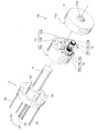
- FIG. 2 is an exploded perspective view showing the open / close direction restricting mechanism 10.
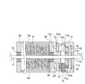
- FIG. 3 is a partially omitted sectional view taken along line AA of FIG.
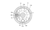
- FIG. 4 is a left side view showing the flange 11 of FIG.
- FIG. 5 is a right side view showing the bracket 12, the two-way clutch 13 and the rotation damper 14 of FIG. 6 is a cross-sectional view taken along the line BB in FIG.
- the shutter device 1 vertically opens and closes an opening of a large area such as a garage or a store.
- the shutter device 1 includes a slat 2 capable of moving up and down, a winding member 3 for winding the slat 2, and a fixed shaft 4 disposed at the rotational center of the winding member 3.
- a housing space 5 for housing the slat 2, the winding member 3 and the fixed shaft 4 is covered with a housing cover 5 a and protected without being exposed to wind and rain.
- the slat member 2 is configured such that slat members 2a disposed adjacent to each other vertically are hinged via a peristaltic shaft 2b.
- the upper end of the slat 2 is coupled to the winding member 3 and is configured to be wound around the outer periphery of the winding member 3. Both ends of the slat 2 are accommodated in sliding grooves (not shown) of the guide rails 6 erected on the left and right, so that fluttering caused by the elevation of the slat 2 is suppressed.
- the winding member 3 is formed in a substantially cylindrical shape. Specifically, the winding member 3 is joined to one end of four shafts 3a horizontally extended, bearings 3b and 3c press-fit fitted to the fixed shaft 4, and one end of the shaft 3a It comprises a wheel 3d which is externally fitted to 3b, and a wheel 3e which is joined to the other end of the shaft 3a and which is externally fitted to a bearing 3c.
- the winding member 3 is rotationally driven in the winding direction (opening direction) D1
- the slat 2 is taken up by the winding member 3 and ascends
- the winding member 3 is in the reverse winding direction (closing direction )
- the number of shafts 3a is not limited to four, and may be two to three or five or more.
- the fixed shaft 4 is bridged between the shutter brackets 7 respectively provided on the upper portions of the left and right guide rails 6, and both ends of the fixed shaft 4 are fixedly supported by the shutter bracket 7, respectively.
- a torsion spring (torsion coil spring) 8 is wound around the fixed shaft 4.
- the torsion spring 8 is accommodated in the winding member 3. One end of the torsion spring 8 is fixed to the wheel 3 d, and the other end is fixed to the fixed shaft 4. The torsion spring 8 biases the wheel 3d in the winding direction D1. Thereby, the slat 2 can be lifted with a slight force.
- the opening / closing direction restricting mechanism 10 includes a flange 11 fixed to an end of the fixed shaft 4, a bracket 12 disposed adjacent to the flange 11, and a two-way clutch 13 provided on the side surface of the bracket 12. ing.
- An internal gear 11 b is formed on the facing surface 11 a of the flange 11 facing the bracket 12.
- the flange 11 is formed in a disk shape, and the tip of the bolt B screwed into the bolt hole 11 c bites into the fixed shaft 4 so that the flange 11 is fixed to the fixed shaft 4.
- Reference numeral 11 d denotes an insertion hole through which the fixed shaft 4 is inserted.
- the bracket 12 is formed in a cylindrical shape, and a small diameter portion 3d 'of the wheel 3d is inserted through the central hole 12a.
- a two-way clutch 13 is provided on one side 12 b opposite to the flange 11 of the bracket 12.
- the other side 12 c of the bracket 12 is joined to the wheel 3 d. Accordingly, the bracket 12 is configured to rotate integrally with the winding member 3 via the wheel 3d.
- a clutch planet external gear 13 b is provided on the input shaft 13 a of the two-way clutch 13.
- the clutch planet external gear 13 b can be engaged with the internal gear 11 b of the flange 11.
- the bracket 12 is driven to rotate relative to the flange 11, the internal gear 11b of the flange 11 and the clutch planetary external gear 13b of the two-way clutch 13 mesh, and the input shaft 13a of the two-way clutch 13 rotates. .
- the two-way clutch 13 has a known configuration, and either rotation (forward rotation) along the winding direction D1 of the winding member 3 or rotation (reverse rotation) along the reverse winding direction D2 of the winding member 3 It allows one and limits the other.
- the rotation direction (locking direction) restricted by the two-way clutch 13 can be arbitrarily switched by applying an external force equal to or greater than a predetermined threshold value in the direction in which the rotation is already restricted.
- a friction switching type or an electrical switching type is known as a driving method of the two-way clutch 13, and either of the present invention may be adopted. The former can be introduced at low cost.
- the opening / closing direction control mechanism 10 further includes a rotation damper 14.
- the rotation damper 14 is provided on one side surface 12 b of the bracket 12.
- a damper planetary outer gear 14 b capable of meshing with the internal gear 11 b of the flange 11 is provided on the input shaft 14 a of the rotary damper 14.
- the rotation damper 14 has a known configuration, and brakes the rotational movement of the input shaft 14a input through the damper planetary outer gear 14b.
- the rotation damper 14 is, for example, an oil damper or the like that brakes the rotation of the input shaft 14 a with viscous resistance of oil.
- the rotation damper 14 is preferably an infinite rotation damper which decelerates the winding member 3 at least when the winding member 3 rotates in the winding direction D1.
- a bidirectional infinite rotation damper is adopted as the rotation damper 14
- the raising and lowering of the slat 2 is braked and the slat 2 is raised and lowered gently.
- a one-way infinite rotation damper is adopted as the rotation damper 14
- the rise of the slat 2 is braked, and the slat 2 is gently raised while the force for braking the descent of the slat 2 when lowering the slat 2 ( Since no damper force is applied, it can be operated with a light force.
- the two-way clutch 13 and the rotary damper 14 are disposed concentrically around the fixed shaft 4 as viewed from the axial direction of the fixed shaft 4.
- the number of installed rotary dampers 14 provided in the opening / closing direction regulating mechanism 10 is not limited to one, and may be two or more. When two rotational dampers 14 are provided, it is preferable that the rotational dampers 14 be disposed so as to sandwich the two-way clutch 13.
- the side surface 13 c of the two-way clutch 13 and the side surface 14 c of the rotary damper 14 are substantially flush with each other when viewed from the radial direction of the fixed shaft 4.
- 12 can rotate at a substantially constant position with respect to the flange 11.
- the opening / closing direction restricting mechanism 10 is not limited to the above-described configuration, and for example, the flange 11 can be integrally provided integrally with the winding member 3 and the bracket 12 is fixed to the fixed shaft 4 It does not matter. Further, an external gear (not shown) may be engraved on the outer periphery of the bracket 12 instead of the internal gear 11b, and this external gear may be engaged with the clutch planetary external gear 13b and the damper planetary external gear 14b. Absent.
- 7 (a) to 7 (d) are partially cutaway front views showing the operation of the opening / closing direction control mechanism 10.
- FIG. In the following, the case where the friction switching type two-way clutch 13 is used will be described as an example.
- the external force F2 for lowering the slat 2 is removed at a position where the slat 2 is to be stopped. This is because, as shown in FIG. 7C, a torque in the winding direction D1 is exerted by the biasing force F1 of the torsion spring 8 and the two-way clutch 13 limits the forward rotation of the winding member 3.
- the slat 2 is to stop at the position where the biasing force F1 is removed.
- the rotation damper 14 suppresses excessive acceleration of the damper planetary outer gear and the winding member 3 by the biasing force applied to the winding member 3 by the torsion spring 8.
- the elevating operation of the slat 2 is buffered, and the slat 2 can be raised gently.
- the bidirectional infinite rotation damper for braking the forward rotation and the reverse rotation of the winding member 3 is installed, the elevation of the slat 2 is buffered, and the slat 2 can be moved up and down quietly.
- the clutch planetary outer gear 13b is fixed by applying an external force to the take-up member 3 in the direction in which the two-way clutch 13 permits rotation.
- the slat 2 can be raised and lowered.
- the clutch planetary outer gear 13b is prevented from revolving around the fixed shaft 4, Since the rotation of the member 3 and the bracket 12 about the fixed axis 4 is blocked, the elevation of the slat 2 is blocked.
- the slat 2 is moving up or down. In any case, the slat 2 can be stopped.
- FIG. 8 is a schematic view showing a manual type sliding door apparatus 20 to which the open / close direction restricting mechanism 30 is applied.
- FIG. 9 is an enlarged view of an essential part showing the open / close direction restricting mechanism 30. As shown in FIG.
- the sliding door apparatus 20 is configured to slide in the horizontal direction the entrance of a dwelling, a sick room, or the like to open and close.
- the lifting and lowering door device 20 includes a lifting rail 21 provided substantially horizontally and a lifting and pulling door 22 suspended from the lifting rail 21.
- the hanging rail 21 is provided at the top of the entrance and extends horizontally.
- the lifting rail 21 is inclined so as to be slightly lowered in the closing direction D3 in which the lifting door 22 closes.
- the hanging rail 21 is formed with a rack 21 a and a traveling surface 21 b.
- a liner 22a capable of traveling on the traveling surface 21b of the lifting rail 21 is provided.
- the opening and closing direction restricting mechanism 30 is disposed at the top of the lifting and lowering door 22.
- the opening and closing direction restricting mechanism 30 includes a base member 31 disposed at the upper end of the hanging and pulling door 22 and a two-way clutch 32 disposed on the side surface of the base member 31.
- the base member 31 is formed in a rectangular shape, and is joined to the upper end of the hanging and sliding door 22 so as to slide integrally with the hanging and sliding door 22.
- the two-way clutch 32 is provided on an opposing surface 31 a facing the suspension rail 21 of the base member 31.
- the input shaft 32 a of the two-way clutch 32 is provided with a clutch pinion 32 b capable of meshing with the rack 21 a of the suspension rail 21.
- the two-way clutch 32 has a known configuration, and either a slide (closing operation) along a closing direction D3 in which the lifting door 22 closes or a slide (opening operation) along an opening direction D4 in which the lifting door 22 opens Allow and limit the other.
- the direction (locking direction) of the slide restricted by the two-way clutch 32 can be arbitrarily switched by applying an external force equal to or greater than a predetermined threshold value in the direction in which the slide is already restricted.
- a friction switching type or an electrical switching type is known as a driving method of the two-way clutch 32, and either of the present invention may be adopted. The former can be introduced at low cost.
- the opening / closing direction restriction mechanism 30 further includes a rotation damper 33 disposed on the facing surface 31 a of the base member 31 so as to be adjacent to the two-way clutch 32.
- the damper pinion 33 b provided on the input shaft 33 a of the rotation damper 33 can mesh with the rack 21 a of the suspension rail 21.
- the rotation damper 33 is, for example, an oil damper or the like that brakes the rotation of the input shaft 33a with viscous resistance of oil.
- the rotation damper 33 is preferably an infinite rotation damper which decelerates at least a slide of the lifting door 22 in the closing direction D3.
- a bidirectional infinite rotation damper is adopted as the rotation damper 33, the opening and closing of the lifting and lowering door 22 is braked, and the lifting and lowering door 22 is gently opened and closed.
- the one-way infinite rotation damper is adopted as the rotation damper 33, the closing operation of the hanging and pulling door 22 is braked, and the hanging and pulling door 22 closes gently.
- 10 (a) to 10 (d) are schematic views showing the operation of the opening / closing direction regulating mechanism 30.
- FIG. In the following, the case where the friction switching type two-way clutch 32 is used will be described as an example.
- the two-way clutch 32 In the state where the hanging and pulling door 22 is closed, as shown in FIG. 10A, the two-way clutch 32 is in the open operation blocking state in which the sliding along the opening direction D4 of the hanging and pulling door 22 is restricted.
- a self-weight F4 in the closing direction D3 acts on the front and rear sides, the clutch pinion 32b is limited to bite in the rack 21a, and the slide of the lifting and lowering door 22 in the opening direction D4 is limited.
- the lifting and pulling door 22 is reopened only by applying the external force F in the opening direction D4 to the lifting and pulling door 22 Can.
- the rotation damper 33 suppresses that the lifting and lowering door 22 accelerates excessively.
- a one-way infinite rotation damper is installed to brake the sliding of the lifting door 22 in the closing direction D3
- the closing operation of the lifting door 22 is buffered and the lifting door 22 can be closed quietly.
- the bidirectional infinite rotation damper which brakes the slide to the closing direction D3 and the opening direction D4 of the hanging and pulling door 22 is installed, opening and closing of the hanging and pulling door 22 is buffered, and the hanging and pulling door 22 may be opened and closed quietly. it can.
- the external force is applied to the suspension door 22 in the direction in which the two-way clutch 32 allows rotation of the clutch pinion 32b. Since the clutch pinion 32b is engaged with the rack 21a of the suspension rail 21 to advance, the suspension door 22 can be opened and closed. On the other hand, when external force is applied to the hanging and pulling door 22 in the direction in which the two-way clutch 32 blocks the rotation of the clutch pinion 32b, relative sliding of the hanging and sliding door 22 with respect to the hanging rail 21 is blocked. , Sliding of the lifting door 22 is impeded.
- the lifting door 22 is open or closed. In any case, the hanging and pulling door 22 can be stopped.
- the present invention may be applied to anything that positions the actuating member moving relative to the fixing member at a desired position.
Abstract
[Problem] To provide an opening/closing direction restriction mechanism for a manual shutter device and an opening/closing direction restriction mechanism for a suspended sliding door device which are capable of achieving, at low costs, a mechanism for positioning, at a desired position, an operation member that moves relative to a fixed member. [Solution] This opening/closing direction restriction mechanism 10 is provided with: a flange 11 fixedly mounted on a fixed shaft 4; a bracket 12 which is loosely fitted to the fixed shaft 4 and can be integrally rotated with a winding member 3; and a two-way clutch 13 which can be switched between a reverse rotation inhibited state in which the revolution of a planetary external gear 13b along a winding direction D1 of the winding member 3 is allowed and the revolution of the planetary external gear 13b along an unwinding direction D2 is inhibited, and a forward rotation inhibited state in which the revolution of the planetary external gear 13b along the winding direction D1 of the winding member 3 is inhibited and the revolution of the planetary external gear 13b along the unwinding direction D2 is allowed.
Description
本発明は、回転駆動された巻取部材がスラットを昇降させる手動式シャッター装置に用いられる巻取部材の回転方向を規制する開閉方向規制機構、及び、吊レールに吊引戸を吊設した吊引戸装置に用いられる吊引戸のスライド方向を規制する開閉方向規制機構に関する。
The present invention relates to an open / close direction restricting mechanism for restricting the rotational direction of a winding member used in a manual shutter device in which a rotationally driven winding member raises and lowers a slat, and a hanging sliding door in which a hanging sliding door is suspended from a hanging rail The present invention relates to an open / close direction restricting mechanism that restricts the sliding direction of a hanging sliding door used in the device.
従来より、建物の出入口を開閉するシャッター装置や部屋の開口部を開閉する吊引戸装置が知られている。電動シャッターに関する特許文献1には、電動モータが巻上シャフトを回転駆動させることにより、スラットが巻取シャフトに巻き取られるものが開示されている。巻取シャフトの回転は、操作スイッチを介して入力される電動モータの回転方向及びON/OFFによって制御され、スラットは任意の位置で停止するようになっている。
2. Description of the Related Art Conventionally, a shutter device that opens and closes a doorway of a building and a hanging door device that opens and closes an opening of a room are known. Patent Document 1 relating to an electric shutter discloses that a slat is wound around a winding shaft by an electric motor rotationally driving a winding shaft. The rotation of the winding shaft is controlled by the rotation direction and ON / OFF of the electric motor input via the operation switch, and the slat is stopped at an arbitrary position.
また、手動シャッターに関する特許文献2には、固定軸に巻回されたトーションスプリングが、巻上シャフトに対してスラットが巻き取られる巻取方向のトルクを付与するものが開示されている。これにより、ユーザがスラットを僅かに持ち上げると、トーションスプリングのトルクによって、スラットは全て巻き上げられるようになっている。
Further, Patent Document 2 relating to a manual shutter discloses that a torsion spring wound around a fixed shaft applies a torque in a winding direction in which a slat is wound on a winding shaft. As a result, when the user slightly lifts the slat, the torque of the torsion spring causes all the slats to be rolled up.
また、吊引戸装置に関する特許文献3には、電動モータの出力軸に直結されたピニオンがドアの上部側面に設けられたラックと噛み合っており、電動モータが駆動し、ピニオンが正回転するとドアが開方向に移動し、ピニオンが逆回転するとドアが閉方向に移動する引戸式ドアの自動開閉装置が開示されている。
Further, in Patent Document 3 relating to the sliding door apparatus, a pinion directly connected to the output shaft of the electric motor meshes with a rack provided on the upper side surface of the door, and when the electric motor is driven and the pinion rotates forward, the door There is disclosed an automatic opening / closing device of a sliding door which moves in the opening direction and the door moves in the closing direction when the pinion reversely rotates.
しかしながら、特許文献1記載の電動シャッターでは、電動モータのモータシャフトを巻取シャフトと連結させたり、電動モータの操作スイッチを設ける必要があり、電動シャッターの構造が複雑になり、電動シャッターの設置コストが高くなりがちであるという問題があった。
However, in the electric shutter described in Patent Document 1, it is necessary to connect the motor shaft of the electric motor with the take-up shaft, or to provide an operation switch of the electric motor, the structure of the electric shutter becomes complicated, and the installation cost of the electric shutter Problem that tends to be high.
また、特許文献2記載の手動シャッターでは、スラットが全て巻き上げられた全開状態か、又はスラットが全て降りた全閉状態の何れかの位置しか選択することができないため、スラットを任意の位置で停止させることができず、不必要にスラットを昇降させなければならないという問題があった。
In addition, with the manual shutter described in Patent Document 2, the slat can be stopped at any position, since it is possible to select either the fully open state in which all the slats are wound up or the fully closed state in which all the slats are lowered. There is a problem that the slat has to be raised and lowered unnecessarily.
また、特許文献3記載の引戸式ドアの自動開閉装置では、ドアを電動モータで開閉させるため、開閉装置の構造が複雑になり引戸の設置コストが高くなりがちであるという問題があった。
Further, in the automatic door opening and closing device for a sliding door described in Patent Document 3, there is a problem that the structure of the opening and closing device becomes complicated and the installation cost of the sliding door tends to be high because the door is opened and closed by an electric motor.
そこで、固定軸や吊りレール等の固定部材に対して相対的に移動する巻取部材や吊引戸等の作動部材を所望の位置に位置決めする機構を低コストで提供するために解決すべき技術的課題が生じてくるのであり、本発明は、この課題を解決することを目的とする。
Therefore, it is technically necessary to provide a mechanism for positioning at a desired position a moving member such as a winding member or a hanging door that moves relative to a fixed member such as a fixed shaft or a hanging rail at low cost. The problem arises, and the present invention aims to solve this problem.
本発明は、上記目的を達成するために提案するものであり、請求項1記載の発明は、略水平に延設された固定軸と、該固定軸に回転可能に設けられてスラットを巻き取る巻取部材と、該巻取部材に内装されて前記スラットを巻き取る巻取方向に前記巻取部材を付勢するトーションスプリングと、から成る手動式シャッター装置の開閉方向規制機構において、前記巻取部材又は前記固定軸の一方に取り付けられたブラケットと、該ブラケットに隣接配置されると共に前記巻取部材又は前記固定軸の他方に取り付けられたフランジと、前記ブラケットの前記フランジに対向する対向面に配置された2ウェイクラッチと、を備え、前記フランジに形成された歯車と前記2ウェイクラッチの入力軸に装着されたクラッチ用外歯車とが噛合可能に配置され、前記2ウェイクラッチは、前記巻取部材の巻取方向に沿った前記クラッチ用外歯車の自転を許容して反巻取方向に沿った前記クラッチ用外歯車の自転を阻止する逆転阻止状態と、前記巻取部材の巻取方向に沿った前記クラッチ用外歯車の自転を阻止して反巻取方向に沿った前記クラッチ用外歯車の自転を許容する正転阻止状態とを切換可能に設けられている手動式シャッター装置の開閉方向規制機構を提供する。
The present invention is proposed to achieve the above object, and the invention according to the first aspect comprises a fixed shaft extending substantially horizontally and a rotary shaft rotatably provided on the fixed shaft to take up a slat. The winding direction control mechanism of a manual shutter device, comprising: a winding member; and a torsion spring which is incorporated in the winding member and biases the winding member in a winding direction for winding the slat. A bracket attached to one of the member or the fixed shaft, a flange disposed adjacent to the bracket and attached to the other of the take-up member or the fixed shaft, and a surface opposite to the flange of the bracket And a two-way clutch disposed, wherein the gear formed on the flange and the clutch external gear mounted on the input shaft of the two-way clutch can be engaged with each other The two-way clutch allows rotation of the clutch external gear along the winding direction of the winding member and prevents rotation of the clutch external gear along the reverse winding direction. And a forward rotation blocking state in which rotation of the clutch external gear along the winding direction of the winding member is blocked and rotation of the clutch external gear along the reverse winding direction is permitted. Provided is an open / close direction regulating mechanism for a manual shutter device.
この構成によれば、2ウェイクラッチが回転を許容する方向に向かって巻取部材に外力が付与されることにより、クラッチ用外歯車が入力軸まわりに自転し、巻取部材及び該巻取部材に取り付けられたブラケット又はフランジが固定軸まわりに回転するため、スラットを昇降させることができる。一方、2ウェイクラッチが回転を阻止する方向に向かって巻取部材に外力が付与された場合には、クラッチ用外歯車が入力軸まわりに自転することが妨げられ、巻取部材及び該巻取部材に取り付けられたブラケット又はフランジの固定軸まわりの回転が阻止されるため、スラットの昇降が妨げられる。また、2ウェイクラッチが許容するクラッチ用外歯車の自転方向、即ち2ウェイクラッチの逆転阻止状態及び正転阻止状態は任意に切換自在なため、スラットの上昇途中又は下降途中の何れであっても、スラットを停止させることができる。
According to this configuration, the external gear for the clutch is rotated about the input shaft by applying an external force to the take-up member in the direction in which the two-way clutch permits rotation, and the take-up member and the take-up member The slats can be raised and lowered as the brackets or flanges mounted on the slats rotate about a fixed axis. On the other hand, when an external force is applied to the winding member in the direction in which the two-way clutch blocks the rotation, the clutch external gear is prevented from rotating around the input shaft, and the winding member and the winding Since the rotation of the bracket or flange attached to the member is prevented around the fixed axis, the slat is prevented from moving up and down. In addition, since the rotation direction of the clutch external gear permitted by the 2-way clutch, that is, the reverse rotation prevention state and the forward rotation prevention state of the 2-way clutch can be arbitrarily switched, the slat may be either rising or falling , You can stop the slat.
請求項2記載の発明は、請求項1記載の発明の構成に加えて、前記ブラケットは、筒状に形成され、前記固定軸に外嵌されるとともに前記巻取部材と一体に回転可能に設けられ、前記フランジは、前記固定軸に固着されている手動式シャッター装置の開閉方向規制機構を提供する。
According to a second aspect of the present invention, in addition to the configuration of the first aspect, the bracket is formed in a tubular shape, externally fitted to the fixed shaft, and rotatably provided integrally with the winding member. The flange provides an open / close direction control mechanism of the manual shutter device fixed to the fixed shaft.
この構成によれば、2ウェイクラッチが回転を許容する方向に向かって巻取部材に外力が付与されると、ブラケット及び巻取部材が固定軸まわりに回転するため、スラットを昇降させることができる。一方、2ウェイクラッチが回転を阻止する方向に向かって巻取部材に外力が付与されると、ブラケット及び巻取部材の固定軸まわりの回転が阻止されるため、スラットの昇降が妨げられる。
According to this configuration, when an external force is applied to the take-up member in a direction in which the two-way clutch permits rotation, the bracket and the take-up member rotate around the fixed shaft, so the slat can be raised and lowered. . On the other hand, when an external force is applied to the take-up member in the direction in which the two-way clutch blocks the rotation, the rotation of the bracket and the take-up member about the fixed axis is blocked, thereby elevating the slat.
請求項3記載の発明は、請求項1又は2記載の発明の構成に加えて、前記歯車は、前記フランジの前記ブラケットに対向する対向面に形成された内歯車である手動式シャッター装置の開閉方向規制機構を提供する。
According to the invention of claim 3, in addition to the constitution of the invention of claim 1 or 2, opening and closing of the manual shutter device is an internal gear formed on an opposing surface of the flange facing the bracket. Provide a direction control mechanism.
この構成によれば、2ウェイクラッチが回転を許容する方向に向かって巻取部材に外力が付与されると、クラッチ用外歯車が内歯車と噛み合って固定軸まわりに公転し、巻取部材が固定軸まわりに回転するため、スラットを昇降させることができる。一方、2ウェイクラッチが回転を阻止する方向に向かって巻取部材に外力が付与されると、クラッチ用外歯車が固定軸まわりに公転することが妨げられ、巻取部材の固定軸まわりの回転が阻止されるため、スラットの昇降が妨げられる。
According to this configuration, when an external force is applied to the take-up member in the direction in which the two-way clutch allows rotation, the clutch external gear meshes with the internal gear and revolves around the fixed shaft, and the take-up member The slat can be raised and lowered to rotate around a fixed axis. On the other hand, when an external force is applied to the winding member in the direction in which the two-way clutch blocks the rotation, the clutch external gear is prevented from revolving around the fixed shaft, and rotation of the winding member around the fixed shaft Of the slat is prevented because the
請求項4記載の発明は、請求項1乃至3の何れか1項記載の発明の構成に加えて、前記ブラケットの対向面に設けられ、前記歯車と噛合可能なダンパ用外歯車を有する回転ダンパを備えている手動式シャッター装置の開閉方向規制機構を提供する。
According to a fourth aspect of the invention, in addition to the structure of the invention according to any one of the first to third aspects, a rotation damper provided on an opposing surface of the bracket and having a damper external gear meshable with the gear. An open / close direction regulating mechanism of a manual shutter device is provided.
この構成によれば、回転ダンパは、フランジ及びダンパ用外歯車を介して回転ダンパに入力される巻取部材の回転を制動するため、スラットを静かに昇降させることができる。
According to this configuration, the rotation damper can quietly raise and lower the slat in order to brake the rotation of the winding member input to the rotation damper via the flange and the damper external gear.
請求項5記載の発明は、請求項4記載の発明の構成に加えて、前記回転ダンパは、前記巻取部材が巻取方向に回転する際に前記巻取部材を減速させる無限角回転ダンパである手動式シャッター装置の開閉方向規制機構を提供する。
According to a fifth aspect of the present invention, in addition to the configuration of the fourth aspect, the rotation damper is an infinite-angle rotation damper that decelerates the winding member when the winding member rotates in the winding direction. Provided is an open / close direction regulation mechanism of a manual shutter device.
この構成によれば、回転ダンパが、スラットが上昇する際に巻取部材の回転を制動することにより、巻取部材が巻取方向に過度に加速して回転することを抑制するため、スラットを静かに且つ安全に上昇させることができる。
According to this configuration, the rotation damper suppresses the rotation of the winding member by braking the rotation of the winding member when the slat rises, thereby preventing the winding member from excessively accelerating and rotating in the winding direction. It can be raised quietly and safely.
請求項6記載の発明は、請求項4又は5記載の発明の構成に加えて、前記2ウェイクラッチと前記回転ダンパとは、前記固定軸まわりに同心円上に配置されている手動式シャッター装置の開閉方向規制機構を提供する。
According to a sixth aspect of the present invention, in addition to the configuration of the fourth aspect, the two-way clutch and the rotary damper are disposed concentrically around the fixed axis. Provide an open / close direction control mechanism.
この構成によれば、2ウェイクラッチのクラッチ用外歯車と回転ダンパのダンパ用外歯車とが、フランジの歯車を介して連動するため、開閉方向規制機構を省スペースで設置することができる。
According to this configuration, the clutch external gear of the two-way clutch and the damper external gear of the rotational damper interlock with each other through the gear of the flange, so that the opening / closing direction restriction mechanism can be installed in a space-saving manner.
請求項7記載の発明は、略水平に設けられた吊りレールに吊引戸を吊設し、該吊引戸に前記吊りレール上を走行可能なライナーを設けて成る吊引戸装置の開閉方向規制機構において、前記吊引戸の上端にベース部材を固着し、前記ベース部材の前記吊りレールと対向する対向面に2ウェイクラッチを配置し、前記吊りレールに形成されたラックと前記2ウェイクラッチの入力軸に装着されたクラッチ用ピニオンとが噛合可能に配置され、前記2ウェイクラッチは、前記吊引戸の閉方向へのスライドに応じた前記クラッチ用ピニオンの自転を許容して前記吊引戸の開方向へのスライドに応じた前記クラッチ用ピニオンの自転を阻止する開阻止状態と、前記吊引戸の閉方向へのスライドに応じた前記クラッチ用ピニオンの自転を阻止して前記吊引戸の開方向へのスライドに応じた前記クラッチ用ピニオンの自転を許容する閉阻止状態とを切換可能に設けられている吊引戸装置の開閉方向規制機構を提供する。
The invention according to claim 7 is the opening / closing direction restricting mechanism of the hanging sliding door apparatus having the hanging sliding door suspended from the hanging rail provided substantially horizontally and providing the hanging sliding door with a liner capable of traveling on the hanging rail. A base member is fixed to the upper end of the hanging door, and a two-way clutch is disposed on an opposite surface of the base member facing the hanging rail, and a rack formed on the hanging rail and an input shaft of the two-way clutch The two-way clutch allows rotation of the clutch pinion in accordance with the sliding of the hanging door in the closing direction, and the two-way clutch allows rotation of the hanging door in the opening direction. The suspension is performed by blocking the rotation of the clutch pinion in response to the opening of the clutch pinion in response to the slide and the sliding of the suspension door in the closing direction. Providing an opening and closing direction regulating mechanism of the sliding door device suspended provided a closed blocking state to allow sliding rotation of the pinion clutch in accordance with to the door open direction switchable.
この構成によれば、2ウェイクラッチが回転を許容する方向に向かって吊引戸に外力が付与されることにより、2ウェイクラッチのクラッチ用ピニオンが吊りレールのラックと噛み合って進むため、吊引戸を開閉させることができる。一方、2ウェイクラッチが回転を阻止する方向に向かって吊引戸に外力が付与される場合には、クラッチ用ピニオンの自転が阻止されて吊りレールに対する吊引戸の相対的なスライドが阻止されるため、吊引戸のスライドが妨げられる。また、2ウェイクラッチが許容するクラッチ用ピニオンの回転方向、即ち2ウェイクラッチの開阻止状態及び閉阻止状態は任意に切換自在なため、吊引戸の開動作中又は閉動作中の何れであっても、吊引戸を停止させることができる。
According to this configuration, an external force is applied to the hanging and sliding door in the direction in which the two-way clutch permits rotation, whereby the clutch pinion for the two-way clutch engages with the rack of the hanging rail and proceeds. It can be opened and closed. On the other hand, when external force is applied to the hanging and sliding door in the direction in which the two-way clutch blocks rotation, rotation of the clutch pinion is blocked and relative sliding of the hanging and sliding door with respect to the suspension rail is blocked. , Sliding sliding door is hindered. In addition, since the rotation direction of the clutch pinion permitted by the 2-way clutch, that is, the open blocking state and the closed blocking state of the 2-way clutch can be arbitrarily switched, either during the opening operation or closing operation of the hanging door Also, the sliding door can be stopped.
請求項8記載の発明は、請求項7記載の発明の構成に加えて、前記ラックと噛合可能なダンパ用ピニオンを有し、前記ベース部材の対向面に設けられた回転ダンパを備えている吊引戸装置の開閉方向規制機構を提供する。
According to an eighth aspect of the present invention, in addition to the configuration of the seventh aspect, a suspension including a damper pinion capable of meshing with the rack, and a rotation damper provided on the opposite surface of the base member Provided is a mechanism for restricting the opening and closing direction of a sliding door device.
この構成によれば、回転ダンパは、吊りレール及びダンパ用ピニオンを介して回転ダンパに入力されるベース部材及び吊引戸のスライドを制動するため、吊引戸を静かに開閉させることができる。
According to this configuration, since the rotation damper brakes the slide of the base member and the hanging and sliding door input to the rotating damper via the suspension rail and the damper pinion, the hanging and sliding door can be opened and closed quietly.
請求項9記載の発明は、請求項8記載の発明の構成に加えて、前記回転ダンパは、前記吊引戸が閉方向にスライドする際に前記吊引戸を減速させる無限角回転ダンパである吊引戸装置の開閉方向規制機構を提供する。
In the invention according to claim 9, in addition to the configuration according to the invention according to claim 8, the swing sliding door is an infinite-angle rotary damper which decelerates the swing sliding door when the swing sliding door slides in a closing direction. To provide a mechanism for restricting the opening and closing direction of the device.
この構成によれば、回転ダンパは、吊引戸の閉動作中に吊引戸のスライドを制動することにより、吊引戸が閉方向に過度に加速することを抑制するため、吊引戸を静かに且つ安全に閉じることができる。
According to this configuration, the rotation damper suppresses the excessive acceleration of the hanging door in the closing direction by braking the sliding door during the closing movement of the hanging door, thereby making the hanging door quiet and safe. Can be closed.
本発明に係る手動式シャッターの開閉方向規制機構によれば、2ウェイクラッチが回転を許容する方向に向かって巻取部材に外力が付与されることにより、クラッチ用外歯車が入力軸まわりに自転し、巻取部材及び該巻取部材に取り付けられたブラケット又はフランジが固定軸まわりに回転するため、スラットを昇降させることができる。一方、2ウェイクラッチが回転を阻止する方向に向かって巻取部材に外力が付与された場合には、クラッチ用外歯車が入力軸まわりに自転することが妨げられ、巻取部材及び該巻取部材に取り付けられたブラケット又はフランジの固定軸まわりの回転が阻止されるため、スラットの昇降が妨げられる。また、2ウェイクラッチが許容するクラッチ用外歯車の自転方向、即ち2ウェイクラッチの逆転阻止状態及び正転阻止状態は任意に切換自在なため、スラットの上昇途中又は下降途中の何れであっても、スラットを停止させることができる。
According to the opening and closing direction restricting mechanism of the manual shutter according to the present invention, the external gear for the clutch is rotated about the input shaft by applying an external force to the take-up member in the direction in which the two-way clutch permits rotation. Since the winding member and the bracket or flange attached to the winding member rotate around a fixed axis, the slat can be raised and lowered. On the other hand, when an external force is applied to the winding member in the direction in which the two-way clutch blocks the rotation, the clutch external gear is prevented from rotating around the input shaft, and the winding member and the winding Since the rotation of the bracket or flange attached to the member is prevented around the fixed axis, the slat is prevented from moving up and down. In addition, since the rotation direction of the clutch external gear permitted by the 2-way clutch, that is, the reverse rotation prevention state and the forward rotation prevention state of the 2-way clutch can be arbitrarily switched, the slat may be either rising or falling , You can stop the slat.
本発明に係る吊引戸の開閉方向規制機構によれば、2ウェイクラッチが回転を許容する方向に向かって吊引戸に外力が付与されることにより、2ウェイクラッチのクラッチ用ピニオンが吊りレールのラックと噛み合って進むため、吊引戸を開閉させることができる。一方、2ウェイクラッチが回転を阻止する方向に向かって吊引戸に外力が付与される場合には、クラッチ用ピニオンの自転が阻止されて吊りレールに対する吊引戸の相対的なスライドが阻止されるため、吊引戸のスライドが妨げられる。また、許容するクラッチ用ピニオンの回転方向、即ち2ウェイクラッチの開阻止状態及び閉阻止状態は任意に切換自在なため、吊引戸の開動作中又は閉動作中の何れであっても、吊引戸を停止させることができる。
According to the opening and closing direction regulating mechanism of the hanging and sliding door according to the present invention, the clutch pinion of the two way clutch is the rack of the hanging rail by applying an external force to the hanging and sliding door in the direction in which the two way clutch permits rotation. The sliding door can be opened and closed in order to engage with it. On the other hand, when external force is applied to the hanging and sliding door in the direction in which the two-way clutch blocks rotation, rotation of the clutch pinion is blocked and relative sliding of the hanging and sliding door with respect to the suspension rail is blocked. , Sliding sliding door is hindered. In addition, since the allowable rotation direction of the clutch pinion, that is, the open blocking state and the closed blocking state of the two-way clutch can be arbitrarily switched, the hanging and pulling door can be switched either during opening or closing Can be stopped.
本発明に係る手動式シャッター装置の開閉方向規制機構は、固定軸に対して相対的に回転する巻取部材を所望の位置に位置決めする機構を低コストで提供するために、略水平に延設された固定軸と、該固定軸に回転可能に設けられてスラットを巻き取る巻取部材と、該巻取部材に内装されて前記スラットを巻き取る巻取方向に前記巻取部材を付勢するトーションスプリングと、から成る手動式シャッター装置の開閉方向規制機構において、巻取部材又は固定軸の一方に取り付けられたブラケットと、ブラケットに隣接配置されると共に巻取部材又は固定軸の他方に取り付けられたフランジと、ブラケットのフランジに対向する対向面に配置された2ウェイクラッチと、を備え、フランジに形成された歯車と2ウェイクラッチの入力軸に装着されたクラッチ用外歯車とが噛合可能に配置され、2ウェイクラッチは、巻取部材の巻取方向に沿ったクラッチ用外歯車の自転を許容して反巻取方向に沿ったクラッチ用外歯車の自転を阻止する逆転阻止状態と、巻取部材の巻取方向に沿ったクラッチ用外歯車の自転を阻止して反巻取方向に沿ったクラッチ用外歯車の自転を許容する正転阻止状態とを切換可能に設けられていることにより実現した。
The opening / closing direction restricting mechanism of the manual shutter device according to the present invention extends approximately horizontally to provide a mechanism for positioning the winding member rotating relative to the fixed shaft at a desired position at low cost. The fixed shaft, the winding member rotatably provided on the fixed shaft to wind the slat, and the winding member installed in the winding member to bias the winding member in the winding direction to wind the slat An opening / closing direction control mechanism of a manual shutter device comprising a torsion spring, a bracket attached to one of a winding member or a fixed shaft, and a bracket disposed adjacent to the bracket and attached to the other of the winding member or the fixed shaft And a two-way clutch disposed on the opposite surface facing the flange of the bracket, and mounted on the gear formed on the flange and the input shaft of the two-way clutch The two-way clutch allows rotation of the clutch external gear along the winding direction of the take-up member, and allows the clutch external gear to rotate in the reverse winding direction. Reverse rotation preventing the rotation of the clutch, and rotation preventing the rotation of the clutch external gear along the reverse winding direction by blocking the rotation of the clutch external gear along the winding direction of the winding member And can be switched.
本発明に係る吊引戸の開閉方向規制機構は、吊りレールに対して相対的にスライドする吊引戸を所望の位置に位置決めする機構を低コストで提供するために、略水平に設けられた吊りレールに吊引戸を吊設し、吊引戸に吊りレール上を走行可能なライナーを設けて成る吊引戸装置の開閉方向規制機構において、吊引戸の上端にベース部材を固着し、ベース部材の吊りレールと対向する対向面に2ウェイクラッチを配置し、吊りレールに形成されたラックと2ウェイクラッチの入力軸に装着されたクラッチ用ピニオンとが噛合可能に配置され、2ウェイクラッチは、吊引戸の閉方向へのスライドに応じたクラッチ用ピニオンの自転を許容して吊引戸の開方向へのスライドに応じたクラッチ用ピニオンの自転を阻止する開阻止状態と、吊引戸の閉方向へのスライドに応じたクラッチ用ピニオンの自転を阻止して吊引戸の開方向へのスライドに応じたクラッチ用ピニオンの自転を許容する閉阻止状態とを切換可能に設けられていることにより実現した。
The opening and closing direction regulating mechanism of the hanging and sliding door according to the present invention is a hanging rail provided substantially horizontally to provide a mechanism for positioning the hanging and sliding door relative to the hanging rail at a desired position at low cost. The base member is fixed to the upper end of the hanging door in the opening / closing direction regulating mechanism of the hanging door device configured to hang the hanging door on the hanging door and provide the liner capable of traveling on the hanging rail on the hanging door. A two-way clutch is disposed on the opposite surface facing each other, and the rack formed on the suspension rail and the pinion for the clutch mounted on the input shaft of the two-way clutch can be engaged so that the two-way clutch An open blocking state for permitting rotation of the clutch pinion in response to sliding in the direction and blocking rotation of the clutch pinion in response to sliding in the opening direction of the hanging door; It is possible to prevent switching of the clutch pinion from rotating in response to sliding in the direction, and switch to a closed blocking state that allows rotation of the clutch pinion in response to sliding of the hanging door in the opening direction. did.
以下、本発明の一実施例に係るシャッター装置1について、図面に基づいて説明する。なお、以下の実施例において、構成要素の数、数値、量、範囲等に言及する場合、特に明示した場合及び原理的に明らかに特定の数に限定される場合を除き、その特定の数に限定されるものではなく、特定の数以上でも以下でも構わない。
Hereinafter, a shutter device 1 according to an embodiment of the present invention will be described based on the drawings. In the following examples, when referring to the number, numerical value, amount, range, etc. of constituent elements, unless specifically indicated otherwise and in principle when clearly limited to a specific number, The number is not limited and may be more or less than a specific number.
また、構成要素等の形状、位置関係に言及するときは、特に明示した場合及び原理的に明らかにそうでないと考えられる場合等を除き、実質的にその形状等に近似又は類似するもの等を含む。
In addition, when referring to the shapes of components, etc., and positional relationships, those that are substantially similar or similar to the shapes etc., unless specifically stated otherwise or where it is considered to be otherwise clearly apparent in principle Including.
また、図面は、特徴を分かり易くするために特徴的な部分を拡大する等して誇張する場合があり、構成要素の寸法比率等が実際と同じであるとは限らない。
In the drawings, characteristic parts may be enlarged or enlarged to make features easy to understand, and dimensional ratios of constituent elements are not necessarily the same as in actuality.
図1は、開閉方向規制機構10を適用した手動式のシャッター装置1を示す一部切欠正面図である。図2は、開閉方向規制機構10を示す分解斜視図である。図3は、図1のA-A線一部省略断面図である。図4は、図2のフランジ11を示す左側面図である。図5は、図2のブラケット12、2ウェイクラッチ13及び回転ダンパ14を示す右側面図である。図6は、図1のB-B線断面図である。
FIG. 1 is a partially cutaway front view showing a manual shutter device 1 to which the open / close direction restricting mechanism 10 is applied. FIG. 2 is an exploded perspective view showing the open / close direction restricting mechanism 10. FIG. 3 is a partially omitted sectional view taken along line AA of FIG. FIG. 4 is a left side view showing the flange 11 of FIG. FIG. 5 is a right side view showing the bracket 12, the two-way clutch 13 and the rotation damper 14 of FIG. 6 is a cross-sectional view taken along the line BB in FIG.
シャッター装置1は、車庫や店舗等の大面積の開口部を上下に昇降して開閉するものである。シャッター装置1は、上下に昇降可能なスラット2と、スラット2を巻き取る巻取部材3と、巻取部材3の回転中心に配置された固定軸4と、を備えている。スラット2、巻取部材3及び固定軸4を収容する収容スペース5は、収容カバー5aで覆われており、風雨に曝されることなく保護されている。
The shutter device 1 vertically opens and closes an opening of a large area such as a garage or a store. The shutter device 1 includes a slat 2 capable of moving up and down, a winding member 3 for winding the slat 2, and a fixed shaft 4 disposed at the rotational center of the winding member 3. A housing space 5 for housing the slat 2, the winding member 3 and the fixed shaft 4 is covered with a housing cover 5 a and protected without being exposed to wind and rain.
スラット2は、上下に隣接して配置されたスラット部材2aが搖動軸2bを介してヒンジ結合されて構成されている。スラット2の上端は、巻取部材3に結合されており、巻取部材3の外周に巻き取られる構成になっている。スラット2の両端は、左右に立設されたガイドレール6の図示しない摺動溝内に収容されており、スラット2の昇降に伴うバタつきが抑制されるようになっている。
The slat member 2 is configured such that slat members 2a disposed adjacent to each other vertically are hinged via a peristaltic shaft 2b. The upper end of the slat 2 is coupled to the winding member 3 and is configured to be wound around the outer periphery of the winding member 3. Both ends of the slat 2 are accommodated in sliding grooves (not shown) of the guide rails 6 erected on the left and right, so that fluttering caused by the elevation of the slat 2 is suppressed.
巻取部材3は、略円筒状に形成されている。具体的には、巻取部材3は、水平方向に延伸された4本のシャフト3aと、固定軸4に圧入嵌合されたベアリング3b、3cと、シャフト3aの一方端に接合されるとともにベアリング3bに外装されたホイール3dと、シャフト3aの他方端に接合されるとともにベアリング3cに外装されたホイール3eと、で構成されている。これにより、巻取部材3が巻取方向(開方向)D1に回転駆動されると、スラット2が巻取部材3に巻き取られて上昇し、巻取部材3が反巻取方向(閉方向)D2に回転駆動されると、スラット2が送り出されて下降するようになっている。なお、シャフト3aの本数は、4本に限定されるものではなく、2~3本でも、5本以上であっても構わない。
The winding member 3 is formed in a substantially cylindrical shape. Specifically, the winding member 3 is joined to one end of four shafts 3a horizontally extended, bearings 3b and 3c press-fit fitted to the fixed shaft 4, and one end of the shaft 3a It comprises a wheel 3d which is externally fitted to 3b, and a wheel 3e which is joined to the other end of the shaft 3a and which is externally fitted to a bearing 3c. Thereby, when the winding member 3 is rotationally driven in the winding direction (opening direction) D1, the slat 2 is taken up by the winding member 3 and ascends, and the winding member 3 is in the reverse winding direction (closing direction ) When driven to rotate by D2, the slat 2 is fed out and descends. The number of shafts 3a is not limited to four, and may be two to three or five or more.
固定軸4は、左右のガイドレール6の上部にそれぞれ設けられたシャッターブラケット7間に架設されており、固定軸4の両端は、それぞれシャッターブラケット7に固定支持されている。固定軸4には、トーションスプリング(ねじりコイルバネ)8が巻回されている。
The fixed shaft 4 is bridged between the shutter brackets 7 respectively provided on the upper portions of the left and right guide rails 6, and both ends of the fixed shaft 4 are fixedly supported by the shutter bracket 7, respectively. A torsion spring (torsion coil spring) 8 is wound around the fixed shaft 4.
トーションスプリング8は、巻取部材3内に収容されている。トーションスプリング8の一方端は、ホイール3dに固定されており、他方端は、固定軸4に固定されている。トーションスプリング8は、ホイール3d対して巻取方向D1に付勢するようになっている。これにより、僅かな力でスラット2を上昇させることができる。
The torsion spring 8 is accommodated in the winding member 3. One end of the torsion spring 8 is fixed to the wheel 3 d, and the other end is fixed to the fixed shaft 4. The torsion spring 8 biases the wheel 3d in the winding direction D1. Thereby, the slat 2 can be lifted with a slight force.
次に、開閉方向規制機構10の構造について、図面に基づいて説明する。開閉方向規制機構10は、固定軸4の端部に固着されたフランジ11と、フランジ11に隣接して配置されたブラケット12と、ブラケット12の側面に設けられた2ウェイクラッチ13と、を備えている。
Next, the structure of the open / close direction restricting mechanism 10 will be described based on the drawings. The opening / closing direction restricting mechanism 10 includes a flange 11 fixed to an end of the fixed shaft 4, a bracket 12 disposed adjacent to the flange 11, and a two-way clutch 13 provided on the side surface of the bracket 12. ing.
フランジ11のブラケット12と対向する対向面11aには、内歯車11bが形成されている。フランジ11は、円板状に形成されており、ボルト孔11cに螺挿されたボルトBの先端が固定軸4に食い込むことにより、フランジ11が固定軸4に固着される。なお、符号11dは、固定軸4を挿通する挿通孔である。
An internal gear 11 b is formed on the facing surface 11 a of the flange 11 facing the bracket 12. The flange 11 is formed in a disk shape, and the tip of the bolt B screwed into the bolt hole 11 c bites into the fixed shaft 4 so that the flange 11 is fixed to the fixed shaft 4. Reference numeral 11 d denotes an insertion hole through which the fixed shaft 4 is inserted.
ブラケット12は、円筒状に形成されており、中央の孔部12aにホイール3dの小径部3d’が挿通されている。ブラケット12のフランジ11と対向する一方側面12bには、2ウェイクラッチ13が設けられている。ブラケット12の他方側面12cには、ホイール3dと接合されている。したがって、ブラケット12は、ホイール3dを介して巻取部材3と一体で回転するようになっている。
The bracket 12 is formed in a cylindrical shape, and a small diameter portion 3d 'of the wheel 3d is inserted through the central hole 12a. A two-way clutch 13 is provided on one side 12 b opposite to the flange 11 of the bracket 12. The other side 12 c of the bracket 12 is joined to the wheel 3 d. Accordingly, the bracket 12 is configured to rotate integrally with the winding member 3 via the wheel 3d.
2ウェイクラッチ13の入力軸13aには、クラッチ用遊星外歯車13bが設けられている。クラッチ用遊星外歯車13bは、フランジ11の内歯車11bと噛合可能になっている。ブラケット12がフランジ11に対して相対的に回転駆動されると、フランジ11の内歯車11bと2ウェイクラッチ13のクラッチ用遊星外歯車13bとが噛み合い、2ウェイクラッチ13の入力軸13aが回転する。
A clutch planet external gear 13 b is provided on the input shaft 13 a of the two-way clutch 13. The clutch planet external gear 13 b can be engaged with the internal gear 11 b of the flange 11. When the bracket 12 is driven to rotate relative to the flange 11, the internal gear 11b of the flange 11 and the clutch planetary external gear 13b of the two-way clutch 13 mesh, and the input shaft 13a of the two-way clutch 13 rotates. .
2ウェイクラッチ13は、公知の構成であり、巻取部材3の巻取方向D1に沿った回転(正転)と巻取部材3の反巻取方向D2に沿った回転(逆転)の何れか一方を許容し、他方を制限するものである。2ウェイクラッチ13が制限する回転方向(ロック方向)は、既に回転が制限されている方向に所定閾値以上の外力が付与されることにより、任意に切換可能である。2ウェイクラッチ13の駆動方式として、摩擦切換式又は電気切換式が知られており、本発明でも何れを採用しても構わない。前者であれば、低コストで導入することができる。
The two-way clutch 13 has a known configuration, and either rotation (forward rotation) along the winding direction D1 of the winding member 3 or rotation (reverse rotation) along the reverse winding direction D2 of the winding member 3 It allows one and limits the other. The rotation direction (locking direction) restricted by the two-way clutch 13 can be arbitrarily switched by applying an external force equal to or greater than a predetermined threshold value in the direction in which the rotation is already restricted. A friction switching type or an electrical switching type is known as a driving method of the two-way clutch 13, and either of the present invention may be adopted. The former can be introduced at low cost.
開閉方向規制機構10は、回転ダンパ14を更に備えている。回転ダンパ14は、ブラケット12の一方側面12bに設けられている。回転ダンパ14の入力軸14aには、フランジ11の内歯車11bと噛合可能なダンパ用遊星外歯車14bが設けられている。回転ダンパ14は、公知の構成から成り、ダンパ用遊星外歯車14bを介して入力された入力軸14aの回転運動を制動する。回転ダンパ14は、例えば、入力軸14aの回転をオイルの粘性抵抗で制動するオイルダンパ等である。回転ダンパ14は、少なくとも、巻取部材3が巻取方向D1に回転する際に巻取部材3を減速させる無限回転ダンパが好ましい。回転ダンパ14に双方向無限回転ダンパを採用すれば、スラット2の昇降が制動されて、スラット2が緩やかに昇降される。また、回転ダンパ14に一方向無限回転ダンパを採用すれば、スラット2の上昇が制動されて、スラット2が緩やかに上昇されると共に、スラット2を下す際にスラット2の下降を制動する力(ダンパ力)が付与されないため軽い力で操作することができる。
The opening / closing direction control mechanism 10 further includes a rotation damper 14. The rotation damper 14 is provided on one side surface 12 b of the bracket 12. A damper planetary outer gear 14 b capable of meshing with the internal gear 11 b of the flange 11 is provided on the input shaft 14 a of the rotary damper 14. The rotation damper 14 has a known configuration, and brakes the rotational movement of the input shaft 14a input through the damper planetary outer gear 14b. The rotation damper 14 is, for example, an oil damper or the like that brakes the rotation of the input shaft 14 a with viscous resistance of oil. The rotation damper 14 is preferably an infinite rotation damper which decelerates the winding member 3 at least when the winding member 3 rotates in the winding direction D1. If a bidirectional infinite rotation damper is adopted as the rotation damper 14, the raising and lowering of the slat 2 is braked and the slat 2 is raised and lowered gently. In addition, if a one-way infinite rotation damper is adopted as the rotation damper 14, the rise of the slat 2 is braked, and the slat 2 is gently raised while the force for braking the descent of the slat 2 when lowering the slat 2 ( Since no damper force is applied, it can be operated with a light force.
2ウェイクラッチ13及び回転ダンパ14は、固定軸4の軸方向から視て、固定軸4まわりに同心円上に配置されている。なお、開閉方向規制機構10に設けられる回転ダンパ14の設置個数は、1つに限定されるものではなく、2つ以上であっても構わない。回転ダンパ14を2つ設ける場合には、2ウェイクラッチ13を挟むように、回転ダンパ14が配置されるのが好ましい。
The two-way clutch 13 and the rotary damper 14 are disposed concentrically around the fixed shaft 4 as viewed from the axial direction of the fixed shaft 4. The number of installed rotary dampers 14 provided in the opening / closing direction regulating mechanism 10 is not limited to one, and may be two or more. When two rotational dampers 14 are provided, it is preferable that the rotational dampers 14 be disposed so as to sandwich the two-way clutch 13.
2ウェイクラッチ13の側面13c及び回転ダンパ14の側面14cは、固定軸4の径方向から視て略面一に形成されている。これにより、クラッチ用遊星外歯車13b及び内歯車11bの噛み合い位置並びにダンパ用遊星外歯車14bと内歯車11bとの噛み合い位置が固定軸4の軸方向に位置ズレすることが抑制されるため、ブラケット12がフランジ11に対して略一定の位置で回転運動することができる。
The side surface 13 c of the two-way clutch 13 and the side surface 14 c of the rotary damper 14 are substantially flush with each other when viewed from the radial direction of the fixed shaft 4. As a result, displacement of the meshing position of the clutch planetary outer gear 13b and the inner gear 11b and the meshing position of the damper planetary outer gear 14b and the inner gear 11b in the axial direction of the fixed shaft 4 is suppressed. 12 can rotate at a substantially constant position with respect to the flange 11.
なお、開閉方向規制機構10は、上述した構成に限定されるものではなく、例えば、フランジ11が巻取部材3と一体に可能に設けられ、ブラケット12が固定軸4に固着されたものであっても構わない。また、内歯車11bの代わりにブラケット12の外周に図示しない外歯車を刻設し、この外歯車とクラッチ用遊星外歯車13b及びダンパ用遊星外歯車14bとを噛合可能な構成であっても構わない。
In addition, the opening / closing direction restricting mechanism 10 is not limited to the above-described configuration, and for example, the flange 11 can be integrally provided integrally with the winding member 3 and the bracket 12 is fixed to the fixed shaft 4 It does not matter. Further, an external gear (not shown) may be engraved on the outer periphery of the bracket 12 instead of the internal gear 11b, and this external gear may be engaged with the clutch planetary external gear 13b and the damper planetary external gear 14b. Absent.
次に、開閉方向規制機構10の作用について説明する。図7(a)~(d)は、開閉方向規制機構10の作用を示す一部切欠正面図である。なお、以下では、摩擦切換式の2ウェイクラッチ13を用いた場合を例に説明する。
Next, the operation of the opening and closing direction control mechanism 10 will be described. 7 (a) to 7 (d) are partially cutaway front views showing the operation of the opening / closing direction control mechanism 10. FIG. In the following, the case where the friction switching type two-way clutch 13 is used will be described as an example.
スラット2が巻取部材3に巻き取られた状態では、図7(a)に示すように、2ウェイクラッチ13が巻取部材3の反巻取方向D2に沿った回転を制限する逆転阻止状態であり、且つ、トーションスプリング8の付勢力F1によって、巻取部材3には、巻取方向D1へのトルクが常に付与されているため、クラッチ用遊星外歯車13bが内歯車11bを噛み進むことが制限され、巻取部材3の反巻取方向D2への回転駆動は制限されている。
In the state where the slat 2 is wound around the winding member 3, as shown in FIG. 7A, the reverse blocking state in which the two-way clutch 13 restricts the rotation of the winding member 3 along the reverse winding direction D2. Since the torque in the take-up direction D1 is always applied to the take-up member 3 by the urging force F1 of the torsion spring 8, the clutch planetary outer gear 13b bites the internal gear 11b. Is limited, and the rotational drive of the winding member 3 in the reverse winding direction D2 is limited.
図7(b)に示すように、スラット2が巻取部材3に巻き取られた状態から、所定閾値以上の反巻取方向D2の外力F2が巻取部材3に付与されると、2ウェイクラッチ13の逆転阻止状態が解除され、巻取部材3の巻取方向D1に沿った回転を制限する正転阻止状態に移行し、巻取部材3の反巻取方向D2への回転駆動が可能となる。これにより、2ウェイクラッチ13のクラッチ用遊星外歯車13b及び回転ダンパ14のダンパ用遊星外歯車14bが自転しながら、2ウェイクラッチ13及び回転ダンパ14が固定軸4まわりに反巻取方向D2に沿って公転することにより、スラット2を降下させることができる。
As shown in FIG. 7B, when an external force F2 in the reverse winding direction D2 equal to or more than a predetermined threshold value is applied to the winding member 3 from the state in which the slat 2 is wound around the winding member 3, two-way The reverse rotation prevention state of the clutch 13 is released, and the state shifts to a normal rotation prevention state in which the rotation of the winding member 3 along the winding direction D1 is limited, and rotational driving of the winding member 3 in the reverse winding direction D2 is possible. It becomes. Thus, while the clutch planetary outer gear 13b of the two-way clutch 13 and the damper planetary outer gear 14b of the rotary damper 14 rotate, the two-way clutch 13 and the rotary damper 14 rotate around the fixed shaft 4 in the reverse winding direction D2. By revolving along, the slat 2 can be lowered.
次に、スラット2を任意の位置で停止させる場合には、スラット2を停止させたい位置で、スラット2を降下させる外力F2を取り除く。これは、図7(c)に示すように、トーションスプリング8の付勢力F1による巻取方向D1へのトルクが作用すると共に、2ウェイクラッチ13が巻取部材3の正転を制限するため、スラット2は付勢力F1が取り除かれた位置で停止するためである。
Next, when the slat 2 is stopped at an arbitrary position, the external force F2 for lowering the slat 2 is removed at a position where the slat 2 is to be stopped. This is because, as shown in FIG. 7C, a torque in the winding direction D1 is exerted by the biasing force F1 of the torsion spring 8 and the two-way clutch 13 limits the forward rotation of the winding member 3. The slat 2 is to stop at the position where the biasing force F1 is removed.
スラット2を一時停止状態から再び降下させる場合には、2ウェイクラッチ13は正転阻止状態であるから、反巻取方向D2の外力を付与するだけでスラット2を再び降下させることができる。
When the slat 2 is lowered again from the temporary stop state, since the two-way clutch 13 is in the forward rotation blocking state, the slat 2 can be lowered again only by applying an external force in the reverse winding direction D2.
スラット2を一時停止状態から上昇させる場合には、図7(d)に示すように、巻取部材3の巻取方向D1に所定閾値以上の外力F3が付与されると、2ウェイクラッチ13の正転阻止状態が解除されて、逆転阻止状態に移行する。そして、2ウェイクラッチ13の正転阻止状態解除後は、トーションスプリング8の付勢力F1により、2ウェイクラッチ13のクラッチ用遊星外歯車13b及び回転ダンパ14のダンパ用遊星外歯車14bが自転しながら、2ウェイクラッチ13及び回転ダンパ14が固定軸4まわりに巻取方向D1に沿って公転し、巻取部材3は巻取方向D1に回転駆動されることにより、スラット2を自動で上昇させることができる。
When raising the slat 2 from the temporary stop state, as shown in FIG. 7D, when an external force F3 equal to or greater than a predetermined threshold value is applied in the winding direction D1 of the winding member 3, The forward rotation prevention state is released and the reverse rotation prevention state is entered. Then, after releasing the normal rotation prevention state of the two-way clutch 13, while the clutch planetary outer gear 13b of the two-way clutch 13 and the damper planetary outer gear 14b of the rotation damper 14 rotate by the biasing force F1 of the torsion spring 8. The two-way clutch 13 and the rotary damper 14 revolve around the fixed shaft 4 along the take-up direction D1, and the take-up member 3 is rotationally driven in the take-up direction D1, thereby automatically raising the slat 2 Can.
また、回転ダンパ14は、トーションスプリング8が巻取部材3に付与する付勢力によってダンパ用遊星外歯車、巻取部材3が過剰に加速することを抑制する。例えば、巻取部材3の正転を制動する一方向無限回転ダンパを設置した場合には、スラット2の上昇動作が緩衝され、スラット2を静かに上昇させることができる。また、巻取部材3の正転及び逆転を制動する双方向無限回転ダンパを設置した場合には、スラット2の昇降が緩衝され、スラット2を静かに昇降させることができる。
Further, the rotation damper 14 suppresses excessive acceleration of the damper planetary outer gear and the winding member 3 by the biasing force applied to the winding member 3 by the torsion spring 8. For example, when a one-way infinite rotation damper for braking the forward rotation of the winding member 3 is installed, the elevating operation of the slat 2 is buffered, and the slat 2 can be raised gently. In addition, when the bidirectional infinite rotation damper for braking the forward rotation and the reverse rotation of the winding member 3 is installed, the elevation of the slat 2 is buffered, and the slat 2 can be moved up and down quietly.
このようにして、本発明に係る開閉方向規制機構10は、2ウェイクラッチ13が回転を許容する方向に向かって巻取部材3に外力が付与されることにより、クラッチ用遊星外歯車13bが固定軸4まわりに公転し、巻取部材3及びブラケット12が固定軸4まわりに回転するため、スラット2を昇降させることができる。一方、2ウェイクラッチ13が回転を阻止する方向に向かって巻取部材3に外力が付与される場合には、クラッチ用遊星外歯車13bが固定軸4まわりに公転することが妨げられ、巻取部材3及びブラケット12の固定軸4まわりの回転が阻止されるため、スラット2の昇降が阻止される。また、2ウェイクラッチ13が許容するクラッチ用遊星外歯車13bの回転方向、即ち2ウェイクラッチ13の逆転阻止状態及び正転阻止状態は任意に切換自在なため、スラット2の上昇途中又は下降途中の何れであっても、スラット2を停止させることができる。
Thus, in the opening / closing direction restricting mechanism 10 according to the present invention, the clutch planetary outer gear 13b is fixed by applying an external force to the take-up member 3 in the direction in which the two-way clutch 13 permits rotation. As the winding member 3 and the bracket 12 rotate around the fixed shaft 4 by revolving around the shaft 4, the slat 2 can be raised and lowered. On the other hand, when an external force is applied to the take-up member 3 in the direction in which the two-way clutch 13 blocks the rotation, the clutch planetary outer gear 13b is prevented from revolving around the fixed shaft 4, Since the rotation of the member 3 and the bracket 12 about the fixed axis 4 is blocked, the elevation of the slat 2 is blocked. In addition, since the rotation direction of the clutch planetary outer gear 13b permitted by the two-way clutch 13, that is, the reverse rotation prevention state and the forward rotation prevention state of the two-way clutch 13 can be arbitrarily switched, the slat 2 is moving up or down. In any case, the slat 2 can be stopped.
次に、本発明の一実施例に係る吊引戸装置20について、図面に基づいて説明する。図8は、開閉方向規制機構30を適用した手動式の吊引戸装置20を示す模式図である。図9は、開閉方向規制機構30を示す要部拡大図である。
Next, a hanging sliding door device 20 according to an embodiment of the present invention will be described based on the drawings. FIG. 8 is a schematic view showing a manual type sliding door apparatus 20 to which the open / close direction restricting mechanism 30 is applied. FIG. 9 is an enlarged view of an essential part showing the open / close direction restricting mechanism 30. As shown in FIG.
吊引戸装置20は、住居や病室等の出入口を水平方向にスライドして開閉するものである。吊引戸装置20は、略水平に設けられた吊りレール21と、吊りレール21に吊設された吊引戸22と、を備えている。
The sliding door apparatus 20 is configured to slide in the horizontal direction the entrance of a dwelling, a sick room, or the like to open and close. The lifting and lowering door device 20 includes a lifting rail 21 provided substantially horizontally and a lifting and pulling door 22 suspended from the lifting rail 21.
吊りレール21は、出入口の上部に設けられ、水平方向に延伸されている。吊りレール21は、吊引戸22が閉じる閉方向D3に向かって僅かに下がるように傾斜している。吊りレール21には、ラック21a及び走行面21bが形成されている。
The hanging rail 21 is provided at the top of the entrance and extends horizontally. The lifting rail 21 is inclined so as to be slightly lowered in the closing direction D3 in which the lifting door 22 closes. The hanging rail 21 is formed with a rack 21 a and a traveling surface 21 b.
吊引戸22の上部左右端には、吊りレール21の走行面21b上を走行可能なライナー22aが設けられている。
At the upper left and right ends of the lifting and lowering door 22, a liner 22a capable of traveling on the traveling surface 21b of the lifting rail 21 is provided.
開閉方向規制機構30は、吊引戸22の上部に配置されている。開閉方向規制機構30は、吊引戸22の上端に配置されたベース部材31と、ベース部材31の側面に配置された2ウェイクラッチ32と、を備えている。
The opening and closing direction restricting mechanism 30 is disposed at the top of the lifting and lowering door 22. The opening and closing direction restricting mechanism 30 includes a base member 31 disposed at the upper end of the hanging and pulling door 22 and a two-way clutch 32 disposed on the side surface of the base member 31.
ベース部材31は、矩形状に形成されおり、吊引戸22の上端に接合され、吊引戸22と一体となってスライドするようになっている。
The base member 31 is formed in a rectangular shape, and is joined to the upper end of the hanging and sliding door 22 so as to slide integrally with the hanging and sliding door 22.
2ウェイクラッチ32は、ベース部材31の吊りレール21と対向する対向面31aに設けられている。2ウェイクラッチ32の入力軸32aには、吊りレール21のラック21aと噛合可能なクラッチ用ピニオン32bが設けられている。吊引戸22及びベース部材31が吊りレール21に対して相対的にスライドすると、吊りレール21のラック21aと2ウェイクラッチ32のクラッチ用ピニオン32bとが噛み合い、2ウェイクラッチ32の入力軸32aが回転する。
The two-way clutch 32 is provided on an opposing surface 31 a facing the suspension rail 21 of the base member 31. The input shaft 32 a of the two-way clutch 32 is provided with a clutch pinion 32 b capable of meshing with the rack 21 a of the suspension rail 21. When the lifting and pulling door 22 and the base member 31 slide relative to the lifting rail 21, the rack 21 a of the lifting rail 21 and the clutch pinion 32 b of the two-way clutch 32 engage with each other, and the input shaft 32 a of the two-way clutch 32 rotates. Do.
2ウェイクラッチ32は、公知の構成であり、吊引戸22が閉じる閉方向D3に沿ったスライド(閉動作)と吊引戸22が開く開方向D4に沿ったスライド(開動作)の何れか一方を許容し、他方を制限するものである。2ウェイクラッチ32が制限するスライドの向き(ロック方向)は、既にスライドが制限されている方向に所定閾値以上の外力が付与されることにより、任意に切換可能である。2ウェイクラッチ32の駆動方式として、摩擦切換式又は電気切換式が知られており、本発明でも何れを採用しても構わない。前者であれば、低コストで導入することができる。
The two-way clutch 32 has a known configuration, and either a slide (closing operation) along a closing direction D3 in which the lifting door 22 closes or a slide (opening operation) along an opening direction D4 in which the lifting door 22 opens Allow and limit the other. The direction (locking direction) of the slide restricted by the two-way clutch 32 can be arbitrarily switched by applying an external force equal to or greater than a predetermined threshold value in the direction in which the slide is already restricted. A friction switching type or an electrical switching type is known as a driving method of the two-way clutch 32, and either of the present invention may be adopted. The former can be introduced at low cost.
また、開閉方向規制機構30は、2ウェイクラッチ32と隣り合うようにベース部材31の対向面31aに配置された回転ダンパ33を更に備えている。回転ダンパ33の入力軸33aに設けられたダンパ用ピニオン33bは、吊りレール21のラック21aと噛合可能になっている。回転ダンパ33は、例えば、入力軸33aの回転をオイルの粘性抵抗で制動するオイルダンパ等である。回転ダンパ33は、少なくとも、吊引戸22の閉方向D3へのスライドを減速させる無限回転ダンパが好ましい。回転ダンパ33に双方向無限回転ダンパを採用すれば、吊引戸22の開閉が制動されて、吊引戸22が緩やかに開閉される。また、回転ダンパ33に一方向無限回転ダンパを採用すれば、吊引戸22の閉動作が制動されて、吊引戸22が緩やかに閉じる。
In addition, the opening / closing direction restriction mechanism 30 further includes a rotation damper 33 disposed on the facing surface 31 a of the base member 31 so as to be adjacent to the two-way clutch 32. The damper pinion 33 b provided on the input shaft 33 a of the rotation damper 33 can mesh with the rack 21 a of the suspension rail 21. The rotation damper 33 is, for example, an oil damper or the like that brakes the rotation of the input shaft 33a with viscous resistance of oil. The rotation damper 33 is preferably an infinite rotation damper which decelerates at least a slide of the lifting door 22 in the closing direction D3. If a bidirectional infinite rotation damper is adopted as the rotation damper 33, the opening and closing of the lifting and lowering door 22 is braked, and the lifting and lowering door 22 is gently opened and closed. In addition, if the one-way infinite rotation damper is adopted as the rotation damper 33, the closing operation of the hanging and pulling door 22 is braked, and the hanging and pulling door 22 closes gently.
次に、開閉方向規制機構30の作用について説明する。図10(a)~(d)は、開閉方向規制機構30の作用を示す模式図である。なお、以下では、摩擦切換式の2ウェイクラッチ32を用いた場合を例に説明する。
Next, the operation of the opening / closing direction regulating mechanism 30 will be described. 10 (a) to 10 (d) are schematic views showing the operation of the opening / closing direction regulating mechanism 30. FIG. In the following, the case where the friction switching type two-way clutch 32 is used will be described as an example.
吊引戸22が閉じた状態では、図10(a)に示すように、2ウェイクラッチ32が吊引戸22の開方向D4に沿ったスライドを制限する開動作阻止状態であり、且つ、吊引戸22には閉方向D3への自重F4が作用しており、クラッチ用ピニオン32bがラック21aを噛み進むことが制限され、吊引戸22の開方向D4へのスライドが制限されている。
In the state where the hanging and pulling door 22 is closed, as shown in FIG. 10A, the two-way clutch 32 is in the open operation blocking state in which the sliding along the opening direction D4 of the hanging and pulling door 22 is restricted. A self-weight F4 in the closing direction D3 acts on the front and rear sides, the clutch pinion 32b is limited to bite in the rack 21a, and the slide of the lifting and lowering door 22 in the opening direction D4 is limited.
図10(b)に示すように、吊引戸22が閉じた状態から、所定閾値以上の開方向D4の外力F5が吊引戸22に付与されると、2ウェイクラッチ32の開動作阻止状態が解除され、吊引戸22の閉方向D3に沿ったスライドを制限する閉動作阻止状態に移行し、吊引戸22の開方向D4へのスライドが可能となる。これにより、吊引戸22を開くことができる。
As shown in FIG. 10 (b), when an external force F5 in the opening direction D4 equal to or more than a predetermined threshold value is applied to the hanging and pulling door 22 from the state where the pulling and pulling door 22 is closed Thus, the sliding / sliding door 22 can be slid in the opening direction D4. Thereby, the hanging and pulling door 22 can be opened.
次に、吊引戸22を任意の位置で停止させる場合には、吊引戸22を停止させたい位置で、吊引戸22に作用する外力F5を取り除く。これは、図10(c)に示すように、吊引戸22には自重F4が作用すると共に、2ウェイクラッチ32は吊引戸22の閉動作を制限するため、吊引戸22は外力が取り除かれた位置で停止するためである。
Next, when the lifting and lowering door 22 is stopped at an arbitrary position, the external force F5 acting on the lifting and lowering door 22 is removed at a position where it is desired to stop the lifting and lowering door 22. This is because, as shown in FIG. 10 (c), the self-weight F4 acts on the lifting and lowering door 22 and the two-way clutch 32 restricts the closing operation of the lifting and lowering door 22, so the lifting and lowering door 22 is removed from the external force. It is to stop at the position.
吊引戸22を一時停止状態から再び開く場合には、2ウェイクラッチ32は閉動作阻止状態であるから、吊引戸22に開方向D4の外力Fが付与されるだけで吊引戸22を再び開くことができる。
Since the two-way clutch 32 is in the closing prevention state when the lifting and pulling door 22 is reopened from the temporary stop state, the lifting and pulling door 22 is reopened only by applying the external force F in the opening direction D4 to the lifting and pulling door 22 Can.
吊引戸22を一時停止状態から閉じる場合には、図10(d)に示すように、所定閾値以上の閉方向D3の外力F6が吊引戸22に付与されると、2ウェイクラッチ32の閉動作阻止状態が解除されて、開動作阻止状態に移行する。そして、2ウェイクラッチ32の閉動作阻止状態解除後は、吊引戸22の自重F4により、吊引戸22を自動的に閉方向D3にスライドさせることができる。
When closing the hanging and pulling door 22 from the temporary stop state, as shown in FIG. 10D, when the pulling and pulling door 22 is applied with an external force F6 in the closing direction D3 equal to or more than a predetermined threshold, the closing operation of the two-way clutch 32 The blocking state is released, and the open operation blocking state is entered. Then, after releasing the closed state blocking state of the two-way clutch 32, the lifting and pulling door 22 can be automatically slid in the closing direction D3 by the weight F4 of the lifting and lowering door 22.
また、回転ダンパ33は、吊引戸22が過剰に加速することを抑制する。例えば、吊引戸22の閉方向D3へのスライドを制動する一方向無限回転ダンパを設置した場合には、吊引戸22の閉動作が緩衝され、吊引戸22を静かに閉じることができる。また、吊引戸22の閉方向D3及び開方向D4へのスライドを制動する双方向無限回転ダンパを設置した場合には、吊引戸22の開閉が緩衝され、吊引戸22を静かに開閉させることができる。
Moreover, the rotation damper 33 suppresses that the lifting and lowering door 22 accelerates excessively. For example, when a one-way infinite rotation damper is installed to brake the sliding of the lifting door 22 in the closing direction D3, the closing operation of the lifting door 22 is buffered and the lifting door 22 can be closed quietly. Moreover, when the bidirectional infinite rotation damper which brakes the slide to the closing direction D3 and the opening direction D4 of the hanging and pulling door 22 is installed, opening and closing of the hanging and pulling door 22 is buffered, and the hanging and pulling door 22 may be opened and closed quietly. it can.
このようにして、本発明に係る開閉方向規制機構30は、2ウェイクラッチ32がクラッチ用ピニオン32bの自転を許容する方向に向かって吊引戸22に外力が付与されることにより、2ウェイクラッチ32のクラッチ用ピニオン32bが吊りレール21のラック21aと噛み合って進むため、吊引戸22を開閉させることができる。一方、2ウェイクラッチ32がクラッチ用ピニオン32bの自転を阻止する方向に向かって吊引戸22に外力が付与される場合には、吊りレール21に対する吊引戸22の相対的なスライドが阻止されるため、吊引戸22のスライドが妨げられる。また、2ウェイクラッチ32が許容するクラッチ用ピニオン32bの回転方向、即ち2ウェイクラッチ32の開阻止状態及び閉阻止状態は任意に切換自在なため、吊引戸22の開動作中又は閉動作中の何れであっても、吊引戸22を停止させることができる。
Thus, in the opening / closing direction restricting mechanism 30 according to the present invention, the external force is applied to the suspension door 22 in the direction in which the two-way clutch 32 allows rotation of the clutch pinion 32b. Since the clutch pinion 32b is engaged with the rack 21a of the suspension rail 21 to advance, the suspension door 22 can be opened and closed. On the other hand, when external force is applied to the hanging and pulling door 22 in the direction in which the two-way clutch 32 blocks the rotation of the clutch pinion 32b, relative sliding of the hanging and sliding door 22 with respect to the hanging rail 21 is blocked. , Sliding of the lifting door 22 is impeded. Further, since the rotation direction of the clutch pinion 32b permitted by the two-way clutch 32, that is, the open blocking state and the closed blocking state of the two-way clutch 32 can be arbitrarily switched, the lifting door 22 is open or closed. In any case, the hanging and pulling door 22 can be stopped.
なお、本発明は、本発明の精神を逸脱しない限り種々の改変をなすことができ、そして、本発明が該改変されたものにも及ぶことは当然である。
The present invention can be modified in various ways without departing from the spirit of the present invention, and it goes without saying that the present invention extends to those modified as well.
本発明は、固定部材に対して相対的に移動する作動部材を所望の位置に位置決めするものであれば如何なるものに適用しても構わない。
The present invention may be applied to anything that positions the actuating member moving relative to the fixing member at a desired position.
1 ・・・ シャッター装置
2 ・・・ スラット
2a・・・ スラット部材
2b・・・ 搖動軸
3 ・・・ 巻取部材(作動部材)
3a・・・ シャフト
3b、3c・・・軸受
3d、3e・・・ホイール
4 ・・・ 固定軸(固定部材)
5 ・・・ 収容スペース
6 ・・・ ガイドレール
7 ・・・ シャッターブラケット
8 ・・・ トーションスプリング
10 ・・・ (シャッター装置の)開閉方向規制機構
11 ・・・ フランジ
11a・・・ (フランジの)対向面
11b・・・ 内歯車
11c・・・ ボルト孔
11d・・・ 挿通孔
12 ・・・ ブラケット
12a・・・ 孔部
12b・・・ 一方側面
12c・・・ 他方側面
13 ・・・ 2ウェイクラッチ
13a・・・ 入力軸
13b・・・ クラッチ用遊星外歯車
13c・・・ (2ウェイクラッチの)側面
14 ・・・ 回転ダンパ
14a・・・ 入力軸
14b・・・ ダンパ用遊星外歯車
14c・・・ (回転ダンパの)側面
20 ・・・ 吊引戸装置
21 ・・・ 吊りレール(固定部材)
21a・・・ ラック
22 ・・・ 吊引戸(作動部材)
30 ・・・ (吊引戸装置の)開閉方向規制機構
31 ・・・ ベース部材
31a・・・ (ベース部材の)対向面
32 ・・・ 2ウェイクラッチ
32a・・・ 入力軸
32b・・・ クラッチ用ピニオン
33 ・・・ 回転ダンパ
33a・・・ 入力軸
33b・・・ ダンパ用ピニオン
D1 ・・・ 巻取方向
D2 ・・・ 反巻取方向
D3 ・・・ 閉方向
D4 ・・・ 開方向 1 · · ·Shutter device 2 · · · slat 2a · · · slat member 2b · · · oscillating shaft 3 · · · Take-up member (operating member)
3a: Shaft 3b, 3c: Bearing 3d, 3e: Wheel 4: Fixed shaft (fixed member)
5 · · · Housing space 6 · · ·Guide rail 7 · · · Shutter bracket 8 · · · Torsion spring 10 · · · (Opening and closing direction regulation mechanism of shutter device 11 · · · · · · · · · · · (flange) Opposite surface 11b: Internal gear 11c: Bolt hole 11d: Insertion hole 12: Bracket 12a: Hole 12b: One side 12c: Other side 13: Two-way clutch 13a · · · Input shaft 13b · · · Planetary planetary gear for clutches 13c · · · (2 way clutch) side surface · · · · · · · · · · · · · · · · · · · · rotary damper 14a · · · · input shaft 14b · planetary outer gear 14c for damper · Side surface 20 (of rotary damper) · · · Lifting door unit 21 · · · · Hanging rail (fixed member)
21a ···Rack 22 ··································································· 22
30 · · · (opening and closing door device) opening and closingdirection regulating mechanism 31 · · · base member 31a · · · (facing member) opposite surface 32 · · · 2-way clutch 32a · · · input shaft 32b · · · · · for clutch Pinion 33: Rotational damper 33a: Input shaft 33b: Damper pinion D1: Take-up direction D2: Anti-take-up direction D3: Closing direction D4: Opening direction
2 ・・・ スラット
2a・・・ スラット部材
2b・・・ 搖動軸
3 ・・・ 巻取部材(作動部材)
3a・・・ シャフト
3b、3c・・・軸受
3d、3e・・・ホイール
4 ・・・ 固定軸(固定部材)
5 ・・・ 収容スペース
6 ・・・ ガイドレール
7 ・・・ シャッターブラケット
8 ・・・ トーションスプリング
10 ・・・ (シャッター装置の)開閉方向規制機構
11 ・・・ フランジ
11a・・・ (フランジの)対向面
11b・・・ 内歯車
11c・・・ ボルト孔
11d・・・ 挿通孔
12 ・・・ ブラケット
12a・・・ 孔部
12b・・・ 一方側面
12c・・・ 他方側面
13 ・・・ 2ウェイクラッチ
13a・・・ 入力軸
13b・・・ クラッチ用遊星外歯車
13c・・・ (2ウェイクラッチの)側面
14 ・・・ 回転ダンパ
14a・・・ 入力軸
14b・・・ ダンパ用遊星外歯車
14c・・・ (回転ダンパの)側面
20 ・・・ 吊引戸装置
21 ・・・ 吊りレール(固定部材)
21a・・・ ラック
22 ・・・ 吊引戸(作動部材)
30 ・・・ (吊引戸装置の)開閉方向規制機構
31 ・・・ ベース部材
31a・・・ (ベース部材の)対向面
32 ・・・ 2ウェイクラッチ
32a・・・ 入力軸
32b・・・ クラッチ用ピニオン
33 ・・・ 回転ダンパ
33a・・・ 入力軸
33b・・・ ダンパ用ピニオン
D1 ・・・ 巻取方向
D2 ・・・ 反巻取方向
D3 ・・・ 閉方向
D4 ・・・ 開方向 1 · · ·
3a:
5 · · · Housing space 6 · · ·
21a ···
30 · · · (opening and closing door device) opening and closing
Claims (9)
- 略水平に延設された固定軸と、該固定軸に回転可能に設けられてスラットを巻き取る巻取部材と、該巻取部材に内装されて前記スラットを巻き取る巻取方向に前記巻取部材を付勢するトーションスプリングと、から成る手動式シャッター装置の開閉方向規制機構において、
前記巻取部材又は前記固定軸の一方に取り付けられたブラケットと、該ブラケットに隣接配置されると共に前記巻取部材又は前記固定軸の他方に取り付けられたフランジと、前記ブラケットの前記フランジに対向する対向面に配置された2ウェイクラッチと、を備え、
前記フランジに形成された歯車と前記2ウェイクラッチの入力軸に装着されたクラッチ用外歯車とが噛合可能に配置され、
前記2ウェイクラッチは、前記巻取部材の巻取方向に沿った前記クラッチ用外歯車の自転を許容して反巻取方向に沿った前記クラッチ用外歯車の自転を阻止する逆転阻止状態と、前記巻取部材の巻取方向に沿った前記クラッチ用外歯車の自転を阻止して反巻取方向に沿った前記クラッチ用外歯車の自転を許容する正転阻止状態とを切換可能に設けられていることを特徴とする手動式シャッター装置の開閉方向規制機構。 A fixed shaft extending substantially horizontally, a winding member rotatably provided on the fixed shaft to wind the slat, and the winding in the winding direction which is internally mounted on the winding member and winds the slat And a torsion spring for biasing the member;
A bracket attached to one of the winding member or the fixed shaft, a flange disposed adjacent to the bracket and attached to the other of the winding member or the fixed shaft, and facing the flange of the bracket A two-way clutch disposed on the opposite surface,
The gear formed on the flange and the clutch external gear mounted on the input shaft of the two-way clutch are disposed so as to be meshable with each other.
The two-way clutch allows rotation of the clutch external gear along the winding direction of the winding member and prevents rotation of the clutch external gear along the reverse winding direction; It is possible to switch between a forward rotation blocking state in which rotation of the clutch external gear along the winding direction of the winding member is blocked and rotation of the clutch external gear along the reverse winding direction is permitted. An open / close direction regulating mechanism of a manual shutter device characterized in that - 前記ブラケットは、筒状に形成され、前記固定軸に外嵌されるとともに前記巻取部材と一体に回転可能に設けられ、
前記フランジは、前記固定軸に固着されていることを特徴とする請求項1記載の手動式シャッター装置の開閉方向規制機構。 The bracket is formed in a tubular shape, is externally fitted to the fixed shaft, and is provided rotatably integrally with the winding member.
The opening / closing direction control mechanism of the manual shutter device according to claim 1, wherein the flange is fixed to the fixed shaft. - 前記歯車は、前記フランジの前記ブラケットに対向する対向面に形成された内歯車であることを特徴とする請求項1又は2記載の手動式シャッター装置の開閉方向規制機構。 The opening / closing direction control mechanism of the manual shutter device according to claim 1 or 2, wherein the gear is an internal gear formed on an opposite surface of the flange facing the bracket.
- 前記ブラケットの対向面に設けられ、前記歯車と噛合可能なダンパ用外歯車を有する回転ダンパが設けられていることを特徴とする請求項1乃至3の何れか1項記載の手動式シャッター装置の開閉方向規制機構。 The manual shutter device according to any one of claims 1 to 3, further comprising: a rotation damper provided on an opposing surface of the bracket and having a damper external gear capable of meshing with the gear. Opening and closing direction control mechanism.
- 前記回転ダンパは、前記巻取部材が巻取方向に回転する際に前記巻取部材を減速させる無限角回転ダンパであることを特徴とする請求項4記載の手動式シャッター装置の開閉方向規制機構。 The opening / closing direction regulating mechanism of the manual shutter device according to claim 4, wherein the rotation damper is an infinite angle rotation damper which decelerates the winding member when the winding member rotates in the winding direction. .
- 前記2ウェイクラッチと前記回転ダンパとは、前記固定軸まわりに同心円上に配置されていることを特徴とする請求項4又は5記載の手動式シャッター装置の開閉方向規制機構。 6. The open / close direction restricting mechanism of the manual shutter device according to claim 4, wherein the two-way clutch and the rotation damper are disposed concentrically around the fixed shaft.
- 略水平に設けられた吊りレールに吊引戸を吊設し、該吊引戸に前記吊りレール上を走行可能なライナーを設けて成る吊引戸装置の開閉方向規制機構において、
前記吊引戸の上端にベース部材を固着し、前記ベース部材の前記吊りレールと対向する対向面に2ウェイクラッチを配置し、
前記吊りレールに形成されたラックと前記2ウェイクラッチの入力軸に装着されたクラッチ用ピニオンとが噛合可能に配置され、
前記2ウェイクラッチは、前記吊引戸の閉方向へのスライドに応じた前記クラッチ用ピニオンの自転を許容して前記吊引戸の開方向へのスライドに応じた前記クラッチ用ピニオンの自転を阻止する開阻止状態と、前記吊引戸の閉方向へのスライドに応じた前記クラッチ用ピニオンの自転を阻止して前記吊引戸の開方向へのスライドに応じた前記クラッチ用ピニオンの自転を許容する閉阻止状態とを切換可能に設けられていることを特徴とする吊引戸装置の開閉方向規制機構。 In the opening and closing direction restricting mechanism of a hanging and pulling door device, a hanging and hanging door is hung from a hanging rail provided substantially horizontally, and the hanging and sliding door is provided with a liner capable of traveling on the hanging rail.
A base member is fixed to an upper end of the lifting and lowering door, and a two-way clutch is disposed on an opposing surface of the base member facing the lifting rail,
The rack formed on the suspension rail and the clutch pinion mounted on the input shaft of the two-way clutch are disposed so as to be meshable with each other.
The two-way clutch allows rotation of the clutch pinion in accordance with the sliding of the hanging door in the closing direction, and prevents rotation of the clutch pinion in accordance with the sliding of the hanging door in the opening direction. A blocking state that blocks rotation of the clutch pinion in response to the blocking state and sliding of the hanging door in the closing direction and allows rotation of the clutch pinion in response to sliding of the hanging door in the opening direction. And an opening / closing direction regulating mechanism of the sliding door apparatus. - 前記ベース部材の対向面に設けられ、前記ラックと噛合可能なダンパ用ピニオンを有する回転ダンパが設けられていることを特徴とする請求項7記載の吊引戸装置の開閉方向規制機構。 8. A mechanism according to claim 7, further comprising a rotation damper provided on an opposing surface of said base member and having a damper pinion capable of meshing with said rack.
- 前記回転ダンパは、前記吊引戸が閉方向にスライドする際に前記吊引戸を減速させる無限角回転ダンパであることを特徴とする請求項8記載の吊引戸装置の開閉方向規制機構。 9. The opening / closing direction regulating mechanism of the lifting door apparatus according to claim 8, wherein the rotation damper is an infinite angle rotating damper which decelerates the lifting door when the lifting door slides in a closing direction.
Priority Applications (4)
| Application Number | Priority Date | Filing Date | Title |
|---|---|---|---|
| PCT/JP2017/032022 WO2019049222A1 (en) | 2017-09-06 | 2017-09-06 | Opening/closing direction restriction mechanism for manual shutter device and opening/closing direction restriction mechanism for suspended sliding door |
| US16/639,044 US11512531B2 (en) | 2017-09-06 | 2017-09-06 | Restriction mechanism for manual shutter device |
| EP17924587.3A EP3680444A4 (en) | 2017-09-06 | 2017-09-06 | Opening/closing direction restriction mechanism for manual shutter device and opening/closing direction restriction mechanism for suspended sliding door |
| US17/693,388 US20220195798A1 (en) | 2017-09-06 | 2022-03-13 | Opening/closing direction restriction mechanism for manual shutter device and opening/closing direction restriction mechanism for suspended sliding door |
Applications Claiming Priority (1)
| Application Number | Priority Date | Filing Date | Title |
|---|---|---|---|
| PCT/JP2017/032022 WO2019049222A1 (en) | 2017-09-06 | 2017-09-06 | Opening/closing direction restriction mechanism for manual shutter device and opening/closing direction restriction mechanism for suspended sliding door |
Related Child Applications (2)
| Application Number | Title | Priority Date | Filing Date |
|---|---|---|---|
| US16/639,044 A-371-Of-International US11512531B2 (en) | 2017-09-06 | 2017-09-06 | Restriction mechanism for manual shutter device |
| US17/693,388 Division US20220195798A1 (en) | 2017-09-06 | 2022-03-13 | Opening/closing direction restriction mechanism for manual shutter device and opening/closing direction restriction mechanism for suspended sliding door |
Publications (1)
| Publication Number | Publication Date |
|---|---|
| WO2019049222A1 true WO2019049222A1 (en) | 2019-03-14 |
Family
ID=65635334
Family Applications (1)
| Application Number | Title | Priority Date | Filing Date |
|---|---|---|---|
| PCT/JP2017/032022 WO2019049222A1 (en) | 2017-09-06 | 2017-09-06 | Opening/closing direction restriction mechanism for manual shutter device and opening/closing direction restriction mechanism for suspended sliding door |
Country Status (3)
| Country | Link |
|---|---|
| US (2) | US11512531B2 (en) |
| EP (1) | EP3680444A4 (en) |
| WO (1) | WO2019049222A1 (en) |
Cited By (1)
| Publication number | Priority date | Publication date | Assignee | Title |
|---|---|---|---|---|
| CN113819698A (en) * | 2021-08-19 | 2021-12-21 | 澳柯玛股份有限公司 | Double-door structure and double-door refrigerator |
Citations (6)
| Publication number | Priority date | Publication date | Assignee | Title |
|---|---|---|---|---|
| JPH0593487A (en) | 1991-07-12 | 1993-04-16 | Bunka Shutter Co Ltd | Shutter winding machine |
| JPH11280336A (en) | 1998-03-30 | 1999-10-12 | Infunikkusu:Kk | Automatic opening/closing device of sliding door |
| JP2003082922A (en) * | 2001-09-04 | 2003-03-19 | Atom Livin Tech Co Ltd | Self-closing sliding door device and self-closing sliding door unit |
| US20080053626A1 (en) * | 2006-09-05 | 2008-03-06 | Hunter Douglas Inc. | Top down/bottom up control system for retractable shade |
| JP2010001726A (en) * | 2008-05-22 | 2010-01-07 | Tok Bearing Co Ltd | Winding type vertically-movable shielding device for window of vehicle |
| JP2010024752A (en) | 2008-07-22 | 2010-02-04 | Tostem Corp | Shutter device |
Family Cites Families (24)
| Publication number | Priority date | Publication date | Assignee | Title |
|---|---|---|---|---|
| US1038938A (en) * | 1911-06-19 | 1912-09-17 | Flour City Ornamental Iron Works | Door-hanger. |
| US1355874A (en) * | 1920-03-22 | 1920-10-19 | Harold H Wheeler | Grain-door |
| US3074124A (en) * | 1959-07-01 | 1963-01-22 | John E Bergstedt | Display refrigerator doors |
| US4222601A (en) * | 1978-10-16 | 1980-09-16 | Irvin Industries Inc. | Automobile compartment cover |
| JPS58165188U (en) * | 1982-04-30 | 1983-11-02 | ト−ソ−株式会社 | Roll blind reduction gear |
| US4681279A (en) * | 1985-06-03 | 1987-07-21 | Sm Industrial Co., Ltd | Screen roll means |
| DE4344627C1 (en) * | 1993-12-24 | 1995-05-04 | Benthin Ag | Rolling shutter |
| DK0922831T3 (en) * | 1997-12-12 | 2004-12-13 | Hunter Douglas Ind Bv | Building cover with a winding mechanism |
| KR100303010B1 (en) * | 1998-12-07 | 2002-05-09 | 장병우 | Elevator clutch device |
| US20040099384A1 (en) * | 2002-11-22 | 2004-05-27 | Chieh-Yuan Wu | Art wall painting curtain structure |
| GB2418449A (en) * | 2004-09-27 | 2006-03-29 | Louver Lite Ltd | Control unit for window blind including intermediate gearing |
| US20070084570A1 (en) * | 2005-10-18 | 2007-04-19 | Gwo-Tsair Lin | Lift device of a blind |
| JP5093881B2 (en) * | 2006-11-13 | 2012-12-12 | 株式会社ニフコ | Sliding assist mechanism and pull-in unit |
| US20080121353A1 (en) * | 2006-11-16 | 2008-05-29 | Detmer Brandon J | Manual roller shade having clutch mechanism, chain guide and universal mounting |
| JP4281069B2 (en) * | 2007-02-15 | 2009-06-17 | トックベアリング株式会社 | Two-way clutch |
| US20100126073A1 (en) * | 2008-11-25 | 2010-05-27 | Pacific Bearing Company | Actuator for elevator doors, elevator door arrangement including same and methods |
| US8807196B2 (en) * | 2010-05-04 | 2014-08-19 | Qmotion Incorporated | Modular anti-reversible power spring apparatus and method |
| JP2012225054A (en) * | 2011-04-20 | 2012-11-15 | Daiken Co Ltd | Pull-in device for sliding door |
| KR101469910B1 (en) * | 2012-08-30 | 2014-12-12 | (주)테라솔라 | A Shade Drive Apparatus having the function in which the driving wheel can be returned |
| JP2014214475A (en) * | 2013-04-24 | 2014-11-17 | 磯川産業株式会社 | Interlocking device of sliding door |
| TWM478628U (en) * | 2014-01-24 | 2014-05-21 | Macauto Ind Co Ltd | Roll blind for motor vehicles |
| TW201540570A (en) * | 2014-04-29 | 2015-11-01 | Macauto Ind Co Ltd | Roll blind equipment for motor vehicles |
| KR101642013B1 (en) * | 2015-09-03 | 2016-07-22 | 정남기 | Driving Apparatus for Opening and Closing of Electric Sliding Door |
| US10626647B2 (en) * | 2016-09-28 | 2020-04-21 | Chase Industries, Inc. | Universal sliding door system |
-
2017
- 2017-09-06 US US16/639,044 patent/US11512531B2/en active Active
- 2017-09-06 EP EP17924587.3A patent/EP3680444A4/en not_active Withdrawn
- 2017-09-06 WO PCT/JP2017/032022 patent/WO2019049222A1/en unknown
-
2022
- 2022-03-13 US US17/693,388 patent/US20220195798A1/en active Pending
Patent Citations (6)
| Publication number | Priority date | Publication date | Assignee | Title |
|---|---|---|---|---|
| JPH0593487A (en) | 1991-07-12 | 1993-04-16 | Bunka Shutter Co Ltd | Shutter winding machine |
| JPH11280336A (en) | 1998-03-30 | 1999-10-12 | Infunikkusu:Kk | Automatic opening/closing device of sliding door |
| JP2003082922A (en) * | 2001-09-04 | 2003-03-19 | Atom Livin Tech Co Ltd | Self-closing sliding door device and self-closing sliding door unit |
| US20080053626A1 (en) * | 2006-09-05 | 2008-03-06 | Hunter Douglas Inc. | Top down/bottom up control system for retractable shade |
| JP2010001726A (en) * | 2008-05-22 | 2010-01-07 | Tok Bearing Co Ltd | Winding type vertically-movable shielding device for window of vehicle |
| JP2010024752A (en) | 2008-07-22 | 2010-02-04 | Tostem Corp | Shutter device |
Non-Patent Citations (1)
| Title |
|---|
| See also references of EP3680444A4 |
Cited By (1)
| Publication number | Priority date | Publication date | Assignee | Title |
|---|---|---|---|---|
| CN113819698A (en) * | 2021-08-19 | 2021-12-21 | 澳柯玛股份有限公司 | Double-door structure and double-door refrigerator |
Also Published As
| Publication number | Publication date |
|---|---|
| US11512531B2 (en) | 2022-11-29 |
| EP3680444A1 (en) | 2020-07-15 |
| US20220195798A1 (en) | 2022-06-23 |
| EP3680444A4 (en) | 2021-08-11 |
| US20200224491A1 (en) | 2020-07-16 |
Similar Documents
| Publication | Publication Date | Title |
|---|---|---|
| US10294719B2 (en) | Shielding apparatus | |
| AU2011326816B2 (en) | Modular anti-reversible power spring apparatus and method | |
| US6588480B2 (en) | Counter wrap cord drive | |
| JP3378813B2 (en) | Shielding material elevating device for solar shading device and slat drive device for horizontal blind | |
| WO2019049222A1 (en) | Opening/closing direction restriction mechanism for manual shutter device and opening/closing direction restriction mechanism for suspended sliding door | |
| JP6828873B2 (en) | Opening / closing direction regulation mechanism of manual shutter device and opening / closing direction regulation mechanism of hanging sliding door device | |
| US6779634B1 (en) | Dumb waiter elevating and lowering platform device | |
| JP3442670B2 (en) | Horizontal blind slat drive | |
| JP6050911B1 (en) | Overdoor opening and closing device | |
| JP2005068755A (en) | Shutter device | |
| US20210214974A1 (en) | Power transfer device for a rolling door operator | |
| JP2004143753A (en) | Double glazing with built-in blind | |
| AU648532B2 (en) | A drive system motor operated garage doors | |
| JP2658725B2 (en) | Electric shutter brake release device | |
| JP4184286B2 (en) | Shutter curtain opening / closing device for shutter device | |
| JP2019078127A (en) | Closing device | |
| JP2006257857A (en) | Winding member structure with return spring of opening and closing device | |
| CN115362306A (en) | Planetary gearbox system | |
| JP3005049U (en) | Safety mechanism for seat shutter drive | |
| JPH0711672Y2 (en) | Lifting cord winding structure for lifting screen opening / closing device | |
| JP3088276B2 (en) | Safety device for hoisting shutter | |
| TWM596022U (en) | Speed changing device of honeycomb shades | |
| JPH11148672A (en) | Air conditioner | |
| KR20210056429A (en) | Electromechanical actuators and home automation equipment incorporating such actuators | |
| JP2021070950A (en) | Shielding device |
Legal Events
| Date | Code | Title | Description |
|---|---|---|---|
| 121 | Ep: the epo has been informed by wipo that ep was designated in this application |
Ref document number: 17924587 Country of ref document: EP Kind code of ref document: A1 |
|
| NENP | Non-entry into the national phase |
Ref country code: DE |
|
| ENP | Entry into the national phase |
Ref document number: 2017924587 Country of ref document: EP Effective date: 20200406 |
|
| NENP | Non-entry into the national phase |
Ref country code: JP |