【0001】
【発明の属する技術分野】
本発明は、ブラインドを内蔵した複層ガラスに関する。
【0002】
【従来の技術】
複層ガラスは、優れた断熱および遮音の効果を奏するため、近年、一般住宅、事務所、学校等において、その使用が増加している。
巻き上げ式のブラインドを、複層ガラス内に内蔵させたものもあるが、この場合、いわゆる巻き太りのために、複層ガラス内の空気層の厚さを29mm程度以上とする必要がある。
【0003】
一般に、複層ガラスの内部空間は、結露を防止するため、密閉構造とされている。そのため、前記のように空気層が厚くなると、気温の変化により、空気が熱膨張し、その影響で、ガラス板の周囲をシールしているコーキング材が破損し、密閉構造が損なわれ、結露を生ずるという不都合がみられる。
【0004】
また、空気層の厚さを29mmとした複層ガラスは、各ガラス板の厚さ3mmを加えて、全体の厚さが35mmとなり、奥行寸法が過大となって、一般の標準タイプの市販サッシには取り付けることができない。
【0005】
一方、巻き太りを回避するため、ブラインドの下端に昇降バーを取り付け、この昇降バーの両端または一端に内部磁石片を設け、この内部磁石片と引合う外部磁石片を上下に移動させて、昇降バーを外部磁石片に追従移動させるようにした発明が提案されている(特許文献1)。
【0006】
しかし、この発明は、ブラインドの下端部を磁石の吸引力により、直接持ち上げるため、ブラインドにおける昇降バーやスラットの重量により、内部磁石片が外部磁石片に追従移動しない場合が生ずるという問題がある。
【0007】
【特許文献1】
特開平8−312267
(特に、請求項1および図1参照)。
【0008】
【発明が解決しようとする課題】
本発明は、前記現状に鑑み、一般の複層ガラスとして、最も多用されている空気層の厚さが12mmの複層ガラス内に、ブラインドを内蔵させ、空気層の厚さが大きい場合に生ずるコーキング材の破損による結露等の不都合を防止するとともに、標準タイプの市販サッシへの取り付けを可能とし、かつブラインドの下端部を上下移動させて開閉する際に、操作に対するブラインドの下端部の上下方向の追従移動性を良好にして、操作性に優れたブラインド内蔵複層ガラスを提供することを目的とする。
【0009】
【課題を解決するための手段】
本発明によると、上記課題は、次のようにして解決される。
(1) スペーサを介して隔置したガラス板間の内部空間内にブラインドを内蔵させ、このブラインドの左右にブラインド開閉制御用のスクリュー軸を上下方向に配設し、前記内部空間の外部に設けたブラインド操作装置におけるプーリーの回転に従って、磁石の吸引力により連動回転するウォームギアを前記内部空間内に設け、このウォームギアにより、直接、または伝動回転軸を介して間接に、前記左右のスクリュー軸を連動回転させて、このスクリュー軸にそれぞれ螺合させた昇降管を上下移動させるとともに、この左右の昇降管を、それぞれ固定滑車を介して、ブラインドの下端部と紐状物によって連結し、かつ前記左右の昇降管の少なくとも一方に、錘を取り付け、この錘の重量により、前記スクリュー軸を連動回転させるための前記ウォームギアを回転させるのに必要な駆動力を小さくしたことを特徴とするブラインド内蔵複層ガラスとする。
【0010】
(2) 上記(1)項において、前記左右のスクリュー軸のうち、一方のスクリュー軸については、このスクリュー軸に設けたウォームホイールを、前記ウォームギアに噛合させ、他方のスクリュー軸については、水平方向に配設した伝動回転軸の一端に設けたウォームホイールを、前記ウォームギアに噛合させ、他端に設けた傘歯車を、スクリュー軸の一端に設けた傘歯車と噛合させることによって、ウォームギアを回転させることにより、左右のスクリュー軸を連動回転させるようにする。
【0011】
(3) 上記(1)項または(2)項において、前記ブラインド操作装置を、磁石を取り付けたプーリーと、このプーリーを回転操作するチェーンとより形成し、前記プーリーを複層ガラスにおける一方のガラス板を介して、前記ウォームギアと対面させるとともに、このウォームギアに磁石を取り付け、前記プーリーとウォームギアにおける両磁石の吸引力により、ウォームギアをプーリーの回転に従って連動回転させるようにする。
【0012】
(4) 上記(1)項〜(3)項のいずれかにおいて、前記左右のスクリュー軸にそれぞれ螺合する昇降管を、遊嵌状態で螺合させたものとする。
【0013】
(5) 上記(1)項〜(4)項のいずれかにおいて、前記左右のスクリュー軸に噛合させた昇降管のうち、伝動回転軸を介さずに直接に、前記ウォームギアに噛合させたスクリュー軸に噛合させた昇降管にのみ、錘を付したものとする。
【0014】
(6) 上記(1)項〜(5)項のいずれかにおいて、前記左右の昇降管を、それぞれ固定滑車を介して、ブラインドのボトムレールと紐状物によって連結したものとする。
【0015】
(7) 上記(1)〜(6)項のいずれかにおいて、ブラインドを開閉する際に、上下方向に移動させる、ブラインドにおけるスラットとボトムレールの総重量と、左右の昇降管またはその一方に取り付ける錘の重量のうち、錘として作用する有効重量とを、ほぼ等しくなるように調節する。
【0016】
(8) 上記(2)項〜(7)項のいずれかにおいて、水平方向に配設した前記伝動回転軸に、コイルばねの両端の各端をそれぞれブラインドの表と裏側に配置させたスプリングクラッチを外嵌させ、このスプリングクラッチの各端に、ブラインドにおけるスラットを連結する表と裏側のそれぞれのラダーコードを連結し、ブラインドの下端部を上下方向に移動させている際には、前記スプリングクラッチが摺動して、前記伝動回転軸の回転に連動回転せず、ブラインドの下端部の上下方向の移動を止めた際には、前記スプリングクラッチが、前記伝動回転軸の回転に連動回転して、ブラインドにおけるスラットの開度の角度調節により開閉制御をなし得るようにする。
【0017】
(9) 上記(1)項〜(8)項のいずれかにおいて、前記スペーサを介して隔置したガラス板間に形成した内部空間を、密閉空間としたものとする。
【0018】
(10) 上記(1)項〜(9)項のいずれかにおいて、前記スペーサを介して隔置したガラス板間の内寸をほぼ12mmとする。
【0019】
【発明の実施の形態】
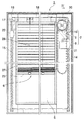
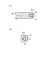
図1は、本発明のブラインド内蔵複層ガラスの実施形態の正面図、図2は、右側面図である。
本発明のブラインド内蔵複層ガラス(1)は、複層ガラス(2)、すなわちスペーサ(3)を介して隔置したガラス板(4a)(4b)構造における密閉された内部空間(5)内に内蔵したブラインド(6)を、前記内部空間(5)の外部に設けたブラインド操作装置(7)におけるチェーン(8)を操作して、開閉させるようになっている。
【0020】
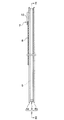
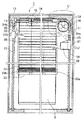
図3は、図2におけるIII〜III線縦断面図である。
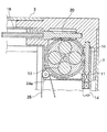
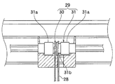
図4は、図1におけるIV〜IV線縦断面図、図5は、図3における破線円V内の部分拡大図である。
【0021】
前記ブラインド操作装置(7)は、操作用のチェーン(8)と、このチェーン(8)によって回転されるプーリー(9)と、プーリーカバー(10)とよりなる。
複層ガラス(2)の内部空間(5)には、前記プーリー(9)と対面する位置に、ウォームギア(11)が設けられている。
【0022】
図4、図5に示すように、前記プーリー(9)とウォームギア(11)とが、一方のガラス板(4a)を介して、相互に対面する面には、相互に吸引する磁石(12)(13)が埋め込まれている。
これらの磁石(12)(13)の吸引力により、プーリー(9)の回転に従って、ウォームギア(11)が連動回転するようになっている。
【0023】
ブラインド(6)の左右には、ブラインド開閉制御用のスクリュー軸(14)(15)が、上下方向に設けられている。
【0024】
図3において、右側のスクリュー軸(14)の上端には、ウォームホイール(16)が一体的に取り付けられており、ウォームギア(11)と噛合している。
一方、左側のスクリュー軸(15)の上端には、傘歯車(17)が一体的に取り付けられており、この傘歯車(17)は、ブラインド(6)の上方に水平方向に配設した伝動回転軸(18)の左端に同じく一体的に取り付けられた傘歯車(19)と噛合している。
【0025】
伝動回転軸(18)の右端には、ウォームホイール(20)が一体的に取り付けられ、ウォームギア(11)と噛合している。
左右のスクリュー軸(14)(15)には、それぞれ昇降管(21)(22)が、遊嵌状態で螺合されている。
【0026】
図6の(a)、(b)図は、それぞれ図3におけるVI(a)〜VI(a)線横断面図、VI(b)〜VI(b)線横断面図である。
昇降管(21)(22)をスクリュー軸(14)(15)に遊嵌状態で螺合させるには、昇降管(21)(22)における雌ねじの歯底および歯先と、スクリュー軸(14)(15)における雄ねじの歯先および歯底とを、相当程度の間隙を保持して螺合させる形態以外に、図6の(a)(b)図に示すように、たとえば昇降管(21)(22)に連続した雌ねじを設けることなく、スクリュー軸(14)(15)における雄ねじの歯丈よりも高さの低い少数の突起、たとえば内側向きに放射状に配置された3個の突起(21a)(22a)を設け、この突起をスクリュー軸(14)(15)の雄ねじに螺合させる形態も推奨される。
【0027】
昇降管(21)(22)をスクリュー軸(14)(15)に遊嵌状態で螺合させることによって、スクリュー軸(14)(15)の回転にともなって、昇降管(21)(22)を上下移動させることが容易となる。
【0028】
各昇降管(21)(22)は、ブラインド(6)の下端部におけるボトムレール(23)の右端(23a)または左端(23b)と、固定滑車(24a)(24b)を介して、紐状物(25)によって連結されている。
右側のスクリュー軸(14)に螺合された昇降管(21)には、錘(26)が取り付けられている。
【0029】
ブラインド(6)の下端部を上下移動させて開閉する際の機構は、次のとおりである。
図1において、ブラインド操作装置(7)におけるチェーン(8)を操作して、プーリー(9)を時計回りに回転させる。このプーリー(9)の回転にともない、一方のガラス板(4a)を介して対面する、図3に示すウォームギア(11)が、磁石の吸引力により、同じく時計回りに回転する。
【0030】
ウォームギア(11)の時計回りの回転により、これと噛合しているウォームホイール(16)を介して、右側のスクリュー軸(14)が平面視において、反時計回りに回転する。このスクリュー軸(14)の回転にともない、昇降管(21)が下向きに移動する。すなわち、昇降管(21)は、紐状物(25)によって固定滑車(24a)を介して、ブラインド(6)におけるボトムレール(23)と連結されて、ボトムレール(23)やスラット(27)の重量が負荷されているとともに、昇降管(21)の左右幅が、内部空間(5)の前後幅よりも大きいため、スクリュー軸(14)の回転に連動して回転することができない。そのため昇降管(21)は、スクリュー軸(14)の回転にともない、下向きに移動する。
昇降管(21)の下向きの移動は、ボトムレール(23)を上向きに移動させるように作用する。
【0031】
一方、ウォームギア(11)の時計回りの回転により、これと噛合しているウォームホイール(20)を介して、伝動回転軸(18)が右側面視において、時計回りに回転する。この伝動回転軸(18)の時計回りの回転により、2つの傘歯車(19)(17)を介して、左側のスクリュー軸(15)が平面視において時計回りに回転する。このスクリュー軸(15)の回転にともない、昇降管(22)が下向きに移動する。昇降管(22)の下向きの移動は、ボトムレール(23)を上向きに移動させるように作用する。
【0032】
このように、左右の昇降管(21)(22)が同時に下向きに移動し、ボトムレール(23)を上向きに移動させるように作用するため、ボトムレール(23)は水平状態を保持しながら、上向きに移動し、ブラインド(6)を下端部から順次、上部に向けて折り畳むようにして、開いた状態とすることができる。
【0033】
ブラインド(6)のボトムレール(23)を所望の位置まで上方に移動させて開いた状態とした後に、チェーン(8)の操作によるプーリー(9)の回転を停止すれば、ボトムレール(23)は、その位置で保持される。すなわち、スクリュー軸(14)(15)には、ブラインド(6)を構成する複数のスラット(27)のうち、ボトムレール(23)とともに、上方に移動させて持ち上げたスラット(27)の重量と、錘(26)の重量のうち、錘として作用する有効重量との差にほぼ相当する力が負荷されて、スクリュー軸(14)(15)を回転させようとするが、ウォームホイール(16)(20)からウォームギア(11)への回転の伝動が不可能なため、ボトムレール(23)の移動は、上下方向いずれについても阻止されて、ボトムレール(23)は定位置を保持する。
【0034】
また、ボトムレール(23)を上方に移動させてブラインド(6)を開いた状態から、再びボトムレール(23)を下方に移動させてブラインド(6)を閉じる際には、チェーン(8)を操作して、ブラインド(6)を開く場合とは逆向きに、プーリー(9)を回転させればよい。
【0035】
本発明のブラインド内蔵複層ガラスは、スクリュー軸(14)に噛合させた昇降管(21)に錘(26)を取り付け、この錘(26)とボトムレール(23)を紐状物(25)を介して連結していることが大きな特徴である。
【0036】
このような機構とすることにより、ブラインド(6)を、ボトムレール(23)を上下方向に移動させて開閉する際のウォームギア(11)を回転させるために必要な力が大幅に減少する。すなわち、このウォームギア(11)を回転させるために必要な力は、ブラインド(6)を開閉する際に、上下方向に移動させるスラット(27)とボトムレール(23)との総重量と、錘(26)の重量のうち、錘として作用する有効重量との差に、スクリュー軸(14)(15)、伝動回転軸(18)、ウォームギア(11)、ウォームホイール(20)、傘歯車(17)(19)等の機構における回転摩擦力を加えたものである。
【0037】
然るに、前記錘(26)の重量のうち、錘として作用する有効重量を、前記スラット(27)とボトムレール(23)との総重量とほぼ等しくなるように調節することにより、これらの差をほぼ零に近くすることができる。
なお、ここで錘として作用する有効重量とは、錘(26)を取り付けた昇降管(21)がスクリュー軸(14)に噛合しているため、バランサーとして有効に作用するのは、錘の重量の数割であり、このバランサーとして作用する重量を称する。
【0038】
このため、ウォームギア(11)を回転させるために必要な力は、実質的に前記機構における回転摩擦力だけとなる。この回転摩擦力は、元来、小さいものである。したがって、ウォームギア(11)を回転させるために必要な力は、小さい力で充分である。
【0039】
このため、チェーン(8)を操作して、プーリー(9)を回転させ、このプーリー(9)の回転に従って、磁石の吸引力を介してウォームギア(11)を連動して回転させる際に、ウォームギア(11)には、小さい前記摩擦力しか負荷されていないため、前記ウォームギア(11)の連動回転が確実に行われる。
【0040】
また、本実施形態では、錘(26)を、左右の昇降管(21)(22)のうち、一方の昇降管(21)にのみ取り付けたが、両方の昇降管(21)(22)に取り付けてもよい。
この場合は、両方の昇降管(21)(22)に取り付けた錘の重量のうち、錘として作用する有効重量の和が、前記スラット(27)とボトムレール(23)との総重量とほぼ等しくなるように調節すればよい。
なお、昇降管(21)(22)の重量が大きい場合、たとえば、左右の昇降管(21)(22)の有効総重量が、前記スラット(27)とボトムレール(23)との総重量とほぼ等しい場合などは、昇降管(21)(22)が実質的に錘(26)の作用をもなすため、別途錘(26)を取り付けることは不要である。
この実施形態も、本明細書においては、昇降管(21)(22)に錘(26)を取り付けた一実施形態として取扱う。
【0041】
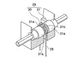
図7は、図3における破線円VII内の部分拡大図、図8は、図7の部分斜視図である。
ブラインド(6)は、側面視において、上下方向に並ぶ各スラット(27)を水平になるように位置させたときの各スラット(27)のブラインド表側縁同士、ブラインド裏側内同士をラダーコード(28)で連結し、下端にボトムレール(23)を取り付けて形成されている。
【0042】
各スラット(27)の縦方向から水平方向までの角度を調節することにより、ブラインド(6)の開閉を制御することができる。
【0043】
伝動回転軸(18)には、スラット角度調節部(29)が設けられている。スラット角度調節部(29)は、スプリングクラッチ(30)と、このスプリングクラッチ(30)の取付部(31)とよりなる。
【0044】
スプリングクラッチ(30)は、コイルばねの両端をそれぞれ上向きに折り曲げて、前記ラダーコード(28)の係止部(30a)を設けて形成されている。
【0045】
取付部(31)は、伝動回転軸(18)を、2段に拡径するとともに、その最大拡径部(31a)の中央において、1段に縮径して縮径部(31b)を形成してある。スプリングクラッチ(30)は、前記縮径部(31b)に緊縛に外嵌されている。
【0046】
スプリングクラッチ(30)は、ラダーコード(28)の上端を係止する各係止部(30a)(30b)を、ブラインド(6)の表と裏側に配置させ、ブラインド(6)の表側に位置する係止部(30a)には、各スラット(27)のブラインド表側縁同士を連結するラダーコード(28)の上端を、ブラインド(6)の裏側に位置する係止部(30b)には、各スラット(27)のブラインド裏側縁同士を連結するラダーコード(28)の上端を、それぞれ係止させてある。
【0047】
チェーン(8)を操作して、プーリー(9)を回転させ、同時にウォームギア(11)を連動回転させながら、ボトムレール(23)を上下方向に移動させている間は、スプリングクラッチ(30)は摺動して、伝動回転軸(18)の回転に連動回転せず、ボトムレール(23)の上下方向の移動を止めた際には、スプリングクラッチ(30)は、伝動回転軸(18)の回転に連動回転して、ブラインド(6)におけるスラット(27)の開度の角度調節により開閉制御をなし得るようになっている。
【0048】
すなわち、たとえば、ボトムレール(23)を所望の位置まで、上方に移動させた後に、チェーン(8)の操作を一旦止め、次いで伝動回転軸(18)を半回転以内の範囲で、わずかに回転させるようにチェーン(8)を操作することにより、スプリングクラッチ(30)が、伝動回転軸(18)の回転に連動回転して、スラット(27)の開度の角度調節がなされる。
【0049】
【発明の効果】
本発明によれば、次のような効果が奏せられる。
(1) 請求項1記載の発明によれば、本発明のブラインド内蔵複層ガラスにおけるブラインドは、巻き上げ式でないため、一般の複層ガラスとして、最も多用されている空気層の厚さが12mmの複層ガラス内に、ブラインドを内蔵させることができる。
このため空気層の厚さが大きい場合に生ずるコーキング材の破損による結露等の不都合を防止することができるとともに、標準タイプの市販サッシに容易に取り付けることができる。
さらに、錘を利用して、ウォームギアに負荷される力を軽減しているため、ブラインドのボトムレールを上下方向に移動させて開閉する際に、チェーンの操作に対するボトムレールの上下方向の追従移動性が良好であり、操作性に優れる。
【0050】
(2) 請求項2記載の発明によれば、比較的簡単な機構で、上記(1)項に記載の効果が奏せられる発明を構成することができるとともに、ウォームギアとウォームホイールの組合わせによって、ボトムレールを上下方向の所望の位置で安定的に保持して、ブラインドの開き程度を調節することができる。
【0051】
(3) 請求項3記載の発明によれば、密閉空間内部に収容されたウォームギアを、外部に設けたブラインド操作装置によって、効率よく連動回転させることができる。
【0052】
(4) 請求項4記載の発明によれば、スクリュー軸の回転に従って、昇降管を容易に上下方向に移動させることができる。
【0053】
(5) 請求項5記載の発明によれば、比較的にコンパクトなブラインド内蔵複層ガラスを得ることができる。
【0054】
(6) 請求項6記載の発明によれば、ブラインドにおける部品の中で、最も重いボトムレールを、固定滑車を介して昇降管と紐状物によって連結することにより、ボトムレールを上下方向に移動させて行うブラインドの開閉操作を円滑にすることができる。
【0055】
(7) 請求項7記載の発明によれば、ボトムレールを上下方向に移動させてブラインドを開閉する際のウォームギアに負荷される力を最小限にして、チェーンを操作して回転させるプーリーに対する前記ウォームギアの連動回転性を高め、操作性を優れたものとすることができる。
【0056】
(8) 請求項8記載の発明によれば、スラットの開度の角度調節を効果的に行うことができる。
【0057】
(9) 請求項9記載の発明によれば、内部空間における結露を効果的に防止し、複層ガラスの曇りを防ぎ、かつブラインドの開閉機構の湿気による耐用期間の短縮を防止することができる。
【0058】
(10) 請求項10記載の発明によれば、本発明のブラインド内蔵複層ガラスを、標準タイプの市販サッシに容易に取り付けることができる。
【図面の簡単な説明】
【図1】本発明のブラインド内蔵複層ガラスの実施形態の正面図である。
【図2】同じく、右側面図である。
【図3】図2におけるIII〜III線縦断面図である。
【図4】図1におけるIV〜IV線縦断面図である。
【図5】図3における破線円V内の部分拡大図である。
【図6】(a)、(b)図は、それぞれ図3におけるVI(a)〜VI(a)線横断面図、VI(b)〜VI(b)線横断面図である。
【図7】図3における破線円VII内の部分拡大図である。
【図8】図7の部分斜視図である。
【符号の説明】
(1)ブラインド内蔵複層ガラス
(2)複層ガラス
(3)スペーサ
(4a)(4b)ガラス板
(5)内部空間
(6)ブラインド
(7)ブラインド操作装置
(8)チェーン
(9)プーリー
(10)プーリーカバー
(11)ウォームギア
(12)(13)磁石
(14)(15)スクリュー軸
(16)ウォームホイール
(17)傘歯車
(18)伝動回転軸
(19)傘歯車
(20)ウォームホイール
(21)(22)昇降管
(21a)(22a)突起
(23)ボトムレール
(23a)左端
(23b)右端
(24a)(24b)固定滑車
(25)紐状物
(26)錘
(27)スラット
(28)ラダーコード
(29)スラット角度調節部
(30)スプリングクラッチ
(30a)(30b)係止部
(31)取付部
(31a)最大拡径部
(31b)縮径部[0001]
TECHNICAL FIELD OF THE INVENTION
The present invention relates to a double glazing having a built-in blind.
[0002]
[Prior art]
In recent years, the use of double-glazed glass has increased in general houses, offices, schools, and the like because of its excellent heat-insulating and sound-insulating effects.
Some roll-up blinds are built into the double-glazed glass, but in this case, the thickness of the air layer in the double-glazed glass needs to be about 29 mm or more because of the so-called thickening of the roll.
[0003]
Generally, the internal space of the double-glazed glass has a closed structure in order to prevent dew condensation. Therefore, when the air layer becomes thicker as described above, the air expands thermally due to a change in air temperature, and as a result, the caulking material that seals around the glass plate is damaged, the hermetic structure is damaged, and dew condensation occurs. The disadvantage is that it occurs.
[0004]
In the case of a double glazing having an air layer thickness of 29 mm, the total thickness becomes 35 mm when the thickness of each glass plate is added to 3 mm, and the depth dimension becomes excessively large. Can not be attached to
[0005]
On the other hand, in order to avoid winding thickening, an elevating bar is attached to the lower end of the blind, an internal magnet piece is provided at both ends or one end of the elevating bar, and an external magnet piece that is engaged with the internal magnet piece is moved up and down to move up and down. There has been proposed an invention in which a bar is moved to follow an external magnet piece (Patent Document 1).
[0006]
However, in this invention, since the lower end of the blind is directly lifted by the attraction of the magnet, there is a problem that the inner magnet piece may not follow the outer magnet piece due to the weight of the lifting bar or slat in the blind.
[0007]
[Patent Document 1]
JP-A-8-313267
(See especially claim 1 and FIG. 1).
[0008]
[Problems to be solved by the invention]
In view of the above-mentioned situation, the present invention, in the case where the thickness of the air layer is large, is to incorporate a blind in a double-layer glass having a thickness of 12 mm, which is the most frequently used air layer, as a general double-layer glass. In addition to preventing inconvenience such as dew condensation due to damage to the caulking material, it can be attached to a standard type of commercially available sash, and when opening and closing the lower end of the blind by moving it vertically, the vertical direction of the lower end of the blind for operation The object of the present invention is to provide a double-glazed glass with a built-in blind which has good follow-up mobility and excellent operability.
[0009]
[Means for Solving the Problems]
According to the present invention, the above-mentioned problem is solved as follows.
(1) A blind is built in the internal space between the glass plates separated by a spacer, and a screw shaft for controlling the opening and closing of the blind is vertically arranged on the left and right sides of the blind, and provided outside the internal space. A worm gear that rotates in conjunction with the pulling force of the magnet in the blind operating device according to the attraction of the magnet is provided in the internal space, and the worm gear directly or indirectly indirectly via the transmission rotating shaft interlocks with the worm gear. By rotating, the up and down pipes respectively screwed to this screw shaft are moved up and down, and the left and right up and down pipes are connected to the lower end of the blind by a string-like object via fixed pulleys, respectively, and A weight is attached to at least one of the elevating pipes, and the weight of the weight is used to rotate the screw shaft interlockingly. A double-glazed glass with built-in blinds, characterized in that the driving force required to rotate the worm gear is reduced.
[0010]
(2) In the above item (1), of the left and right screw shafts, for one of the screw shafts, a worm wheel provided on the screw shaft is meshed with the worm gear. A worm wheel provided at one end of the transmission rotating shaft disposed on the worm gear is meshed with the worm gear, and a bevel gear provided at the other end is meshed with a bevel gear provided at one end of the screw shaft to rotate the worm gear. This allows the left and right screw shafts to rotate in conjunction.
[0011]
(3) In the above item (1) or (2), the blind operating device is formed by a pulley on which a magnet is attached and a chain that rotates the pulley, and the pulley is formed of one glass of a double glazing. The worm gear is opposed to the worm gear via a plate, and a magnet is attached to the worm gear. The attraction force of both magnets in the pulley and the worm gear causes the worm gear to rotate in conjunction with the rotation of the pulley.
[0012]
(4) In any one of the above items (1) to (3), the elevating pipes respectively screwed to the left and right screw shafts are screwed in a loosely fitted state.
[0013]
(5) In any one of the above items (1) to (4), a screw shaft meshed directly with the worm gear, without passing through a transmission rotary shaft, of the elevating tube meshed with the left and right screw shafts. Weight shall be attached only to the elevating pipe meshed with.
[0014]
(6) In any one of the above items (1) to (5), the left and right elevating pipes are respectively connected to a bottom rail of a blind by a string through fixed pulleys.
[0015]
(7) In any one of the above items (1) to (6), when opening and closing the blind, the slat and the bottom rail in the blind are moved in the vertical direction, and are attached to the left and right lifting pipes or one of them. Of the weight of the weight, the effective weight acting as the weight is adjusted to be substantially equal.
[0016]
(8) The spring clutch according to any one of the above items (2) to (7), wherein each of the two ends of the coil spring is disposed on the front and rear sides of the blind, respectively, on the transmission rotating shaft disposed horizontally. When the front and rear ladder cords for connecting the slats of the blind are connected to each end of the spring clutch, and the lower end of the blind is moved vertically, the spring clutch is used. Slides, does not rotate in conjunction with the rotation of the transmission rotary shaft, when the vertical movement of the lower end of the blind is stopped, the spring clutch rotates in conjunction with the rotation of the transmission rotary shaft. The opening and closing control can be performed by adjusting the angle of the slat opening in the blind.
[0017]
(9) In any one of the above items (1) to (8), the internal space formed between the glass plates separated by the spacer is a closed space.
[0018]
(10) In any one of the above items (1) to (9), an inner dimension between the glass plates separated by the spacer is approximately 12 mm.
[0019]
BEST MODE FOR CARRYING OUT THE INVENTION
FIG. 1 is a front view of an embodiment of a double-glazed glass with built-in blinds of the present invention, and FIG. 2 is a right side view.
The double glazing with built-in blinds (1) of the present invention comprises a double glazing (2), that is, a closed internal space (5) in a glass plate (4a) (4b) structure separated by a spacer (3). The blind (6) built in the interior is opened and closed by operating a chain (8) in a blind operating device (7) provided outside the internal space (5).
[0020]
FIG. 3 is a vertical sectional view taken along line III-III in FIG.
4 is a vertical sectional view taken along the line IV-IV in FIG. 1, and FIG. 5 is a partially enlarged view in a broken circle V in FIG.
[0021]
The blind operating device (7) includes an operating chain (8), a pulley (9) rotated by the chain (8), and a pulley cover (10).
A worm gear (11) is provided in the internal space (5) of the double glazing (2) at a position facing the pulley (9).
[0022]
As shown in FIGS. 4 and 5, the pulley (9) and the worm gear (11) have magnets (12) that attract each other on the surfaces facing each other via one glass plate (4a). (13) is embedded.
By the attraction force of these magnets (12) and (13), the worm gear (11) rotates in conjunction with the rotation of the pulley (9).
[0023]
Screw shafts (14) and (15) for controlling the opening and closing of the blind are provided on the left and right sides of the blind (6) in the vertical direction.
[0024]
In FIG. 3, a worm wheel (16) is integrally attached to the upper end of the right screw shaft (14), and meshes with the worm gear (11).
On the other hand, a bevel gear (17) is integrally attached to the upper end of the left screw shaft (15), and the bevel gear (17) is a transmission arranged horizontally above the blind (6). It meshes with a bevel gear (19) also integrally attached to the left end of the rotating shaft (18).
[0025]
A worm wheel (20) is integrally attached to the right end of the transmission rotation shaft (18), and meshes with the worm gear (11).
Elevating pipes (21) and (22) are loosely fitted to the left and right screw shafts (14) and (15), respectively.
[0026]
6A and 6B are a cross-sectional view taken along line VI (a) -VI (a) and a cross-sectional view taken along line VI (b) -VI (b) in FIG. 3, respectively.
In order to screw the hoisting pipes (21) and (22) into the screw shafts (14) and (15) in a loosely fitted state, the bottom and tooth tips of the internal threads in the hoisting pipes (21) and (22) and the screw shaft (14) are used. 6) As shown in FIGS. 6A and 6B, for example, in addition to the form in which the tip and the bottom of the external thread are screwed together with a considerable gap in (15), as shown in FIGS. ) Without a continuous internal thread on (22), a small number of projections which are lower than the tooth length of the external thread on the screw shafts (14), (15), for example three projections radially arranged inward ( It is also recommended to provide 21a) and (22a) and screw the projections to the external threads of the screw shafts (14) and (15).
[0027]
By screwing the lifting pipes (21) and (22) into the screw shafts (14) and (15) in a loosely fitted state, the rotation of the screw shafts (14) and (15) causes the lifting pipes (21) and (22) to rotate. Can be easily moved up and down.
[0028]
Each of the hoisting pipes (21) and (22) is in a string form via the right end (23a) or the left end (23b) of the bottom rail (23) at the lower end of the blind (6) and fixed pulleys (24a) (24b). Connected by an object (25).
A weight (26) is attached to a lifting pipe (21) screwed to the right screw shaft (14).
[0029]
The mechanism for opening and closing the lower end of the blind (6) by vertically moving it is as follows.
In FIG. 1, the chain (8) in the blind operating device (7) is operated to rotate the pulley (9) clockwise. With the rotation of the pulley (9), the worm gear (11) shown in FIG. 3 facing via one glass plate (4a) also rotates clockwise by the attraction of the magnet.
[0030]
The clockwise rotation of the worm gear (11) causes the right screw shaft (14) to rotate counterclockwise in plan view via the worm wheel (16) meshing therewith. With the rotation of the screw shaft (14), the lifting pipe (21) moves downward. That is, the hoisting pipe (21) is connected to the bottom rail (23) of the blind (6) via the fixed pulley (24a) by the string-like object (25), and the bottom rail (23) and the slat (27) are connected. And the right and left width of the elevating pipe (21) is larger than the front and rear width of the internal space (5), so that it cannot rotate in conjunction with the rotation of the screw shaft (14). Therefore, the lifting pipe (21) moves downward with the rotation of the screw shaft (14).
The downward movement of the hoisting pipe (21) acts to move the bottom rail (23) upward.
[0031]
On the other hand, the clockwise rotation of the worm gear (11) causes the transmission rotating shaft (18) to rotate clockwise in right side view via the worm wheel (20) meshing therewith. The clockwise rotation of the transmission rotation shaft (18) causes the left screw shaft (15) to rotate clockwise in plan view via the two bevel gears (19) and (17). With the rotation of the screw shaft (15), the lifting pipe (22) moves downward. The downward movement of the hoisting tube (22) acts to move the bottom rail (23) upward.
[0032]
As described above, since the left and right lifting pipes (21) and (22) simultaneously move downward and act to move the bottom rail (23) upward, the bottom rail (23) maintains a horizontal state while maintaining a horizontal state. It can be moved upward and the blinds (6) can be folded upward from the lower end, so that they can be opened.
[0033]
After the bottom rail (23) of the blind (6) is moved upward to a desired position and opened, and then the rotation of the pulley (9) by the operation of the chain (8) is stopped, the bottom rail (23) Is held in that position. That is, the screw shafts (14) and (15) have the weight of the slats (27) lifted by moving upward together with the bottom rail (23) among the plurality of slats (27) constituting the blind (6). Of the weight of the weight (26), a force substantially corresponding to the difference from the effective weight acting as a weight is applied to rotate the screw shafts (14) and (15), but the worm wheel (16) Since the transmission of rotation from (20) to the worm gear (11) is impossible, the movement of the bottom rail (23) is prevented in both the vertical direction, and the bottom rail (23) maintains a fixed position.
[0034]
When the blind (6) is closed by moving the bottom rail (23) downward again from the state in which the blind (6) is opened by moving the bottom rail (23) upward, the chain (8) must be moved. By operating the pulley (9), the pulley (9) may be rotated in a direction opposite to the direction in which the blind (6) is opened.
[0035]
In the double-glazed glass with built-in blind of the present invention, a weight (26) is attached to an elevating tube (21) meshed with a screw shaft (14), and the weight (26) and the bottom rail (23) are connected to a string (25). It is a great feature that they are connected via a.
[0036]
With such a mechanism, the force required to rotate the worm gear (11) when the blind (6) is opened and closed by moving the bottom rail (23) in the vertical direction is greatly reduced. That is, the force required to rotate the worm gear (11) depends on the total weight of the slat (27) and the bottom rail (23), which are moved up and down when opening and closing the blind (6), and the weight ( Among the weights of 26), the difference from the effective weight acting as a weight is different from the screw shafts (14) (15), the transmission rotating shaft (18), the worm gear (11), the worm wheel (20), and the bevel gear (17). The rotational friction force in the mechanism such as (19) is added.
[0037]
However, by adjusting the effective weight acting as a weight out of the weight of the weight (26) so as to be substantially equal to the total weight of the slats (27) and the bottom rail (23), these differences are reduced. It can be close to zero.
Here, the effective weight acting as a weight means that the lifting pipe (21) to which the weight (26) is attached is meshed with the screw shaft (14). And the weight acting as the balancer.
[0038]
Therefore, the only force required to rotate the worm gear (11) is substantially the rotational friction force of the mechanism. This rotational friction force is inherently small. Therefore, a small force is sufficient for rotating the worm gear (11).
[0039]
For this reason, the chain (8) is operated to rotate the pulley (9). When the worm gear (11) is rotated in conjunction with the rotation of the pulley (9) through the attraction force of the magnet, the worm gear is rotated. Since only a small frictional force is applied to (11), the interlocking rotation of the worm gear (11) is reliably performed.
[0040]
Further, in the present embodiment, the weight (26) is attached to only one of the right and left lifting pipes (21) and (22), but the weight (26) is attached to both lifting and lowering pipes (21) and (22). May be attached.
In this case, of the weights of the weights attached to both the lifting pipes (21) and (22), the sum of the effective weights acting as the weights is almost equal to the total weight of the slats (27) and the bottom rail (23). What is necessary is just to adjust so that it may become equal.
When the weight of the lifting pipes (21) and (22) is large, for example, the effective total weight of the left and right lifting pipes (21) and (22) is equal to the total weight of the slats (27) and the bottom rail (23). In the case where the weights are substantially equal to each other, since the lifting pipes (21) and (22) substantially function as the weight (26), it is unnecessary to separately attach the weight (26).
This embodiment is also handled in the present specification as one embodiment in which the weight (26) is attached to the lifting pipes (21) and (22).
[0041]
FIG. 7 is a partially enlarged view in a broken circle VII in FIG. 3, and FIG. 8 is a partial perspective view of FIG.
When the blinds (6) are positioned such that the slats (27) arranged in the vertical direction are horizontal in a side view, the ladder cords (28) are formed between the front edges of the blinds of the slats (27) and the insides of the backs of the blinds. ), And a bottom rail (23) is attached to the lower end.
[0042]
By adjusting the angle of each slat (27) from the vertical direction to the horizontal direction, the opening and closing of the blind (6) can be controlled.
[0043]
The transmission rotation shaft (18) is provided with a slat angle adjusting section (29). The slat angle adjusting section (29) includes a spring clutch (30) and a mounting section (31) for the spring clutch (30).
[0044]
The spring clutch (30) is formed by bending both ends of a coil spring upward to provide a locking portion (30a) for the ladder cord (28).
[0045]
The attachment part (31) expands the diameter of the transmission rotary shaft (18) in two stages and reduces the diameter of the transmission rotary shaft (18) in one step at the center of the largest diameter part (31a) to form a reduced diameter part (31b). I have. The spring clutch (30) is tightly fitted to the reduced diameter portion (31b).
[0046]
The spring clutch (30) has the locking portions (30a) and (30b) for locking the upper end of the rudder cord (28) on the front and back sides of the blind (6), and is located on the front side of the blind (6). The upper end of the ladder cord (28) connecting the front side edges of the blinds of the respective slats (27) to the locking portion (30a), and the locking portion (30b) located on the back side of the blind (6) has the The upper ends of the ladder cords (28) connecting the back side edges of the blinds of the respective slats (27) are locked.
[0047]
While operating the chain (8) to rotate the pulley (9) and simultaneously rotate the worm gear (11), while moving the bottom rail (23) up and down, the spring clutch (30) When the bottom rail (23) stops sliding in the vertical direction without sliding in synchronization with the rotation of the transmission rotation shaft (18), the spring clutch (30) causes the transmission rotation shaft (18) to rotate. Opening / closing control can be performed by adjusting the opening angle of the slat (27) in the blind (6) in conjunction with the rotation.
[0048]
That is, for example, after the bottom rail (23) is moved upward to a desired position, the operation of the chain (8) is temporarily stopped, and then the transmission rotary shaft (18) is slightly rotated within a range of half a rotation. By operating the chain (8) so as to cause the rotation, the spring clutch (30) rotates in conjunction with the rotation of the transmission rotating shaft (18), and the opening angle of the slat (27) is adjusted.
[0049]
【The invention's effect】
According to the present invention, the following effects can be obtained.
(1) According to the first aspect of the present invention, since the blind in the double-glazing unit with a built-in blind of the present invention is not a roll-up type, the thickness of the air layer most frequently used as a general double-layer glass is 12 mm. Blinds can be built in the double glazing.
For this reason, it is possible to prevent inconvenience such as dew condensation due to breakage of the caulking material that occurs when the thickness of the air layer is large, and it can be easily attached to a standard type commercially available sash.
Furthermore, since the weight applied to the worm gear is reduced by using the weight, when the bottom rail of the blind is moved up and down to open and close, the bottom rail can follow the chain operation in the vertical direction. Is good and the operability is excellent.
[0050]
(2) According to the second aspect of the invention, it is possible to configure the invention having the effects described in the above (1) with a relatively simple mechanism, and to use a combination of a worm gear and a worm wheel. In addition, the bottom rail can be stably held at a desired position in the vertical direction, and the degree of opening of the blind can be adjusted.
[0051]
(3) According to the third aspect of the present invention, the worm gear accommodated in the closed space can be efficiently interlocked and rotated by the blind operating device provided outside.
[0052]
(4) According to the invention described in claim 4, the lifting pipe can be easily moved in the vertical direction according to the rotation of the screw shaft.
[0053]
(5) According to the invention described in claim 5, a relatively compact double-glazed glass with a built-in blind can be obtained.
[0054]
(6) According to the invention as set forth in claim 6, among the parts of the blind, the heaviest bottom rail is connected to the elevating tube and the string-like object via the fixed pulley to move the bottom rail in the vertical direction. The blind opening / closing operation performed in this manner can be performed smoothly.
[0055]
(7) According to the invention as set forth in claim 7, the force applied to the worm gear when the bottom rail is moved up and down to open and close the blind is minimized, and the pulley for rotating the chain by operating the chain is provided. The interlocking rotation of the worm gear can be enhanced, and the operability can be improved.
[0056]
(8) According to the invention described in claim 8, the angle of the slat opening can be effectively adjusted.
[0057]
(9) According to the ninth aspect of the present invention, it is possible to effectively prevent dew condensation in the internal space, prevent fogging of the double glazing, and prevent shortening of the service life of the blind opening and closing mechanism due to moisture. .
[0058]
(10) According to the invention as set forth in claim 10, the double-glazed glass with built-in blind of the present invention can be easily attached to a standard type commercially available sash.
[Brief description of the drawings]
FIG. 1 is a front view of an embodiment of a double-glazed glass with built-in blinds of the present invention.
FIG. 2 is also a right side view.
FIG. 3 is a vertical sectional view taken along line III-III in FIG. 2;
FIG. 4 is a vertical sectional view taken along line IV-IV in FIG. 1;
FIG. 5 is a partially enlarged view in a broken circle V in FIG. 3;
FIGS. 6A and 6B are a cross-sectional view taken along line VI (a) -VI (a) and a cross-sectional view taken along line VI (b) -VI (b) in FIG. 3, respectively.
FIG. 7 is a partially enlarged view in a broken circle VII in FIG. 3;
FIG. 8 is a partial perspective view of FIG. 7;
[Explanation of symbols]
(1) Double-glazed glass with built-in blind (2) Double-glazed glass (3) Spacer (4a) (4b) Glass plate (5) Internal space (6) Blind (7) Blind operating device (8) Chain (9) Pulley ( 10) Pulley cover (11) Worm gear (12) (13) Magnet (14) (15) Screw shaft (16) Worm wheel (17) Bevel gear (18) Transmission rotating shaft (19) Bevel gear (20) Worm wheel ( 21) (22) Lifting pipe (21a) (22a) Projection (23) Bottom rail (23a) Left end (23b) Right end (24a) (24b) Fixed pulley (25) String (26) Weight (27) Slat ( 28) Rudder cord (29) Slat angle adjusting part (30) Spring clutch (30a) (30b) Locking part (31) Mounting part (31a) Largest diameter part (31b) Small diameter part