WO2019044302A1 - 空調ユニット - Google Patents
空調ユニット Download PDFInfo
- Publication number
- WO2019044302A1 WO2019044302A1 PCT/JP2018/028141 JP2018028141W WO2019044302A1 WO 2019044302 A1 WO2019044302 A1 WO 2019044302A1 JP 2018028141 W JP2018028141 W JP 2018028141W WO 2019044302 A1 WO2019044302 A1 WO 2019044302A1
- Authority
- WO
- WIPO (PCT)
- Prior art keywords
- air
- air conditioning
- conditioning unit
- opening
- outlet
- Prior art date
Links
Images


Classifications
-
- B—PERFORMING OPERATIONS; TRANSPORTING
- B60—VEHICLES IN GENERAL
- B60H—ARRANGEMENTS OF HEATING, COOLING, VENTILATING OR OTHER AIR-TREATING DEVICES SPECIALLY ADAPTED FOR PASSENGER OR GOODS SPACES OF VEHICLES
- B60H1/00—Heating, cooling or ventilating [HVAC] devices
- B60H1/00007—Combined heating, ventilating, or cooling devices
- B60H1/00021—Air flow details of HVAC devices
- B60H1/00035—Air flow details of HVAC devices for sending an air stream of uniform temperature into the passenger compartment
- B60H1/00057—Air flow details of HVAC devices for sending an air stream of uniform temperature into the passenger compartment the air being heated and cooled simultaneously, e.g. using parallel heat exchangers
-
- B—PERFORMING OPERATIONS; TRANSPORTING
- B60—VEHICLES IN GENERAL
- B60H—ARRANGEMENTS OF HEATING, COOLING, VENTILATING OR OTHER AIR-TREATING DEVICES SPECIALLY ADAPTED FOR PASSENGER OR GOODS SPACES OF VEHICLES
- B60H1/00—Heating, cooling or ventilating [HVAC] devices
- B60H1/00007—Combined heating, ventilating, or cooling devices
- B60H1/00021—Air flow details of HVAC devices
- B60H1/00064—Air flow details of HVAC devices for sending air streams of different temperatures into the passenger compartment
-
- B—PERFORMING OPERATIONS; TRANSPORTING
- B60—VEHICLES IN GENERAL
- B60H—ARRANGEMENTS OF HEATING, COOLING, VENTILATING OR OTHER AIR-TREATING DEVICES SPECIALLY ADAPTED FOR PASSENGER OR GOODS SPACES OF VEHICLES
- B60H1/00—Heating, cooling or ventilating [HVAC] devices
- B60H1/34—Nozzles; Air-diffusers
- B60H1/3407—Nozzles; Air-diffusers providing an air stream in a fixed direction, e.g. using a grid or porous panel
-
- B—PERFORMING OPERATIONS; TRANSPORTING
- B60—VEHICLES IN GENERAL
- B60S—SERVICING, CLEANING, REPAIRING, SUPPORTING, LIFTING, OR MANOEUVRING OF VEHICLES, NOT OTHERWISE PROVIDED FOR
- B60S1/00—Cleaning of vehicles
- B60S1/02—Cleaning windscreens, windows or optical devices
- B60S1/023—Cleaning windscreens, windows or optical devices including defroster or demisting means
-
- B—PERFORMING OPERATIONS; TRANSPORTING
- B60—VEHICLES IN GENERAL
- B60H—ARRANGEMENTS OF HEATING, COOLING, VENTILATING OR OTHER AIR-TREATING DEVICES SPECIALLY ADAPTED FOR PASSENGER OR GOODS SPACES OF VEHICLES
- B60H1/00—Heating, cooling or ventilating [HVAC] devices
- B60H1/00007—Combined heating, ventilating, or cooling devices
- B60H1/00021—Air flow details of HVAC devices
- B60H2001/00078—Assembling, manufacturing or layout details
- B60H2001/00092—Assembling, manufacturing or layout details of air deflecting or air directing means inside the device
-
- B—PERFORMING OPERATIONS; TRANSPORTING
- B60—VEHICLES IN GENERAL
- B60H—ARRANGEMENTS OF HEATING, COOLING, VENTILATING OR OTHER AIR-TREATING DEVICES SPECIALLY ADAPTED FOR PASSENGER OR GOODS SPACES OF VEHICLES
- B60H1/00—Heating, cooling or ventilating [HVAC] devices
- B60H1/00007—Combined heating, ventilating, or cooling devices
- B60H1/00021—Air flow details of HVAC devices
- B60H2001/00114—Heating or cooling details
- B60H2001/00135—Deviding walls for separate air flows
-
- B—PERFORMING OPERATIONS; TRANSPORTING
- B60—VEHICLES IN GENERAL
- B60H—ARRANGEMENTS OF HEATING, COOLING, VENTILATING OR OTHER AIR-TREATING DEVICES SPECIALLY ADAPTED FOR PASSENGER OR GOODS SPACES OF VEHICLES
- B60H1/00—Heating, cooling or ventilating [HVAC] devices
- B60H1/00007—Combined heating, ventilating, or cooling devices
- B60H1/00021—Air flow details of HVAC devices
- B60H2001/0015—Temperature regulation
- B60H2001/00164—Temperature regulation with more than one by-pass
-
- B—PERFORMING OPERATIONS; TRANSPORTING
- B60—VEHICLES IN GENERAL
- B60H—ARRANGEMENTS OF HEATING, COOLING, VENTILATING OR OTHER AIR-TREATING DEVICES SPECIALLY ADAPTED FOR PASSENGER OR GOODS SPACES OF VEHICLES
- B60H1/00—Heating, cooling or ventilating [HVAC] devices
- B60H1/00507—Details, e.g. mounting arrangements, desaeration devices
- B60H2001/006—Noise reduction
Definitions
- the present disclosure relates to an air conditioning unit for a vehicle.
- Patent Document 1 discloses an air-mixing type air conditioning unit.
- the air conditioning unit sends the temperature-adjusted conditioned air into the vehicle compartment by mixing the cold air generated by the cooler and the warm air generated by the heater.
- the space for mixing cold air and warm air has become smaller inside the air conditioning unit. For this reason, the warm air and the cold air are blown out from the air outlet provided in the vehicle compartment without being sufficiently mixed. As a result, the temperature variation of the blowing air blown out from the outlet is large at one outlet.
- the space for mixing the cold air and the warm air is small, when it is desired to blow air having the same target temperature from the plurality of air outlets, the temperature difference between the air from the plurality of air outlets is large. That is, the temperature variation of the blowing air between the outlets in the plurality of outlets is large.
- An object of the present disclosure is to provide an air conditioning unit capable of reducing the temperature variation of the blowing air at one outlet and reducing the temperature variation of the blowing air between the outlets at the plurality of outlets. I assume. Another object of the present disclosure is to provide an air conditioning unit capable of reducing the noise of the blowing air.
- the air conditioning unit An air conditioning case having a blowout opening for blowing out air; A cooler, provided inside the air conditioning case, for cooling the air directed to the blowout opening; A heater provided inside the air conditioning case and heating air directed to the blowout opening; An adjustment component provided in the blowout opening for adjusting an air flow passing through the blowout opening; The adjustment component is formed with a first region through which air flows and a second region where the resistance to air flow is greater than that of the first region.
- the air flow passing through the blowout opening can be disturbed. Therefore, when the warm air generated by the heater and the cold air generated by the cooler flow toward the blowout opening, the warm air and the cold air can be mixed by the adjustment component. Therefore, it becomes possible to reduce the temperature variation of the blowing wind in one blower outlet.
- the adjustment component in the blowout opening, the resistance to air flow of the blowout opening provided with the adjustment component can be adjusted.
- at least one outlet opening is provided with an adjustment component.
- the mixing ratio of the warm air and the cold air between the outlets in the plurality of outlets can be adjusted. Therefore, the mixing ratio of the warm air and the cold air between the outlets is adjusted so that the temperature variation of the blown air between the outlets at the plurality of outlets is reduced. Thereby, it becomes possible to reduce the temperature variation of the blowing wind between the outlets in the plurality of outlets.
- the air conditioning unit An air conditioning case having a blowout opening for blowing out air; An adjustment component provided in the blowout opening for adjusting an air flow passing through the blowout opening; The adjustment component has a partition that separates each of the plurality of air passages through which air can pass.
- the partition can rectify the air flow passing through the blowout opening.
- the wind speed distribution of the blow-off wind which blows off from the blower outlet provided in the vehicle interior can be closely approached uniformly.
- the partition can provide resistance to the air flow passing through the blowout opening. As a result, it is possible to reduce the wind volume by reducing the volume of the blown air blown out from the blowout port into the vehicle compartment.
- FIG. 2 is a cross-sectional view taken along line II-II of FIG. It is a perspective view of an air-conditioning unit in a 1st embodiment of a state where adjustment parts are not provided. It is a front view of the adjustment component of 1st Embodiment. It is an enlarged view of the V section of FIG. It is a front view of adjustment parts which changed a part of adjustment parts of a 1st embodiment. It is a front view of the adjustment component of 2nd Embodiment.
- FIG. 7 shows a portion of an adjustment component in another embodiment.
- FIG. 7 shows a portion of an adjustment component in another embodiment.
- the air conditioning unit 10 is a vehicle air conditioning unit that constitutes a part of a vehicle air conditioner.
- the air conditioning unit 10 is mounted on the vehicle front side of the front seat in the vehicle compartment. More specifically, this air conditioning unit 10 is disposed inside the instrument panel.
- the air conditioning unit 10 blows the air that has passed through the heat exchanger toward the vehicle interior.
- the air conditioning unit 10 includes an air conditioning case 12, a blower (not shown), an evaporator 14, a heater core 16, and a PTC heater 18.
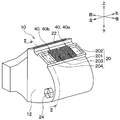
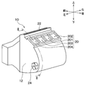
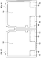
- the air conditioning case 12 constitutes an outer shell of the air conditioning unit 10. As shown in FIG. 1, the air conditioning case 12 is formed with a plurality of blowout openings 20, 22, 24. Each of the plurality of blowout openings 20, 22, 24 is an opening for blowing air from the inside of the air conditioning case 12 to the outside.
- the plurality of blowout openings 20, 22, 24 include a face opening 20, a defroster opening 22 and a foot opening 24.
- the face opening 20 is connected to a face outlet provided in an instrument panel (not shown) via a duct (not shown).
- the defroster opening 22 is connected to a defroster outlet provided in an instrument panel (not shown) via a duct (not shown).
- the face outlet includes a driver's seat center outlet, a driver's seat side outlet, a passenger seat center outlet and a passenger seat side outlet.
- the driver's seat center outlet and the driver's seat side outlet are provided on the driver's side of the instrument panel.
- the front passenger seat air outlet and the passenger side air outlet are provided on the passenger seat side of the instrument panel.
- the driver's seat center outlet and the passenger seat center outlet are provided on the center side of the instrument panel in the lateral direction of the vehicle.
- the driver's seat side outlet and the passenger seat side outlet are provided outside the instrument panel in the left-right direction of the vehicle.
- the face opening 20 includes a driver's seat center opening 201, a driver's seat side opening 202, a passenger's seat center opening 203, and a passenger's seat side opening 204.
- FIG. 3 shows the air conditioning unit 10 in a state in which the adjustment component 40 described later is not provided.
- the driver's seat center opening 201 continues to the driver's seat center outlet.
- the driver's seat side opening 202 is connected to the driver's seat side outlet.
- the front passenger seat center opening 203 is connected to the front passenger seat center outlet.
- the front passenger side opening 204 is connected to the front passenger side air outlet.
- the blower is provided inside the air conditioning case 12.
- the blower forms an air flow toward any of the plurality of blowout openings 20, 22, 24.
- the evaporator 14 is provided inside the air conditioning case 12.
- the evaporator 14 is a cooler that cools air directed to any of the plurality of blowout openings 20, 22, 24.
- the evaporator 14 is a heat exchanger for cooling, which evaporates the refrigerant and cools the air by heat exchange between the air and the refrigerant of the refrigeration cycle.
- the heater core 16 and the PTC heater 18 are provided inside the air conditioning case 12.
- the heater core 16 and the PTC heater 18 are heaters for heating air directed to any of the plurality of blowout openings 20, 22, 24.
- the heater core 16 is a heat exchanger for heating which heats air by heat exchange between the air and the engine coolant.
- the PTC heater 18 is an auxiliary heating device that heats the air that has passed through the heater core 16.
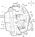
- an air passage 26 through which air flows toward any one of the plurality of blowout openings 20, 22, 24 is formed inside the air conditioning case 12.
- the air passage 26 includes an upper passage 28 located on the upper side inside the air conditioning case 12 and a lower passage 30 located on the lower side inside the air conditioning case 12.
- the upper passage 28 and the lower passage 30 are partitioned by upper and lower partition walls 32 provided in the air conditioning case 12.
- the upper passage 28 includes an upper warm air passage 281, an upper cold air passage 282 and an upper mixing passage 283 formed on the air flow downstream side of the evaporator 14.
- the upper warm air passage 281 guides the warm air generated by the air passing through the upper portion of the heater core 16 to the upper mixing passage 283.
- the upper cold air passage 282 guides the cold air generated by the air passing through the upper portion of the evaporator 14 to the upper mixing passage 283 by bypassing the upper portion of the heater core 16.
- the upper mixing passage 283 guides the mixed air of the warm air from the upper warm air passage 281 and the cold air from the upper cold air passage 282 to the face opening 20 and the defroster opening 22.
- the lower passage 30 includes a lower warm air passage 301, a lower cold air passage 302 and a lower mixing passage 303 formed on the air flow downstream side of the evaporator 14.
- the lower hot air passage 301 guides the warm air generated by the air passing through the lower portion of the heater core 16 to the lower mixing passage 303.
- a PTC heater 18 is disposed in the lower side hot air passage 301. The air that has passed through the lower portion of the heater core 16 is heated by the PTC heater 18.
- the lower cold air passage 302 guides the cold air generated by the air passing through the lower portion of the evaporator 14 to the lower mixing passage 303 by bypassing the lower portion of the heater core 16.
- the lower mixing passage 303 guides the mixed air of the warm air from the lower warm air passage 301 and the cold air from the lower cold air passage 302 to the foot opening 24 shown in FIG.
- the lower mixing passage 303 guides the mixed air of the warm air from the lower warm air passage 301 and the cold air from the lower cold air passage 302 to the upper mixing passage 283 via the communication port 305.
- the communication port 305 is formed in the upper and lower partition walls 32. The communication port 305 causes the upper mixing passage 283 and the lower mixing passage 303 to communicate with each other.
- the air conditioning unit 10 includes an air mix door 34 and a blowout mode door 36.
- the air mix door 34 is a temperature control door that adjusts the mixing ratio of cold air and warm air to adjust the temperature of the air conditioning air.
- the air mix door 34 includes an upper air mix door 341 and a lower air mix door 342.
- the upper air mix door 341 is disposed between the evaporator 14 and the heater core 16 in the upper passage 28.
- the lower air mixing door 342 is disposed between the evaporator 14 and the heater core 16 in the lower passage 30.
- the blowout mode door 36 selectively opens and closes the plurality of blowout openings 20, 22, 24.
- the blowout mode door 36 selectively opens and closes the plurality of blowout openings 20, 22, 24 to realize each blowout mode such as the face mode and the foot mode.
- the blowout mode door 36 includes a face door 361, a defroster door 362, and a foot door 363.
- the foot door 363 is integrated with a door 364 that opens and closes the communication port 305.
- the face door 361 opens the face opening 20.
- the defroster door 362 closes the defroster opening 22.
- the foot door 363 closes the communication passage 304 connected to the foot opening 24 and opens the communication port 305.
- the position of the air mix door 34 is set such that the temperature of the air blown out from the face outlet becomes a desired temperature.
- the warm air from each of the upper warm air passage 281 and the lower warm air passage 301 and the cold air from each of the upper cold air passage 282 and the lower cold air passage 302 are as shown by arrows in FIG. It flows toward the face opening 20 while being mixed in the upper mixing passage 283.
- the wind that has passed through each of the driver's seat center opening 201, the driver's seat side opening 202, the passenger seat center opening 203, and the passenger seat side opening 204 is the driver's seat center outlet, the driver's seat side outlet, and the passenger seat center.
- the air is blown out into the vehicle compartment from each of the air outlet and the passenger side air outlet.
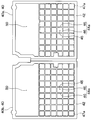
- the air conditioning unit 10 comprises two adjustment parts 40.
- the two adjustment components 40 include a first adjustment component 40 a provided in the driver's seat center opening 201 and a second adjustment component 40 b provided in the passenger seat center opening 203.
- the first adjustment component 40 a adjusts the air flow flowing out of the driver's seat center opening 201.
- the second adjustment component 40 b adjusts the air flow flowing out of the front passenger seat center opening 203.
- the first adjustment component 40a and the second adjustment component 40b are integrated.
- the first adjustment component 40 a is fixed to the driver's seat center opening 201.
- the second adjustment component 40 b is fixed to the front passenger seat center opening 203.
- the first adjustment component 40 a may be fixed to the driver's seat center opening 201 side of a duct connected to the driver's seat center opening 201.
- the second adjustment component 40 b may be fixed to the passenger seat center opening 203 side of the duct connected to the passenger seat center opening 203.
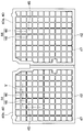
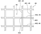
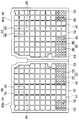
- each of the two adjustment parts 40 has a frame 42 and a grid 44.
- the frame 42 has a shape along the opening edge of the blowout opening where the adjustment component 40 is provided.
- the grid 44 is in the area enclosed by the frame 42.
- the grid 44 is a plurality of linear members 46 arranged to form a plurality of gaps 45.
- the plurality of linear members 46 are reticulated members that form the plurality of gaps 45.
- air can pass through the plurality of gaps 45. Therefore, the plurality of gaps 45 are a plurality of air passing portions through which air can pass.
- the plurality of linear members 46 is a partition that divides each of the plurality of air passing portions. In the present embodiment, the entire area surrounded by the frame 42 is the lattice area 47.
- the plurality of linear members 46 have a plurality of first linear members 461 and a plurality of second linear members 462.
- Each of the plurality of first linear members 461 is disposed spaced apart from one another.
- Each of the plurality of second linear members 462 is disposed spaced apart from one another.
- Each of the plurality of first linear members 461 intersects with each of the plurality of second linear members 462. For this reason, each shape of the plurality of gaps 45 is a square.
- each of the plurality of first linear members 461 and each of the plurality of second linear members 462 are coupled and integrated at an intersection portion 463 where the both intersect each other. As shown in FIG. 6, each of the plurality of first linear members 461 and each of the plurality of second linear members 462 may not be integrated at the intersection portion 463. That is, each of the plurality of first linear members 461 and each of the plurality of second linear members 462 may be knitted.
- the frame 42 and the lattice 44 are configured as an integrally molded product made of resin.
- An integrally molded article is a continuous molded article having no joint.
- the frame 42 and the grid 44 may not be made of resin.
- the air conditioning unit 10 of the present embodiment includes two adjustment components 40. Therefore, the air flow passing through each of the driver's seat center opening 201 and the passenger's seat center opening 203 can be rectified by the grid 44. As a result, the wind speed distribution of the wind blown out from each of the driver's seat center outlet and the passenger seat center outlet can be made to approach uniformly.
- the grid 44 can provide resistance to air flow passing through the driver's seat center opening 201 and the passenger's seat center opening 203, respectively. As a result, the wind volume can be reduced by reducing the volume of the wind blown out from each of the driver's seat center outlet and the passenger seat center outlet.
- the noise of the blowing air can be reduced as compared with the case where the two adjustment components 40 are not provided.
- the thicknesses of the plurality of linear members 46 may be changed, or the intervals between the adjacent linear members 46 may be changed. By making such a change, it is possible to adjust the pressure loss of the air flow passing through each of the driver's seat center opening 201 and the passenger's seat center opening 203 so as to obtain a desired noise reduction effect.
- this embodiment differs from the first embodiment in that the adjustment component 40 has a baffle plate 48.
- the other configuration of the air conditioning unit 10 is the same as that of the first embodiment.
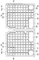
- Each of the two adjustment parts 40 has a frame 42, a grid 44 and two baffles 48.
- the baffle plate 48 is a plate member that obstructs the air flow.
- the grid 44 and the two baffles 48 are disposed in the area surrounded by the frame 42.
- the two baffles 48 are arranged at a part of the periphery of the central part of the area surrounded by the frame 42. Therefore, the baffle plate 48 is biased in the area surrounded by the frame 42.
- the grid 44 is disposed in the area surrounded by the frame 42 except the two baffles 48.
- the frame 42, the lattice 44, and the two baffles 48 are formed of a resin integrally molded product. These may not be made of resin.
- the lattice area 47 in which the lattice 44 is disposed a plurality of gaps 45 are formed.
- the aperture ratio of the lattice region 47 is higher than the aperture ratio of the baffle plate region 49.
- the aperture ratio is the ratio of the gap formed by the member to the entire area in which the member is disposed. If the member does not form a gap, the aperture ratio is 0%. Therefore, the lattice area 47 is an area having lower resistance to air flow than the baffle area 49.
- the baffle area 49 is an area higher in resistance to air flow than the grid area 47.
- the grid 44 is a low resistance member that provides less resistance to air flow as compared to the baffle plate 48.
- the baffle plate 48 is a high resistance member that provides greater resistance to air flow as compared to the grid 44.
- the lattice area 47 corresponds to the first area through which air flows.
- the baffle plate area 49 corresponds to a second area having a greater resistance to air flow than the first area.
- the baffle plate 48 corresponds to a high resistance member that provides greater resistance to air flow than to the air flow in the first region.
- the grid 44 corresponds to a low resistance member that provides less resistance to air flow than to the air flow in the second region.
- the total area of the lattice area 47 including the lattice 44 and the plurality of gaps 45 is half or more of the total opening area of the blowout openings 201 and 203 provided with the adjustment component 40. is there.
- the lattice area 47 is a continuous area.
- the area of the portion of the baffle plate 48 that inhibits the air flow is larger than the average value of the areas of the plurality of gaps 45.
- the same effect as that of the first embodiment can be obtained by the grating 44. Furthermore, according to the present embodiment, the following effects can be obtained.
- the upper mixing passage 283 and the lower mixing passage 303 which are spaces for mixing cold air and warm air, are becoming smaller. Therefore, unlike the present embodiment, when the adjustment component 40 is not provided at the driver's seat center opening 201, the warm air and the cold air are not sufficiently mixed in the face mode, and the driver's seat center opening 201 Pass through. That is, in the driver's seat center opening 201, an area through which the warm air passes and an area through which the cold air passes exist. The warm air and the cold air that have passed through the driver's seat center opening 201 flow through the duct and are blown out from the driver's seat center outlet in this state.
- the adjustment component 40 is provided at the driver's seat center opening 201.
- the adjustment component 40 of the present embodiment has a baffle plate 48.
- the baffle plate region 49 has high resistance to air flow as compared with the region where the baffle plate 48 is not disposed (ie, the lattice region 47). Therefore, the wind flow passing through the driver's seat center opening 201 can be disturbed.
- the baffle plate 48 is disposed in the region on the warm wind side when the adjustment component 40 is not provided in the driver's seat center opening 201. For this reason, when warm air and cold air pass the driver's seat center opening 201 by the baffle plate 48, the warm air can be directed to the cold air side. Thereby, warm air and cold air can be mixed. Therefore, in the driver's seat center outlet, temperature variation in the outlet can be reduced.
- the adjustment component 40 is also provided in the front passenger seat center opening 203. For this reason, also in the front passenger seat center outlet, temperature variation in the outlet can be reduced.
- the upper mixing passage 283 and the lower mixing passage 303 are small and the adjustment component 40 is not provided in the driver's seat center opening 201 and the passenger's seat center opening 203.
- the temperature of the blowing air blown out from the blower outlet is higher in the driver's seat center blower outlet and the passenger seat center blower outlet than in the driver's seat side blower outlet and the passenger seat side blower outlet.
- the adjustment component 40 is provided in each of the driver's seat center opening 201 and the passenger's seat center opening 203 in the face opening 20.
- resistance to warm air is higher in the driver's seat center opening 201 and the passenger's seat center opening 203 than in the case where the adjustment component 40 is not provided. Therefore, the volume of warm air flowing through the driver's seat center opening 201 and the passenger's seat center opening 203 can be reduced, and the volume of warm air flowing through the driver's seat side opening 202 and the passenger seat side opening 204 can be increased.
- the mixing ratio of warm air and cold air passing through each of the driver's seat center opening 201, the driver's seat side opening 202, the assistant's seat center opening 203, and the assistant's seat side opening 204 can be made close.
- the temperatures of the air blown out from the driver's seat center outlet, the driver's seat side outlet, the passenger seat center outlet and the passenger seat side outlet can be made uniform.
- the baffle plate 48 adjusts the resistance to the air flow between the driver's seat center opening 201 and the passenger's seat center opening 203.
- the ease of warm air flow is adjusted in each of the openings 201, 202, 203, 204, and the mixing ratio of cold air and warm air is adjusted.
- the driver's seat center outlet, the passenger seat center outlet, the driver's seat side outlet, and the passenger seat side outlet temperature variations among the outlets can be reduced.
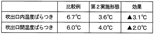
- FIG. 8 shows the test results conducted by the present inventor.
- FIG. 8 shows the measurement results of the temperature variation in the air outlet and the temperature variation between the air outlets in each of the air conditioning unit of the comparative example and the air conditioning unit 10 of this embodiment.
- the air conditioning unit of the comparative example is different from the air conditioning unit 10 of the present embodiment in that each of the two adjustment parts 40 does not have the two baffle plates 48.
- the other configurations of the air conditioning unit of the comparative example are the same as the air conditioning unit 10 of the present embodiment.
- the temperature variation in the outlet is the temperature variation in one face outlet, that is, the outlet at the driver's seat center outlet.
- the temperature variation between the outlets is the temperature variation between the four face outlets: the driver's seat center outlet, the passenger's seat center outlet, the driver's side outlet and the passenger's side outlet.
- the two adjustment parts 40 are parts separate from the air conditioning case 12. Therefore, by changing the number and position of the baffle plates 48 of the adjustment component 40, it is possible to reduce the temperature variation for each vehicle type on which the air conditioning unit 10 is mounted without changing the shape of the air conditioning case 12 Can.
- the two baffle plates 48 are disposed in the peripheral portion of the central portion of the area surrounded by the frame 42.
- the area surrounded by the frame 42 corresponds to the opening area of the blowout opening.
- the wind speed of the passing wind is high at the central portion of the opening area of the blowout opening.
- the wind speed of the passing wind is low.
- the baffle plate 48 is disposed in a region where the wind speed is low in the wind speed distribution of the wind passing through the blowout opening when the adjustment component 40 is not provided. Thereby, temperature variation can be made small, suppressing the fall of the amount of winds, and the aggravation of noise.
- positioning place and number of baffle plates 48 are not limited to this embodiment.
- the arrangement location and number of the baffles 48 can be arbitrarily changed.
- the baffle plate 48 may be disposed at the center of the area surrounded by the frame 42. By changing the area occupied by the baffle plate 48 with respect to the arrangement position of the baffle plate 48 and the area surrounded by the frame 42, the temperature distribution of the air blown out from the blowout port can be adjusted.
- the lattice 44 and the two baffle plates 48 are configured as an integrally molded product.
- the grid 44 and the two baffle plates 48 may be separately configured, and both may be joined.
- a plurality of openings 48 a are formed in each of the two baffle plates 48 in each of the two adjustment components 40.
- the other configuration of the air conditioning unit 10 is the same as that of the first embodiment.
- the plurality of openings 48 a may be formed in the baffle plate 48.
- the opening 48a may be one.
- the shapes of the two adjustment components 40 are different from those of the first embodiment.
- the other configuration of the air conditioning unit 10 is the same as that of the first embodiment.
- Each of the two adjustment parts 40 has a frame 42 and a grid 44a.
- the grating 44a is the same as the grating 44 of the first embodiment.
- the grid 44 a is disposed only in a part of the area surrounded by the frame 42.
- the area excluding the lattice area 47a is a hollow portion.
- the hollow portion 50 is formed in the area excluding the lattice area 47a in the area surrounded by the frame 42.
- the lattice area 47a is an area where the lattice 44a is disposed.
- the cavity 50 is an area where no member is disposed.
- the same effect as that of the first embodiment can be obtained by the grating 44.
- the aperture ratio of the cavity 50 is higher than the aperture ratio of the grating region 47a. Therefore, the cavity 50 is a region having lower resistance to the air flow than the lattice region 47a.
- the lattice area 47 a is an area where the resistance to air flow is higher than that of the cavity 50.
- the grid 44 a is a high resistance member that provides greater resistance to air flow as compared to the cavity 50. Therefore, also in this embodiment, the same effect as that of the second embodiment can be obtained.
- the hollow portion 50 corresponds to the first region through which air flows.
- the lattice area 47a corresponds to a second area having a higher resistance to air flow than the first area.
- the grid 44a corresponds to a high resistance member that provides greater resistance to air flow than to the air flow in the first region.
- the shapes of the two adjustment components 40 are different from those of the first embodiment.
- the other configuration of the air conditioning unit 10 is the same as that of the first embodiment.
- Each of the two adjustment parts 40 has a frame 42 and two baffles 48.
- the two baffles 48 are arranged only in a part of the area surrounded by the frame 42.
- the area excluding the baffle plate area 49 is a hollow portion.
- the hollow portion 50 is formed in the area excluding the baffle plate area 49 in the area surrounded by the frame 42.
- the cavity 50 is an area where no member is disposed.
- the aperture ratio of the hollow portion 50 is higher than the aperture ratio of the baffle plate region 49. Therefore, the hollow portion 50 is a region having lower resistance to air flow than the baffle plate region 49.
- the baffle plate region 49 is a region having a higher resistance to air flow than the hollow portion 50.
- the baffle plate 48 is a high resistance member that provides greater resistance to air flow as compared to the hollow portion 50. Therefore, also in this embodiment, the same effect as that of the second embodiment can be obtained.
- the hollow portion 50 corresponds to the first region through which air flows.
- the baffle plate area 49 corresponds to a second area having a greater resistance to air flow than the first area.
- the baffle plate 48 corresponds to a high resistance member that provides greater resistance to air flow than to the air flow in the first region.
- the shapes of the two adjustment components 40 are different from those in the first embodiment.
- the other configuration of the air conditioning unit 10 is the same as that of the first embodiment.
- Each of the two adjustment parts 40 has a frame 42, a first grating 44 and a second grating 52.
- the first grating 44 and the second grating 52 are arranged in the area surrounded by the frame 42.
- the first grating 44 is the same as the grating 44 of the second embodiment.
- the first grating region 47 in which the first grating 44 is disposed is the same as the grating region 47 of the second embodiment.
- the second grating 52 is, like the first grating 44, a plurality of linear members 46 arranged to form a plurality of gaps 45.
- the distance between the adjacent linear members 46 is narrower than that of the first grating 44.
- Adjacent linear members 46 are densely arranged. For this reason, in the second grating 52, each of the plurality of gaps 45 is smaller than the first grating 44.
- the same effect as that of the first embodiment can be obtained by the first grating 44 and the second grating 52.
- the aperture ratio of the first grating region 47 is higher than the aperture ratio of the second grating region 53 in which the second grating 52 is disposed.
- the first lattice area 47 is an area having a lower resistance to air flow than the second lattice area 53.
- the second lattice area 53 is an area having higher resistance to air flow than the first lattice area 47.
- the first grid 44 is a low resistance member that provides less resistance to air flow as compared to the second grid 52.
- the second grid 52 is a high resistance member that provides greater resistance to air flow as compared to the first grid 44. Therefore, also in this embodiment, the same effect as that of the second embodiment can be obtained.
- the first lattice area 47 corresponds to the first area through which air flows.
- the second lattice area 53 corresponds to a second area having a higher resistance to air flow than the first area.
- the second grid 52 corresponds to a high resistance member that provides greater resistance to air flow than to the air flow in the first region.
- the first grid 44 corresponds to a low resistance member that provides less resistance to air flow than to the air flow in the second region.
- each of the plurality of gaps 45 formed by the grating 44, the first grating 44, and the second grating 52 has a square shape.
- the shape of each of the plurality of gaps may be another shape other than a square.
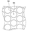
- each of the grid 44, the first grid 44, and the second grid 52 may be changed to a mesh member 54 forming a plurality of circular gaps 55.
- the plurality of circular gaps 55 are a plurality of air passing portions through which air can pass.
- the mesh member 54 is a partition that divides each of the plurality of air passing portions.
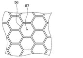
- each of the grid 44, the first grid 44, and the second grid 52 may be changed to a net-like member 56 forming a plurality of hexagonal gaps 57.
- the plurality of hexagonal gaps 57 are a plurality of air passage portions through which air can pass.
- the mesh member 56 is a partition that divides each of the plurality of air passing portions.
- the adjustment component 40 is provided only in two of the four openings 201, 202, 203, 204 of the face opening 20.
- the present invention is not limited to this case, and one or more of the four openings 201, 202, 203, 204 may be provided.
- the adjustment component 40 may be provided in all four openings 201, 202, 203, 204.
- the adjustment component 40 is provided in the face opening 20.
- the adjustment component 40 may be provided in another blowout opening. Thereby, the same effect as each of the above embodiments can be obtained.
- the air conditioning unit includes an air conditioning case, a cooler, a heater, and an adjustment component.
- the adjustment component is formed with a first region through which air flows and a second region where the resistance to air flow is greater than that of the first region.
- the second region is provided with a high resistance member that provides greater resistance to air flow than the first region.
- the resistance to air flow in the second region can be greater than the resistance to air flow in the first region.
- the low resistance member is provided in the first region to provide a smaller resistance to the air flow than the second region.
- the low resistance member can be provided in the first region.
- the low resistance member is a partition that divides each of the plurality of air passing portions through which air can pass.
- the high resistance member is a plate member having a portion that obstructs the air flow.
- the members described in the fourth aspect can be used as the low resistance member and the high resistance member.
- the partition can rectify the air flow passing through the blowout opening.
- the wind speed distribution of the blow-off wind which blows off from the blower outlet provided in the vehicle interior can be closely approached uniformly.
- the partition can provide resistance to the air flow passing through the blowout opening. As a result, it is possible to reduce the wind volume by reducing the volume of the blown air blown out from the blowout port into the vehicle compartment.
- the air conditioning unit includes the air conditioning case and the adjustment component.
- the adjustment component has a partition that separates each of the plurality of air passages through which air can pass.
Landscapes
- Engineering & Computer Science (AREA)
- Mechanical Engineering (AREA)
- Physics & Mathematics (AREA)
- Thermal Sciences (AREA)
- Air-Conditioning For Vehicles (AREA)
Abstract
空調ユニット(10)は、空気を吹き出す吹出開口部(201、203)が形成された空調ケース(12)と、空調ケースの内部に設けられ、吹出開口部に向かう空気を冷却する冷却器と、空調ケースの内部に設けられ、吹出開口部に向かう空気を加熱する加熱器と、吹出開口部に設けられ、吹出開口部を通過する空気流れを調整する調整部品(40)とを備える。調整部品には、空気が流れる第1領域と、前記第1領域よりも空気流れに対する抵抗が大きな第2領域とが形成されている
Description
本出願は、2017年8月30日に出願された日本特許出願番号2017-165846号に基づくもので、ここにその記載内容が参照により組み入れられる。
本開示は、車両用の空調ユニットに関するものである。
特許文献1にエアミックス方式の空調ユニットが開示されている。この空調ユニットは、冷却器で生成した冷風と、加熱器で生成した暖風とを混合することで、温度調整した空調風を車室内に送る。
近年、空調ユニットの小型化により、空調ユニットの内部において、冷風と暖風とを混合するスペースが小さくなっている。このため、暖風と冷風とが、十分に混合されずに、車室内に設けられた吹出口から吹き出される。この結果、1つの吹出口において、吹出口から吹き出される吹出風の温度ばらつきが大きい。また、冷風と暖風とを混合するスペースが小さいと、同じ目標温度の吹出風を複数の吹出口から吹き出したいときに、複数の吹出口のそれぞれからの吹出風の温度差が大きい。すなわち、複数の吹出口における吹出口間の吹出風の温度ばらつきが大きい。
また、空調ユニットでは、車室内に設けられた吹出口から車室内に吹き出される吹出風の騒音の低減が求められている。
また、空調ユニットでは、車室内に設けられた吹出口から車室内に吹き出される吹出風の騒音の低減が求められている。
本開示は、1つの吹出口における吹出風の温度ばらつきの低減が可能であって、複数の吹出口における吹出口間の吹出風の温度ばらつきの低減が可能である空調ユニットを提供することを目的とする。また、本開示は、吹出風の騒音を低減できる空調ユニットを提供することを他の目的とする。
上記目的を達成するため、本開示の1つの観点によれば、
空調ユニットは、
空気を吹き出す吹出開口部が形成された空調ケースと、
空調ケースの内部に設けられ、吹出開口部に向かう空気を冷却する冷却器と、
空調ケースの内部に設けられ、吹出開口部に向かう空気を加熱する加熱器と、
吹出開口部に設けられ、吹出開口部を通過する空気流れを調整する調整部品とを備え、
調整部品には、空気が流れる第1領域と、第1領域よりも空気流れに対する抵抗が大きな第2領域とが形成されている。
空調ユニットは、
空気を吹き出す吹出開口部が形成された空調ケースと、
空調ケースの内部に設けられ、吹出開口部に向かう空気を冷却する冷却器と、
空調ケースの内部に設けられ、吹出開口部に向かう空気を加熱する加熱器と、
吹出開口部に設けられ、吹出開口部を通過する空気流れを調整する調整部品とを備え、
調整部品には、空気が流れる第1領域と、第1領域よりも空気流れに対する抵抗が大きな第2領域とが形成されている。
これによれば、調整部品が設けられていない場合と比較して、吹出開口部を通過する風流れを乱すことができる。このため、加熱器で生成された暖風と冷却器で生成された冷風とが吹出開口部に向かって流れるとき、調整部品によって暖風と冷風とを混合させることができる。よって、1つの吹出口における吹出風の温度ばらつきを低減することが可能となる。
また、吹出開口部に調整部品を設けることで、調整部品が設けられた吹出開口部の空気流れに対する抵抗を調整することができる。吹出開口部が複数ある場合、少なくとも1つの吹出開口部に、調整部品が設けられる。これにより、複数の吹出口における吹出口間の暖風と冷風との混合割合を調整することができる。そこで、複数の吹出口における吹出口間の吹出風の温度ばらつきが低減されるように、吹出口間の暖風と冷風との混合割合を調整する。これにより、複数の吹出口における吹出口間の吹出風の温度ばらつきを低減することが可能となる。
また、本開示の別の観点によれば、
空調ユニットは、
空気を吹き出す吹出開口部が形成された空調ケースと、
吹出開口部に設けられ、吹出開口部を通過する空気流れを調整する調整部品とを備え、
調整部品は、空気が通過できる複数の空気通過部のそれぞれを仕切る仕切りを有する。
空調ユニットは、
空気を吹き出す吹出開口部が形成された空調ケースと、
吹出開口部に設けられ、吹出開口部を通過する空気流れを調整する調整部品とを備え、
調整部品は、空気が通過できる複数の空気通過部のそれぞれを仕切る仕切りを有する。
これによれば、仕切りによって、吹出開口部を通過する空気流れを整流することができる。これにより、車室内に設けられた吹出口から吹き出される吹出風の風速分布を均一に近づけることができる。さらに、仕切によって、吹出開口部を通過する空気流れに対して抵抗をつけることができる。これにより、吹出口から車室内に吹き出される吹出風の風量を低減させ、風速を低下させることができる。
これらの結果、調整部品が設けられていない場合と比較して、吹出風の騒音を低減することができる。
なお、各構成要素等に付された括弧付きの参照符号は、その構成要素等と後述する実施形態に記載の具体的な構成要素等との対応関係の一例を示すものである。
以下、本開示の実施形態について図に基づいて説明する。なお、以下の各実施形態相互において、互いに同一もしくは均等である部分には、同一符号を付して説明を行う。
(第1実施形態)
まず、図1、2に示す本実施形態の空調ユニット10の全体の概略構成について説明する。空調ユニット10は、車両用空調装置の一部を構成する車両用空調ユニットである。この空調ユニット10は、車室内のうち前席よりも車両前方側に搭載される。より具体的には、この空調ユニット10は、インストルメントパネルの内側に配置される。空調ユニット10は、熱交換器を通過した空気を車室内に向けて吹き出す。
まず、図1、2に示す本実施形態の空調ユニット10の全体の概略構成について説明する。空調ユニット10は、車両用空調装置の一部を構成する車両用空調ユニットである。この空調ユニット10は、車室内のうち前席よりも車両前方側に搭載される。より具体的には、この空調ユニット10は、インストルメントパネルの内側に配置される。空調ユニット10は、熱交換器を通過した空気を車室内に向けて吹き出す。
空調ユニット10は、空調ケース12と、図示しない送風機と、蒸発器14と、ヒータコア16と、PTCヒータ18とを備える。
空調ケース12は、空調ユニット10の外殻を構成する。図1に示すように、空調ケース12には、複数の吹出開口部20、22、24が形成されている。複数の吹出開口部20、22、24のそれぞれは、空調ケース12の内部から外部へ空気を吹き出すための開口部である。複数の吹出開口部20、22、24は、フェイス開口部20、デフロスタ開口部22およびフット開口部24を含む。フェイス開口部20は、図示しないダクトを介して、図示しないインストルメントパネルに設けられたフェイス吹出口に連なっている。デフロスタ開口部22は、図示しないダクトを介して、図示しないインストルメントパネルに設けられたデフロスタ吹出口に連なっている。
フェイス吹出口は、運転席センタ吹出口、運転席サイド吹出口、助手席センタ吹出口および助手席サイド吹出口を含む。運転席センタ吹出口および運転席サイド吹出口は、インストルメントパネルのうち運転席側に設けられている。助手席センタ吹出口および助手席サイド吹出口は、インストルメントパネルのうち助手席側に設けられている。運転席センタ吹出口および助手席センタ吹出口は、インストルメントパネルのうち車両左右方向の中央側に設けられている。運転席サイド吹出口および助手席サイド吹出口は、インストルメントパネルのうち車両左右方向の外側に設けられている。
図1、3に示すように、フェイス開口部20は、運転席センタ開口部201、運転席サイド開口部202、助手席センタ開口部203および助手席サイド開口部204を含む。図3は、後述する調整部品40を設けていない状態の空調ユニット10を示している。
図示しないが、運転席センタ開口部201は、運転席センタ吹出口に連なっている。運転席サイド開口部202は、運転席サイド吹出口に連なっている。助手席センタ開口部203は、助手席センタ吹出口に連なっている。助手席サイド開口部204は、助手席サイド吹出口に連なっている。
送風機は、空調ケース12の内部に設けられる。送風機は、複数の吹出開口部20、22、24のいずれかに向かう空気流れを形成する。
蒸発器14は、空調ケース12の内部に設けられる。蒸発器14は、複数の吹出開口部20、22、24のいずれかに向かう空気を冷却する冷却器である。蒸発器14は、空気と冷凍サイクルの冷媒との熱交換によって、冷媒を蒸発させるとともに、空気を冷却する冷却用の熱交換器である。
ヒータコア16およびPTCヒータ18は、空調ケース12の内部に設けられる。ヒータコア16およびPTCヒータ18は、複数の吹出開口部20、22、24のいずれかに向かう空気を加熱する加熱器である。ヒータコア16は、空気とエンジン冷却水との熱交換によって、空気を加熱する加熱用の熱交換器である。PTCヒータ18は、ヒータコア16を通過した空気を加熱する補助暖房装置である。
図2に示すように、空調ケース12の内部には、複数の吹出開口部20、22、24のいずれかに向かって空気が流れる空気通路26が形成されている。空気通路26は、空調ケース12の内部における上側に位置する上側通路28と、空調ケース12の内部における下側に位置する下側通路30とを含む。上側通路28と下側通路30とは、空調ケース12に設けられた上下仕切壁32によって仕切られている。
上側通路28には、蒸発器14の上側部分と、ヒータコア16の上側部分とが配置されている。上側通路28は、蒸発器14の空気流れ下流側に形成された上側温風通路281、上側冷風通路282および上側混合通路283を含む。
上側温風通路281は、空気がヒータコア16の上側部分を通過することによって生成された温風を上側混合通路283に導く。上側冷風通路282は、空気が蒸発器14の上側部分を通過することによって生成された冷風を、ヒータコア16の上側部分を迂回させて上側混合通路283に導く。上側混合通路283は、上側温風通路281からの温風と上側冷風通路282からの冷風との混合風をフェイス開口部20およびデフロスタ開口部22に導く。
下側通路30には、蒸発器14の下側部分と、ヒータコア16の下側部分と、PTCヒータ18とが配置されている。下側通路30は、蒸発器14の空気流れ下流側に形成された下側温風通路301、下側冷風通路302および下側混合通路303を含む。
下側温風通路301は、空気がヒータコア16の下側部分を通過することによって生成された温風を下側混合通路303に導く。下側温風通路301には、PTCヒータ18が配置されている。ヒータコア16の下側部分を通過した空気は、PTCヒータ18によって加熱される。下側冷風通路302は、空気が蒸発器14の下側部分を通過することによって生成された冷風を、ヒータコア16の下側部分を迂回させて下側混合通路303に導く。下側混合通路303は、下側温風通路301からの温風と下側冷風通路302からの冷風との混合風を、連通路304を介して図1に示すフット開口部24に導く。また、下側混合通路303は、下側温風通路301からの温風と下側冷風通路302からの冷風との混合風を、連通口305を介して上側混合通路283に導く。連通口305は、上下仕切壁32に形成されている。連通口305は、上側混合通路283と下側混合通路303とを連通させる。
図2に示すように、空調ユニット10は、エアミックスドア34と、吹出モードドア36とを備える。
エアミックスドア34は、冷風と温風との混合割合を調整して空調風の温度を調整する温調用ドアである。エアミックスドア34は、上側エアミックスドア341と、下側エアミックスドア342とを含む。上側エアミックスドア341は、上側通路28のうち蒸発器14とヒータコア16との間に配置されている。下側エアミックスドア342は、下側通路30のうち蒸発器14とヒータコア16との間に配置されている。
吹出モードドア36は、複数の吹出開口部20、22、24を選択的に開閉する。吹出モードドア36が複数の吹出開口部20、22、24を選択的に開閉することで、フェイスモード、フットモードなどの各吹出モードが実現される。吹出モードドア36は、フェイスドア361、デフロスタドア362およびフットドア363を含む。本実施形態では、フットドア363は、連通口305を開閉するドア364と一体化されている。
フェイスモードでは、フェイスドア361がフェイス開口部20を開く。デフロスタドア362がデフロスタ開口部22を塞ぐ。フットドア363が、フット開口部24に連なる連通路304を塞ぐとともに、連通口305を開く。エアミックスドア34は、フェイス吹出口からの吹出風の温度が所望の温度となるように、ドア位置が設定される。
これにより、上側温風通路281および下側温風通路301のそれぞれからの温風と、上側冷風通路282および下側冷風通路302のそれぞれからの冷風とが、図2中の矢印のように、上側混合通路283で混合されながらフェイス開口部20に向かって流れる。運転席センタ開口部201、運転席サイド開口部202、助手席センタ開口部203および助手席サイド開口部204のそれぞれを通過した風が、運転席センタ吹出口、運転席サイド吹出口、助手席センタ吹出口および助手席サイド吹出口のそれぞれから車室内に吹き出される。
次に、図1に示す2つの調整部品40について説明する。図1に示すように、空調ユニット10は、2つの調整部品40を備える。2つの調整部品40は、運転席センタ開口部201に設けられた第1調整部品40aと、助手席センタ開口部203に設けられた第2調整部品40bとを含む。第1調整部品40aは、運転席センタ開口部201から流出する空気流れを調整する。第2調整部品40bは、助手席センタ開口部203から流出する空気流れを調整する。第1調整部品40aと第2調整部品40bとは一体化されている。第1調整部品40aは、運転席センタ開口部201に固定される。第2調整部品40bは、助手席センタ開口部203に固定される。なお、第1調整部品40aは、運転席センタ開口部201に接続されるダクトの運転席センタ開口部201側に固定されていてもよい。第2調整部品40bは、助手席センタ開口部203に接続されるダクトの助手席センタ開口部203側に固定されていてもよい。
図4に示すように、2つの調整部品40のそれぞれは、枠42と格子44とを有する。枠42は、調整部品40が設けられる吹出開口部の開口縁部に沿う形状である。
格子44は、枠42で囲まれた領域内にある。格子44は、複数の隙間45を形成するように配列された複数の線状部材46である。複数の線状部材46は、複数の隙間45を形成する網状の部材である。格子44が配置された格子領域47では、複数の隙間45を空気が通過することができる。したがって、複数の隙間45は、空気が通過できる複数の空気通過部である。複数の線状部材46は、複数の空気通過部のそれぞれを仕切る仕切りである。本実施形態では、枠42で囲まれた領域の全部が格子領域47となっている。
具体的には、図5に示すように、複数の線状部材46は、複数の第1線状部材461と、複数の第2線状部材462とを有する。複数の第1線状部材461のそれぞれは、互いに間をあけて配置されている。複数の第2線状部材462のそれぞれは、互いに間をあけて配置されている。複数の第1線状部材461のそれぞれと、複数の第2線状部材462のそれぞれとが、交差している。このため、複数の隙間45のそれぞれの形状は四角である。
また、複数の第1線状部材461のそれぞれと複数の第2線状部材462のそれぞれとは、両者が交差している交差部463で結合して一体化している。なお、図6に示すように、複数の第1線状部材461のそれぞれと複数の第2線状部材462のそれぞれとは、交差部463で一体化していなくてもよい。すなわち、複数の第1線状部材461のそれぞれと複数の第2線状部材462のそれぞれとが編まれていてもよい。
枠42と格子44とは、樹脂製の一体成形品として構成されている。一体成形品とは、接合部を持たない連続した成形品である。枠42と格子44とは、樹脂製でなくてもよい。
このように、本実施形態の空調ユニット10は、2つの調整部品40を備える。このため、格子44によって運転席センタ開口部201と助手席センタ開口部203とのそれぞれを通過する空気流れを整流することができる。これにより、運転席センタ吹出口と助手席センタ吹出口とのそれぞれから吹き出される吹出風の風速分布を均一に近づけることができる。
さらに、格子44によって運転席センタ開口部201と助手席センタ開口部203とのそれぞれを通過する空気流れに対して抵抗をつけることができる。これにより、運転席センタ吹出口と助手席センタ吹出口とのそれぞれから吹き出される吹出風の風量を低減させ、風速を低下させることができる。
これらの結果、本実施形態の空調ユニット10によれば、2つの調整部品40が設けられていない場合と比較して、吹出風の騒音を低減することができる。
また、本実施形態の空調ユニット10では、複数の線状部材46の太さを変更したり、隣り合う線状部材46の間隔を変更したりしてもよい。このように変更することで、所望の騒音低減効果が得られるように、運転席センタ開口部201と助手席センタ開口部203とのそれぞれを通過する空気流れの圧力損失を調整することができる。
(第2実施形態)
図7に示すように、本実施形態は、調整部品40がじゃま板48を有する点で、第1実施形態と異なる。空調ユニット10のその他の構成は、第1実施形態と同じである。
図7に示すように、本実施形態は、調整部品40がじゃま板48を有する点で、第1実施形態と異なる。空調ユニット10のその他の構成は、第1実施形態と同じである。
2つの調整部品40のそれぞれは、枠42と、格子44と、2つのじゃま板48とを有する。じゃま板48は、空気流れを阻害する板部材である。
格子44と2つのじゃま板48とは、枠42で囲まれた領域内に配置されている。2つのじゃま板48は、枠42で囲まれた領域のうち中央部の周辺部の一部に配置されている。したがって、じゃま板48は、枠42で囲まれた領域において偏って配置されている。格子44は、枠42で囲まれた領域のうち2つのじゃま板48を除く領域に配置されている。枠42と、格子44と、2つのじゃま板48は、樹脂製の一体成形品で構成されている。これらは、樹脂製でなくてもよい。
格子44が配置された格子領域47は、複数の隙間45が形成されている。じゃま板48が配置されたじゃま板領域49は、隙間が形成されていない。このため、格子領域47の開口率は、じゃま板領域49の開口率よりも高い。開口率は、部材が配置された領域全体に対するその部材によって形成されている隙間の割合である。その部材が隙間を形成していない場合、開口率は0%である。したがって、格子領域47は、じゃま板領域49よりも、空気流れに対する抵抗が低い領域である。じゃま板領域49は、格子領域47よりも、空気流れに対する抵抗が高い領域である。格子44は、じゃま板48と比較して、空気流れに対して小さな抵抗を付与する低抵抗部材である。じゃま板48は、格子44と比較して、空気流れに対して大きな抵抗を付与する高抵抗部材である。
本実施形態では、格子領域47が、空気が流れる第1領域に対応する。じゃま板領域49が、第1領域よりも空気流れに対する抵抗が大きな第2領域に対応する。じゃま板48が、第1領域における空気流れに対する抵抗よりも、空気流れに対して大きな抵抗を付与する高抵抗部材に対応する。格子44が、第2領域における空気流れに対する抵抗よりも、空気流れに対して小さな抵抗を付与する低抵抗部材に対応する。
また、本実施形態では、格子44と複数の隙間45とを含む格子領域47の全面積は、調整部品40が設けられた吹出開口部201、203の全開口面積のうち半分以上の大きさである。格子領域47は、一続きの領域となっている。じゃま板48のうち空気流れを阻害する部位の面積は、複数の隙間45のそれぞれの面積の平均値よりも大きい。
本実施形態においても、格子44によって、第1実施形態と同様の効果が得られる。さらに、本実施形態によれば、下記の効果も得られる。
近年、空調ユニット10の小型化により、冷風と暖風とを混合するスペースである上側混合通路283と下側混合通路303とが小さくなっている。このため、本実施形態と異なり、調整部品40が運転席センタ開口部201に設けられていない場合、フェイスモード時に、暖風と冷風とが、十分に混合されずに、運転席センタ開口部201を通過する。すなわち、運転席センタ開口部201は、暖風が通過する領域と冷風が通過する領域とが存在する。運転席センタ開口部201を通過した暖風と冷風とが、その状態のまま、ダクトを流れて運転席センタ吹出口から吹き出される。このため、運転席センタ吹出口から吹き出される吹出風の温度ばらつきが大きいという問題が生じる。すなわち、運転席センタ吹出口において、吹出口内の温度ばらつきが大きいという問題が生じる。温度ばらつきが大きいとは、最小温度と最大温度との差が大きいことを意味する。同様に、調整部品40が助手席センタ開口部203に設けられていない場合も、助手席センタ吹出口において、吹出口内の温度ばらつきが大きいという問題が生じる。
これに対して、本実施形態の空調ユニット10では、運転席センタ開口部201に、調整部品40が設けられている。本実施形態の調整部品40は、じゃま板48を有する。枠42で囲まれた領域のうちじゃま板領域49は、じゃま板48が配置されていない領域(すなわち、格子領域47)と比較して、空気流れに対する抵抗が大きい。このため、運転席センタ開口部201を通過する風流れを乱すことができる。
本実施形態では、運転席センタ開口部201のうち調整部品40が設けられていない場合の暖風側の領域に、じゃま板48が配置されている。このため、じゃま板48によって、暖風と冷風とが運転席センタ開口部201を通過する際に、暖風を冷風側に向かわせることができる。これにより、暖風と冷風とを混合させることができる。よって、運転席センタ吹出口において、吹出口内の温度ばらつきを小さくすることができる。
本実施形態の空調ユニット10では、助手席センタ開口部203にも、調整部品40が設けられている。このため、助手席センタ吹出口においても、吹出口内の温度ばらつきを小さくすることができる。
また、上側混合通路283と下側混合通路303とが小さく、かつ、運転席センタ開口部201と助手席センタ開口部203とに調整部品40が設けられていない場合を想定する。この場合、フェイスモード時に、運転席サイド開口部202および助手席サイド開口部204よりも、運転席センタ開口部201および助手席センタ開口部203の方に暖風が多く流れる。このため、運転席サイド吹出口および助手席サイド吹出口よりも運転席センタ吹出口および助手席センタ吹出口の方が、吹出口から吹き出される吹出風の温度が高くなる。このように、同じ目標温度の吹出風を複数の吹出口から吹き出したいときに、複数の吹出口のそれぞれからの吹出風の温度差が大きいという問題が生じる。すなわち、吹出口間の温度ばらつきが大きいという問題が生じる。
これに対して、本実施形態の空調ユニット10では、フェイス開口部20のうち運転席センタ開口部201と助手席センタ開口部203とのそれぞれに、調整部品40を設けている。これにより、運転席センタ開口部201と助手席センタ開口部203とでは、調整部品40を設けていない場合と比較して、暖風に対する抵抗が高くなっている。このため、運転席センタ開口部201および助手席センタ開口部203を流れる暖風の風量を減らし、運転席サイド開口部202および助手席サイド開口部204を流れる暖風の風量を増やすことができる。これにより、運転席センタ開口部201、運転席サイド開口部202、助手席センタ開口部203および助手席サイド開口部204のそれぞれを通過する暖風と冷風との混合割合を近づけることができる。運転席センタ吹出口、運転席サイド吹出口、助手席センタ吹出口および助手席サイド吹出口のそれぞれから吹き出される吹出風の温度を均一に近づけることができる。
このように、本実施形態では、じゃま板48によって、運転席センタ開口部201と助手席センタ開口部203とのそれぞれの空気流れに対する抵抗を調整している。これにより、各開口部201、202、203、204において、暖風の流れやすさを調整して、冷風と暖風との混合割合を調整している。この結果、運転席センタ吹出口、助手席センタ吹出口、運転席サイド吹出口および助手席サイド吹出口において、吹出口間の温度ばらつきを小さくすることができる。
ここで、図8に、本発明者が行った試験結果を示す。図8は、比較例の空調ユニットと本実施形態の空調ユニット10とのそれぞれにおける吹出口内の温度ばらつきと、吹出口間の温度ばらつきとの測定結果を示している。比較例の空調ユニットは、2つの調整部品40のそれぞれが、2つのじゃま板48を有していない点で、本実施形態の空調ユニット10と異なる。比較例の空調ユニットの他の構成は、本実施形態の空調ユニット10と同じである。吹出口内の温度ばらつきは、1つのフェイス吹出口、すなわち、運転席センタ吹出口における吹出口内の温度ばらつきである。吹出口間の温度ばらつきは、4つのフェイス吹出口、すなわち、運転席センタ吹出口、助手席センタ吹出口、運転席サイド吹出口および助手席サイド吹出口における吹出口間の温度ばらつきである。
図8に示す試験結果より、本実施形態の空調ユニット10によれば、比較例の空調ユニットよりも、吹出口内の温度ばらつきを小さくでき、かつ、吹出口間の温度ばらつきを小さくできることが確認された。
また、本実施形態の空調ユニット10では、2つの調整部品40は、空調ケース12とは別体の部品である。このため、調整部品40のじゃま板48の数および位置を変更することで、空調ケース12の形状の変更を伴わずに、空調ユニット10が搭載される車種ごとに、温度ばらつきの低減を図ることができる。
また、本実施形態の空調ユニット10では、2つのじゃま板48は、枠42で囲まれた領域のうち中央部の周辺部に配置されている。枠42で囲まれた領域は、吹出開口部の開口領域に対応している。調整部品40を設けていない場合において、吹出開口部の開口領域の中央部では、通過する風の風速は高い。吹出開口部の開口領域の周辺部では、通過する風の風速は低い。このため、本実施形態では、調整部品40を設けていない場合に吹出開口部を通過する風の風速分布において風速が低い領域に、じゃま板48が配置されている。これにより、風量の低下および騒音の悪化を抑制しながら、温度ばらつきを小さくすることができる。
なお、じゃま板48の配置場所および数は、本実施形態に限定されない。じゃま板48の配置場所および数は、任意に変更可能である。例えば、枠42で囲まれた領域のうち中央部に、じゃま板48を配置してもよい。じゃま板48の配置場所や、枠42に囲まれた領域に対して、じゃま板48が占める範囲を変更することで、吹出口から吹き出される空気の温度分布を調整することができる。
また、本実施形態では、格子44と2つのじゃま板48とが、一体成形品として構成されていた。しかし、格子44と2つのじゃま板48とが、別体で構成され、両者が接合されていてもよい。
(第3実施形態)
図9に示すように、本実施形態では、2つの調整部品40のそれぞれにおいて、2つのじゃま板48のそれぞれに複数の開口部48aが形成されている。空調ユニット10のその他の構成は、第1実施形態と同じである。
図9に示すように、本実施形態では、2つの調整部品40のそれぞれにおいて、2つのじゃま板48のそれぞれに複数の開口部48aが形成されている。空調ユニット10のその他の構成は、第1実施形態と同じである。
このように、じゃま板48に複数の開口部48aが形成されていてもよい。開口部48aは1つであってもよい。じゃま板48に、1つまたは複数の開口部48aを形成することで、じゃま板領域49における空気流れに対する抵抗を減らすことができる。調整部品40が設けられる吹出開口部の空気流れに対する抵抗を調整することができる。
(第4実施形態)
図10に示すように、本実施形態では、2つの調整部品40の形状が第1実施形態と異なる。空調ユニット10のその他の構成は、第1実施形態と同じである。
図10に示すように、本実施形態では、2つの調整部品40の形状が第1実施形態と異なる。空調ユニット10のその他の構成は、第1実施形態と同じである。
2つの調整部品40のそれぞれは、枠42と、格子44aとを有する。格子44aは、第1実施形態の格子44と同じものである。格子44aは、枠42で囲まれた領域のうち一部の領域のみに配置されている。枠42で囲まれた領域のうち格子領域47aを除く領域は、空洞部となっている。換言すると、2つの調整部品40のそれぞれでは、枠42で囲まれた領域のうち格子領域47aを除く領域に、空洞部50が形成されている。格子領域47aは、格子44aが配置された領域である。空洞部50は、部材が何も配置されていない領域である。
本実施形態においても、格子44によって、第1実施形態と同様の効果が得られる。さらに、本実施形態では、空洞部50の開口率は、格子領域47aの開口率よりも高い。このため、空洞部50は、格子領域47aよりも、空気流れに対する抵抗が低い領域である。格子領域47aは、空洞部50よりも、空気流れに対する抵抗が高い領域である。格子44aは、空洞部50と比較して、空気流れに対して大きな抵抗を付与する高抵抗部材である。よって、本実施形態においても、第2実施形態と同様の効果が得られる。
なお、本実施形態では、空洞部50が、空気が流れる第1領域に対応する。格子領域47aが、第1領域よりも空気流れに対する抵抗が大きな第2領域に対応する。格子44aが、第1領域における空気流れに対する抵抗よりも、空気流れに対して大きな抵抗を付与する高抵抗部材に対応する。
(第5実施形態)
図11に示すように、本実施形態では、2つの調整部品40の形状が第1実施形態と異なる。空調ユニット10のその他の構成は、第1実施形態と同じである。
図11に示すように、本実施形態では、2つの調整部品40の形状が第1実施形態と異なる。空調ユニット10のその他の構成は、第1実施形態と同じである。
2つの調整部品40のそれぞれは、枠42と、2つのじゃま板48とを有する。2つのじゃま板48は、枠42で囲まれた領域のうち一部の領域のみに配置されている。枠42で囲まれた領域のうちじゃま板領域49を除く領域は、空洞部となっている。換言すると、2つの調整部品40のそれぞれでは、枠42で囲まれた領域のうちじゃま板領域49を除く領域に、空洞部50が形成されている。空洞部50は、部材が何も配置されていない領域である。
本実施形態では、空洞部50の開口率は、じゃま板領域49の開口率よりも高い。このため、空洞部50は、じゃま板領域49よりも、空気流れに対する抵抗が低い領域である。じゃま板領域49は、空洞部50よりも、空気流れに対する抵抗が高い領域である。じゃま板48は、空洞部50と比較して、空気流れに対して大きな抵抗を付与する高抵抗部材である。よって、本実施形態においても、第2実施形態と同様の効果が得られる。
なお、本実施形態では、空洞部50が、空気が流れる第1領域に対応する。じゃま板領域49が、第1領域よりも空気流れに対する抵抗が大きな第2領域に対応する。じゃま板48が、第1領域における空気流れに対する抵抗よりも、空気流れに対して大きな抵抗を付与する高抵抗部材に対応する。
(第6実施形態)
図12に示すように、本実施形態では、2つの調整部品40の形状が第1実施形態と異なる。空調ユニット10のその他の構成は、第1実施形態と同じである。
図12に示すように、本実施形態では、2つの調整部品40の形状が第1実施形態と異なる。空調ユニット10のその他の構成は、第1実施形態と同じである。
2つの調整部品40のそれぞれは、枠42と、第1格子44と、第2格子52とを有する。第1格子44と第2格子52とは、枠42で囲まれた領域に配置されている。第1格子44は、第2実施形態の格子44と同じである。第1格子44が配置された第1格子領域47は、第2実施形態の格子領域47と同じである。
第2格子52は、第1格子44と同様に、複数の隙間45を形成するように配列された複数の線状部材46である。第2格子52では、第1格子44よりも、隣り合う線状部材46の間隔が狭い。隣り合う線状部材46が密に配置されている。このため、第2格子52では、第1格子44よりも、複数の隙間45のそれぞれが小さい。
本実施形態においても、第1格子44および第2格子52によって、第1実施形態と同様の効果が得られる。さらに、本実施形態では、第1格子領域47の開口率は、第2格子52が配置された第2格子領域53の開口率よりも高い。このため、第1格子領域47は、第2格子領域53よりも、空気流れに対する抵抗が低い領域である。第2格子領域53は、第1格子領域47よりも、空気流れに対する抵抗が高い領域である。第1格子44は、第2格子52と比較して、空気流れに対して小さな抵抗を付与する低抵抗部材である。第2格子52は、第1格子44と比較して、空気流れに対して大きな抵抗を付与する高抵抗部材である。よって、本実施形態においても、第2実施形態と同様の効果が得られる。
なお、本実施形態では、第1格子領域47が、空気が流れる第1領域に対応する。第2格子領域53が、第1領域よりも空気流れに対する抵抗が大きな第2領域に対応する。第2格子52が、第1領域における空気流れに対する抵抗よりも、空気流れに対して大きな抵抗を付与する高抵抗部材に対応する。第1格子44が、第2領域における空気流れに対する抵抗よりも、空気流れに対して小さな抵抗を付与する低抵抗部材に対応する。
(他の実施形態)
(1)第1-第4、第6実施形態では、格子44、第1格子44、第2格子52によって形成される複数の隙間45のそれぞれの形状が四角形状であった。しかしながら、複数の隙間のそれぞれの形状は、四角形以外の他の形状でもよい。
(1)第1-第4、第6実施形態では、格子44、第1格子44、第2格子52によって形成される複数の隙間45のそれぞれの形状が四角形状であった。しかしながら、複数の隙間のそれぞれの形状は、四角形以外の他の形状でもよい。
例えば、格子44、第1格子44、第2格子52のそれぞれを、図13に示すように、円形状の複数の隙間55を形成している網状の部材54に変更してもよい。この場合、円形状の複数の隙間55が、空気が通過できる複数の空気通過部である。網状の部材54は、複数の空気通過部のそれぞれを仕切る仕切りである。
また、図14に示すように、格子44、第1格子44、第2格子52のそれぞれを、六角形の複数の隙間57を形成している網状の部材56に変更してもよい。この場合、六角形の複数の隙間57が、空気が通過できる複数の空気通過部である。網状の部材56は、複数の空気通過部のそれぞれを仕切る仕切りである。
(2)上記各実施形態では、フェイス開口部20の4つの開口部201、202、203、204のうち2つの開口部201、203のみに、調整部品40を設けた。しかしながら、この場合に限らず、4つの開口部201、202、203、204のいずれか1つ以上に設けてもよい。例えば、4つの開口部201、202、203、204の全部に調整部品40を設けてもよい。この場合、センタ開口部201、203とサイド開口部202、204とで、第2実施形態と同様に、空気流れに対する抵抗の大きさを異ならせることが好ましい。これにより、第2実施形態と同様に、吹出口間の温度ばらつきを小さくすることが可能となる。
(3)上記各実施形態では、フェイス開口部20に調整部品40を設けた。しかしながら、他の吹出開口部に調整部品40を設けてもよい。これにより、上記各実施形態と同様の効果が得られる。
(4)本開示は上記した実施形態に限定されるものではなく、請求の範囲に記載した範囲内において適宜変更が可能であり、様々な変形例や均等範囲内の変形をも包含する。また、上記各実施形態は、互いに無関係なものではなく、組み合わせが明らかに不可な場合を除き、適宜組み合わせが可能である。また、上記各実施形態において、実施形態を構成する要素は、特に必須であると明示した場合および原理的に明らかに必須であると考えられる場合等を除き、必ずしも必須のものではないことは言うまでもない。また、上記各実施形態において、実施形態の構成要素の個数、数値、量、範囲等の数値が言及されている場合、特に必須であると明示した場合および原理的に明らかに特定の数に限定される場合等を除き、その特定の数に限定されるものではない。また、上記各実施形態において、構成要素等の材質、形状、位置関係等に言及するときは、特に明示した場合および原理的に特定の材質、形状、位置関係等に限定される場合等を除き、その材質、形状、位置関係等に限定されるものではない。
(まとめ)
上記各実施形態の一部または全部で示された第1の観点によれば、空調ユニットは、空調ケースと、冷却器と、加熱器と、調整部品とを備える。調整部品には、空気が流れる第1領域と、第1領域よりも空気流れに対する抵抗が大きな第2領域とが形成されている。
(まとめ)
上記各実施形態の一部または全部で示された第1の観点によれば、空調ユニットは、空調ケースと、冷却器と、加熱器と、調整部品とを備える。調整部品には、空気が流れる第1領域と、第1領域よりも空気流れに対する抵抗が大きな第2領域とが形成されている。
また、第2の観点によれば、第2領域には、第1領域よりも空気流れに対して大きな抵抗を付与する高抵抗部材が設けられている。これにより、第2領域の空気流れに対する抵抗を、第1領域の空気流れに対する抵抗よりも大きくできる。
また、第3の観点によれば、第1領域には、第2領域よりも空気流れに対して小さな抵抗を付与する低抵抗部材が設けられている。このように、第1領域に、低抵抗部材を設けることができる。
また、第4の観点によれば、低抵抗部材は、空気が通過できる複数の空気通過部のそれぞれを仕切る仕切りである。高抵抗部材は、空気流れを阻害する部位を有する板部材である。低抵抗部材および高抵抗部材として、具体的には第4の観点に記載の部材を用いることができる。
これによれば、仕切りによって、吹出開口部を通過する空気流れを整流することができる。これにより、車室内に設けられた吹出口から吹き出される吹出風の風速分布を均一に近づけることができる。さらに、仕切によって、吹出開口部を通過する空気流れに対して抵抗をつけることができる。これにより、吹出口から車室内に吹き出される吹出風の風量を低減させ、風速を低下させることができる。
これらの結果、調整部品が設けられていない場合と比較して、吹出風の騒音を低減することができる。
また、第5の観点によれば、空調ユニットは、空調ケースと、調整部品とを備える。調整部品は、空気が通過できる複数の空気通過部のそれぞれを仕切る仕切りを有する。
Claims (5)
- 空調ユニットであって、
空気を吹き出す吹出開口部(201、203)が形成された空調ケース(12)と、
前記空調ケースの内部に設けられ、前記吹出開口部に向かう空気を冷却する冷却器(14)と、
前記空調ケースの内部に設けられ、前記吹出開口部に向かう空気を加熱する加熱器(16、18)と、
前記吹出開口部に設けられ、前記吹出開口部を通過する空気流れを調整する調整部品(40)とを備え、
前記調整部品には、空気が流れる第1領域(47、50)と、前記第1領域よりも空気流れに対する抵抗が大きな第2領域(49、47a、53)とが形成されている空調ユニット。 - 前記第2領域には、前記第1領域よりも空気流れに対して大きな抵抗を付与する高抵抗部材(48、44a、52)が設けられている請求項1に記載の空調ユニット。
- 前記第1領域には、前記第2領域よりも空気流れに対して小さな抵抗を付与する低抵抗部材(44、54、56)が設けられている請求項2に記載の空調ユニット。
- 前記低抵抗部材は、空気が通過できる複数の空気通過部(45、55、57)のそれぞれを仕切る仕切り(44、54、56)であり、
前記高抵抗部材は、空気流れを阻害する部位を有する板部材(48)である請求項3に記載の空調ユニット。 - 空調ユニットであって、
空気を吹き出す吹出開口部(201、203)が形成された空調ケース(12)と、
前記吹出開口部に設けられ、前記吹出開口部を通過する空気流れを調整する調整部品(40)とを備え、
前記調整部品は、空気が通過できる複数の空気通過部(45、55、57)のそれぞれを仕切る仕切り(44、54、56)を有する空調ユニット。
Priority Applications (3)
| Application Number | Priority Date | Filing Date | Title |
|---|---|---|---|
| CN201880055721.9A CN111032385B (zh) | 2017-08-30 | 2018-07-26 | 空调单元 |
| DE112018004833.0T DE112018004833T5 (de) | 2017-08-30 | 2018-07-26 | Klimaanlageinheit |
| US16/788,776 US11613155B2 (en) | 2017-08-30 | 2020-02-12 | Air-conditioning unit |
Applications Claiming Priority (2)
| Application Number | Priority Date | Filing Date | Title |
|---|---|---|---|
| JP2017-165846 | 2017-08-30 | ||
| JP2017165846A JP6915460B2 (ja) | 2017-08-30 | 2017-08-30 | 空調ユニット |
Related Child Applications (1)
| Application Number | Title | Priority Date | Filing Date |
|---|---|---|---|
| US16/788,776 Continuation US11613155B2 (en) | 2017-08-30 | 2020-02-12 | Air-conditioning unit |
Publications (1)
| Publication Number | Publication Date |
|---|---|
| WO2019044302A1 true WO2019044302A1 (ja) | 2019-03-07 |
Family
ID=65526301
Family Applications (1)
| Application Number | Title | Priority Date | Filing Date |
|---|---|---|---|
| PCT/JP2018/028141 WO2019044302A1 (ja) | 2017-08-30 | 2018-07-26 | 空調ユニット |
Country Status (5)
| Country | Link |
|---|---|
| US (1) | US11613155B2 (ja) |
| JP (1) | JP6915460B2 (ja) |
| CN (1) | CN111032385B (ja) |
| DE (1) | DE112018004833T5 (ja) |
| WO (1) | WO2019044302A1 (ja) |
Cited By (2)
| Publication number | Priority date | Publication date | Assignee | Title |
|---|---|---|---|---|
| US20200406710A1 (en) * | 2019-06-28 | 2020-12-31 | Mahle International Gmbh | Hvac-module |
| WO2021209409A1 (fr) * | 2020-04-15 | 2021-10-21 | Valeo Systemes Thermiques | Dispositif de chauffage, ventilation et/ou climatisation pour vehicule automobile |
Citations (5)
| Publication number | Priority date | Publication date | Assignee | Title |
|---|---|---|---|---|
| JPS61145017U (ja) * | 1985-03-01 | 1986-09-06 | ||
| JPH05124432A (ja) * | 1991-11-06 | 1993-05-21 | Nippondenso Co Ltd | 自動車用空気調和装置 |
| KR20040065885A (ko) * | 2003-01-16 | 2004-07-23 | 현대모비스 주식회사 | 차량용 공기조화시스템의 에어 덕트 |
| KR20060072432A (ko) * | 2004-12-23 | 2006-06-28 | 한라공조주식회사 | 자동차용 공조장치 |
| JP2006188193A (ja) * | 2005-01-07 | 2006-07-20 | Calsonic Kansei Corp | 車両用空調装置 |
Family Cites Families (23)
| Publication number | Priority date | Publication date | Assignee | Title |
|---|---|---|---|---|
| IT232350Y1 (it) * | 1994-03-15 | 1999-12-17 | Foggini Progetti | Bocchetta di erogazione dell'aria di climatizzazione di autoveicoli con diffusore e concentratore di flusso selezionabili e singolarmente |
| JP3284058B2 (ja) * | 1996-08-30 | 2002-05-20 | 株式会社ケーヒン | 車両用暖房装置 |
| JP3870530B2 (ja) * | 1998-02-04 | 2007-01-17 | 株式会社デンソー | 車両用空調装置 |
| EP1261480B1 (en) | 2000-01-19 | 2004-10-20 | Saint-Gobain Performance Plastics Corporation | Non-curling reinforced composite membranes with differing opposed faces, methods for producing and their use in varied applications |
| US7927684B2 (en) | 2000-01-19 | 2011-04-19 | Saint-Gobain Performance Plastics Corporation | Low coefficient of friction polymer film |
| US7238102B2 (en) | 2003-02-18 | 2007-07-03 | Delphi Technologies, Inc. | Heating, ventilation, and air conditioning system having a film valve and film for controlling air flow |
| DE10121286A1 (de) * | 2001-04-30 | 2002-10-31 | Valeo Klimasysteme Gmbh | Luftführungsgehäuse |
| JP3879655B2 (ja) * | 2002-11-06 | 2007-02-14 | 株式会社デンソー | 車両空調用天井吹出装置 |
| DE10304548A1 (de) * | 2003-01-16 | 2004-07-29 | König & Hohmann und Otto Lübeck GmbH & Co. KG | Luftverteilungselement |
| DE10331398A1 (de) * | 2003-07-11 | 2005-01-27 | Volkswagen Ag | Luftausströmer mit einer Lochabdeckung |
| DE102004003196A1 (de) | 2004-01-22 | 2005-08-18 | Daimlerchrysler Ag | Belüftungseinrichtung für ein Kraftfahrzeug |
| DE102004057316A1 (de) * | 2004-11-27 | 2006-06-01 | Fischer Automotive Systems Gmbh | Lufteinleitvorrichtung |
| DE102006009577A1 (de) | 2006-02-28 | 2007-09-06 | Behr Gmbh & Co. Kg | Kraftfahrzeug-Belüftungssystem |
| EP1996888B1 (de) * | 2006-03-10 | 2019-07-24 | MAHLE Behr GmbH & Co. KG | Wärmetauscher für ein kraftfahrzeug |
| DE102006026655A1 (de) * | 2006-06-08 | 2007-12-13 | Daimlerchrysler Ag | Kraftfahrzeug-Bauteil mit einem wölbstrukturierten Lochblech |
| FR2912085B1 (fr) * | 2007-02-05 | 2009-04-17 | Bourbon Automobile Soc Par Act | Buse de ventilation pour habitacle de vehicule automobile, notamment pour un appui tete de siege de vehicule automobile |
| DE102008021015A1 (de) | 2007-04-25 | 2008-10-30 | Behr Gmbh & Co. Kg | Vorrichtung zur Mischung von gasförmigen Medien und zum Absperren eines Querschnitts |
| JP2009040304A (ja) * | 2007-08-10 | 2009-02-26 | Denso Corp | 車両用空調装置 |
| KR101481697B1 (ko) * | 2008-09-29 | 2015-01-12 | 한라비스테온공조 주식회사 | 차량용 공조장치 |
| DE102011113446A1 (de) * | 2011-09-14 | 2013-03-14 | Valeo Klimasysteme Gmbh | Fahrzeugklimaanlage |
| WO2013185012A1 (en) * | 2012-06-08 | 2013-12-12 | Johnson Controls Technology Company | Flexible material air vent assembly |
| KR101595244B1 (ko) * | 2012-10-30 | 2016-02-18 | 한온시스템 주식회사 | 차량용 공조장치 |
| JP2017165846A (ja) | 2016-03-15 | 2017-09-21 | アーゼッド・エレクトロニック・マテリアルズ(ルクセンブルグ)ソシエテ・ア・レスポンサビリテ・リミテ | 微細パターン形成用組成物およびそれを用いた微細パターン形成方法 |
-
2017
- 2017-08-30 JP JP2017165846A patent/JP6915460B2/ja active Active
-
2018
- 2018-07-26 CN CN201880055721.9A patent/CN111032385B/zh active Active
- 2018-07-26 DE DE112018004833.0T patent/DE112018004833T5/de active Pending
- 2018-07-26 WO PCT/JP2018/028141 patent/WO2019044302A1/ja active Application Filing
-
2020
- 2020-02-12 US US16/788,776 patent/US11613155B2/en active Active
Patent Citations (5)
| Publication number | Priority date | Publication date | Assignee | Title |
|---|---|---|---|---|
| JPS61145017U (ja) * | 1985-03-01 | 1986-09-06 | ||
| JPH05124432A (ja) * | 1991-11-06 | 1993-05-21 | Nippondenso Co Ltd | 自動車用空気調和装置 |
| KR20040065885A (ko) * | 2003-01-16 | 2004-07-23 | 현대모비스 주식회사 | 차량용 공기조화시스템의 에어 덕트 |
| KR20060072432A (ko) * | 2004-12-23 | 2006-06-28 | 한라공조주식회사 | 자동차용 공조장치 |
| JP2006188193A (ja) * | 2005-01-07 | 2006-07-20 | Calsonic Kansei Corp | 車両用空調装置 |
Cited By (5)
| Publication number | Priority date | Publication date | Assignee | Title |
|---|---|---|---|---|
| US20200406710A1 (en) * | 2019-06-28 | 2020-12-31 | Mahle International Gmbh | Hvac-module |
| US11685231B2 (en) * | 2019-06-28 | 2023-06-27 | Mahle International Gmbh | HVAC-module |
| WO2021209409A1 (fr) * | 2020-04-15 | 2021-10-21 | Valeo Systemes Thermiques | Dispositif de chauffage, ventilation et/ou climatisation pour vehicule automobile |
| FR3109333A1 (fr) * | 2020-04-15 | 2021-10-22 | Valeo Systemes Thermiques | Dispositif de chauffage, ventilation et/ou climatisation pour véhicule automobile |
| CN115380155A (zh) * | 2020-04-15 | 2022-11-22 | 法雷奥热系统公司 | 用于机动车辆的供暖、通风和/或空调装置 |
Also Published As
| Publication number | Publication date |
|---|---|
| DE112018004833T5 (de) | 2020-07-09 |
| US20200180389A1 (en) | 2020-06-11 |
| JP2019043226A (ja) | 2019-03-22 |
| CN111032385B (zh) | 2023-02-28 |
| CN111032385A (zh) | 2020-04-17 |
| JP6915460B2 (ja) | 2021-08-04 |
| US11613155B2 (en) | 2023-03-28 |
Similar Documents
| Publication | Publication Date | Title |
|---|---|---|
| JP4638111B2 (ja) | 自動車用空調装置 | |
| US8460073B2 (en) | Air conditioner for vehicle | |
| US11254187B2 (en) | Vehicular air conditioner | |
| JP2018047711A (ja) | 車両用空調装置 | |
| US11554630B2 (en) | Vehicular air conditioner having heating heat exchanger disposed downstream of blower fan | |
| KR102474617B1 (ko) | 자동차용 트리플 존 공기조화장치 | |
| US8661844B2 (en) | Door for controlling temperature and airflow distribution of a heating, ventilation, and air conditioning system in a vehicle | |
| WO2016088361A1 (ja) | 車両用空調ユニット | |
| WO2019044302A1 (ja) | 空調ユニット | |
| CN107662474B (zh) | 用于对车辆内部空间进行多区空气调节的方法和空调设备 | |
| WO2015012286A1 (ja) | 車両用空調ユニット | |
| KR102056123B1 (ko) | 자동차 공조 시스템용 공기 분배 어셈블리 | |
| US9423147B2 (en) | Mixer for mixing air flows | |
| JP2011025810A (ja) | 車両用空調装置 | |
| JP2005306166A (ja) | 車両用空調装置 | |
| JP5532545B2 (ja) | 空調装置 | |
| US11117446B2 (en) | Blower device | |
| JP6795896B2 (ja) | 車両用空調装置 | |
| KR20100006970A (ko) | 차량용 공조시스템 | |
| US20220305875A1 (en) | Control device, and associated heating and/or ventilation and/or air conditioning installation, motor vehicle and temperature management method | |
| KR101596787B1 (ko) | 차량용 공조장치 | |
| WO2013047562A1 (ja) | 空調用ダクト | |
| JP2009149126A (ja) | 車両用空調装置 | |
| WO2016103639A1 (ja) | 車両用空調装置 | |
| JP2005231406A (ja) | 車両用空調ユニット |
Legal Events
| Date | Code | Title | Description |
|---|---|---|---|
| 121 | Ep: the epo has been informed by wipo that ep was designated in this application |
Ref document number: 18852548 Country of ref document: EP Kind code of ref document: A1 |
|
| 122 | Ep: pct application non-entry in european phase |
Ref document number: 18852548 Country of ref document: EP Kind code of ref document: A1 |