WO2019044302A1 - Unité de climatisation - Google Patents
Unité de climatisation Download PDFInfo
- Publication number
- WO2019044302A1 WO2019044302A1 PCT/JP2018/028141 JP2018028141W WO2019044302A1 WO 2019044302 A1 WO2019044302 A1 WO 2019044302A1 JP 2018028141 W JP2018028141 W JP 2018028141W WO 2019044302 A1 WO2019044302 A1 WO 2019044302A1
- Authority
- WO
- WIPO (PCT)
- Prior art keywords
- air
- air conditioning
- conditioning unit
- opening
- outlet
- Prior art date
Links
Images


Classifications
-
- B—PERFORMING OPERATIONS; TRANSPORTING
- B60—VEHICLES IN GENERAL
- B60H—ARRANGEMENTS OF HEATING, COOLING, VENTILATING OR OTHER AIR-TREATING DEVICES SPECIALLY ADAPTED FOR PASSENGER OR GOODS SPACES OF VEHICLES
- B60H1/00—Heating, cooling or ventilating [HVAC] devices
- B60H1/00007—Combined heating, ventilating, or cooling devices
- B60H1/00021—Air flow details of HVAC devices
- B60H1/00035—Air flow details of HVAC devices for sending an air stream of uniform temperature into the passenger compartment
- B60H1/00057—Air flow details of HVAC devices for sending an air stream of uniform temperature into the passenger compartment the air being heated and cooled simultaneously, e.g. using parallel heat exchangers
-
- B—PERFORMING OPERATIONS; TRANSPORTING
- B60—VEHICLES IN GENERAL
- B60H—ARRANGEMENTS OF HEATING, COOLING, VENTILATING OR OTHER AIR-TREATING DEVICES SPECIALLY ADAPTED FOR PASSENGER OR GOODS SPACES OF VEHICLES
- B60H1/00—Heating, cooling or ventilating [HVAC] devices
- B60H1/00007—Combined heating, ventilating, or cooling devices
- B60H1/00021—Air flow details of HVAC devices
- B60H1/00064—Air flow details of HVAC devices for sending air streams of different temperatures into the passenger compartment
-
- B—PERFORMING OPERATIONS; TRANSPORTING
- B60—VEHICLES IN GENERAL
- B60H—ARRANGEMENTS OF HEATING, COOLING, VENTILATING OR OTHER AIR-TREATING DEVICES SPECIALLY ADAPTED FOR PASSENGER OR GOODS SPACES OF VEHICLES
- B60H1/00—Heating, cooling or ventilating [HVAC] devices
- B60H1/34—Nozzles; Air-diffusers
- B60H1/3407—Nozzles; Air-diffusers providing an air stream in a fixed direction, e.g. using a grid or porous panel
-
- B—PERFORMING OPERATIONS; TRANSPORTING
- B60—VEHICLES IN GENERAL
- B60S—SERVICING, CLEANING, REPAIRING, SUPPORTING, LIFTING, OR MANOEUVRING OF VEHICLES, NOT OTHERWISE PROVIDED FOR
- B60S1/00—Cleaning of vehicles
- B60S1/02—Cleaning windscreens, windows or optical devices
- B60S1/023—Cleaning windscreens, windows or optical devices including defroster or demisting means
-
- B—PERFORMING OPERATIONS; TRANSPORTING
- B60—VEHICLES IN GENERAL
- B60H—ARRANGEMENTS OF HEATING, COOLING, VENTILATING OR OTHER AIR-TREATING DEVICES SPECIALLY ADAPTED FOR PASSENGER OR GOODS SPACES OF VEHICLES
- B60H1/00—Heating, cooling or ventilating [HVAC] devices
- B60H1/00007—Combined heating, ventilating, or cooling devices
- B60H1/00021—Air flow details of HVAC devices
- B60H2001/00078—Assembling, manufacturing or layout details
- B60H2001/00092—Assembling, manufacturing or layout details of air deflecting or air directing means inside the device
-
- B—PERFORMING OPERATIONS; TRANSPORTING
- B60—VEHICLES IN GENERAL
- B60H—ARRANGEMENTS OF HEATING, COOLING, VENTILATING OR OTHER AIR-TREATING DEVICES SPECIALLY ADAPTED FOR PASSENGER OR GOODS SPACES OF VEHICLES
- B60H1/00—Heating, cooling or ventilating [HVAC] devices
- B60H1/00007—Combined heating, ventilating, or cooling devices
- B60H1/00021—Air flow details of HVAC devices
- B60H2001/00114—Heating or cooling details
- B60H2001/00135—Deviding walls for separate air flows
-
- B—PERFORMING OPERATIONS; TRANSPORTING
- B60—VEHICLES IN GENERAL
- B60H—ARRANGEMENTS OF HEATING, COOLING, VENTILATING OR OTHER AIR-TREATING DEVICES SPECIALLY ADAPTED FOR PASSENGER OR GOODS SPACES OF VEHICLES
- B60H1/00—Heating, cooling or ventilating [HVAC] devices
- B60H1/00007—Combined heating, ventilating, or cooling devices
- B60H1/00021—Air flow details of HVAC devices
- B60H2001/0015—Temperature regulation
- B60H2001/00164—Temperature regulation with more than one by-pass
-
- B—PERFORMING OPERATIONS; TRANSPORTING
- B60—VEHICLES IN GENERAL
- B60H—ARRANGEMENTS OF HEATING, COOLING, VENTILATING OR OTHER AIR-TREATING DEVICES SPECIALLY ADAPTED FOR PASSENGER OR GOODS SPACES OF VEHICLES
- B60H1/00—Heating, cooling or ventilating [HVAC] devices
- B60H1/00507—Details, e.g. mounting arrangements, desaeration devices
- B60H2001/006—Noise reduction
Definitions
- the present disclosure relates to an air conditioning unit for a vehicle.
- Patent Document 1 discloses an air-mixing type air conditioning unit.
- the air conditioning unit sends the temperature-adjusted conditioned air into the vehicle compartment by mixing the cold air generated by the cooler and the warm air generated by the heater.
- the space for mixing cold air and warm air has become smaller inside the air conditioning unit. For this reason, the warm air and the cold air are blown out from the air outlet provided in the vehicle compartment without being sufficiently mixed. As a result, the temperature variation of the blowing air blown out from the outlet is large at one outlet.
- the space for mixing the cold air and the warm air is small, when it is desired to blow air having the same target temperature from the plurality of air outlets, the temperature difference between the air from the plurality of air outlets is large. That is, the temperature variation of the blowing air between the outlets in the plurality of outlets is large.
- An object of the present disclosure is to provide an air conditioning unit capable of reducing the temperature variation of the blowing air at one outlet and reducing the temperature variation of the blowing air between the outlets at the plurality of outlets. I assume. Another object of the present disclosure is to provide an air conditioning unit capable of reducing the noise of the blowing air.
- the air conditioning unit An air conditioning case having a blowout opening for blowing out air; A cooler, provided inside the air conditioning case, for cooling the air directed to the blowout opening; A heater provided inside the air conditioning case and heating air directed to the blowout opening; An adjustment component provided in the blowout opening for adjusting an air flow passing through the blowout opening; The adjustment component is formed with a first region through which air flows and a second region where the resistance to air flow is greater than that of the first region.
- the air flow passing through the blowout opening can be disturbed. Therefore, when the warm air generated by the heater and the cold air generated by the cooler flow toward the blowout opening, the warm air and the cold air can be mixed by the adjustment component. Therefore, it becomes possible to reduce the temperature variation of the blowing wind in one blower outlet.
- the adjustment component in the blowout opening, the resistance to air flow of the blowout opening provided with the adjustment component can be adjusted.
- at least one outlet opening is provided with an adjustment component.
- the mixing ratio of the warm air and the cold air between the outlets in the plurality of outlets can be adjusted. Therefore, the mixing ratio of the warm air and the cold air between the outlets is adjusted so that the temperature variation of the blown air between the outlets at the plurality of outlets is reduced. Thereby, it becomes possible to reduce the temperature variation of the blowing wind between the outlets in the plurality of outlets.
- the air conditioning unit An air conditioning case having a blowout opening for blowing out air; An adjustment component provided in the blowout opening for adjusting an air flow passing through the blowout opening; The adjustment component has a partition that separates each of the plurality of air passages through which air can pass.
- the partition can rectify the air flow passing through the blowout opening.
- the wind speed distribution of the blow-off wind which blows off from the blower outlet provided in the vehicle interior can be closely approached uniformly.
- the partition can provide resistance to the air flow passing through the blowout opening. As a result, it is possible to reduce the wind volume by reducing the volume of the blown air blown out from the blowout port into the vehicle compartment.
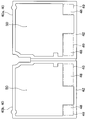
- FIG. 2 is a cross-sectional view taken along line II-II of FIG. It is a perspective view of an air-conditioning unit in a 1st embodiment of a state where adjustment parts are not provided. It is a front view of the adjustment component of 1st Embodiment. It is an enlarged view of the V section of FIG. It is a front view of adjustment parts which changed a part of adjustment parts of a 1st embodiment. It is a front view of the adjustment component of 2nd Embodiment.
- FIG. 7 shows a portion of an adjustment component in another embodiment.
- FIG. 7 shows a portion of an adjustment component in another embodiment.
- the air conditioning unit 10 is a vehicle air conditioning unit that constitutes a part of a vehicle air conditioner.
- the air conditioning unit 10 is mounted on the vehicle front side of the front seat in the vehicle compartment. More specifically, this air conditioning unit 10 is disposed inside the instrument panel.
- the air conditioning unit 10 blows the air that has passed through the heat exchanger toward the vehicle interior.
- the air conditioning unit 10 includes an air conditioning case 12, a blower (not shown), an evaporator 14, a heater core 16, and a PTC heater 18.
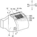
- the air conditioning case 12 constitutes an outer shell of the air conditioning unit 10. As shown in FIG. 1, the air conditioning case 12 is formed with a plurality of blowout openings 20, 22, 24. Each of the plurality of blowout openings 20, 22, 24 is an opening for blowing air from the inside of the air conditioning case 12 to the outside.
- the plurality of blowout openings 20, 22, 24 include a face opening 20, a defroster opening 22 and a foot opening 24.
- the face opening 20 is connected to a face outlet provided in an instrument panel (not shown) via a duct (not shown).
- the defroster opening 22 is connected to a defroster outlet provided in an instrument panel (not shown) via a duct (not shown).
- the face outlet includes a driver's seat center outlet, a driver's seat side outlet, a passenger seat center outlet and a passenger seat side outlet.
- the driver's seat center outlet and the driver's seat side outlet are provided on the driver's side of the instrument panel.
- the front passenger seat air outlet and the passenger side air outlet are provided on the passenger seat side of the instrument panel.
- the driver's seat center outlet and the passenger seat center outlet are provided on the center side of the instrument panel in the lateral direction of the vehicle.
- the driver's seat side outlet and the passenger seat side outlet are provided outside the instrument panel in the left-right direction of the vehicle.
- the face opening 20 includes a driver's seat center opening 201, a driver's seat side opening 202, a passenger's seat center opening 203, and a passenger's seat side opening 204.
- FIG. 3 shows the air conditioning unit 10 in a state in which the adjustment component 40 described later is not provided.
- the driver's seat center opening 201 continues to the driver's seat center outlet.
- the driver's seat side opening 202 is connected to the driver's seat side outlet.
- the front passenger seat center opening 203 is connected to the front passenger seat center outlet.
- the front passenger side opening 204 is connected to the front passenger side air outlet.
- the blower is provided inside the air conditioning case 12.
- the blower forms an air flow toward any of the plurality of blowout openings 20, 22, 24.
- the evaporator 14 is provided inside the air conditioning case 12.
- the evaporator 14 is a cooler that cools air directed to any of the plurality of blowout openings 20, 22, 24.
- the evaporator 14 is a heat exchanger for cooling, which evaporates the refrigerant and cools the air by heat exchange between the air and the refrigerant of the refrigeration cycle.
- the heater core 16 and the PTC heater 18 are provided inside the air conditioning case 12.
- the heater core 16 and the PTC heater 18 are heaters for heating air directed to any of the plurality of blowout openings 20, 22, 24.
- the heater core 16 is a heat exchanger for heating which heats air by heat exchange between the air and the engine coolant.
- the PTC heater 18 is an auxiliary heating device that heats the air that has passed through the heater core 16.
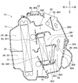
- an air passage 26 through which air flows toward any one of the plurality of blowout openings 20, 22, 24 is formed inside the air conditioning case 12.
- the air passage 26 includes an upper passage 28 located on the upper side inside the air conditioning case 12 and a lower passage 30 located on the lower side inside the air conditioning case 12.
- the upper passage 28 and the lower passage 30 are partitioned by upper and lower partition walls 32 provided in the air conditioning case 12.
- the upper passage 28 includes an upper warm air passage 281, an upper cold air passage 282 and an upper mixing passage 283 formed on the air flow downstream side of the evaporator 14.
- the upper warm air passage 281 guides the warm air generated by the air passing through the upper portion of the heater core 16 to the upper mixing passage 283.
- the upper cold air passage 282 guides the cold air generated by the air passing through the upper portion of the evaporator 14 to the upper mixing passage 283 by bypassing the upper portion of the heater core 16.
- the upper mixing passage 283 guides the mixed air of the warm air from the upper warm air passage 281 and the cold air from the upper cold air passage 282 to the face opening 20 and the defroster opening 22.
- the lower passage 30 includes a lower warm air passage 301, a lower cold air passage 302 and a lower mixing passage 303 formed on the air flow downstream side of the evaporator 14.
- the lower hot air passage 301 guides the warm air generated by the air passing through the lower portion of the heater core 16 to the lower mixing passage 303.
- a PTC heater 18 is disposed in the lower side hot air passage 301. The air that has passed through the lower portion of the heater core 16 is heated by the PTC heater 18.
- the lower cold air passage 302 guides the cold air generated by the air passing through the lower portion of the evaporator 14 to the lower mixing passage 303 by bypassing the lower portion of the heater core 16.
- the lower mixing passage 303 guides the mixed air of the warm air from the lower warm air passage 301 and the cold air from the lower cold air passage 302 to the foot opening 24 shown in FIG.
- the lower mixing passage 303 guides the mixed air of the warm air from the lower warm air passage 301 and the cold air from the lower cold air passage 302 to the upper mixing passage 283 via the communication port 305.
- the communication port 305 is formed in the upper and lower partition walls 32. The communication port 305 causes the upper mixing passage 283 and the lower mixing passage 303 to communicate with each other.
- the air conditioning unit 10 includes an air mix door 34 and a blowout mode door 36.
- the air mix door 34 is a temperature control door that adjusts the mixing ratio of cold air and warm air to adjust the temperature of the air conditioning air.
- the air mix door 34 includes an upper air mix door 341 and a lower air mix door 342.
- the upper air mix door 341 is disposed between the evaporator 14 and the heater core 16 in the upper passage 28.
- the lower air mixing door 342 is disposed between the evaporator 14 and the heater core 16 in the lower passage 30.
- the blowout mode door 36 selectively opens and closes the plurality of blowout openings 20, 22, 24.
- the blowout mode door 36 selectively opens and closes the plurality of blowout openings 20, 22, 24 to realize each blowout mode such as the face mode and the foot mode.
- the blowout mode door 36 includes a face door 361, a defroster door 362, and a foot door 363.
- the foot door 363 is integrated with a door 364 that opens and closes the communication port 305.
- the face door 361 opens the face opening 20.
- the defroster door 362 closes the defroster opening 22.
- the foot door 363 closes the communication passage 304 connected to the foot opening 24 and opens the communication port 305.
- the position of the air mix door 34 is set such that the temperature of the air blown out from the face outlet becomes a desired temperature.
- the warm air from each of the upper warm air passage 281 and the lower warm air passage 301 and the cold air from each of the upper cold air passage 282 and the lower cold air passage 302 are as shown by arrows in FIG. It flows toward the face opening 20 while being mixed in the upper mixing passage 283.
- the wind that has passed through each of the driver's seat center opening 201, the driver's seat side opening 202, the passenger seat center opening 203, and the passenger seat side opening 204 is the driver's seat center outlet, the driver's seat side outlet, and the passenger seat center.
- the air is blown out into the vehicle compartment from each of the air outlet and the passenger side air outlet.
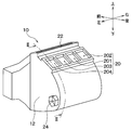
- the air conditioning unit 10 comprises two adjustment parts 40.
- the two adjustment components 40 include a first adjustment component 40 a provided in the driver's seat center opening 201 and a second adjustment component 40 b provided in the passenger seat center opening 203.
- the first adjustment component 40 a adjusts the air flow flowing out of the driver's seat center opening 201.
- the second adjustment component 40 b adjusts the air flow flowing out of the front passenger seat center opening 203.
- the first adjustment component 40a and the second adjustment component 40b are integrated.
- the first adjustment component 40 a is fixed to the driver's seat center opening 201.
- the second adjustment component 40 b is fixed to the front passenger seat center opening 203.
- the first adjustment component 40 a may be fixed to the driver's seat center opening 201 side of a duct connected to the driver's seat center opening 201.
- the second adjustment component 40 b may be fixed to the passenger seat center opening 203 side of the duct connected to the passenger seat center opening 203.
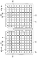
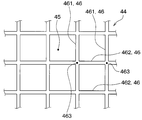
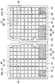
- each of the two adjustment parts 40 has a frame 42 and a grid 44.
- the frame 42 has a shape along the opening edge of the blowout opening where the adjustment component 40 is provided.
- the grid 44 is in the area enclosed by the frame 42.
- the grid 44 is a plurality of linear members 46 arranged to form a plurality of gaps 45.
- the plurality of linear members 46 are reticulated members that form the plurality of gaps 45.
- air can pass through the plurality of gaps 45. Therefore, the plurality of gaps 45 are a plurality of air passing portions through which air can pass.
- the plurality of linear members 46 is a partition that divides each of the plurality of air passing portions. In the present embodiment, the entire area surrounded by the frame 42 is the lattice area 47.
- the plurality of linear members 46 have a plurality of first linear members 461 and a plurality of second linear members 462.
- Each of the plurality of first linear members 461 is disposed spaced apart from one another.
- Each of the plurality of second linear members 462 is disposed spaced apart from one another.
- Each of the plurality of first linear members 461 intersects with each of the plurality of second linear members 462. For this reason, each shape of the plurality of gaps 45 is a square.
- each of the plurality of first linear members 461 and each of the plurality of second linear members 462 are coupled and integrated at an intersection portion 463 where the both intersect each other. As shown in FIG. 6, each of the plurality of first linear members 461 and each of the plurality of second linear members 462 may not be integrated at the intersection portion 463. That is, each of the plurality of first linear members 461 and each of the plurality of second linear members 462 may be knitted.
- the frame 42 and the lattice 44 are configured as an integrally molded product made of resin.
- An integrally molded article is a continuous molded article having no joint.
- the frame 42 and the grid 44 may not be made of resin.
- the air conditioning unit 10 of the present embodiment includes two adjustment components 40. Therefore, the air flow passing through each of the driver's seat center opening 201 and the passenger's seat center opening 203 can be rectified by the grid 44. As a result, the wind speed distribution of the wind blown out from each of the driver's seat center outlet and the passenger seat center outlet can be made to approach uniformly.
- the grid 44 can provide resistance to air flow passing through the driver's seat center opening 201 and the passenger's seat center opening 203, respectively. As a result, the wind volume can be reduced by reducing the volume of the wind blown out from each of the driver's seat center outlet and the passenger seat center outlet.
- the noise of the blowing air can be reduced as compared with the case where the two adjustment components 40 are not provided.
- the thicknesses of the plurality of linear members 46 may be changed, or the intervals between the adjacent linear members 46 may be changed. By making such a change, it is possible to adjust the pressure loss of the air flow passing through each of the driver's seat center opening 201 and the passenger's seat center opening 203 so as to obtain a desired noise reduction effect.
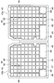
- this embodiment differs from the first embodiment in that the adjustment component 40 has a baffle plate 48.
- the other configuration of the air conditioning unit 10 is the same as that of the first embodiment.
- Each of the two adjustment parts 40 has a frame 42, a grid 44 and two baffles 48.
- the baffle plate 48 is a plate member that obstructs the air flow.
- the grid 44 and the two baffles 48 are disposed in the area surrounded by the frame 42.
- the two baffles 48 are arranged at a part of the periphery of the central part of the area surrounded by the frame 42. Therefore, the baffle plate 48 is biased in the area surrounded by the frame 42.
- the grid 44 is disposed in the area surrounded by the frame 42 except the two baffles 48.
- the frame 42, the lattice 44, and the two baffles 48 are formed of a resin integrally molded product. These may not be made of resin.
- the lattice area 47 in which the lattice 44 is disposed a plurality of gaps 45 are formed.
- the aperture ratio of the lattice region 47 is higher than the aperture ratio of the baffle plate region 49.
- the aperture ratio is the ratio of the gap formed by the member to the entire area in which the member is disposed. If the member does not form a gap, the aperture ratio is 0%. Therefore, the lattice area 47 is an area having lower resistance to air flow than the baffle area 49.
- the baffle area 49 is an area higher in resistance to air flow than the grid area 47.
- the grid 44 is a low resistance member that provides less resistance to air flow as compared to the baffle plate 48.
- the baffle plate 48 is a high resistance member that provides greater resistance to air flow as compared to the grid 44.
- the lattice area 47 corresponds to the first area through which air flows.
- the baffle plate area 49 corresponds to a second area having a greater resistance to air flow than the first area.
- the baffle plate 48 corresponds to a high resistance member that provides greater resistance to air flow than to the air flow in the first region.
- the grid 44 corresponds to a low resistance member that provides less resistance to air flow than to the air flow in the second region.
- the total area of the lattice area 47 including the lattice 44 and the plurality of gaps 45 is half or more of the total opening area of the blowout openings 201 and 203 provided with the adjustment component 40. is there.
- the lattice area 47 is a continuous area.
- the area of the portion of the baffle plate 48 that inhibits the air flow is larger than the average value of the areas of the plurality of gaps 45.
- the same effect as that of the first embodiment can be obtained by the grating 44. Furthermore, according to the present embodiment, the following effects can be obtained.
- the upper mixing passage 283 and the lower mixing passage 303 which are spaces for mixing cold air and warm air, are becoming smaller. Therefore, unlike the present embodiment, when the adjustment component 40 is not provided at the driver's seat center opening 201, the warm air and the cold air are not sufficiently mixed in the face mode, and the driver's seat center opening 201 Pass through. That is, in the driver's seat center opening 201, an area through which the warm air passes and an area through which the cold air passes exist. The warm air and the cold air that have passed through the driver's seat center opening 201 flow through the duct and are blown out from the driver's seat center outlet in this state.
- the adjustment component 40 is provided at the driver's seat center opening 201.
- the adjustment component 40 of the present embodiment has a baffle plate 48.
- the baffle plate region 49 has high resistance to air flow as compared with the region where the baffle plate 48 is not disposed (ie, the lattice region 47). Therefore, the wind flow passing through the driver's seat center opening 201 can be disturbed.
- the baffle plate 48 is disposed in the region on the warm wind side when the adjustment component 40 is not provided in the driver's seat center opening 201. For this reason, when warm air and cold air pass the driver's seat center opening 201 by the baffle plate 48, the warm air can be directed to the cold air side. Thereby, warm air and cold air can be mixed. Therefore, in the driver's seat center outlet, temperature variation in the outlet can be reduced.
- the adjustment component 40 is also provided in the front passenger seat center opening 203. For this reason, also in the front passenger seat center outlet, temperature variation in the outlet can be reduced.
- the upper mixing passage 283 and the lower mixing passage 303 are small and the adjustment component 40 is not provided in the driver's seat center opening 201 and the passenger's seat center opening 203.
- the temperature of the blowing air blown out from the blower outlet is higher in the driver's seat center blower outlet and the passenger seat center blower outlet than in the driver's seat side blower outlet and the passenger seat side blower outlet.
- the adjustment component 40 is provided in each of the driver's seat center opening 201 and the passenger's seat center opening 203 in the face opening 20.
- resistance to warm air is higher in the driver's seat center opening 201 and the passenger's seat center opening 203 than in the case where the adjustment component 40 is not provided. Therefore, the volume of warm air flowing through the driver's seat center opening 201 and the passenger's seat center opening 203 can be reduced, and the volume of warm air flowing through the driver's seat side opening 202 and the passenger seat side opening 204 can be increased.
- the mixing ratio of warm air and cold air passing through each of the driver's seat center opening 201, the driver's seat side opening 202, the assistant's seat center opening 203, and the assistant's seat side opening 204 can be made close.
- the temperatures of the air blown out from the driver's seat center outlet, the driver's seat side outlet, the passenger seat center outlet and the passenger seat side outlet can be made uniform.
- the baffle plate 48 adjusts the resistance to the air flow between the driver's seat center opening 201 and the passenger's seat center opening 203.
- the ease of warm air flow is adjusted in each of the openings 201, 202, 203, 204, and the mixing ratio of cold air and warm air is adjusted.
- the driver's seat center outlet, the passenger seat center outlet, the driver's seat side outlet, and the passenger seat side outlet temperature variations among the outlets can be reduced.
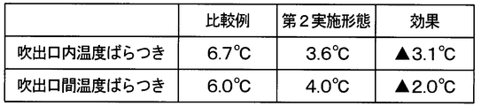
- FIG. 8 shows the test results conducted by the present inventor.
- FIG. 8 shows the measurement results of the temperature variation in the air outlet and the temperature variation between the air outlets in each of the air conditioning unit of the comparative example and the air conditioning unit 10 of this embodiment.
- the air conditioning unit of the comparative example is different from the air conditioning unit 10 of the present embodiment in that each of the two adjustment parts 40 does not have the two baffle plates 48.
- the other configurations of the air conditioning unit of the comparative example are the same as the air conditioning unit 10 of the present embodiment.
- the temperature variation in the outlet is the temperature variation in one face outlet, that is, the outlet at the driver's seat center outlet.
- the temperature variation between the outlets is the temperature variation between the four face outlets: the driver's seat center outlet, the passenger's seat center outlet, the driver's side outlet and the passenger's side outlet.
- the two adjustment parts 40 are parts separate from the air conditioning case 12. Therefore, by changing the number and position of the baffle plates 48 of the adjustment component 40, it is possible to reduce the temperature variation for each vehicle type on which the air conditioning unit 10 is mounted without changing the shape of the air conditioning case 12 Can.
- the two baffle plates 48 are disposed in the peripheral portion of the central portion of the area surrounded by the frame 42.
- the area surrounded by the frame 42 corresponds to the opening area of the blowout opening.
- the wind speed of the passing wind is high at the central portion of the opening area of the blowout opening.
- the wind speed of the passing wind is low.
- the baffle plate 48 is disposed in a region where the wind speed is low in the wind speed distribution of the wind passing through the blowout opening when the adjustment component 40 is not provided. Thereby, temperature variation can be made small, suppressing the fall of the amount of winds, and the aggravation of noise.
- positioning place and number of baffle plates 48 are not limited to this embodiment.
- the arrangement location and number of the baffles 48 can be arbitrarily changed.
- the baffle plate 48 may be disposed at the center of the area surrounded by the frame 42. By changing the area occupied by the baffle plate 48 with respect to the arrangement position of the baffle plate 48 and the area surrounded by the frame 42, the temperature distribution of the air blown out from the blowout port can be adjusted.
- the lattice 44 and the two baffle plates 48 are configured as an integrally molded product.
- the grid 44 and the two baffle plates 48 may be separately configured, and both may be joined.
- a plurality of openings 48 a are formed in each of the two baffle plates 48 in each of the two adjustment components 40.
- the other configuration of the air conditioning unit 10 is the same as that of the first embodiment.
- the plurality of openings 48 a may be formed in the baffle plate 48.
- the opening 48a may be one.
- the shapes of the two adjustment components 40 are different from those of the first embodiment.
- the other configuration of the air conditioning unit 10 is the same as that of the first embodiment.
- Each of the two adjustment parts 40 has a frame 42 and a grid 44a.
- the grating 44a is the same as the grating 44 of the first embodiment.
- the grid 44 a is disposed only in a part of the area surrounded by the frame 42.
- the area excluding the lattice area 47a is a hollow portion.
- the hollow portion 50 is formed in the area excluding the lattice area 47a in the area surrounded by the frame 42.
- the lattice area 47a is an area where the lattice 44a is disposed.
- the cavity 50 is an area where no member is disposed.
- the same effect as that of the first embodiment can be obtained by the grating 44.
- the aperture ratio of the cavity 50 is higher than the aperture ratio of the grating region 47a. Therefore, the cavity 50 is a region having lower resistance to the air flow than the lattice region 47a.
- the lattice area 47 a is an area where the resistance to air flow is higher than that of the cavity 50.
- the grid 44 a is a high resistance member that provides greater resistance to air flow as compared to the cavity 50. Therefore, also in this embodiment, the same effect as that of the second embodiment can be obtained.
- the hollow portion 50 corresponds to the first region through which air flows.
- the lattice area 47a corresponds to a second area having a higher resistance to air flow than the first area.
- the grid 44a corresponds to a high resistance member that provides greater resistance to air flow than to the air flow in the first region.
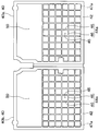
- the shapes of the two adjustment components 40 are different from those of the first embodiment.
- the other configuration of the air conditioning unit 10 is the same as that of the first embodiment.
- Each of the two adjustment parts 40 has a frame 42 and two baffles 48.
- the two baffles 48 are arranged only in a part of the area surrounded by the frame 42.
- the area excluding the baffle plate area 49 is a hollow portion.
- the hollow portion 50 is formed in the area excluding the baffle plate area 49 in the area surrounded by the frame 42.
- the cavity 50 is an area where no member is disposed.
- the aperture ratio of the hollow portion 50 is higher than the aperture ratio of the baffle plate region 49. Therefore, the hollow portion 50 is a region having lower resistance to air flow than the baffle plate region 49.
- the baffle plate region 49 is a region having a higher resistance to air flow than the hollow portion 50.
- the baffle plate 48 is a high resistance member that provides greater resistance to air flow as compared to the hollow portion 50. Therefore, also in this embodiment, the same effect as that of the second embodiment can be obtained.
- the hollow portion 50 corresponds to the first region through which air flows.
- the baffle plate area 49 corresponds to a second area having a greater resistance to air flow than the first area.
- the baffle plate 48 corresponds to a high resistance member that provides greater resistance to air flow than to the air flow in the first region.
- the shapes of the two adjustment components 40 are different from those in the first embodiment.
- the other configuration of the air conditioning unit 10 is the same as that of the first embodiment.
- Each of the two adjustment parts 40 has a frame 42, a first grating 44 and a second grating 52.
- the first grating 44 and the second grating 52 are arranged in the area surrounded by the frame 42.
- the first grating 44 is the same as the grating 44 of the second embodiment.
- the first grating region 47 in which the first grating 44 is disposed is the same as the grating region 47 of the second embodiment.
- the second grating 52 is, like the first grating 44, a plurality of linear members 46 arranged to form a plurality of gaps 45.
- the distance between the adjacent linear members 46 is narrower than that of the first grating 44.
- Adjacent linear members 46 are densely arranged. For this reason, in the second grating 52, each of the plurality of gaps 45 is smaller than the first grating 44.
- the same effect as that of the first embodiment can be obtained by the first grating 44 and the second grating 52.
- the aperture ratio of the first grating region 47 is higher than the aperture ratio of the second grating region 53 in which the second grating 52 is disposed.
- the first lattice area 47 is an area having a lower resistance to air flow than the second lattice area 53.
- the second lattice area 53 is an area having higher resistance to air flow than the first lattice area 47.
- the first grid 44 is a low resistance member that provides less resistance to air flow as compared to the second grid 52.
- the second grid 52 is a high resistance member that provides greater resistance to air flow as compared to the first grid 44. Therefore, also in this embodiment, the same effect as that of the second embodiment can be obtained.
- the first lattice area 47 corresponds to the first area through which air flows.
- the second lattice area 53 corresponds to a second area having a higher resistance to air flow than the first area.
- the second grid 52 corresponds to a high resistance member that provides greater resistance to air flow than to the air flow in the first region.
- the first grid 44 corresponds to a low resistance member that provides less resistance to air flow than to the air flow in the second region.
- each of the plurality of gaps 45 formed by the grating 44, the first grating 44, and the second grating 52 has a square shape.
- the shape of each of the plurality of gaps may be another shape other than a square.
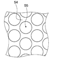
- each of the grid 44, the first grid 44, and the second grid 52 may be changed to a mesh member 54 forming a plurality of circular gaps 55.
- the plurality of circular gaps 55 are a plurality of air passing portions through which air can pass.
- the mesh member 54 is a partition that divides each of the plurality of air passing portions.
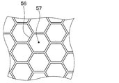
- each of the grid 44, the first grid 44, and the second grid 52 may be changed to a net-like member 56 forming a plurality of hexagonal gaps 57.
- the plurality of hexagonal gaps 57 are a plurality of air passage portions through which air can pass.
- the mesh member 56 is a partition that divides each of the plurality of air passing portions.
- the adjustment component 40 is provided only in two of the four openings 201, 202, 203, 204 of the face opening 20.
- the present invention is not limited to this case, and one or more of the four openings 201, 202, 203, 204 may be provided.
- the adjustment component 40 may be provided in all four openings 201, 202, 203, 204.
- the adjustment component 40 is provided in the face opening 20.
- the adjustment component 40 may be provided in another blowout opening. Thereby, the same effect as each of the above embodiments can be obtained.
- the air conditioning unit includes an air conditioning case, a cooler, a heater, and an adjustment component.
- the adjustment component is formed with a first region through which air flows and a second region where the resistance to air flow is greater than that of the first region.
- the second region is provided with a high resistance member that provides greater resistance to air flow than the first region.
- the resistance to air flow in the second region can be greater than the resistance to air flow in the first region.
- the low resistance member is provided in the first region to provide a smaller resistance to the air flow than the second region.
- the low resistance member can be provided in the first region.
- the low resistance member is a partition that divides each of the plurality of air passing portions through which air can pass.
- the high resistance member is a plate member having a portion that obstructs the air flow.
- the members described in the fourth aspect can be used as the low resistance member and the high resistance member.
- the partition can rectify the air flow passing through the blowout opening.
- the wind speed distribution of the blow-off wind which blows off from the blower outlet provided in the vehicle interior can be closely approached uniformly.
- the partition can provide resistance to the air flow passing through the blowout opening. As a result, it is possible to reduce the wind volume by reducing the volume of the blown air blown out from the blowout port into the vehicle compartment.
- the air conditioning unit includes the air conditioning case and the adjustment component.
- the adjustment component has a partition that separates each of the plurality of air passages through which air can pass.
Landscapes
- Engineering & Computer Science (AREA)
- Mechanical Engineering (AREA)
- Physics & Mathematics (AREA)
- Thermal Sciences (AREA)
- Air-Conditioning For Vehicles (AREA)
Abstract
La présente invention concerne une unité de climatisation (10) qui est pourvue : d'un boîtier de climatisation (12) dans lequel sont formées des ouvertures d'évacuation (201, 203) servant à évacuer l'air ; d'un refroidisseur disposé à l'intérieur du boîtier de climatisation et refroidissant l'air qui s'écoule vers les ouvertures d'évacuation ; d'un dispositif de chauffage disposé à l'intérieur du boîtier de climatisation et chauffant l'air s'écoulant vers les ouvertures d'évacuation ; et de parties de régulation (40) disposées au niveau des ouvertures d'évacuation et régulant les flux d'air qui passent dans les ouvertures d'évacuation. Les parties de régulation ont, formées en leur sein, des premières régions à travers lesquelles s'écoule de l'air et des secondes régions qui ont une résistance supérieure à l'écoulement d'air que celle des premières régions.
Priority Applications (3)
| Application Number | Priority Date | Filing Date | Title |
|---|---|---|---|
| DE112018004833.0T DE112018004833T5 (de) | 2017-08-30 | 2018-07-26 | Klimaanlageinheit |
| CN201880055721.9A CN111032385B (zh) | 2017-08-30 | 2018-07-26 | 空调单元 |
| US16/788,776 US11613155B2 (en) | 2017-08-30 | 2020-02-12 | Air-conditioning unit |
Applications Claiming Priority (2)
| Application Number | Priority Date | Filing Date | Title |
|---|---|---|---|
| JP2017165846A JP6915460B2 (ja) | 2017-08-30 | 2017-08-30 | 空調ユニット |
| JP2017-165846 | 2017-08-30 |
Related Child Applications (1)
| Application Number | Title | Priority Date | Filing Date |
|---|---|---|---|
| US16/788,776 Continuation US11613155B2 (en) | 2017-08-30 | 2020-02-12 | Air-conditioning unit |
Publications (1)
| Publication Number | Publication Date |
|---|---|
| WO2019044302A1 true WO2019044302A1 (fr) | 2019-03-07 |
Family
ID=65526301
Family Applications (1)
| Application Number | Title | Priority Date | Filing Date |
|---|---|---|---|
| PCT/JP2018/028141 WO2019044302A1 (fr) | 2017-08-30 | 2018-07-26 | Unité de climatisation |
Country Status (5)
| Country | Link |
|---|---|
| US (1) | US11613155B2 (fr) |
| JP (1) | JP6915460B2 (fr) |
| CN (1) | CN111032385B (fr) |
| DE (1) | DE112018004833T5 (fr) |
| WO (1) | WO2019044302A1 (fr) |
Cited By (2)
| Publication number | Priority date | Publication date | Assignee | Title |
|---|---|---|---|---|
| US20200406710A1 (en) * | 2019-06-28 | 2020-12-31 | Mahle International Gmbh | Hvac-module |
| WO2021209409A1 (fr) * | 2020-04-15 | 2021-10-21 | Valeo Systemes Thermiques | Dispositif de chauffage, ventilation et/ou climatisation pour vehicule automobile |
Citations (5)
| Publication number | Priority date | Publication date | Assignee | Title |
|---|---|---|---|---|
| JPS61145017U (fr) * | 1985-03-01 | 1986-09-06 | ||
| JPH05124432A (ja) * | 1991-11-06 | 1993-05-21 | Nippondenso Co Ltd | 自動車用空気調和装置 |
| KR20040065885A (ko) * | 2003-01-16 | 2004-07-23 | 현대모비스 주식회사 | 차량용 공기조화시스템의 에어 덕트 |
| KR20060072432A (ko) * | 2004-12-23 | 2006-06-28 | 한라공조주식회사 | 자동차용 공조장치 |
| JP2006188193A (ja) * | 2005-01-07 | 2006-07-20 | Calsonic Kansei Corp | 車両用空調装置 |
Family Cites Families (23)
| Publication number | Priority date | Publication date | Assignee | Title |
|---|---|---|---|---|
| IT232350Y1 (it) * | 1994-03-15 | 1999-12-17 | Foggini Progetti | Bocchetta di erogazione dell'aria di climatizzazione di autoveicoli con diffusore e concentratore di flusso selezionabili e singolarmente |
| JP3284058B2 (ja) * | 1996-08-30 | 2002-05-20 | 株式会社ケーヒン | 車両用暖房装置 |
| JP3870530B2 (ja) * | 1998-02-04 | 2007-01-17 | 株式会社デンソー | 車両用空調装置 |
| WO2001053073A1 (fr) | 2000-01-19 | 2001-07-26 | Chemfab Corporation | Membranes en materiau composite renforce non gondolant, dotees de faces opposees differentes, leurs procedes de production et leur utilisation dans diverses applications |
| US7927684B2 (en) | 2000-01-19 | 2011-04-19 | Saint-Gobain Performance Plastics Corporation | Low coefficient of friction polymer film |
| US7238102B2 (en) | 2003-02-18 | 2007-07-03 | Delphi Technologies, Inc. | Heating, ventilation, and air conditioning system having a film valve and film for controlling air flow |
| DE10121286A1 (de) * | 2001-04-30 | 2002-10-31 | Valeo Klimasysteme Gmbh | Luftführungsgehäuse |
| JP3879655B2 (ja) * | 2002-11-06 | 2007-02-14 | 株式会社デンソー | 車両空調用天井吹出装置 |
| DE10304548A1 (de) * | 2003-01-16 | 2004-07-29 | König & Hohmann und Otto Lübeck GmbH & Co. KG | Luftverteilungselement |
| DE10331398A1 (de) * | 2003-07-11 | 2005-01-27 | Volkswagen Ag | Luftausströmer mit einer Lochabdeckung |
| DE102004003196A1 (de) | 2004-01-22 | 2005-08-18 | Daimlerchrysler Ag | Belüftungseinrichtung für ein Kraftfahrzeug |
| DE102004057316A1 (de) * | 2004-11-27 | 2006-06-01 | Fischer Automotive Systems Gmbh | Lufteinleitvorrichtung |
| DE102006009577A1 (de) | 2006-02-28 | 2007-09-06 | Behr Gmbh & Co. Kg | Kraftfahrzeug-Belüftungssystem |
| CN101400960B (zh) * | 2006-03-10 | 2010-12-29 | 贝洱两合公司 | 用于汽车的热交换器 |
| DE102006026655A1 (de) * | 2006-06-08 | 2007-12-13 | Daimlerchrysler Ag | Kraftfahrzeug-Bauteil mit einem wölbstrukturierten Lochblech |
| FR2912085B1 (fr) * | 2007-02-05 | 2009-04-17 | Bourbon Automobile Soc Par Act | Buse de ventilation pour habitacle de vehicule automobile, notamment pour un appui tete de siege de vehicule automobile |
| DE102008021015A1 (de) | 2007-04-25 | 2008-10-30 | Behr Gmbh & Co. Kg | Vorrichtung zur Mischung von gasförmigen Medien und zum Absperren eines Querschnitts |
| JP2009040304A (ja) * | 2007-08-10 | 2009-02-26 | Denso Corp | 車両用空調装置 |
| KR101481697B1 (ko) * | 2008-09-29 | 2015-01-12 | 한라비스테온공조 주식회사 | 차량용 공조장치 |
| DE102011113446A1 (de) * | 2011-09-14 | 2013-03-14 | Valeo Klimasysteme Gmbh | Fahrzeugklimaanlage |
| WO2013185012A1 (fr) * | 2012-06-08 | 2013-12-12 | Johnson Controls Technology Company | Ensemble d'aération à matériau flexible |
| KR101595244B1 (ko) * | 2012-10-30 | 2016-02-18 | 한온시스템 주식회사 | 차량용 공조장치 |
| JP2017165846A (ja) | 2016-03-15 | 2017-09-21 | アーゼッド・エレクトロニック・マテリアルズ(ルクセンブルグ)ソシエテ・ア・レスポンサビリテ・リミテ | 微細パターン形成用組成物およびそれを用いた微細パターン形成方法 |
-
2017
- 2017-08-30 JP JP2017165846A patent/JP6915460B2/ja active Active
-
2018
- 2018-07-26 DE DE112018004833.0T patent/DE112018004833T5/de active Pending
- 2018-07-26 CN CN201880055721.9A patent/CN111032385B/zh active Active
- 2018-07-26 WO PCT/JP2018/028141 patent/WO2019044302A1/fr active Application Filing
-
2020
- 2020-02-12 US US16/788,776 patent/US11613155B2/en active Active
Patent Citations (5)
| Publication number | Priority date | Publication date | Assignee | Title |
|---|---|---|---|---|
| JPS61145017U (fr) * | 1985-03-01 | 1986-09-06 | ||
| JPH05124432A (ja) * | 1991-11-06 | 1993-05-21 | Nippondenso Co Ltd | 自動車用空気調和装置 |
| KR20040065885A (ko) * | 2003-01-16 | 2004-07-23 | 현대모비스 주식회사 | 차량용 공기조화시스템의 에어 덕트 |
| KR20060072432A (ko) * | 2004-12-23 | 2006-06-28 | 한라공조주식회사 | 자동차용 공조장치 |
| JP2006188193A (ja) * | 2005-01-07 | 2006-07-20 | Calsonic Kansei Corp | 車両用空調装置 |
Cited By (5)
| Publication number | Priority date | Publication date | Assignee | Title |
|---|---|---|---|---|
| US20200406710A1 (en) * | 2019-06-28 | 2020-12-31 | Mahle International Gmbh | Hvac-module |
| US11685231B2 (en) * | 2019-06-28 | 2023-06-27 | Mahle International Gmbh | HVAC-module |
| WO2021209409A1 (fr) * | 2020-04-15 | 2021-10-21 | Valeo Systemes Thermiques | Dispositif de chauffage, ventilation et/ou climatisation pour vehicule automobile |
| FR3109333A1 (fr) * | 2020-04-15 | 2021-10-22 | Valeo Systemes Thermiques | Dispositif de chauffage, ventilation et/ou climatisation pour véhicule automobile |
| CN115380155A (zh) * | 2020-04-15 | 2022-11-22 | 法雷奥热系统公司 | 用于机动车辆的供暖、通风和/或空调装置 |
Also Published As
| Publication number | Publication date |
|---|---|
| DE112018004833T5 (de) | 2020-07-09 |
| JP6915460B2 (ja) | 2021-08-04 |
| JP2019043226A (ja) | 2019-03-22 |
| CN111032385B (zh) | 2023-02-28 |
| US20200180389A1 (en) | 2020-06-11 |
| US11613155B2 (en) | 2023-03-28 |
| CN111032385A (zh) | 2020-04-17 |
Similar Documents
| Publication | Publication Date | Title |
|---|---|---|
| JP4638111B2 (ja) | 自動車用空調装置 | |
| US8460073B2 (en) | Air conditioner for vehicle | |
| US11254187B2 (en) | Vehicular air conditioner | |
| JP2018047711A (ja) | 車両用空調装置 | |
| US11554630B2 (en) | Vehicular air conditioner having heating heat exchanger disposed downstream of blower fan | |
| KR102474617B1 (ko) | 자동차용 트리플 존 공기조화장치 | |
| US8661844B2 (en) | Door for controlling temperature and airflow distribution of a heating, ventilation, and air conditioning system in a vehicle | |
| WO2016088361A1 (fr) | Unité de climatisation de véhicule | |
| WO2019044302A1 (fr) | Unité de climatisation | |
| CN107662474B (zh) | 用于对车辆内部空间进行多区空气调节的方法和空调设备 | |
| WO2015012286A1 (fr) | Unité de climatisation de véhicule | |
| KR102056123B1 (ko) | 자동차 공조 시스템용 공기 분배 어셈블리 | |
| US9423147B2 (en) | Mixer for mixing air flows | |
| JP6795896B2 (ja) | 車両用空調装置 | |
| JP2011025810A (ja) | 車両用空調装置 | |
| JP2005306166A (ja) | 車両用空調装置 | |
| JP5532545B2 (ja) | 空調装置 | |
| US11117446B2 (en) | Blower device | |
| KR20100006970A (ko) | 차량용 공조시스템 | |
| US20220305875A1 (en) | Control device, and associated heating and/or ventilation and/or air conditioning installation, motor vehicle and temperature management method | |
| JP5928866B2 (ja) | 空調用ダクト | |
| KR101596787B1 (ko) | 차량용 공조장치 | |
| JP2009149126A (ja) | 車両用空調装置 | |
| WO2016103639A1 (fr) | Dispositif de climatisation de véhicule | |
| JP2005231406A (ja) | 車両用空調ユニット |
Legal Events
| Date | Code | Title | Description |
|---|---|---|---|
| 121 | Ep: the epo has been informed by wipo that ep was designated in this application |
Ref document number: 18852548 Country of ref document: EP Kind code of ref document: A1 |
|
| 122 | Ep: pct application non-entry in european phase |
Ref document number: 18852548 Country of ref document: EP Kind code of ref document: A1 |