WO2019044153A1 - グロープラグ用のセラミックヒータ及びグロープラグ用のセラミックヒータの製造方法 - Google Patents
グロープラグ用のセラミックヒータ及びグロープラグ用のセラミックヒータの製造方法 Download PDFInfo
- Publication number
- WO2019044153A1 WO2019044153A1 PCT/JP2018/024751 JP2018024751W WO2019044153A1 WO 2019044153 A1 WO2019044153 A1 WO 2019044153A1 JP 2018024751 W JP2018024751 W JP 2018024751W WO 2019044153 A1 WO2019044153 A1 WO 2019044153A1
- Authority
- WO
- WIPO (PCT)
- Prior art keywords
- ceramic heater
- glow plug
- insulating member
- conductive member
- silicon nitride
- Prior art date
- Legal status (The legal status is an assumption and is not a legal conclusion. Google has not performed a legal analysis and makes no representation as to the accuracy of the status listed.)
- Ceased
Links
Images



Classifications
-
- F—MECHANICAL ENGINEERING; LIGHTING; HEATING; WEAPONS; BLASTING
- F23—COMBUSTION APPARATUS; COMBUSTION PROCESSES
- F23Q—IGNITION; EXTINGUISHING-DEVICES
- F23Q7/00—Incandescent ignition; Igniters using electrically-produced heat, e.g. lighters for cigarettes; Electrically-heated glowing plugs
-
- H—ELECTRICITY
- H05—ELECTRIC TECHNIQUES NOT OTHERWISE PROVIDED FOR
- H05B—ELECTRIC HEATING; ELECTRIC LIGHT SOURCES NOT OTHERWISE PROVIDED FOR; CIRCUIT ARRANGEMENTS FOR ELECTRIC LIGHT SOURCES, IN GENERAL
- H05B3/00—Ohmic-resistance heating
- H05B3/10—Heating elements characterised by the composition or nature of the materials or by the arrangement of the conductor
-
- H—ELECTRICITY
- H05—ELECTRIC TECHNIQUES NOT OTHERWISE PROVIDED FOR
- H05B—ELECTRIC HEATING; ELECTRIC LIGHT SOURCES NOT OTHERWISE PROVIDED FOR; CIRCUIT ARRANGEMENTS FOR ELECTRIC LIGHT SOURCES, IN GENERAL
- H05B3/00—Ohmic-resistance heating
- H05B3/10—Heating elements characterised by the composition or nature of the materials or by the arrangement of the conductor
- H05B3/12—Heating elements characterised by the composition or nature of the materials or by the arrangement of the conductor characterised by the composition or nature of the conductive material
-
- H—ELECTRICITY
- H05—ELECTRIC TECHNIQUES NOT OTHERWISE PROVIDED FOR
- H05B—ELECTRIC HEATING; ELECTRIC LIGHT SOURCES NOT OTHERWISE PROVIDED FOR; CIRCUIT ARRANGEMENTS FOR ELECTRIC LIGHT SOURCES, IN GENERAL
- H05B3/00—Ohmic-resistance heating
- H05B3/10—Heating elements characterised by the composition or nature of the materials or by the arrangement of the conductor
- H05B3/12—Heating elements characterised by the composition or nature of the materials or by the arrangement of the conductor characterised by the composition or nature of the conductive material
- H05B3/14—Heating elements characterised by the composition or nature of the materials or by the arrangement of the conductor characterised by the composition or nature of the conductive material the material being non-metallic
-
- H—ELECTRICITY
- H05—ELECTRIC TECHNIQUES NOT OTHERWISE PROVIDED FOR
- H05B—ELECTRIC HEATING; ELECTRIC LIGHT SOURCES NOT OTHERWISE PROVIDED FOR; CIRCUIT ARRANGEMENTS FOR ELECTRIC LIGHT SOURCES, IN GENERAL
- H05B3/00—Ohmic-resistance heating
- H05B3/10—Heating elements characterised by the composition or nature of the materials or by the arrangement of the conductor
- H05B3/18—Heating elements characterised by the composition or nature of the materials or by the arrangement of the conductor the conductor being embedded in an insulating material
-
- H—ELECTRICITY
- H05—ELECTRIC TECHNIQUES NOT OTHERWISE PROVIDED FOR
- H05B—ELECTRIC HEATING; ELECTRIC LIGHT SOURCES NOT OTHERWISE PROVIDED FOR; CIRCUIT ARRANGEMENTS FOR ELECTRIC LIGHT SOURCES, IN GENERAL
- H05B3/00—Ohmic-resistance heating
- H05B3/40—Heating elements having the shape of rods or tubes
- H05B3/42—Heating elements having the shape of rods or tubes non-flexible
- H05B3/48—Heating elements having the shape of rods or tubes non-flexible heating conductor embedded in insulating material
Definitions
- the present invention relates to a ceramic heater for a glow plug and a method for manufacturing a ceramic heater for a glow plug, which are used as start aids for an internal combustion engine such as a diesel engine.
- a ceramic heater in which a heating resistor made of an inorganic conductive material is embedded in a silicon nitride sintered body is known as a ceramic heater for ignition of various combustion devices (see, for example, Patent Document 1).
- a ceramic heater made of a silicon nitride sintered body has high strength and is excellent in heat resistance, thermal shock resistance and oxidation resistance, and may be used in heat engine parts such as automotive parts. (For example, refer patent document 2).
- a ceramic heater using a silicon nitride sintered body may be used for a glow plug as a start assisting device for an internal combustion engine such as a diesel engine.
- an internal combustion engine such as a diesel engine.
- many vehicles are equipped with systems such as low pressure and high pressure EGR for recirculating exhaust gas, and an intake intercooler. With these systems, for example, moisture contained in the exhaust gas may intrude into the combustion chamber of the internal combustion engine.
- the surface temperature of the ceramic heater used as an internal combustion engine start auxiliary device may be raised to about 1300 ° C. at the start of the internal combustion engine.
- the surface of the ceramic heater is quenched.
- a large temperature difference occurs between the surface of the ceramic heater and the inside thereof, and a large thermal stress is generated near the surface of the ceramic heater due to the difference in thermal expansion. Due to this thermal stress (tensile stress on the heater surface), the ceramic heater may be broken, and the ceramic heater member may fall off in the combustion chamber.
- this invention is made in view of the said subject, and it aims at providing the ceramic heater provided with the high thermal shock resistance for glow plugs.
- the present invention is a ceramic heater for a glow plug inserted into a combustion chamber of an internal combustion engine, comprising a conductive member and an insulating member covering the conductive member.
- the insulating member characterized in that silicon nitride (Si 3 N 4) is a parent phase, containing the nanocomposite dispersed nano-sized silicon carbide (SiC) in nitride silicon (Si 3 N 4) I assume.
- the present invention is further a ceramic heater for a glow plug inserted into a combustion chamber of an internal combustion engine, comprising: a conductive member; and an insulating member covering the conductive member.
- the insulating member contains silicon nitride (Si 3 N 4 ) and nanosized titanium oxide (TiO 2 ).
- the conductive member is formed of a mixture containing tungsten carbide (WC), the silicon nitride, and a rare earth element compound.
- WC tungsten carbide
- the silicon nitride silicon nitride
- rare earth element compound tungsten carbide
- the said electroconductive member contains at least one of each element of titanium (Ti), vanadium (V), chromium (Cr), manganese (Mn), and iron (Fe).
- content of the said element is 0.5 mol% or less.
- the insulating member preferably contains at least one of aluminum (Al), calcium (Ca) and magnesium (Mg) as a glass composition.
- nano-sized molybdenum disilicide MoSi 2
- MoSi 2 nano-sized molybdenum disilicide
- the conductive member has a heating element and a lead connected to the heating element, and the lead is made of titanium (Ti), vanadium (V), chromium (Cr), manganese (Mn), iron It is preferable to contain at least one oxide or nitride of the elements of (Fe).
- the present invention is further a method of manufacturing a ceramic heater for a glow plug inserted into a combustion chamber of an internal combustion engine, the method comprising the steps of: using a conductive ceramic powder and a resin material.
- the present invention is further a method of manufacturing a ceramic heater for a glow plug inserted into a combustion chamber of an internal combustion engine, the method comprising the steps of: using a conductive ceramic powder and a resin material.
- the compound for the conductive member preferably contains tungsten carbide (WC), the silicon nitride (Si 3 N 4 ), and a rare earth element compound.
- a rare earth element compound as a sintering aid into the compound for the insulating member.
- the hot press sintering in an inert gas or reducing gas having a gas pressure of 0.1 to 0.3 MPa.
- the present invention is further a glow plug, in which the above-mentioned ceramic heater, a cylinder supporting the proximal end of the ceramic heater, and the state in which the tip of the ceramic heater is exposed And a housing for supporting the cylindrical body.
- the mechanical characteristics are excellent, and the thermal shock resistance of the ceramic heater is improved.
- FIG. 1 is a cross-sectional view for explaining the configuration of the glow plug.
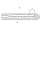
- FIG. 2 is a view showing a glow plug ceramic heater.
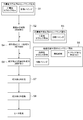
- FIG. 3 is a view for explaining the manufacturing process of the ceramic heater according to the first embodiment.
- the glow plug 1 includes a ceramic heater element (ceramic heater) 10, a cylindrical body 20, and a housing 30.
- the ceramic heater element 10 is a portion where the tip is inserted into the combustion chamber of the internal combustion engine, and has the conductive member 11 and the insulating member 16 covering the conductive member 11.
- the conductive member 11 is a member heated by energization in the glow plug 1 and has a heating element 12 formed in a U-shape and leads 14 formed and connected to each end of the heating element 12.
- the heating element 12 is a heating resistor having high resistance to the lead 14.
- the heat generating body 12 is formed of, for example, a material containing carbides, nitrides, silicides, and the like as main components including tungsten (W), molybdenum (Mo), titanium (Ti), and the like.
- the heating element 12 preferably contains tungsten carbide (WC) having inorganic heat conductivity in that it has high heat resistance and low specific resistance.
- the heat generating body 12 preferably contains silicon nitride (Si 3 N 4 ) in addition to the above main components, and the content of silicon nitride (Si 3 N 4 ) is preferably 20% by mass or more.
- the thermal expansion coefficient of the conductor component to be the heat generating body 12 is larger than that of silicon nitride (Si 3 N 4 ) in the insulating member 16 containing silicon nitride ceramics, a tensile stress is usually applied. It is in.
- silicon nitride (Si 3 N 4 ) into the heat generating body 12 the thermal expansion coefficient is made close to the thermal expansion coefficient of the insulating member 16 to raise or lower the temperature of the ceramic heater element 10. The stress due to the difference in the coefficient of thermal expansion can be relieved.
- the content of silicon nitride (Si 3 N 4 ) contained in the heat generating body 12 is 40 mass% or less, the resistance value of the heat generating body 12 can be made relatively small and stable. Therefore, the content of silicon nitride (Si 3 N 4 ) contained in the heating element 12 is preferably 20 to 40% by mass. More preferably, the content of silicon nitride (Si 3 N 4 ) is 25 to 35% by mass. As a similar additive to the heating element 12, 4 to 12% by mass of boron nitride (BN) may be added instead of silicon nitride (Si 3 N 4 ).
- BN boron nitride
- the heat generating body 12 preferably has, for example, a rectangular cross-sectional shape, one side (thickness) of 0.5 to 1.5 mm, and the other side (width) of 0.3 to 1.3 mm. Within this range, the heat generated from the heating element 12 is efficiently and uniformly transmitted to the insulating member 16, and the surface temperature distribution becomes uniform.
- elements 4, 5 6, 7 and 8 of Group 4 of the periodic table of the element periodic table may be contained.
- the content of elements of titanium (Ti), vanadium (V), chromium (Cr), manganese (Mn), and iron (Fe) in the heating element 12 is preferably 0.5 mol% or less.
- the heat generating body 12 is preferably a mixture containing a rare earth element compound such as chromium oxide (Cr 2 O 3 ) of several tens of ppm, for example, and it is a sintered body formed by sintering as described later. is there.
- the positive electrode 121 and the negative electrode 122 are provided at both ends of the heat generating body 12 via the leads 14.
- the negative electrode 122 is taken out to the outer peripheral surface of the insulating member 16, and the negative electrode side metallized portion 123 is formed on the outer peripheral surface of the insulating member 16 containing the negative electrode 122.
- the negative electrode side metallized portion 123 is joined to the inner surface of the cylindrical body 20 by brazing or the like, and the negative side electrode 122 is electrically connected to the cylindrical body 20 formed of a conductive metal material.
- the positive electrode 121 is taken out from the outer surface of the insulating member 16 on the base end side opposite to the front end side of the glow plug 1 or the ceramic heater element 10 in which the heating element 12 is embedded.
- a metallized portion 124 is formed on the rear end surface of the insulating member 16 including the positive electrode 121.
- the metallized portion 124 is electrically connected to the other lead 13 via a metal sleeve 13a by brazing or the like
- the lead 14 is connected to the heating element 12 at one end, and is exposed from the insulating member 16 at the other end.
- the leads 14 have low resistance to the heating element 12.
- the leads 14 are respectively connected to both ends of the heating element 12 extending in a U-shape.
- the lead 14 preferably contains tungsten carbide (WC), which is an inorganic conductor, as a main component, to which silicon nitride (Si 3 N 4 ) is preferably added so as to have a content of 15% by mass or more.
- WC tungsten carbide
- the thermal expansion coefficient of the lead 14 can be made close to the thermal expansion coefficient of silicon nitride (Si 3 N 4 ) contained in the insulating member 16 as the content rate of silicon nitride (Si 3 N 4 ) increases.
- the content of silicon nitride is 40% by mass or less, the resistance value of the lead 14 is reduced and stabilized. Therefore, the content of silicon nitride (Si 3 N 4 ) is preferably 15 to 40% by mass. More preferably, the content of silicon nitride (Si 3 N 4 ) is 20 to 35% by mass.
- an element (titanium (Ti), vanadium (V), chromium (Cr), manganese (Mn), iron (Fe), group 4, 5, 6, 7, 8 of the 4th period of the element periodic table) )) May contain at least one oxide and / or nitride.
- the content of the elements of titanium (Ti), vanadium (V), chromium (Cr), manganese (Mn), and iron (Fe) in the lead 14 is preferably 0.5 mol% or less.
- the lead 14 is preferably a mixture containing a rare earth element compound such as chromium oxide (Cr 2 O 3 ) of about several tens of PPM, for example, and is a sintered body formed by sintering as described later.
- the lead 14 is formed of the same material as the heating element 12, but, for example, includes more forming material than the heating element 12 or makes the cross-sectional area larger than that of the heating element 12 or the like.
- the resistance per unit length is low.
- the insulating member 16 is, for example, a sintered body formed by sintering into a rod shape.
- the insulating member 16 covers the conductive member 11, and more specifically, the insulating member 16 covers the heating element 12 and the lead 14. In other words, the heating element 12 and the leads 14 are embedded in the insulating member 16.
- the length of the insulating member 16 is, for example, 20 to 50 mm, and the diameter of the insulating member 16 is, for example, 3 to 5 mm.
- the insulating member 16 is preferably made of ceramic, which makes it possible to provide the ceramic heater element 10 with high reliability at the time of rapid temperature rise.
- ceramics having electrical insulating properties such as oxide ceramics, nitride ceramics, carbide ceramics and the like can be mentioned.
- the insulating member 16 is formed of nitride ceramic. More specifically, the insulating member 16 is formed of a silicon nitride ceramic containing silicon nitride (Si 3 N 4 ) as a starting material.
- ⁇ -type silicon nitride ( ⁇ -Si 3 N 4 ) is used as a starting material, but the insulating member 16 which is a sintered body after the firing process is in silicon nitride (Si 3 N 4 ) It is preferable to contain ⁇ -type silicon nitride ( ⁇ -Si 3 N 4 ). For example, it is preferable to contain silicon nitride (Si 3 N 4) 50 ⁇ 90 wt% or more beta-silicon nitride in ( ⁇ -Si 3 N 4) .
- silicon nitride (Si 3 N 4 ) which is the main component, is excellent in terms of high strength, high toughness, high insulation, and heat resistance.
- This silicon nitride ceramic is, for example, 3 to 12% by mass of yttrium (Y), ytterbium (Yb), erbium (Er), etc. as a sintering aid with respect to silicon nitride (Si 3 N 4 ) as the main component.
- the rare earth element oxide is mixed with 0.5 to 3% by mass of aluminum oxide (Al 2 O 3 ), and further to 1.5 to 5% by mass of silicon oxide (SiO 2 ).
- a nanocomposite comprising silicon nitride (Si 3 N 4 ) contained in the insulating member 16 with the silicon nitride (Si 3 N 4 ) as a matrix and nano-sized silicon carbide (SiC) dispersed in the matrix.
- SiC silicon carbide
- the insulating member 16 In the case of using one made of silicon nitride ceramics as the insulating member 16, it is preferable to mixing molybdenum disilicide (MoSi 2) or the like of the nanosized dispersion.
- MoSi 2 molybdenum disilicide
- the coefficient of thermal expansion of the mother silicon nitride ceramic can be made close to the coefficient of thermal expansion of the heat generating body 12, and the durability of the ceramic heater element 10 can be improved.
- the glass phase exists in the sintered compact grain boundary in the insulating member 16, and the insulating member 16 has, for example, aluminum (Al), calcium (Ca), magnesium (Mg), or the like as a glass composition. Contains oxides.
- Aluminum (Al) is a glass phase forming component
- calcium (Ca) and magnesium (Mg) are glass forming components.
- the housing 30 is a fixture to a cylinder head of an engine (not shown), and accommodates the ceramic heater element 10 together with the cylindrical body 20 as shown in FIG.
- the housing 30 is formed of a thermally conductive metal material having excellent heat dissipation.
- the housing 30 is formed, for example, in a cylindrical shape, and the ceramic heater element 10 is partially supported on the base end side by the cylindrical body 20, and the cylindrical body 20 is disposed inside the housing 30. In this state, the tip end of the ceramic heater element 10 protrudes outward from the tip of the housing 30.
- the ceramic heater element 10 may be fixed to the inner peripheral surface of the housing 30 by brazing.
- the tip of the ceramic heater element 10 protruding from the housing 30, specifically the tip of the ceramic heater element 10, is inserted into the combustion chamber of the internal combustion engine.
- the ceramic heater element 10 can be manufactured, for example, by an injection molding method using a mold of the shape of the heating element 12 of the conductive member 11, the lead 14, and the insulating member 16 and hot press molding.
- a compound for a low conductivity member is prepared (step S1). Specifically, in step S1, the conductive ceramic powder and the thermoplastic resin binder (resin material) are mixed to prepare a compound for the low conductive member for the heat generating body 12.
- the compound for the low conductivity member for the heating element 12 is formulated to have high resistance.
- At least one of vanadium (V), chromium (Cr), manganese (Mn), iron (Fe), and a resin binder are prepared.
- a rare earth element compound may be mixed in the compound for the low conductive member.
- the compound for the low conductive member thus prepared is injected into a mold to form a molded body A to be the heating element 12 shaped as shown in FIG. 1 (step S
- the conductive ceramic powder and the thermoplastic resin binder (resin material) are mixed to prepare a compound for the highly conductive member for the lead 14.
- the compound for the highly conductive member for the lead 14 is compounded to have low resistance to the heating element 12 (step S3).
- at least one oxide and / or nitride of titanium (Ti), vanadium (V), chromium (Cr), manganese (Mn), iron (Fe) is added It is also good.
- the compound for the highly conductive member may be mixed with a rare earth element compound.
- the compound for the highly conductive member for the lead 14 is different in content of various materials contained in the compound for the low conductive member for the heating element 12.
- a molded body B in which the leads 14 are integrally molded is molded on the molded body A molded in step S2 (step S4).
- the compound for the highly conductive member prepared in step S3 is injected into the mold in which the molded body A is held, and the lead 14 shaped as shown in FIG. 1 is obtained.
- a molded body B is manufactured by integrally molding the molded body A.
- the compact B corresponds to the conductive member 11 before sintering.
- a compound for the insulating member to be the insulating member 16 is prepared (step S5).
- the compound for the insulating member is a resin binder (resin material) and a sintering aid in a silicon nitride (Si 3 N 4 ) powder in which ⁇ -type silicon nitride ( ⁇ -Si 3 N 4 ) is at least 90% by mass.
- oxides of rare earth elements such as yttrium (Y), ytterbium (Yb), erbium (Er) (eg, Y 2 O 3 , Yb 2 O 3 , Er 2 O 3 etc.), and aluminum (Al)
- Y yttrium
- Yb ytterbium
- Er erbium
- Al aluminum
- Mg magnesium
- Ca calcium
- SiC silicon carbide
- a part of the mold is exchanged for molding of the insulating member 16, and then a compound for the insulating member to be the insulating member 16 in the mold Are injection-molded to form a molded body to be the insulating member 16 so as to cover the molded body B, thereby producing a molded body C in which the heating element 12 and the leads 14 are embedded (step S6).
- step S6 the green body C obtained in step S6 is degreased at a low temperature of less than 500 ° C. to decompose the binder in the green body C (step S7).
- step S8 the compact C is fired. Specifically, after the molded body C is placed in a cylindrical carbon mold, it is hot pressed at a temperature of 1600 ° C. to 1800 ° C. and a pressure of 0.1 to 30 MPa in an inert gas or reducing gas atmosphere. Sintering is performed to form a compact C. Thereafter, the sintered body (sintered compact C) is ground to complete the ceramic heater element 10.
- step S1 may be prepared in advance or may be prepared in parallel.
- step S5 instead of nanosized silicon carbide (SiC), a precursor (silicon carbide precursor) of silicon carbide (SiC) may be highly dispersed and mixed.
- precursors of silicon carbide (SiC) include polycarbosilane, polycarbosilazane, and polo-organosilazane.
- the insulating member 16 is mainly composed of silicon nitride (Si 3 N 4 ) having high strength, high toughness, high insulation, and high heat resistance, and the main component is nano Since it contains a nanocomposite in which silicon carbide (SiC) of a size is mixed, for example, fracture strength, fracture toughness, creep / fatigue fracture strength, thermal shock resistance, thermal conductivity, corrosion resistance, maximum use temperature etc. It can be enhanced.
- SiC silicon carbide
- the water collides with the surface of the insulating member 16 of the ceramic heater element 10 in the high temperature state in the combustion chamber of the internal combustion engine, and a difference in thermal expansion occurs between the surface of the insulating member 16 and the inside thereof. Even if the high temperature strength, the thermal conductivity and the like are improved, the thermal expansion difference can be suppressed to be a slight difference. Thus, breakage of the ceramic heater element 10 can be suppressed.
- the insulating member 16 contains silicon carbide (SiC), molybdenum disilicide (MoSi 2 ), etc.
- silicon oxide (SiO 2 ) is formed on the surface of silicon carbide (SiC) or molybdenum disilicide (MoSi 2 ). ) Is produced as a protective film.
- the composition of the insulating member 16 of the glow plug 1 according to the second embodiment is different from the composition of the insulating member 16 of the glow plug 1 according to the first embodiment.
- the insulating member 16 is formed of nitride ceramic. More specifically, the insulating member 16 is formed of a silicon nitride ceramic containing silicon nitride (Si 3 N 4 ) as a starting material. The insulating member 16 contains silicon nitride (Si 3 N 4 ) and a nanosized metal oxide, specifically titanium oxide (TiO 2 ).
- the ceramic heater element 10 Next, a method of manufacturing the ceramic heater element 10 will be described with reference to FIG. 4.
- the steps S11, S21, S31, S41, S61, S71, and S81 are the first embodiment S1 to S4 and S6 to S8. Since it is the same as, the explanation is omitted.
- the compound for the insulating member prepared in step S51 is a powder of silicon nitride (Si 3 N 4 ) containing 90% by mass or more of ⁇ -type silicon nitride ( ⁇ -Si 3 N 4 ).
- Resin binder as a sintering aid, for example, oxides of rare earth elements such as yttrium (Y), ytterbium (Yb), erbium (Er) (eg, Y 2 O 3 , Yb 2 O 3 , Er) 2 O 3 etc., and aluminum (Al), magnesium (Mg) or calcium (Ca) or oxides thereof (eg, Al 2 O 3 , MgO, CaO) and the like.
- nano-sized titanium oxide (TiO 2 ) powder is added (doped) to the compound for the insulating member.
- titanium oxide (TiO 2 ) is highly dispersed and mixed into silicon nitride (Si 3 N 4 ) using a dry particle composite apparatus “Novirta” manufactured by Hosokawa Micron Corporation.
- the compounding of the compound for the insulating member for the insulating member 16 of the glow plug 1 according to the third embodiment is the compounding of the compound for the insulating member used in the second embodiment. It is different from
- the insulating member 16 is formed of nitride ceramic. More specifically, the insulating member 16 is formed of a silicon nitride ceramic containing silicon nitride (Si 3 N 4 ) as a starting material. The insulating member 16 contains silicon nitride (Si 3 N 4 ) and metal oxide dispersed in nanosize, specifically titanium oxide (TiO 2 ).
- the compound for the insulating member prepared in step S52 is a powder of silicon nitride (Si 3 N 4 ) containing 90% by mass or more of ⁇ -type silicon nitride ( ⁇ -Si 3 N 4 ).
- Resin binder as a sintering aid, for example, oxides of rare earth elements such as yttrium (Y), ytterbium (Yb), erbium (Er) (eg, Y 2 O 3 , Yb 2 O 3 , Er) 2 O 3 etc., and aluminum (Al), magnesium (Mg) or calcium (Ca) or oxides thereof (eg, Al 2 O 3 , MgO, CaO) and the like. Furthermore, a precursor (titanium oxide precursor) to be titanium oxide (TiO 2 ) after firing is highly dispersed and mixed in the compound for the insulating member.
- a precursor (titanium oxide precursor) to be titanium oxide (TiO 2 ) after firing is highly dispersed and mixed in the compound for the insulating member.
- the ceramic heater element 10 in the second and third embodiments contains titanium oxide (TiO 2 ) in the compound for the insulating member, ⁇ -type silicon nitride in silicon nitride (Si 3 N 4 ) is used.
- the transformation (phase transition) of ( ⁇ -Si 3 N 4 ) to ⁇ -type silicon nitride ( ⁇ -Si 3 N 4 ) is promoted.
- 50 to 90% by mass or more of ⁇ -type silicon nitride ( ⁇ -Si 3 N 4 ) undergoes phase transition to ⁇ -type silicon nitride ( ⁇ -Si 3 N 4 ).
- the ⁇ conversion ratio in silicon nitride becomes high, and the mechanical strength and the thermal shock resistance can be greatly enhanced.
- a drop of water collides with the surface of the insulating member 16 of the ceramic heater element 10 in the high temperature state in the combustion chamber of the internal combustion engine, causing a difference in thermal expansion between the surface of the insulating member 16 and the inside thereof.
- the thermal shock resistance is greatly enhanced, it is possible to suppress the ceramic heater element 10 from being damaged.
Landscapes
- Engineering & Computer Science (AREA)
- Chemical & Material Sciences (AREA)
- Combustion & Propulsion (AREA)
- Mechanical Engineering (AREA)
- General Engineering & Computer Science (AREA)
- Resistance Heating (AREA)
- Ceramic Products (AREA)
Abstract
グロープラグ用の高い耐熱衝撃性を備えたセラミックヒータを提供する。 内燃機関の燃焼室内に先端部が挿入されるグロープラグ1用のセラミックヒータ10は、導電性部材11と、導電性部材11を覆う絶縁性部材16と、を有し、窒化珪素(Si3N4)を母相とし、窒化珪素(Si3N4)に炭化珪素(SiC)を分散させたナノコンポジットを絶縁性部材16が含有するか、又は窒化珪素(Si3N4)及びナノサイズの酸化チタン(TiO2)を絶縁性部材16が含有する。
Description
本発明は、ディーゼルエンジン等の内燃機関の始動補助として使用されるグロープラグ用のセラミックヒータ及びグロープラグ用のセラミックヒータの製造方法に関する。
各種燃焼機器の点火用の加熱用セラミックヒータとして、無機導電材からなる発熱抵抗体を、窒化珪素質焼結体中に埋設したセラミックヒータが知られている(例えば、特許文献1参照。)。
例えば、窒化珪素質焼結体のセラミックヒータは、高強度を有するとともに、耐熱性、耐熱衝撃性、耐酸化性に優れており、自動車用部品などの熱機関用部品において使用されることがある(例えば、特許文献2参照。)。
例えば、窒化珪素質焼結体のセラミックヒータは、高強度を有するとともに、耐熱性、耐熱衝撃性、耐酸化性に優れており、自動車用部品などの熱機関用部品において使用されることがある(例えば、特許文献2参照。)。
ところで、例えば、窒化珪素質焼結体を用いたセラミックヒータは、ディーゼルエンジン等の内燃機関の始動補助デバイスとしてグロープラグに使用されることがある。
近年、自動車は、排気ガスを再循環する低圧・高圧のEGRや、吸気インタークーラ等のシステムを備えているものが多い。これらのシステムにより、例えば、排ガス中に含まれる水分が内燃機関の燃焼室に浸入することがある。内燃機関始動補助デバイスとして用いられるセラミックヒータは、内燃機関始動時にはその表面温度が約1300℃まで昇温されることがある。
この内燃機関始動フェーズにおいて、特にコールドスタート時において、高温状態にあるセラミックヒータの表面に燃焼室内に浸入した水が衝突すると、セラミックヒータの表面は急冷される。その結果、セラミックヒータ表面とその内部に大きな温度差が生じてしまい、その熱膨張差のためにセラミックヒータ表面近傍に大きな熱応力が発生する。この熱応力(ヒーター表面の引張応力)によりセラミックヒータが割れ、燃焼室内にセラミックヒータ部材が脱落するおそれがある。
近年、自動車は、排気ガスを再循環する低圧・高圧のEGRや、吸気インタークーラ等のシステムを備えているものが多い。これらのシステムにより、例えば、排ガス中に含まれる水分が内燃機関の燃焼室に浸入することがある。内燃機関始動補助デバイスとして用いられるセラミックヒータは、内燃機関始動時にはその表面温度が約1300℃まで昇温されることがある。
この内燃機関始動フェーズにおいて、特にコールドスタート時において、高温状態にあるセラミックヒータの表面に燃焼室内に浸入した水が衝突すると、セラミックヒータの表面は急冷される。その結果、セラミックヒータ表面とその内部に大きな温度差が生じてしまい、その熱膨張差のためにセラミックヒータ表面近傍に大きな熱応力が発生する。この熱応力(ヒーター表面の引張応力)によりセラミックヒータが割れ、燃焼室内にセラミックヒータ部材が脱落するおそれがある。
そこで、本発明は、上記課題に鑑みてなされたものであり、グロープラグ用の高い耐熱衝撃性を備えたセラミックヒータを提供することを目的とする。
上記目的を達成するために、本発明は、内燃機関の燃焼室内に挿入されるグロープラグ用のセラミックヒータであって、導電性部材と、前記導電性部材を覆う絶縁性部材と、を有し、前記絶縁性部材は、窒化珪素(Si3N4)を母相とし、該窒化珪素(Si3N4)にナノサイズの炭化珪素(SiC)を分散させたナノコンポジットを含有することを特徴とする。
上記目的を達成するために、さらに、本発明は、内燃機関の燃焼室内に挿入されるグロープラグ用のセラミックヒータであって、導電性部材と、前記導電性部材を覆う絶縁性部材と、を有し、前記絶縁性部材は、窒化珪素(Si3N4)及びナノサイズの酸化チタン(TiO2)を含有することを特徴とする。
また、前記導電性部材は、炭化タングステン(WC)と、前記窒化珪素と、希土類元素化合物とを含有する混合物により形成されていることが好ましい。
また、前記導電性部材は、チタン(Ti)、バナジウム(V)、クロム(Cr)、マンガン(Mn)、鉄(Fe)の各元素の少なくとも1つを含有することが好ましい。
また、前記元素の含有量は、0.5モル%以下であることが好ましい。
また、前記絶縁性部材は、ガラス組成物としてアルミニウム(Al)、カルシウム(Ca)及びマグネシウム(Mg)の少なくとも一種を含有することが好ましい。
また、前記絶縁性部材は、ナノサイズの二珪化モリブデン(MoSi2)が分散されていることが好ましい。
また、前記導電性部材は、発熱体と、該発熱体に接続されたリードとを有し、前記リードは、チタン(Ti)、バナジウム(V)、クロム(Cr)、マンガン(Mn)、鉄(Fe)の元素のうち少なくとも一種類の酸化物又は窒化物を含有することが好ましい。
上記目的を達成するために、さらに、本発明は、内燃機関の燃焼室内に挿入されるグロープラグ用のセラミックヒータの製造方法であって、導電性セラミックス粉末及び樹脂材料を含む導電性部材用のコンパウンドにより導電性部材用の成形体を成形する導電性部材成形ステップと、前記導電性部材用の成形体を型内に設置した状態において、前記型内に絶縁性セラミックス粉末及び樹脂材料を含む絶縁性部材用のコンパウンドを充填し、前記導電性部材用の成形体を覆うように絶縁性部材用の成形体を成形する絶縁性部材成形ステップと、を有し、前記絶縁性部材用のコンパウンドを、90質量%以上のα型窒化珪素(α-Si3N4)を含有する窒化珪素(Si3N4)に、炭化珪素(SiC)又は炭化珪素前駆体を混合することにより作成することを特徴とする。
上記目的を達成するために、さらに、本発明は、内燃機関の燃焼室内に挿入されるグロープラグ用のセラミックヒータの製造方法であって、導電性セラミックス粉末及び樹脂材料を含む導電性部材用のコンパウンドにより導電性部材用の成形体を成形する導電性部材成形ステップと、前記導電性部材用の成形体を型内に設置した状態において、前記型内に絶縁性セラミックス粉末及び樹脂材料を含む絶縁性部材用のコンパウンドを充填し、前記導電性部材用の成形体を覆うように絶縁性部材用の成形体を成形する絶縁性部材成形ステップと、を有し、前記絶縁性部材用のコンパウンドを、90質量%以上のα型窒化珪素(α-Si3N4)を含有する窒化珪素(Si3N4)に、ナノサイズの酸化チタン(TiO2)又は酸化チタン前駆体を混合することにより作成することを特徴とする。
また、前記導電性部材用のコンパウンドは、炭化タングステン(WC)と、前記窒化珪素(Si3N4)と、希土類元素化合物とを含有することが好ましい。
また、前記絶縁性部材用のコンパウンドに焼結助剤として希土類元素化合物を混ぜることが好ましい。
また、前記導電性部材用の成形体及び前記絶縁性部材用の成形体をホットプレス焼結することが好ましい。
また、前記ホットプレス焼結を、ガス圧が0.1~0.3MPaである不活性ガス又は還元性ガス中において実施することが好ましい。
上記目的を達成するために、さらに、本発明は、グロープラグであって、上記のセラミックヒータと、前記セラミックヒータの基端部を支持する筒体と、前記セラミックヒータの先端が露出した状態で前記筒体を支持するハウジングとを備えることを特徴とする。
本発明によれば、機械的特性に優れ、セラミックヒータの耐熱衝撃性が向上する。
本発明の好ましい実施形態について、図面を参照しながら説明する。なお、以下に示す実施形態は一つの例示であり、本発明の範囲において、種々の実施形態をとりうる。
図1は、グロープラグの構成を説明するための断面図である。図2は、グロープラグのセラミックヒータを示す図である。図3は、第1の実施の形態に係るセラミックヒータの製造工程を説明するための図である。
図1は、グロープラグの構成を説明するための断面図である。図2は、グロープラグのセラミックヒータを示す図である。図3は、第1の実施の形態に係るセラミックヒータの製造工程を説明するための図である。
[グロープラグ]
<第1の実施形態>
図1に示すように、グロープラグ1は、セラミックヒータエレメント(セラミックヒータ)10と、筒体20と、ハウジング30と、を備えている。
<第1の実施形態>
図1に示すように、グロープラグ1は、セラミックヒータエレメント(セラミックヒータ)10と、筒体20と、ハウジング30と、を備えている。
(セラミックヒータエレメント)
図2に示すように、セラミックヒータエレメント10は、内燃機関の燃焼室内に先端部が挿入される部位であり、導電性部材11と、導電性部材11を覆う絶縁性部材16とを有する。
導電性部材11は、グロープラグ1において通電により加熱される部材であり、U字状に成形された発熱体12と、成形され発熱体12の各端部に接続されたリード14とを有する。
図2に示すように、セラミックヒータエレメント10は、内燃機関の燃焼室内に先端部が挿入される部位であり、導電性部材11と、導電性部材11を覆う絶縁性部材16とを有する。
導電性部材11は、グロープラグ1において通電により加熱される部材であり、U字状に成形された発熱体12と、成形され発熱体12の各端部に接続されたリード14とを有する。
発熱体12は、リード14に対して高抵抗性を有する発熱抵抗体である。発熱体12は、例えば、タングステン(W)、モリブデン(Mo)、チタン(Ti)などを含む炭化物、窒化物、珪化物などを主成分とする材料により形成されている。発熱体12は、特に、高い耐熱性を有するとともに、比抵抗が小さい点で無機導電性を有する炭化タングステン(WC)を含有することが好ましい。
発熱体12は、上記主成分の他に窒化珪素(Si3N4)を含有しており、窒化珪素(Si3N4)の含有率が20質量%以上であるものが好ましい。例えば、発熱体12となる導体成分は、窒化珪素質セラミックスを含む絶縁性部材16中の窒化珪素(Si3N4)と比較して熱膨張率が大きいため、通常は引張応力がかかった状態にある。これに対して、発熱体12中に窒化珪素(Si3N4)を添加することにより、熱膨張率を絶縁性部材16の熱膨張率に近づけて、セラミックヒータエレメント10の昇温時及び降温時の熱膨張率の差による応力を緩和することができる。
発熱体12は、上記主成分の他に窒化珪素(Si3N4)を含有しており、窒化珪素(Si3N4)の含有率が20質量%以上であるものが好ましい。例えば、発熱体12となる導体成分は、窒化珪素質セラミックスを含む絶縁性部材16中の窒化珪素(Si3N4)と比較して熱膨張率が大きいため、通常は引張応力がかかった状態にある。これに対して、発熱体12中に窒化珪素(Si3N4)を添加することにより、熱膨張率を絶縁性部材16の熱膨張率に近づけて、セラミックヒータエレメント10の昇温時及び降温時の熱膨張率の差による応力を緩和することができる。
また、発熱体12に含まれる窒化珪素(Si3N4)の含有率が40質量%以下であるときには、発熱体12の抵抗値を比較的小さくして安定させることができる。したがって、発熱体12に含まれる窒化珪素(Si3N4)の含有率は20~40質量%であることが好ましい。より好ましくは、窒化珪素(Si3N4)の含有率は25~35質量%がよい。
なお、発熱体12への同様の添加物として、窒化珪素(Si3N4)の代わりに4~12質量%の窒化硼素(BN)を添加してもよい。
なお、発熱体12への同様の添加物として、窒化珪素(Si3N4)の代わりに4~12質量%の窒化硼素(BN)を添加してもよい。
発熱体12は、例えば、矩形の断面形状を有し、一辺(厚さ)が0.5~1.5mmであり、他辺(幅)が0.3~1.3mmであることが好ましい。この範囲内とすることにより、発熱体12より発生する熱が絶縁性部材16に効率よく均一に伝達し表面温度分布が均一になる。
さらに、発熱体12には、元素周期表第4周期の4,5,6,7,8族の元素(チタン(Ti)、バナジウム(V)、クロム(Cr)、マンガン(Mn)、鉄(Fe))のうち少なくとも一種類を含有していてもよい。
例えば、チタン(Ti)、バナジウム(V)、クロム(Cr)、マンガン(Mn)、鉄(Fe)の元素の発熱体12における含有率は、0.5モル%以下であることが好ましい。
また、発熱体12は、例えば、数十PPM程度の酸化クロム(Cr2O3)等の希土類元素化合物を含む混合物であることが好ましく、後述するように焼結により形成された焼結体である。
例えば、チタン(Ti)、バナジウム(V)、クロム(Cr)、マンガン(Mn)、鉄(Fe)の元素の発熱体12における含有率は、0.5モル%以下であることが好ましい。
また、発熱体12は、例えば、数十PPM程度の酸化クロム(Cr2O3)等の希土類元素化合物を含む混合物であることが好ましく、後述するように焼結により形成された焼結体である。
図1に示すように、発熱体12の両端には、リード14を介して正側電極121及び負側電極122が設けられている。負側電極122は、絶縁性部材16の外周面に取り出され、負側電極122を含有する絶縁性部材16の外周面には、負極側メタライズ部123が形成されている。この負極側メタライズ部123は、筒体20の内面にロウ付け等によって接合され、負側電極122は、導電性を有する金属材料により形成された筒体20に電気的に接続されている。
正側電極121は、発熱体12が埋設されているグロープラグ1又はセラミックヒータエレメント10の先端側とは反対の基端側で絶縁性部材16の外面に取り出されている。正側電極121を含む絶縁性部材16の後端面にはメタライズ部124が形成されている。このメタライズ部124は、ロウ付け等によって他のリード13に金属製のスリーブ13aを介して電気的に接続されている。
正側電極121は、発熱体12が埋設されているグロープラグ1又はセラミックヒータエレメント10の先端側とは反対の基端側で絶縁性部材16の外面に取り出されている。正側電極121を含む絶縁性部材16の後端面にはメタライズ部124が形成されている。このメタライズ部124は、ロウ付け等によって他のリード13に金属製のスリーブ13aを介して電気的に接続されている。
リード14は、一端側で発熱体12に接続されるとともに、他端側で絶縁性部材16から露出している。リード14は、発熱体12に対して低抵抗性を有している。リード14は、U字状に延在する発熱体12の両端にそれぞれ接続されている。
リード14は無機導電体である炭化タングステン(WC)を主成分とし、これに窒化珪素(Si3N4)を含有率が15質量%以上となるように添加することが好ましい。窒化珪素(Si3N4)の含有率が増すにつれてリード14の熱膨張率を絶縁性部材16に含有される窒化珪素(Si3N4)の熱膨張率に近づけることができる。
窒化珪素の含有率が40質量%以下であるときには、リード14の抵抗値が小さくなるとともに安定する。したがって、窒化珪素(Si3N4)の含有率は15~40質量%が好ましい。より好ましくは、窒化珪素(Si3N4)の含有率は20~35質量%とするのがよい。
窒化珪素の含有率が40質量%以下であるときには、リード14の抵抗値が小さくなるとともに安定する。したがって、窒化珪素(Si3N4)の含有率は15~40質量%が好ましい。より好ましくは、窒化珪素(Si3N4)の含有率は20~35質量%とするのがよい。
さらに、リード14には、元素周期表第4周期の4,5,6,7,8族の元素(チタン(Ti)、バナジウム(V)、クロム(Cr)、マンガン(Mn)、鉄(Fe))のうち少なくとも一種類の酸化物及び/又は窒化物が含まれてもよい。
例えば、チタン(Ti)、バナジウム(V)、クロム(Cr)、マンガン(Mn)、鉄(Fe)の元素のリード14における含有率は、0.5モル%以下であることが好ましい。
リード14は、例えば、数十PPM程度の酸化クロム(Cr2O3)等の希土類元素化合物を含む混合物であることが好ましく、後述するように焼結により形成された焼結体である。
例えば、チタン(Ti)、バナジウム(V)、クロム(Cr)、マンガン(Mn)、鉄(Fe)の元素のリード14における含有率は、0.5モル%以下であることが好ましい。
リード14は、例えば、数十PPM程度の酸化クロム(Cr2O3)等の希土類元素化合物を含む混合物であることが好ましく、後述するように焼結により形成された焼結体である。
リード14は、発熱体12と同じ材料により形成されているが、例えば、形成材料を発熱体12よりも多く含んだり、発熱体12よりも断面積を大きくしたりすることにより発熱体12よりも単位長さ当たりの抵抗値が低くなっている。
図2に示すように、絶縁性部材16は、例えば、棒状に焼結により形成された焼結体である。絶縁性部材16は、導電性部材11を被覆しており、より具体的には、絶縁性部材16は、発熱体12及びリード14を覆っている。換言すると、発熱体12及びリード14は、絶縁性部材16に埋設されている。
絶縁性部材16の長さは、例えば、20~50mmに形成され、絶縁性部材16の直径は、例えば、3~5mmである。
絶縁性部材16の長さは、例えば、20~50mmに形成され、絶縁性部材16の直径は、例えば、3~5mmである。
ここで、絶縁性部材16はセラミックスからなることが好ましく、これにより、急速昇温時の信頼性が高いセラミックヒータエレメント10を提供することが可能になる。具体的には、酸化物セラミックス,窒化物セラミックス,炭化物セラミックス等の電気的な絶縁性を有するセラミックスが挙げられる。
本実施の形態においては、絶縁性部材16は、窒化物セラミックスにより形成されている。より具体的には、絶縁性部材16は、出発材料として窒化珪素(Si3N4)を含有する窒化珪素質セラミックスにより形成されている。
後述するように、出発材料としてα型窒化珪素(α-Si3N4)を使用するが、焼成処理後の焼結体である絶縁性部材16は、窒化珪素(Si3N4)中にβ型窒化珪素(β-Si3N4)を含んでいることが好ましい。例えば、窒化珪素(Si3N4)中に50~90質量%以上のβ型窒化珪素(β-Si3N4)を含んでいることが好ましい。
本実施の形態においては、絶縁性部材16は、窒化物セラミックスにより形成されている。より具体的には、絶縁性部材16は、出発材料として窒化珪素(Si3N4)を含有する窒化珪素質セラミックスにより形成されている。
後述するように、出発材料としてα型窒化珪素(α-Si3N4)を使用するが、焼成処理後の焼結体である絶縁性部材16は、窒化珪素(Si3N4)中にβ型窒化珪素(β-Si3N4)を含んでいることが好ましい。例えば、窒化珪素(Si3N4)中に50~90質量%以上のβ型窒化珪素(β-Si3N4)を含んでいることが好ましい。
窒化珪素質セラミックスは、主成分である窒化珪素(Si3N4)が高強度、高靱性、高絶縁性及び耐熱性の観点で優れている。この窒化珪素質セラミックスは、例えば、主成分の窒化珪素(Si3N4)に対して、焼結助剤として3~12質量%のイットリウム(Y),イッテルビウム(Yb),エルビウム(Er)等の希土類元素酸化物、0.5~3質量%の酸化アルミニウム(Al2O3)、さらに、1.5~5質量%となるように酸化珪素(SiO2)が混合されている。
絶縁性部材16に含有される窒化珪素(Si3N4)は、当該窒化珪素(Si3N4)を母相とし、当該母相にナノサイズの炭化珪素(SiC)を分散させたナノコンポジットを含んでいる。ここで、「ナノコンポジット」とは、セラミックス母相にナノサイズのセラミックス粒子を複合化させたものである。
炭化珪素(SiC)の分散により強化された絶縁性部材16は、高温における硬度、破壊靱性、クリープ・疲労破壊強度、耐熱衝撃性、熱伝導率、耐食性、最高使用温度等がそれぞれ高く極めて優れた特性を有している。
炭化珪素(SiC)の分散により強化された絶縁性部材16は、高温における硬度、破壊靱性、クリープ・疲労破壊強度、耐熱衝撃性、熱伝導率、耐食性、最高使用温度等がそれぞれ高く極めて優れた特性を有している。
また、絶縁性部材16として窒化珪素質セラミックスからなるものを用いる場合、ナノサイズの二珪化モリブデン(MoSi2)等を混合し分散させることが好ましい。この場合、母相である窒化珪素質セラミックスの熱膨張率を発熱体12の熱膨張率に近づけることができ、セラミックヒータエレメント10の耐久性を向上させることができる。
また、絶縁性部材16における焼結体粒界にはガラス相が存在し、絶縁性部材16は、ガラス組成として、例えば、アルミニウム(Al)、カルシウム(Ca)、マグネシウム(Mg)、又はこれらの酸化物を含有している。アルミニウム(Al)は、ガラス相形成成分であり、カルシウム(Ca)及びマグネシウム(Mg)は、ガラス形成成分である。
また、絶縁性部材16における焼結体粒界にはガラス相が存在し、絶縁性部材16は、ガラス組成として、例えば、アルミニウム(Al)、カルシウム(Ca)、マグネシウム(Mg)、又はこれらの酸化物を含有している。アルミニウム(Al)は、ガラス相形成成分であり、カルシウム(Ca)及びマグネシウム(Mg)は、ガラス形成成分である。
(ハウジング)
ハウジング30は、図示しないエンジンのシリンダヘッドへの取付具であり、図1に示すように、セラミックヒータエレメント10を筒体20とともに収容するものである。
ハウジング30は、放熱性に優れた熱伝導性の金属材料から形成されている。ハウジング30は、例えば、円筒状に形成されており、セラミックヒータエレメント10は、基端側が部分的に筒体20に支持され、当該筒体20がハウジング30の内部に配置される。この状態において、セラミックヒータエレメント10の先端側は、ハウジング30の先端から外側に突出している。
なお、セラミックヒータエレメント10は、ロウ付けによりハウジング30の内周面に固定してもよい。ハウジング30から突出したセラミックヒータエレメント10の先端部、具体的にはセラミックヒータエレメント10の先端が内燃機関の燃焼室内に挿入される。
ハウジング30は、図示しないエンジンのシリンダヘッドへの取付具であり、図1に示すように、セラミックヒータエレメント10を筒体20とともに収容するものである。
ハウジング30は、放熱性に優れた熱伝導性の金属材料から形成されている。ハウジング30は、例えば、円筒状に形成されており、セラミックヒータエレメント10は、基端側が部分的に筒体20に支持され、当該筒体20がハウジング30の内部に配置される。この状態において、セラミックヒータエレメント10の先端側は、ハウジング30の先端から外側に突出している。
なお、セラミックヒータエレメント10は、ロウ付けによりハウジング30の内周面に固定してもよい。ハウジング30から突出したセラミックヒータエレメント10の先端部、具体的にはセラミックヒータエレメント10の先端が内燃機関の燃焼室内に挿入される。
[セラミックヒータエレメントの製造方法]
次に、図3を用いてセラミックヒータエレメント10の製造方法について説明する。
セラミックヒータエレメント10は、例えば、導電性部材11の発熱体12、リード14及び絶縁性部材16の形状の金型を用いた射出成形法、及びホットプレス成形により製造することができる。
次に、図3を用いてセラミックヒータエレメント10の製造方法について説明する。
セラミックヒータエレメント10は、例えば、導電性部材11の発熱体12、リード14及び絶縁性部材16の形状の金型を用いた射出成形法、及びホットプレス成形により製造することができる。
まず、低導電性部材用のコンパウンドを調合する(ステップS1)。具体的には、ステップS1において、導電性セラミック粉末と熱可塑性の樹脂バインダ(樹脂材料)を混ぜ合わせて、発熱体12用の低導電性部材用のコンパウンドを調合する。発熱体12用の低導電性部材用のコンパウンドは、高抵抗性を有するように調合する。
発熱体12を成形するために、炭化タングステン(WC)粉末、α型窒化珪素(α-Si3N4)が90%質量以上である窒化珪素(Si3N4)粉末、チタン(Ti)、バナジウム(V)、クロム(Cr)、マンガン(Mn)、鉄(Fe)の少なくとも一種類、及び樹脂バインダを調合する。
なお、低導電性部材用のコンパウンドには希土類元素化合物を混ぜてもよい。
次いで、調合した低導電性部材用のコンパウンドを金型内に射出し、図1に示すような形状の発熱体12となる成形体Aを成形する(ステップS2)。
発熱体12を成形するために、炭化タングステン(WC)粉末、α型窒化珪素(α-Si3N4)が90%質量以上である窒化珪素(Si3N4)粉末、チタン(Ti)、バナジウム(V)、クロム(Cr)、マンガン(Mn)、鉄(Fe)の少なくとも一種類、及び樹脂バインダを調合する。
なお、低導電性部材用のコンパウンドには希土類元素化合物を混ぜてもよい。
次いで、調合した低導電性部材用のコンパウンドを金型内に射出し、図1に示すような形状の発熱体12となる成形体Aを成形する(ステップS2)。
次に、導電性セラミック粉末と熱可塑性の樹脂バインダ(樹脂材料)を混ぜ合わせて、リード14用の高導電性部材用のコンパウンドを調合する。リード14用の高導電性部材用のコンパウンドは、発熱体12に対して低抵抗性を有するように調合する(ステップS3)。高導電性部材用のコンパウンドには、チタン(Ti)、バナジウム(V)、クロム(Cr)、マンガン(Mn)、鉄(Fe)の少なくとも一種類の酸化物及び/又は窒化物を添加してもよい。
また、高導電性部材用のコンパウンドには希土類元素化合物を混ぜてもよい。
リード14用の高導電性部材用のコンパウンドは、発熱体12用の低導電性部材用のコンパウンドに含有される各種材料の含有率が異なっている。
また、高導電性部材用のコンパウンドには希土類元素化合物を混ぜてもよい。
リード14用の高導電性部材用のコンパウンドは、発熱体12用の低導電性部材用のコンパウンドに含有される各種材料の含有率が異なっている。
次に、ステップS2において成形した成形体Aにリード14が一体に成形された成形体Bを成形する(ステップS4)。具体的には、成形体Aが保持されたままの金型に、ステップS3において調合した高導電性部材用のコンパウンドを当該金型内に射出し、図1に示すような形状のリード14を成形体Aに一体に成形して成形体Bを作製する。成形体Bが焼結前の導電性部材11に相当する。
次に、絶縁性部材16となる絶縁性部材用のコンパウンドを調合する(ステップS5)。絶縁性部材用のコンパウンドは、α型窒化珪素(α-Si3N4)が90%質量以上である窒化珪素(Si3N4)粉末に、樹脂バインダ(樹脂材料)、焼結助剤として、例えば、イットリウム(Y)、イッテリビウム(Yb)、エルビウム(Er)等の希土類元素の酸化物(例えば、Y2O3,Yb2O3,Er2O3等)、及びアルミニウム(Al)、マグネシウム(Mg)若しくはカルシウム(Ca)又はこれらの酸化物(例えば、Al2O3、MgO、CaO)等を調合することにより製造される。
さらに、この絶縁性部材用のコンパウンドに、ナノサイズの炭化珪素(SiC)を高分散混合する。これにより、焼結された絶縁性部材16においては、窒化珪素(Si3N4)を母相として、当該窒化珪素(Si3N4)に炭化珪素(SiC)が分散されたナノコンポジットが含有されることになる。
さらに、この絶縁性部材用のコンパウンドに、ナノサイズの炭化珪素(SiC)を高分散混合する。これにより、焼結された絶縁性部材16においては、窒化珪素(Si3N4)を母相として、当該窒化珪素(Si3N4)に炭化珪素(SiC)が分散されたナノコンポジットが含有されることになる。
次に、金型内に成形体Bを保持した状態で、金型の一部を絶縁性部材16の成形用に交換した後、金型内に絶縁性部材16となる絶縁性部材用のコンパウンドを射出成型して、成形体Bを被覆するように絶縁性部材16となる成形体を成形して、発熱体12及びリード14が埋設された成形体Cを作製する(ステップS6)。
次に、ステップS6において得られた成形体Cを、500℃未満の低温で脱脂を行い、成形体C中のバインダを分解する(ステップS7)。
次に、成形体Cを焼成する(焼結ステップ:ステップS8)。具体的には、成形体Cを円筒状の炭素製の型に入れた後、不活性ガス又は還元性ガス雰囲気中において、1600℃~1800℃の温度、0.1~30MPaの圧力によりホットプレス焼結を行って成形体Cを成形する。その後、焼結体(焼結された成形体C)をグラインディング加工し、セラミックヒータエレメント10が完成する。
なお、ステップS1、ステップS3、ステップS5における各コンパウンドは、予め用意しておいてもよいし、平行して調合してもよい。
また、ステップS5において、ナノサイズの炭化珪素(SiC)の代わりに、炭化珪素(SiC)の前駆体(炭化珪素前駆体)を高分散混合してもよい。炭化珪素(SiC)の前駆体としては、ポリカルボシラン、ポリカルボシラザン、ポロオルガノシラザンが挙げられる。
また、ステップS5において、ナノサイズの炭化珪素(SiC)の代わりに、炭化珪素(SiC)の前駆体(炭化珪素前駆体)を高分散混合してもよい。炭化珪素(SiC)の前駆体としては、ポリカルボシラン、ポリカルボシラザン、ポロオルガノシラザンが挙げられる。
[セラミックヒータエレメントの特性]
以上のようなセラミックヒータエレメント10は、その絶縁性部材16が、高強度、高靱性、高絶縁性、及び高耐熱性の窒化珪素(Si3N4)を主成分となり、当該主成分にナノサイズの炭化珪素(SiC)が混合されたナノコンポジットを含有しているので、例えば、破壊強度、破壊靱性、クリープ・疲労破壊強度、耐熱衝撃性、熱伝導率、耐食性、最高使用温度等を著しく高めることができる。
これにより、内燃機関の燃焼室において高温状態にあるセラミックヒータエレメント10の絶縁性部材16の表面に水分が衝突して、絶縁性部材16の表面とその内部との間に熱膨張差が生じたとしても、高温強度、熱伝導率等が改善されたことにより熱膨張差を僅かな差となるように抑えることができる。かくして、セラミックヒータエレメント10が破損することを抑制することができる。
以上のようなセラミックヒータエレメント10は、その絶縁性部材16が、高強度、高靱性、高絶縁性、及び高耐熱性の窒化珪素(Si3N4)を主成分となり、当該主成分にナノサイズの炭化珪素(SiC)が混合されたナノコンポジットを含有しているので、例えば、破壊強度、破壊靱性、クリープ・疲労破壊強度、耐熱衝撃性、熱伝導率、耐食性、最高使用温度等を著しく高めることができる。
これにより、内燃機関の燃焼室において高温状態にあるセラミックヒータエレメント10の絶縁性部材16の表面に水分が衝突して、絶縁性部材16の表面とその内部との間に熱膨張差が生じたとしても、高温強度、熱伝導率等が改善されたことにより熱膨張差を僅かな差となるように抑えることができる。かくして、セラミックヒータエレメント10が破損することを抑制することができる。
また、絶縁性部材16は、炭化珪素(SiC)、二珪化モリブデン(MoSi2)等を含んでいるため、炭化珪素(SiC)、二珪化モリブデン(MoSi2)それぞれの表面に酸化珪素(SiO2)が保護膜として生成される。
<第2の実施の形態>
次に、グロープラグ1の第2の実施の形態について説明する。以下では、第1の実施の形態と異なる事項について説明する。具体的には、第2の実施の形態に係るグロープラグ1の絶縁性部材16の組成が、第1の実施の形態に係るグロープラグ1の絶縁性部材16の組成とは異なる。
次に、グロープラグ1の第2の実施の形態について説明する。以下では、第1の実施の形態と異なる事項について説明する。具体的には、第2の実施の形態に係るグロープラグ1の絶縁性部材16の組成が、第1の実施の形態に係るグロープラグ1の絶縁性部材16の組成とは異なる。
本実施の形態においても、絶縁性部材16は、窒化物セラミックスにより形成されている。より具体的には、絶縁性部材16は、出発材料として窒化珪素(Si3N4)を含有する窒化珪素質セラミックスにより形成されている。
絶縁性部材16は、窒化珪素(Si3N4)及びナノサイズの金属酸化物、具体的には酸化チタン(TiO2)を含有する。
絶縁性部材16は、窒化珪素(Si3N4)及びナノサイズの金属酸化物、具体的には酸化チタン(TiO2)を含有する。
[セラミックヒータエレメントの製造方法]
次に、図4を用いてセラミックヒータエレメント10の製造方法について説明するが、ステップS11,S21,S31,S41,S61,S71,S81については、第1の実施の形態S1~S4,S6~S8と同じであるので説明を省略する。
図4に示すように、ステップS51において調合する絶縁性部材用のコンパウンドは、α型窒化珪素(α-Si3N4)が90%質量以上である窒化珪素(Si3N4)粉末に、樹脂バインダ(樹脂材料)、焼結助剤として、例えば、イットリウム(Y)、イッテリビウム(Yb)、エルビウム(Er)等の希土類元素の酸化物(例えば、Y2O3,Yb2O3,Er2O3等)、及びアルミニウム(Al)、マグネシウム(Mg)若しくはカルシウム(Ca)又はこれらの酸化物(例えば、Al2O3、MgO、CaO)等を調合することにより製造される。
さらに、絶縁性部材用のコンパウンドに、ナノサイズの酸化チタン(TiO2)粉末を添加(ドープ)する。例えば、ホソカワミクロン株式会社製の乾式粒子複合化装置『ノビルタ』を用いて、窒化珪素(Si3N4)に酸化チタン(TiO2)を高分散混合する。
次に、図4を用いてセラミックヒータエレメント10の製造方法について説明するが、ステップS11,S21,S31,S41,S61,S71,S81については、第1の実施の形態S1~S4,S6~S8と同じであるので説明を省略する。
図4に示すように、ステップS51において調合する絶縁性部材用のコンパウンドは、α型窒化珪素(α-Si3N4)が90%質量以上である窒化珪素(Si3N4)粉末に、樹脂バインダ(樹脂材料)、焼結助剤として、例えば、イットリウム(Y)、イッテリビウム(Yb)、エルビウム(Er)等の希土類元素の酸化物(例えば、Y2O3,Yb2O3,Er2O3等)、及びアルミニウム(Al)、マグネシウム(Mg)若しくはカルシウム(Ca)又はこれらの酸化物(例えば、Al2O3、MgO、CaO)等を調合することにより製造される。
さらに、絶縁性部材用のコンパウンドに、ナノサイズの酸化チタン(TiO2)粉末を添加(ドープ)する。例えば、ホソカワミクロン株式会社製の乾式粒子複合化装置『ノビルタ』を用いて、窒化珪素(Si3N4)に酸化チタン(TiO2)を高分散混合する。
<第3の実施の形態>
次に、グロープラグ1の第3の実施の形態について説明する。以下では、第2の実施の形態と異なる事項について説明する。具体的には、第3の実施の形態に係るグロープラグ1の絶縁性部材16用の絶縁性部材用のコンパウンドの調合が、第2の実施の形態において用いた絶縁性部材用のコンパウンドの調合とは異なる。
次に、グロープラグ1の第3の実施の形態について説明する。以下では、第2の実施の形態と異なる事項について説明する。具体的には、第3の実施の形態に係るグロープラグ1の絶縁性部材16用の絶縁性部材用のコンパウンドの調合が、第2の実施の形態において用いた絶縁性部材用のコンパウンドの調合とは異なる。
本実施の形態においても、絶縁性部材16は、窒化物セラミックスにより形成されている。より具体的には、絶縁性部材16は、出発材料として窒化珪素(Si3N4)を含有する窒化珪素質セラミックスにより形成されている。
絶縁性部材16は、窒化珪素(Si3N4)及びナノサイズで分散された金属酸化物、具体的には酸化チタン(TiO2)を含有する。
絶縁性部材16は、窒化珪素(Si3N4)及びナノサイズで分散された金属酸化物、具体的には酸化チタン(TiO2)を含有する。
[セラミックヒータエレメントの製造方法]
次に、図5を用いてセラミックヒータエレメント10の製造方法について説明するが、ステップS12,S22,S32,S42,S62,S72,S82については、第2の実施の形態のS11~S41,S61~S81と同じであるので説明を省略する。
図5に示すように、ステップS52において調合する絶縁性部材用のコンパウンドは、α型窒化珪素(α-Si3N4)が90%質量以上である窒化珪素(Si3N4)粉末に、樹脂バインダ(樹脂材料)、焼結助剤として、例えば、イットリウム(Y)、イッテリビウム(Yb)、エルビウム(Er)等の希土類元素の酸化物(例えば、Y2O3,Yb2O3,Er2O3等)、及びアルミニウム(Al)、マグネシウム(Mg)若しくはカルシウム(Ca)又はこれらの酸化物(例えば、Al2O3、MgO、CaO)等を調合することにより製造される。
さらに、この絶縁性部材用のコンパウンドに、焼成後に酸化チタン(TiO2)となる前駆体(酸化チタン前駆体)を高分散混合する。
次に、図5を用いてセラミックヒータエレメント10の製造方法について説明するが、ステップS12,S22,S32,S42,S62,S72,S82については、第2の実施の形態のS11~S41,S61~S81と同じであるので説明を省略する。
図5に示すように、ステップS52において調合する絶縁性部材用のコンパウンドは、α型窒化珪素(α-Si3N4)が90%質量以上である窒化珪素(Si3N4)粉末に、樹脂バインダ(樹脂材料)、焼結助剤として、例えば、イットリウム(Y)、イッテリビウム(Yb)、エルビウム(Er)等の希土類元素の酸化物(例えば、Y2O3,Yb2O3,Er2O3等)、及びアルミニウム(Al)、マグネシウム(Mg)若しくはカルシウム(Ca)又はこれらの酸化物(例えば、Al2O3、MgO、CaO)等を調合することにより製造される。
さらに、この絶縁性部材用のコンパウンドに、焼成後に酸化チタン(TiO2)となる前駆体(酸化チタン前駆体)を高分散混合する。
[セラミックヒータエレメントの特性]
第2及び第3の実施の形態におけるセラミックヒータエレメント10は、絶縁性部材用のコンパウンドに酸化チタン(TiO2)を含有されているので、窒化珪素(Si3N4)中のα型窒化珪素(α-Si3N4)のβ型窒化珪素(β-Si3N4)への変態(相転移)が促進される。例えば、α型窒化珪素(α-Si3N4)のうち50~90質量%以上がβ型窒化珪素(β-Si3N4)に相転移している。
これにより、焼成後の絶縁性部材16において窒化珪素(Si3N4)中のβ化率が高くなり、機械的強度、耐熱衝撃強度を大幅に高めることができる。
かくして、内燃機関の燃焼室において高温状態にあるセラミックヒータエレメント10の絶縁性部材16の表面に水滴が衝突して、絶縁性部材16の表面とその内部との間に熱膨張差が生じたとしても、耐熱衝撃強度が大幅に高められたことにより、セラミックヒータエレメント10が破損することを抑制することができる。
第2及び第3の実施の形態におけるセラミックヒータエレメント10は、絶縁性部材用のコンパウンドに酸化チタン(TiO2)を含有されているので、窒化珪素(Si3N4)中のα型窒化珪素(α-Si3N4)のβ型窒化珪素(β-Si3N4)への変態(相転移)が促進される。例えば、α型窒化珪素(α-Si3N4)のうち50~90質量%以上がβ型窒化珪素(β-Si3N4)に相転移している。
これにより、焼成後の絶縁性部材16において窒化珪素(Si3N4)中のβ化率が高くなり、機械的強度、耐熱衝撃強度を大幅に高めることができる。
かくして、内燃機関の燃焼室において高温状態にあるセラミックヒータエレメント10の絶縁性部材16の表面に水滴が衝突して、絶縁性部材16の表面とその内部との間に熱膨張差が生じたとしても、耐熱衝撃強度が大幅に高められたことにより、セラミックヒータエレメント10が破損することを抑制することができる。
Claims (15)
- 内燃機関の燃焼室内に挿入されるグロープラグ用のセラミックヒータであって、
導電性部材と、
前記導電性部材を覆う絶縁性部材と、
を有し、
前記絶縁性部材は、
窒化珪素(Si3N4)を母相とし、該窒化珪素(Si3N4)にナノサイズの炭化珪素(SiC)を分散させたナノコンポジットを含有する
ことを特徴とするグロープラグ用のセラミックヒータ。 - 内燃機関の燃焼室内に挿入されるグロープラグ用のセラミックヒータであって、
導電性部材と、
前記導電性部材を覆う絶縁性部材と、
を有し、
前記絶縁性部材は、
窒化珪素(Si3N4)及びナノサイズの酸化チタン(TiO2)を含有する
ことを特徴とするグロープラグ用のセラミックヒータ。 - 前記導電性部材は、炭化タングステン(WC)と、前記窒化珪素と、希土類元素化合物とを含有する混合物により形成されていることを特徴とする請求項1又は2に記載のグロープラグ用のセラミックヒータ。
- 前記導電性部材は、チタン(Ti)、バナジウム(V)、クロム(Cr)、マンガン(Mn)、鉄(Fe)の各元素の少なくとも1つを含有することを特徴とする請求項1から3までのいずれか一項に記載のグロープラグ用のセラミックヒータ。
- 前記元素の含有量は、0.5モル%以下であることを特徴とする請求項4に記載のグロープラグ用のセラミックヒータ。
- 前記絶縁性部材は、ガラス組成物としてアルミニウム(Al)、カルシウム(Ca)及びマグネシウム(Mg)の少なくとも一種を含有することを特徴とする請求項1から5までのいずれか一項に記載のグロープラグ用のセラミックヒータ。
- 前記絶縁性部材は、ナノサイズの二珪化モリブデン(MoSi2)が分散されていることを特徴とする請求項1から6までのいずれか一項に記載のグロープラグ用のセラミックヒータ。
- 前記導電性部材は、発熱体と、該発熱体に接続されたリードとを有し、前記リードは、チタン(Ti)、バナジウム(V)、クロム(Cr)、マンガン(Mn)、鉄(Fe)の元素のうち少なくとも一種類の酸化物又は窒化物を含有することを特徴とする請求項1から7までのいずれか一項に記載のグロープラグ用のセラミックヒータ。
- 内燃機関の燃焼室内に挿入されるグロープラグ用のセラミックヒータの製造方法であって、
導電性セラミックス粉末及び樹脂材料を含む導電性部材用のコンパウンドにより導電性部材用の成形体を成形する導電性部材成形ステップと、
前記導電性部材用の成形体を型内に設置した状態において、前記型内に絶縁性セラミックス粉末及び樹脂材料を含む絶縁性部材用のコンパウンドを充填し、前記導電性部材用の成形体を覆うように絶縁性部材用の成形体を成形する絶縁性部材成形ステップと、
を有し、
前記絶縁性部材用のコンパウンドを、90質量%以上のα型窒化珪素(α-Si3N4)を含有する窒化珪素(Si3N4)に、炭化珪素(SiC)又は炭化珪素前駆体を混合することにより作成する
ことを特徴とするグロープラグ用のセラミックヒータの製造方法。 - 内燃機関の燃焼室内に挿入されるグロープラグ用のセラミックヒータの製造方法であって、
セラミックス系の導電性部材用のコンパウンドにより導電性部材用の成形体を成形する導電性部材成形ステップと、
前記導電性部材用の成形体を型内に設置した状態において、前記型内に絶縁性セラミックス粉末及び樹脂材料を含む絶縁性部材用のコンパウンドを充填し、前記導電性部材用の成形体を覆うように絶縁性部材用の成形体を成形する絶縁性部材成形ステップと、
を有し、
前記絶縁性部材用のコンパウンドを、90質量%以上のα型窒化珪素(α-Si3N4)を含有する窒化珪素(Si3N4)に、ナノサイズの酸化チタン(TiO2)又は酸化チタン前駆体を混合することにより作成する
ことを特徴とするグロープラグ用のセラミックヒータの製造方法。 - 前記導電性部材用のコンパウンドに、炭化タングステン(WC)と、前記窒化珪素(Si3N4)と、希土類元素化合物とを添加することを特徴とする請求項9又は10に記載のグロープラグ用のセラミックヒータの製造方法。
- 前記絶縁性部材用のコンパウンドに焼結助剤として希土類元素化合物を混ぜることを特徴とする請求項9から11までのいずれか一項に記載のグロープラグ用のセラミックヒータの製造方法。
- 前記導電性部材用の成形体及び前記絶縁性部材用の成形体をホットプレス焼結することを請求項9から12までのいずれか一項に記載のグロープラグ用のセラミックヒータの製造方法。
- 前記ホットプレス焼結を、ガス圧が0.1~30MPaである不活性ガス又は還元性ガス中において実施することを特徴とする請求項13に記載のグロープラグ用のセラミックヒータの製造方法。
- 請求項1から8までのいずれか一項に記載のセラミックヒータと、
前記セラミックヒータの基端部を支持する筒体と、
前記セラミックヒータの先端が露出した状態で前記筒体を支持するハウジングと
を備えることを特徴とする内燃機関の燃焼室内に挿入されるグロープラグ。
Applications Claiming Priority (2)
| Application Number | Priority Date | Filing Date | Title |
|---|---|---|---|
| JP2017-165697 | 2017-08-30 | ||
| JP2017165697 | 2017-08-30 |
Publications (1)
| Publication Number | Publication Date |
|---|---|
| WO2019044153A1 true WO2019044153A1 (ja) | 2019-03-07 |
Family
ID=65527367
Family Applications (1)
| Application Number | Title | Priority Date | Filing Date |
|---|---|---|---|
| PCT/JP2018/024751 Ceased WO2019044153A1 (ja) | 2017-08-30 | 2018-06-29 | グロープラグ用のセラミックヒータ及びグロープラグ用のセラミックヒータの製造方法 |
Country Status (1)
| Country | Link |
|---|---|
| WO (1) | WO2019044153A1 (ja) |
Cited By (1)
| Publication number | Priority date | Publication date | Assignee | Title |
|---|---|---|---|---|
| JP2023004968A (ja) * | 2021-06-25 | 2023-01-17 | プーレム ゲー・エム・ベー・ハー | 接続ユニット |
Citations (7)
| Publication number | Priority date | Publication date | Assignee | Title |
|---|---|---|---|---|
| JPH0536470A (ja) * | 1991-07-31 | 1993-02-12 | Kyocera Corp | セラミツクヒータ |
| JPH1029868A (ja) * | 1996-07-15 | 1998-02-03 | Honda Motor Co Ltd | 窒化珪素複合焼結体及びその製造方法 |
| JPH10177892A (ja) * | 1996-12-18 | 1998-06-30 | Kyocera Corp | セラミック発熱体 |
| JP2001206774A (ja) * | 2000-01-24 | 2001-07-31 | Kyocera Corp | 窒化珪素質焼結体 |
| JP2002098333A (ja) * | 2000-09-26 | 2002-04-05 | Ngk Spark Plug Co Ltd | グロープラグ |
| JP2008235012A (ja) * | 2007-03-20 | 2008-10-02 | Ngk Spark Plug Co Ltd | セラミックヒータ |
| JP2010181125A (ja) * | 2009-02-09 | 2010-08-19 | Ngk Spark Plug Co Ltd | セラミックヒータ及びグロープラグ |
-
2018
- 2018-06-29 WO PCT/JP2018/024751 patent/WO2019044153A1/ja not_active Ceased
Patent Citations (7)
| Publication number | Priority date | Publication date | Assignee | Title |
|---|---|---|---|---|
| JPH0536470A (ja) * | 1991-07-31 | 1993-02-12 | Kyocera Corp | セラミツクヒータ |
| JPH1029868A (ja) * | 1996-07-15 | 1998-02-03 | Honda Motor Co Ltd | 窒化珪素複合焼結体及びその製造方法 |
| JPH10177892A (ja) * | 1996-12-18 | 1998-06-30 | Kyocera Corp | セラミック発熱体 |
| JP2001206774A (ja) * | 2000-01-24 | 2001-07-31 | Kyocera Corp | 窒化珪素質焼結体 |
| JP2002098333A (ja) * | 2000-09-26 | 2002-04-05 | Ngk Spark Plug Co Ltd | グロープラグ |
| JP2008235012A (ja) * | 2007-03-20 | 2008-10-02 | Ngk Spark Plug Co Ltd | セラミックヒータ |
| JP2010181125A (ja) * | 2009-02-09 | 2010-08-19 | Ngk Spark Plug Co Ltd | セラミックヒータ及びグロープラグ |
Cited By (2)
| Publication number | Priority date | Publication date | Assignee | Title |
|---|---|---|---|---|
| JP2023004968A (ja) * | 2021-06-25 | 2023-01-17 | プーレム ゲー・エム・ベー・ハー | 接続ユニット |
| JP7653949B2 (ja) | 2021-06-25 | 2025-03-31 | プーレム ゲー・エム・ベー・ハー | 接続ユニット |
Similar Documents
| Publication | Publication Date | Title |
|---|---|---|
| JP6247375B2 (ja) | ヒータおよびこれを備えたグロープラグ | |
| JP2804393B2 (ja) | セラミックヒータ | |
| JP5342694B2 (ja) | セラミックヒータ素子、セラミックヒータ、およびグロープラグ | |
| JP4348317B2 (ja) | グロープラグ | |
| US6274853B1 (en) | Heating resistor, heating resistor for use in ceramic heater, and ceramic heater using the same | |
| JP4454191B2 (ja) | セラミックヒータの製造方法 | |
| JP3889536B2 (ja) | セラミックヒータ及びその製造方法、並びに該セラミックヒータを備えるグロープラグ | |
| EP2667686B1 (en) | Heater and glow plug provided with same | |
| JP4562029B2 (ja) | セラミックヒータ及びその製造方法並びにグロープラグ | |
| JPH08268760A (ja) | セラミックヒータ及びその製造方法 | |
| US20140053795A1 (en) | Heater and glow plug provided with same | |
| JP4699816B2 (ja) | セラミックヒータの製造方法及びグロープラグ | |
| JP2015141858A (ja) | ヒータ | |
| US20130256298A1 (en) | Heater and glow plug provided with same | |
| JP2002124365A (ja) | セラミックヒータ及びその製造方法 | |
| WO2014003093A1 (ja) | ヒータおよびこれを備えたグロープラグ | |
| JP3981482B2 (ja) | 窒化珪素質焼結体の製造方法及びセラミックヒータの製造方法 | |
| Mitsuoka | Advanced Ceramic Glow Plugs | |
| JPH10189226A (ja) | セラミックヒータおよびその製造方法 | |
| JP5744482B2 (ja) | セラミックヒータ素子の製造方法およびグロープラグの製造方法 | |
| JP2019021501A (ja) | セラミックヒータ、及びグロープラグ | |
| JP6762763B2 (ja) | セラミックヒータ、および、グロープラグ | |
| JP3689526B2 (ja) | セラミックヒータ | |
| JP3877532B2 (ja) | セラミックヒータ及びそれを備えるグロープラグ | |
| JP6335539B2 (ja) | セラミックヒータ素子、セラミックヒータおよびグロープラグ |
Legal Events
| Date | Code | Title | Description |
|---|---|---|---|
| 121 | Ep: the epo has been informed by wipo that ep was designated in this application |
Ref document number: 18851623 Country of ref document: EP Kind code of ref document: A1 |
|
| NENP | Non-entry into the national phase |
Ref country code: DE |
|
| 122 | Ep: pct application non-entry in european phase |
Ref document number: 18851623 Country of ref document: EP Kind code of ref document: A1 |
|
| NENP | Non-entry into the national phase |
Ref country code: JP |