WO2019044115A1 - マスタシリンダ - Google Patents
マスタシリンダ Download PDFInfo
- Publication number
- WO2019044115A1 WO2019044115A1 PCT/JP2018/022581 JP2018022581W WO2019044115A1 WO 2019044115 A1 WO2019044115 A1 WO 2019044115A1 JP 2018022581 W JP2018022581 W JP 2018022581W WO 2019044115 A1 WO2019044115 A1 WO 2019044115A1
- Authority
- WO
- WIPO (PCT)
- Prior art keywords
- cylinder
- groove
- piston
- primary
- circumferential
- Prior art date
- Legal status (The legal status is an assumption and is not a legal conclusion. Google has not performed a legal analysis and makes no representation as to the accuracy of the status listed.)
- Ceased
Links
Images

Classifications
-
- B—PERFORMING OPERATIONS; TRANSPORTING
- B60—VEHICLES IN GENERAL
- B60T—VEHICLE BRAKE CONTROL SYSTEMS OR PARTS THEREOF; BRAKE CONTROL SYSTEMS OR PARTS THEREOF, IN GENERAL; ARRANGEMENT OF BRAKING ELEMENTS ON VEHICLES IN GENERAL; PORTABLE DEVICES FOR PREVENTING UNWANTED MOVEMENT OF VEHICLES; VEHICLE MODIFICATIONS TO FACILITATE COOLING OF BRAKES
- B60T11/00—Transmitting braking action from initiating means to ultimate brake actuator without power assistance or drive or where such assistance or drive is irrelevant
- B60T11/10—Transmitting braking action from initiating means to ultimate brake actuator without power assistance or drive or where such assistance or drive is irrelevant transmitting by fluid means, e.g. hydraulic
- B60T11/16—Master control, e.g. master cylinders
- B60T11/22—Master control, e.g. master cylinders characterised by being integral with reservoir
-
- B—PERFORMING OPERATIONS; TRANSPORTING
- B60—VEHICLES IN GENERAL
- B60T—VEHICLE BRAKE CONTROL SYSTEMS OR PARTS THEREOF; BRAKE CONTROL SYSTEMS OR PARTS THEREOF, IN GENERAL; ARRANGEMENT OF BRAKING ELEMENTS ON VEHICLES IN GENERAL; PORTABLE DEVICES FOR PREVENTING UNWANTED MOVEMENT OF VEHICLES; VEHICLE MODIFICATIONS TO FACILITATE COOLING OF BRAKES
- B60T11/00—Transmitting braking action from initiating means to ultimate brake actuator without power assistance or drive or where such assistance or drive is irrelevant
- B60T11/10—Transmitting braking action from initiating means to ultimate brake actuator without power assistance or drive or where such assistance or drive is irrelevant transmitting by fluid means, e.g. hydraulic
- B60T11/16—Master control, e.g. master cylinders
- B60T11/236—Piston sealing arrangements
-
- F—MECHANICAL ENGINEERING; LIGHTING; HEATING; WEAPONS; BLASTING
- F16—ENGINEERING ELEMENTS AND UNITS; GENERAL MEASURES FOR PRODUCING AND MAINTAINING EFFECTIVE FUNCTIONING OF MACHINES OR INSTALLATIONS; THERMAL INSULATION IN GENERAL
- F16J—PISTONS; CYLINDERS; SEALINGS
- F16J15/00—Sealings
- F16J15/16—Sealings between relatively-moving surfaces
- F16J15/32—Sealings between relatively-moving surfaces with elastic sealings, e.g. O-rings
- F16J15/3204—Sealings between relatively-moving surfaces with elastic sealings, e.g. O-rings with at least one lip
- F16J15/3232—Sealings between relatively-moving surfaces with elastic sealings, e.g. O-rings with at least one lip having two or more lips
- F16J15/3236—Sealings between relatively-moving surfaces with elastic sealings, e.g. O-rings with at least one lip having two or more lips with at least one lip for each surface, e.g. U-cup packings
Definitions
- the present invention relates to a master cylinder that supplies hydraulic pressure to a braking cylinder of a vehicle.
- Priority is claimed on Japanese Patent Application No. 2017-164362, filed Aug. 29, 2017, the content of which is incorporated herein by reference.
- the present invention provides a master cylinder capable of increasing the flow rate during brake fluid flow.
- the master cylinder is inclined such that the circumferential groove is positioned radially inward from the end on the bottom side of the cylinder body at the groove bottom toward the radially inner side toward the bottom
- a groove is formed in the cylinder body, the groove being opened in the inclined portion and extending from the circumferential groove to the bottom side.
- a reservoir 12 (only a part of which is shown in FIG. 1) for supplying and discharging the brake fluid is attached to the master cylinder 11 at the upper side in the vertical direction.
- the reservoir 12 is directly attached to the master cylinder 11.
- the reservoir may be disposed at a position separated from the master cylinder 11, and the reservoir and the master cylinder 11 may be connected by piping. .
- the master cylinder 11 has a cylinder body 15.
- the cylinder main body 15 is formed by processing from a single material into a bottomed cylindrical shape having a bottom portion 13 and a cylinder portion 14.
- the cylinder body 15 has a first side as an opening 16 and a second side as a bottom 13.
- a metal primary piston 18 (piston) is movably disposed on the side of the opening 16 in the cylinder main body 15 so as to partially protrude from the cylinder main body 15.
- a secondary piston 19 which is also made of metal, is movably disposed closer to the bottom 13 than the primary piston 18 in the cylinder body 15.
- the primary piston 18 is formed with an inner circumferential hole 21 having a bottom surface.
- the secondary piston 19 is formed with an inner circumferential hole 22 having a bottom surface.
- Master cylinder 11 is a so-called plunger type.
- Master cylinder 11 is a tandem-type master cylinder having two primary pistons 18 and secondary pistons 19 as described above.
- the embodiment of the present invention is not limited to the above-described tandem-type master cylinder, and in the case of a plunger-type master cylinder, a single-type master cylinder in which one piston is disposed in the cylinder body, three or more
- the invention is applicable to any plunger type master cylinder such as a master cylinder having a piston of.
- the cylinder body 15 has a mounting base 23 that protrudes outward in a radial direction (hereinafter referred to as a cylinder radial direction) orthogonal to the central axis of the cylindrical portion 14, that is, a side farther from the central axis. It is integrally formed at a predetermined position in the circumferential direction (hereinafter referred to as the cylinder circumferential direction).
- a mounting hole 24 and a mounting hole 25 for mounting the reservoir 12 are formed in the mounting portion 23.
- the mounting hole 24 and the mounting hole 25 are in the direction of the central axis (hereinafter referred to as the cylinder axis) of the cylindrical portion 14 of the cylinder main body 15 in a state where the positions in the cylinder circumferential direction coincide with each other. It is formed at the upper part in the vertical direction by shifting the position.
- the cylinder body 15 is disposed on the vehicle in a posture in which the cylinder axis direction is along the longitudinal direction of the vehicle.
- a secondary discharge passage 26 (discharge passage), which is a discharge passage for the brake fluid, is formed in the vicinity of the bottom portion 13 on the side of the mount portion 23 of the cylindrical portion 14 of the cylinder body 15. Further, a primary discharge passage 27 (discharge passage), which is a discharge passage of the brake fluid, is formed on the side of the opening 16 of the cylinder main body 15 with respect to the secondary discharge passage 26.
- the secondary discharge passage 26 and the primary discharge passage 27 communicate with a braking cylinder such as a disk brake or a drum brake via a brake pipe, though not shown, and discharge the brake fluid toward the braking cylinder.
- the secondary discharge passage 26 and the primary discharge passage 27 are formed by shifting the positions in the cylinder axial direction in a state where the positions in the cylinder circumferential direction coincide with each other.
- the brake fluid is pumped up from the master cylinder 11 and discharged toward the brake cylinder, and the brake fluid pressure to the brake cylinder is controlled to control the attitude of the vehicle,
- An unshown ESC device used for an automatic emergency brake is provided.
- a sliding inner diameter portion 28 is formed on the inner peripheral portion on the bottom portion 13 side of the cylindrical portion 14 of the cylinder body 15.
- the sliding inner diameter portion 28 protrudes inward in the cylinder radial direction, and is formed annularly in the cylinder circumferential direction.
- the secondary piston 19 is slidably fitted to the minimum inner diameter surface 28 a of the sliding inner diameter portion 28.
- the secondary piston 19 is guided by the minimum inner diameter surface 28 a to move in the cylinder axial direction.
- a sliding inner diameter portion 29 is formed on the inner peripheral portion on the opening 16 side of the cylindrical portion 14 of the cylinder body 15.
- the sliding inner diameter portion 29 protrudes inward in the cylinder radial direction, and is formed annularly in the cylinder circumferential direction.
- the primary piston 18 is slidably fitted to the minimum inner diameter surface 29a of the sliding inner diameter portion 29, and guided by the minimum inner diameter surface 29a to move in the cylinder axial direction.
- a plurality of, specifically two, circumferentially annular circumferential grooves 30 and circumferential grooves 31 are formed in this order from the bottom portion 13 side by shifting the position in the cylinder axial direction.
- a plurality of, specifically two, circumferentially annular circumferential grooves 32 and circumferential grooves 33 are formed in this order from the bottom 13 side by shifting the position in the cylinder axial direction.
- the circumferential grooves 30, 31 have an annular shape in the circumferential direction of the cylinder and are recessed outward in the radial direction of the cylinder with respect to the minimum inner diameter surface 28a.
- the circumferential grooves 32 and 33 have an annular shape in the circumferential direction of the cylinder and are recessed outward in the radial direction of the cylinder from the minimum inner diameter surface 29a.
- the circumferential grooves 30 to 33 are formed in the cylinder body 15. All of the circumferential grooves 30 to 33 are formed by cutting.
- the circumferential groove 30 located closest to the bottom 13 among the circumferential grooves 30 to 33 is formed in the vicinity of the attachment hole 24 on the bottom 13 side of the attachment hole 24 and the attachment hole 25.
- An annular piston seal 35 (seal member) is disposed in the circumferential groove 30 so as to be held by the circumferential groove 30.
- An opening groove 37 is formed closer to the opening 16 than the circumferential groove 30 in the sliding inner diameter portion 28 of the cylinder body 15.
- the opening groove 37 is an annular groove which is recessed outward in the cylinder radial direction with respect to the minimum inner diameter surface 28 a.
- the opening groove 37 opens the communication hole 36 drilled from the mounting hole 24 on the bottom 13 side into the cylindrical portion 14.
- the opening groove 37 and the communication hole 36 constitute a secondary supply passage 38 (a supply passage) which is provided in the cylinder main body 15 and is always in communication with the reservoir 12.
- the cylinder body 15 has the secondary supply passage 38 in communication with the reservoir 12.
- a communication groove 41 is formed on the bottom 13 side of the circumferential groove 30 of the sliding inner diameter portion 28 of the cylinder body 15.
- the communication groove 41 opens in the circumferential groove 30 and extends straight from the circumferential groove 30 toward the bottom portion 13 in the cylinder axial direction.
- the communication groove 41 (groove) is formed to be recessed outward in the cylinder radial direction with respect to the minimum inner diameter surface 28a.
- the communication groove 41 allows the secondary discharge passage 26 formed between the bottom 13 and the circumferential groove 30 and in the vicinity of the bottom 13 to communicate with the circumferential groove 30 via a secondary pressure chamber 68 described later. .
- the communication groove 41 extends from the circumferential groove 30 toward the bottom 13 to the secondary pressure chamber 68.
- the circumferential groove 31 is formed in the sliding inner diameter portion 28 of the cylinder body 15 on the opposite side to the circumferential groove 30 of the opening groove 37 in the cylinder axial direction, that is, on the side of the opening 16.
- An annular partition seal 42 is disposed in the circumferential groove 31 so as to be held by the circumferential groove 31.
- the circumferential groove 32 described above is formed in the sliding inner diameter portion 29 of the cylinder body 15 in the vicinity of the mounting hole 25 on the opening 16 side.
- An annular piston seal 45 (seal member) is disposed in the circumferential groove 32 so as to be held by the circumferential groove 32.
- An opening groove 47 is formed on the opening 16 side of the circumferential groove 32 in the sliding inner diameter portion 29 of the cylinder body 15.
- the opening groove 47 is an annular groove which is recessed outward in the cylinder radial direction with respect to the minimum inner diameter surface 29a.
- the opening groove 47 opens the communication hole 46 drilled from the mounting hole 25 on the opening 16 side into the cylindrical portion 14.
- the opening groove 47 and the communication hole 46 mainly constitute a primary supply passage 48 (a supply passage) which is provided in the cylinder body 15 and always in communication with the reservoir 12.
- the cylinder body 15 has the primary supply passage 48 in communication with the reservoir 12.
- a communicating groove 51 is formed on the bottom 13 side of the circumferential groove 32 of the sliding inner diameter portion 29 of the cylinder body 15.
- the communication groove 51 opens in the circumferential groove 32 and extends straight from the circumferential groove 32 toward the bottom portion 13 in the axial direction of the cylinder.
- the communication groove 51 (groove) is formed to be recessed outward in the cylinder radial direction with respect to the minimum inner diameter surface 29a.
- the communication groove 51 has a primary discharge passage 27 formed between the circumferential groove 31 and the circumferential groove 32 and in the vicinity of the circumferential groove 31, and the circumferential groove 32 via a primary pressure chamber 85 described later. Communication.
- the communication groove 51 extends from the circumferential groove 32 toward the bottom 13 to the primary pressure chamber 85.
- a circumferential groove 33 is formed on the opposite side of the circumferential groove 32 of the opening groove 47 in the sliding inner diameter portion 29 of the cylinder main body 15, that is, on the opening 16.
- An annular partition seal 52 is disposed in the circumferential groove 33 so as to be held by the circumferential groove 33.
- the secondary piston 19 disposed on the bottom 13 side of the cylinder body 15 has a first cylindrical portion 55, a bottom 56 formed on one side in the axial direction of the first cylindrical portion 55, and a first cylinder of the bottom 56. And a second cylindrical portion 57 formed on the opposite side of the portion 55.
- the inner circumferential hole 22 is formed by the first cylindrical portion 55 and the bottom portion 56.
- the secondary piston 19 has the respective inner circumferences of the piston seal 35 and the partition seal 42 provided on the sliding inner diameter portion 28 of the cylinder body 15 in a state where the first cylindrical portion 55 is disposed on the bottom 13 side of the cylinder body 15. Is slidably fitted.
- An annular recess 59 is formed on the end outer periphery of the first cylindrical portion 55 opposite to the bottom 56.
- the recess 59 is recessed radially inward of the largest outer diameter surface 19 a having the largest diameter on the outer peripheral surface 19 A of the secondary piston 19.
- a plurality of ports 60 penetrating in the cylinder radial direction on the bottom portion 56 side of the concave portion 59 are radially formed at equally spaced positions in the cylinder circumferential direction.
- a space adjusting portion 63 is provided between the secondary piston 19 and the bottom portion 13 of the cylinder body 15.
- interval adjustment part 63 contains the secondary piston spring 62 which determines these space
- the spacing adjustment portion 63 is coupled to the locking member 64 contacting the bottom 13 of the cylinder body 15 and sliding on the locking member 64 only within a predetermined range, and contacts the bottom 56 of the secondary piston 19. And a locking member 65.
- the secondary piston spring 62 is interposed between the locking member 64 and the locking member 65.
- a portion formed by being surrounded by the bottom 13 of the cylinder body 15 and the bottom 13 of the cylindrical portion 14 and the secondary piston 19 generates a brake fluid pressure and supplies the brake fluid pressure to the secondary discharge passage 26.
- Configure 68 pressure chamber
- the secondary piston 19 forms a secondary pressure chamber 68 for supplying fluid pressure to the secondary discharge passage 26 between itself and the cylinder body 15.
- the secondary pressure chamber 68 communicates with the secondary supply passage 38, ie, the reservoir 12, when the secondary piston 19 is in the position for opening the port 60 into the secondary supply passage 38.
- the division seal 42 held in the circumferential groove 31 of the cylinder body 15 is an integrally molded article made of synthetic rubber.
- the section seal 42 is C-shaped on one side of the radial cross section including its center line.
- the partition seal 42 has an inner periphery in sliding contact with the outer peripheral surface 19 A of the secondary piston 19 moving in the cylinder axial direction, and an outer periphery in contact with the peripheral groove 31 of the cylinder main body 15. Thereby, the partition seal 42 always seals the gap at the position of the secondary piston 19 and the partition seal 42 of the cylinder body 15.
- the piston seal 35 held in the circumferential groove 30 of the cylinder body 15 is an integrally molded article made of synthetic rubber such as EPDM.
- the piston seal 35 has an E shape on one side in a radial cross section including its center line.
- the inner periphery of the piston seal 35 is in sliding contact with the outer peripheral surface 19A of the secondary piston 19 moving in the cylinder axial direction.
- the outer periphery of the piston seal 35 abuts on the circumferential groove 30 of the cylinder body 15.
- the piston seal 35 provided in the circumferential groove 30 can seal between the secondary supply passage 38 and the secondary pressure chamber 68 in a state where the secondary piston 19 is located closer to the bottom 13 than the piston seal 35. It is configured.
- the piston seal 35 can seal the secondary pressure chamber 68 by blocking the communication between the secondary pressure chamber 68 and the secondary supply passage 38 and the reservoir 12.
- the secondary piston 19 slides on the inner periphery of the piston seal 35 and the partition seal 42 held by the sliding inner diameter portion 28 of the cylinder body 15 and the cylinder body 15 to move to the bottom 13 side.
- the brake fluid in the secondary pressure chamber 68 is pressurized.
- the brake fluid pressurized in the secondary pressure chamber 68 is supplied from the secondary discharge passage 26 to the brake cylinder on the wheel side.
- the primary piston 18 disposed on the opening 16 side of the cylinder body 15 has a first cylindrical portion 71, a bottom portion 72 formed on one side in the axial direction of the first cylindrical portion 71, and a first portion of the bottom portion 72. It has a shape having a second cylindrical portion 73 formed on the opposite side of the cylindrical portion 71.
- the inner circumferential hole 21 is formed by the first cylindrical portion 71 and the bottom portion 72.
- Primary piston 18 has piston seal 45 and partition seal 52 provided on sliding inner diameter portion 29 of cylinder main body 15 with first cylindrical portion 71 disposed on the side of secondary piston 19 in cylinder main body 15. It is slidably fitted on the inner circumference. Inside the second cylindrical portion 73, the output shaft of the brake booster (not shown) is inserted. The bottom 72 is pressed by the output shaft.
- An annular recess 75 is formed on the end outer periphery of the first cylindrical portion 71 opposite to the bottom 72.
- the recess 75 is recessed radially inward of the largest outer diameter surface 18 a having the largest diameter on the outer peripheral surface 18 A of the primary piston 18.
- a plurality of ports 76 penetrating in the radial direction on the bottom portion 72 side of the recess 75 are radially formed at equally spaced positions in the cylinder circumferential direction.
- a space adjusting portion 79 is provided between the secondary piston 19 and the primary piston 18.
- the space adjusting portion 79 includes a primary piston spring 78 which determines the space between them in the non-braking state where there is no input from the output shaft of the brake booster (not shown).
- the space adjusting portion 79 has a locking member 81 in contact with the bottom portion 72 of the primary piston 18, a locking member 82 in contact with the bottom portion 56 of the secondary piston 19, and one end fixed to the locking member 81.
- a shaft member 83 slidably supporting the stop member 82 only within a predetermined range.
- the primary piston spring 78 is interposed between the locking member 81 and the locking member 82.
- a portion formed by the cylinder portion 14 of the cylinder main body 15 and the primary piston 18 and the secondary piston 19 generates a brake fluid pressure and supplies the brake fluid to the primary discharge passage 27.
- Pressure chamber the primary piston 18 defines, between the secondary piston 19 and the cylinder body 15, a primary pressure chamber 85 that supplies fluid pressure to the primary discharge passage 27.
- the primary pressure chamber 85 communicates with the primary supply passage 48 or reservoir 12 when the primary piston 18 is in the position of opening the port 76 into the primary supply passage 48.
- the partition seal 52 held in the circumferential groove 33 of the cylinder body 15 is a component common to the partition seal 42.
- the section seal 52 is an integrally molded article made of synthetic rubber.
- the section seal 52 is C-shaped on one side of the radial cross section including its center line.
- the inner periphery of the partition seal 52 is in sliding contact with the outer peripheral surface 18A of the primary piston 18 moving in the cylinder axial direction, and the outer periphery is in contact with the peripheral groove 33 of the cylinder main body 15. Thereby, the partition seal 52 always seals the gap at the position of the primary piston 18 and the partition seal 52 of the cylinder body 15.
- the piston seal 45 held in the circumferential groove 32 of the cylinder body 15 is a component common to the piston seal 35.
- the piston seal 45 is an integrally molded article made of synthetic rubber such as EPDM.
- the piston seal 45 has an E shape on one side in a radial cross section including its center line.
- the inner periphery of the piston seal 45 is in sliding contact with the outer peripheral surface 18A of the primary piston 18 moving in the cylinder axial direction.
- the outer periphery of the piston seal 45 abuts on the circumferential groove 32 of the cylinder body 15.
- the piston seal 45 provided in the circumferential groove 32 can seal between the primary supply passage 48 and the primary pressure chamber 85 when the primary piston 18 positions the port 76 closer to the bottom 13 than the piston seal 45. It has become.
- the piston seal 45 can seal the primary pressure chamber 85 by blocking the communication between the primary pressure chamber 85 and the primary supply passage 48 and the reservoir 12.
- the primary piston 18 slides on the inner circumference of the piston seal 45 and the partition seal 52 held by the sliding inner diameter portion 29 of the cylinder body 15 and the cylinder body 15 to move to the bottom 13 side.
- the brake fluid in the primary pressure chamber 85 is pressurized.
- the brake fluid pressurized in the primary pressure chamber 85 is supplied from the primary discharge passage 27 to the brake cylinder on the wheel side.
- a first cylinder including a recess 59 of the secondary piston 19 and a port 60 which are sliding contact portions of the circumferential groove 30, the communication groove 41 and their neighboring portions of the cylinder body 15, the piston seal 35 and the piston seal 35
- the structural portion including the tip portion of the ring-shaped portion 55 is referred to as a secondary seal structure portion SS that switches communication and blocking between the secondary supply passage 38 and the secondary pressure chamber 68.
- the structure including the tip of the portion 71 is referred to as a seal structure SP on the primary side that switches communication and blocking between the primary supply passage 48 and the primary pressure chamber 85.
- the piston seal 35 and the piston seal 45 are common parts of the same shape.
- the circumferential groove 30 and the communication groove 41 have the same shape as the circumferential groove 32 and the communication groove 51.
- the recess 59 and the port 60 have the same shape as the recess 75 and the port 76, and the secondary seal structure SS and the primary seal structure SP have the same structure. Therefore, in the following, these details will be described by taking the seal structure part SP on the primary side as an example and mainly referring to FIGS.
- the opening 16 side of the cylinder body 15 in the cylinder axial direction is referred to as the cylinder opening side.
- the bottom 13 side of the cylinder body 15 in the cylinder axial direction is referred to as the cylinder bottom side.
- the circumferential groove 32 has a groove bottom 88 on the far side in the recess direction, that is, on the outer side in the cylinder radial direction.
- the circumferential groove 32 also has a circumferential wall 89.
- the circumferential wall 89 extends inward in the radial direction of the cylinder from an edge of the groove bottom 88 on the cylinder opening side.
- the circumferential groove 32 has a circumferential wall 90.
- the circumferential wall 90 extends inward in the cylinder radial direction from an end edge on the cylinder bottom side of the groove bottom 88.
- the groove bottom 88, the peripheral wall 89 and the peripheral wall 90 are formed in the cylinder body 15 itself.
- the groove bottom 88, the peripheral wall 89 and the peripheral wall 90 are formed by cutting the cylinder body 15.
- the groove bottom 88 has a groove bottom 88a.
- the groove bottom surface portion 88a is a cylindrical surface centered on the cylinder axis, and the length in the cylinder axial direction is constant over the entire circumference in the cylinder circumferential direction.
- the circumferential wall 89 on the cylinder opening side of the circumferential groove 32 has a wall surface portion 89a formed of a flat surface parallel to the plane perpendicular to the cylinder axis.
- the wall surface portion 89a extends inward in the cylinder radial direction from an end edge of the groove bottom surface portion 88a on the cylinder opening side.
- the wall surface portion 89a has a constant inner diameter and a constant outer diameter and a constant width in the cylinder radial direction over the entire circumference of the cylinder circumferential direction.
- the wall surface portion 89a has an annular shape centered on the cylinder axis.
- the circumferential wall 90 on the cylinder bottom side of the circumferential groove 32 is opposed to the circumferential wall 89 in the cylinder axial direction with the position in the cylinder radial direction superimposed.
- the circumferential wall 90 has an inclined portion 91 on the outer side in the radial direction of the cylinder, ie, the radial direction of the circumferential groove 32, and an axially orthogonal portion 92 on the inner side in the radial direction of the cylinder, ie, the radial direction.
- the inclined portion 91 has an inclined wall surface portion 91 a.
- the inclined wall surface portion 91a is inclined from the end portion on the cylinder bottom side of the groove bottom portion 88a inward in the radial direction of the circumferential groove 32 so as to be positioned closer to the cylinder bottom in the cylinder axial direction To extend.
- the inclined wall surface portion 91a is a tapered surface.
- the inclined wall surface portion 91 a is a surface formed from the end of the groove bottom 88 of the circumferential groove 32 on the cylinder bottom side toward the inside in the radial direction of the circumferential groove 32, and the radial direction of the circumferential groove 32 It inclines to become the cylinder bottom side as it becomes inside of.
- the inclined portion 91 is inclined from the end on the cylinder bottom side of the groove bottom 88 inward in the radial direction of the circumferential groove 32 so as to be positioned closer to the cylinder bottom inward in the radial direction of the circumferential groove 32.
- the groove bottom 88 has a shape in which the axial end portion on one side is filled with the inclined wall surface portion 91a which is a tapered surface, that is, the inclined portion 91.
- the axis orthogonal portion 92 has an axis orthogonal wall surface portion 92 a and an R-chamfered surface 92 b.
- the axially orthogonal wall surface portion 92 a extends from a flat surface extending inward in the radial direction of the circumferential groove 32 in parallel with a plane orthogonal to the cylinder axis from the inner edge of the inclined wall surface portion 91 a in the radial direction of the circumferential groove 32. It is configured.
- the R-chamfered surface 92b is a curved surface connecting the inner edge of the axially orthogonal wall surface portion 92a in the radial direction of the circumferential groove 32 and the minimum inner diameter surface 29a of the sliding inner diameter portion 29 closer to the cylinder bottom than the circumferential groove 32. It consists of
- the communication groove 51 described above is the sliding inner diameter of the inclined wall surface portion 91 a of the inclined portion 91, the axis orthogonal wall surface portion 92 a and the R-chamfered surface 92 b of the axis orthogonal portion 92, and the sliding diameter on the cylinder bottom side than the circumferential groove 32. It is continuously opened to the smallest inner diameter surface 29 a of the portion 29. Therefore, in the cylinder main body 15, the communication groove 51 which is opened to the inclined portion 91 and extends from the circumferential groove 32 toward the cylinder bottom is formed.
- the communication groove 51 is open to the inclined wall surface portion 91 a of the inclined portion 91 only in part from the intermediate position in the radial direction of the circumferential groove 32. In other words, in the cylinder radial direction, in the communication groove 51, the position of the deepest portion 51a which is the deepest coincides with the middle portion of the inclined wall surface portion 91a.
- the inclined wall surface portion 91a has a constant inner diameter and a constant outer diameter and a constant width in the cylinder radial direction over the entire circumference in the cylinder circumferential direction except for the opening of the communication groove 51.
- the inclined wall surface portion 91a has an annular shape centered on the cylinder axis.
- the axially orthogonal wall surface portion 92a also has a constant inner diameter and a constant outer diameter and a constant width in the cylinder radial direction over the entire circumference in the cylinder circumferential direction except for the opening portion of the communication groove 51, centering on the cylinder axis It has an annular shape.
- the recess 75 formed in the first cylindrical portion 71 of the primary piston 18 has a cylindrical surface 75a, a tapered surface 75b and a tapered surface 75c.
- the cylindrical surface 75 a is smaller in diameter than the cylindrical surface-shaped maximum outer diameter surface 18 a which is the largest diameter in the primary piston 18, and has a constant width in the axial direction over the entire circumference.
- the tapered surface 75b extends from the end of the cylindrical surface 75a on the cylinder opening side so as to increase in diameter toward the cylinder opening, and is connected to a portion on the cylinder opening side of the recess 75 of the largest outer diameter surface 18a. ing.
- the port 76 always communicating with the primary pressure chamber 85 is formed on the cylinder opening side in the tapered surface 75b, and the end on the cylinder opening side coincides with the end on the cylinder opening side of the tapered surface 75b.
- the tapered surface 75 b has a constant width in the axial direction except for the portion where the port 76 is formed.
- the tapered surface 75c extends from the end on the cylinder bottom side of the cylindrical surface 75a so as to increase in diameter toward the cylinder bottom and is connected to a portion on the cylinder bottom side of the recess 75 of the maximum outer diameter surface 18a. ing.
- the tapered surface 75c has a constant width in the axial direction over the entire circumference.
- the cylindrical surface 75a, the tapered surface 75b, and the tapered surface 75c are formed around the central axis of the primary piston 18 similarly to the maximum outer diameter surface 18a.
- the tapered surface 75 b is longer in axial direction than the tapered surface 75 c.
- the tapered surface 75b is smaller than the tapered surface 75c.
- the piston seal 45 disposed in the circumferential groove 32 has a base portion 101, an inner circumferential lip portion 102, an outer circumferential lip portion 103 and an intermediate lip portion 104.
- the base portion 101 is disposed on the cylinder opening side of the piston seal 45.
- the base portion 101 has an annular plate shape parallel to the plane orthogonal to the axis of the piston seal 45.
- the inner peripheral lip portion 102 has an annular cylindrical shape extending from the inner peripheral edge of the base portion 101 toward the cylinder bottom along the cylinder axial direction.
- the outer peripheral lip portion 103 has an annular cylindrical shape extending from the outer peripheral edge of the base portion 101 in the cylinder axial direction toward the cylinder bottom.
- the middle lip portion 104 is in the form of a circular ring that is between the outer peripheral lip portion 103 and the inner peripheral lip portion 102 and protrudes from the base portion 101 toward the cylinder bottom along the cylinder axial direction.
- the amount of protrusion of the intermediate lip portion 104, the inner peripheral lip portion 102, and the outer peripheral lip portion 103 from the base portion 101 in the cylinder axial direction is substantially equal.
- the inner peripheral lip portion 102 of the piston seal 45 is in sliding contact with the outer peripheral surface 18A including the cylindrical surface 75a, the tapered surface 75b, the tapered surface 75c and the maximum outer diameter surface 18a of the primary piston 18 moving in the cylinder axial direction.
- the outer peripheral lip portion 103 of the piston seal 45 abuts on the groove bottom portion 88 a of the groove bottom 88 of the peripheral groove 32 of the cylinder body 15.
- the piston seal 45 has an inner peripheral lip 102 slidingly in contact with the outer peripheral surface 18 A of the primary piston 18, an outer peripheral lip 103 abutting on the peripheral groove 32 of the cylinder body 15, and an intermediate lip 104 between them.
- an annular base portion 101 provided to project them.
- an end surface 101 a on the cylinder opening side of the base portion 101 can be in contact with the wall surface portion 89 a of the peripheral wall 89.
- FIG. 2 shows a basic state (a non-braking state before the brake pedal is operated) of the master cylinder 11 in which there is no input from the output shaft side of the brake booster (not shown).
- the inner peripheral lip 102 of the piston seal 45 is in close contact with the cylindrical surface 75 a and the tapered surface 75 b of the recess 75 of the primary piston 18, and the outer peripheral lip 103 is the groove bottom of the peripheral groove 32. It is in contact with the groove bottom surface portion 88 a of 88.
- the end face 101 a of the base portion 101 is in contact with the wall surface portion 89 a of the peripheral wall 89.
- the primary piston 18 When the master cylinder 11 is in the basic state, the primary piston 18 is located at the basic position (non-braking position) shown in FIG. When the primary piston 18 is in this basic position, the port 76 is in communication with the primary refill passage 48. When the primary piston 18 is in the basic position, the piston seal 45 has its inner lip 102 at the position of the cylindrical surface 75 a of the recess 75 of the primary piston 18 and the base 101 at the tapered surface 75 b. The inner peripheral portion of the base portion 101 is overlapped with the portion of the port 76 on the cylinder bottom side in the position in the cylinder axial direction.
- the piston seal 45 abuts against and abuts against the cylinder axial direction with the outer peripheral lip portion 103 overlapping the inclined wall surface portion 91a of the inclined portion 91 of the circumferential groove 32 in the cylinder radial direction ing.
- the piston seal 45 is disposed at a position where the tip of the outer peripheral lip portion 103 abuts on the inclined portion 91 when moving to the cylinder bottom side.
- the outer peripheral lip portion 103 is opposed in the cylinder axial direction by overlapping the position of the deepest portion 51a of the communication groove 51 and the position in the cylinder radial direction.
- the intermediate lip portion 104 overlaps the axial orthogonal wall surface portion 92a of the axial orthogonal portion 92 with the position in the cylinder radial direction and is separated from each other in the axial direction of the cylinder. Positions in the cylinder radial direction of the axially orthogonal wall surface portion 92a and the R-chamfered surface 92b of the axially orthogonal portion 92 are overlapped and separated in the cylinder axial direction.
- the piston seal 45 along with the primary piston 18 is a circumferential wall in the circumferential groove 32 Move to the 90 side.
- the piston seal 45 abuts the wall 90a orthogonal to the wall 90a at the tip of the inner circumferential lip 102 and the tip of the intermediate lip 104, and the movement toward the cylinder bottom is restricted.
- the piston seal 45 which is in contact with the axis orthogonal wall surface portion 92a of the peripheral wall 90 and whose movement to the cylinder bottom side is restricted is relative to the moving primary piston 18
- the base portion 101 and the inner peripheral lip portion 102 move the tapered surface 75b of the recess 75 toward the cylinder opening.
- the piston seal 45 slidingly contacting the outer peripheral surface 18A of the primary piston 18 crosses the port 76 and closes the port 76 to connect the primary pressure chamber 85 and the primary supply passage 48. After the communication through the port 76 is cut off, the portion on the cylinder opening side of the largest outer diameter surface 18 a of the primary piston 18 as a whole rides on.
- the piston seal 45 moves to the primary supply passage 48 side, that is, the peripheral wall 89 side in the circumferential groove 32 by the fluid pressure increase of the primary pressure chamber 85 described above. Then, after the intermediate lip portion 104 and the inner peripheral lip portion 102 are separated from the peripheral wall 90, as shown in FIG. 3, the base portion 101 abuts on the wall surface portion 89a of the peripheral wall 89 at the end face 101a. During this time, the piston seal 45 maintains the state in which the outer peripheral lip portion 103 is pressed to the groove bottom portion 88 a of the groove bottom 88 over the entire circumference by the hydraulic pressure difference between the primary pressure chamber 85 and the primary supply passage 48. Thereby, the communication between the circumferential groove 32 and the primary piston 18 between the primary pressure chamber 85 and the primary supply passage 48 is shut off.
- the negative pressure in the primary pressure chamber 85 sucks the piston seal 45 and moves it toward the peripheral wall 90 to separate the base portion 101 from the peripheral wall 89 as shown in FIG. 4 and the outer periphery of the piston seal 45
- the lip portion 103 is separated from the groove bottom 88 of the circumferential groove 32.
- the tip of the outer peripheral lip portion 103 that abuts the inclined wall surface portion 91a of the inclined portion 91 is inclined by the inclined wall surface portion 91a. Move inwards.
- the outer peripheral lip portion 103 falls inward in the cylinder radial direction centering on the base portion 101 side, and the contact position to the peripheral wall 90 is positioned inward in the cylinder radial direction than the deepest portion 51 a of the communication groove 51.
- the communication groove 51 communicates with the portion between the groove bottom 88 of the circumferential groove 32 and the piston seal 45.
- the brake fluid in the primary supply passage 48 forms the gap between the peripheral wall 89 and the base portion 101, the gap between the groove bottom 88 and the outer peripheral lip portion 103, and the communication groove 51.
- the primary pressure chamber 85 is replenished through the inner passage. As a result, the brake fluid can be replenished at a large flow rate for pump-up by the ESC device.
- the outer peripheral lip portion 103 is deformed with the inclined wall surface portion 91a as a base point, so that the posture is stabilized. Therefore, the gap between the groove bottom 88 and the outer peripheral lip portion 103 and the passage in the communication groove 51 can be communicated in a stable passage area.
- the master cylinder 11 according to the static flow rate which is the flow rate of the brake fluid from the primary supply passage 48 to the primary pressure chamber 85 in the state where the primary piston 18 opens the port 76 to the primary supply passage 48, Because the dynamic flow rate, which is the flow rate of the brake fluid from the primary supply passage 48 to the primary pressure chamber 85 in a state where the primary piston 18 does not open the port 76 into the primary supply passage 48, the port 76 is closed. Low.
- the master cylinder 11 of the present embodiment can improve this dynamic flow rate.
- the circumferential groove in which the seal member is disposed is formed with an inclined surface that restricts the radial outward movement of the center lip portion of the seal member.
- the seal member attracted to the pressure chamber side moves to the pressure chamber side in the circumferential groove and abuts on the peripheral wall on the cylinder bottom side of the circumferential groove. Due to the abutment of the sealing member against the peripheral wall, the flow rate of the brake fluid from the reservoir to the pressure chamber may not be increased as desired.
- the circumferential groove 32 extends from the end on the cylinder bottom side of the groove bottom 88 toward the inner side in the radial direction of the circumferential groove 32 in the radial direction. And an inclined portion 91 extending in an inclined manner.
- the outer peripheral lip portion 103 is guided by the inclination of the inclined portion 91 and the radial direction Transform inward of As a result, the communication groove 51 opened in the inclined portion 91 can be communicated between the outer peripheral lip portion 103 and the groove bottom 88, and the flow rate at the time of flowing the brake fluid can be increased.
- the primary pressure chamber 85 is in a negative pressure state by the quick return of the brake pedal, but the port 76 of the primary piston 18 reaches the primary supply passage 48. By reaching, it is possible to reduce the water hammer noise caused by the negative pressure of the primary pressure chamber 85 being rapidly released.
- the piston seal 45 is disposed at a position where the tip of the outer peripheral lip portion 103 abuts on the inclined portion 91 when moving to the cylinder bottom side. Therefore, when the piston seal 45 is attracted to the primary pressure chamber 85 and moved to the cylinder bottom side, the outer lip portion 103 is deformed inward in the radial direction of the circumferential groove 32 smoothly by the inclination of the inclined portion 91. It can be done. As a result, the communication groove 51 opened to the inclined portion 91 can be smoothly communicated between the outer peripheral lip portion 103 and the groove bottom 88, and the flow rate at the time of brake fluid circulation can be smoothly increased.
- the tip end portion of the intermediate lip portion 104 of the piston seal 45 is used to form a flow path. It is not necessary to form a groove, and the strength of the intermediate lip portion 104 can be improved.
- the seal structure on the primary side including the piston seal 45, the circumferential groove 32 and the communication groove 51 of the cylinder body 15, and the first cylindrical portion 71 having the recess 75 and the port 76.
- the piston seal 35 having the same shape as the piston seal 45, the circumferential groove 30 and the communicating groove 41 having the same shape as the circumferential groove 32 and the communication groove 51, the same shape as the recess 75 and the port 76
- the second side seal structure SS including the recess 59 and the port 60 of the second embodiment operates similarly with the same structure. Therefore, the seal structure portion SS also exhibits the same effect as the seal structure portion SP.
- the piston seal 35, 45 having an E-shaped cross section having the base portion 101, the inner lip 102, the outer lip 103, and the middle lip 104 has been described as an example.
- the present invention is also effective in the case of using a piston seal having a C-shaped cross section, which has a base portion, an inner peripheral lip portion and an outer peripheral lip portion and has no intermediate lip portion.
- the master cylinder has a bottomed cylindrical shape in which one side is an opening and the other side is a bottom, and the discharge path of the brake fluid and the supply path communicating with the reservoir are
- a piston having a cylinder body, a piston movably disposed in the cylinder body, and forming a pressure chamber for supplying hydraulic pressure from the discharge passage between the cylinder body and a circumferential groove formed in the cylinder body
- a seal member is provided inside the seal and can seal between the supply passage and the pressure chamber.
- the seal member includes: a base portion capable of coming into contact with a peripheral wall on the opening side of the circumferential groove; and an inner circumferential lip portion extending from the base portion toward the bottom and slidingly contacting the outer periphery of the piston; An outer peripheral lip extending from the base toward the bottom to abut on a groove bottom of the circumferential groove;
- the circumferential groove has an inclined portion which is inclined so as to be positioned radially inward from the end on the bottom side of the groove bottom toward the inside in the radial direction.
- the cylinder body is formed with a groove which is open to the inclined portion and extends from the circumferential groove to the bottom side to the pressure chamber. This makes it possible to increase the flow rate at the time of brake fluid distribution.
- the seal member may be disposed at a position where the tip of the outer peripheral lip portion abuts on the inclined portion when moving to the bottom side. This makes it possible to smoothly increase the flow rate at the time of brake fluid distribution.
Landscapes
- Engineering & Computer Science (AREA)
- Mechanical Engineering (AREA)
- Transportation (AREA)
- General Engineering & Computer Science (AREA)
- Transmission Of Braking Force In Braking Systems (AREA)
- Sealing With Elastic Sealing Lips (AREA)
Abstract
シール部材(45)は、周溝(32)におけるシリンダ開口側の周壁(89)に当接可能なベース部(101)と、ベース部(101)からシリンダ底側に向けて延出してピストン(18)の外周に摺接する内周リップ部(102)と、ベース部(101)からシリンダ底側に向けて延出して周溝(32)の溝底(88)に当接する外周リップ部(103)とを有する。周溝(32)は、溝底(88)のシリンダ底側の端部から径方向内方に向けて径方向内側ほどシリンダ底側に位置するように傾斜して延出する傾斜部(91)を有する。シリンダ本体(15)には、傾斜部(91)に開口して周溝(32)からシリンダ底側に向けて延びる溝(51)が形成されている。
Description
本発明は、車両の制動用シリンダへ液圧を供給するマスタシリンダに関する。
本願は、2017年8月29日に、日本に出願された特願2017-164362号に基づき優先権を主張し、その内容をここに援用する。
本願は、2017年8月29日に、日本に出願された特願2017-164362号に基づき優先権を主張し、その内容をここに援用する。
シール部材が配置される周溝に、シール部材のセンタリップ部の径方向外方への移動を規制する傾斜面を形成したマスタシリンダが知られている(例えば特許文献1参照)。
圧力室からリザーバへのブレーキ液の流通を遮断するとともに逆方向のブレーキ液の流通を許容するシール部材を有するマスタシリンダにおいて、ブレーキ液流通時の流量を増大させる要望がある。
本発明は、ブレーキ液流通時の流量を増大させることが可能なマスタシリンダを提供する。
本発明の一態様によれば、マスタシリンダは、周溝が、溝底におけるシリンダ本体の底部側の端部から径方向内方に向けて径方向内側ほど前記底部側に位置するように傾斜する傾斜部を有し、前記シリンダ本体には、前記傾斜部に開口して前記周溝から前記底部側に向けて圧力室に延びる溝が形成されている。
上記したマスタシリンダによれば、ブレーキ液流通時の流量を増大させることが可能となる。
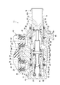
本発明の一実施形態を図面に基づいて説明する。図1に示すマスタシリンダ11は、図示略のブレーキペダルの操作量に応じた力が図示略のブレーキブースタの出力軸を介して導入され、ブレーキペダルの操作量に応じたブレーキ液圧を発生させる。このマスタシリンダ11には、鉛直方向上側にブレーキ液を給排するリザーバ12(図1において一部のみ図示)が取り付けられている。なお、本実施形態においては、マスタシリンダ11に直接リザーバ12を取り付けているが、マスタシリンダ11から離間した位置にリザーバを配置し、リザーバとマスタシリンダ11とを配管で接続するようにしても良い。
マスタシリンダ11は、シリンダ本体15を有している。シリンダ本体15は、底部13と筒部14とを有する有底筒状に一つの素材から加工されて形成される。シリンダ本体15は、第一側が開口部16とされ、第二側が底部13とされている。このシリンダ本体15内の開口部16側には、シリンダ本体15から一部突出して金属製のプライマリピストン18(ピストン)が移動可能に配置されている。また、シリンダ本体15内のプライマリピストン18よりも底部13側には、同じく金属製のセカンダリピストン19(ピストン)が移動可能に配置されている。プライマリピストン18には底面を有する内周孔21が形成されている。セカンダリピストン19には底面を有する内周孔22が形成されている。マスタシリンダ11は、いわゆるプランジャ型である。マスタシリンダ11は、上記したように2つのプライマリピストン18およびセカンダリピストン19を有するタンデムタイプのマスタシリンダである。なお、本発明の実施形態は、上記タンデムタイプのマスタシリンダに限られるものではなく、プランジャ型のマスタシリンダであれば、シリンダ本体に1つのピストンを配したシングルタイプのマスタシリンダや、3つ以上のピストンを有するマスタシリンダ等のいかなるプランジャ型のマスタシリンダにも適用できる。
シリンダ本体15には、その筒部14の中心軸線に直交する径方向(以下、シリンダ径方向と称す)の外側、すなわち中心軸線から遠い側に突出する取付台部23が、その筒部14の円周方向(以下、シリンダ周方向と称す)における所定位置に一体に形成されている。この取付台部23には、リザーバ12を取り付けるための取付穴24および取付穴25が形成されている。なお、本実施形態においては、取付穴24および取付穴25は、互いにシリンダ周方向における位置を一致させた状態で、シリンダ本体15の筒部14の中心軸線(以下、シリンダ軸と称す)方向における位置をずらして鉛直方向上部に形成されている。シリンダ本体15は、シリンダ軸方向が車両前後方向に沿う姿勢で車両に配置される。
シリンダ本体15の筒部14の取付台部23側には、底部13の近傍にブレーキ液の吐出路であるセカンダリ吐出路26(吐出路)が形成されている。また、セカンダリ吐出路26よりもシリンダ本体15の開口部16側にブレーキ液の吐出路であるプライマリ吐出路27(吐出路)が形成されている。これらセカンダリ吐出路26およびプライマリ吐出路27は、図示は略すが、ブレーキ配管を介してディスクブレーキやドラムブレーキ等の制動用シリンダに連通しており、制動用シリンダに向けてブレーキ液を吐出する。なお、本実施形態においては、これらセカンダリ吐出路26およびプライマリ吐出路27が、互いにシリンダ周方向における位置を一致させた状態でシリンダ軸方向における位置をずらして形成されている。
セカンダリ吐出路26およびプライマリ吐出路27には、マスタシリンダ11からブレーキ液をポンプアップして制動用シリンダに向けて吐出する等、制動用シリンダへのブレーキ液圧を制御して車両の姿勢制御や自動緊急ブレーキに用いられる図示略のESC装置が設けられている。
シリンダ本体15の筒部14の底部13側の内周部には、摺動内径部28が形成されている。摺動内径部28は、シリンダ径方向の内方に突出し、シリンダ周方向に環状に形成されている。セカンダリピストン19は、この摺動内径部28の最小内径面28aに摺動可能に嵌合されている。セカンダリピストン19は、この最小内径面28aで案内されてシリンダ軸方向に移動する。シリンダ本体15の筒部14の開口部16側の内周部には、摺動内径部29が形成されている。摺動内径部29は、シリンダ径方向の内方に突出し、シリンダ周方向に環状に形成されている。プライマリピストン18は、この摺動内径部29の最小内径面29aに摺動可能に嵌合されており、この最小内径面29aで案内されてシリンダ軸方向に移動する。
摺動内径部28には、シリンダ軸方向における位置をずらして複数、具体的には2カ所の、いずれも円環状をなす周溝30、周溝31が底部13側からこの順に形成されている。また、摺動内径部29にも、シリンダ軸方向における位置をずらして複数、具体的には2カ所の、いずれも円環状をなす周溝32、周溝33が底部13側からこの順に形成されている。
周溝30,31は、シリンダ周方向に環状をなして最小内径面28aよりもシリンダ径方向の外側に凹む形状を有している。周溝32,33は、シリンダ周方向に環状をなして最小内径面29aよりもシリンダ径方向の外側に凹む形状を有している。周溝30~33は、シリンダ本体15内に形成されている。周溝30~33は、いずれも全体が切削加工により形成されている。
周溝30,31は、シリンダ周方向に環状をなして最小内径面28aよりもシリンダ径方向の外側に凹む形状を有している。周溝32,33は、シリンダ周方向に環状をなして最小内径面29aよりもシリンダ径方向の外側に凹む形状を有している。周溝30~33は、シリンダ本体15内に形成されている。周溝30~33は、いずれも全体が切削加工により形成されている。
周溝30~33のうち最も底部13側にある周溝30は、取付穴24および取付穴25のうちの底部13側の取付穴24の近傍に形成されている。この周溝30内には、周溝30に保持されるように、円環状のピストンシール35(シール部材)が配置されている。
シリンダ本体15の摺動内径部28における周溝30よりも開口部16側には、開口溝37が形成されている。開口溝37は、最小内径面28aよりもシリンダ径方向の外側に凹む環状の溝である。この開口溝37は、底部13側の取付穴24から穿設される連通穴36を筒部14内に開口させる。ここで、この開口溝37と連通穴36とが、シリンダ本体15に設けられてリザーバ12に常時連通するセカンダリ補給路38(補給路)を構成している。言い換えれば、シリンダ本体15は、リザーバ12に連通するセカンダリ補給路38を有している。
シリンダ本体15の摺動内径部28の周溝30よりも底部13側には、連通溝41(溝)が形成されている。連通溝41は、周溝30に開口するとともに周溝30からシリンダ軸方向に直線状に底部13側に向けて延びる。連通溝41(溝)は、最小内径面28aよりもシリンダ径方向の外側に凹むように形成されている。この連通溝41は、底部13と周溝30との間であって底部13の近傍となる位置に形成されたセカンダリ吐出路26と周溝30とを後述のセカンダリ圧力室68を介して連通させる。連通溝41は、周溝30から底部13側に向けてセカンダリ圧力室68に延びている。
シリンダ本体15の摺動内径部28には、シリンダ軸線方向における上記開口溝37の周溝30とは反対側つまり開口部16側に、上記周溝31が形成されている。この周溝31内には、周溝31に保持されるように、円環状の区画シール42が配置されている。
シリンダ本体15の摺動内径部29には、開口部16側の取付穴25の近傍に、上記した周溝32が形成されている。この周溝32内には、周溝32に保持されるように、円環状のピストンシール45(シール部材)が配置されている。
シリンダ本体15の摺動内径部29におけるこの周溝32の開口部16側には、開口溝47が形成されている。開口溝47は、最小内径面29aよりもシリンダ径方向の外側に凹む環状の溝である。この開口溝47は、開口部16側の取付穴25から穿設される連通穴46を筒部14内に開口させる。ここで、この開口溝47と連通穴46とが、シリンダ本体15に設けられてリザーバ12に常時連通するプライマリ補給路48(補給路)を主に構成している。言い換えれば、シリンダ本体15は、リザーバ12に連通するプライマリ補給路48を有している。
シリンダ本体15の摺動内径部29の周溝32よりも底部13側には、連通溝51(溝)が形成されている。連通溝51は、周溝32に開口するとともに周溝32からシリンダ軸方向に直線状に底部13側に向けて延びる。連通溝51(溝)は、最小内径面29aよりもシリンダ径方向の外側に凹むように形成されている。この連通溝51は、周溝31と周溝32との間であって周溝31の近傍となる位置に形成されたプライマリ吐出路27と、周溝32とを後述するプライマリ圧力室85を介して連通させる。連通溝51は、周溝32から底部13側に向けてプライマリ圧力室85に延びている。
シリンダ本体15の摺動内径部29における上記開口溝47の周溝32とは反対側つまり開口部16に周溝33が形成されている。この周溝33内には、周溝33に保持されるように、円環状の区画シール52が配置されている。
シリンダ本体15の底部13側に配置されるセカンダリピストン19は、第1円筒状部55と、第1円筒状部55の軸線方向における一側に形成された底部56と、底部56の第1円筒状部55とは反対側に形成された第2円筒状部57とを有する形状をなしている。上記内周孔22は、第1円筒状部55と底部56とにより形成されている。セカンダリピストン19は、第1円筒状部55をシリンダ本体15の底部13側に配置した状態で、シリンダ本体15の摺動内径部28に設けられたピストンシール35および区画シール42のそれぞれの内周に摺動可能に嵌合される。
第1円筒状部55の底部56とは反対の端側外周部には、円環状の凹部59が形成されている。凹部59は、セカンダリピストン19の外周面19Aにおいて最も大径の最大外径面19aよりも径方向内方に凹む。この凹部59には、その底部56側にシリンダ径方向に貫通するポート60が複数、シリンダ周方向の等間隔位置に放射状に形成されている。
セカンダリピストン19とシリンダ本体15の底部13との間には、間隔調整部63が設けられている。間隔調整部63は、図示略のブレーキブースタの出力軸から入力がない非制動状態でこれらの間隔を決めるセカンダリピストンスプリング62を含む。この間隔調整部63は、シリンダ本体15の底部13に当接する係止部材64と、この係止部材64に所定範囲内でのみ摺動するように連結されてセカンダリピストン19の底部56に当接する係止部材65とを有している。上記セカンダリピストンスプリング62は、係止部材64と係止部材65との間に介装されている。
シリンダ本体15の底部13および筒部14の底部13側とセカンダリピストン19とで囲まれて形成される部分が、ブレーキ液圧を発生してセカンダリ吐出路26にブレーキ液圧を供給するセカンダリ圧力室68(圧力室)を構成する。言い換えれば、セカンダリピストン19は、シリンダ本体15との間に、セカンダリ吐出路26に液圧を供給するセカンダリ圧力室68を形成している。このセカンダリ圧力室68は、セカンダリピストン19がポート60をセカンダリ補給路38に開口させる位置にあるとき、セカンダリ補給路38つまりリザーバ12に連通する。
シリンダ本体15の周溝31に保持される区画シール42は、合成ゴムからなる一体成形品である。区画シール42は、その中心線を含む径方向断面の片側形状がC字状をなしている。区画シール42は、内周が、シリンダ軸方向に移動するセカンダリピストン19の外周面19Aに摺接するとともに、外周がシリンダ本体15の周溝31に当接する。これにより、区画シール42は、セカンダリピストン19およびシリンダ本体15の区画シール42の位置の隙間を常時密封する。
シリンダ本体15の周溝30に保持されるピストンシール35は、EPDM等の合成ゴムからなる一体成形品である。ピストンシール35は、その中心線を含む径方向断面の片側形状がE字状をなしている。ピストンシール35の内周は、シリンダ軸方向に移動するセカンダリピストン19の外周面19Aに摺接する。また、ピストンシール35の外周は、シリンダ本体15の周溝30に当接する。周溝30に設けられるこのピストンシール35は、セカンダリピストン19がポート60をピストンシール35よりも底部13側に位置させた状態では、セカンダリ補給路38とセカンダリ圧力室68との間を密封可能に構成されている。つまり、ピストンシール35は、セカンダリ圧力室68と、セカンダリ補給路38およびリザーバ12との連通を遮断して密封することが可能となっている。この密封状態で、セカンダリピストン19が、シリンダ本体15の摺動内径部28およびシリンダ本体15に保持されたピストンシール35および区画シール42の内周で摺動して底部13側に移動することによって、セカンダリ圧力室68内のブレーキ液が加圧される。セカンダリ圧力室68内で加圧されたブレーキ液は、セカンダリ吐出路26から車輪側の制動用シリンダに供給される。
図示略のブレーキブースタの出力軸から入力がなく、上述のセカンダリピストン19が図1に示すようにポート60をセカンダリ補給路38に開口させる基本位置(非制動位置)にあるときに、ピストンシール35は、上記セカンダリピストン19の凹部59内にあって、ポート60にその一部がシリンダ軸方向に重複する。そして、セカンダリピストン19がシリンダ本体15の底部13側へ移動してピストンシール35の内周部がポート60に全て重なると、セカンダリ圧力室68とリザーバ12との連通が遮断される。
シリンダ本体15の開口部16側に配置されるプライマリピストン18は、第1円筒状部71と、第1円筒状部71の軸線方向における一側に形成された底部72と、底部72の第1円筒状部71とは反対側に形成された第2円筒状部73とを有する形状をなしている。上記内周孔21は、第1円筒状部71と底部72とにより形成されている。プライマリピストン18は、第1円筒状部71をシリンダ本体15内のセカンダリピストン19側に配置した状態で、シリンダ本体15の摺動内径部29に設けられたピストンシール45および区画シール52のそれぞれの内周に摺動可能に嵌合される。第2円筒状部73の内側には、図示略のブレーキブースタの出力軸が挿入される。この出力軸によって底部72が押圧される。
第1円筒状部71の底部72とは反対の端側外周部には、円環状の凹部75が形成されている。凹部75は、プライマリピストン18の外周面18Aにおいて最も大径の最大外径面18aよりも径方向内方に凹む。この凹部75には、その底部72側に径方向に貫通するポート76が複数、シリンダ周方向の等間隔位置に、放射状に形成されている。
セカンダリピストン19とプライマリピストン18との間には、間隔調整部79が設けられている。間隔調整部79は、図示略のブレーキブースタの出力軸から入力がない非制動状態でこれらの間隔を決めるプライマリピストンスプリング78を含む。この間隔調整部79は、プライマリピストン18の底部72に当接する係止部材81と、セカンダリピストン19の底部56に当接する係止部材82と、係止部材81に一端部が固定されるとともに係止部材82を所定範囲内でのみ摺動自在に支持する軸部材83とを有している。上記プライマリピストンスプリング78は、係止部材81と係止部材82との間に介装されている。
ここで、シリンダ本体15の筒部14とプライマリピストン18とセカンダリピストン19とで囲まれて形成される部分が、ブレーキ液圧を発生してプライマリ吐出路27にブレーキ液を供給するプライマリ圧力室85(圧力室)を構成する。言い換えれば、プライマリピストン18は、セカンダリピストン19およびシリンダ本体15との間に、プライマリ吐出路27に液圧を供給するプライマリ圧力室85を形成している。このプライマリ圧力室85は、プライマリピストン18がポート76をプライマリ補給路48に開口させる位置にあるとき、プライマリ補給路48つまりリザーバ12に連通する。
シリンダ本体15の周溝33に保持される区画シール52は、区画シール42と共通の部品である。区画シール52は、合成ゴムからなる一体成形品である。区画シール52は、その中心線を含む径方向断面の片側形状がC字状をなしている。区画シール52は、内周が、シリンダ軸方向に移動するプライマリピストン18の外周面18Aに摺接するとともに、外周がシリンダ本体15の周溝33に当接する。これにより、区画シール52は、プライマリピストン18およびシリンダ本体15の区画シール52の位置の隙間を常時密封する。
シリンダ本体15の周溝32に保持されるピストンシール45は、ピストンシール35と共通の部品である。ピストンシール45は、EPDM等の合成ゴムからなる一体成形品である。ピストンシール45は、その中心線を含む径方向断面の片側形状がE字状をなしている。ピストンシール45の内周は、シリンダ軸方向に移動するプライマリピストン18の外周面18Aに摺接する。ピストンシール45の外周は、シリンダ本体15の周溝32に当接する。周溝32に設けられるこのピストンシール45は、プライマリピストン18がポート76をピストンシール45よりも底部13側に位置させた状態では、プライマリ補給路48とプライマリ圧力室85との間を密封可能となっている。つまり、ピストンシール45は、プライマリ圧力室85と、プライマリ補給路48およびリザーバ12との連通を遮断して密封することが可能となっている。この密封状態で、プライマリピストン18が、シリンダ本体15の摺動内径部29およびシリンダ本体15に保持されたピストンシール45および区画シール52の内周で摺動して底部13側に移動することによって、プライマリ圧力室85内のブレーキ液が加圧される。プライマリ圧力室85内で加圧されたブレーキ液は、プライマリ吐出路27から車輪側の制動用シリンダに供給される。
図示略のブレーキブースタの出力軸から入力がなく、プライマリピストン18が図1に示すようにポート76をプライマリ補給路48に開口させる基本位置(非制動位置)にあるときに、ピストンシール45は、上記プライマリピストン18の凹部75内にあって、ポート76にその一部がシリンダ軸方向に重複する。そして、プライマリピストン18がシリンダ本体15の底部13側へ移動してピストンシール45の内周部がポート76に全て重なると、プライマリ圧力室85とリザーバ12との連通が遮断される。
ここで、シリンダ本体15の周溝30、連通溝41およびこれらの近傍部分と、ピストンシール35と、ピストンシール35の摺接部分である、セカンダリピストン19の凹部59およびポート60を含む第1円筒状部55の先端部分とからなる構造部を、セカンダリ補給路38とセカンダリ圧力室68との連通および遮断を切り替えるセカンダリ側のシール構造部SSと称する。また、シリンダ本体15の周溝32、連通溝51およびこれらの近傍部分と、ピストンシール45と、ピストンシール45の摺接部分である、プライマリピストン18の凹部75およびポート76を含む第1円筒状部71の先端部分とからなる構造部を、プライマリ補給路48とプライマリ圧力室85との連通および遮断を切り替えるプライマリ側のシール構造部SPと称する。
ピストンシール35およびピストンシール45は同形状の共通部品である。周溝30および連通溝41は、周溝32および連通溝51と同形状である。凹部59およびポート60は、凹部75およびポート76と同形状であって、セカンダリ側のシール構造部SSとプライマリ側のシール構造部SPとは同様の構造である。したがって、以下においては、これらの詳細についてプライマリ側のシール構造部SPを例にとり、主に図2~図4を参照して説明する。シリンダ軸方向におけるシリンダ本体15の開口部16側を、シリンダ開口側と称する。シリンダ軸方向におけるシリンダ本体15の底部13側を、シリンダ底側と称す。
図2に示すように、周溝32は、その凹み方向の奥側、すなわちシリンダ径方向の外側に溝底88を有している。また、周溝32は、周壁89を有している。周壁89は、溝底88におけるシリンダ開口側の端縁部からシリンダ径方向の内方に延出する。さらに、周溝32は、周壁90を有している。周壁90は、溝底88におけるシリンダ底側の端縁部からシリンダ径方向の内方に延出する。これら溝底88、周壁89および周壁90は、シリンダ本体15自体に形成されている。溝底88、周壁89および周壁90は、シリンダ本体15に対する切削加工により形成されている。
溝底88は溝底面部88aを有している。溝底面部88aは、シリンダ軸を中心とする円筒面であり、シリンダ軸方向の長さがシリンダ周方向の全周に亘って一定となっている。
周溝32のシリンダ開口側の周壁89は、シリンダ軸の直交面に平行な平坦面からなる壁面部89aを有している。壁面部89aは、溝底面部88aのシリンダ開口側の端縁部からシリンダ径方向の内方に広がっている。壁面部89aは、シリンダ周方向の全周に亘って、一定内径かつ一定外径でシリンダ径方向に一定幅である。壁面部89aは、シリンダ軸を中心とする円環状をなしている。
周溝32のシリンダ底側の周壁90は、周壁89に対し、シリンダ径方向の位置を重ね合わせてシリンダ軸方向に対向している。周壁90は、シリンダ径方向の外側、すなわち周溝32の径方向の外側の傾斜部91と、シリンダ径方向の内側、すなわち周溝32の径方向の内側の軸直交部92とを有している。
傾斜部91は、傾斜壁面部91aを有している。傾斜壁面部91aは、溝底面部88aのシリンダ底側の端縁部から周溝32の径方向の内方に向けて、径方向の内側ほどシリンダ軸方向においてシリンダ底側に位置するように傾斜して延出する。傾斜壁面部91aは、テーパ面である。傾斜壁面部91aは、言い換えれば、周溝32の溝底88のシリンダ底側の端部から、周溝32の径方向の内側に向けて形成された面であって、周溝32の径方向の内側になるにつれてシリンダ底側になるように傾斜している。よって、傾斜部91は、溝底88のシリンダ底側の端縁部から周溝32の径方向の内方に向けて周溝32の径方向の内側ほどシリンダ底側に位置するように傾斜して延出している。さらに言い換えれば、溝底88は片側の軸方向端部がテーパ面である傾斜壁面部91a、すなわち傾斜部91で埋められた形状となっている。
軸直交部92は、軸直交壁面部92aと、R面取面92bと、を有している。軸直交壁面部92aは、周溝32の径方向における傾斜壁面部91aの内側の端縁部から、シリンダ軸に対し直交する面に平行なして周溝32の径方向の内側に広がる平坦面から構成されている。R面取面92bは、周溝32の径方向における軸直交壁面部92aの内側の端縁部と周溝32よりもシリンダ底側の摺動内径部29の最小内径面29aとを繋ぐ湾曲面から構成されている。
ここで、上記した連通溝51は、傾斜部91の傾斜壁面部91aと、軸直交部92の軸直交壁面部92aおよびR面取面92bと、周溝32よりもシリンダ底側の摺動内径部29の最小内径面29aとに連続して開口している。よって、シリンダ本体15には、傾斜部91に開口して周溝32からシリンダ底側に向けて延びる連通溝51が形成されている。連通溝51は、傾斜部91の傾斜壁面部91aに対しては、周溝32の径方向における中間位置から内側の一部のみに開口している。言い換えれば、シリンダ径方向において、連通溝51は、最も深さが深い最深部51aの位置が、傾斜壁面部91aの中間部と一致している。
傾斜壁面部91aは、連通溝51の開口部分を除き、シリンダ周方向の全周に亘って、一定内径かつ一定外径でシリンダ径方向に一定幅となっている。傾斜壁面部91aは、シリンダ軸を中心とする円環状をなしている。軸直交壁面部92aも、連通溝51の開口部分を除き、シリンダ周方向の全周に亘って、一定内径かつ一定外径でシリンダ径方向に一定幅となっており、シリンダ軸を中心とする円環状をなしている。
プライマリピストン18の第1円筒状部71に形成された凹部75は、円筒面75aとテーパ面75bとテーパ面75cとを有している。円筒面75aは、プライマリピストン18において最も大径である円筒面状の最大外径面18aよりも小径となっており、全周にわたって軸方向に一定幅となっている。テーパ面75bは、円筒面75aのシリンダ開口側の端縁部からシリンダ開口側ほど大径となるように傾斜して延出し、最大外径面18aの凹部75よりもシリンダ開口側の部分に繋がっている。プライマリ圧力室85に常時連通するポート76は、テーパ面75b内のシリンダ開口側に形成されており、そのシリンダ開口側の端部がテーパ面75bのシリンダ開口側の端部と一致している。テーパ面75bは、ポート76の形成部分を除いて軸方向に一定幅となっている。テーパ面75cは、円筒面75aのシリンダ底側の端縁部からシリンダ底側ほど大径となるように傾斜して延出し、最大外径面18aの凹部75よりもシリンダ底側の部分に繋がっている。テーパ面75cは、全周に亘って軸方向に一定幅となっている。
これら円筒面75a、テーパ面75bおよびテーパ面75cは、最大外径面18aと同様にプライマリピストン18の中心軸を中心に形成されている。テーパ面75bはテーパ面75cよりも軸方向の長さが長い。よって、テーパ面75bはテーパ面75cよりも小さいテーパとなっている。
周溝32に配置されるピストンシール45は、ベース部101と内周リップ部102と外周リップ部103と中間リップ部104とを有している。ベース部101は、ピストンシール45におけるシリンダ開口側に配置されている。ベース部101は、ピストンシール45の軸直交面に平行な円環板状をなしている。内周リップ部102は、ベース部101の内周端縁部からシリンダ軸方向に沿ってシリンダ底側に向け延出する円環筒状をなしている。外周リップ部103は、ベース部101の外周端縁部からシリンダ軸方向に沿ってシリンダ底側に向けて延出する円環筒状をなしている。中間リップ部104は、外周リップ部103と内周リップ部102との間にあってベース部101からシリンダ軸方向に沿ってシリンダ底側に向けて突出する円環筒状をなしている。中間リップ部104、内周リップ部102および外周リップ部103は、ベース部101からのシリンダ軸方向の突出量がほぼ同等になっている。
ピストンシール45の内周リップ部102は、シリンダ軸方向に移動するプライマリピストン18の、上記した円筒面75a、テーパ面75b、テーパ面75cおよび最大外径面18aを含む外周面18Aに摺接する。ピストンシール45の外周リップ部103は、シリンダ本体15の周溝32の溝底88の溝底面部88aに当接する。言い換えれば、ピストンシール45は、プライマリピストン18の外周面18Aに摺接する内周リップ部102と、シリンダ本体15の周溝32に当接する外周リップ部103と、これらの間の中間リップ部104と、これらが突出して設けられる円環状のベース部101と、を有している。ピストンシール45は、ベース部101のシリンダ開口側の端面101aが、周壁89の壁面部89aに当接可能となっている。
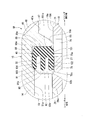
図2は、図示略のブレーキブースタの出力軸側から入力がないマスタシリンダ11の基本状態(ブレーキペダルが操作される前の非制動状態)を示している。この基本状態にあるとき、ピストンシール45の内周リップ部102は、プライマリピストン18の凹部75の円筒面75aおよびテーパ面75bに密着しており、外周リップ部103は、周溝32の溝底88の溝底面部88aに当接している。また、この基本状態にあるとき、ピストンシール45は、ベース部101の端面101aが周壁89の壁面部89aに当接している。
マスタシリンダ11が基本状態にあるとき、プライマリピストン18は、図2に示す基本位置(非制動位置)に位置する。プライマリピストン18がこの基本位置にあるときに、ポート76はプライマリ補給路48に連通している。プライマリピストン18が基本位置にあるときに、ピストンシール45は、その内周リップ部102がプライマリピストン18の凹部75の円筒面75aの位置にあり、ベース部101がテーパ面75bの位置にあって、ベース部101の内周部がポート76のシリンダ底側の一部にシリンダ軸方向の位置を重ね合わせている。
マスタシリンダ11が基本状態にあるとき、ピストンシール45は、外周リップ部103が周溝32の傾斜部91の傾斜壁面部91aとシリンダ径方向の位置を重ね合わせてシリンダ軸方向に対向し当接している。言い換えれば、ピストンシール45は、シリンダ底側に移動した際に外周リップ部103の先端が傾斜部91と当接する位置に配置されている。また、この基本状態で、外周リップ部103は、連通溝51の最深部51aの位置とシリンダ径方向の位置を重ね合わせてシリンダ軸方向に対向している。また、この基本状態では、中間リップ部104が軸直交部92の軸直交壁面部92aとシリンダ径方向の位置を重ね合わせてシリンダ軸方向に対向して離間しており、内周リップ部102が軸直交部92の軸直交壁面部92aおよびR面取面92bとシリンダ径方向の位置を重ね合わせてシリンダ軸方向に対向して離間している。
そして、通常制動時に、図示略のブレーキブースタの出力軸側から入力があって、プライマリピストン18が基本位置からシリンダ底側へ移動すると、ピストンシール45は、プライマリピストン18とともに周溝32内で周壁90側に移動する。その結果、ピストンシール45は、内周リップ部102の先端部および中間リップ部104の先端部において周壁90の軸直交壁面部92aに当接して、シリンダ底側への移動が規制される。なお、ピストンシール45が周溝32内で周壁90側に移動すると、外周リップ部103は、傾斜部91の傾斜壁面部91aに当接するその先端部が、この傾斜壁面部91aの傾斜によって、周溝32の径方向の内方に移動する。また、ベース部101の端面101aが周壁89の壁面部89aから離れる。
プライマリピストン18が、さらにシリンダ底側へ移動すると、周壁90の軸直交壁面部92aに当接してシリンダ底側への移動が規制されているピストンシール45は、移動するプライマリピストン18に対し、その外周面18Aを摺動して、ベース部101および内周リップ部102が凹部75のテーパ面75bをシリンダ開口側に移動する。
プライマリピストン18が、さらにシリンダ底側へ移動すると、プライマリピストン18の外周面18Aを摺接するピストンシール45は、ポート76を越えポート76を閉塞して、プライマリ圧力室85とプライマリ補給路48とのポート76を介しての連通を遮断した後、全体としてプライマリピストン18の最大外径面18aのシリンダ開口側の部分に乗り上げる。
上記のようにピストンシール45が、プライマリ圧力室85とプライマリ補給路48とのポート76を介しての連通を遮断する位置からプライマリピストン18がシリンダ底側に位置する範囲では、基本的に、大気圧であるプライマリ補給路48の液圧よりもプライマリ圧力室85の液圧の方が高くなる。すると、この液圧差で、ピストンシール45は、外周リップ部103が溝底88の溝底面部88aに全周に亘って押し付けられる。これにより、常時プライマリピストン18に押し付けられている内周リップ部102およびこれらを結ぶベース部101とで、プライマリ圧力室85とプライマリ補給路48との間の周溝32とプライマリピストン18との間を介しての連通を遮断する。これにより、プライマリ圧力室85を密封する。その結果、プライマリ圧力室85内の液圧が上昇しプライマリ圧力室85内のブレーキ液が図1に示すプライマリ吐出路27から車輪側の制動用シリンダに供給される。
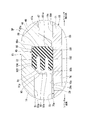
ピストンシール45は、上記したプライマリ圧力室85の液圧上昇によって周溝32内でプライマリ補給路48側つまり周壁89側に移動する。すると、中間リップ部104および内周リップ部102が周壁90から離れた後、図3に示すように、ベース部101が端面101aにおいて周壁89の壁面部89aに当接する。この間も、ピストンシール45は、プライマリ圧力室85とプライマリ補給路48との液圧差で、外周リップ部103が溝底88の溝底面部88aに全周に亘って押し付けられた状態を維持する。これにより、プライマリ圧力室85とプライマリ補給路48との周溝32とプライマリピストン18との間を介しての連通を遮断する。
プライマリピストン18がシリンダ底側へ移動した状態から、制動を解除するために図示略のブレーキペダルを戻すと、図1に示す間隔調整部63の付勢力によってシリンダ開口側に移動するプライマリピストン18と、図1に示す間隔調整部79の付勢力とによって、プライマリピストン18が図2に示す基本位置に戻る。
図3に示すように、プライマリピストン18がポート76をピストンシール45よりシリンダ底側に位置させた液圧保持状態で、ESC装置によるポンプアップによってプライマリ圧力室85内の液圧が低下すると、大気圧であるプライマリ補給路48の液圧とプライマリ圧力室85の液圧とが等しくなった後、プライマリ圧力室85内の液圧は負圧となり、大気圧であるプライマリ補給路48の液圧よりもプライマリ圧力室85の液圧の方が低くなる。
すると、このプライマリ圧力室85内の負圧が、図4に示すように、ピストンシール45を吸引して周壁90側に移動させてベース部101を周壁89から離間させるとともに、ピストンシール45の外周リップ部103を周溝32の溝底88から離間させる。しかも、このピストンシール45の周壁90側への移動で、外周リップ部103は、傾斜部91の傾斜壁面部91aに当接するその先端部が、この傾斜壁面部91aの傾斜によって、シリンダ径方向の内方に移動する。すると、外周リップ部103は、ベース部101側を中心としてシリンダ径方向の内方に倒れ込み、周壁90への当接位置が連通溝51の最深部51aよりもシリンダ径方向の内側に位置する。これにより、連通溝51が周溝32の溝底88とピストンシール45との間の部分に連通する。
その結果、プライマリ補給路48のブレーキ液が、図4に破線矢印Xで示すように、周壁89とベース部101との隙間と、溝底88と外周リップ部103との隙間と、連通溝51内の通路とを介して、プライマリ圧力室85に補給される。これにより、ESC装置によるポンプアップに対して、大流量でブレーキ液を補給することができる。
なお、ピストンシール45の周壁90側への移動時に、外周リップ部103は、傾斜壁面部91aを基点として変形するため、姿勢が安定する。よって、溝底88と外周リップ部103との隙間と、連通溝51内の通路とを安定した通路面積で連通させることができる。
ここで、マスタシリンダ11においては、プライマリピストン18がポート76をプライマリ補給路48に開口させた状態でのプライマリ補給路48からプライマリ圧力室85へのブレーキ液の流量である静的フローレートより、プライマリピストン18がポート76をプライマリ補給路48に開口させない状態でのプライマリ補給路48からプライマリ圧力室85へのブレーキ液の流量である動的フローレートの方が、ポート76が閉じられているため低い。本実施形態のマスタシリンダ11は、この動的フローレートを向上することができる。
上記した特許文献1に記載のマスタシリンダは、シール部材が配置される周溝に、シール部材のセンタリップ部の径方向外方への移動を規制する傾斜面を形成している。ところで、圧力室からリザーバへのブレーキ液の流通を遮断するとともに逆方向のブレーキ液の流通を許容するシール部材を有するマスタシリンダにおいて、ブレーキ液流通時の流量を増大させる要望がある。上記のマスタシリンダでは、リザーバから圧力室へのブレーキ液の流通時に、シール部材の外周リップ部が周溝の溝底から離れてブレーキ液を流す。しかしながら、圧力室側に吸引されたシール部材は、周溝内で圧力室側に移動して周溝のシリンダ底側の周壁に当接する。このシール部材の周壁への当接によって、リザーバから圧力室へのブレーキ液の流量を所望のようには増大できない可能性がある。
これに対して、本実施形態のマスタシリンダ11は、周溝32が、溝底88におけるシリンダ底側の端部から周溝32の径方向の内方に向けて径方向の内側ほどシリンダ底側に位置するように傾斜して延出する傾斜部91を有している。このため、プライマリ圧力室85の液圧が下がり、ピストンシール45がプライマリ圧力室85側に吸引されてシリンダ底側に移動すると、その外周リップ部103が傾斜部91の傾斜で案内されて径方向の内方に変形する。これにより、傾斜部91に開口する連通溝51を外周リップ部103と溝底88との間に連通させることができ、ブレーキ液流通時の流量を増大させることができる。
また、このようにブレーキ液流通時の流量を増大させることができる結果、ブレーキペダルの早戻しにてプライマリ圧力室85が負圧状態となるが、プライマリピストン18のポート76がプライマリ補給路48まで達することにより、プライマリ圧力室85の負圧が急激に解除されることで生じるウォータハンマノイズを低減することができる。
また、ピストンシール45は、シリンダ底側に移動した際に外周リップ部103の先端が傾斜部91と当接する位置に配置されている。このため、ピストンシール45がプライマリ圧力室85側に吸引されてシリンダ底側に移動したときに、その外周リップ部103を傾斜部91の傾斜で円滑に周溝32の径方向の内方に変形させることができる。これにより、傾斜部91に開口する連通溝51を外周リップ部103と溝底88との間に円滑に連通させることができ、ブレーキ液流通時の流量を円滑に増大させることができる。
ピストンシール45がシリンダ底側に移動した際に、外周リップ部103は、周溝32の傾斜部91を基点として倒れるため、ピストンシール45の姿勢を安定させることができる。
上記のように傾斜部91に開口する連通溝51を外周リップ部103と溝底88との間に連通させることができるため、ピストンシール45の中間リップ部104の先端部に流路形成用の溝を形成しなくても済み、中間リップ部104の強度を向上させることができる。
なお、以上の実施形態においては、ピストンシール45と、シリンダ本体15の周溝32および連通溝51と、凹部75およびポート76を有する第1円筒状部71と、を含むプライマリ側のシール構造部SPを例にとり詳細に説明したが、ピストンシール45と同形状のピストンシール35と、周溝32および連通溝51と同形状の周溝30および連通溝41と、凹部75およびポート76と同形状の凹部59およびポート60と、を含むセカンダリ側のシール構造部SSも同様の構造で同様に動作する。よって、シール構造部SSもシール構造部SPと同様の効果を奏する。
また、以上の実施形態においては、ベース部101、内周リップ部102、外周リップ部103および中間リップ部104を有する断面E字状のピストンシール35,45を例にとり説明したが、上記構成は、ベース部と内周リップ部と外周リップ部とからなり、中間リップ部のない断面C字状のピストンシールを使用する場合についても有効である。
以上の実施形態の第1の態様によれば、マスタシリンダは、一側が開口部とされ他側が底部とされる有底筒状をなしてブレーキ液の吐出路とリザーバに連通する補給路とを有するシリンダ本体と、該シリンダ本体内に移動可能に配置され、該シリンダ本体との間に前記吐出路から液圧を供給する圧力室を形成するピストンと、前記シリンダ本体内に形成される周溝内に設けられ前記補給路と前記圧力室との間を密封可能なシール部材とを有する。前記シール部材は、前記周溝における前記開口部側の周壁に当接可能なベース部と、該ベース部から前記底部側に向けて延出して前記ピストンの外周に摺接する内周リップ部と、前記ベース部から前記底部側に向けて延出して前記周溝の溝底に当接する外周リップ部と、を有する。前記周溝は、前記溝底の前記底部側の端部から径方向内方に向けて径方向内側ほど前記底部側に位置するように傾斜する傾斜部を有する。前記シリンダ本体には、前記傾斜部に開口して前記周溝から前記底部側に向けて前記圧力室に延びる溝が形成されている。これにより、ブレーキ液流通時の流量を増大させることが可能となる。
第2の態様によれば、上記第1の態様において、前記シール部材は、前記底部側に移動した際に前記外周リップ部の先端が前記傾斜部と当接する位置に配置されていてもよい。これにより、ブレーキ液流通時の流量を円滑に増大させることが可能となる。
上記したマスタシリンダによれば、ブレーキ液流通時の流量を増大させることが可能となる。
11 マスタシリンダ
12 リザーバ
13 底部
15 シリンダ本体
16 開口部
18 プライマリピストン(ピストン)
19 セカンダリピストン(ピストン)
26 セカンダリ吐出路(吐出路)
27 プライマリ吐出路(吐出路)
30,32 周溝
35,45 ピストンシール(シール部材)
38 セカンダリ補給路(補給路)
41,51 連通溝(溝)
48 プライマリ補給路(補給路)
68 セカンダリ圧力室(圧力室)
85 プライマリ圧力室(圧力室)
88 溝底
89 周壁
91 傾斜部
101 ベース部
102 内周リップ部
103 外周リップ部
12 リザーバ
13 底部
15 シリンダ本体
16 開口部
18 プライマリピストン(ピストン)
19 セカンダリピストン(ピストン)
26 セカンダリ吐出路(吐出路)
27 プライマリ吐出路(吐出路)
30,32 周溝
35,45 ピストンシール(シール部材)
38 セカンダリ補給路(補給路)
41,51 連通溝(溝)
48 プライマリ補給路(補給路)
68 セカンダリ圧力室(圧力室)
85 プライマリ圧力室(圧力室)
88 溝底
89 周壁
91 傾斜部
101 ベース部
102 内周リップ部
103 外周リップ部
Claims (2)
- 第一側が開口部とされ第二側が底部とされる有底筒状をなして、ブレーキ液の吐出路とリザーバに連通する補給路とを有するシリンダ本体と、
該シリンダ本体内に移動可能に配置され、該シリンダ本体との間に前記吐出路から液圧を供給する圧力室を形成するピストンと、
前記シリンダ本体内に形成される周溝内に設けられ前記補給路と前記圧力室との間を密封可能なシール部材と、
を備え、
前記シール部材は、
前記周溝における前記開口部側の周壁に当接可能なベース部と、
該ベース部から前記底部側に向けて延出して前記ピストンの外周に摺接する内周リップ部と、
前記ベース部から前記底部側に向けて延出して前記周溝の溝底に当接する外周リップ部と、を有し、
前記周溝は、前記溝底の前記底部側の端部から径方向内方に向けて径方向内側ほど前記底部側に位置するように傾斜する傾斜部を有し、
前記シリンダ本体には、前記傾斜部に開口して前記周溝から前記底部側に向けて前記圧力室に延びる溝が形成されている
マスタシリンダ。 - 前記シール部材は、前記底部側に移動した際に前記外周リップ部の先端が前記傾斜部と当接する位置に配置されている
請求項1記載のマスタシリンダ。
Priority Applications (4)
| Application Number | Priority Date | Filing Date | Title |
|---|---|---|---|
| MX2020002203A MX2020002203A (es) | 2017-08-29 | 2018-06-13 | Cilindro maestro. |
| CN201880053808.2A CN111225839B (zh) | 2017-08-29 | 2018-06-13 | 主缸 |
| JP2019538998A JP6749499B2 (ja) | 2017-08-29 | 2018-06-13 | マスタシリンダ |
| DE112018004880.2T DE112018004880B4 (de) | 2017-08-29 | 2018-06-13 | Hauptzylinder |
Applications Claiming Priority (2)
| Application Number | Priority Date | Filing Date | Title |
|---|---|---|---|
| JP2017-164362 | 2017-08-29 | ||
| JP2017164362 | 2017-08-29 |
Publications (1)
| Publication Number | Publication Date |
|---|---|
| WO2019044115A1 true WO2019044115A1 (ja) | 2019-03-07 |
Family
ID=65525841
Family Applications (1)
| Application Number | Title | Priority Date | Filing Date |
|---|---|---|---|
| PCT/JP2018/022581 Ceased WO2019044115A1 (ja) | 2017-08-29 | 2018-06-13 | マスタシリンダ |
Country Status (5)
| Country | Link |
|---|---|
| JP (1) | JP6749499B2 (ja) |
| CN (1) | CN111225839B (ja) |
| DE (1) | DE112018004880B4 (ja) |
| MX (1) | MX2020002203A (ja) |
| WO (1) | WO2019044115A1 (ja) |
Cited By (1)
| Publication number | Priority date | Publication date | Assignee | Title |
|---|---|---|---|---|
| US20230036957A1 (en) * | 2020-01-07 | 2023-02-02 | Kinetic Pressure Control Ltd. | Seals for multi-surface sealing |
Families Citing this family (1)
| Publication number | Priority date | Publication date | Assignee | Title |
|---|---|---|---|---|
| JP7609650B2 (ja) * | 2021-02-10 | 2025-01-07 | カヤバ株式会社 | 流体圧シリンダ |
Citations (4)
| Publication number | Priority date | Publication date | Assignee | Title |
|---|---|---|---|---|
| JP2001130398A (ja) * | 1999-11-10 | 2001-05-15 | Aisin Seiki Co Ltd | ブレーキマスタシリンダ |
| JP2011136602A (ja) * | 2009-12-25 | 2011-07-14 | Hitachi Automotive Systems Ltd | マスタシリンダ |
| JP2013226979A (ja) * | 2012-04-26 | 2013-11-07 | Hitachi Automotive Systems Ltd | マスタシリンダ |
| US20150298673A1 (en) * | 2010-12-21 | 2015-10-22 | Robert Bosch Gmbh | Brake sysytem master-cylinder seal |
Family Cites Families (9)
| Publication number | Priority date | Publication date | Assignee | Title |
|---|---|---|---|---|
| DE2343750A1 (de) * | 1973-08-30 | 1975-03-13 | Freudenberg Carl Fa | Primaerabdichtung mit ventilwirkung fuer hauptbremszylinder |
| DE10053571B4 (de) * | 2000-10-28 | 2005-06-23 | Zf Sachs Ag | Primärdichtungen für Geber-Nehmerzylinder-Systeme |
| JP2003312466A (ja) * | 2002-04-25 | 2003-11-06 | Advics:Kk | マスタシリンダ |
| KR20090055624A (ko) | 2006-10-23 | 2009-06-02 | 봇슈 가부시키가이샤 | 컵 시일 및 이것을 사용한 마스터 실린더 |
| JP5201648B2 (ja) * | 2006-10-31 | 2013-06-05 | ボッシュ株式会社 | カップシールおよびこれを用いたマスタシリンダ |
| CN104220311B (zh) | 2012-05-31 | 2016-06-29 | 日立汽车系统株式会社 | 主缸 |
| WO2014119611A1 (ja) * | 2013-01-31 | 2014-08-07 | 日立オートモティブシステムズ株式会社 | マスタシリンダ |
| JP6366185B2 (ja) | 2014-11-28 | 2018-08-01 | 日立オートモティブシステムズ株式会社 | マスタシリンダ |
| JP2017164362A (ja) | 2016-03-17 | 2017-09-21 | 株式会社高尾 | 弾球遊技機 |
-
2018
- 2018-06-13 CN CN201880053808.2A patent/CN111225839B/zh active Active
- 2018-06-13 JP JP2019538998A patent/JP6749499B2/ja active Active
- 2018-06-13 MX MX2020002203A patent/MX2020002203A/es unknown
- 2018-06-13 DE DE112018004880.2T patent/DE112018004880B4/de active Active
- 2018-06-13 WO PCT/JP2018/022581 patent/WO2019044115A1/ja not_active Ceased
Patent Citations (4)
| Publication number | Priority date | Publication date | Assignee | Title |
|---|---|---|---|---|
| JP2001130398A (ja) * | 1999-11-10 | 2001-05-15 | Aisin Seiki Co Ltd | ブレーキマスタシリンダ |
| JP2011136602A (ja) * | 2009-12-25 | 2011-07-14 | Hitachi Automotive Systems Ltd | マスタシリンダ |
| US20150298673A1 (en) * | 2010-12-21 | 2015-10-22 | Robert Bosch Gmbh | Brake sysytem master-cylinder seal |
| JP2013226979A (ja) * | 2012-04-26 | 2013-11-07 | Hitachi Automotive Systems Ltd | マスタシリンダ |
Cited By (3)
| Publication number | Priority date | Publication date | Assignee | Title |
|---|---|---|---|---|
| US20230036957A1 (en) * | 2020-01-07 | 2023-02-02 | Kinetic Pressure Control Ltd. | Seals for multi-surface sealing |
| US12297910B2 (en) * | 2020-01-07 | 2025-05-13 | Kinetic Pressure Control Ltd. | Seals for multi-surface sealing |
| AU2021206211B2 (en) * | 2020-01-07 | 2026-06-18 | Kinetic Pressure Control Ltd. | Seals for multi-surface sealing |
Also Published As
| Publication number | Publication date |
|---|---|
| DE112018004880T5 (de) | 2020-06-10 |
| JPWO2019044115A1 (ja) | 2020-04-23 |
| JP6749499B2 (ja) | 2020-09-02 |
| DE112018004880B4 (de) | 2021-10-07 |
| CN111225839A (zh) | 2020-06-02 |
| MX2020002203A (es) | 2020-10-05 |
| CN111225839B (zh) | 2022-06-17 |
Similar Documents
| Publication | Publication Date | Title |
|---|---|---|
| US7401468B2 (en) | Master cylinder | |
| US10183657B2 (en) | Master cylinder | |
| US10668909B2 (en) | Master cylinder unit | |
| JPH0379213B2 (ja) | ||
| KR102020087B1 (ko) | 마스터 실린더 | |
| US11148649B2 (en) | Master cylinder | |
| JP5358358B2 (ja) | マスタシリンダ | |
| US10562504B2 (en) | Master cylinder unit | |
| JP6749499B2 (ja) | マスタシリンダ | |
| CN103635368A (zh) | 尤其用于被调节的制动系统的主缸 | |
| JP6634323B2 (ja) | マスタシリンダ | |
| JP4629063B2 (ja) | マスタシリンダ | |
| JP6366185B2 (ja) | マスタシリンダ | |
| CN112203912B (zh) | 主缸 | |
| KR20150079574A (ko) | 마스터 실린더 | |
| JP6425337B2 (ja) | マスタシリンダ | |
| JP2011136602A (ja) | マスタシリンダ | |
| JP6292946B2 (ja) | マスタシリンダ | |
| JP4637595B2 (ja) | マスタシリンダ | |
| JP5806955B2 (ja) | マスタシリンダ | |
| JP5829571B2 (ja) | マスタシリンダ | |
| JP2019026009A (ja) | マスタシリンダ | |
| JP2011093423A (ja) | マスタシリンダ | |
| CN104661885B (zh) | 主缸 | |
| JP2010076698A (ja) | マスタシリンダ |
Legal Events
| Date | Code | Title | Description |
|---|---|---|---|
| 121 | Ep: the epo has been informed by wipo that ep was designated in this application |
Ref document number: 18851815 Country of ref document: EP Kind code of ref document: A1 |
|
| ENP | Entry into the national phase |
Ref document number: 2019538998 Country of ref document: JP Kind code of ref document: A |
|
| 122 | Ep: pct application non-entry in european phase |
Ref document number: 18851815 Country of ref document: EP Kind code of ref document: A1 |