WO2019039099A1 - 制御装置、制御システム、制御方法、プログラム、及び記憶媒体 - Google Patents
制御装置、制御システム、制御方法、プログラム、及び記憶媒体 Download PDFInfo
- Publication number
- WO2019039099A1 WO2019039099A1 PCT/JP2018/025341 JP2018025341W WO2019039099A1 WO 2019039099 A1 WO2019039099 A1 WO 2019039099A1 JP 2018025341 W JP2018025341 W JP 2018025341W WO 2019039099 A1 WO2019039099 A1 WO 2019039099A1
- Authority
- WO
- WIPO (PCT)
- Prior art keywords
- control
- lens
- zoom
- control device
- drone
- Prior art date
- Legal status (The legal status is an assumption and is not a legal conclusion. Google has not performed a legal analysis and makes no representation as to the accuracy of the status listed.)
- Ceased
Links
Images

Classifications
-
- G—PHYSICS
- G05—CONTROLLING; REGULATING
- G05D—SYSTEMS FOR CONTROLLING OR REGULATING NON-ELECTRIC VARIABLES
- G05D1/00—Control of position, course, altitude or attitude of land, water, air or space vehicles, e.g. using automatic pilots
- G05D1/20—Control system inputs
- G05D1/22—Command input arrangements
- G05D1/221—Remote-control arrangements
-
- G—PHYSICS
- G02—OPTICS
- G02B—OPTICAL ELEMENTS, SYSTEMS OR APPARATUS
- G02B7/00—Mountings, adjusting means, or light-tight connections, for optical elements
- G02B7/02—Mountings, adjusting means, or light-tight connections, for optical elements for lenses
- G02B7/04—Mountings, adjusting means, or light-tight connections, for optical elements for lenses with mechanism for focusing or varying magnification
- G02B7/10—Mountings, adjusting means, or light-tight connections, for optical elements for lenses with mechanism for focusing or varying magnification by relative axial movement of several lenses, e.g. of varifocal objective lens
- G02B7/102—Mountings, adjusting means, or light-tight connections, for optical elements for lenses with mechanism for focusing or varying magnification by relative axial movement of several lenses, e.g. of varifocal objective lens controlled by a microcomputer
-
- H—ELECTRICITY
- H04—ELECTRIC COMMUNICATION TECHNIQUE
- H04N—PICTORIAL COMMUNICATION, e.g. TELEVISION
- H04N23/00—Cameras or camera modules comprising electronic image sensors; Control thereof
- H04N23/60—Control of cameras or camera modules
- H04N23/665—Control of cameras or camera modules involving internal camera communication with the image sensor, e.g. synchronising or multiplexing SSIS control signals
-
- B—PERFORMING OPERATIONS; TRANSPORTING
- B64—AIRCRAFT; AVIATION; COSMONAUTICS
- B64C—AEROPLANES; HELICOPTERS
- B64C39/00—Aircraft not otherwise provided for
- B64C39/02—Aircraft not otherwise provided for characterised by special use
- B64C39/024—Aircraft not otherwise provided for characterised by special use of the remote controlled vehicle type, i.e. RPV
-
- B—PERFORMING OPERATIONS; TRANSPORTING
- B64—AIRCRAFT; AVIATION; COSMONAUTICS
- B64D—EQUIPMENT FOR FITTING IN OR TO AIRCRAFT; FLIGHT SUITS; PARACHUTES; ARRANGEMENT OR MOUNTING OF POWER PLANTS OR PROPULSION TRANSMISSIONS IN AIRCRAFT
- B64D47/00—Equipment not otherwise provided for
- B64D47/08—Arrangements of cameras
-
- B—PERFORMING OPERATIONS; TRANSPORTING
- B64—AIRCRAFT; AVIATION; COSMONAUTICS
- B64U—UNMANNED AERIAL VEHICLES [UAV]; EQUIPMENT THEREFOR
- B64U10/00—Type of UAV
- B64U10/10—Rotorcrafts
-
- B—PERFORMING OPERATIONS; TRANSPORTING
- B64—AIRCRAFT; AVIATION; COSMONAUTICS
- B64U—UNMANNED AERIAL VEHICLES [UAV]; EQUIPMENT THEREFOR
- B64U30/00—Means for producing lift; Empennages; Arrangements thereof
- B64U30/20—Rotors; Rotor supports
-
- B—PERFORMING OPERATIONS; TRANSPORTING
- B64—AIRCRAFT; AVIATION; COSMONAUTICS
- B64U—UNMANNED AERIAL VEHICLES [UAV]; EQUIPMENT THEREFOR
- B64U50/00—Propulsion; Power supply
- B64U50/10—Propulsion
- B64U50/13—Propulsion using external fans or propellers
-
- G—PHYSICS
- G02—OPTICS
- G02B—OPTICAL ELEMENTS, SYSTEMS OR APPARATUS
- G02B7/00—Mountings, adjusting means, or light-tight connections, for optical elements
- G02B7/02—Mountings, adjusting means, or light-tight connections, for optical elements for lenses
- G02B7/04—Mountings, adjusting means, or light-tight connections, for optical elements for lenses with mechanism for focusing or varying magnification
-
- G—PHYSICS
- G03—PHOTOGRAPHY; CINEMATOGRAPHY; ANALOGOUS TECHNIQUES USING WAVES OTHER THAN OPTICAL WAVES; ELECTROGRAPHY; HOLOGRAPHY
- G03B—APPARATUS OR ARRANGEMENTS FOR TAKING PHOTOGRAPHS OR FOR PROJECTING OR VIEWING THEM; APPARATUS OR ARRANGEMENTS EMPLOYING ANALOGOUS TECHNIQUES USING WAVES OTHER THAN OPTICAL WAVES; ACCESSORIES THEREFOR
- G03B15/00—Special procedures for taking photographs; Apparatus therefor
- G03B15/006—Apparatus mounted on flying objects
-
- G—PHYSICS
- G03—PHOTOGRAPHY; CINEMATOGRAPHY; ANALOGOUS TECHNIQUES USING WAVES OTHER THAN OPTICAL WAVES; ELECTROGRAPHY; HOLOGRAPHY
- G03B—APPARATUS OR ARRANGEMENTS FOR TAKING PHOTOGRAPHS OR FOR PROJECTING OR VIEWING THEM; APPARATUS OR ARRANGEMENTS EMPLOYING ANALOGOUS TECHNIQUES USING WAVES OTHER THAN OPTICAL WAVES; ACCESSORIES THEREFOR
- G03B5/00—Adjustment of optical system relative to image or object surface other than for focusing
-
- H—ELECTRICITY
- H04—ELECTRIC COMMUNICATION TECHNIQUE
- H04N—PICTORIAL COMMUNICATION, e.g. TELEVISION
- H04N23/00—Cameras or camera modules comprising electronic image sensors; Control thereof
- H04N23/60—Control of cameras or camera modules
- H04N23/63—Control of cameras or camera modules by using electronic viewfinders
- H04N23/633—Control of cameras or camera modules by using electronic viewfinders for displaying additional information relating to control or operation of the camera
- H04N23/634—Warning indications
-
- H—ELECTRICITY
- H04—ELECTRIC COMMUNICATION TECHNIQUE
- H04N—PICTORIAL COMMUNICATION, e.g. TELEVISION
- H04N23/00—Cameras or camera modules comprising electronic image sensors; Control thereof
- H04N23/60—Control of cameras or camera modules
- H04N23/66—Remote control of cameras or camera parts, e.g. by remote control devices
- H04N23/661—Transmitting camera control signals through networks, e.g. control via the Internet
-
- H—ELECTRICITY
- H04—ELECTRIC COMMUNICATION TECHNIQUE
- H04N—PICTORIAL COMMUNICATION, e.g. TELEVISION
- H04N23/00—Cameras or camera modules comprising electronic image sensors; Control thereof
- H04N23/60—Control of cameras or camera modules
- H04N23/69—Control of means for changing angle of the field of view, e.g. optical zoom objectives or electronic zooming
-
- H—ELECTRICITY
- H04—ELECTRIC COMMUNICATION TECHNIQUE
- H04N—PICTORIAL COMMUNICATION, e.g. TELEVISION
- H04N23/00—Cameras or camera modules comprising electronic image sensors; Control thereof
- H04N23/60—Control of cameras or camera modules
- H04N23/695—Control of camera direction for changing a field of view, e.g. pan, tilt or based on tracking of objects
-
- B—PERFORMING OPERATIONS; TRANSPORTING
- B64—AIRCRAFT; AVIATION; COSMONAUTICS
- B64U—UNMANNED AERIAL VEHICLES [UAV]; EQUIPMENT THEREFOR
- B64U2101/00—UAVs specially adapted for particular uses or applications
- B64U2101/30—UAVs specially adapted for particular uses or applications for imaging, photography or videography
-
- B—PERFORMING OPERATIONS; TRANSPORTING
- B64—AIRCRAFT; AVIATION; COSMONAUTICS
- B64U—UNMANNED AERIAL VEHICLES [UAV]; EQUIPMENT THEREFOR
- B64U2201/00—UAVs characterised by their flight controls
- B64U2201/10—UAVs characterised by their flight controls autonomous, i.e. by navigating independently from ground or air stations, e.g. by using inertial navigation systems [INS]
-
- G—PHYSICS
- G03—PHOTOGRAPHY; CINEMATOGRAPHY; ANALOGOUS TECHNIQUES USING WAVES OTHER THAN OPTICAL WAVES; ELECTROGRAPHY; HOLOGRAPHY
- G03B—APPARATUS OR ARRANGEMENTS FOR TAKING PHOTOGRAPHS OR FOR PROJECTING OR VIEWING THEM; APPARATUS OR ARRANGEMENTS EMPLOYING ANALOGOUS TECHNIQUES USING WAVES OTHER THAN OPTICAL WAVES; ACCESSORIES THEREFOR
- G03B2205/00—Adjustment of optical system relative to image or object surface other than for focusing
- G03B2205/0046—Movement of one or more optical elements for zooming
-
- G—PHYSICS
- G05—CONTROLLING; REGULATING
- G05D—SYSTEMS FOR CONTROLLING OR REGULATING NON-ELECTRIC VARIABLES
- G05D2109/00—Types of controlled vehicles
- G05D2109/20—Aircraft, e.g. drones
Definitions
- the present invention relates to a control device, a control system, a control method, a program, and a storage medium.
- a device called a drone which can be remotely controlled via a remote control and has a flight function, is also attracting attention.
- the drone can be equipped with a camera, and the drone can fly with the camera mounted, and by combining the drone and the camera, it becomes possible to shoot still images and videos from various angles of view. By using such a system, it is possible to capture attractive still images and moving images that could not be captured before.
- Patent Document 1 and Patent Document 2 disclose techniques related to a combination of a drone and a camera.
- Patent Document 1 discloses a technique in which an image captured by a camera mounted on a drone is displayed on an operation terminal, and when the display magnification is changed on the operation terminal, the zoom magnification of the camera is changed.
- Patent Document 2 discloses a technique for executing hovering control of a drone based on image data generated by a camera mounted on the drone.
- both devices may affect each other.
- a mobile device such as a drone
- both devices may affect each other.
- the present invention has been made in view of such a situation, and provides a technique capable of more appropriately controlling the moving device or the imaging device in a situation where the imaging device is mounted on the moving device.
- the present invention is a control device for controlling a moving device equipped with an imaging device having a zoom lens, and obtaining means for obtaining lens information including information on the zoom position of the zoom lens
- a control unit configured to control movement of the moving device based on the lens information.
- the present invention it is possible to control the moving device or the imaging device more appropriately in a situation where the imaging device is mounted on the moving device.
- FIG. 10 is a flowchart of a first control example executed by the control device in the control system including the control device, the imaging device 204, and the drone 205.
- 10 is a flowchart of a second control example executed by the control device in the control system including the control device, the imaging device 204, and the drone 205.
- 15 is a flowchart of a third control example executed by the control device in the control system including the control device, the imaging device 204, and the drone 205.
- 15 is a flowchart of a fourth control example executed by the control device in the control system including the control device, the imaging device 204, and the drone 205.
- 15 is a flowchart of a fifth control example executed by the control device in the control system including the control device, the imaging device 204, and the drone 205.
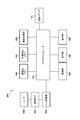
- FIG. 1A is a block diagram showing the configuration of the imaging device 204.
- 100 is a lens (shooting lens).
- a type of lens 100 a single focus lens or a zoom lens exists.
- the microcomputer 103 described later can obtain information from the lens 100 such as the focal length, the current zoom position, and the length of the lens barrel.
- the lens 100 can move the zoom position when zoom drive is instructed from the microcomputer 103 or the like.
- the imaging device 204 may be a so-called interchangeable lens camera or a lens-integrated camera.
- the imaging device 204 has a lens mount for attaching and detaching various lenses 100, communicates with the lens 100 being mounted via the lens mount, and various lens information such as specifications and current zoom position It is possible to get
- Reference numeral 101 denotes an imaging device. As the imaging device 101, a CCD, a CMOS sensor or the like is used. The imaging element 101 converts an object image formed by the lens 100 into an electrical signal.
- Reference numeral 102 denotes an A / D converter. The A / D converter 102 converts an analog output signal of the imaging element 101 into a digital signal.
- Reference numeral 103 denotes a microcomputer.
- the microcomputer 103 executes control of the entire imaging device 204, such as control of each component and data processing.
- the microcomputer 103 performs control in response to an operation instruction from the operation unit 109, generation and reproduction of an image to be displayed on the display unit 108, network control via the communication unit 107, and the like.
- the entire processing of the imaging device 204 is realized by the microcomputer 103, including communication processing in cooperation with the drone 205 described later, control for receiving the state of the drone 205, processing for controlling the drone 205, and the like.
- Ru The microcomputer 103 also handles communication control with the lens 100. Control regarding the lens 100 such as mounting / dismounting of the lens 100, acquisition of zoom position, acquisition of the shortest photographing distance, zoom control of the lens 100, etc. is also performed by the microcomputer 103.
- the volatile memory 104 is a volatile memory.
- the volatile memory 104 temporarily holds image data converted into a digital signal by the A / D converter 102.
- 105 is a non-volatile memory.
- the non-volatile memory 105 holds a control program of the imaging device 204 that the microcomputer 103 executes.
- the non-volatile memory 105 also stores setting values in the imaging device 204.
- Reference numeral 106 denotes an image processing unit.
- the image processing unit 106 performs image processing on the captured image.
- the image processing unit 106 also cooperates with the microcomputer 103 to generate a live view image for confirming the composition and focus at the time of shooting.
- Reference numeral 107 denotes a communication unit.
- the communication unit 107 is implemented by, for example, a technology such as a wireless LAN. With respect to communication technology, distinctions between wired connection and wireless connection need not be particularly considered.
- the cooperation method may be a method using a dedicated Software Development Kit (hereinafter referred to as SDK) or an API release method such as an HTTP-based Web API.
- SDK Software Development Kit
- API release method such as an HTTP-based Web API.
- control mechanism published by the imaging device 204 or the drone 205 may be used. Alternatively, control may be performed using a cooperation mechanism disclosed in both the imaging device 204 and the drone 205.
- the cooperation method is not particularly limited.
- Reference numeral 108 denotes a display unit.
- the display unit 108 is controlled by the microcomputer 103 to display a menu, display a reproduced image, and the like.
- the display unit 108 also displays a live view image.
- Reference numeral 109 denotes an operation unit.
- the operation unit 109 can perform an operation on the user interface displayed on the display unit 108. As an operation method of the operation unit 109, a key operation, a touch panel operation, or the like is assumed.
- Reference numeral 110 denotes a recording medium.
- the recording medium 110 is, for example, Compact Flash (registered trademark) (CF).
- CF Compact Flash
- the microcomputer 103 can write data of the volatile memory 104 to the recording medium 110 and can read data stored in the recording medium 110 to the volatile memory 104.
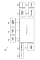
- FIG. 1B is a block diagram showing a configuration of a drone 205 (unmanned aircraft) which is an example of a mobile device.
- 111 is a propeller.
- 112 is a flight control unit.
- the flight control unit 112 performs flight control of the drone 205 in cooperation with the microcomputer 113.
- the flight control unit 112 performs processing to control the drone 205 not to fly, and control to acquire the length and height of the propeller. Further, the flight control unit 112 also performs control such that the drone 205 itself (or the entire flight system including the mounted imaging device 204) does not collide (touch) with an object such as a subject. Note that any existing technology can be used as the drone 205 collision avoidance algorithm.
- 113 is a microcomputer.
- the drone 205 is controlled by the microcomputer 113.
- the microcomputer 113 cooperates with other components to perform various processes.
- 114 is a volatile memory.
- Reference numeral 115 denotes a non-volatile memory.
- the non-volatile memory 115 holds a control program that the microcomputer 113 executes.
- An external device communication unit 116 is provided.
- the external device communication unit 116 communicates with the communication unit 107 of the imaging device 204 in order to realize cooperation between the drone 205 and the imaging device 204.
- the communication method is not particularly limited, and may be wired or wireless.
- the communication protocol is not particularly limited. As the contents of the communication, a command for controlling the drone 205, a notification regarding the state of the drone 205, a command for controlling the imaging device 204, information regarding the lens 100 mounted on the imaging device 204, and the like are assumed.
- An external device control unit 117 is provided. 118 is a gimbal.
- the imaging device 204 can be mounted on the drone 205 using the gimbal 118.
- the external device control unit 117 can control the angle of the imaging device 204 mounted on the gimbal 118 in cooperation with the microcomputer 113.
- Reference numeral 119 denotes a remote control communication unit.
- the drone 205 is controlled by a user with a remote control.
- the drone 205 may be a self-propelled drone that can fly with a flight path or the like set in advance.
- the microcomputer 113 receives a control command from the remote control via the remote control communication unit 119.
- Reference numeral 120 denotes a light emission control unit.
- Reference numeral 121 denotes a light emitting unit.
- the light emitting unit 121 is mounted on the drone 205 in order to make it possible for the user to see where the drone 205 is flying in view of night flight and the like.
- the light emission control unit 120 controls the light emission of the light emitting unit 121.
- the light emitting unit 121 includes, for example, an LED, but the type of the light emitting unit is not particularly limited.
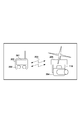
- FIG. 2 is a block diagram of the remote control system of the drone 205. As shown in FIG. As shown in FIG. 2, the imaging device 204 is supported by the gimbal 118 of the drone 205 and mounted on the drone 205.
- Reference numeral 200 denotes a remote control for remotely controlling the drone 205.
- the user can control the drone 205 by operating the remote control 200.
- the remote controller 200 is not limited to the remote controller prepared exclusively for the drone 205.
- at least one software for controlling the drone 205 may be installed on a mobile device such as a smartphone or a tablet device and used as the remote control 200.
- Reference numeral 201 denotes a display unit. Image data captured by the imaging device 204 mounted on the drone 205 can be displayed on the display unit 201 of the remote control 200. The user can check a still image to be photographed, an angle of view of a moving image, and the like while looking at the display unit 201. Further, when an error or the like occurs when the imaging device 204 and the drone 205 cooperate to provide a function, the drone 205 notifies the remote control 200 of the error, and the display unit 201 displays the notification.
- Reference numeral 202 denotes an operation unit.
- the user can control takeoff, landing, advancing, rotation, and the like of the drone 205 by operating the operation unit 202 of the remote control 200.
- the user can also control the imaging device 204 via the drone 205.
- the drone 205 and the imaging device 204 can communicate with each other. Therefore, for example, the user can control the lens 100 mounted on the imaging device 204 by operating the operation unit 202.
- the user can perform various controls on the drone 205 and the imaging device 204 using the remote control 200, and the types of possible controls are not particularly limited.
- Reference numeral 203 denotes communication between the remote control 200 and the remote control communication unit 119 of the drone 205.
- a remote control radio wave for controlling the drone 205 for example, a propo or the like is assumed. Since the drone 205 is assumed to fly at an altitude of several hundred meters, basically, communication by long distance wireless or wired is assumed.
- the communication method between the remote control 200 and the drone 205 is not particularly limited.
- a predetermined control device appropriately controls the imaging device 204 or the drone 205 in consideration of the influence of the imaging device 204 and the drone 205 on each other. More specifically, the control device controls the imaging device 204 or the drone 205 based on at least one of information on the lens 100 of the imaging device 204 (lens information) and information on the drone 205 (moving device information). .
- the details of the lens information and the moving device information and the details of the control executed by the control device are not particularly limited, five control examples will be described below with reference to FIGS. 3A to 3E.
- control device may be implemented by the microcomputer 103 or may be implemented by the microcomputer 113. That is, the control device may be included in the imaging device 204 or may be included in the drone 205. Alternatively, the control device may be a device separate from the imaging device 204 and the drone 205, which can communicate with the imaging device 204 and the drone 205. Alternatively, the control device may be implemented by a combination of a plurality of microcomputers (for example, microcomputer 103 and microcomputer 113).
- the control device When the control device is implemented by the microcomputer 103, the processing of each step in FIGS. 3A to 3E is realized by the microcomputer 103 executing the control program stored in the non-volatile memory 105 unless otherwise specified. Ru. When the control device is implemented by the microcomputer 113, the processing of each step in FIGS. 3A to 3E is realized by the microcomputer 113 executing the control program stored in the non-volatile memory 115 unless otherwise specified. Ru. When the control device is a device separate from the imaging device 204 and the drone 205, the control device includes a microcomputer and a non-volatile memory (not shown). In this case, the processing of each step in FIGS.
- 3A to 3E is realized by the microcomputer (not shown) executing the control program stored in the nonvolatile memory (not shown) unless otherwise specified.
- the control device is implemented by a combination of a plurality of microcomputers, the processing of each step in FIGS. 3A to 3E is realized by the plurality of microcomputers appropriately sharing the roles unless otherwise specified.
- the imaging device 204 and the drone 205 appropriately communicate information and control commands according to the implementation of the control device. For example, when the control device needs information on the imaging device 204, communication is not necessary if the control device is included in the imaging device 204, but if the control device is included in the drone 205, the imaging device 204. Sends the requested information to the drone 205. In addition, when at least a part of the control device is implemented by a device separate from the imaging device 204 and the drone 205, between the imaging device 204 and the drone 205 and the control device via a communication unit included in the separate device. The necessary information is communicated as appropriate. If the control device is not included in the drone 205, control of the drone 205 is performed by communicating control commands between the control device and the drone 205. Similarly, when the control device is not included in the imaging device 204, control of the imaging device 204 is performed by communicating control commands between the control device and the imaging device 204.
- Communication between devices may be performed via another device.
- the control device may transmit the control command to the imaging device 204 via the drone 205.
- the distance between the imaging device 204 and the subject may be less than the shortest photographing distance (the shortest subject distance that can be focused). In this case, the imaging device 204 can not focus on the subject, and there is a possibility that the subject can not be photographed properly.
- control for suppressing the occurrence of such a situation will be described.
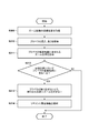
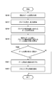
- FIG. 3A is a flowchart of a first control example executed by the control device in the control system including the control device, the imaging device 204, and the drone 205.
- the processing of this flowchart starts.
- a so-called live view image is transmitted from the drone 205 to the remote control 200, the flowchart may be started in response to a transmission request of the live view image.
- the control device acquires information indicating the current distance (the current object distance) between the imaging device 204 and the predetermined object.
- the subject distance can be acquired using the function of the imaging device 204.
- the microcomputer 103 acquires the subject distance from the distance measuring unit (not shown) in accordance with an instruction from the control device, and provides the subject distance to the control device.
- the control device obtains the current zoom position of the lens 100.
- the current zoom position is acquired from the lens 100 by cooperation of the lens 100 and the microcomputer 103.
- the control device acquires the shortest imaging distance based on the current zoom position.
- the control device determines whether the current subject distance acquired in S300 is less than the shortest photographing distance acquired in S303 (less than the shortest object distance). If (subject distance) ⁇ (minimum shooting distance), the process proceeds to step S305. If not, the process of this flowchart ends.
- the condition that (subject distance) ⁇ (shortest shooting distance) means that the drone 205 is too close to the subject, so that it is in a situation where focusing is not achieved. In order to avoid such a situation, the control device calculates the distance for moving the drone 205 in S305. Specifically, the control device subtracts the subject distance obtained in S300 from the shortest shooting distance obtained in S303.
- step S306 the control device controls the drone 205 to move in a direction away from the subject by the distance calculated in step S305. That is, the control device controls the drone 205 to move so that the subject distance is equal to or more than the shortest imaging distance (equal to or more than the shortest object distance).
- step S307 the drone 205 moves away from the subject according to the control by the control device in step S306.
- the control device controls the drone 205 so that (subject distance) ⁇ (shortest shooting distance). This makes it possible to suppress the occurrence of a situation where it is impossible to focus on the subject.
- the control device may notify the remote control 200.
- the remote controller 200 that has received the notification may cause the display unit 201 to display a guidance such as, for example, “The drone is closer to the subject than the shortest shooting distance. The drone will be retracted.”
- the control device only notifies the remote control 200 without controlling the flight of the drone 205, and the remote control 200 gives guidance such as "The object is closer than the shortest shooting distance. Please retreat the drone.” It may be displayed on the display unit 201.
- Second control example When the focal length of the lens 100 is short (for example, when the zoom position of the wide-angle lens is on the Wide side), a predetermined portion (for example, the propeller 111) of the drone 205 may be reflected in the captured image.
- a predetermined portion for example, the propeller 111 of the drone 205 may be reflected in the captured image.
- control for suppressing the occurrence of such a situation will be described.
- FIG. 3B is a flowchart of a second control example executed by the control device in the control system including the control device, the imaging device 204, and the drone 205.
- the control device in the control system including the control device, the imaging device 204, and the drone 205.
- step S309 the control device acquires a target position (a zoom position of a movement target in zoom control for moving the zoom position) corresponding to the change request of the zoom position.
- the control device acquires information (height and length) indicating the position of the propeller 111 of the drone 205.
- the flight control unit 112 and the microcomputer 113 of the drone 205 are used for this acquisition process.
- the control device calculates a zoom position in which the propeller 111 is included in the imaging range, based on the height and the length of the propeller 111 acquired in S310.
- the control device may calculate the entire zoom position range in which the propeller 111 is included in the imaging range, or may calculate the zoom position on the most Tele side in which the propeller 111 is included in the imaging range.
- the control device determines whether the propeller 111 is included in the imaging range when the zoom position of the lens 100 moves to the target position based on the target position acquired in S309 and the zoom position acquired in S311. judge. If the propeller 111 is included in the imaging range, the process proceeds to S313. If not, the process of this flowchart ends.
- the control device performs zoom control of the lens 100 so that the propeller 111 does not move to the zoom position included in the imaging range.
- the control device stops the movement of the zoom position at the boundary of this range so that the zoom position of the lens 100 does not fall within the zoom position range in which the propeller 111 is included in the imaging range.
- the control device notifies the remote control 200 of warning information indicating that the zoom control has been performed so that the propeller 111 does not move to the zoom position included in the imaging range.
- the remote controller 200 displays a warning on the display unit 201.
- the control device when the predetermined portion (for example, the propeller 111) of the drone 205 is included in the imaging range at the zoom control target position, the control device does not move the predetermined portion to the zoom position included in the imaging range The zoom control of the lens 100 is performed. As a result, it is possible to suppress the occurrence of a situation in which a predetermined part (for example, the propeller 111) of the drone 205 is reflected in the captured image.
- control device may not perform zoom control, but may only notify the remote control 200.
- zoom control may not perform zoom control, but may only notify the remote control 200.
- remote control 200 may not notify the remote control 200.
- the third control example is a modification of the second control example.
- control for suppressing the occurrence of a situation in which a predetermined portion (for example, the propeller 111) of the drone 205 is reflected in a captured image will be described.
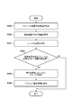
- FIG. 3C is a flowchart of a third control example executed by the control device in the control system including the control device, the imaging device 204, and the drone 205.
- the control device acquires the current zoom position of the lens 100 by the same processing as S302 (FIG. 3A).
- the control device acquires information (height and length) indicating the position of the propeller 111 of the drone 205 by the same processing as S310 (FIG. 3B).
- the control device calculates the zoom position in which the propeller 111 is included in the imaging range by the same processing as S311 (FIG. 3B).
- the control device calculates the difference between the current zoom position and the zoom position at which the propeller 111 is included in the imaging range.
- the control device determines whether the difference calculated in S319 is less than the threshold.
- the process proceeds to S321, otherwise the process of this flowchart ends Do.
- the control device slows down the speed of zoom control. That is, the control device controls the zoom position of the lens 100 to move at a slower speed than in the case where the current zoom position is separated from the zoom position in which the propeller 111 is included in the imaging range.
- the control device notifies the remote control 200 of warning information indicating that the speed of zoom control has been reduced. In response to the notification, the remote controller 200 displays a warning on the display unit 201.
- the control device when the zoom control in the Wide direction is performed, the control device is a difference between the current zoom position and the zoom position where a predetermined portion of the drone 205 (for example, the propeller 111) is included in the imaging range. Is less than the threshold, the speed of the zoom control is reduced. As a result, it is possible to suppress the occurrence of a situation in which a predetermined part (for example, the propeller 111) of the drone 205 is reflected in the captured image.
- a predetermined portion of the drone 205 for example, the propeller 111
- ⁇ fourth control example In order for the drone 205 to effectively avoid collision with an obstacle according to the aforementioned collision avoidance algorithm, the size of the entire flight system is required, including the size of the imaging device 204 mounted on the drone 205. . However, if the length of the lens barrel of the lens 100 changes due to zoom control, the size of the flight system changes. As a result, effective collision avoidance may not be possible. In the fourth control example, control for suppressing the occurrence of such a situation will be described.
- FIG. 3D is a flowchart of a fourth control example executed by the control device in the control system including the control device, the imaging device 204, and the drone 205.
- the control device in the control system including the control device, the imaging device 204, and the drone 205.
- the control device changes the zoom position of the lens 100 in accordance with the zoom position change request.
- the control device acquires the current zoom position of the lens 100 by the same processing as S302 (FIG. 3A).
- the control device acquires the length of the lens barrel of the lens 100 corresponding to the zoom position acquired in S324.
- the lens 100 and the microcomputer 103 cooperate to acquire the length of the lens barrel from the lens 100.
- the length of the lens barrel of the lens 100 may be stored in advance in the non-volatile memory 105 for each zoom position.
- the control device notifies the drone 205 of the length of the lens barrel acquired in S325, and controls the drone 205 to update the collision avoidance algorithm (or change the parameter) based on the length of the lens barrel. .
- the control device updates the collision avoidance algorithm of the drone 205 based on the length of the lens barrel. More specifically, the control device controls the movement (flight) of the drone 205 so that at least the lens barrel does not contact an object (obstacle) by updating the collision avoidance algorithm based on the length of the lens barrel. As a result, even when the length of the lens barrel of the lens 100 changes, the drone 205 can effectively avoid a collision with an obstacle.
- control example can be applied not only to the collision avoidance algorithm but also to various flight control algorithms such as control of turning, rotation and flight speed.
- various flight control algorithms such as control of turning, rotation and flight speed.
- the control device updates the flight control algorithm (or changes parameters) based on the length and weight of the lens barrel.
- ⁇ fifth control example A case is considered where the total of the weight of the lens 100 and the weight of the main body of the imaging device 204 (the weight of the imaging device 204 excluding the lens 100) exceeds the mountable maximum weight of the drone 205 (mountable weight). In this case, when the drone 205 starts to fly, the drone 205 may not be able to fly normally. In particular, when the imaging device 204 has a configuration in which the lens 100 can be replaced, the total weight changes depending on the type of the lens 100 mounted. As a result, the risk of causing the drone 205 to fly without the user being aware that the mounted weight exceeds the mountable weight is increased.
- the fifth control example describes control for suppressing the occurrence of such a situation.
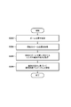
- FIG. 3E is a flowchart of a fifth control example executed by the control device in the control system including the control device, the imaging device 204, and the drone 205.
- the control device in the control system including the control device, the imaging device 204, and the drone 205.
- the control device acquires the loadable weight of the drone 205.
- the mountable weight is stored, for example, in the non-volatile memory 115 of the drone 205.
- the control device acquires the weight of the main body of the imaging device 204.
- the weight of the main body of the imaging device 204 is stored, for example, in the non-volatile memory 105 of the imaging device 204.
- the control device obtains the weight of the lens 100.
- the weight for each type of lens may be stored in advance in the non-volatile memory 105.
- the control device determines whether the total of the weight of the imaging device 204 main body and the weight of the lens 100 exceeds the mountable weight. If the total of the weight of the imaging device 204 and the weight of the lens 100 exceeds the mountable weight, the process proceeds to S333. If not, the process of this flowchart ends.
- the control device controls the drone 205 not to start flight.
- the control device notifies the remote control 200 of warning information indicating that the drone 205 has been controlled not to start flight. In response to the notification, the remote controller 200 displays a warning on the display unit 201.
- control device controls the drone 205 not to start flight when the total weight of the main body of the imaging device 204 and the weight of the lens 100 exceeds the mountable weight. This makes it possible to reduce the possibility that the drone 205 can not fly normally.
- the fifth control example can be modified to control the travel of the drone 205.
- the control device controls the drone 205 not to start traveling. More generally, the controller can control any type of movement, including flight and travel.
- the control device controls the drone 205 based on the information on the lens 100, the information on the lens 100, and the drone 205. Control the lens 100 on the basis of the information on. Therefore, according to the present embodiment, in the situation where the imaging device 204 is mounted on the drone 205, the imaging device 204 or the drone 205 can be more appropriately controlled.
- the mobile device of this embodiment is not limited to this, and it is not essential to fly.
- the moving device may be, for example, a vehicle traveling on the ground.
- control examples 1 to 5 as a trigger for performing control, an imaging request, a zoom position change request, and a flight start request of the drone 205 have been exemplified.
- various controls can be realized by notifying information in advance as well as the trigger. Therefore, in all of the control examples 1 to 5, various control can be realized by notifying the drone 205 side of the information of the imaging device 204 in advance or notifying the imaging device 204 of the information of the drone 205 in advance. It is.
- Embodiments The present invention supplies a program that implements one or more functions of the above-described embodiments to a system or apparatus via a network or storage medium, and one or more processors in a computer of the system or apparatus read and execute the program. Can also be realized. It can also be implemented by a circuit (eg, an ASIC) that implements one or more functions.
- a circuit eg, an ASIC
Landscapes
- Engineering & Computer Science (AREA)
- Physics & Mathematics (AREA)
- Multimedia (AREA)
- Signal Processing (AREA)
- General Physics & Mathematics (AREA)
- Aviation & Aerospace Engineering (AREA)
- Mechanical Engineering (AREA)
- Remote Sensing (AREA)
- Optics & Photonics (AREA)
- Chemical & Material Sciences (AREA)
- Combustion & Propulsion (AREA)
- Radar, Positioning & Navigation (AREA)
- Automation & Control Theory (AREA)
- General Engineering & Computer Science (AREA)
- Studio Devices (AREA)
- Lens Barrels (AREA)
- Control Of Position, Course, Altitude, Or Attitude Of Moving Bodies (AREA)
Priority Applications (4)
| Application Number | Priority Date | Filing Date | Title |
|---|---|---|---|
| EP18848454.7A EP3687159B1 (en) | 2017-08-23 | 2018-07-04 | Control device, control system, control method, program and recording medium |
| KR1020207006659A KR102340617B1 (ko) | 2017-08-23 | 2018-07-04 | 제어장치, 제어 시스템, 제어 방법, 프로그램, 및 기억 매체 |
| CN201880054103.2A CN111034172B (zh) | 2017-08-23 | 2018-07-04 | 控制设备、控制系统、控制方法及存储介质 |
| US16/748,485 US11310416B2 (en) | 2017-08-23 | 2020-01-21 | Control device, control system, control method, and storage medium |
Applications Claiming Priority (2)
| Application Number | Priority Date | Filing Date | Title |
|---|---|---|---|
| JP2017-160529 | 2017-08-23 | ||
| JP2017160529A JP7057637B2 (ja) | 2017-08-23 | 2017-08-23 | 制御装置、制御システム、制御方法、プログラム、及び記憶媒体 |
Related Child Applications (1)
| Application Number | Title | Priority Date | Filing Date |
|---|---|---|---|
| US16/748,485 Continuation US11310416B2 (en) | 2017-08-23 | 2020-01-21 | Control device, control system, control method, and storage medium |
Publications (1)
| Publication Number | Publication Date |
|---|---|
| WO2019039099A1 true WO2019039099A1 (ja) | 2019-02-28 |
Family
ID=65440031
Family Applications (1)
| Application Number | Title | Priority Date | Filing Date |
|---|---|---|---|
| PCT/JP2018/025341 Ceased WO2019039099A1 (ja) | 2017-08-23 | 2018-07-04 | 制御装置、制御システム、制御方法、プログラム、及び記憶媒体 |
Country Status (6)
| Country | Link |
|---|---|
| US (1) | US11310416B2 (enExample) |
| EP (1) | EP3687159B1 (enExample) |
| JP (1) | JP7057637B2 (enExample) |
| KR (1) | KR102340617B1 (enExample) |
| CN (1) | CN111034172B (enExample) |
| WO (1) | WO2019039099A1 (enExample) |
Cited By (3)
| Publication number | Priority date | Publication date | Assignee | Title |
|---|---|---|---|---|
| JPWO2021024627A1 (enExample) * | 2019-08-08 | 2021-02-11 | ||
| CN114849234A (zh) * | 2022-06-01 | 2022-08-05 | 网易(杭州)网络有限公司 | 虚拟镜头控制方法、装置、存储介质和电子设备 |
| US20230058405A1 (en) * | 2021-08-20 | 2023-02-23 | Sony Group Corporation | Unmanned aerial vehicle (uav) swarm control |
Families Citing this family (10)
| Publication number | Priority date | Publication date | Assignee | Title |
|---|---|---|---|---|
| WO2020107372A1 (zh) * | 2018-11-30 | 2020-06-04 | 深圳市大疆创新科技有限公司 | 拍摄设备的控制方法、装置、设备及存储介质 |
| JP6878738B1 (ja) * | 2020-02-12 | 2021-06-02 | エスゼット ディージェイアイ テクノロジー カンパニー リミテッドSz Dji Technology Co.,Ltd | 制御装置、撮像システム、移動体、制御方法、及びプログラム |
| WO2022020238A1 (en) * | 2020-07-20 | 2022-01-27 | Canon U.S.A., Inc. | Control system for an unmanned autonomous vehicle |
| JP7104114B2 (ja) | 2020-08-21 | 2022-07-20 | 楽天グループ株式会社 | 飛行体、システム、及び、方法 |
| CN112401752B (zh) * | 2020-11-04 | 2022-05-17 | 北京石头创新科技有限公司 | 一种检测未知障碍物的方法、装置、介质和电子设备 |
| WO2022141348A1 (en) | 2020-12-31 | 2022-07-07 | SZ DJI Technology Co., Ltd. | Systems, devices, and methods supporting multiple photography modes with a control device |
| CN118450230A (zh) * | 2020-12-31 | 2024-08-06 | 深圳市大疆创新科技有限公司 | 拍摄设备、控制设备、遥控设备、移动控制系统和可穿戴设备 |
| JP7696769B2 (ja) | 2021-06-29 | 2025-06-23 | キヤノン株式会社 | 無人飛行装置および無人飛行装置の制御方法 |
| JP7776972B2 (ja) | 2021-11-25 | 2025-11-27 | キヤノン株式会社 | 撮像装置、制御方法およびプログラム |
| JP2024033521A (ja) | 2022-08-30 | 2024-03-13 | キヤノン株式会社 | 撮像システム及びその制御方法とプログラム |
Citations (7)
| Publication number | Priority date | Publication date | Assignee | Title |
|---|---|---|---|---|
| JP2016111414A (ja) * | 2014-12-03 | 2016-06-20 | コニカミノルタ株式会社 | 飛行体の位置検出システム及び飛行体 |
| JP2016220004A (ja) | 2015-05-19 | 2016-12-22 | オリンパス株式会社 | 撮像装置 |
| JP2016225874A (ja) | 2015-06-01 | 2016-12-28 | 日本電信電話株式会社 | 表示画像ズーム端末、表示画像ズーム方法及び表示画像ズームプログラム |
| JP2017503226A (ja) * | 2014-07-30 | 2017-01-26 | エスゼット ディージェイアイ テクノロジー カンパニー リミテッドSz Dji Technology Co.,Ltd | 目標追跡システム、デバイスおよび方法 |
| JP6103672B1 (ja) * | 2016-07-20 | 2017-03-29 | エスゼット ディージェイアイ テクノロジー カンパニー リミテッドSz Dji Technology Co.,Ltd | 制御装置、撮像装置、移動体、制御方法、及びプログラム |
| JP6146520B1 (ja) * | 2016-07-12 | 2017-06-14 | エスゼット ディージェイアイ テクノロジー カンパニー リミテッドSz Dji Technology Co., Ltd | 光学装置、移動体、保持位置調整方法、及びプログラム |
| JP2017112440A (ja) * | 2015-12-15 | 2017-06-22 | キヤノン株式会社 | 撮像システムおよびその制御方法、移動撮像装置、通信装置 |
Family Cites Families (21)
| Publication number | Priority date | Publication date | Assignee | Title |
|---|---|---|---|---|
| FI55682C (fi) | 1977-09-06 | 1979-09-10 | Viljanmaa Antti | Spaennanordning foer skinn |
| JPS56159165A (en) | 1980-05-14 | 1981-12-08 | Hiraoka Shokusen | Resin coated cloth silk having large tear strength |
| US5305038A (en) * | 1991-07-30 | 1994-04-19 | Asahi Kogaku Kogyo Kabushiki Kaisha | Zoom lens camera |
| JP2004288100A (ja) * | 2003-03-25 | 2004-10-14 | Minolta Co Ltd | 撮像装置及び移動体カメラ |
| JP2012023546A (ja) * | 2010-07-14 | 2012-02-02 | Jvc Kenwood Corp | 制御装置、立体映像撮像装置、および制御方法 |
| CN102809969A (zh) * | 2011-06-03 | 2012-12-05 | 鸿富锦精密工业(深圳)有限公司 | 无人飞行载具控制系统及方法 |
| JP6003530B2 (ja) * | 2012-10-25 | 2016-10-05 | リコーイメージング株式会社 | ズームレンズ系 |
| JP5561843B1 (ja) * | 2013-01-07 | 2014-07-30 | 株式会社amuse oneself | 制御装置、測量システム、プログラム及び記録媒体並びに計測方法 |
| CN103426282A (zh) * | 2013-07-31 | 2013-12-04 | 深圳市大疆创新科技有限公司 | 遥控方法及终端 |
| US8903568B1 (en) | 2013-07-31 | 2014-12-02 | SZ DJI Technology Co., Ltd | Remote control method and terminal |
| US11140326B2 (en) * | 2015-05-22 | 2021-10-05 | The United States Of America, As Represented By The Secretary Of The Navy | Aerial video based point, distance, and velocity real-time measurement system |
| JP2017034444A (ja) * | 2015-07-31 | 2017-02-09 | オリンパス株式会社 | 撮像装置および撮像方法 |
| FR3041134B1 (fr) * | 2015-09-10 | 2017-09-29 | Parrot | Drone avec camera a visee frontale dont les parametres de controle, notamment l'autoexposition, sont rendus independant de l'attitude. |
| CN119645078A (zh) * | 2015-09-15 | 2025-03-18 | 深圳市大疆创新科技有限公司 | 控制可移动物体跟踪目标的系统和方法 |
| JP6596745B2 (ja) * | 2015-10-20 | 2019-10-30 | エスゼット ディージェイアイ テクノロジー カンパニー リミテッド | 対象物体を撮像するシステム |
| JP6318455B1 (ja) * | 2016-06-13 | 2018-05-09 | エスゼット ディージェイアイ テクノロジー カンパニー リミテッドSz Dji Technology Co.,Ltd | 制御装置、撮像装置、移動体、制御方法及びプログラム |
| JP6500849B2 (ja) * | 2016-06-23 | 2019-04-17 | カシオ計算機株式会社 | 撮像装置、撮像方法及びプログラム |
| WO2018010095A1 (en) * | 2016-07-12 | 2018-01-18 | SZ DJI Technology Co., Ltd. | System for balancing center of gravity of a zoom lens |
| CN109479086B (zh) * | 2016-07-20 | 2021-08-10 | 深圳市大疆创新科技有限公司 | 相对于物体变焦的方法和设备 |
| CN107079106B (zh) * | 2016-09-26 | 2020-11-13 | 深圳市大疆创新科技有限公司 | 对焦方法和装置、图像拍摄方法和装置及摄像系统 |
| WO2018098678A1 (zh) | 2016-11-30 | 2018-06-07 | 深圳市大疆创新科技有限公司 | 飞行器的控制方法、装置和设备以及飞行器 |
-
2017
- 2017-08-23 JP JP2017160529A patent/JP7057637B2/ja active Active
-
2018
- 2018-07-04 WO PCT/JP2018/025341 patent/WO2019039099A1/ja not_active Ceased
- 2018-07-04 KR KR1020207006659A patent/KR102340617B1/ko active Active
- 2018-07-04 EP EP18848454.7A patent/EP3687159B1/en active Active
- 2018-07-04 CN CN201880054103.2A patent/CN111034172B/zh active Active
-
2020
- 2020-01-21 US US16/748,485 patent/US11310416B2/en active Active
Patent Citations (7)
| Publication number | Priority date | Publication date | Assignee | Title |
|---|---|---|---|---|
| JP2017503226A (ja) * | 2014-07-30 | 2017-01-26 | エスゼット ディージェイアイ テクノロジー カンパニー リミテッドSz Dji Technology Co.,Ltd | 目標追跡システム、デバイスおよび方法 |
| JP2016111414A (ja) * | 2014-12-03 | 2016-06-20 | コニカミノルタ株式会社 | 飛行体の位置検出システム及び飛行体 |
| JP2016220004A (ja) | 2015-05-19 | 2016-12-22 | オリンパス株式会社 | 撮像装置 |
| JP2016225874A (ja) | 2015-06-01 | 2016-12-28 | 日本電信電話株式会社 | 表示画像ズーム端末、表示画像ズーム方法及び表示画像ズームプログラム |
| JP2017112440A (ja) * | 2015-12-15 | 2017-06-22 | キヤノン株式会社 | 撮像システムおよびその制御方法、移動撮像装置、通信装置 |
| JP6146520B1 (ja) * | 2016-07-12 | 2017-06-14 | エスゼット ディージェイアイ テクノロジー カンパニー リミテッドSz Dji Technology Co., Ltd | 光学装置、移動体、保持位置調整方法、及びプログラム |
| JP6103672B1 (ja) * | 2016-07-20 | 2017-03-29 | エスゼット ディージェイアイ テクノロジー カンパニー リミテッドSz Dji Technology Co.,Ltd | 制御装置、撮像装置、移動体、制御方法、及びプログラム |
Non-Patent Citations (1)
| Title |
|---|
| See also references of EP3687159A4 |
Cited By (5)
| Publication number | Priority date | Publication date | Assignee | Title |
|---|---|---|---|---|
| JPWO2021024627A1 (enExample) * | 2019-08-08 | 2021-02-11 | ||
| WO2021024627A1 (ja) * | 2019-08-08 | 2021-02-11 | ソニー株式会社 | 情報処理装置、移動体、情報処理システム、情報処理方法及びプログラム |
| US12055396B2 (en) | 2019-08-08 | 2024-08-06 | Sony Group Corporation | Information processing apparatus, moving body, information processing system, information processing method, and program |
| US20230058405A1 (en) * | 2021-08-20 | 2023-02-23 | Sony Group Corporation | Unmanned aerial vehicle (uav) swarm control |
| CN114849234A (zh) * | 2022-06-01 | 2022-08-05 | 网易(杭州)网络有限公司 | 虚拟镜头控制方法、装置、存储介质和电子设备 |
Also Published As
| Publication number | Publication date |
|---|---|
| CN111034172B (zh) | 2021-11-16 |
| EP3687159B1 (en) | 2023-05-10 |
| US11310416B2 (en) | 2022-04-19 |
| KR102340617B1 (ko) | 2021-12-20 |
| JP7057637B2 (ja) | 2022-04-20 |
| KR20200039725A (ko) | 2020-04-16 |
| CN111034172A (zh) | 2020-04-17 |
| EP3687159A4 (en) | 2021-08-18 |
| EP3687159A1 (en) | 2020-07-29 |
| JP2019041185A (ja) | 2019-03-14 |
| US20200162667A1 (en) | 2020-05-21 |
Similar Documents
| Publication | Publication Date | Title |
|---|---|---|
| WO2019039099A1 (ja) | 制御装置、制御システム、制御方法、プログラム、及び記憶媒体 | |
| JP6239993B2 (ja) | 撮像装置、表示装置、及び制御方法 | |
| JP6639979B2 (ja) | 撮影機器及び撮影用移動体 | |
| JP6697340B2 (ja) | 撮影機器、移動撮影装置、撮影用移動体及び移動体用撮影制御装置 | |
| WO2018163571A1 (ja) | 情報処理装置、情報処理方法および情報処理プログラム | |
| CN107431749B (zh) | 一种跟焦器控制方法和装置及系统 | |
| JP6281720B2 (ja) | 撮像システム | |
| WO2022151473A1 (zh) | 拍摄控制方法、拍摄控制装置及云台组件 | |
| JP6677684B2 (ja) | 映像配信システム | |
| KR101884125B1 (ko) | 셀피용 촬영 시스템 및 이를 이용한 촬영 방법 | |
| JP2017112440A (ja) | 撮像システムおよびその制御方法、移動撮像装置、通信装置 | |
| US9007515B2 (en) | Lens-interchangeable camera system, lens data transmission method and lens data acquisition program | |
| JP2020050261A (ja) | 情報処理装置、飛行制御指示方法、プログラム、及び記録媒体 | |
| US12063435B2 (en) | Image capturing apparatus, control method, and storage medium | |
| JP6136189B2 (ja) | 補助撮像装置および主撮像装置 | |
| JP6080825B2 (ja) | 撮像装置及びその制御方法 | |
| JP7580943B2 (ja) | 撮像装置、その制御方法およびプログラム | |
| JP2018107648A (ja) | 情報処理装置、及びその制御方法、プログラム | |
| JP2024033521A (ja) | 撮像システム及びその制御方法とプログラム | |
| JP2024031561A (ja) | 撮像装置、撮像装置の制御方法およびプログラム | |
| JP6335478B2 (ja) | レンズ装置及びそれを有する撮影装置 | |
| JP2014164206A (ja) | 撮像装置およびその制御方法、プログラム、記憶媒体 | |
| JP2018113545A (ja) | 操作制御方法、移動撮影装置、コントローラ、及びプログラム | |
| JP2019175476A (ja) | 情報処理装置、及びその制御方法、プログラム | |
| JP2021086119A (ja) | レンズ装置および撮像装置 |
Legal Events
| Date | Code | Title | Description |
|---|---|---|---|
| 121 | Ep: the epo has been informed by wipo that ep was designated in this application |
Ref document number: 18848454 Country of ref document: EP Kind code of ref document: A1 |
|
| NENP | Non-entry into the national phase |
Ref country code: DE |
|
| ENP | Entry into the national phase |
Ref document number: 20207006659 Country of ref document: KR Kind code of ref document: A |
|
| ENP | Entry into the national phase |
Ref document number: 2018848454 Country of ref document: EP Effective date: 20200323 |