EP3687159B1 - Control device, control system, control method, program and recording medium - Google Patents
Control device, control system, control method, program and recording medium Download PDFInfo
- Publication number
- EP3687159B1 EP3687159B1 EP18848454.7A EP18848454A EP3687159B1 EP 3687159 B1 EP3687159 B1 EP 3687159B1 EP 18848454 A EP18848454 A EP 18848454A EP 3687159 B1 EP3687159 B1 EP 3687159B1
- Authority
- EP
- European Patent Office
- Prior art keywords
- lens
- zoom
- control
- image capturing
- moving apparatus
- Prior art date
- Legal status (The legal status is an assumption and is not a legal conclusion. Google has not performed a legal analysis and makes no representation as to the accuracy of the status listed.)
- Active
Links
Images


Classifications
-
- G—PHYSICS
- G02—OPTICS
- G02B—OPTICAL ELEMENTS, SYSTEMS OR APPARATUS
- G02B7/00—Mountings, adjusting means, or light-tight connections, for optical elements
- G02B7/02—Mountings, adjusting means, or light-tight connections, for optical elements for lenses
- G02B7/04—Mountings, adjusting means, or light-tight connections, for optical elements for lenses with mechanism for focusing or varying magnification
- G02B7/10—Mountings, adjusting means, or light-tight connections, for optical elements for lenses with mechanism for focusing or varying magnification by relative axial movement of several lenses, e.g. of varifocal objective lens
- G02B7/102—Mountings, adjusting means, or light-tight connections, for optical elements for lenses with mechanism for focusing or varying magnification by relative axial movement of several lenses, e.g. of varifocal objective lens controlled by a microcomputer
-
- H—ELECTRICITY
- H04—ELECTRIC COMMUNICATION TECHNIQUE
- H04N—PICTORIAL COMMUNICATION, e.g. TELEVISION
- H04N23/00—Cameras or camera modules comprising electronic image sensors; Control thereof
- H04N23/60—Control of cameras or camera modules
- H04N23/665—Control of cameras or camera modules involving internal camera communication with the image sensor, e.g. synchronising or multiplexing SSIS control signals
-
- G—PHYSICS
- G05—CONTROLLING; REGULATING
- G05D—SYSTEMS FOR CONTROLLING OR REGULATING NON-ELECTRIC VARIABLES
- G05D1/00—Control of position, course, altitude or attitude of land, water, air or space vehicles, e.g. using automatic pilots
- G05D1/20—Control system inputs
- G05D1/22—Command input arrangements
- G05D1/221—Remote-control arrangements
-
- B—PERFORMING OPERATIONS; TRANSPORTING
- B64—AIRCRAFT; AVIATION; COSMONAUTICS
- B64C—AEROPLANES; HELICOPTERS
- B64C39/00—Aircraft not otherwise provided for
- B64C39/02—Aircraft not otherwise provided for characterised by special use
- B64C39/024—Aircraft not otherwise provided for characterised by special use of the remote controlled vehicle type, i.e. RPV
-
- B—PERFORMING OPERATIONS; TRANSPORTING
- B64—AIRCRAFT; AVIATION; COSMONAUTICS
- B64D—EQUIPMENT FOR FITTING IN OR TO AIRCRAFT; FLIGHT SUITS; PARACHUTES; ARRANGEMENT OR MOUNTING OF POWER PLANTS OR PROPULSION TRANSMISSIONS IN AIRCRAFT
- B64D47/00—Equipment not otherwise provided for
- B64D47/08—Arrangements of cameras
-
- B—PERFORMING OPERATIONS; TRANSPORTING
- B64—AIRCRAFT; AVIATION; COSMONAUTICS
- B64U—UNMANNED AERIAL VEHICLES [UAV]; EQUIPMENT THEREFOR
- B64U10/00—Type of UAV
- B64U10/10—Rotorcrafts
-
- B—PERFORMING OPERATIONS; TRANSPORTING
- B64—AIRCRAFT; AVIATION; COSMONAUTICS
- B64U—UNMANNED AERIAL VEHICLES [UAV]; EQUIPMENT THEREFOR
- B64U30/00—Means for producing lift; Empennages; Arrangements thereof
- B64U30/20—Rotors; Rotor supports
-
- B—PERFORMING OPERATIONS; TRANSPORTING
- B64—AIRCRAFT; AVIATION; COSMONAUTICS
- B64U—UNMANNED AERIAL VEHICLES [UAV]; EQUIPMENT THEREFOR
- B64U50/00—Propulsion; Power supply
- B64U50/10—Propulsion
- B64U50/13—Propulsion using external fans or propellers
-
- G—PHYSICS
- G02—OPTICS
- G02B—OPTICAL ELEMENTS, SYSTEMS OR APPARATUS
- G02B7/00—Mountings, adjusting means, or light-tight connections, for optical elements
- G02B7/02—Mountings, adjusting means, or light-tight connections, for optical elements for lenses
- G02B7/04—Mountings, adjusting means, or light-tight connections, for optical elements for lenses with mechanism for focusing or varying magnification
-
- G—PHYSICS
- G03—PHOTOGRAPHY; CINEMATOGRAPHY; ANALOGOUS TECHNIQUES USING WAVES OTHER THAN OPTICAL WAVES; ELECTROGRAPHY; HOLOGRAPHY
- G03B—APPARATUS OR ARRANGEMENTS FOR TAKING PHOTOGRAPHS OR FOR PROJECTING OR VIEWING THEM; APPARATUS OR ARRANGEMENTS EMPLOYING ANALOGOUS TECHNIQUES USING WAVES OTHER THAN OPTICAL WAVES; ACCESSORIES THEREFOR
- G03B15/00—Special procedures for taking photographs; Apparatus therefor
- G03B15/006—Apparatus mounted on flying objects
-
- G—PHYSICS
- G03—PHOTOGRAPHY; CINEMATOGRAPHY; ANALOGOUS TECHNIQUES USING WAVES OTHER THAN OPTICAL WAVES; ELECTROGRAPHY; HOLOGRAPHY
- G03B—APPARATUS OR ARRANGEMENTS FOR TAKING PHOTOGRAPHS OR FOR PROJECTING OR VIEWING THEM; APPARATUS OR ARRANGEMENTS EMPLOYING ANALOGOUS TECHNIQUES USING WAVES OTHER THAN OPTICAL WAVES; ACCESSORIES THEREFOR
- G03B5/00—Adjustment of optical system relative to image or object surface other than for focusing
-
- H—ELECTRICITY
- H04—ELECTRIC COMMUNICATION TECHNIQUE
- H04N—PICTORIAL COMMUNICATION, e.g. TELEVISION
- H04N23/00—Cameras or camera modules comprising electronic image sensors; Control thereof
- H04N23/60—Control of cameras or camera modules
- H04N23/63—Control of cameras or camera modules by using electronic viewfinders
- H04N23/633—Control of cameras or camera modules by using electronic viewfinders for displaying additional information relating to control or operation of the camera
- H04N23/634—Warning indications
-
- H—ELECTRICITY
- H04—ELECTRIC COMMUNICATION TECHNIQUE
- H04N—PICTORIAL COMMUNICATION, e.g. TELEVISION
- H04N23/00—Cameras or camera modules comprising electronic image sensors; Control thereof
- H04N23/60—Control of cameras or camera modules
- H04N23/66—Remote control of cameras or camera parts, e.g. by remote control devices
- H04N23/661—Transmitting camera control signals through networks, e.g. control via the Internet
-
- H—ELECTRICITY
- H04—ELECTRIC COMMUNICATION TECHNIQUE
- H04N—PICTORIAL COMMUNICATION, e.g. TELEVISION
- H04N23/00—Cameras or camera modules comprising electronic image sensors; Control thereof
- H04N23/60—Control of cameras or camera modules
- H04N23/69—Control of means for changing angle of the field of view, e.g. optical zoom objectives or electronic zooming
-
- H—ELECTRICITY
- H04—ELECTRIC COMMUNICATION TECHNIQUE
- H04N—PICTORIAL COMMUNICATION, e.g. TELEVISION
- H04N23/00—Cameras or camera modules comprising electronic image sensors; Control thereof
- H04N23/60—Control of cameras or camera modules
- H04N23/695—Control of camera direction for changing a field of view, e.g. pan, tilt or based on tracking of objects
-
- B—PERFORMING OPERATIONS; TRANSPORTING
- B64—AIRCRAFT; AVIATION; COSMONAUTICS
- B64U—UNMANNED AERIAL VEHICLES [UAV]; EQUIPMENT THEREFOR
- B64U2101/00—UAVs specially adapted for particular uses or applications
- B64U2101/30—UAVs specially adapted for particular uses or applications for imaging, photography or videography
-
- B—PERFORMING OPERATIONS; TRANSPORTING
- B64—AIRCRAFT; AVIATION; COSMONAUTICS
- B64U—UNMANNED AERIAL VEHICLES [UAV]; EQUIPMENT THEREFOR
- B64U2201/00—UAVs characterised by their flight controls
- B64U2201/10—UAVs characterised by their flight controls autonomous, i.e. by navigating independently from ground or air stations, e.g. by using inertial navigation systems [INS]
-
- G—PHYSICS
- G03—PHOTOGRAPHY; CINEMATOGRAPHY; ANALOGOUS TECHNIQUES USING WAVES OTHER THAN OPTICAL WAVES; ELECTROGRAPHY; HOLOGRAPHY
- G03B—APPARATUS OR ARRANGEMENTS FOR TAKING PHOTOGRAPHS OR FOR PROJECTING OR VIEWING THEM; APPARATUS OR ARRANGEMENTS EMPLOYING ANALOGOUS TECHNIQUES USING WAVES OTHER THAN OPTICAL WAVES; ACCESSORIES THEREFOR
- G03B2205/00—Adjustment of optical system relative to image or object surface other than for focusing
- G03B2205/0046—Movement of one or more optical elements for zooming
-
- G—PHYSICS
- G05—CONTROLLING; REGULATING
- G05D—SYSTEMS FOR CONTROLLING OR REGULATING NON-ELECTRIC VARIABLES
- G05D2109/00—Types of controlled vehicles
- G05D2109/20—Aircraft, e.g. drones
Definitions
- the present invention relates to a control device, a control system, a control method, a program, and a storage medium.
- an interchangeable lens-type single lens reflex camera there are interchangeable lens-type single lens reflex cameras.
- One feature of an interchangeable lens-type single lens reflex camera is that a user can easily change lenses and take shots. The user can therefore select an appropriate lens based on the subject and scene he or she wishes to shoot, and shoot an appealing still image or moving image.
- network speeds increase and wireless communication becomes widespread, use cases are being conceived in which cameras are controlled remotely.
- cameras which have functions for controlling the obtainment, shooting, and so on of images by linking with a device such as a smartphone.
- apparatuses called drones which can be operated remotely using a remote controller and which have flying functionality, are garnering attention.
- a camera can be mounted to a drone, and still images and moving images can be shot from a variety of angles of view by flying the drone with the camera attached and linking the drone with the camera. Using such a system makes it possible to shoot appealing still images and moving images which thus far could not be shot.
- PTL 1 and PTL 2 disclose techniques pertaining to combinations of drones and cameras.
- PTL 1 discloses a technique in which an image captured by a camera mounted to a drone is displayed in an operating terminal, and the zoom magnification of the camera changes when the display magnification is changed in the operating terminal.
- PTL 2 discloses a technique in which hovering control is executed for the drone on the basis of image data generated by a camera mounted to the drone.
- Document JP 2017 112 440 A discloses an imaging system including a mobile imaging device having a zoom function, and a communication device.
- the communication device transmits an instruction signal of zoom function, which is received by the mobile imaging device.
- the mobile imaging device includes a movement control section for controlling a drive section, and a camera control section for controlling an imaging section.
- the CPU of the mobile imaging device Upon receiving the instruction signal of zoom function, the CPU of the mobile imaging device performs first control for changing the imaging field angle by the camera control section when the zoom position is in a camera zoom region, and performs second control for changing the imaging field angle by moving the mobile imaging device by the movement control section when the zoom position is changed beyond the camera zoom region to the moving zoom regions.
- Document CN 102 809 969 A discloses an unmanned aerial vehicle control system, which is applied to a UAV (Unmanned Aerial Vehicle).
- the UAV comprises an actuating unit and a camera device, wherein the camera device captures continuous scene images in a scene area by utilizing a lens.
- the system continuously senses the position and the occupied proportion of a people type image in the scene image in the process that the UAV shoots a scene by utilizing the camera device and automatically generates an instruction of adjusting a deflection angle and a focal distance of the lens of the camera device according to the position and the occupied proportion of the people type image, as well as an instruction of adjusting the flying direction, the height and the speed of the UAV to obtain the clear people type image.
- Document JP 6 103672 B1 discloses a controller including an acquisition unit for acquiring an instruction of at least one of enlarged imaging and reduced imaging.
- the document describes a first adjustment system for adjusting the zoom value of an imaging unit provided in a mobile, and a second adjustment system for adjusting the distance between the mobile and a subject by movement of the mobile, and a control unit for controlling at least one of the zoom value of the imaging unit and the movement of the mobile.
- the present invention provides a technique which, in a situation where an image capturing apparatus is mounted to a moving apparatus, makes it possible to more appropriately control the moving apparatus or the image capturing apparatus.
- a control device as defined in claim 1.
- a control device as defined in claim 4.
- a control system as defined in claim 6.
- a control method as defined in claim 7.
- a control method as defined in claim 8.
- a program as defined in claim 9.
- a computer-readable storage medium as defined in claim 10.
- the moving apparatus or the image capturing apparatus can be more appropriately controlled.
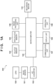
- FIG. 1A is a block diagram illustrating the configuration of an image capturing apparatus 204.
- 100 is a lens (a shooting lens).
- a fixed focal lens, a zoom lens, and the like exist as types of the lens 100.
- a microcomputer 103 described later, can obtain information such as a focal length, the current zoom position, the length of the lens barrel, and so on from the lens 100.
- the lens 100 can move the zoom position when zoom driving has been instructed by the microcomputer 103 or the like.
- the image capturing apparatus 204 may be what is known as an interchangeable lens-type camera, or may be an integrated lens-type camera.
- the apparatus includes a lens mount for attaching/detaching the lens 100, and can communicate with the attached lens 100 via the lens mount and obtain various types of lens information such as the specs, the current zoom position, and the like.
- the 101 is an image sensor.
- a CCD, a CMOS sensor, or the like is used as the image sensor 101.
- the image sensor 101 converts a subject image which has been formed by the lens 100 into an electrical signal.
- 102 is an A/D converter.
- the A/D converter 102 converts analog output signals from the image sensor 101 into digital signals.
- the microcomputer 103 is a microcomputer.
- the microcomputer 103 executes control of the image capturing apparatus 204 as a whole, including control of the various constituent elements, data processing, and the like.
- the microcomputer 103 carries out control in response to operation instructions from an operating unit 109, generates and plays back images to be displayed in a display unit 108, carries out network control via a communication unit 107, and so on.
- the microcomputer 103 furthermore implements all processing carried out by the image capturing apparatus 204, including communication processing when linking with a drone 205, control for receiving the state of the drone 205, processing for controlling the drone 205, and so on, which will be described later.
- the microcomputer 103 also processes control of communication with the lens 100.
- the microcomputer 103 also implements control pertaining to the lens 100, including whether or not the lens 100 is attached, obtaining the zoom position, obtaining a shortest shooting distance, controlling the zooming of the lens 100, and so on.
- the volatile memory 104 is volatile memory.
- the volatile memory 104 temporarily holds image data converted into a digital signal by the A/D converter 102.
- 105 is non-volatile memory.
- the non-volatile memory 105 holds control programs for the image capturing apparatus 204, executed by the microcomputer 103.
- the non-volatile memory 105 also stores setting values of the image capturing apparatus 204.
- the image processing unit 106 is an image processing unit.
- the image processing unit 106 carries out image processing on images that have been shot. Also, in cooperation with the microcomputer 103, the image processing unit 106 generates a live view image for confirming the composition, focus, and the like during shooting.
- the 107 is a communication unit.
- the communication unit 107 is implemented using technology such as wireless LAN, for example. With respect to the communication technology, there is no particular need to take into account the distinction between a wired connection, a wireless connection, and so on.
- the present embodiment assumes that the image capturing apparatus 204 communicates and links with the drone 205 via the communication unit 107.
- the linking method may be a method that uses a dedicated Software Development Kit (SDK, hereinafter), or a public API method such as the HTTP-based WebAPI.
- SDK Software Development Kit
- a control mechanism publicized by the image capturing apparatus 204 or the drone 205 may be used.
- the control may be carried out using a linking mechanism publicized by both the image capturing apparatus 204 and the drone 205.
- the linking method is not particularly limited.
- the display unit 108 is a display unit.
- the display unit 108 is controlled by the microcomputer 103, and displays menus, displays playback images, and the like.
- the display unit 108 also displays the live view image.
- 109 is an operating unit.
- the operating unit 109 can make operations in a user interface displayed in the display unit 108. Key operations, touch panel operations, and the like are assumed as operation methods for the operating unit 109.
- the recording medium 110 is recording medium.
- the recording medium 110 is compact flash (registered trademark) (CF), for example.
- the microcomputer 103 can write data from the volatile memory 104 into the recording medium 110, read out data saved in the recording medium 110 to the volatile memory 104, and the like.
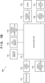
- FIG. 1B is a block diagram illustrating the configuration of the drone 205 (an unmanned aircraft), which is an example of a moving apparatus.
- 111 is a propeller.
- 112 is a flight control unit.
- the flight control unit 112 controls the flight of the drone 205 in tandem with a microcomputer 113.
- the flight control unit 112 carries out processing for controlling the drone 205 not to fly, control for obtaining the length and height of the propeller, and so on.
- the flight control unit 112 also carries out control so that the drone 205 itself (or an overall flight system including the mounted image capturing apparatus 204) does not collide (make contact) with an object such as a subject or the like. Note that any known technique can be used as a collision avoidance algorithm for the drone 205.
- the 113 is a microcomputer.
- the drone 205 is controlled by the microcomputer 113.
- the microcomputer 113 carries out a variety of processes by working in tandem with other constituent elements.
- 114 is volatile memory.
- 115 is non-volatile memory.
- the non-volatile memory 115 holds control programs executed by the microcomputer 113.
- the 116 is an external device communication unit.
- the external device communication unit 116 communicates with the communication unit 107 of the image capturing apparatus 204 in order to implement the link between the drone 205 and the image capturing apparatus 204.
- the communication method is not particularly limited, and may be wired or wireless.
- the communication protocol is also not limited. Commands for controlling the drone 205, notifications pertaining to the state of the drone 205, commands for controlling the image capturing apparatus 204, information pertaining to the lens 100 attached to the image capturing apparatus 204, and the like are conceivable as the content of the communication.
- 117 is an external device control unit.
- 118 is a gimbal.
- the image capturing apparatus 204 can be mounted to the drone 205 using the gimbal 118.
- the external device control unit 117 can, in tandem with the microcomputer 113, control the angle and the like of the image capturing apparatus 204 mounted to the gimbal 118.
- the 119 is a remote controller communication unit.
- the drone 205 is controlled by a user who holds a remote controller.
- the drone 205 may be a self-flying drone capable of flying in a state where a flight path and the like have been set in advance. If the drone 205 is controlled by remote controller operations made by the user, the microcomputer 113 receives control commands from the remote controller via the remote controller communication unit 119.
- the 120 is a light emission control unit.
- 121 is a light emitting unit.
- the light emitting unit 121 is built into the drone 205 in anticipation of nighttime flight or the like, so that the user can see where the drone 205 is flying.
- the light emission control unit 120 controls the emission of light by the light emitting unit 121.
- the light emitting unit 121 includes an LED or the like, for example, but the type of the light emitting unit is not particularly limited.
- FIG. 2 is a schematic diagram illustrating a remote control system for the drone 205. As illustrated in FIG. 2 , the image capturing apparatus 204 is mounted to the drone 205, supported by the gimbal 118 of the drone 205.
- the 200 is a remote controller for remotely controlling the drone 205.
- the user can control the drone 205 by operating the remote controller 200.
- the remote controller 200 is not limited to a remote controller prepared specifically for the drone 205.
- at least one piece of software for controlling the drone 205 may be installed in a mobile device such as a smartphone, a tablet device, and used as the remote controller 200.
- 201 is a display unit. Image data captured by the image capturing apparatus 204 mounted to the drone 205 can be displayed in the display unit 201 of the remote controller 200.
- the user can confirm the angle of view and the like of a still image or a moving image to be shot while viewing the display unit 201. Additionally, if some kind of error or the like has occurred while the image capturing apparatus 204 and the drone 205 are linked with each other to provide a function, the drone 205 notifies the remote controller 200 of the error, and the display unit 201 displays that notification.
- the 202 is an operating unit.
- the user can control the drone 205 to take off, land, travel forward, rotate, and so on.
- the user can also control the image capturing apparatus 204 via the drone 205.
- the drone 205 and the image capturing apparatus 204 can communicate with each other.
- the user can control the lens 100 attached to the image capturing apparatus 204 by operating the operating unit 202, for example.
- the user can carry out various types of control pertaining to the drone 205 and the image capturing apparatus 204 by using the remote controller 200, and the types of control that can be carried out are not particularly limited.
- the 203 represents communication between the remote controller 200 and the remote controller communication unit 119 of the drone 205.
- proportional control is assumed to be used for the remote controller radio waves for controlling the drone 205. It is assumed that the drone 205 will fly at an altitude of several hundreds of meters, and it is therefore basically assumed that long-distance wireless or wired communication will be used.
- the method of the communication between the remote controller 200 and the drone 205 is not particularly limited.
- a predetermined control device controls the image capturing apparatus 204 or the drone 205 as appropriate by taking into account the influence which the image capturing apparatus 204 and the drone 205 have on each other.
- the control device controls the image capturing apparatus 204 or the drone 205 based on at least one of information pertaining to the lens 100 of the image capturing apparatus 204 (lens information) and information pertaining to the drone 205 (moving apparatus information).
- information pertaining to the lens 100 of the image capturing apparatus 204 lens information
- information pertaining to the drone 205 moving apparatus information
- control device may be implemented by the microcomputer 103, or may be implemented by the microcomputer 113.
- the control device may be included in the image capturing apparatus 204, or may be included in the drone 205.
- the control device may be a device which is separate from the image capturing apparatus 204 and the drone 205 and which is capable of communicating with the image capturing apparatus 204 and the drone 205.
- the control device may be implemented by a combination of a plurality of microcomputers (e.g., the microcomputer 103 and the microcomputer 113).
- control device is implemented by the microcomputer 103
- the processing of each step in FIG. 3A to FIG. 3E is realized by the microcomputer 103 executing a control program stored in the non-volatile memory 105, unless otherwise specified.
- the control device is implemented by the microcomputer 113
- the processing of each step in FIG. 3A to FIG. 3E is realized by the microcomputer 113 executing a control program stored in the non-volatile memory 115, unless otherwise specified.
- the control device is a device which is separate from the image capturing apparatus 204 and the drone 205
- the control device includes a microcomputer and non-volatile memory, which are not shown. In this case, the processing of each step in FIG. 3A to FIG.
- 3E is realized by the microcomputer, which is not shown, executing a control program stored in the non-volatile memory, which is not shown, unless otherwise specified. If the control device is implemented by a combination of a plurality of microcomputers, the processing of each step in FIG. 3A to FIG. 3E is realized by the plurality of microcomputers handling different roles as appropriate, unless otherwise specified.
- the image capturing apparatus 204 and the drone 205 carry out communication pertaining to information and control commands as appropriate in accordance with the implementation of the control device. For example, when the control device requires information pertaining to the image capturing apparatus 204, no communication is necessary if the control device is included in the image capturing apparatus 204; however, if the control device is included in the drone 205, the image capturing apparatus 204 sends requested information to the drone 205. Furthermore, if the control device is at least partially implemented by a device which is separate from the image capturing apparatus 204 and the drone 205, the necessary information is communicated as appropriate between the image capturing apparatus 204/the drone 205 and the control device via a communication unit included in the separate device.
- control of the drone 205 is carried out by communicating control commands between the control device and the drone 205.
- control of the image capturing apparatus 204 is carried out by communicating control commands between the control device and the image capturing apparatus 204.
- the communication between the apparatuses may be carried out via another apparatus.
- the control device may send the control commands to the image capturing apparatus 204 via the drone 205.
- the distance between the image capturing apparatus 204 and the subject will drop below a shortest shooting distance (the shortest distance at which the subject can be brought into focus).
- the image capturing apparatus 204 may be unable to focus on the subject, and may therefore be unable to shoot the subject appropriately.
- the first example of control which does not form part of the invention but represents background art that is useful for understanding the invention will describe control for suppressing the occurrence of such a situation.
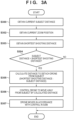
- FIG. 3A is a flowchart illustrating the first example of control executed by the control device in the control system including the control device, the image capturing apparatus 204, and the drone 205.
- the processing of this flowchart starts when a shooting request is issued to the image capturing apparatus 204. Note that if a so-called live view image is sent to the remote controller 200 from the drone 205, this flowchart may start in response to a request to send the live view image.
- the control device obtains information indicating the current distance between the image capturing apparatus 204 and a predetermined subject (the current subject distance).
- the subject distance can be obtained by using a function of the image capturing apparatus 204.
- the microcomputer 103 obtains the subject distance from a rangefinding unit (not shown) and provides the subject distance to the control device.
- the control device obtains the current zoom position of the lens 100.
- the current zoom position is obtained from the lens 100 by the lens 100 linking with the microcomputer 103.
- the control device obtains the shortest shooting distance based on the current zoom position.
- the control device determines whether or not the current subject distance obtained in S300 is less than the shortest shooting distance obtained in S303 (less than the shortest subject distance). If (subject distance) ⁇ (shortest shooting distance), the processing moves to S305, and if not, the processing of this flowchart ends.
- (Subject distance) ⁇ (shortest shooting distance) means that the drone 205 has come too close to the subject and the subject is therefore not in focus.
- the control device calculates a distance to move the drone 205. Specifically, the control device subtracts the subject distance obtained in S300 from the shortest shooting distance obtained in S303.
- the control device controls the drone 205 to move in a direction away from the subject by the distance calculated in S305.
- control device controls the drone 205 to move so that the subject distance becomes greater than or equal to the shortest shooting distance (greater than or equal to the shortest subject distance).
- the drone 205 moves away from the subject in accordance with the control by the control device carried out in S306.
- the control device controls the drone 205 so that (subject distance) ⁇ (shortest shooting distance). As a result, the occurrence of a situation in which the subject cannot be brought into focus can be suppressed.
- the flowchart illustrated in FIG. 3A is executed repeatedly when the drone 205 is sending a live view image or is shooting a moving image.
- the control device may make a notification to the remote controller 200 if (subject distance) ⁇ (shortest shooting distance). Having received the notification, the remote controller 200 may display guidance in the display unit 201, reading, for example, "the drone is closer to the subject than the shortest shooting distance. The drone will be moved away.” Alternatively, the control device may only notify the remote controller 200 without controlling the flight of the drone 205, and the remote controller 200 may display guidance in the display unit 201, reading "the drone is closer to the subject than the shortest shooting distance. Please move the drone away.”
- a predetermined part of the drone 205 may appear in the image that is shot.
- the second example of control will describe control for suppressing the occurrence of such a situation.
- FIG. 3B is a flowchart illustrating the second example of control executed by the control device in the control system including the control device, the image capturing apparatus 204, and the drone 205.
- the processing of this flowchart starts when a request to change the zoom position is issued to the image capturing apparatus 204.
- the control device obtains a target position corresponding to the request to change the zoom position (a zoom position to be moved to in zoom control for moving the zoom position).
- the control device obtains information indicating the position of the propeller 111 of the drone 205 (a height and a length).
- the flight control unit 112 and the microcomputer 113 of the drone 205 are used in this obtaining process.
- the control device calculates a zoom position at which the propeller 111 will be present within a shooting range, based on the height and the length of the propeller 111 obtained in S310.
- the control device may calculate the entire range of zoom positions in which the propeller 111 will be present within the shooting range, or may calculate the zoom position, furthest on the tele side, in which the propeller 111 will be present within the shooting range.
- the control device determines whether or not the propeller 111 will be present within the shooting range if the zoom position of the lens 100 is moved to the target position, based on the target position obtained in S309 and the zoom position obtained in S311. If the propeller 111 will be present in the shooting range, the processing moves to S313, and if not, the processing of this flowchart ends.
- the control device carries out zoom control of the lens 100 so as not to move to a zoom position at which the propeller 111 will be present in the shooting range. For example, the control device stops the movement of the zoom position of the lens 100 at the boundary of the range of zoom positions at which the propeller 111 will be present in the shooting range, so that the zoom position does not enter that range.
- the control device notifies the remote controller 200 of warning information indicating that zoom control has been carried out to ensure the zoom position does not move to a zoom position at which the propeller 111 will be present within the shooting range. In response to the notification, the remote controller 200 makes a warning display in the display unit 201.
- the control device carries out zoom control so that the lens 100 does not move to a zoom position at which the predetermined part will be present in the shooting range. This makes it possible to suppress the occurrence of a situation in which a predetermined part of the drone 205 (e.g., the propeller 111) appears in the image that is shot.
- control device may only notify the remote controller 200, without carrying out zoom control. This also applies to a third example of control, which will be described below.
- the third example of control is a variation on the second example of control.
- the third example of control will describe control for suppressing the occurrence of a situation in which a predetermined part of the drone 205 (e.g., the propeller 111) appears in the image that is shot.
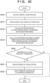
- FIG. 3C is a flowchart illustrating the third example of control executed by the control device in the control system including the control device, the image capturing apparatus 204, and the drone 205.
- the processing of this flowchart starts when a request to change the zoom position in the wide direction (toward a zoom position at which the propeller 111 will be present in the shooting range) is issued to the image capturing apparatus 204.
- the control device obtains the current zoom position of the lens 100 through the same processing such as that of S302 ( FIG. 3A ).
- the control device obtains information indicating the position of the propeller 111 of the drone 205 (a height and a length) through the same processing such as that of S310 ( FIG. 3B ).
- the control device calculates a zoom position at which the propeller 111 will be present within the shooting range through the same processing such as that of S311 ( FIG. 3B ).
- the control device calculates a difference between the current zoom position and the zoom position at which the propeller 111 will be present within the shooting range.
- the control device determines whether or not the difference calculated in S319 is less than a threshold. If the difference is less than the threshold (i.e., if the current zoom position is distanced from the zoom position at which the propeller 111 will be present in the shooting range by greater than or equal to the threshold), the processing moves to S321, and if not, the processing of this flowchart ends.
- the control device reduces the speed of the zoom control. In other words, the control device carries out control to move the zoom position of the lens 100 at a lower speed than when the current zoom position is distanced from the zoom position at which the propeller 111 will be present in the shooting range by greater than or equal to the threshold.
- the control device notifies the remote controller 200 of warning information indicating that the speed of the zoom control has been reduced. In response to the notification, the remote controller 200 makes a warning display in the display unit 201.
- the control device reduces the speed of the zoom control. This makes it possible to suppress the occurrence of a situation in which a predetermined part of the drone 205 (e.g., the propeller 111) appears in the image that is shot.
- the overall size of the flight system including the size of the image capturing apparatus 204 mounted to the drone 205, is required.
- the size of the flight system will change as well. As a result, it may not be possible to carry out effective collision avoidance.
- the fourth example of control will describe control for suppressing the occurrence of such a situation.
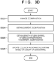
- FIG. 3D is a flowchart illustrating the fourth example of control executed by the control device in the control system including the control device, the image capturing apparatus 204, and the drone 205.
- the processing of this flowchart starts when a request to change the zoom position is issued to the image capturing apparatus 204.
- the control device changes the zoom position of the lens 100 in response to the request to change the zoom position.
- the control device obtains the current zoom position of the lens 100 through the same processing such as that of S302 ( FIG. 3A ).
- the control device obtains the length of the lens barrel of the lens 100 corresponding to the zoom position obtained in S324.
- the length of the lens barrel is obtained from the lens 100 by the lens 100 linking with the microcomputer 103, for example.
- the length of the lens barrel of the lens 100 at each of zoom positions may be stored in the non-volatile memory 105 in advance.
- the control device notifies the drone 205 of the length of the lens barrel obtained in S325, and controls the drone 205 to update the collision avoidance algorithm (or change parameters) based on the length of the lens barrel.
- the control device updates the collision avoidance algorithm of the drone 205 based on the length of the lens barrel. More specifically, by updating the collision avoidance algorithm based on the length of the lens barrel, the control device controls the movement (flight) of the drone 205 so that at least the lens barrel does not make contact with an object (an obstruction). As a result, the drone 205 can effectively avoid a collision with the obstruction even when the length of the lens barrel of the lens 100 changes.
- control can also be applied in various types of flight control algorithms for controlling actions such as steering, rotation, flight speed, and so on, for example.
- the lens barrel is very long when the lens 100 is at the tele end, and thus the weight balance and moment of the system constituted by the control device, the image capturing apparatus 204, and the drone 205 are different from when the lens 100 is at the wide end.
- the control device updates the flight control algorithm (or changes parameters) based on the length, weight, or the like of the lens barrel.
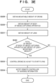
- FIG. 3E is a flowchart illustrating the fifth example of control executed by the control device in the control system including the control device, the image capturing apparatus 204, and the drone 205. The processing of this flowchart starts when a flight start request is issued to the drone 205.
- the control device obtains the mountable weight of the drone 205.
- the mountable weight is stored in the non-volatile memory 115 of the drone 205, for example.
- the control device obtains the weight of the body of the image capturing apparatus 204.
- the weight of the body of the image capturing apparatus 204 is stored in the non-volatile memory 105 of the image capturing apparatus 204, for example.
- the control device obtains the weight of the lens 100.
- the weight is obtained from the lens 100 by the lens 100 linking with the microcomputer 103, for example.
- the weight of each of lens types may be stored in the non-volatile memory 105 in advance.
- the control device determines whether or not the total of the weight of the body of the image capturing apparatus 204 and the weight of the lens 100 exceeds the mountable weight. If the total of the weight of the body of the image capturing apparatus 204 and the weight of the lens 100 exceeds the mountable weight, the processing moves to S333, and if not, the processing of this flowchart ends.
- the control device controls the drone 205 so as not to start flying.
- the control device notifies the remote controller 200 of warning information indicating that the drone 205 has been controlled so as not to start flying. In response to the notification, the remote controller 200 makes a warning display in the display unit 201.
- control device controls the drone 205 so as not to start flying when the total of the weight of the body of the image capturing apparatus 204 and the weight of the lens 100 exceeds the mountable weight. As a result, the likelihood that the drone 205 cannot fly correctly can be reduced.
- the fifth example of control can be changed so as to control the travel of the drone 205.
- the control device controls the drone 205 so as not to start traveling.
- the control device can control any desired type of movement, including flying and traveling.
- the control device controls the drone 205 based on information pertaining to the lens 100, controls the lens 100 based on information pertaining to the lens 100 and information pertaining to the drone 205, and so on.
- the image capturing apparatus 204 or the drone 205 can be controlled more appropriately in a situation where the image capturing apparatus 204 is mounted to the drone 205.
- the moving apparatus of the present embodiment is not limited thereto, and it is not necessary that the moving apparatus fly.
- the moving apparatus may be a vehicle that travels over land, for example.
- the second to fifth examples of control describe a shooting request, a request to change the zoom position, and a flight start request for the drone 205 as examples of triggers for carrying out control.
- various types of control can be realized by communicating information in advance, in addition to the aforementioned triggers.
- the various types of control can also be realized by communicating information of the image capturing apparatus 204 to the drone 205, or communicating information of the drone 205 to the image capturing apparatus 204, in advance.
- the present invention can also be realized as a process executed by supplying a program implementing one or more functions of the above-described embodiment to a system or apparatus over a network or by a storage medium and then causing one or more processors of a computer of the system or apparatus to read out and execute the program.
- the invention can also be realized by a circuit (an ASIC, for example) that implements one or more functions.
Landscapes
- Engineering & Computer Science (AREA)
- Physics & Mathematics (AREA)
- Multimedia (AREA)
- Signal Processing (AREA)
- General Physics & Mathematics (AREA)
- Aviation & Aerospace Engineering (AREA)
- Mechanical Engineering (AREA)
- Remote Sensing (AREA)
- Optics & Photonics (AREA)
- Combustion & Propulsion (AREA)
- Chemical & Material Sciences (AREA)
- Radar, Positioning & Navigation (AREA)
- Automation & Control Theory (AREA)
- General Engineering & Computer Science (AREA)
- Studio Devices (AREA)
- Lens Barrels (AREA)
- Control Of Position, Course, Altitude, Or Attitude Of Moving Bodies (AREA)
Applications Claiming Priority (2)
| Application Number | Priority Date | Filing Date | Title |
|---|---|---|---|
| JP2017160529A JP7057637B2 (ja) | 2017-08-23 | 2017-08-23 | 制御装置、制御システム、制御方法、プログラム、及び記憶媒体 |
| PCT/JP2018/025341 WO2019039099A1 (ja) | 2017-08-23 | 2018-07-04 | 制御装置、制御システム、制御方法、プログラム、及び記憶媒体 |
Publications (3)
| Publication Number | Publication Date |
|---|---|
| EP3687159A1 EP3687159A1 (en) | 2020-07-29 |
| EP3687159A4 EP3687159A4 (en) | 2021-08-18 |
| EP3687159B1 true EP3687159B1 (en) | 2023-05-10 |
Family
ID=65440031
Family Applications (1)
| Application Number | Title | Priority Date | Filing Date |
|---|---|---|---|
| EP18848454.7A Active EP3687159B1 (en) | 2017-08-23 | 2018-07-04 | Control device, control system, control method, program and recording medium |
Country Status (6)
| Country | Link |
|---|---|
| US (1) | US11310416B2 (enExample) |
| EP (1) | EP3687159B1 (enExample) |
| JP (1) | JP7057637B2 (enExample) |
| KR (1) | KR102340617B1 (enExample) |
| CN (1) | CN111034172B (enExample) |
| WO (1) | WO2019039099A1 (enExample) |
Families Citing this family (13)
| Publication number | Priority date | Publication date | Assignee | Title |
|---|---|---|---|---|
| WO2020107372A1 (zh) * | 2018-11-30 | 2020-06-04 | 深圳市大疆创新科技有限公司 | 拍摄设备的控制方法、装置、设备及存储介质 |
| WO2021024627A1 (ja) * | 2019-08-08 | 2021-02-11 | ソニー株式会社 | 情報処理装置、移動体、情報処理システム、情報処理方法及びプログラム |
| JP6878738B1 (ja) * | 2020-02-12 | 2021-06-02 | エスゼット ディージェイアイ テクノロジー カンパニー リミテッドSz Dji Technology Co.,Ltd | 制御装置、撮像システム、移動体、制御方法、及びプログラム |
| US20230350413A1 (en) * | 2020-07-20 | 2023-11-02 | Canon U.S.A., Inc. | Control system for an unmanned autonomous vehicle |
| JP7104114B2 (ja) | 2020-08-21 | 2022-07-20 | 楽天グループ株式会社 | 飛行体、システム、及び、方法 |
| CN112401752B (zh) * | 2020-11-04 | 2022-05-17 | 北京石头创新科技有限公司 | 一种检测未知障碍物的方法、装置、介质和电子设备 |
| CN118450230A (zh) * | 2020-12-31 | 2024-08-06 | 深圳市大疆创新科技有限公司 | 拍摄设备、控制设备、遥控设备、移动控制系统和可穿戴设备 |
| WO2022141348A1 (en) | 2020-12-31 | 2022-07-07 | SZ DJI Technology Co., Ltd. | Systems, devices, and methods supporting multiple photography modes with a control device |
| JP7696769B2 (ja) | 2021-06-29 | 2025-06-23 | キヤノン株式会社 | 無人飛行装置および無人飛行装置の制御方法 |
| US20230058405A1 (en) * | 2021-08-20 | 2023-02-23 | Sony Group Corporation | Unmanned aerial vehicle (uav) swarm control |
| JP7776972B2 (ja) | 2021-11-25 | 2025-11-27 | キヤノン株式会社 | 撮像装置、制御方法およびプログラム |
| CN114849234B (zh) * | 2022-06-01 | 2025-07-25 | 网易(杭州)网络有限公司 | 虚拟镜头控制方法、装置、存储介质和电子设备 |
| JP2024033521A (ja) | 2022-08-30 | 2024-03-13 | キヤノン株式会社 | 撮像システム及びその制御方法とプログラム |
Family Cites Families (28)
| Publication number | Priority date | Publication date | Assignee | Title |
|---|---|---|---|---|
| FI55682C (fi) | 1977-09-06 | 1979-09-10 | Viljanmaa Antti | Spaennanordning foer skinn |
| JPS56159165A (en) | 1980-05-14 | 1981-12-08 | Hiraoka Shokusen | Resin coated cloth silk having large tear strength |
| US5305038A (en) * | 1991-07-30 | 1994-04-19 | Asahi Kogaku Kogyo Kabushiki Kaisha | Zoom lens camera |
| JP2004288100A (ja) * | 2003-03-25 | 2004-10-14 | Minolta Co Ltd | 撮像装置及び移動体カメラ |
| JP2012023546A (ja) * | 2010-07-14 | 2012-02-02 | Jvc Kenwood Corp | 制御装置、立体映像撮像装置、および制御方法 |
| CN102809969A (zh) * | 2011-06-03 | 2012-12-05 | 鸿富锦精密工业(深圳)有限公司 | 无人飞行载具控制系统及方法 |
| JP6003530B2 (ja) * | 2012-10-25 | 2016-10-05 | リコーイメージング株式会社 | ズームレンズ系 |
| JP5561843B1 (ja) * | 2013-01-07 | 2014-07-30 | 株式会社amuse oneself | 制御装置、測量システム、プログラム及び記録媒体並びに計測方法 |
| US8903568B1 (en) | 2013-07-31 | 2014-12-02 | SZ DJI Technology Co., Ltd | Remote control method and terminal |
| CN103426282A (zh) * | 2013-07-31 | 2013-12-04 | 深圳市大疆创新科技有限公司 | 遥控方法及终端 |
| CN107168352B (zh) * | 2014-07-30 | 2020-07-14 | 深圳市大疆创新科技有限公司 | 目标追踪系统及方法 |
| JP2016111414A (ja) * | 2014-12-03 | 2016-06-20 | コニカミノルタ株式会社 | 飛行体の位置検出システム及び飛行体 |
| JP6475568B2 (ja) | 2015-05-19 | 2019-02-27 | オリンパス株式会社 | 撮像装置および飛行制御方法 |
| US11140326B2 (en) * | 2015-05-22 | 2021-10-05 | The United States Of America, As Represented By The Secretary Of The Navy | Aerial video based point, distance, and velocity real-time measurement system |
| JP6367759B2 (ja) | 2015-06-01 | 2018-08-01 | 日本電信電話株式会社 | 表示画像ズーム端末、表示画像ズーム方法及び表示画像ズームプログラム |
| JP2017034444A (ja) * | 2015-07-31 | 2017-02-09 | オリンパス株式会社 | 撮像装置および撮像方法 |
| FR3041134B1 (fr) * | 2015-09-10 | 2017-09-29 | Parrot | Drone avec camera a visee frontale dont les parametres de controle, notamment l'autoexposition, sont rendus independant de l'attitude. |
| WO2017045116A1 (en) * | 2015-09-15 | 2017-03-23 | SZ DJI Technology Co., Ltd. | System and method for supporting smooth target following |
| WO2017066927A1 (en) * | 2015-10-20 | 2017-04-27 | SZ DJI Technology Co., Ltd. | Systems, methods, and devices for setting camera parameters |
| JP6758828B2 (ja) * | 2015-12-15 | 2020-09-23 | キヤノン株式会社 | 撮像システムおよびその制御方法 |
| JP6318455B1 (ja) * | 2016-06-13 | 2018-05-09 | エスゼット ディージェイアイ テクノロジー カンパニー リミテッドSz Dji Technology Co.,Ltd | 制御装置、撮像装置、移動体、制御方法及びプログラム |
| JP6500849B2 (ja) * | 2016-06-23 | 2019-04-17 | カシオ計算機株式会社 | 撮像装置、撮像方法及びプログラム |
| JP6146520B1 (ja) * | 2016-07-12 | 2017-06-14 | エスゼット ディージェイアイ テクノロジー カンパニー リミテッドSz Dji Technology Co., Ltd | 光学装置、移動体、保持位置調整方法、及びプログラム |
| WO2018010095A1 (en) * | 2016-07-12 | 2018-01-18 | SZ DJI Technology Co., Ltd. | System for balancing center of gravity of a zoom lens |
| JP6103672B1 (ja) * | 2016-07-20 | 2017-03-29 | エスゼット ディージェイアイ テクノロジー カンパニー リミテッドSz Dji Technology Co.,Ltd | 制御装置、撮像装置、移動体、制御方法、及びプログラム |
| WO2018014254A1 (en) * | 2016-07-20 | 2018-01-25 | SZ DJI Technology Co., Ltd. | Method and apparatus for zooming relative to an object copyright notice |
| CN107079106B (zh) * | 2016-09-26 | 2020-11-13 | 深圳市大疆创新科技有限公司 | 对焦方法和装置、图像拍摄方法和装置及摄像系统 |
| CN110119154A (zh) * | 2016-11-30 | 2019-08-13 | 深圳市大疆创新科技有限公司 | 飞行器的控制方法、装置和设备以及飞行器 |
-
2017
- 2017-08-23 JP JP2017160529A patent/JP7057637B2/ja active Active
-
2018
- 2018-07-04 KR KR1020207006659A patent/KR102340617B1/ko active Active
- 2018-07-04 CN CN201880054103.2A patent/CN111034172B/zh active Active
- 2018-07-04 WO PCT/JP2018/025341 patent/WO2019039099A1/ja not_active Ceased
- 2018-07-04 EP EP18848454.7A patent/EP3687159B1/en active Active
-
2020
- 2020-01-21 US US16/748,485 patent/US11310416B2/en active Active
Also Published As
| Publication number | Publication date |
|---|---|
| CN111034172A (zh) | 2020-04-17 |
| CN111034172B (zh) | 2021-11-16 |
| JP2019041185A (ja) | 2019-03-14 |
| US20200162667A1 (en) | 2020-05-21 |
| WO2019039099A1 (ja) | 2019-02-28 |
| EP3687159A1 (en) | 2020-07-29 |
| US11310416B2 (en) | 2022-04-19 |
| KR20200039725A (ko) | 2020-04-16 |
| EP3687159A4 (en) | 2021-08-18 |
| JP7057637B2 (ja) | 2022-04-20 |
| KR102340617B1 (ko) | 2021-12-20 |
Similar Documents
| Publication | Publication Date | Title |
|---|---|---|
| EP3687159B1 (en) | Control device, control system, control method, program and recording medium | |
| JP6239993B2 (ja) | 撮像装置、表示装置、及び制御方法 | |
| EP3540506B1 (en) | Optical apparatus, control method, and computer program | |
| KR20190094115A (ko) | 원격 조작 시스템, 및 그 통신 방법 | |
| JP6697340B2 (ja) | 撮影機器、移動撮影装置、撮影用移動体及び移動体用撮影制御装置 | |
| CN108141533A (zh) | 摄像系统、视角调整方法以及视角调整程序 | |
| US20230341079A1 (en) | Control method based on image capturing apparatus, control method and apparatus for gimbal | |
| CN107431749B (zh) | 一种跟焦器控制方法和装置及系统 | |
| JP6543946B2 (ja) | ブレ補正装置、カメラ及び電子機器 | |
| JP6758828B2 (ja) | 撮像システムおよびその制御方法 | |
| CN108419052B (zh) | 一种多台无人机全景成像方法 | |
| CN108737698B (zh) | 图像稳定设备和方法、摄像设备、摄像系统和存储介质 | |
| CN105100581A (zh) | 变焦透镜装置 | |
| JP6685714B2 (ja) | 移動撮像装置の制御装置、移動撮像装置、および移動撮像装置の制御方法 | |
| US12063435B2 (en) | Image capturing apparatus, control method, and storage medium | |
| US11810386B2 (en) | Image capture apparatus and control method | |
| US20220404841A1 (en) | Information processing system, information processing method, and information processing program | |
| JP2023065092A (ja) | 測距装置、画像処理装置、方法及びプログラム | |
| US11765454B2 (en) | Image control method and device, and mobile platform | |
| US12041356B2 (en) | Imaging device, imaging system, control method, program, and storage medium | |
| JP7483357B2 (ja) | レンズ装置および撮像装置 | |
| JP2025129981A (ja) | 撮像装置、撮像装置の制御方法、及びプログラム | |
| JP2018113545A (ja) | 操作制御方法、移動撮影装置、コントローラ、及びプログラム | |
| JP2019080240A (ja) | 画像処理装置、画像処理方法、及び、プログラム |
Legal Events
| Date | Code | Title | Description |
|---|---|---|---|
| STAA | Information on the status of an ep patent application or granted ep patent |
Free format text: STATUS: THE INTERNATIONAL PUBLICATION HAS BEEN MADE |
|
| PUAI | Public reference made under article 153(3) epc to a published international application that has entered the european phase |
Free format text: ORIGINAL CODE: 0009012 |
|
| STAA | Information on the status of an ep patent application or granted ep patent |
Free format text: STATUS: REQUEST FOR EXAMINATION WAS MADE |
|
| 17P | Request for examination filed |
Effective date: 20200323 |
|
| AK | Designated contracting states |
Kind code of ref document: A1 Designated state(s): AL AT BE BG CH CY CZ DE DK EE ES FI FR GB GR HR HU IE IS IT LI LT LU LV MC MK MT NL NO PL PT RO RS SE SI SK SM TR |
|
| AX | Request for extension of the european patent |
Extension state: BA ME |
|
| DAV | Request for validation of the european patent (deleted) | ||
| DAX | Request for extension of the european patent (deleted) | ||
| A4 | Supplementary search report drawn up and despatched |
Effective date: 20210721 |
|
| RIC1 | Information provided on ipc code assigned before grant |
Ipc: H04N 5/232 20060101AFI20210715BHEP Ipc: G02B 7/08 20210101ALI20210715BHEP Ipc: G02B 7/10 20210101ALI20210715BHEP Ipc: G03B 15/00 20210101ALI20210715BHEP |
|
| GRAP | Despatch of communication of intention to grant a patent |
Free format text: ORIGINAL CODE: EPIDOSNIGR1 |
|
| STAA | Information on the status of an ep patent application or granted ep patent |
Free format text: STATUS: GRANT OF PATENT IS INTENDED |
|
| INTG | Intention to grant announced |
Effective date: 20221215 |
|
| RAP3 | Party data changed (applicant data changed or rights of an application transferred) |
Owner name: CANON KABUSHIKI KAISHA |
|
| GRAS | Grant fee paid |
Free format text: ORIGINAL CODE: EPIDOSNIGR3 |
|
| GRAA | (expected) grant |
Free format text: ORIGINAL CODE: 0009210 |
|
| STAA | Information on the status of an ep patent application or granted ep patent |
Free format text: STATUS: THE PATENT HAS BEEN GRANTED |
|
| AK | Designated contracting states |
Kind code of ref document: B1 Designated state(s): AL AT BE BG CH CY CZ DE DK EE ES FI FR GB GR HR HU IE IS IT LI LT LU LV MC MK MT NL NO PL PT RO RS SE SI SK SM TR |
|
| REG | Reference to a national code |
Ref country code: GB Ref legal event code: FG4D |
|
| REG | Reference to a national code |
Ref country code: AT Ref legal event code: REF Ref document number: 1567890 Country of ref document: AT Kind code of ref document: T Effective date: 20230515 Ref country code: CH Ref legal event code: EP |
|
| REG | Reference to a national code |
Ref country code: DE Ref legal event code: R096 Ref document number: 602018049777 Country of ref document: DE |
|
| REG | Reference to a national code |
Ref country code: IE Ref legal event code: FG4D |
|
| REG | Reference to a national code |
Ref country code: LT Ref legal event code: MG9D |
|
| REG | Reference to a national code |
Ref country code: NL Ref legal event code: MP Effective date: 20230510 |
|
| REG | Reference to a national code |
Ref country code: AT Ref legal event code: MK05 Ref document number: 1567890 Country of ref document: AT Kind code of ref document: T Effective date: 20230510 |
|
| PG25 | Lapsed in a contracting state [announced via postgrant information from national office to epo] |
Ref country code: SE Free format text: LAPSE BECAUSE OF FAILURE TO SUBMIT A TRANSLATION OF THE DESCRIPTION OR TO PAY THE FEE WITHIN THE PRESCRIBED TIME-LIMIT Effective date: 20230510 Ref country code: PT Free format text: LAPSE BECAUSE OF FAILURE TO SUBMIT A TRANSLATION OF THE DESCRIPTION OR TO PAY THE FEE WITHIN THE PRESCRIBED TIME-LIMIT Effective date: 20230911 Ref country code: NO Free format text: LAPSE BECAUSE OF FAILURE TO SUBMIT A TRANSLATION OF THE DESCRIPTION OR TO PAY THE FEE WITHIN THE PRESCRIBED TIME-LIMIT Effective date: 20230810 Ref country code: NL Free format text: LAPSE BECAUSE OF FAILURE TO SUBMIT A TRANSLATION OF THE DESCRIPTION OR TO PAY THE FEE WITHIN THE PRESCRIBED TIME-LIMIT Effective date: 20230510 Ref country code: ES Free format text: LAPSE BECAUSE OF FAILURE TO SUBMIT A TRANSLATION OF THE DESCRIPTION OR TO PAY THE FEE WITHIN THE PRESCRIBED TIME-LIMIT Effective date: 20230510 Ref country code: AT Free format text: LAPSE BECAUSE OF FAILURE TO SUBMIT A TRANSLATION OF THE DESCRIPTION OR TO PAY THE FEE WITHIN THE PRESCRIBED TIME-LIMIT Effective date: 20230510 |
|
| PG25 | Lapsed in a contracting state [announced via postgrant information from national office to epo] |
Ref country code: RS Free format text: LAPSE BECAUSE OF FAILURE TO SUBMIT A TRANSLATION OF THE DESCRIPTION OR TO PAY THE FEE WITHIN THE PRESCRIBED TIME-LIMIT Effective date: 20230510 Ref country code: PL Free format text: LAPSE BECAUSE OF FAILURE TO SUBMIT A TRANSLATION OF THE DESCRIPTION OR TO PAY THE FEE WITHIN THE PRESCRIBED TIME-LIMIT Effective date: 20230510 Ref country code: LV Free format text: LAPSE BECAUSE OF FAILURE TO SUBMIT A TRANSLATION OF THE DESCRIPTION OR TO PAY THE FEE WITHIN THE PRESCRIBED TIME-LIMIT Effective date: 20230510 Ref country code: LT Free format text: LAPSE BECAUSE OF FAILURE TO SUBMIT A TRANSLATION OF THE DESCRIPTION OR TO PAY THE FEE WITHIN THE PRESCRIBED TIME-LIMIT Effective date: 20230510 Ref country code: IS Free format text: LAPSE BECAUSE OF FAILURE TO SUBMIT A TRANSLATION OF THE DESCRIPTION OR TO PAY THE FEE WITHIN THE PRESCRIBED TIME-LIMIT Effective date: 20230910 Ref country code: HR Free format text: LAPSE BECAUSE OF FAILURE TO SUBMIT A TRANSLATION OF THE DESCRIPTION OR TO PAY THE FEE WITHIN THE PRESCRIBED TIME-LIMIT Effective date: 20230510 Ref country code: GR Free format text: LAPSE BECAUSE OF FAILURE TO SUBMIT A TRANSLATION OF THE DESCRIPTION OR TO PAY THE FEE WITHIN THE PRESCRIBED TIME-LIMIT Effective date: 20230811 |
|
| PG25 | Lapsed in a contracting state [announced via postgrant information from national office to epo] |
Ref country code: FI Free format text: LAPSE BECAUSE OF FAILURE TO SUBMIT A TRANSLATION OF THE DESCRIPTION OR TO PAY THE FEE WITHIN THE PRESCRIBED TIME-LIMIT Effective date: 20230510 |
|
| PG25 | Lapsed in a contracting state [announced via postgrant information from national office to epo] |
Ref country code: SK Free format text: LAPSE BECAUSE OF FAILURE TO SUBMIT A TRANSLATION OF THE DESCRIPTION OR TO PAY THE FEE WITHIN THE PRESCRIBED TIME-LIMIT Effective date: 20230510 |
|
| PG25 | Lapsed in a contracting state [announced via postgrant information from national office to epo] |
Ref country code: SM Free format text: LAPSE BECAUSE OF FAILURE TO SUBMIT A TRANSLATION OF THE DESCRIPTION OR TO PAY THE FEE WITHIN THE PRESCRIBED TIME-LIMIT Effective date: 20230510 Ref country code: SK Free format text: LAPSE BECAUSE OF FAILURE TO SUBMIT A TRANSLATION OF THE DESCRIPTION OR TO PAY THE FEE WITHIN THE PRESCRIBED TIME-LIMIT Effective date: 20230510 Ref country code: RO Free format text: LAPSE BECAUSE OF FAILURE TO SUBMIT A TRANSLATION OF THE DESCRIPTION OR TO PAY THE FEE WITHIN THE PRESCRIBED TIME-LIMIT Effective date: 20230510 Ref country code: EE Free format text: LAPSE BECAUSE OF FAILURE TO SUBMIT A TRANSLATION OF THE DESCRIPTION OR TO PAY THE FEE WITHIN THE PRESCRIBED TIME-LIMIT Effective date: 20230510 Ref country code: DK Free format text: LAPSE BECAUSE OF FAILURE TO SUBMIT A TRANSLATION OF THE DESCRIPTION OR TO PAY THE FEE WITHIN THE PRESCRIBED TIME-LIMIT Effective date: 20230510 Ref country code: CZ Free format text: LAPSE BECAUSE OF FAILURE TO SUBMIT A TRANSLATION OF THE DESCRIPTION OR TO PAY THE FEE WITHIN THE PRESCRIBED TIME-LIMIT Effective date: 20230510 |
|
| REG | Reference to a national code |
Ref country code: DE Ref legal event code: R119 Ref document number: 602018049777 Country of ref document: DE |
|
| PG25 | Lapsed in a contracting state [announced via postgrant information from national office to epo] |
Ref country code: MC Free format text: LAPSE BECAUSE OF FAILURE TO SUBMIT A TRANSLATION OF THE DESCRIPTION OR TO PAY THE FEE WITHIN THE PRESCRIBED TIME-LIMIT Effective date: 20230510 |
|
| PG25 | Lapsed in a contracting state [announced via postgrant information from national office to epo] |
Ref country code: MC Free format text: LAPSE BECAUSE OF FAILURE TO SUBMIT A TRANSLATION OF THE DESCRIPTION OR TO PAY THE FEE WITHIN THE PRESCRIBED TIME-LIMIT Effective date: 20230510 |
|
| REG | Reference to a national code |
Ref country code: CH Ref legal event code: PL |
|
| PLBE | No opposition filed within time limit |
Free format text: ORIGINAL CODE: 0009261 |
|
| STAA | Information on the status of an ep patent application or granted ep patent |
Free format text: STATUS: NO OPPOSITION FILED WITHIN TIME LIMIT |
|
| REG | Reference to a national code |
Ref country code: BE Ref legal event code: MM Effective date: 20230731 |
|
| PG25 | Lapsed in a contracting state [announced via postgrant information from national office to epo] |
Ref country code: LU Free format text: LAPSE BECAUSE OF NON-PAYMENT OF DUE FEES Effective date: 20230704 |
|
| PG25 | Lapsed in a contracting state [announced via postgrant information from national office to epo] |
Ref country code: LU Free format text: LAPSE BECAUSE OF NON-PAYMENT OF DUE FEES Effective date: 20230704 |
|
| 26N | No opposition filed |
Effective date: 20240213 |
|
| REG | Reference to a national code |
Ref country code: IE Ref legal event code: MM4A |
|
| PG25 | Lapsed in a contracting state [announced via postgrant information from national office to epo] |
Ref country code: DE Free format text: LAPSE BECAUSE OF NON-PAYMENT OF DUE FEES Effective date: 20240201 Ref country code: CH Free format text: LAPSE BECAUSE OF NON-PAYMENT OF DUE FEES Effective date: 20230731 |
|
| PG25 | Lapsed in a contracting state [announced via postgrant information from national office to epo] |
Ref country code: SI Free format text: LAPSE BECAUSE OF FAILURE TO SUBMIT A TRANSLATION OF THE DESCRIPTION OR TO PAY THE FEE WITHIN THE PRESCRIBED TIME-LIMIT Effective date: 20230510 |
|
| PG25 | Lapsed in a contracting state [announced via postgrant information from national office to epo] |
Ref country code: SI Free format text: LAPSE BECAUSE OF FAILURE TO SUBMIT A TRANSLATION OF THE DESCRIPTION OR TO PAY THE FEE WITHIN THE PRESCRIBED TIME-LIMIT Effective date: 20230510 Ref country code: IT Free format text: LAPSE BECAUSE OF FAILURE TO SUBMIT A TRANSLATION OF THE DESCRIPTION OR TO PAY THE FEE WITHIN THE PRESCRIBED TIME-LIMIT Effective date: 20230510 Ref country code: FR Free format text: LAPSE BECAUSE OF NON-PAYMENT OF DUE FEES Effective date: 20230710 Ref country code: BE Free format text: LAPSE BECAUSE OF NON-PAYMENT OF DUE FEES Effective date: 20230731 |
|
| PG25 | Lapsed in a contracting state [announced via postgrant information from national office to epo] |
Ref country code: IE Free format text: LAPSE BECAUSE OF NON-PAYMENT OF DUE FEES Effective date: 20230704 |
|
| PG25 | Lapsed in a contracting state [announced via postgrant information from national office to epo] |
Ref country code: IE Free format text: LAPSE BECAUSE OF NON-PAYMENT OF DUE FEES Effective date: 20230704 |
|
| PG25 | Lapsed in a contracting state [announced via postgrant information from national office to epo] |
Ref country code: BG Free format text: LAPSE BECAUSE OF FAILURE TO SUBMIT A TRANSLATION OF THE DESCRIPTION OR TO PAY THE FEE WITHIN THE PRESCRIBED TIME-LIMIT Effective date: 20230510 |
|
| PG25 | Lapsed in a contracting state [announced via postgrant information from national office to epo] |
Ref country code: BG Free format text: LAPSE BECAUSE OF FAILURE TO SUBMIT A TRANSLATION OF THE DESCRIPTION OR TO PAY THE FEE WITHIN THE PRESCRIBED TIME-LIMIT Effective date: 20230510 |
|
| PGFP | Annual fee paid to national office [announced via postgrant information from national office to epo] |
Ref country code: GB Payment date: 20250619 Year of fee payment: 8 |
|
| PG25 | Lapsed in a contracting state [announced via postgrant information from national office to epo] |
Ref country code: CY Free format text: LAPSE BECAUSE OF FAILURE TO SUBMIT A TRANSLATION OF THE DESCRIPTION OR TO PAY THE FEE WITHIN THE PRESCRIBED TIME-LIMIT; INVALID AB INITIO Effective date: 20180704 |
|
| PG25 | Lapsed in a contracting state [announced via postgrant information from national office to epo] |
Ref country code: HU Free format text: LAPSE BECAUSE OF FAILURE TO SUBMIT A TRANSLATION OF THE DESCRIPTION OR TO PAY THE FEE WITHIN THE PRESCRIBED TIME-LIMIT; INVALID AB INITIO Effective date: 20180704 |
|
| PG25 | Lapsed in a contracting state [announced via postgrant information from national office to epo] |
Ref country code: TR Free format text: LAPSE BECAUSE OF FAILURE TO SUBMIT A TRANSLATION OF THE DESCRIPTION OR TO PAY THE FEE WITHIN THE PRESCRIBED TIME-LIMIT Effective date: 20230510 |