WO2019039063A1 - 飛行体用安全装置および飛行体 - Google Patents
飛行体用安全装置および飛行体 Download PDFInfo
- Publication number
- WO2019039063A1 WO2019039063A1 PCT/JP2018/023359 JP2018023359W WO2019039063A1 WO 2019039063 A1 WO2019039063 A1 WO 2019039063A1 JP 2018023359 W JP2018023359 W JP 2018023359W WO 2019039063 A1 WO2019039063 A1 WO 2019039063A1
- Authority
- WO
- WIPO (PCT)
- Prior art keywords
- bag
- deployed
- safety device
- shape
- folded
- Prior art date
Links
- 230000007246 mechanism Effects 0.000 claims abstract description 33
- 239000003795 chemical substances by application Substances 0.000 claims description 45
- 238000002347 injection Methods 0.000 claims description 36
- 239000007924 injection Substances 0.000 claims description 36
- 238000002485 combustion reaction Methods 0.000 claims description 19
- 239000012212 insulator Substances 0.000 claims description 15
- 239000003814 drug Substances 0.000 claims description 6
- 239000007789 gas Substances 0.000 description 192
- 230000004048 modification Effects 0.000 description 34
- 238000012986 modification Methods 0.000 description 34
- 239000002585 base Substances 0.000 description 18
- 239000004744 fabric Substances 0.000 description 16
- 229910052751 metal Inorganic materials 0.000 description 14
- 239000002184 metal Substances 0.000 description 14
- 238000000034 method Methods 0.000 description 10
- 238000010586 diagram Methods 0.000 description 8
- 229920002050 silicone resin Polymers 0.000 description 8
- 239000000203 mixture Substances 0.000 description 7
- 239000002360 explosive Substances 0.000 description 6
- 239000000463 material Substances 0.000 description 6
- -1 polyethylene terephthalate Polymers 0.000 description 6
- OKTJSMMVPCPJKN-UHFFFAOYSA-N Carbon Chemical compound [C] OKTJSMMVPCPJKN-UHFFFAOYSA-N 0.000 description 5
- 239000011230 binding agent Substances 0.000 description 4
- 239000011247 coating layer Substances 0.000 description 4
- 238000010276 construction Methods 0.000 description 4
- 229920001971 elastomer Polymers 0.000 description 4
- 230000005611 electricity Effects 0.000 description 4
- 239000007800 oxidant agent Substances 0.000 description 4
- 239000005060 rubber Substances 0.000 description 4
- 239000004925 Acrylic resin Substances 0.000 description 3
- QPLDLSVMHZLSFG-UHFFFAOYSA-N Copper oxide Chemical compound [Cu]=O QPLDLSVMHZLSFG-UHFFFAOYSA-N 0.000 description 3
- 229920002292 Nylon 6 Polymers 0.000 description 3
- 229920002302 Nylon 6,6 Polymers 0.000 description 3
- 230000001934 delay Effects 0.000 description 3
- 230000003111 delayed effect Effects 0.000 description 3
- 230000000694 effects Effects 0.000 description 3
- 239000002245 particle Substances 0.000 description 3
- 239000000843 powder Substances 0.000 description 3
- 229910001285 shape-memory alloy Inorganic materials 0.000 description 3
- QGZKDVFQNNGYKY-UHFFFAOYSA-N Ammonia Chemical compound N QGZKDVFQNNGYKY-UHFFFAOYSA-N 0.000 description 2
- XKRFYHLGVUSROY-UHFFFAOYSA-N Argon Chemical compound [Ar] XKRFYHLGVUSROY-UHFFFAOYSA-N 0.000 description 2
- IJGRMHOSHXDMSA-UHFFFAOYSA-N Atomic nitrogen Chemical compound N#N IJGRMHOSHXDMSA-UHFFFAOYSA-N 0.000 description 2
- CURLTUGMZLYLDI-UHFFFAOYSA-N Carbon dioxide Chemical compound O=C=O CURLTUGMZLYLDI-UHFFFAOYSA-N 0.000 description 2
- 239000005751 Copper oxide Substances 0.000 description 2
- LYCAIKOWRPUZTN-UHFFFAOYSA-N Ethylene glycol Chemical compound OCCO LYCAIKOWRPUZTN-UHFFFAOYSA-N 0.000 description 2
- 239000004952 Polyamide Substances 0.000 description 2
- VYPSYNLAJGMNEJ-UHFFFAOYSA-N Silicium dioxide Chemical compound O=[Si]=O VYPSYNLAJGMNEJ-UHFFFAOYSA-N 0.000 description 2
- 230000005856 abnormality Effects 0.000 description 2
- 230000004308 accommodation Effects 0.000 description 2
- 239000002253 acid Substances 0.000 description 2
- 230000004913 activation Effects 0.000 description 2
- 239000000654 additive Substances 0.000 description 2
- 230000000996 additive effect Effects 0.000 description 2
- 229910052799 carbon Inorganic materials 0.000 description 2
- 230000008859 change Effects 0.000 description 2
- 239000003638 chemical reducing agent Substances 0.000 description 2
- 239000004927 clay Substances 0.000 description 2
- 239000011248 coating agent Substances 0.000 description 2
- 238000000576 coating method Methods 0.000 description 2
- 230000006835 compression Effects 0.000 description 2
- 238000007906 compression Methods 0.000 description 2
- 229910000431 copper oxide Inorganic materials 0.000 description 2
- 230000003247 decreasing effect Effects 0.000 description 2
- 238000011161 development Methods 0.000 description 2
- 238000005516 engineering process Methods 0.000 description 2
- 150000002222 fluorine compounds Chemical class 0.000 description 2
- 239000000446 fuel Substances 0.000 description 2
- 230000006870 function Effects 0.000 description 2
- 150000002366 halogen compounds Chemical class 0.000 description 2
- 238000010438 heat treatment Methods 0.000 description 2
- 239000003779 heat-resistant material Substances 0.000 description 2
- 238000003780 insertion Methods 0.000 description 2
- 230000037431 insertion Effects 0.000 description 2
- WABPQHHGFIMREM-UHFFFAOYSA-N lead(0) Chemical compound [Pb] WABPQHHGFIMREM-UHFFFAOYSA-N 0.000 description 2
- 229910052976 metal sulfide Inorganic materials 0.000 description 2
- 150000002823 nitrates Chemical class 0.000 description 2
- 150000004767 nitrides Chemical class 0.000 description 2
- 150000002978 peroxides Chemical class 0.000 description 2
- 239000008177 pharmaceutical agent Substances 0.000 description 2
- 150000003018 phosphorus compounds Chemical class 0.000 description 2
- 150000003058 platinum compounds Chemical class 0.000 description 2
- 229920002647 polyamide Polymers 0.000 description 2
- 229920000728 polyester Polymers 0.000 description 2
- 229920001225 polyester resin Polymers 0.000 description 2
- 239000004645 polyester resin Substances 0.000 description 2
- 229920005672 polyolefin resin Polymers 0.000 description 2
- 229920005749 polyurethane resin Polymers 0.000 description 2
- FGIUAXJPYTZDNR-UHFFFAOYSA-N potassium nitrate Chemical compound [K+].[O-][N+]([O-])=O FGIUAXJPYTZDNR-UHFFFAOYSA-N 0.000 description 2
- 230000009467 reduction Effects 0.000 description 2
- 229920005989 resin Polymers 0.000 description 2
- 239000011347 resin Substances 0.000 description 2
- 238000007789 sealing Methods 0.000 description 2
- 230000035939 shock Effects 0.000 description 2
- 150000003377 silicon compounds Chemical class 0.000 description 2
- 239000002893 slag Substances 0.000 description 2
- VWDWKYIASSYTQR-UHFFFAOYSA-N sodium nitrate Chemical compound [Na+].[O-][N+]([O-])=O VWDWKYIASSYTQR-UHFFFAOYSA-N 0.000 description 2
- 239000000126 substance Substances 0.000 description 2
- OGIDPMRJRNCKJF-UHFFFAOYSA-N titanium oxide Inorganic materials [Ti]=O OGIDPMRJRNCKJF-UHFFFAOYSA-N 0.000 description 2
- 238000004804 winding Methods 0.000 description 2
- IDCPFAYURAQKDZ-UHFFFAOYSA-N 1-nitroguanidine Chemical compound NC(=N)N[N+]([O-])=O IDCPFAYURAQKDZ-UHFFFAOYSA-N 0.000 description 1
- RNFJDJUURJAICM-UHFFFAOYSA-N 2,2,4,4,6,6-hexaphenoxy-1,3,5-triaza-2$l^{5},4$l^{5},6$l^{5}-triphosphacyclohexa-1,3,5-triene Chemical class N=1P(OC=2C=CC=CC=2)(OC=2C=CC=CC=2)=NP(OC=2C=CC=CC=2)(OC=2C=CC=CC=2)=NP=1(OC=1C=CC=CC=1)OC1=CC=CC=C1 RNFJDJUURJAICM-UHFFFAOYSA-N 0.000 description 1
- ULRPISSMEBPJLN-UHFFFAOYSA-N 2h-tetrazol-5-amine Chemical compound NC1=NN=NN1 ULRPISSMEBPJLN-UHFFFAOYSA-N 0.000 description 1
- GDDNTTHUKVNJRA-UHFFFAOYSA-N 3-bromo-3,3-difluoroprop-1-ene Chemical compound FC(F)(Br)C=C GDDNTTHUKVNJRA-UHFFFAOYSA-N 0.000 description 1
- RZVHIXYEVGDQDX-UHFFFAOYSA-N 9,10-anthraquinone Chemical compound C1=CC=C2C(=O)C3=CC=CC=C3C(=O)C2=C1 RZVHIXYEVGDQDX-UHFFFAOYSA-N 0.000 description 1
- WKBOTKDWSSQWDR-UHFFFAOYSA-N Bromine atom Chemical compound [Br] WKBOTKDWSSQWDR-UHFFFAOYSA-N 0.000 description 1
- 229920002134 Carboxymethyl cellulose Polymers 0.000 description 1
- 229910052684 Cerium Inorganic materials 0.000 description 1
- ZAMOUSCENKQFHK-UHFFFAOYSA-N Chlorine atom Chemical compound [Cl] ZAMOUSCENKQFHK-UHFFFAOYSA-N 0.000 description 1
- 229910000519 Ferrosilicon Inorganic materials 0.000 description 1
- JHWNWJKBPDFINM-UHFFFAOYSA-N Laurolactam Chemical compound O=C1CCCCCCCCCCCN1 JHWNWJKBPDFINM-UHFFFAOYSA-N 0.000 description 1
- OFOBLEOULBTSOW-UHFFFAOYSA-N Malonic acid Chemical compound OC(=O)CC(O)=O OFOBLEOULBTSOW-UHFFFAOYSA-N 0.000 description 1
- 229910002651 NO3 Inorganic materials 0.000 description 1
- NHNBFGGVMKEFGY-UHFFFAOYSA-N Nitrate Chemical compound [O-][N+]([O-])=O NHNBFGGVMKEFGY-UHFFFAOYSA-N 0.000 description 1
- 239000000020 Nitrocellulose Substances 0.000 description 1
- 239000004677 Nylon Substances 0.000 description 1
- 229920000299 Nylon 12 Polymers 0.000 description 1
- 229920003189 Nylon 4,6 Polymers 0.000 description 1
- 229920000305 Nylon 6,10 Polymers 0.000 description 1
- OAICVXFJPJFONN-UHFFFAOYSA-N Phosphorus Chemical compound [P] OAICVXFJPJFONN-UHFFFAOYSA-N 0.000 description 1
- 239000004743 Polypropylene Substances 0.000 description 1
- 229910052581 Si3N4 Inorganic materials 0.000 description 1
- GWEVSGVZZGPLCZ-UHFFFAOYSA-N Titan oxide Chemical compound O=[Ti]=O GWEVSGVZZGPLCZ-UHFFFAOYSA-N 0.000 description 1
- 230000001133 acceleration Effects 0.000 description 1
- 230000003213 activating effect Effects 0.000 description 1
- 229910052783 alkali metal Inorganic materials 0.000 description 1
- 150000001340 alkali metals Chemical class 0.000 description 1
- 229910052784 alkaline earth metal Inorganic materials 0.000 description 1
- 150000001342 alkaline earth metals Chemical class 0.000 description 1
- 150000001412 amines Chemical class 0.000 description 1
- 229910021529 ammonia Inorganic materials 0.000 description 1
- 229910000410 antimony oxide Inorganic materials 0.000 description 1
- 229940045985 antineoplastic platinum compound Drugs 0.000 description 1
- 229910052786 argon Inorganic materials 0.000 description 1
- 150000001540 azides Chemical class 0.000 description 1
- XOZUGNYVDXMRKW-AATRIKPKSA-N azodicarbonamide Chemical class NC(=O)\N=N\C(N)=O XOZUGNYVDXMRKW-AATRIKPKSA-N 0.000 description 1
- 230000004888 barrier function Effects 0.000 description 1
- 230000015572 biosynthetic process Effects 0.000 description 1
- GDTBXPJZTBHREO-UHFFFAOYSA-N bromine Substances BrBr GDTBXPJZTBHREO-UHFFFAOYSA-N 0.000 description 1
- 229910052794 bromium Inorganic materials 0.000 description 1
- 239000001569 carbon dioxide Substances 0.000 description 1
- 229910002092 carbon dioxide Inorganic materials 0.000 description 1
- 239000001768 carboxy methyl cellulose Substances 0.000 description 1
- 235000010948 carboxy methyl cellulose Nutrition 0.000 description 1
- 239000008112 carboxymethyl-cellulose Substances 0.000 description 1
- 150000001768 cations Chemical class 0.000 description 1
- ZMIGMASIKSOYAM-UHFFFAOYSA-N cerium Chemical compound [Ce][Ce][Ce][Ce][Ce][Ce][Ce][Ce][Ce][Ce][Ce][Ce][Ce][Ce][Ce][Ce][Ce][Ce][Ce][Ce][Ce][Ce][Ce][Ce][Ce][Ce][Ce][Ce][Ce][Ce][Ce][Ce][Ce][Ce][Ce][Ce][Ce][Ce] ZMIGMASIKSOYAM-UHFFFAOYSA-N 0.000 description 1
- 239000000460 chlorine Substances 0.000 description 1
- 229910052801 chlorine Inorganic materials 0.000 description 1
- 150000001875 compounds Chemical class 0.000 description 1
- XTVVROIMIGLXTD-UHFFFAOYSA-N copper(II) nitrate Chemical compound [Cu+2].[O-][N+]([O-])=O.[O-][N+]([O-])=O XTVVROIMIGLXTD-UHFFFAOYSA-N 0.000 description 1
- 150000001924 cycloalkanes Chemical class 0.000 description 1
- 238000013461 design Methods 0.000 description 1
- 238000001514 detection method Methods 0.000 description 1
- GDVKFRBCXAPAQJ-UHFFFAOYSA-A dialuminum;hexamagnesium;carbonate;hexadecahydroxide Chemical compound [OH-].[OH-].[OH-].[OH-].[OH-].[OH-].[OH-].[OH-].[OH-].[OH-].[OH-].[OH-].[OH-].[OH-].[OH-].[OH-].[Mg+2].[Mg+2].[Mg+2].[Mg+2].[Mg+2].[Mg+2].[Al+3].[Al+3].[O-]C([O-])=O GDVKFRBCXAPAQJ-UHFFFAOYSA-A 0.000 description 1
- QGBSISYHAICWAH-UHFFFAOYSA-N dicyandiamide Chemical compound NC(N)=NC#N QGBSISYHAICWAH-UHFFFAOYSA-N 0.000 description 1
- 125000000118 dimethyl group Chemical group [H]C([H])([H])* 0.000 description 1
- AXZAYXJCENRGIM-UHFFFAOYSA-J dipotassium;tetrabromoplatinum(2-) Chemical compound [K+].[K+].[Br-].[Br-].[Br-].[Br-].[Pt+2] AXZAYXJCENRGIM-UHFFFAOYSA-J 0.000 description 1
- 238000007599 discharging Methods 0.000 description 1
- 230000005489 elastic deformation Effects 0.000 description 1
- HIHIPCDUFKZOSL-UHFFFAOYSA-N ethenyl(methyl)silicon Chemical compound C[Si]C=C HIHIPCDUFKZOSL-UHFFFAOYSA-N 0.000 description 1
- 238000001125 extrusion Methods 0.000 description 1
- 239000000835 fiber Substances 0.000 description 1
- 238000011049 filling Methods 0.000 description 1
- 239000003063 flame retardant Substances 0.000 description 1
- 125000001153 fluoro group Chemical group F* 0.000 description 1
- NBVXSUQYWXRMNV-UHFFFAOYSA-N fluoromethane Chemical compound FC NBVXSUQYWXRMNV-UHFFFAOYSA-N 0.000 description 1
- 229910002804 graphite Inorganic materials 0.000 description 1
- 239000010439 graphite Substances 0.000 description 1
- NDEMNVPZDAFUKN-UHFFFAOYSA-N guanidine;nitric acid Chemical compound NC(N)=N.O[N+]([O-])=O.O[N+]([O-])=O NDEMNVPZDAFUKN-UHFFFAOYSA-N 0.000 description 1
- 150000002357 guanidines Chemical class 0.000 description 1
- 229910052734 helium Inorganic materials 0.000 description 1
- 239000001307 helium Substances 0.000 description 1
- SWQJXJOGLNCZEY-UHFFFAOYSA-N helium atom Chemical compound [He] SWQJXJOGLNCZEY-UHFFFAOYSA-N 0.000 description 1
- 150000002429 hydrazines Chemical class 0.000 description 1
- 229960001545 hydrotalcite Drugs 0.000 description 1
- 229910001701 hydrotalcite Inorganic materials 0.000 description 1
- WGCNASOHLSPBMP-UHFFFAOYSA-N hydroxyacetaldehyde Natural products OCC=O WGCNASOHLSPBMP-UHFFFAOYSA-N 0.000 description 1
- 229920002681 hypalon Polymers 0.000 description 1
- 229910044991 metal oxide Inorganic materials 0.000 description 1
- 150000004706 metal oxides Chemical class 0.000 description 1
- LAQFLZHBVPULPL-UHFFFAOYSA-N methyl(phenyl)silicon Chemical compound C[Si]C1=CC=CC=C1 LAQFLZHBVPULPL-UHFFFAOYSA-N 0.000 description 1
- 238000002156 mixing Methods 0.000 description 1
- 229910001120 nichrome Inorganic materials 0.000 description 1
- 229920001220 nitrocellulos Polymers 0.000 description 1
- 229910052757 nitrogen Inorganic materials 0.000 description 1
- 229920001778 nylon Polymers 0.000 description 1
- 229920006118 nylon 56 Polymers 0.000 description 1
- QIQXTHQIDYTFRH-UHFFFAOYSA-N octadecanoic acid Chemical compound CCCCCCCCCCCCCCCCCC(O)=O QIQXTHQIDYTFRH-UHFFFAOYSA-N 0.000 description 1
- 230000001590 oxidative effect Effects 0.000 description 1
- VTRUBDSFZJNXHI-UHFFFAOYSA-N oxoantimony Chemical class [Sb]=O VTRUBDSFZJNXHI-UHFFFAOYSA-N 0.000 description 1
- SOQBVABWOPYFQZ-UHFFFAOYSA-N oxygen(2-);titanium(4+) Chemical class [O-2].[O-2].[Ti+4] SOQBVABWOPYFQZ-UHFFFAOYSA-N 0.000 description 1
- 239000008188 pellet Substances 0.000 description 1
- VLTRZXGMWDSKGL-UHFFFAOYSA-N perchloric acid Chemical class OCl(=O)(=O)=O VLTRZXGMWDSKGL-UHFFFAOYSA-N 0.000 description 1
- 229910052698 phosphorus Inorganic materials 0.000 description 1
- 239000011574 phosphorus Substances 0.000 description 1
- 229920001084 poly(chloroprene) Polymers 0.000 description 1
- 229920001281 polyalkylene Polymers 0.000 description 1
- 229920006122 polyamide resin Polymers 0.000 description 1
- 229920001707 polybutylene terephthalate Polymers 0.000 description 1
- 229920000139 polyethylene terephthalate Polymers 0.000 description 1
- 239000005020 polyethylene terephthalate Substances 0.000 description 1
- 229920001155 polypropylene Polymers 0.000 description 1
- 229920002215 polytrimethylene terephthalate Polymers 0.000 description 1
- 239000004323 potassium nitrate Substances 0.000 description 1
- 235000010333 potassium nitrate Nutrition 0.000 description 1
- 229910001487 potassium perchlorate Inorganic materials 0.000 description 1
- 230000001141 propulsive effect Effects 0.000 description 1
- 150000003839 salts Chemical class 0.000 description 1
- 238000009958 sewing Methods 0.000 description 1
- 238000004904 shortening Methods 0.000 description 1
- 239000000377 silicon dioxide Substances 0.000 description 1
- LIVNPJMFVYWSIS-UHFFFAOYSA-N silicon monoxide Chemical class [Si-]#[O+] LIVNPJMFVYWSIS-UHFFFAOYSA-N 0.000 description 1
- HQVNEWCFYHHQES-UHFFFAOYSA-N silicon nitride Chemical compound N12[Si]34N5[Si]62N3[Si]51N64 HQVNEWCFYHHQES-UHFFFAOYSA-N 0.000 description 1
- 229910052814 silicon oxide Inorganic materials 0.000 description 1
- 229920002379 silicone rubber Polymers 0.000 description 1
- 239000004945 silicone rubber Substances 0.000 description 1
- 239000004317 sodium nitrate Substances 0.000 description 1
- 235000010344 sodium nitrate Nutrition 0.000 description 1
- 150000003536 tetrazoles Chemical class 0.000 description 1
- 239000003832 thermite Substances 0.000 description 1
- 150000003585 thioureas Chemical class 0.000 description 1
- 238000012546 transfer Methods 0.000 description 1
- 229910052723 transition metal Inorganic materials 0.000 description 1
- 150000003624 transition metals Chemical class 0.000 description 1
- 150000003852 triazoles Chemical class 0.000 description 1
- 239000013585 weight reducing agent Substances 0.000 description 1
Images


Classifications
-
- B—PERFORMING OPERATIONS; TRANSPORTING
- B64—AIRCRAFT; AVIATION; COSMONAUTICS
- B64C—AEROPLANES; HELICOPTERS
- B64C31/00—Aircraft intended to be sustained without power plant; Powered hang-glider-type aircraft; Microlight-type aircraft
- B64C31/028—Hang-glider-type aircraft; Microlight-type aircraft
- B64C31/036—Hang-glider-type aircraft; Microlight-type aircraft having parachute-type wing
-
- B—PERFORMING OPERATIONS; TRANSPORTING
- B64—AIRCRAFT; AVIATION; COSMONAUTICS
- B64D—EQUIPMENT FOR FITTING IN OR TO AIRCRAFT; FLIGHT SUITS; PARACHUTES; ARRANGEMENTS OR MOUNTING OF POWER PLANTS OR PROPULSION TRANSMISSIONS IN AIRCRAFT
- B64D17/00—Parachutes
- B64D17/62—Deployment
- B64D17/72—Deployment by explosive or inflatable means
- B64D17/725—Deployment by explosive or inflatable means by explosive means
-
- B—PERFORMING OPERATIONS; TRANSPORTING
- B64—AIRCRAFT; AVIATION; COSMONAUTICS
- B64D—EQUIPMENT FOR FITTING IN OR TO AIRCRAFT; FLIGHT SUITS; PARACHUTES; ARRANGEMENTS OR MOUNTING OF POWER PLANTS OR PROPULSION TRANSMISSIONS IN AIRCRAFT
- B64D17/00—Parachutes
- B64D17/02—Canopy arrangement or construction
- B64D17/025—Canopy arrangement or construction for gliding chutes
-
- B—PERFORMING OPERATIONS; TRANSPORTING
- B64—AIRCRAFT; AVIATION; COSMONAUTICS
- B64D—EQUIPMENT FOR FITTING IN OR TO AIRCRAFT; FLIGHT SUITS; PARACHUTES; ARRANGEMENTS OR MOUNTING OF POWER PLANTS OR PROPULSION TRANSMISSIONS IN AIRCRAFT
- B64D17/00—Parachutes
- B64D17/62—Deployment
- B64D17/72—Deployment by explosive or inflatable means
-
- B—PERFORMING OPERATIONS; TRANSPORTING
- B64—AIRCRAFT; AVIATION; COSMONAUTICS
- B64D—EQUIPMENT FOR FITTING IN OR TO AIRCRAFT; FLIGHT SUITS; PARACHUTES; ARRANGEMENTS OR MOUNTING OF POWER PLANTS OR PROPULSION TRANSMISSIONS IN AIRCRAFT
- B64D17/00—Parachutes
- B64D17/80—Parachutes in association with aircraft, e.g. for braking thereof
-
- B—PERFORMING OPERATIONS; TRANSPORTING
- B64—AIRCRAFT; AVIATION; COSMONAUTICS
- B64D—EQUIPMENT FOR FITTING IN OR TO AIRCRAFT; FLIGHT SUITS; PARACHUTES; ARRANGEMENTS OR MOUNTING OF POWER PLANTS OR PROPULSION TRANSMISSIONS IN AIRCRAFT
- B64D25/00—Emergency apparatus or devices, not otherwise provided for
-
- B—PERFORMING OPERATIONS; TRANSPORTING
- B64—AIRCRAFT; AVIATION; COSMONAUTICS
- B64U—UNMANNED AERIAL VEHICLES [UAV]; EQUIPMENT THEREFOR
- B64U10/00—Type of UAV
- B64U10/50—Glider-type UAVs, e.g. with parachute, parasail or kite
-
- B—PERFORMING OPERATIONS; TRANSPORTING
- B64—AIRCRAFT; AVIATION; COSMONAUTICS
- B64C—AEROPLANES; HELICOPTERS
- B64C39/00—Aircraft not otherwise provided for
- B64C39/02—Aircraft not otherwise provided for characterised by special use
- B64C39/024—Aircraft not otherwise provided for characterised by special use of the remote controlled vehicle type, i.e. RPV
-
- B—PERFORMING OPERATIONS; TRANSPORTING
- B64—AIRCRAFT; AVIATION; COSMONAUTICS
- B64D—EQUIPMENT FOR FITTING IN OR TO AIRCRAFT; FLIGHT SUITS; PARACHUTES; ARRANGEMENTS OR MOUNTING OF POWER PLANTS OR PROPULSION TRANSMISSIONS IN AIRCRAFT
- B64D2201/00—Airbags mounted in aircraft for any use
-
- B—PERFORMING OPERATIONS; TRANSPORTING
- B64—AIRCRAFT; AVIATION; COSMONAUTICS
- B64U—UNMANNED AERIAL VEHICLES [UAV]; EQUIPMENT THEREFOR
- B64U10/00—Type of UAV
- B64U10/10—Rotorcrafts
- B64U10/13—Flying platforms
-
- B—PERFORMING OPERATIONS; TRANSPORTING
- B64—AIRCRAFT; AVIATION; COSMONAUTICS
- B64U—UNMANNED AERIAL VEHICLES [UAV]; EQUIPMENT THEREFOR
- B64U70/00—Launching, take-off or landing arrangements
- B64U70/80—Vertical take-off or landing, e.g. using rockets
- B64U70/83—Vertical take-off or landing, e.g. using rockets using parachutes, balloons or the like
Definitions
- the present invention relates to a flight vehicle represented by, for example, a drone or the like, and a flight vehicle safety device attached to the flight vehicle.
- the flying objects are not limited to manned aircraft such as passenger aircraft and helicopters, but also include unmanned aircraft.
- unmanned aircraft such as passenger aircraft and helicopters
- industrial use of unmanned aerial vehicles such as drone, for example, is increasing.
- the drone includes, for example, a plurality of rotors, and flies by rotating the plurality of rotors simultaneously in a balanced manner.
- raising and lowering are performed by uniformly increasing and decreasing the rotational speeds of the plurality of rotary blades
- forward and reverse are performed by tilting the airframe by individually increasing and decreasing the rotational speeds of each of the plurality of rotary blades.
- Performed by The use of such unmanned aerial vehicles is expected to expand worldwide in the future.
- a parachute device for unmanned aircraft as a safety device is being commercialized.
- Such a parachute apparatus for unmanned aerial vehicles reduces the impact at landing by reducing the speed of the unmanned aerial vehicle by the deployed parachute when the unmanned aerial vehicle falls.
- Patent Document 1 Japanese Patent Application Laid-Open No. 2003-154020
- Patent Document 2 Japanese Patent Application Laid-Open No. 2003-154020
- the emergency parachute device has a parachute equipped with a gas generator, and the gas generated by the operation of the gas generator flows into the space in the parachute to significantly accelerate the parachute deployment speed. It is
- a flying object to which it is attached is assumed to fly at an altitude lower than the upper floor of the building depending on the application. Therefore, even if a parachute equipped with a gas generator as disclosed in Patent Document 1 is applied to a safety device for a flying object, there is a risk that the parachute will not be deployed in time, further shortening the parachute deployment time. Needs to be
- the present invention has been made to solve the above-described problems, and a flight vehicle safety device capable of deploying a deployable object such as a parachute, paraglider, or airbag in a short time, and a flight equipped with the same. Intended to provide the body.
- a safety device for a flying object is one that can be attached to the flying object, and comprises a deployable, an injection device, a bag-like member, and a gas generator. .
- the to-be-deployed body is wound or folded in the undeployed state, and can generate lift and / or buoyancy in the unfolded state.
- the above-mentioned injection device is connected to the above-mentioned to-be-deployed body via a connecting member, and is for injecting the above-mentioned to-be-deployed body in a non-deployed state toward the air.
- the bag-like member is provided to the deployable body, and is taken up or folded together with the deployable body in a non-deployed state, or separately taken up or folded separately from the deployable body. At least a part thereof is expanded in a tubular shape to expand the undeployed object.
- the gas generator is provided on the deployable body and causes the gas generated at the time of operation to flow into the inside of the bag-like member, thereby expanding the bag-like member.
- the to-be-deployed body in the safety device for a flight vehicle is capable of generating at least one of lift and buoyancy in the deployed state.
- a parachute or paraglider Preferably a parachute or paraglider.
- the parachute often has an umbrella-like base shape, and is connected to the flying object to be protected via the connecting member (generally referred to as a cord or a line) to provide air resistance. It is used to decelerate the aircraft.
- the parachute includes one having one umbrella, one having a plurality of umbrellas of the same shape connected, and one having a plurality of umbrellas having different shapes connected.
- the specific form of these parachutes can be appropriately selected in consideration of various purposes such as reduction of shock at the time of deployment of the parachute, adjustment of the settlement speed, and less susceptibility to disturbances such as wind. it can.
- the paraglider generally has a wing shape having an aspect ratio of 1 or more, and is connected to the vehicle to be protected via the connecting member (generally referred to as a cord or a line). Furthermore, for paragliders, steering cords called break cords are connected to the left and right ends of the wing. By pulling on this break cord, it is possible to change various stresses applied to the wing cross section, and as a result, gliding, turning and rapid deceleration can be performed. Because of this, the paraglider can perform gliding, turning and rapid deceleration that can not be done with the parachute. There are also logaro type and triangle type paragliders having the same configuration.
- paragliders with an air intake are in the mainstream, but there are also those without this air intake. It is more preferable to use a paraglider with an air intake for stable flight. From the viewpoint of weight reduction, it is preferable to use a single surface type paraglider (that is, one having no air intake). Furthermore, by separately providing a propulsion device such as a propeller, a paraglider of a type that can be forcibly propulsively driven may be used.
- the bag-like member may be configured to have a plurality of tubular portions formed radially or in a lattice.
- the to-be-deployed body may have an elongated shape in a plan view in a deployed state, and in that case, the bag shape
- the member is disposed to extend along the longitudinal direction of the deployable body in the deployed state.
- the to-be-deployed body which had a planar view elongate shape in the unfolded state is a paraglider normally.
- the deployable body has a plurality of air chambers therein and a front portion so as to correspond to each of the plurality of air chambers.
- position to the inside or the exterior of the said to-be-deployed body is a paraglider with an air intake normally.
- a safety device for an aircraft is attachable to the aircraft, and comprises a deployable, an injection device, and a shape recoverable member.
- the to-be-deployed body is wound or folded in the undeployed state, and can generate lift and / or buoyancy in the unfolded state.
- the above-mentioned injection device is connected to the above-mentioned to-be-deployed body via a connecting member, and is for injecting the above-mentioned to-be-deployed body in a non-deployed state toward the air.
- the shape recoverable member is provided to the deployable body, and is rolled up or folded together with the deployable body in the undeployed state, or separately rolled up or folded separately from the deployable body.
- the to-be-deployed body in the safety device for a flying object according to the second aspect of the present invention can generate at least one of lift and buoyancy in the deployed state.
- a parachute or paraglider Preferably a parachute or paraglider. That is, the deployable object in the safety device for a flight vehicle according to the second aspect of the present invention is the same as the deployable object in the safety device for a flight vehicle according to the first aspect of the present invention belongs to.
- the shape recoverable member may be made of an elastic member, and in that case, the second aspect of the present invention
- the safety device for an aircraft according to the aspect further comprises a locking member for keeping the shape recoverable member in the rolled up or folded up state. In this case, when the locking of the shape restorable member by the locking member is released by the application of external force or energy, the shape restorable member is restored to the shape in the initial state.
- the safety device for a flying object uses the gas pressure generated at the time of operation or the thermal energy generated at the time of operation to lock the shape restorable member by the locking member. It may further comprise a gas generator for releasing.
- the shape reconfigurable member is configured by a shape memory member that is restored by being heated to the stored shape.
- the safety device for a flight vehicle according to the second aspect of the present invention further includes a gas generator that heats the shape reconfigurable member using thermal energy generated at the time of operation. Is preferred.
- the safety device for a flight vehicle is configured to generate the gas so that deployment of the deployable body is started after injection of the deployable body by the injection device is started. It may further comprise a control mechanism that controls the operation of the
- the gas generator may be configured by a pyrotechnic type having an igniter inside, in that case
- the igniter is provided so as to be interposed between a combustion agent that burns by being ignited, an ignition unit that generates thermal energy to ignite the combustion agent, and the combustion agent and the ignition unit.
- a delay medicine for transferring the heat energy generated in the ignition unit to the combustion agent with a time lag.
- the control mechanism is constituted by the delay medicine.
- the delay medicine is composed of, for example, a composition that functions to convert the electrical energy input to the igniter into heat energy inside the igniter and transmit the energy to the combustion agent with a time difference while retaining the heat energy.
- this pharmaceutical agent comprises an oxidizing agent composed of at least one composition selected from the group consisting of various oxides and various peroxides, various metal simple substances, various metal nitrides, At least one composition is selected from the group consisting of various metal silicon compounds, various metal fluorine compounds, various metal sulfides, various metal phosphorus compounds and the like, and the reducing agent is constituted.
- the gas generator may be configured by a pyrotechnic type having an igniter inside, in that case
- the control mechanism may be configured by an operation delay mechanism that operates the gas generator after a predetermined time has elapsed from the operation of the injection device.
- the safety device for a flight vehicle may further include an electric circuit supplying power for operating the gas generator, in which case the electricity
- the circuit includes a power supply and a switch that switches the power on and off.
- the operation delay mechanism is configured by the electric circuit and a switch control unit that controls the switch.
- the switch includes a positive electrode plate, a negative electrode plate facing the positive electrode plate, and the positive electrode plate and the negative electrode removably.
- the switch control unit has one end connected to the insulator and the other end connected to the injection device or to the flying object. It is preferable to have a strap member.
- the insulator is pulled by the string member by the injection of the object to be deployed by the injection device, whereby the insulator is pulled out from between the positive electrode plate and the negative electrode plate, thereby the positive electrode plate and the positive electrode plate.
- the contact of the negative electrode plate switches the power supply from off to on.
- the one end of the string member connected to the insulator, and the injection device or the flying object is variably adjustable.
- a safety device for a flying object is one that can be attached to the flying object, and includes an air bag as a deployed object, a bag-like member, and a gas generator. .
- the air bag is wound or folded in the undeployed state, and serves as a cushion in the unfolded state.
- the bag-like member is provided to the air bag, and is taken up or folded with the air bag in a non-deployed state, or separately taken up or folded from the air bag, When a part of the air bag is inflated in a tube shape, the air bag in the undeployed state is deployed.
- the gas generator inflates the bag-like member by causing the gas generated at the time of operation to flow into the inside of the bag-like member.
- a safety device for a flying object is one that can be attached to the flying object, and includes an air bag as a deployable and a shape recoverable member.
- the air bag is wound or folded in the undeployed state, and serves as a cushion in the unfolded state.
- the shape recoverable member is provided to the air bag, and is rolled up or folded together with the air bag in a non-deployed state, or separately taken up or folded from the air bag, By restoring the shape to the initial state by elastic force or shape restoring force by shape memory, the air bag in the undeployed state is deployed.
- An aircraft according to the present invention comprises an airframe, a propulsion mechanism provided on the airframe and propelling the airframe, and any of the aircraft safety devices according to the first to fourth aspects of the invention described above.
- the aircraft safety device is attached to the airframe.
- a flight vehicle safety device capable of deploying an object to be deployed such as a parachute, a paraglider, an airbag and the like in a short time, and a flight vehicle including the same.
- FIG. 1 is a schematic cross-sectional view of a safety device for a flying object according to Embodiment 1. It is a model front view of a flight body provided with the safety device for flight vehicles shown in FIG. It is a schematic diagram which shows the state after expansion
- FIG. It is a model front view which shows the state after the air bag expand
- FIG. It is a model front view which shows the state after the paragliding expand
- Embodiment 1 First, as a first embodiment, a safety device for a flight vehicle equipped with a paraglider as a deployable vehicle and a flight vehicle equipped with the same will be described.
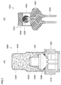
- FIG. 1 is a schematic cross-sectional view of a safety device 100 for an aircraft according to the first embodiment.
- the safety device 100 for a flight vehicle includes an actuator 88 as an injection device and a paraglider 10 as a deployed object.
- the actuator 88 includes an igniter 84 having a cup-shaped case 85 for containing an igniter (not shown), a piston 81 having a recess 82 and a piston head 83 integrally formed with the recess 82, and a piston 81. It has a bottomed cylindrical housing 86 which accommodates and regulates the direction of propulsion of the piston 81.
- the paraglider 10 is housed in the housing 86 in a non-deployed state and disposed on the piston head 83. By propelling the piston 81 in such a configuration, the paraglider 10 can be directly extruded and deployed.
- the open end of the housing 86 is closed by a lid 87 in the initial state, and the lid 87 is configured to be released from the open end by the extrusion of the paraglider 10.
- an abnormality detection unit such as an acceleration sensor
- the piston 81 is propelled by the gas pressure generated based on the ignition operation of the igniter 84.
- the paraglider 10 is directly pushed out by the propulsive force of the piston 81.
- the paraglider 10 is connected to the housing 86 via a connecting member (line), and after deployment, the flying object 30 described later is suspended via the connecting member (line). It is configured to be able to
- the flying body 30 includes a body 31, a safety device 100 for a flying body attached to the body 31, and one or more propulsion mechanisms (for example, a propeller etc.) 32 provided on the body 31 and propelling the body 31. , And a plurality of legs 33 provided at the lower part of the airframe 31.
- FIG. 3 shows the paraglider 10 after deployment.
- the paraglider 10 includes a canopy (wing-like member) 40.
- the canopy 40 includes an upper cross 41, a lower cross 42, a rib 43, and a side cross 70.
- a reinforced cloth made of chemical fiber such as nylon or polyester is used.
- FIG. 4 illustrates the vehicle 30 in a state after the paraglider 10 has been deployed.
- the upper cloth 41 and the lower cloth 42, together with the side cloths 70 on both sides, have their outer edges joined by stitching or the like so that a predetermined space is formed therebetween.
- the ribs 43 vertically divide a predetermined space between the upper cross 41 and the lower cross 42 to form a plurality of cells (air chambers) 44, A plurality of the upper cross 41 and the lower cross 42 are provided at predetermined intervals.
- each of the cells 44 is for retaining the wing shape of the canopy 40 by drawing air when the canopy 40 is deployed.
- air flow holes 45, 46, 47, 48 are provided in each of the ribs 43, and the air in the cell 44 is made of the canopy 40 by these internal air flow holes 45, 46, 47, 48. It can move to the left and right.
- An air intake (air intake) 49 is provided at the front portion (front edge) of each cell 44, and air can be taken into each cell 44. In FIG. 3, only the inside of the cell 44 on the front side of the drawing is shown transparently.
- An elongated bag-like member 50 which can be folded or wound is inserted into the internal air flow hole 45.
- the term “foldable” as used herein includes, for example, being foldable like a bellows, being foldable several times and being able to be folded in a superimposed manner.
- One end 51 (the front side in the drawing of FIG. 3) of the bag-like member 50 is joined to the side cross 70 on the front side in the drawing of FIG. 3 by stitching or the like.
- the bag-like member 50 is extended along the inside of the upper cross 41 from the insertion portion into the internal air flow hole 45 to the other end of the canopy 40 (the back side in FIG. 3) (more preferable Are joined to the upper cross 41 or the lower cross 42 by stitching or the like).
- the bag-like member 50 a reinforced cloth similar to the upper cloth 41 or the like can be used, but in order to protect the cloth from the heat of the gas generated by the gas generator 60, a particularly heat resistant material is used. It is preferable to use one having a heat resistant surface coating on the inner surface. In addition, since the bag-like member 50 needs to withstand rapid expansion due to the inflow of gas, it is preferable that the bag-like member 50 has a strength that can withstand the pressure of the generated gas.
- the base cloth of the bag-like member 50 includes, for example, nylon 6, nylon 66, nylon 12, nylon 46, nylon 56, nylon 610, copolyamide of nylon 6 and nylon 66, and polyalkylene 6 for nylon 6.
- Copolymerized polyamides obtained by copolymerizing glycol, dicarboxylic acid, amine and the like, polyester resins such as polyethylene terephthalate, polybutylene terephthalate and polytrimethylene terephthalate, and polyolefin resins such as polyacrylic resin and polypropylene can be used.
- polyamide 66 excellent in impact resistance and heat resistance can be suitably used particularly as a base cloth of the bag-like member 50.
- silicone resin for example, silicone resin, polyurethane resin, polyacrylic resin, polyamide resin, polyester resin, polyolefin resin
- various resins such as fluorocarbon resin, and various rubbers such as silicone rubber, chloroprene rubber and chlorosulfonated polyethylene rubber
- silicone resin By using a silicone resin, not only heat resistance, but also cold resistance, flame retardancy and air barrier properties can be enhanced.
- silicone resin dimethyl silicone resin, methyl vinyl silicone resin, methylphenyl silicone resin, fluoro silicone resin can be used.
- the coating layer preferably further contains a flame retardant compound.
- halogen compounds containing bromine, chlorine and the like especially halogenated cycloalkanes
- platinum compounds antimony oxides, copper oxide, copper oxides, titanium oxides, phosphorus compounds, thiourea compounds, carbon, cerium, silicon oxides, etc.
- a halogen compound, a platinum compound, copper oxide, titanium oxide and carbon it is more preferable to use a halogen compound, a platinum compound, copper oxide, titanium oxide and carbon.
- the coating layer is preferably selected in accordance with the material of the yarn to be used as the base fabric, and is preferably made of a material that adheres tightly to the warp and weft.
- the coating layer is preferably a polyurethane resin or a polyacrylic resin.
- a hole (not shown) capable of discharging excess air to the outside of the canopy 40 in order to adjust the internal pressure of the bag-like member 50 is provided.
- the bag-like member 50 it is preferable to use one having a tube-like (tubular or tubular) shape having an internal space when expanded by the gas flowing into the inside.
- a gas generator 60 capable of releasing gas and pressurizing the inside of the bag-like member 50 is provided.
- the gas generator 60 has an igniter inside, and is a pyrotechnic type further having a transfer agent, a gas generator, a filter and the like as required. Further, the gas generator 60 is connected to an electric circuit in which a power supply 61 and a switch 62 are connected in series. This electric circuit is provided inside the cell 44 on the front side of the paper surface in FIG.
- the gas generating agent it is preferable to use a non-azide gas generating agent, and in general, the gas generating agent is formed as a molded body containing a fuel, an oxidant and an additive.
- a fuel for example, a triazole derivative, a tetrazole derivative, a guanidine derivative, an azodicarbonamide derivative, a hydrazine derivative or the like or a combination thereof is used.
- nitroguanidine, guanidine nitrate, cyanoguanidine, 5-aminotetrazole and the like are suitably used.
- the oxidizing agent is selected from, for example, basic nitrates such as basic copper nitrate, perchlorates such as ammonium perchlorate and potassium perchlorate, or alkali metals, alkaline earth metals, transition metals and ammonia. Nitrates and the like containing the selected cations are used. As the nitrate, for example, sodium nitrate, potassium nitrate and the like are suitably used. Moreover, a binder, a slag formation agent, a combustion regulator etc. are mentioned as an additive.
- a metal salt of carboxymethyl cellulose for example, a metal salt of carboxymethyl cellulose, an organic binder such as stearate, or an inorganic binder such as synthetic hydrotalcite or acid clay can be suitably used.
- an organic binder such as stearate, or an inorganic binder such as synthetic hydrotalcite or acid clay
- a slag forming agent silicon nitride, silica, acid clay etc. can be suitably used.
- metal oxides, ferrosilicon, activated carbon, graphite and the like can be suitably used.
- a single base powder based on nitrocellulose, a double base powder, or a triple base powder may be used.
- the shape of the gas generating agent molded body there are various shapes such as granular shape such as granular shape, pellet shape and cylindrical shape, and disk shape.
- granular shape such as granular shape, pellet shape and cylindrical shape, and disk shape.
- cylindrical thing the thing (for example, single-hole cylinder shape or porous cylinder shape etc.) which has a through-hole in the inside of a molded object is also utilized.
- the switch 62 has a positive electrode plate and a negative electrode plate, and has a configuration in which an insulator 62a is sandwiched between the positive electrode plate and the negative electrode plate.
- the insulator 62a is connected to the airframe 31, the leg 33, the safety device 100 for an aircraft, or a projectile or the like via a string member (not shown) as a switch control unit. Accordingly, when the paraglider 10 is ejected, the insulator 62a is configured to be pulled out from between the positive electrode plate and the negative electrode plate of the switch 62 by the generation of tension in the string member.
- the switch 62 is turned on, current flows from the power supply to the electric circuit, and the igniter is ignited thereby.
- the gas generator 60 operates.
- the length is adjustable so that the string member mentioned above is comprised, It is comprised so that the timing which supplies with electricity to an igniter can be adjusted suitably.
- the gas generator 60 may be communicably connected to an external control unit.
- the power on / off switch is controlled by the electric signal transmitted from the control unit, instead of the above-mentioned cord member.
- an IC (Integrated Circuit) timer may be used to turn on the power after an arbitrary time has elapsed.
- a delaying agent for delaying the ignition of the ignition agent for a predetermined time
- a delaying agent for delaying the ignition of the ignition agent for a predetermined time
- an electrical delay ignition intention
- the operation timing of the gas generator 60 may be adjusted by retarded ignition.
- a resistor for example, a bridge wire made of a nichrome wire or the like
- converting the transmitted electric energy into heat energy and an electricity for energizing the resistor There is a terminal provided with a terminal.
- a hybrid type or stored type gas generator in which a seal plate in a small gas cylinder is cleaved by a pyrotechnic igniter and the internal gas is discharged to the outside. It is also good.
- noncombustible gas such as argon, helium, nitrogen, carbon dioxide or a mixture thereof can be used.
- a gas generator may be equipped with a heating element made of a gas generating composition, a thermite composition or the like.
- the deployment timing of the paraglider 10 can be appropriately and accurately controlled by delaying the ignition of the igniter for a predetermined time or the like.
- the operation delay mechanism one that delays the timing of energization of the gas generator 60 from the time when injection of the paraglider 10 by the actuator 88 is started corresponds to the operation delay mechanism.
- what delays the timing to start the combustion of the ignition agent by using the delay medicine is the same as the timing when the injection of the paraglider 10 by the actuator 88 is started.
- the gas is released from the gas generator 60 at a timing delayed from when the injection of the paraglider 10 by the actuator 88 is started.
- the ejection of the paraglider 10 is completed, and the paraglider 10 is deployed after the paraglider 10 is separated to such an extent that the propulsion mechanism 32 provided on the flying object 30 and other portions do not interfere As a result, the injection of the paraglider 10 will not be impeded, and the paraglider 10 can be reliably deployed.
- deployment shown to FIG. 3 and FIG. 4 is comprised so that it can fold by one of the following three methods.
- the first method is a method in which the canopy 40 is wound while removing air in each cell 44 such that the portion on the back side of the paper surface of FIG. 3 of the canopy 40 is inward.
- the second method is to collapse the canopy 40 in the longitudinal direction by squeezing the cells 44 sequentially from the back side of the paper surface of the canopy 40 in FIG. 3 so as to squeeze the air in the cells 44. It is a method.
- the third method is a method of folding the canopy 40 in an overlapping manner by folding the canopy 40 in order while squeezing the cells 44 sequentially from the back side of the paper surface of the canopy 40 in FIG. .
- the canopy 40 rolled up or folded up by any of the above-mentioned methods operates the gas generator 60 after the paraglider 10 is ejected into the air (more precisely, the gas is emitted after the paraglider 10 is ejected into the air) The gas is released from the generator 60).
- the gas is released from the gas generator 60 after a predetermined time elapses from the time when the injection of the paraglider 10 by the actuator 88 is started, and the gas flows into the bag-like member 50, thereby forming a bag
- the member 50 expands and the folded bag-like member 50 starts to expand.
- the cell 44 in the canopy 40 of the part in which the gas generator 60 is provided inside begins to expand.
- the inside of the cell 44 has a negative pressure, external air is taken in from the air intake 49, and the cell 44 on the front side of the paper surface in FIG. 3 continues to expand to a predetermined shape.
- the gas generated in the gas generator 60 further flows into the bag-like member 50, and the bag-like member 50 further expands and stretches, thereby sequentially from the cell 44 in which the gas generator 60 is provided.
- the adjacent cells 44 expand continuously while taking in the external air from each air intake 49, and finally the cells 44 on the back side of the paper surface in FIG. 3 expand.
- the shape like the canopy 40 shown in FIG. 3 is formed early from the time of operation of the gas generator 60.
- the disposition position of the gas generator 60 be in the vicinity of the center of the bag-like member 50 disposed along the longitudinal direction of the paraglider 10.
- the bag-like member 50 is developed based on the same principle as when a person blows back the toy, and accordingly the canopy 40 is also It will expand in the same manner.
- the paraglider 10 After being deployed as described above, the paraglider 10, as shown in FIG. 4, includes a plurality of lines 80 connected to both sides of the canopy 40 and the lower portion of the canopy 40 to provide the flight vehicle safety apparatus 100 It will be in the state connected with the main part.
- each line 80 can be tensioned or loosened by winding and feeding each line 80 using a motor (not shown) separately provided for the safety device 100 for a flight vehicle.
- the traveling direction of the paraglider 10 can also be operated by giving an instruction to control the motor (not shown) appropriately by remote control or the like.
- the present embodiment it is possible to simplify the construction and shorten the deployment time of the paraglider 10, and also for flight vehicle safety in which the paraglider 10 can be deployed with a very small amount of gas than conventional. It can be an apparatus and an aircraft equipped with the same.
- the gas generator 60 is a pyrotechnic type having an igniter inside, the gas can be generated instantaneously, and the deployment speed of the paraglider 10 can be increased.
- the bag-like member 50 is illustrated as having a single long thin tube, but the present invention is not limited to this.
- the bag-like member may have a plurality of tubular portions formed radially or in a grid so that the interiors communicate with each other. Since the plurality of tubular sections can be expanded by the gas generated by the gas generator by extending the plurality of tubular sections inside the canopy, the paraglider in a rolled up or folded up state Can be more easily deployed.
- the bag-like member 50 is configured to be inflated by one gas generator is illustrated, but the bag-like member 50 is configured to be inflated by a plurality of gas generators It is also good.
- the capacity of the bag-like member also increases accordingly, and the expansion speed of the paraglider is achieved by inflating it with a plurality of gas generators You can speed up
- a pyrotechnic type gas generators of other styles, such as a cylinder type, may be used.
- a micro gas generator MMG having a structure such that a gas jet port is formed by an increase in internal pressure due to gas generated at the time of operation Or squibs may be used instead of the gas generator described above.
- FIG. 5 (A) and FIG. 5 (B) are figures which show the specific structural example of the gas generator 60.
- FIG. 5A shows an example of one configuration of the micro gas generator when the above-described micro gas generator is used as the gas generator 60
- FIG. 5B the gas generator 60 is described above.
- One configuration example of the squib in the case of using the squib is shown.
- the micro gas generator 1000 has a holder 1010, a squib 1020, a cup body 1030, a gas generating agent 1040, a combustion control cover 1050, and a seal member 1060.
- the squib 1020 and the cup body 1030 are held by a holder 1010, and the space surrounded by the holder 1010, the squib 1020 and the cup body 1030 is filled with a gas generating agent 1040.
- the squib 1020 is, for example, the one shown in FIG. 5B described later.
- the pair of terminal pins 1022 of the squib 1020 is disposed to pass through the holder 1010, and the squib body 1021 connected to the pair of terminal pins 1022 is disposed to face the space inside the cup body 1030. ing.
- the squib body 1021 is covered with a combustion control cover 1050 for providing directivity to heat particles generated in the squib body 1021 when the squib 1020 is in operation.
- a sealing member 1060 made of, for example, an O-ring or the like for sealing the space filled with the gas generating agent 1040 from the outside is interposed.
- the activation of the squib 1020 generates heat particles in the squib main body 1021, and the generated heat particles ignites and burns the gas generating agent 1040. .
- the gas pressure generated by the combustion of the gas generating agent 1040 causes the cup 1030 to break, and the generated gas is released to the outside accordingly, and the released gas serves to expand the bag-like member 50. It will be done.
- the squib 1020 has a squib main body 1021 and a pair of terminal pins 1022.
- the squib body 1021 mainly includes a base portion 1023, a cup-shaped member 1024, an ignition ball 1025 containing an ignition agent, and a gas generating agent 1026.
- the cup-shaped member 1024 is held by the base portion 1023, and the ignition ball 1025 and the gas generating agent 1026 are accommodated in a space surrounded by the base portion 1023 and the cup-shaped member 1024.
- the pair of terminal pins 1022 are disposed so as to pass through the base portion 1023, and are held by the base portion 1023.
- the tip of each of the pair of terminal pins 1022 is disposed to face the space inside the cup-shaped member 1024.
- the tip of each of the pair of terminal pins 1022 disposed to face the space inside the cup-shaped member 1024 is connected via a bridge wire (resistor) not shown.
- the ignition ball 1025 is configured to cover the tip of each of the pair of terminal pins 1022 and the bridge wire connecting them, and the gas generating agent 1026 is in partial contact with the ignition ball 1025. In the space on the bottom side of the cup-shaped member 1024.
- the squib 1020 By using the squib 1020 having such a configuration, when the bridge wire is energized through the pair of terminal pins 1022, heat is generated in the bridge wire, and the heat ignites the ignition ball 1025 by the heat, and the ignition is performed.
- the gas generating agent 1026 is further ignited by the ignited ball 1025.
- the gas pressure generated by the combustion of the gas generating agent 1026 causes the cup-shaped member 1024 to break, and the generated gas is released to the outside accordingly, and the released gas is used for the expansion of the bag-like member 50. It will be provided.
- FIG. 6 is a schematic front view showing a state after deployment of the parachute 110 of the aircraft 130 provided with the safety device 200 for aircraft according to the first modification
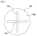
- FIG. 7 is a schematic view of the parachute 110 shown in FIG. It is a schematic diagram which showed the structure of the inner side after expansion
- the safety device 200 for a flight vehicle according to the present modification has substantially the same configuration as the safety device 100 for a flight vehicle according to the first embodiment, but instead of the paraglider 10, a parachute is used. It has 110.
- the parachute 110 includes an umbrella 140 which can be folded in a housing 186, a bag-like member 150 provided on the inner side surface 140 a of the umbrella 140, and a bag-like member A gas generator 160 capable of supplying a gas to the inside of 150 is provided.
- the bag-like member 150 and the gas generator 160 may be provided on the outer surface of the umbrella body 140.
- the umbrella body 140 can be made of the same material as the canopy in the first embodiment, and can reduce the falling speed of the attached object (here, the flying object 130), a so-called parachute It is one of the parts to constitute. Also, the umbrella 140 is connected to the housing 186 via the line 180.
- the bag-like member 150 is, similarly to the umbrella 140, inflatablely affixed or sewn to the inner side surface 140a of the umbrella 140 so that it can be folded before deployment.
- the bag-like member 150 is configured to expand and form a cruciform tubular (tubular or tubular) shape. It is done.
- the parachute 110 is configured to expand as the folded bag-like member 150 expands.
- shape after expansion of bag-like member 150 was made into the shape of a cross
- shape after expansion does not only this but a plurality of tube-like parts from the center further, for example May be configured to extend radially, or may be formed in a lattice.
- the gas generator 160 is the same as the gas generator 60 in the first embodiment described above, and is provided near the center of the bag-like member 150. Further, although not shown, the gas generator 160 is connected to the same electric circuit as that of the first embodiment described above also in this modification.
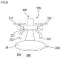
- FIG. 8 is a schematic front view showing a state after the air bag 311 is deployed, of the flying object 230 provided with the safety device 300 for a flying object according to the second embodiment.
- the configuration in FIG. 8 to which the same lower two-digit code as the lower two-digit code attached to the configuration shown in FIG. 4 is basically the same as the configuration described in FIG. Because there is a case, the description may be omitted.
- the flying object 230 is provided with an air bag device 310 that inflates the air bag 311 by the gas pressure generated based on the operation of a gas generator (not shown).
- the air bag device 310 is provided at the lower part of the airframe 231 in the normal posture such that the air bag device 310 is opposed to the main body of the aircraft safety device 300 provided above the airframe 231 in the normal posture with the airframe 231 interposed therebetween. ing.
- a bag-like member 250 similar to the bag-like member 150 in the first modification and a gas generator 260 capable of supplying gas to the inside of the bag-like member 250 are provided on the inner side of the lower part of the air bag 311.
- the expanded shape of the bag-like member 250 is the same as that of the bag-like member 150 in the first modified example, and the shape may be suitably selected such as being radial or latticed. You can change it.
- the bag-like member 250 and the gas generator 260 may be provided on the outer side of the air bag 311.
- the material of the air bag 311 and the material of the bag-like member 250 are the same as the materials of the paraglider 10 and the bag-like member 50 in the first embodiment.
- the gas generator 260 is the same as the gas generator 60 in the first embodiment described above, and is provided near the center of the bag-like member 250. Although not shown, the gas generator 260 is also connected to the same electric circuit as that of the first embodiment described above in this embodiment.
- the flight vehicle safety apparatus 300 having such a configuration can provide the following operation and effects.
- the gas generator 260 can be operated to inflate the bag-like member 250 after the normal operation of the airbag device 310 is started.
- the portion of the air bag 311 provided with the bag-like member 250 can be deployed more quickly than the other portions.
- the expansion force of the air bag 311 due to the expansion of the bag-like member 250 can be added to the expansion force of the air bag 311 in the original air bag device 310. Therefore, the structure is simple and the deployment time of the air bag 311 can be shortened, and the deployment of the air bag 311 becomes possible with a very small amount of gas compared to the prior art.
- the injection of the air bag 311 is completed, and the air bag 311 is released to such an extent that the air bag 311 does not interfere with the legs 233 provided on the flying object 230 or other parts. Since the deployment of the air bag 311 is started, the injection of the air bag 311 is not impeded, and the air bag 311 can be reliably deployed.
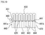
- FIG. 9 is a schematic front view showing a state of an aircraft 430 provided with a safety device 400 for a flight according to a second modification after the paraglider 410 is deployed
- FIG. 10 is a paraglider 410 shown in FIG. It is a schematic diagram which shows an example of the accommodation state of.
- the configuration to which the same lower two-digit code as the lower two-digit code attached to the configuration shown in FIG. 4 is applied is basically the same as the configuration described in FIG. The description may be omitted because it is the same.
- the safety device 400 for a flight vehicle can supply gas to the inside of the paraglider 410, the inflatable elongated bag-like member 450, and the bag-like member 450.
- a possible gas generator 460 and an actuator (not shown) similar to the actuator 88 in the first embodiment are provided.
- the aircraft safety device 400 is mounted on the aircraft 430.
- the paraglider 410 is provided with a canopy 440 which is a wing-like member, and is housed in a folded state in a housing 486 of the flying object 430.
- the canopy 440 of the paraglider 410 includes an upper cross 441, a lower cross 442, a rib 443, and a side cross 470, and is at least one of the three methods as in the first embodiment. It can be folded, and in FIG. 10, the air in each cell 444 is removed and folded.
- the bag-like member 450 is configured to have a tube-like (tubular or tubular) shape having an internal space when expanded by the gas flowing into the inside, and is provided on the top of the canopy 440 . More specifically, as shown in FIG. 10, both ends of the bag-like member 450 are connected by sewing or the like to the left and right ends 441a and 441b of the upper cross 441 of the canopy 440 ( Or bonded).
- the bag-like member 450 and the canopy 440 are bonded at only two places of the left and right end portions 441a and 441b of the upper cross 441.
- the bonding pattern may be used, but not limited to this, for example, in addition to the left and right end portions 441a and 441b of the upper cross 441, a plurality of bonding portions 420 (see FIG. It is good also as an adhesion pattern which provides and adheres (refer circle part).
- the bonding portion 420 may be provided on the plurality of ribs 443 of the canopy 440.
- the bag-like member 450 can be stored in a folded or wound state in the housing 486 of the flying object 430, and one end 451 of the bag-like member 450 is connected to the gas generator 460. It is done. In FIG. 10, the bag-like member 450 is shown in a state of being folded in a bellows-like manner.
- the gas generator 460 is the same as the gas generator 60 in the first embodiment described above, and is provided at one end 451 of the bag-like member 450. Further, although not shown, the gas generator 460 is also connected to the same electric circuit as that of the first embodiment described above in this modification.
- the paraglider 410 and the bag-like member 450 are housed in the housing 486 in a folded state, respectively, and operated by the actuator in the housing 486.
- the gas generator 460 is operated after being injected into the air, the folded bag-like member 450 is expanded and the canopy 440 of the paraglider 410 is forcibly and instantaneously deployed.
- each cell 444 since each cell 444 has a negative pressure, each cell 444 expands while taking in external air from the plurality of air intakes 449, and as shown in FIG. 9, the paraglider 410 is expanded. It will be As a result, the bag-like member 450 is maintained in a tube-like state in which the gas is filled inside, so that the bag-like member 450 functions like a framework of the canopy 440, whereby the wing shape is maintained. As a result, it becomes possible for the flying object 430 to fly stably.
- the present modification it is possible to simplify the structure and shorten the deployment time of the paraglider 410, and to provide a safety device 400 for an aircraft for which the paraglider 410 can be deployed with a very small amount of gas than before. be able to. Further, in the present modification, the bag-like member 450 retains the wing-like shape of the paraglider 410, so that flight stability can be improved as compared to the prior art.
- bag-like member 450 was made into a single elongate tube shape, it is not limited to this, even if it changes the shape of bag-like member 450 suitably Good.
- the bag-like member may have a plurality of tubular portions formed radially or in a grid so that the interiors communicate with each other.
- the bag-like member 450 may be provided outside the lower cross 442 of the canopy 440.
- the stiffness (strength) of the bag-like member 450 during deployment may be greater than the stiffness (strength) of the canopy 440.
- the arrangement position of the gas generator 460 may be near the center of the bag-like member 450.
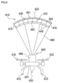
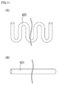
- FIG. 11 is a view showing a frame member 421 as a shape recoverable member provided in the safety device for a flying object according to the third modification, wherein (A) is a schematic view showing the storage state of the frame member 421. (B) is a schematic diagram which shows the expansion
- the framework member 421 is formed of an elongated rod-like member (that is, an elastic member) capable of elastic deformation, and is made of, for example, rubber, metal, etc. It consists of bars.
- the frame member 421 is a rubber bar, as shown in FIG. 11A, the frame member 421 is bent and a string member (not shown) having a locking tool such as a hook or the like. In the locked state bound by the inside of the housing of the safety device for a flying object. Further, at least a part of the framework member 421 is adhered to the outside of the deployable body.
- the gas generator for lock release is provided in the exterior of a to-be-deployed body.
- the gas generator is connected to the frame member 421, and is configured to be able to release the locked state of the string member with the frame member 421 by the gas and heat generated at the time of operation.
- the locking state of the string member with respect to the frame member 421 is released by activating the gas generator for releasing locking after the deployed body is injected into the air. Since elastic restoring force is generated in the frame member 421, the frame member 421 instantly becomes in the stretched state shown in FIG. 11 (B). With the extension of the frame member 421, it is possible to deploy the object to be deployed forcibly and instantaneously.
- the frame member 421 can maintain the deployed shape of the deployable body, deformation of the deployable body due to strong wind and the like can be suppressed, and the flight stability is improved compared to the prior art. It will be.
- the storage state and the extension state of the framework member 421 are not limited to a specific shape, and may be any shape as long as the expanded shape of the object to be deployed can be held.
- a locking member can maintain the state where the frame member 421 was bent. If it is, it may be anything.
- the frame member is bent in a bent state using an annular band as a locking member and is housed in the housing, and the band is detached by the operation of the gas generator for releasing the lock (generated heat The band may be melted and cut, or the generated gas may blow off and remove the band, etc., so that the locking with the frame member is released.
- the housing of the safety device for a flying object is used as a locking member of a framework member, and the framework member is folded and stored in the housing together with the deployable body as shown in FIG.
- the locked state of the housing with respect to the frame member may be released.
- shape memory alloy made of shape memory alloy as a shape memory member which has a shape memory characteristic It can also be constituted by a bar of
- the shape memory is a property of being restored to the original shape (initial shape) before deformation by heating the deformed metal to a certain temperature or more.
- the frame member made of shape memory alloy bar is adhered to the outside of the object to be deployed, and is stored in a bent state in a housing provided with an actuator as an injection device. . Then, the frame member is heated by the operation of the gas generator provided in the actuator and ejected from the housing to be restored to the original shape of the rod, and in accordance with this, the object to be deployed is It will be deployed forcibly and instantaneously. Also in this case, since the frame member holds the deployed shape of the object to be deployed, flight stability can be improved more than before.
- the total weight of the aircraft including the safety device for the aircraft is m [kg]
- the speed of the aircraft at the time of fall is In the case of v [m / s]
- the speed of the flying object is 0.3 m / s to 11.7 m / s according to the total weight m. It is necessary to decelerate the aircraft early so that:
- the deployed object such as parachute or paraglider can be deployed early. It is important to design the system so that the above deceleration can be realized.
- the time from the time of injection by the injection device to the start of deployment of the deployable object is It is preferably within 10 seconds, more preferably within 8 seconds, still more preferably within 5 seconds, and in some cases within 3 seconds or within 1 second. It should be noted that the time from the start of ejection of the deployable to the completion of deployment varies depending on the length of the connecting member (ie line or cord) connecting the deployable to the flight, the total weight of the flight, etc. It is necessary to appropriately adjust the timing of the start of deployment of the object to be deployed according to these.
- a deployable object such as a parachute or paraglider is wound up or folded up.
- the explanation is made by exemplifying the case where it is configured to deploy at one time from the undeployed state, but when configured as such, the impact applied to the flying object at the time of deployment of the deployable body is large. There is also concern that it will become too much.
- the deployable body can be deployed stepwise, it is possible to reduce the impact applied to the flight body. From the viewpoint of achieving both the alleviation of the impact applied to the flying object and the simplification of the device configuration, it is preferable that the deployed object be configured to be deployed in two or three stages.
- the parachute or paraglider deployment apparatus is provided on the parachute or paraglider, the parachute or the paraglider ejection apparatus, the parachute or the paraglider, and is wound or folded.
- the parachute or the paraglider which can be expanded into a tubular form from the folded or folded state and expanded in the tubular form, the parachute or the paraglider in a rolled up or folded up state; And a gas generator capable of causing the gas generated inside of the bag-like member to flow in and expanding the bag-like member at the time of operation.
- the parachute or paraglider deployment apparatus is connected to the parachute or paraglider, the parachute or the paraglider ejection apparatus, and the parachute or the paraglider, and the parachute or the paraglider It is rolled up or folded separately from the paraglider, and can be expanded into a tubular form from the rolled up or folded up state, and when expanded into the tubular form, it can be rolled up or folded up.
- a bag-like member capable of expanding the parachute or paraglider in a folded state, and a gas generator capable of causing the gas generated inside the bag-like member to flow when in operation to inflate the bag-like member May be provided.
- the structure is simple and the deployment time of the parachute or paraglider can be shortened, and the parachute or paraglider can be deployed with a very small amount of gas than conventional. Or can provide a paraglider deployment device.
- the gas generator referred to here is divided into an explosive type and a non-explosive type, and the explosive type has an igniter.
- non-explosives there may be mentioned those in which gas is generated by mixing, or those in which gas is enclosed in a cylinder.
- the bag-like member after deployment as a frame (beam) the deployed shape of the parachute or paraglider can be maintained, and therefore the flight stability can be improved as compared with the conventional deployment device.
- the parachute often has an umbrella-like base shape, is connected to the object to be protected by a cord, and is decelerated using air resistance.
- the parachute includes an umbrella, a single umbrella, a plurality of umbrellas having the same shape and a plurality of umbrellas having different shapes. Furthermore, there are parachutes in which the center of the umbrella is closed or in which the hole called "spillhole” is opened at the center of the umbrella. These are appropriately selected in order to reduce the influence of disturbances such as shock reduction, settlement speed, and wind at the time of parachute deployment.
- the paraglider generally has a wing shape with an aspect ratio of 1 or more, and a steering cord called a break cord is connected from the left and right ends of the wing.
- a steering cord called a break cord
- various stresses applied to the wing cross section can be changed, and as a result, gliding, turning and rapid deceleration can be performed. For this reason, the paraglider can perform gliding, turning, and decelerating that can not be done with the parachute.
- Similar in construction there are also logaro-type paragliders.
- paragliders with air intake are the mainstream, but some do not.
- a paraglider with air intake is more preferable for stable flight.
- a paraglider that can be propulsively driven by attaching a propulsion device such as a propeller may be used.
- the parachute or paraglider deployment apparatus is provided on the parachute or paraglider, the parachute or the paraglider ejection apparatus, the parachute or the paraglider, together with the parachute or the paraglider. It is rolled up or folded up, and after injection of the parachute or paraglider by the injection device, it is restored from the wound up state or folded up state to the initial state shape by elastic force or shape memory by shape memory And a shape recoverable member capable of deploying the parachute or the paraglider in a rolled up or folded up state when restored to the shape in the initial state. Also good
- the parachute or paraglider deployment apparatus is connected to the parachute or paraglider, the parachute or the paraglider ejection apparatus, and the parachute or the paraglider, and the parachute Or separately from the paraglider, it is wound or folded, and after ejection of the parachute or the paraglider by the ejection device, shape restoration force by elastic force or shape memory from the wound state or the folded state
- the parachute or paraglider which can be restored to the shape of the initial state, and is restored to the shape of the initial state, in the wound state or the folded state; I have It may be.
- the parachute or paraglider deployment apparatus is capable of locking the shape restorable member in a wound state or a folded state, and the application of external force or energy is effective to It is preferable that a locking member capable of releasing the locking is provided, and the shape recoverable member is an elastic member.
- a parachute or a paraglider can be expand
- the parachute or paraglider deployment apparatus of the above (5) uses the energy of heat generated at the time of operation to release the locking by the locking member, or uses the pressure of the gas generated at the time of operation
- a gas generator capable of releasing the locking of the locking member is provided.
- the parachute or paraglider deployment apparatus of (5) may include a gas generator provided to release the locking by the locking member.
- the parachute or paraglider deployment apparatus of the above (5) includes a gas generator capable of conducting heat generated at the time of operation to the shape restorable member, the shape restoration The member may be restored to the memorized shape by the conduction of the heat.
- the shape restorable member can be locked with a simple configuration, and the locking of the shape restorable member by the locking member can be easily released. Can.
- the locking by the locking member can be released more accurately.
- the gas generator controls a control mechanism to operate after the operation of the injection device. It is preferable to have.
- the deployment timing of the parachute or paraglider can be appropriately controlled.
- the gas generator be a pyrotechnic type having an igniter inside.
- gas can be generated instantaneously.
- a non-explosive gas cylinder type gas generator is used, a sharp member such as a needle and a compressed spring are connected, and the sharp member is blown using a spring force to seal the cylinder. It will collide with the plate to release the gas.
- a servomotor is usually used to release the compression force of the spring, but the gas generation rate of the gas cylinder type gas generator is It is greatly inferior to the bowl.
- a high strength locking member is required, which increases the cost and weight. Therefore, the use of a gas generator having a pyrotechnic igniter makes it possible to reduce the size and weight of a parachute or paraglider deployment apparatus, as compared to a non-explosive gas cylinder type.
- the control mechanism is an ignition delay mechanism that delays the ignition of the igniter for a predetermined time.
- ignition delay means that the gas is released from the gas generator at a timing delayed from the timing at which the parachute or paraglider is injected, and the parachute or paraglider is developed.
- the parachute or paraglider can be deployed. Note that if the parachute or paraglider is simultaneously ejected and deployed, the parachute or paraglider may start to be deployed in the ejection device and may interfere with the ejection. It is also conceivable that the parachute or paraglider may be entangled in a propulsion device or other part such as an aircraft to which the deployment device is attached when the parachute or paraglider is simultaneously ejected and deployed.
- the parachute or paraglider when the parachute or paraglider has been released from the gas generator, the parachute or paraglider has been released from the inside of the injection device to such an extent that the parachute or paraglider does not interfere with the propulsion device or other part provided in the aircraft. It is preferable to appropriately set a delay time (a time from injection of a parachute or paraglider to development thereof) by the ignition delay mechanism so that gas is released.
- the igniter internally includes an ignition agent and ignition means capable of generating flame energy for igniting the ignition agent, Preferably, an ignition delay mechanism is provided between the ignition agent and the ignition means, and provided with a delay agent for transmitting the flame energy of the ignition means with a time difference to the ignition agent.
- an ignition delay mechanism is provided between the ignition agent and the ignition means, and provided with a delay agent for transmitting the flame energy of the ignition means with a time difference to the ignition agent.
- a composition that serves to convert electric energy input to the igniter into flame energy inside the igniter, retain the flame energy, and transmit a time difference to the next ignition medicine.
- this pharmaceutical agent comprises an oxidizing agent selected from the group consisting of oxides and peroxides, an elemental metal or a metal nitride, a metal silicon compound, a metal fluorine compound, a metal sulfide, and a metal phosphorus. It is composed of a reducing agent at least one or more selected from compounds and the like.
- the ignition delay mechanism includes an electric circuit having a power supply and a switch of the power supply, and a control unit that controls the switch. Is preferred.
- the ignition delay mechanism includes a power source, a positive electrode plate, a negative electrode plate facing the positive electrode plate, and the positive electrode plate and the negative electrode plate removably. And a switch capable of changing the power supply from the off state to the on state, one end thereof being connected to the insulator, and the other end being the main body of the injection device or the deployment And a cord member connected to a predetermined portion of the fixing destination of the device, wherein the deployment device pulls the insulator by the cord member when the parachute or the paraglider is ejected. It may be removed from between the positive electrode plate and the negative electrode plate, the positive electrode plate and the negative electrode plate may be in contact, and the power may be changed from off to on.
- the deployment timing of the parachute or paraglider can be controlled appropriately and accurately. Without these configurations, it is necessary to hold on the parachute or paraglider side the lead wire necessary to transmit the activation signal even during injection in order to operate at a delayed timing to the deployment device, and the component weight There is a concern about the increase and disconnection of the lead wire. Furthermore, units for controlling the injection device and the expansion device are respectively required, resulting in complication and increased weight.
- the length of the cord member is adjustable in the ignition delay mechanism.
- the timing which supplies with electricity to the igniter in a gas generator can be adjusted suitably.
- the bag-like member has a plurality of tubular portions formed radially or in a lattice so that the insides communicate with each other. Is preferred.
- the plurality of tubular portions provided in a wide range of the parachute or paraglider can be expanded by the gas generated by one or more gas generators, so that winding is possible.
- Parachutes or paragliders in a taken or folded state can be made more easily deployable.
- there are a plurality of gas generators one is more preferable because the structure becomes complicated and the weight and cost increase.
- the bag-like member is provided along the longitudinal direction of the paraglider at the time of deployment.
- the paraglider includes a plurality of air chambers inside, and is provided at the front to correspond to each of the air chambers.
- the wing-like member having a plurality of air inlets, wherein the bag-like member is inside or outside of the wing-like member and in the vicinity of the plurality of air inlets of the paraglider at the time of deployment. It is preferable to extend along the plurality of air intakes.
- the wing-like member of the paraglider in a wound state or a folded state is forcibly and instantaneously deployed
- the pressure inside the wing is negative.
- air can be forced to flow from the plurality of air intake ports into the inside of the wing-like member, so that the wing-like member of the paraglider can be rapidly deployed.
- the airbag deployment device is provided with an airbag and the interior or the exterior of the airbag, and is wound or folded together with the airbag, and wound.
- a bag-like member which can be expanded into a tubular form from a folded or folded state, and when expanded into the tubular form, can deploy the airbag in a rolled up or folded up state;
- a gas generator capable of causing gas generated inside the bag-like member to flow and inflating the bag-like member.
- the airbag deployment device is connected to the airbag and the inside or the outside of the airbag, and is wound or folded separately from the airbag.
- a bag-like member expandable in a tubular form from a rolled up or folded state, and capable of expanding the airbag in a rolled up or folded up state when expanded in the tubular form
- a gas generator capable of causing the gas generated inside of the bag-like member to flow into the bag-like member at the time of operation and inflating the bag-like member.
- this bag-like member When gas is allowed to flow into the above-mentioned rolled or folded bag-like member, this bag-like member easily expands into a tubular (tubular or tubular) shape having an internal space. Be done.
- the structure is simple and the deployment time of the airbag can be shortened, and the deployment of the airbag can be performed with a very small amount of gas than conventional. Become.
- the airbag deployment device is provided with an airbag and the interior or the exterior of the airbag, and is wound or folded together with the airbag, and wound up. It can be restored to the initial state shape by elastic force or shape memory from shape memory from the folded or folded state, and when it is restored to the initial state shape, it is in the rolled up or folded state And a shape recoverable member capable of deploying the air bag.
- the airbag deployment device is connected to the airbag and the inside or the outside of the airbag, and is wound or folded separately from the airbag, It can be restored from the wound state or the folded state to the initial state shape by elastic force or shape memory by shape memory, and when restored to the initial state shape, the wound state or the folding state And a shape recoverable member capable of deploying the airbag in a folded state.
- the airbag can be easily deployed despite the simple structure.
- An airframe according to the present invention includes an airframe, and a parachute or paraglider deployment apparatus of (1) to (17) coupled to the airframe, and / or (11) coupled to the airframe An air bag deployment device, and one or more propulsion mechanisms coupled to the airframe to propel the airframe.
- the parachute or paraglider deployment device of the above (1) to (17) since the parachute or paraglider deployment device of the above (1) to (17) is provided, the construction is simple and the parachute or paraglider deployment time is shortened as described above. It is possible to deploy parachute or paraglider with a much smaller amount of gas than before. Further, in the case of providing the airbag deployment device of the above (18) to (21), the construction is simple and the deployment time of the airbag can be shortened as in the above, The air bag can be deployed with a very small amount of gas.
- the structure is simple and the deployment time of the parachute or paraglider can be shortened, and the parachute or paraglider deployment apparatus capable of deploying the parachute or paraglider with a very small amount of gas compared to the prior art. And, it becomes possible to provide an aircraft including the same. Further, according to the present invention, the deployed shape of the parachute or paraglider can be maintained by using the bag-like member or the shape recoverable member after deployment as a frame (beam), so flight stability can be improved compared to the conventional deployment device. It can be improved.
Abstract
飛行体用安全装置(100)は、被展開体(10)、射出装置、袋状部材(50)およびガス発生器を備える。被展開体(10)は、非展開状態において巻き取られまたは畳まれており、展開状態において揚力および浮力の少なくともいずれかを発生させる。射出装置は、被展開体(10)に連結部材(80)を介して連結されており、非展開状態にある被展開体(10)を空中に向けて射出する。袋状部材(50)は、被展開体(10)に設けられ、非展開状態にある被展開体(10)と共に巻き取られまたは畳まれているかあるいは被展開体(10)と別々に巻き取られまたは畳まれており、少なくともその一部がチューブ状に膨張することにより、非展開状態にある被展開体(10)を展開させる。ガス発生器は、被展開体(10)に設けられ、作動時において発生したガスを袋状部材(50)の内部に流入させることにより、袋状部材(50)を膨張させる。
Description
本発明は、例えばドローン等に代表されるような飛行体および当該飛行体に取付けられる飛行体用安全装置に関する。
従来、各種の飛行体が知られている。飛行体には、旅客機やヘリコプターのような有人航空機に限られず、無人航空機も含まれる。特に近年、自律制御技術および飛行制御技術の発展に伴って、例えばドローンのような無人航空機の産業上における利用が加速しつつある。
ドローンは、例えば複数の回転翼を備えており、これら複数の回転翼を同時にバランスよく回転させることによって飛行する。その際、上昇および下降は、複数の回転翼の回転数を一律に増減させることによって行なわれ、前進および後退は、複数の回転翼の各々の回転数を個別に増減させることで機体を傾けることによって行なわれる。このような無人航空機の利用は、今後世界的に拡大することが見込まれている。
しかしながら、無人航空機の落下事故のリスクが危険視されており、無人航空機の普及の妨げとなっている。こうした落下事故のリスクを低減するために、安全装置としての無人航空機用パラシュート装置が製品化されつつある。このような無人航空機用パラシュート装置は、無人航空機の落下時において、展開させたパラシュートによって無人航空機の速度を減速させることで着地時の衝撃を低減するものである。
一方で、特開2003-154020号公報(特許文献1)には、地震や火災等の災害時においてビルの上層階から人が脱出する際に使用することができるように、通常のパラシュート装置よりもパラシュートの展開速度が速められた緊急用パラシュート装置が開示されている。当該緊急用パラシュート装置は、パラシュートにガス発生器を具備させたものであり、ガス発生器が作動することで発生するガスをパラシュート内の空間に流入させることにより、パラシュートの展開速度を格段に速めたものである。
ここで、上述した無人航空機用パラシュート装置の如くの飛行体用安全装置においては、これが取付けられる飛行体として、用途によってはビルの上層階よりもさらに低高度を飛行するものも想定される。そのため、仮に上記特許文献1に開示されるようなガス発生器を具備したパラシュートを飛行体用安全装置に適用したとしても、パラシュートの展開が間に合わないおそれもあり、パラシュートの展開時間の更なる短縮化が求められている。
また、上記特許文献1に開示のものでは、パラシュートを展開させるために多量のガスが必要になる。従って、火薬式、ストアード式などのガス発生器を用いた場合には、多量のガス発生剤または圧縮ガスを封止した耐圧容器が必要となる。これを実現するためには、高強度且つ肉厚の金属製ハウジングを耐圧容器として使用する必要が生じ、必然的に装置が高コスト且つ高重量となってしまい、非現実的である。
また、多量のガス発生剤を用いた場合には、ガス発生剤の燃焼によって生じた熱によってパラシュートの基布が溶けたり燃えたりする懸念がある。従って、基布として耐熱材料を使用したり、耐熱コーティングを基布全体に施す必要が生じたりするため、パラシュート自体が高コスト且つ高重量となる問題も発生する。
これらの課題は、パラシュートに代えてパラグライダーを飛行体に設けた場合や、あるいはエアバッグを飛行体に設けた場合等においても、同様に発生する課題である。
そこで、本発明は、上述した問題を解決すべくなされたものであり、パラシュート、パラグライダー、エアバッグ等の被展開体を短時間で展開させることができる飛行体用安全装置およびこれを備えた飛行体を提供することを目的とする。
本発明の第1の局面に基づく飛行体用安全装置は、飛行体に取付けが可能なものであって、被展開体と、射出装置と、袋状部材と、ガス発生器とを備えている。上記被展開体は、非展開状態において巻き取られまたは畳まれており、展開状態において揚力および浮力の少なくともいずれかを発生させることができるものである。上記射出装置は、上記被展開体に連結部材を介して連結されているとともに、非展開状態にある上記被展開体を空中に向けて射出するためのものである。上記袋状部材は、上記被展開体に設けられているとともに、非展開状態にある上記被展開体と共に巻き取られまたは畳まれているかあるいは上記被展開体と別々に巻き取られまたは畳まれており、少なくともその一部がチューブ状に膨張することにより、非展開状態にある上記被展開体を展開させるものである。上記ガス発生器は、上記被展開体に設けられているとともに、作動時において発生したガスを上記袋状部材の内部に流入させることにより、上記袋状部材を膨張させるものである。
ここで、上記本発明の第1の局面に基づく飛行体用安全装置で言うところの被展開体は、上述のとおり、展開状態において揚力および浮力の少なくともいずれかを発生させることができるものであり、好適にはパラシュートまたはパラグライダーである。
パラシュートは、基布形状が傘の形をしているものが多く、保護対象物である飛行体と上記連結部材(一般に、コードあるいはラインと称される)を介してつながっており、空気抵抗を利用して飛行体を減速させるものである。また、パラシュートには、傘が一つのもの、同形状の傘が複数連結したもの、異形状の傘が複数連結したものがある。さらに、パラシュートには、傘の中心が閉じている(すなわち、穴が開いていない)もの、傘の中心にスピルホールと呼ばれる穴が開いているものがある。これらパラシュートの具体的な形態は、パラシュートの展開時におけるショックの低減や、沈下速度の調整、風等の外乱の影響を受けにくくするため等の種々の目的を考慮して、適宜選択することができる。
パラグライダーは、概ねアスペクト比が1以上の翼形状を有しており、保護対象物である飛行体と上記連結部材(一般に、コードあるいはラインと称される)を介してつながっている。さらに、パラグライダーには、ブレークコードと呼ばれる舵取り用のコードが、翼の左右端に繋がっている。このブレークコードを引っ張ることにより、翼断面に加わる種々の応力を変化させることができ、結果として滑空、旋回および急激な減速を行なうことができる。このため、パラグライダーは、パラシュートではできない、滑空、旋回および急激な減速を行なうことができる。同様の構成を有するものとして、ロガロタイプ、トライアングルタイプのパラグライダーも存在する。また、ラムエアを利用して翼形状を保つために、パラグライダーは、エアインテーク(後述する空気取り込み口)の有るものが主流ではあるが、このエアインテークが無いものも存在する。安定した飛行を行なうためには、エアインテーク付きのパラグライダーを用いることがより好ましい。なお、軽量化を図る観点からは、シングルサーフェスタイプのパラグライダー(すなわち、エアインテークが無いもの)を用いることが好ましい。さらに、プロペラ等の推進装置を別途設けることにより、強制的に推進力を得て飛行できるタイプのパラグライダーを用いてもよい。
上記本発明の第1の局面に基づく飛行体用安全装置にあっては、上記袋状部材が、放射状または格子状に形成された複数の管状部を有するものにて構成されていてもよい。
上記本発明の第1の局面に基づく飛行体用安全装置にあっては、上記被展開体が、展開状態において平面視細長の形状を有していてもよく、その場合には、上記袋状部材が、展開状態における上記被展開体の長手方向に沿って延在するように配設されていることが好ましい。なお、展開状態において平面視細長の形状を有した被展開体は、通常はパラグライダーである。
上記本発明の第1の局面に基づく飛行体用安全装置にあっては、上記被展開体が、複数の空気室を内部に有するとともに、上記複数の空気室の各々に対応するように前方部に設けられた複数の空気取り込み口を有する翼状部材にて構成されていてもよく、その場合には、上記袋状部材が、上記被展開体のうちの上記複数の空気取り込み口が設けられた部分の近傍に沿って延在するように、上記被展開体の内部または外部に配設されていることが好ましい。なお、複数の空気室を内部に有した被展開体は、通常はエアインテーク付きのパラグライダーである。
本発明の第2の局面に基づく飛行体用安全装置は、飛行体に取付けが可能なものであって、被展開体と、射出装置と、形状復元可能部材とを備えている。上記被展開体は、非展開状態において巻き取られまたは畳まれており、展開状態において揚力および浮力の少なくともいずれかを発生させることができるものである。上記射出装置は、上記被展開体に連結部材を介して連結されているとともに、非展開状態にある上記被展開体を空中に向けて射出するためのものである。上記形状復元可能部材は、上記被展開体に設けられているとともに、非展開状態にある上記被展開体と共に巻き取られまたは畳まれているかあるいは上記被展開体と別々に巻き取られまたは畳まれており、弾性力または形状記憶による形状復元力によって初期状態の形状に復元することにより、非展開状態にある上記被展開体を展開させるものである。
ここで、上記本発明の第2の局面に基づく飛行体用安全装置で言うところの被展開体は、上述のとおり、展開状態において揚力および浮力の少なくともいずれかを発生させることができるものであり、好適にはパラシュートまたはパラグライダーである。すなわち、上記本発明の第2の局面に基づく飛行体用安全装置で言うところの被展開体は、上記本発明の第1の局面に基づく飛行体用安全装置で言うところの被展開体と同様のものである。
上記本発明の第2の局面に基づく飛行体用安全装置にあっては、上記形状復元可能部材が、弾性部材にて構成されていてもよく、その場合には、上記本発明の第2の局面に基づく飛行体用安全装置が、上記形状復元可能部材を巻き取られた状態または畳まれた状態に維持する係止部材をさらに備えていることが好ましい。この場合においては、外力またはエネルギーの付加によって上記係止部材による上記形状復元可能部材の係止が解除されることにより、上記形状復元可能部材が、初期状態の形状に復元することになる。
上記本発明の第2の局面に基づく飛行体用安全装置は、作動時において発生するガス圧力または作動時において発生する熱エネルギーを利用して上記係止部材による上記形状復元可能部材の係止を解除するガス発生器をさらに備えていてもよい。
上記本発明の第2の局面に基づく飛行体用安全装置にあっては、上記形状復元可能部材が、記憶している形状に加熱されることで復元する形状記憶部材にて構成されていてもよく、その場合には、上記本発明の第2の局面に基づく飛行体用安全装置が、作動時において発生する熱エネルギーを利用して上記形状復元可能部材を加熱するガス発生器をさらに備えていることが好ましい。
上記本発明の第1および第2の局面に基づく飛行体用安全装置は、上記射出装置による上記被展開体の射出が開始された後に上記被展開体の展開が開始されるように上記ガス発生器の動作を制御する制御機構をさらに備えていてもよい。
上記本発明の第1および第2の局面に基づく飛行体用安全装置にあっては、上記ガス発生器が、内部に点火器を有する火薬式のものにて構成されていてもよく、その場合には、上記点火器が、着火されることで燃焼する燃焼剤と、上記燃焼剤を着火する熱エネルギーを発生させる着火部と、上記燃焼剤および上記着火部の間に介在するように設けられ、これにより上記着火部で発生した熱エネルギーを上記燃焼剤に時間差をもって伝える延時薬とを含んでいることが好ましい。この場合においては、上記制御機構が、上記延時薬にて構成されることになる。
ここで、延時薬は、たとえば、点火器に入力された電気エネルギーが点火器内部で熱エネルギーに変換され、その熱エネルギーを保持しつつ燃焼剤へ時差をもって伝える役割を果たす組成物にて構成される。通常、この延時薬は、各種の酸化物および各種の過酸化物からなる群から少なくとも一つ以上の組成物が選択されて構成された酸化剤と、各種の金属単体、各種の金属窒化物、各種の金属ケイ素化合物、各種の金属フッ素化合物、各種の金属硫化物および各種の金属リン化合物等からなる群から少なくとも一つ以上の組成物が選択されて構成された還元剤とによって構成される。
上記本発明の第1および第2の局面に基づく飛行体用安全装置にあっては、上記ガス発生器が、内部に点火器を有する火薬式のものにて構成されていてもよく、その場合には、上記制御機構が、上記射出装置の作動から所定時間経過後に上記ガス発生器を作動させる作動遅延機構にて構成されていてもよい。
上記本発明の第1および第2の局面に基づく飛行体用安全装置は、上記ガス発生器を作動させるための電力を供給する電気回路をさらに備えていてもよく、その場合には、上記電気回路が、電源と、上記電源のオンおよびオフを切り替えるスイッチとを含んでいることが好ましい。この場合においては、上記作動遅延機構が、上記電気回路と、上記スイッチを制御するスイッチ用制御部とによって構成されることになる。
上記本発明の第1および第2の局面に基づく飛行体用安全装置にあっては、上記スイッチが、正極板と、上記正極板に対向する負極板と、取外し可能に上記正極板および上記負極板に挟持された絶縁体とを有しているとともに、上記スイッチ用制御部が、一端が上記絶縁体に連結されているとともに、他端が上記射出装置に連結されているかあるいは飛行体に連結される紐部材を有していることが好ましい。この場合においては、上記射出装置によって上記被展開体が射出されることにより、上記絶縁体が上記紐部材によって引っ張られることで上記正極板および上記負極板の間から引き抜かれ、これにより上記正極板および上記負極板が接触することで上記電源がオフからオンに切り替わることになる。
上記本発明の第1および第2の局面に基づく飛行体用安全装置にあっては、上記絶縁体に連結される上記紐部材の上記一端と、上記射出装置に連結されるかあるいは飛行体に連結される上記紐部材の上記他端との間の長さが、可変に調節可能であることが好ましい。
本発明の第3の局面に基づく飛行体用安全装置は、飛行体に取付けが可能なものであって、被展開体としてのエアバッグと、袋状部材と、ガス発生器とを備えている。上記エアバッグは、非展開状態において巻き取られまたは畳まれており、展開状態においてクッションとなるものである。上記袋状部材は、上記エアバッグに設けられているとともに、非展開状態にある上記エアバッグと共に巻き取られまたは畳まれているかあるいは上記エアバッグと別々に巻き取られまたは畳まれており、少なくともその一部がチューブ状に膨張することにより、非展開状態にある上記エアバッグを展開させるものである。上記ガス発生器は、作動時において発生したガスを上記袋状部材の内部に流入させることにより、上記袋状部材を膨張させるものである。
本発明の第4の局面に基づく飛行体用安全装置は、飛行体に取付けが可能なものであって、被展開体としてのエアバッグと、形状復元可能部材とを備えている。上記エアバッグは、非展開状態において巻き取られまたは畳まれており、展開状態においてクッションとなるものである。上記形状復元可能部材は、上記エアバッグに設けられているとともに、非展開状態にある上記エアバッグと共に巻き取られまたは畳まれているかあるいは上記エアバッグと別々に巻き取られまたは畳まれており、弾性力または形状記憶による形状復元力によって初期状態の形状に復元することにより、非展開状態にある上記エアバッグを展開させるものである。
本発明に基づく飛行体は、機体と、上記機体に設けられるとともに上記機体を推進させる推進機構と、上述した本発明の第1ないし第4の局面に基づく飛行体用安全装置のいずれかとを備えたものであり、上記飛行体用安全装置が、上記機体に取付けられてなるものである。
本発明によれば、パラシュート、パラグライダー、エアバッグ等の被展開体を短時間で展開させることができる飛行体用安全装置およびこれを備えた飛行体とすることができる。
以下、本発明の実施の形態について、図を参照して詳細に説明する。以下に示す実施の形態ならびにその変形例は、飛行体としての無人航空機であるドローンに本発明を適用した場合を例示するものである。
(実施の形態1)
まず、実施の形態1として、被展開体としてパラグライダーを具備した飛行体用安全装置およびこれを備えた飛行体について説明する。
まず、実施の形態1として、被展開体としてパラグライダーを具備した飛行体用安全装置およびこれを備えた飛行体について説明する。
図1は、実施の形態1に係る飛行体用安全装置100の模式断面図である。図1に示すように、本実施の形態に係る飛行体用安全装置100は、射出装置としてのアクチュエータ88と、被展開体としてのパラグライダー10とを備えている。アクチュエータ88は、点火薬(図示略)を収容するカップ状のケース85を有する点火器84と、凹部82および当該凹部82と一体的に形成されたピストンヘッド83を有するピストン81と、ピストン81を収容し当該ピストン81の推進方向を規制する有底筒状のハウジング86とを備えている。
パラグライダー10は、非展開状態とされるとともにピストンヘッド83上に配置された状態でハウジング86内に収納されている。このような構成においてピストン81を推進させることにより、パラグライダー10を直接押し出して展開させることができる。なお、ハウジング86の開口端部は、初期状態において蓋87によって閉じられており、当該蓋87は、パラグライダー10の押し出しによって上記開口端部から外れるように構成されている。
加速度センサ等の異常検出部(図示略)によって異常が検出された場合には、点火器84の点火動作に基づいて発生したガス圧によってピストン81が推進させられる。これにより、ピストン81の推進力によってパラグライダー10が直接押し出されることになる。なお、図示はしていないが、パラグライダー10は、連結部材(ライン)を介してハウジング86に接続されており、展開後は、当該連結部材(ライン)を介して後述する飛行体30を吊るすことができるように構成されている。
図2には、飛行体用安全装置100を備えた飛行体30が図示されている。この飛行体30は、機体31と、当該機体31に取付けられた飛行体用安全装置100と、機体31に設けられるとともに当該機体31を推進させる1つ以上の推進機構(例えばプロペラ等)32と、機体31の下部に設けられた複数の脚部33とを備えている。
図3には、展開後のパラグライダー10が図示されている。このパラグライダー10はキャノピー(翼状部材)40を備えており、キャノピー40は、上部クロス41と、下部クロス42と、リブ43と、側部クロス70とを備えている。上部クロス41、下部クロス42、リブ43および側部クロス70には、ナイロンあるいはポリエステル等の化学繊維製の強化クロスが用いられる。
図4には、パラグライダー10が展開した後の状態の飛行体30が図示されている。上部クロス41と下部クロス42とは、両側の側部クロス70と共に、これらの間に所定の空間が形成されるように、縫合等によってそれらの外縁部が接合されている。また、図3および図4に示すように、リブ43は、上部クロス41と下部クロス42との間の所定の空間を縦に仕切って複数のセル(空気室)44が形成されるように、上部クロス41と下部クロス42との間において所定間隔で複数設けられている。ここで、セル44の各々は、キャノピー40が展開した際に空気を孕むことにより、キャノピー40の翼型形状を保持するためのものである。
また、リブ43の各々には、内部空気流通孔45,46,47,48が設けられており、これらの内部空気流通孔45,46,47,48により、セル44内の空気はキャノピー40の左右に移動することができる。各セル44の前方部(前縁部)には、エアインテーク(空気取り込み口)49が設けられており、各セル44内に空気を取り入れることが可能に構成されている。なお、図3においては、紙面手前側のセル44の内部のみを透過的に図示している。
内部空気流通孔45には、折り畳みまたは巻き取りが可能な細長い袋状部材50が挿通されている。ここで言う折り畳み可能には、たとえば、蛇腹状に折り畳み可能であること、複数回折り返して重畳的に折り畳み可能であること等が含まれる。袋状部材50の一端部51(図3における紙面手前側)は、図3における紙面手前側の側部クロス70に縫合等によって接合されており、これにより空気が抜けにくく構成されている。また、袋状部材50は、内部空気流通孔45への挿通部分からキャノピー40の他端部(図3における紙面奥側)にかけて、上部クロス41の内側に沿って延設されている(さらに好ましくは、上部クロス41または下部クロス42に縫合等によって接合されている)。
ここで、袋状部材50としては、上部クロス41などと同様の強化クロスを用いることができるが、ガス発生器60で発生するガスの熱からクロスを保護するために、特に熱に強い素材のもの、または、内面に耐熱性の表面コーティングがなされているものを用いることが好ましい。また、袋状部材50は、ガスが流入することに起因して急激な膨張に耐える必要があるため、発生するガス圧力に耐えうる強度を有していることが好ましい。
具体的には、袋状部材50の基布としては、例えばナイロン6、ナイロン66、ナイロン12、ナイロン46、ナイロン56、ナイロン610や、ナイロン6とナイロン66の共重合ポリアミド、ナイロン6にポリアルキレングリコール、ジカルボン酸、アミン等を共重合させた共重合ポリアミド、ポリエチレンテレフタレート、ポリブチレンテレフタレート、ポリトリメチレンテレフタレート等のポリエステル系樹脂、ポリアクリル系樹脂、ポリプロピレン等のポリオレフィン系樹脂を用いることができる。このうち、耐衝撃性および耐熱性に優れたポリアミド66が、特に袋状部材50の基布として好適に使用できる。
また、耐熱性を付与するために袋状部材50の基布に施されるコーティング層としては、例えばシリコーン系樹脂、ポリウレタン系樹脂、ポリアクリル系樹脂、ポリアミド系樹脂、ポリエステル系樹脂、ポリオレフィン系樹脂、フッ素系樹脂等の各種の樹脂や、シリコーン系ゴム、クロロプレン系ゴム、クロロスルフォン化ポリエチレン系ゴム等の各種のゴムなどを用いることができるが、シリコーン系樹脂を用いることが特に好ましい。シリコーン系樹脂を用いることにより、耐熱性のみならず、耐寒性、難燃性、空気遮断性を高めることができる。かかるシリコーン系樹脂としては、ジメチル系シリコーン樹脂、メチルビニル系シリコーン樹脂、メチルフェニル系シリコーン樹脂、フロロ系シリコーン樹脂が利用できる。また、当該コーティング層は、さらに難燃化合物を含有していることが好ましい。かかる難燃化合物としては、臭素、塩素などを含むハロゲン化合物(特にハロゲン化シクロアルカン)、白金化合物、酸化アンチモン、酸化銅、酸化チタン、燐化合物、チオ尿素系化合物、カーボン、セリウム、酸化ケイ素などを用いることができ、これらの中でも特にハロゲン化合物、白金化合物、酸化銅、酸化チタン、カーボンを用いることがより好ましい。当該コーティング層は、基布となる織糸の材質に応じて適切なものを選択することが好ましく、経糸、緯糸に強固に密着する材質のものとすることが好ましい。例えば織糸がポリアミド糸またはポリエステル糸である場合には、コーティング層はポリウレタン系樹脂またはポリアクリル系樹脂等であることが好ましい。
また、袋状部材50の他端部には、袋状部材50の内圧を調整するために、余分な空気をキャノピー40の外部に排出することができる孔部(図示せず)が設けられていてもよい。また、袋状部材50としては、内部に流入したガスによって膨張した際に、内部空間を有したチューブ状(管状または筒状)の形状になるものが用いられることが好ましい。
また、図3における紙面手前側のセル44の内部において、袋状部材50の一端と、袋状部材50の内部空気流通孔45への挿通部分との間には、袋状部材50の内部にガスを放出させ、袋状部材50内を加圧することが可能なガス発生器60が設けられている。
ガス発生器60は、内部に点火器を有しており、必要に応じて伝火剤、ガス発生剤、フィルターなどをさらに有した火薬式のものである。また、ガス発生器60には、電源61およびスイッチ62が直列接続された電気回路が接続されている。この電気回路は、図3における紙面手前側のセル44の内部に設けられている。
ガス発生剤としては、非アジド系ガス発生剤を用いることが好ましく、一般に燃料と酸化剤と添加剤とを含む成形体としてガス発生剤が形成される。燃料としては、たとえばトリアゾール誘導体、テトラゾール誘導体、グアニジン誘導体、アゾジカルボンアミド誘導体、ヒドラジン誘導体等又はこれらの組み合わせが利用される。具体的には、たとえばニトログアニジン、硝酸グアニジン、シアノグアニジン、5-アミノテトラゾール等が好適に利用される。また、酸化剤としては、たとえば塩基性硝酸銅等の塩基性硝酸塩、過塩素酸アンモニウム、過塩素酸カリウム等の過塩素酸塩、又は、アルカリ金属、アルカリ土類金属、遷移金属、アンモニアから選ばれたカチオンを含む硝酸塩等が利用される。硝酸塩としては、たとえば硝酸ナトリウム、硝酸カリウム等が好適に利用される。また、添加剤としては、バインダ、スラグ形成剤、燃焼調整剤等が挙げられる。バインダとしては、たとえばカルボキシメチルセルロースの金属塩、ステアリン酸塩等の有機バインダ、又は、合成ヒドロタルサイト、酸性白土等の無機バインダが好適に利用可能である。スラグ形成剤としては窒化珪素、シリカ、酸性白土等が好適に利用可能である。また、燃焼調整剤としては、金属酸化物、フェロシリコン、活性炭、グラファイト等が好適に利用可能である。また、ニトロセルロースを主成分としたシングルベース火薬、ダブルベース火薬、トリプルベース火薬を用いてもよい。
また、ガス発生剤の成形体の形状には、顆粒状、ペレット状、円柱状等の粒状のもの、ディスク状のものなど様々な形状のものがある。また、円柱状のものとしては、成形体内部に貫通孔を有する有孔状(たとえば単孔筒形状又は多孔筒形状等)のものも利用される。また、ガス発生剤の形状の他にもガス発生剤の線燃焼速度、圧力指数などを考慮に入れて成形体のサイズおよび充填量を適宜選択することが好ましい。
スイッチ62は、正極板および負極板を有しており、これら正極板および負極板の間に絶縁体62aが挟み込まれた構成を有している。この絶縁体62aは、機体31、脚部33、飛行体用安全装置100または発射体などにスイッチ用制御部としての紐部材(不図示)を介して連結されている。これにより、当該絶縁体62aは、パラグライダー10が射出された場合に、上記紐部材に張力が生じることでスイッチ62の正極板および負極板の間から抜き取られるように構成されている。
そのため、絶縁体62aが抜き取られることにより、上述した正極板および負極板が接触することになり、スイッチ62がオン状態となり、電源から電流が上記電気回路に流れ、これによって点火器が着火されることでガス発生器60が作動する。なお、上述した紐部材は、その長さが調整可能に構成されており、これにより点火器に通電するタイミングを適宜調節することができるように構成されている。
ここで、一変形例として、ガス発生器60は、外部の制御部と通信可能に接続されていてもよい。その場合には、上記紐部材に代えて、この制御部から送信された電気信号によって電源のオン・オフスイッチが制御されることになる。また、この他にも、IC(Integrated Circuit)タイマーを用いて任意の時間経過後に電源がオンになるように構成されていてもよい。
さらには、ガス発生器60内の点火器内の着火薬(燃焼剤)と着火部との間に延時薬(着火薬の着火を所定時間遅らせるもの)を設けたり、電気的にディレイ着火(意図した遅延着火)させたりすることで、ガス発生器60の作動タイミングを調整してもよい。なお、着火部の具体例としては、図示しないが、送電された電気エネルギーを熱エネルギーに変換する抵抗体(たとえばニクロム線などからなるブリッジワイヤ)と、抵抗体に電気を通電させるための通電用端子とを備えたものが挙げられる。
また、ガス発生器60の他の変形例として、火薬式の点火器で小型のガスボンベにおける封板を開裂させ、内部のガスを外部へと排出するハイブリッド型、ストアード型のガス発生器を用いてもよい。この場合、ガスボンベ内の加圧ガスとしては、アルゴン、ヘリウム、窒素、二酸化炭素などの不燃性のガスあるいはこれらの混合物を用いることができる。また、加圧ガスが放出される際に確実に袋状部材を膨張させるために、ガス発生組成物やテルミット組成物等からなる発熱体をガス発生器に具備させてもよい。
上述した各構成の着火遅延機構(制御機構)を用いれば、点火器の着火を所定時間遅延させるなどして、パラグライダー10の展開タイミングを適切且つ精度よく制御することができる。
ここで、上述した各構成の着火遅延機構のうち、ガス発生器60に対する通電のタイミングをアクチュエータ88によるパラグライダー10の射出が開始された時点から遅らせるものは、作動遅延機構に該当する。一方で、延時薬を用いて着火薬の燃焼開始のタイミングを遅らせるものは、ガス発生器60に対する通電のタイミングがアクチュエータ88によるパラグライダー10の射出が開始された時点と同タイミングとなる。しかしながら、いずれの場合にも、アクチュエータ88によるパラグライダー10の射出が開始された時点から遅れたタイミングでガス発生器60からガスが放出されることになる。
これにより、基本的には、パラグライダー10の射出が完了し、飛行体30に設けられた推進機構32や他の部位と干渉しない程度にまでパラグライダー10が離れた状態となってからパラグライダー10の展開が開始されることになるため、パラグライダー10の射出が妨げられることがなくなり、確実にパラグライダー10を展開させることが可能になる。
なお、図3および図4に示した展開後のパラグライダー10のキャノピー40は、以下の3通りの方法のいずれかで畳むことができるように構成されている。
第1の方法は、キャノピー40の図3の紙面奥側の部分が内側になるように巻き込むようにしてキャノピー40を各セル44内の空気を抜きながら巻き取る方法である。第2の方法は、キャノピー40の図3の紙面奥側から順に各セル44を押し潰すようにして各セル44内の空気を抜いていくことにより、キャノピー40を長手方向に押し潰すように畳む方法である。第3の方法は、キャノピー40の図3の紙面奥側から順に各セル44を押し潰すようにして各セル44内の空気を抜きつつ、順にキャノピー40を重畳的に折り曲げることで折り畳む方法である。
上述のいずれかの方法で巻き取られまたは畳まれたキャノピー40は、パラグライダー10が空中に射出された後にガス発生器60が作動する(より厳密には、パラグライダー10が空中に射出された後にガス発生器60からガスが放出される)ことで展開する。
より具体的には、アクチュエータ88によるパラグライダー10の射出が開始された時点から所定時間経過後にガス発生器60からガスが放出されることにより、当該ガスが袋状部材50に流入することで袋状部材50が膨張し、畳まれていた袋状部材50が膨張し始める。これにより、ガス発生器60が内部に設けられている部分のキャノピー40内のセル44が膨張し始める。このとき、当該セル44内は負圧になるため、エアインテーク49から外部の空気を取り込み、図3における紙面手前側のセル44が所定の形状まで続けて膨張する。
続いて、ガス発生器60で発生したガスが袋状部材50にさらに流入し、袋状部材50がさらに膨張して伸びることにより、ガス発生器60が内部に設けられているセル44から順に、各エアインテーク49から外部空気を取り込みながら、隣のセル44が連続して膨張することになり、最後には図3における紙面奥側のセル44が膨張する。
これにより、ガス発生器60の作動時から早期に、図3に示したキャノピー40のような形状が形成される。展開の効率を考慮した場合には、ガス発生器60の配設位置は、パラグライダー10の長手方向に沿って配置された袋状部材50の中心付近とすることがより好ましい。
なお、上述した第1の方法でキャノピー40を巻き取った場合には、袋状部材50は、玩具の吹き戻しを人が吹いた場合と同様の原理で展開し、これに伴ってキャノピー40も同様の態様で展開することになる。
上述のようにして展開された後のパラグライダー10は、図4に示すように、キャノピー40の両側部およびキャノピー40の下部に連結された複数のライン80を介して、飛行体用安全装置100の本体部に連結された状態となる。なお、各ライン80を飛行体用安全装置100に別途設けたモーター(図示せず)を用いて巻き取ったり送り出したりすることにより、各ライン80に張力を付加したり緩めたりすることができるため、当該モーター(図示せず)を適宜制御する指示を遠隔操作によって行なうこと等により、パラグライダー10の進行方向を操作することもできる。
以上のように、本実施の形態によれば、構造が簡単で且つパラグライダー10の展開時間を短縮することができるとともに、従来よりも極少量のガスでパラグライダー10の展開が可能な飛行体用安全装置およびこれを備えた飛行体とすることができる。
また、本実施の形態においては、ガス発生器60が内部に点火器を有した火薬式のものであるため、瞬時にガスを発生させることができ、パラグライダー10の展開速度を速めることができる。
ここで、本実施の形態においては、袋状部材50を単一の長細い管形状のものとした場合を例示したが、これに限定されるものではない。たとえば、袋状部材は、内部がそれぞれ連通するように放射状または格子状に形成された複数の管状部を有したものであってもよい。この複数の管状部をキャノピーの内部に張り巡らせることにより、該複数の管状部がガス発生器で発生したガスによって膨張することが可能になるため、巻き取られた状態または畳まれた状態のパラグライダーをより展開しやすくすることができる。
また、本実施の形態においては、袋状部材50を1つのガス発生器で膨張させるように構成した場合を例示したが、袋状部材50を複数のガス発生器で膨張させるように構成してもよい。特に、上述のとおり複数の管状部を袋状部材に設けた場合には、その分だけ袋状部材の容量も大きくなるため、複数のガス発生器でこれを膨張させることにより、パラグライダーの展開速度を速めることができる。
なお、上述した実施の形態においては、ガス発生器として主に火薬式のものを用いた場合を例示したが、ボンベ式など他の様式のガス発生器を用いてもよい。また、上述した火薬式のガス発生器とは異なる他の火薬式のものとして、作動時に発生したガスによる内圧の上昇によりガス噴出口が形成されるような構造となっているマイクロガスジェネレータ(MGG)またはスクイブを、上述したガス発生器に代えて使用することとしてもよい。
ここで、図5(A)および図5(B)は、ガス発生器60の具体的な構成例を示す図である。図5(A)においては、ガス発生器60として上述したマイクロガスジェネレータを用いた場合の当該マイクロガスジェネレータの一構成例を示しており、図5(B)においては、ガス発生器60として上述したスクイブを用いた場合の当該スクイブの一構成例を示している。
図5(A)に示すように、マイクロガスジェネレータ1000は、ホルダ1010と、スクイブ1020と、カップ体1030と、ガス発生剤1040と、燃焼制御カバー1050と、シール部材1060とを有している。スクイブ1020およびカップ体1030は、ホルダ1010によって保持されており、ホルダ1010、スクイブ1020およびカップ体1030によって囲まれた空間にガス発生剤1040が充填されている。ここで、スクイブ1020は、たとえば後述する図5(B)において示すものが用いられる。
スクイブ1020の一対の端子ピン1022は、ホルダ1010を挿通するように配置されており、一対の端子ピン1022に接続されたスクイブ本体1021は、カップ体1030の内部の空間に面するように配置されている。スクイブ本体1021には、スクイブ1020の作動時においてスクイブ本体1021にて発生する熱粒子に指向性を付与するための燃焼制御カバー1050が被せられている。なお、スクイブ本体1021とホルダ1010との間には、ガス発生剤1040が充填された空間を外部から封止するためのたとえばOリング等からなるシール部材1060が介装されている。
このような構成のマイクロガスジェネレータ1000を用いることにより、スクイブ1020が作動することによってスクイブ本体1021にて熱粒子が発生し、発生した熱粒子によってガス発生剤1040が着火されて燃焼することになる。ガス発生剤1040の燃焼によって生じるガス圧によってカップ体1030に破断が生じ、発生したガスがこれに伴って外部に放出されることになり、当該放出されたガスが袋状部材50の膨張に供されることになる。
図5(B)に示すように、スクイブ1020は、スクイブ本体1021と、一対の端子ピン1022とを有している。スクイブ本体1021は、基部1023と、カップ状部材1024と、着火薬を含む点火玉1025と、ガス発生剤1026とを主として含んでいる。カップ状部材1024は、基部1023によって保持されており、基部1023とカップ状部材1024とによって囲まれた空間に点火玉1025とガス発生剤1026とが収容されている。
また、一対の端子ピン1022は、基部1023を挿通するように配置されているとともに、基部1023によって保持されている。一対の端子ピン1022の各々の先端は、カップ状部材1024の内部の空間に面するように配置されている。このカップ状部材1024の内部の空間に面するように配置された一対の端子ピン1022の各々の先端は、図示しないブリッジワイヤ(抵抗体)を介して接続されている。
ここで、点火玉1025は、一対の端子ピン1022の各々の先端およびこれらを接続するブリッジワイヤを覆うように構成されており、ガス発生剤1026は、当該点火玉1025に一部が接触するようにカップ状部材1024の底部側の空間に層状に設けられている。
このような構成のスクイブ1020を用いることにより、一対の端子ピン1022を介してブリッジワイヤが通電されることにより、当該ブリッジワイヤにて熱が発生し、当該熱によって点火玉1025が着火され、着火された点火玉1025によってさらにガス発生剤1026が着火されることになる。ガス発生剤1026の燃焼によって生じるガス圧によってカップ状部材1024に破断が生じ、発生したガスがこれに伴って外部に放出されることになり、当該放出されたガスが袋状部材50の膨張に供されることになる。
(第1変形例)
次に、第1変形例として、被展開体としてパラシュートを具備した飛行体用安全装置およびこれを備えた飛行体について説明する。
次に、第1変形例として、被展開体としてパラシュートを具備した飛行体用安全装置およびこれを備えた飛行体について説明する。
図6は、第1変形例に係る飛行体用安全装置200を備えた飛行体130の、パラシュート110の展開後の状態を示す模式正面図であり、図7は、図6に示すパラシュート110の展開後の内側の構成を示した模式図である。なお、図6および図7において、図4において示された構成に付された符号の下二桁と同じ下二桁の符号が付された構成は、当該図4において説明した構成と基本的に同じものであるため、その説明を省略する場合がある。
図6に示すように、本変形例に係る飛行体用安全装置200は、上記実施の形態1に係る飛行体用安全装置100とほぼ同様の構成のものであるが、パラグライダー10に代えてパラシュート110を備えている。
図6および図7に示すように、パラシュート110は、ハウジング186内に収納可能に折り畳むことができる傘体140と、傘体140の内側面140aに設けられた袋状部材150と、袋状部材150の内部にガスを供給することが可能なガス発生器160とを備えている。なお、袋状部材150とガス発生器160とは、傘体140の外側面に設けられていてもよい。
傘体140は、上記実施の形態1におけるキャノピーと同素材で作成することができるものであり、取り付けられた対象物(ここでは飛行体130)の落下速度を抑制することができる、いわゆる落下傘を構成する部品の1つである。また、この傘体140は、ライン180を介してハウジング186に接続されている。
袋状部材150は、傘体140と同様に、展開前に折り畳むことができるように傘体140の内側面140aに膨張可能に貼付または縫合されている。また、袋状部材150は、内部にガス発生器160からのガスが流入した際に、図7に示すように、膨らんで十字型のチューブ状(管状または筒状)の形状となるように構成されている。なお、折り畳まれていた袋状部材150の膨張に伴い、パラシュート110は展開するように構成されている。
ここで、本変形例においては、袋状部材150の膨張後の形状を十字型とした場合を例示したが、これに限らず、膨張後の形状がたとえばさらに中心から複数本のチューブ状の部位が放射状に延びるように構成されたものとしてもよいし、格子状に形成されたものとしてもよい。
ガス発生器160は、上述した実施の形態1におけるガス発生器60と同様のものであり、袋状部材150の中心付近に設けられている。また、ガス発生器160は、図示はしていないが、本変形例においても上述した実施の形態1と同様の電気回路に接続されている。
このような構成の本変形例によれば、上記実施の形態1の場合と同様の作用および効果を得ることができる。
(実施の形態2)
次に、実施の形態2として、被展開体としてエアバッグを具備した飛行体用安全装置およびこれを備えた飛行体について説明する。
次に、実施の形態2として、被展開体としてエアバッグを具備した飛行体用安全装置およびこれを備えた飛行体について説明する。
図8は、実施の形態2に係る飛行体用安全装置300を備えた飛行体230の、エアバッグ311が展開した後の状態を示す模式正面図である。なお、図8において、図4において示された構成に付された符号の下二桁と同じ下二桁の符号が付された構成は、当該図4において説明した構成と基本的に同じものであるため、その説明を省略する場合がある。
図8に示すように、飛行体230は、ガス発生器(図示せず)の動作に基づき発生されたガス圧によってエアバッグ311を膨張させるエアバッグ装置310を備えている。エアバッグ装置310は、通常姿勢時の機体231の上部に設けられた飛行体用安全装置300の本体部とは機体231を挟んで対向するように、通常姿勢時の機体231の下部に設けられている。
エアバッグ311の下部の内部側には、上記第1変形例における袋状部材150と同様の袋状部材250と、袋状部材250の内部にガスを供給することが可能なガス発生器260とが設けられている。ここで、本実施の形態においては、袋状部材250の膨張後の形状は、上記第1変形例における袋状部材150の場合と同様であり、放射状にしたり格子状にしたり等、形状を適宜変更することもできる。また、袋状部材250およびガス発生器260は、エアバッグ311の外部側に設けられていてもよい。なお、エアバッグ311の材質および袋状部材250の材質は、実施の形態1におけるパラグライダー10および袋状部材50の材質と同様である。
ガス発生器260は、上述した実施の形態1におけるガス発生器60と同様のものであり、袋状部材250の中心付近に設けられている。また、ガス発生器260は、図示はしていないが、本実施の形態においても上述した実施の形態1と同様の電気回路に接続されている。
このような構成の本実施の形態に係る飛行体用安全装置300とすれば、以下の作用および効果を得ることができる。
すなわち、本実施の形態に係る飛行体用安全装置300においては、通常のエアバッグ装置310の動作が始動した後に、ガス発生器260を動作させて袋状部材250を膨張させることができるため、エアバッグ311における袋状部材250が設けられた部位を他の部位よりもさらに迅速に展開することができる。これにより、本来のエアバッグ装置310におけるエアバッグ311の展開力に、さらに袋状部材250の膨張によるエアバッグ311の展開力を付加することができる。従って、構造が簡単で且つエアバッグ311の展開時間を短縮することができるとともに、従来よりも極少量のガスでエアバッグ311の展開が可能となる。
また、基本的には、エアバッグ311の射出が完了し、飛行体230に設けられた脚部233や他の部位と干渉しない程度にまでエアバッグ311が離れた状態となってからエアバッグ311の展開が開始されることになるため、エアバッグ311の射出が妨げられることがなくなり、確実にエアバッグ311を展開させることが可能になる。
(第2変形例)
次に、第2変形例として、膨張可能な袋状部材がパラグライダーの外部に設けられた場合について説明する。図9は、第2変形例に係る飛行体用安全装置400を備えた飛行体430の、パラグライダー410が展開した後の状態を示す模式正面図であり、図10は、図9に示すパラグライダー410の収納状態の一例を示す模式図である。なお、図9および図10において、図4において示された構成に付された符号の下二桁と同じ下二桁の符号が付された構成は、当該図4において説明した構成と基本的に同じものであるため、その説明を省略する場合がある。
次に、第2変形例として、膨張可能な袋状部材がパラグライダーの外部に設けられた場合について説明する。図9は、第2変形例に係る飛行体用安全装置400を備えた飛行体430の、パラグライダー410が展開した後の状態を示す模式正面図であり、図10は、図9に示すパラグライダー410の収納状態の一例を示す模式図である。なお、図9および図10において、図4において示された構成に付された符号の下二桁と同じ下二桁の符号が付された構成は、当該図4において説明した構成と基本的に同じものであるため、その説明を省略する場合がある。
図9および図10に示すように、本変形例に係る飛行体用安全装置400は、パラグライダー410と、膨張可能な細長い袋状部材450と、袋状部材450の内部にガスを供給することが可能なガス発生器460と、上記実施の形態1におけるアクチュエータ88と同様のアクチュエータ(図示略)とを備えている。当該飛行体用安全装置400は、飛行体430に搭載されている。
パラグライダー410は、翼状部材であるキャノピー440を備えており、飛行体430のハウジング486内に畳まれた状態で収納されている。なお、パラグライダー410のキャノピー440は、上部クロス441と、下部クロス442と、リブ443と、側部クロス470とを備えており、上記実施の形態1と同様に3通りの方法の少なくともいずれかで畳むことができ、図10においては、各セル444内の空気を抜いて畳まれた状態を示している。
袋状部材450は、内部に流入したガスによって膨張した際に、内部空間を有したチューブ状(管状または筒状)の形状となるように構成されており、キャノピー440の上部に設けられている。より詳しくは、図10に示すように、袋状部材450の両端部は、キャノピー440の上部クロス441の左右端部441a,441bにそれぞれ縫合等することによりまたは紐等を用いることにより、連結(あるいは接着)されている。
袋状部材450がキャノピー440に接着されている場合には、図10に示すように、袋状部材450とキャノピー440とが、上部クロス441の左右端部441a,441bの2箇所のみで接着されている接着パターンとしてもよいが、これに限らず、たとえば、上部クロス441の左右端部441a,441bに加えて上部クロス441の長手方向に所定間隔を空けて複数の接着部420(図10の丸印部分参照)を設けて接着する接着パターンとしてもよい。また、接着部420は、キャノピー440の複数のリブ443上に設けられたものであってもよい。
また、袋状部材450は、飛行体430のハウジング486内に折り畳まれた状態または巻き取られた状態で収納可能となっており、袋状部材450の一端部451は、ガス発生器460に接続されている。なお、図10においては、袋状部材450が蛇腹状に折り畳まれた状態を示している。
ガス発生器460は、上述した実施の形態1におけるガス発生器60と同様のものであり、袋状部材450の一端部451に設けられている。また、ガス発生器460は、図示はしていないが、本変形例においても上述した実施の形態1と同様の電気回路に接続されている。
このような構成の本変形例によれば、図10に示すように、パラグライダー410および袋状部材450がそれぞれ畳まれた状態でハウジング486内に収納されており、ハウジング486内のアクチュエータの作動によって空中に射出された後にガス発生器460が作動することで、畳まれていた袋状部材450が膨張するとともにパラグライダー410のキャノピー440が強制的に且つ瞬時に展開されることになる。
そして、このとき、各セル444内は負圧になるため、複数のエアインテーク449から外部の空気を取り込みながら各セル444が膨張することになり、図9に示すように、パラグライダー410が展開された状態となる。これにより、袋状部材450は、内部にガスが充填されたチューブ状の状態に維持されるため、当該袋状部材450がキャノピー440の骨組みのように機能することで翼型形状が保持されることになり、飛行体430が安定して飛行することが可能になる。
したがって、本変形例によれば、構造が簡単で且つパラグライダー410の展開時間を短縮することができるとともに、従来よりも極少量のガスでパラグライダー410の展開が可能な飛行体用安全装置400とすることができる。また、本変形例では、袋状部材450がパラグライダー410の翼型形状を保持するため、従来よりも飛行安定性を向上させることができる。
なお、本変形例においては、袋状部材450が単一の細長い管形状のものとした場合を例示したが、これに限定されるものではなく、袋状部材450の形状を適宜変更してもよい。たとえば、袋状部材は、内部がそれぞれ連通するように放射状または格子状に形成された複数の管状部を有したものであってもよい。また、袋状部材450は、キャノピー440の下部クロス442の外側に設けられていてもよい。
また、パラグライダー410の展開時の形状の安定性を高めるため、展開時の袋状部材450のハリ(強度)は、キャノピー440のハリ(強度)よりも大きくしてもよい。また、パラグライダー410の展開の効率を考慮して、ガス発生器460の配設位置は、袋状部材450の中心付近としてもよい。
(第3変形例)
次に、第3変形例として、飛行体用安全装置に具備された被展開体(パラグライダー、パラシュート、エアバッグ等)に、袋状部材に代えて形状復元可能部材としての骨組み部材を設けた場合について説明する。
次に、第3変形例として、飛行体用安全装置に具備された被展開体(パラグライダー、パラシュート、エアバッグ等)に、袋状部材に代えて形状復元可能部材としての骨組み部材を設けた場合について説明する。
図11は、第3変形例に係る飛行体用安全装置に設けられた形状復元可能部材としての骨組み部材421を示す図であって、(A)は、骨組み部材421の収納状態を示す模式図であり、(B)は、骨組み部材421の伸張状態を示す模式図である。図11(A)および図11(B)に示すように、骨組み部材421は、弾性変形が可能な細長い棒状の部材(すなわち弾性部材)にて形成されており、たとえば、ゴム製、金属製等の棒材からなる。
ここで、骨組み部材421がゴム製の棒材である場合には、図11(A)に示したように骨組み部材421は折り曲げられて、フックなどの係止具を有する紐部材(図示略)によって縛られた係止状態で飛行体用安全装置のハウジングの内部に収納されている。また、骨組み部材421の少なくとも一部は、被展開体の外部に接着している。
また、被展開体の外部には、係止解除用のガス発生器が設けられている。このガス発生器は、骨組み部材421に接続されており、作動時に発生するガスおよび熱により、上記紐部材の骨組み部材421に対する係止状態が解除可能に構成されている。
このような構成の本変形例では、被展開体が空中に射出された後に係止解除用のガス発生器が作動することにより、紐部材の骨組み部材421に対する係止状態が解除されることで骨組み部材421に弾性復元力が生じるため、骨組み部材421は、瞬時に図11(B)に示した伸張状態になる。この骨組み部材421の伸張に伴い、被展開体を強制的に且つ瞬時に展開させることが可能になる。
また、骨組み部材421は、被展開体の展開形状を保持することができるため、強風によって被展開体の形状が変形してしまうこと等が抑止できることになり、従来よりも飛行安定性が向上することになる。
なお、骨組み部材421の収納状態および伸張状態は、特定の形状に限定されるものではなく、被展開体の展開形状を保持できる形状であれば、どのような形状であってもよい。
また、本変形例では、フックなどの係止具を有する紐部材を係止部材として用いた場合を例示したが、係止部材は、骨組み部材421の折り曲げられた状態を維持することができるものであればどのようなものであってもよい。たとえば、係止部材としての環状のバンドを用いて骨組み部材が折り曲げられた状態で係止されてハウジング内に収納され、係止解除用のガス発生器の作動によってバンドが外れて(発生した熱によってバンドを溶かして切る、または、発生したガスによってバンドを吹き飛ばして取り外す等)骨組み部材に対する係止状態が解除されるように構成してもよい。その他にも、飛行体用安全装置のハウジングを骨組み部材の係止部材として利用して、図11(A)に示すように骨組み部材を折り曲げた状態で当該ハウジング内に被展開体と共に収納しておき、被展開体がハウジングの外部に射出された際に、ハウジングの骨組み部材に対する係止状態が解除されるように構成してもよい。
また、本変形例では、骨組み部材を弾性部材にて構成した場合を説明したが、これに限定されるものではなく、たとえば、骨組み部材を形状記憶特性を有する形状記憶部材としての形状記憶合金製の棒材にて構成することもできる。ここで、形状記憶とは、変形された金属がある一定以上の温度に加熱されることで変形前の元の形状(初期形状)に復元する性質のことである。
この場合、形状記憶合金製の棒材からなる骨組み部材は、少なくともその一部が被展開体の外部に接着されており、射出装置としてのアクチュエータを備えたハウジングに折り曲げられた状態で収納される。そして、骨組み部材は、上記アクチュエータに具備されたガス発生器の作動によって加熱されてハウジングから射出されることで元の棒材の形状に復元されることになり、これに伴って被展開体が強制的に且つ瞬時に展開されることになる。また、この場合にも、骨組み部材は、被展開体の展開形状を保持することになるため、従来よりも飛行安定性を向上させることができる。
(飛行体用安全装置を利用した飛行体の落下時の減速について)
近年、各国において無人航空機の落下時の安全性を確保する観点から、各種の法規制が整備されつつある。その一つとして、無人航空機の落下時において、無人航空機が何らかの対象物に衝突する際の衝撃値を所定値以下に制限することが行なわれている。許容される衝撃値の上限は、各国において異なるものの、たとえば69[J]未満に制限される場合がある。
近年、各国において無人航空機の落下時の安全性を確保する観点から、各種の法規制が整備されつつある。その一つとして、無人航空機の落下時において、無人航空機が何らかの対象物に衝突する際の衝撃値を所定値以下に制限することが行なわれている。許容される衝撃値の上限は、各国において異なるものの、たとえば69[J]未満に制限される場合がある。
衝撃値が69[J]未満となるように、飛行体の減速を行なうためには、飛行体用安全装置を含む飛行体の総重量をm[kg]とし、落下時の飛行体の速度をv[m/s]とした場合に、69[J]>(1/2)×m×V2を満たすように飛行体を減速させる必要がある。そのため、総重量mが1[kg]以上1000[kg]以下である場合には、当該総重量に応じて飛行体の速度が0.3[m/s]から11.7[m/s]以下となるように、飛行体を早期に減速させることが必要になる。
したがって、上述した実施の形態1,2および第1ないし第3変形例に係る飛行体用安全装置およびこれを備えた飛行体においては、パラシュート、パラグライダー等の被展開体を早期に展開させることによって上記減速が実現できるように、その設計を行なうことが重要である。
ここで、上述のとおり、飛行体を早期に減速させる観点からは、射出装置によって射出された時点から被展開体の展開が開始されるまでの時間をより短くすることが好ましく、その時間は、好ましくは10秒以内、より好ましくは8秒以内、さらに好ましくは5秒以内、場合によっては3秒以内あるいは1秒以内とされる。なお、被展開体が射出され始めてから展開が完了するまでの時間は、被展開体と飛行体とを接続する連結部材(すなわちラインまたはコード)の長さや飛行体の総重量等によって異なるため、これらに応じて被展開体の展開開始のタイミングを適宜調整することが必要になる。
また、上述した実施の形態1,2および第1ないし第3変形例に係る飛行体用安全装置およびこれを備えた飛行体においては、パラシュート、パラグライダー等の被展開体が、巻き取られまたは畳まれた非展開状態から一度に展開するように構成した場合を例示して説明を行なったが、そのように構成した場合には、被展開体の展開時において飛行体に印加される衝撃が大きくなり過ぎてしまうことも懸念される。
そのため、被展開体を複数具備させてその展開のタイミングを異ならしめたり、単一の被展開体において一度に展開できるエリアを分けて各々のエリアを異なるタイミングで展開させたりすること等により、多段階的に被展開体を展開できるように構成すれば、飛行体に印加される衝撃の緩和を図ることもできる。なお、飛行体に印加される衝撃の緩和と、装置構成の簡素化との両立を図る観点からは、被展開体が二段階または三段階に展開するように構成することが好ましい。
(実施の形態1,2および第1ないし第3変形例のまとめ)
以上において説明した実施の形態1,2および第1ないし第3変形例の開示内容の特徴的な構成を項立てて要約すれば、以下のとおりとなる。
以上において説明した実施の形態1,2および第1ないし第3変形例の開示内容の特徴的な構成を項立てて要約すれば、以下のとおりとなる。
(1)本発明に係るパラシュートまたはパラグライダーの展開装置は、パラシュートまたはパラグライダーと、前記パラシュートまたは前記パラグライダーの射出装置と、前記パラシュートまたは前記パラグライダーに設けられ、巻き取られまたは畳まれており、巻き取られた状態または畳まれた状態からチューブ状に膨張可能であって、前記チューブ状に膨張した際、巻き取られた状態または畳まれた状態の前記パラシュートまたは前記パラグライダーを展開可能な袋状部材と、作動時に、前記袋状部材の内部に発生したガスを流入させ、前記袋状部材を膨張させることが可能なガス発生器と、を備えていることを特徴とするものである。
(2)他の観点として、本発明に係るパラシュートまたはパラグライダーの展開装置は、パラシュートまたはパラグライダーと、前記パラシュートまたは前記パラグライダーの射出装置と、前記パラシュートまたは前記パラグライダーに連結されており、前記パラシュートまたは前記パラグライダーとは別々に、巻き取られまたは畳まれており、巻き取られた状態または畳まれた状態からチューブ状に膨張可能であって、前記チューブ状に膨張した際、巻き取られた状態または畳まれた状態の前記パラシュートまたは前記パラグライダーを展開可能な袋状部材と、作動時に、前記袋状部材の内部に発生したガスを流入させ、前記袋状部材を膨張させることが可能なガス発生器と、を備えているものであってもよい。
上記(1)または(2)の構成によれば、構造が簡単で且つパラシュートまたはパラグライダーの展開時間を短縮することができるとともに、従来よりも極少量のガスでパラシュートまたはパラグライダーの展開が可能なパラシュートまたはパラグライダーの展開装置を提供できる。ここでいうガス発生器とは火薬式のものと非火薬式のものとに分けられ、火薬式は点火器を有するものである。非火薬の場合は、混合によりガスが発生するもの、またはボンベにガスを封入したものが挙げられる。また、展開後の袋状部材を骨組(梁)とすることによって、パラシュートまたはパラグライダーの展開形状を保持できるため、従来の展開装置よりも飛行安定性を向上させることができる。
なお、パラシュートは、基布形状が傘の形をしているものが多く、保護対象物とコードでつながっており、空気抵抗を利用して減速するものである。また、パラシュートには、傘が一つの物、同形状で複数連結したもの、または、異形状で複数連結した物がある。さらに、パラシュートには、傘の中心が閉じているもの、または、傘の中心にスピルホールと呼ばれる穴が開いているものがある。これらは、パラシュート展開時のショック低減、沈下速度、および風等の外乱の影響を受けにくくするために、適宜選択される。
また、パラグライダーは、概ねアスペクト比1以上の翼形状を有しており、さらにブレークコードと呼ばれる舵取り用のコードが、翼の左右端から繋がっている。このブレークコードを引っ張ることで、翼断面に掛かる種々の応力を変化させることができ、結果、滑空、旋回、および急激な減速を行うことが出来る。このため、パラグライダーは、パラシュートでは出来ない、滑空、旋回、減速を行うことができる。同様の構成をしたもので、ロガロタイプのパラグライダーも存在する。また、ラムエアを利用して翼形状を保つために、パラグライダーは、エアインテークのあるものが主流であるが、無いものも存在する。安定した飛行を行うためには、エアインテーク付のパラグライダーがより好ましい。さらに、プロペラ等の推進装置をつけて、強制的に推進力を得て飛行できるパラグライダーでも良い。
(3)別の観点として、本発明に係るパラシュートまたはパラグライダーの展開装置は、パラシュートまたはパラグライダーと、前記パラシュートまたは前記パラグライダーの射出装置と、前記パラシュートまたは前記パラグライダーに設けられ、前記パラシュートまたは前記パラグライダーとともに巻き取られまたは畳まれており、前記射出装置による前記パラシュートまたは前記パラグライダーの射出後において、巻き取られた状態または畳まれた状態から弾性力または形状記憶による形状復元力によって初期状態の形状に復元可能であって、前記初期状態の形状に復元された際、巻き取られた状態または畳まれた状態の前記パラシュートまたは前記パラグライダーを展開可能な形状復元可能部材と、を備えているものであってもよい。
(4)さらに、別の観点として、本発明に係るパラシュートまたはパラグライダーの展開装置は、パラシュートまたはパラグライダーと、前記パラシュートまたは前記パラグライダーの射出装置と、前記パラシュートまたは前記パラグライダーに連結されており、前記パラシュートまたは前記パラグライダーと別々に、巻き取られまたは畳まれており、前記射出装置による前記パラシュートまたは前記パラグライダーの射出後において、巻き取られた状態または畳まれた状態から弾性力または形状記憶による形状復元力によって初期状態の形状に復元可能であって、前記初期状態の形状に復元された際、巻き取られた状態または畳まれた状態の前記パラシュートまたは前記パラグライダーを展開可能な形状復元可能部材と、を備えているものであってもよい。
上記(3)または(4)の構成によれば、上記(1)と同様の効果を奏することができる。
(5)上記(3)または(4)のパラシュートまたはパラグライダーの展開装置は、巻き取られた状態または畳まれた状態で前記形状復元可能部材を係止可能であり、外力またはエネルギーの付加によって前記係止の解除が可能な係止部材を備え、前記形状復元可能部材が、弾性部材であることが好ましい。
係止部材によって巻き取られた状態または畳まれた状態で係止された形状復元可能部材は弾性力を蓄えているので、係止部材による係止が解除されると、初期状態の形状復元可能部材に瞬時に戻る。したがって、上記(5)の構成によれば、係止部材による係止の解除によって、迅速にパラシュートまたはパラグライダーを展開することができる。
(6)上記(5)のパラシュートまたはパラグライダーの展開装置は、作動時に発生した熱のエネルギーを利用して前記係止部材による前記係止を解除する、または、作動時に発生したガスの圧力を利用して前記係止部材の前記係止を解除することが可能なガス発生器を備えていることが好ましい。
(7)別の観点として、上記(5)のパラシュートまたはパラグライダーの展開装置は、前記係止部材による前記係止を解除するために設けられたガス発生器を備えていてもよい。
(8)さらに、別の観点として、上記(5)のパラシュートまたはパラグライダーの展開装置は、作動時に発生した熱を前記形状復元可能部材に伝導することが可能なガス発生器を備え、前記形状復元部材が、前記熱の伝導によって記憶している形状に復元されるものであってもよい。
上記(6)~(8)の構成によれば、簡易な構成で、形状復元可能部材を係止することができ、かつ、容易に係止部材による形状復元可能部材の係止を解除することができる。特に、上記(7)の構成によれば、より精度よく、係止部材による係止を解除することができる。
(9)上記(1)、(2)、(7)、(8)のパラシュートまたはパラグライダーの展開装置においては、前記ガス発生器が、前記射出装置の作動後に作動するように制御する制御機構を備えていることが好ましい。
上記(9)の構成によれば、パラシュートまたはパラグライダーの展開タイミングを適切に制御することができる。
(10)上記(9)のパラシュートまたはパラグライダーの展開装置は、前記ガス発生器が、内部に点火器を有した火薬式のものであることが好ましい。
上記(10)の構成によれば、瞬時にガスを発生させることができる。なお、仮に、非火薬のガスボンベ式のガス発生器を用いる場合、針等の鋭利部材と圧縮したバネを連結して、バネ力を利用して鋭利部材を飛ばし、ボンベを封止している封板に衝突させてガスを放出させることになる。このとき、バネの圧縮力を解放するために、サーボモーターが通常使用されるが、火薬の応答速度に比べて著しく遅いため、ガスボンベ式のガス発生器のガス発生速度は、火薬式のガス発生器に比べて大きく劣る。また、バネの圧縮力を常時保つために、高強度の係止め部材が必要となり、高コストで重量も増加する。したがって、火薬式の点火器を有したガス発生器を用いれば、非火薬のガスボンベ式に比べて、パラシュートまたはパラグライダーの展開装置を小型軽量化できる。
また、上記(9)のパラシュートまたはパラグライダーの展開装置においては、前記制御機構は、前記点火器の着火を所定時間遅延させる着火遅延機構であることが好ましい。ここでいう着火遅延とは、パラシュートまたはパラグライダーを射出したタイミングよりも、遅れたタイミングで、前記ガス発生器からガスが放出され、パラシュートまたはパラグライダーが展開することを意味する。
上記着火遅延機構によれば、パラシュートまたはパラグライダーを射出したのちに、パラシュートまたはパラグライダーを展開させることができる。なお、パラシュートまたはパラグライダーの射出および展開を同時に行うと、パラシュートまたはパラグライダーは射出装置内で、展開が始まり、射出の妨げとなる場合がある。また、パラシュートまたはパラグライダーの射出および展開を同時に行うと、本展開装置が取り付けられる飛行体などの推進装置または他の部位に、パラシュートまたはパラグライダーが絡まることも考えられる。よって、射出装置内からパラシュートまたはパラグライダーの射出が完了し、飛行体などに設けられた推進装置または他の部位と干渉しない程度まで、パラシュートまたはパラグライダーが離れた状態になった場合にガス発生器からガスが放出されるように、上記着火遅延機構による遅延時間(パラシュートまたはパラグライダーの射出後から展開するまでの時間)を適宜設定することが好ましい。
(11)上記(10)のパラシュートまたはパラグライダーの展開装置においては、前記点火器が、着火薬と、前記着火薬を着火する火炎エネルギーを発生可能な着火手段と、を内部に備えており、前記着火遅延機構が、前記着火薬と前記着火手段との間に設けられ、前記着火手段の火炎エネルギーを前記着火薬に時差を設けて伝える延時薬を備えていることが好ましい。ここで、延時薬は、たとえば、点火器に入力された電気エネルギーが点火器内部で火炎エネルギーに変換され、その火炎エネルギーを保持し、次の着火薬へ時差を設けて伝える役割を果たす組成物で構成される。通常、この延時薬は、酸化物や過酸化物からなる群より少なくとも一つ以上選ばれた酸化剤と、金属単体もしくは、金属窒化物、金属ケイ素化合物、金属フッ素化合物、金属硫化物、金属リン化合物等の中から少なくとも一つ以上選ばれた還元剤から構成される。
(12)上記(10)のパラシュートまたはパラグライダーの展開装置においては、前記着火遅延機構が、電源と前記電源のスイッチとを有した電気回路と、前記スイッチの制御を行う制御部と、を備えていることが好ましい。
(13)上記(10)のパラシュートまたはパラグライダーの展開装置においては、前記着火遅延機構が、電源と、正極板と、前記正極板と対向する負極板と、取り外し可能に前記正極板と前記負極板とに挟持されている絶縁体と、を有し、前記電源をオフからオンに変更可能なスイッチと、一端が前記絶縁体に連結されているとともに、他端が前記射出装置の本体または前記展開装置の固定先の所定部位に連結されている紐部材と、を備えているものであり、前記展開装置は、前記パラシュートまたは前記パラグライダーが射出された場合、前記絶縁体が前記紐部材に引っ張られて前記正極板と前記負極板との間から取り外され、前記正極板と前記負極板とが接触し、前記電源をオフからオンに変更するものであってもよい。
上記(11)~(13)の構成によれば、パラシュートまたはパラグライダーの展開タイミングを適切且つ精度よく制御することができる。これらの構成が無い場合、展開装置に遅れたタイミングで作動させるためには、射出途中でも作動信号を送信するために必要なリードワイヤーを、パラシュートまたはパラグライダー側に保持する必要があり、構成部品重量増加や、リードワイヤーの断線が懸念される。さらに、射出装置と展開装置を制御するユニットがそれぞれ必要となり、煩雑且つ重量増加となる。
(14)上記(13)のパラシュートまたはパラグライダーの展開装置においては、前記着火遅延機構において前記紐部材の長さが調整可能に構成されていることが好ましい。
上記(14)の構成によれば、ガス発生器内の点火器に通電するタイミングを適宜調整することができる。
(15)上記(1)または(2)のパラシュートまたはパラグライダーの展開装置においては、前記袋状部材が、内部が連通するように放射状または格子状に形成された複数の管状部を有したものであることが好ましい。
上記(15)の構成によれば、パラシュートまたはパラグライダーの広い範囲に設けられた複数の管状部が、1つまたは複数個のガス発生器で発生したガスによって膨張することが可能になるので、巻き取られた状態または畳まれた状態のパラシュートまたはパラグライダーをより展開しやすくすることができる。ガス発生器が複数ある場合は、構造が煩雑になり、重量やコストが増大するため、一つがより好ましい。
(16)上記(1)または(2)のパラシュートまたはパラグライダーの展開装置においては、前記袋状部材が、展開時の前記パラグライダーの長手方向に沿って設けられていることが好ましい。
上記(16)の構成によれば、コンパクトに巻き取られた状態または畳まれた状態のパラグライダーをより効率よく展開することができる。
(17)上記(1)または(2)のパラシュートまたはパラグライダーの展開装置においては、前記パラグライダーが、複数の空気室を内部に包含し、前記空気室それぞれに対応するように前方部に設けられた複数の空気取り込み口を有した翼状部材を備えたものであり、前記袋状部材が、前記翼状部材の内部または外部において、且つ、展開時の前記パラグライダーの前記複数の空気取り込み口の近傍において、前記複数の空気取り込み口に沿って延設されていることが好ましい。
上記(17)の構成によれば、翼状部材内部に設けられた袋状部材が膨張した場合、巻き取られた状態または畳まれた状態のパラグライダーの翼状部材を強制的に且つ瞬時に展開することができるので、翼状部材内部は負圧となる。これにより、複数の空気取り込み口から翼状部材内部へ空気を強制的に流入させることができるので、パラグライダーの翼状部材を迅速に展開することができる。
(18)別の観点として、本発明に係るエアバッグの展開装置は、エアバッグと、前記エアバッグの内部または外部に設けられ、前記エアバッグとともに巻き取られまたは畳まれており、巻き取られた状態または畳まれた状態からチューブ状に膨張可能であって、前記チューブ状に膨張した際、巻き取られた状態または畳まれた状態の前記エアバッグを展開可能な袋状部材と、作動時に、前記袋状部材の内部に発生したガスを流入させ、前記袋状部材を膨張させることが可能なガス発生器と、を備えているものである。
(19)他の観点として、本発明に係るエアバッグの展開装置は、エアバッグと、前記エアバッグの内部または外部に連結されており、前記エアバッグと別々に巻き取られまたは畳まれており、巻き取られた状態または畳まれた状態からチューブ状に膨張可能であって、前記チューブ状に膨張した際、巻き取られた状態または畳まれた状態の前記エアバッグを展開可能な袋状部材と、作動時に、前記袋状部材の内部に発生したガスを流入させ、前記袋状部材を膨張させることが可能なガス発生器と、を備えているものである。
上述の巻き取られた状態または畳まれた状態の袋状部材の内部にガスを流入させると、この袋状部材は、容易に、内部空間を有したチューブ状(管状または筒状)に膨張形成される。これにより、上記(18)または(19)の構成によれば、構造が簡単で且つエアバッグの展開時間を短縮することができるとともに、従来よりも極少量のガスでエアバッグの展開が可能となる。
(20)他の観点として、本発明に係るエアバッグの展開装置は、エアバッグと、前記エアバッグの内部または外部に設けられ、前記エアバッグとともに巻き取られまたは畳まれており、巻き取られた状態または畳まれた状態から弾性力または形状記憶による形状復元力によって初期状態の形状に復元可能であって、前記初期状態の形状に復元された際、巻き取られた状態または畳まれた状態の前記エアバッグを展開可能な形状復元可能部材と、を備えているものである。
(21)別の観点として、本発明に係るエアバッグの展開装置は、エアバッグと前記エアバッグの内部または外部に連結されており、前記エアバッグと別々に巻き取られまたは畳まれており、巻き取られた状態または畳まれた状態から弾性力または形状記憶による形状復元力によって初期状態の形状に復元可能であって、前記初期状態の形状に復元された際、巻き取られた状態または畳まれた状態の前記エアバッグを展開可能な形状復元可能部材と、を備えているものである。
上記(21)の構成によれば、構造が簡単にもかかわらず、容易にエアバッグを展開することができる。
(22)本発明に係る飛行体は、機体と、前記機体に結合される上記(1)乃至(17)のパラシュートまたはパラグライダーの展開装置、もしくは/および、前記機体に結合される上記(11)のエアバッグの展開装置と、前記機体に結合され、前記機体を推進させる1個又は複数個の推進機構と、を備えるものである。
上記(22)の構成によれば、上記(1)乃至(17)のパラシュートまたはパラグライダーの展開装置を備えているので、上述と同様に、構造が簡単で且つパラシュートまたはパラグライダーの展開時間を短縮することができるとともに、従来よりも極少量のガスでパラシュートまたはパラグライダーの展開が可能となる。また、上記(18)乃至(21)のエアバッグの展開装置を備えている場合には、上述と同様に、構造が簡単で且つエアバッグの展開時間を短縮することができるとともに、従来よりも極少量のガスでエアバッグの展開が可能となる。
以上により、本発明によれば、構造が簡単で且つパラシュートまたはパラグライダーの展開時間を短縮することができるとともに、従来よりも極少量のガスでパラシュートまたはパラグライダーの展開が可能なパラシュートまたはパラグライダーの展開装置およびこれを備える飛行体を提供することが可能となる。また、本発明によれば、展開後の袋状部材または形状復元可能部材を骨組(梁)とすることによって、パラシュートまたはパラグライダーの展開形状を保持できるため、従来の展開装置よりも飛行安定性を向上させることができる。
今回開示した上記実施の形態およびその変形例はすべての点で例示であって、制限的なものではない。本発明の技術的範囲は請求の範囲によって画定され、また請求の範囲の記載と均等の意味および範囲内でのすべての変更を含むものである。
10 パラグライダー、30 飛行体、31 機体、32 推進機構、33 脚部、40 キャノピー、41 上部クロス、42 下部クロス、43 リブ、44 セル、45~48 内部空気流通孔、49 エアインテーク、50 袋状部材、51 一端部、60 ガス発生器、61 電源、62 スイッチ、62a 絶縁体、70 側部クロス、80 ライン、81 ピストン、82 凹部、83 ピストンヘッド、84 点火器、85 ケース、86 ハウジング、87 蓋、88 アクチュエータ、100 飛行体用安全装置、110 パラシュート、130 飛行体、131 機体、132 推進機構、133 脚部、140 傘体、140a 内側面、150 袋状部材、160 ガス発生器、180 ライン、186 ハウジング、200 飛行体用安全装置、230 飛行体、231 機体、232 推進機構、233 脚部、250 袋状部材、260 ガス発生器、300 飛行体用安全装置、310 エアバッグ装置、311 エアバッグ、400 展開装置、410 パラグライダー、420 接着部、421 骨組み部材、430 飛行体、431 機体、432 推進機構、433 脚部、440 キャノピー、441 上部クロス、441a,441b 左右端部、442 下部クロス、443 リブ、444 セル、449 エアインテーク、450 袋状部材、451 一端部、460 ガス発生器、470 側部クロス、480 ライン、486 ハウジング、1000 マイクロガスジェネレータ、1010 ホルダ、1020 スクイブ、1021 スクイブ本体、1022 端子ピン、1023 基部、1024 カップ状部材、1025 点火玉、1026 ガス発生剤、1030 カップ体、1040 ガス発生剤、1050 燃焼制御カバー、1060 シール部材。
Claims (17)
- 飛行体に取付けが可能な飛行体用安全装置であって、
非展開状態において巻き取られまたは畳まれており、展開状態において揚力および浮力の少なくともいずれかを発生させることができる被展開体と、
前記被展開体に連結部材を介して連結されているとともに、非展開状態にある前記被展開体を空中に向けて射出するための射出装置と、
前記被展開体に設けられているとともに、非展開状態にある前記被展開体と共に巻き取られまたは畳まれているかあるいは前記被展開体と別々に巻き取られまたは畳まれており、少なくともその一部がチューブ状に膨張することにより、非展開状態にある前記被展開体を展開させる袋状部材と、
前記被展開体に設けられているとともに、作動時において発生したガスを前記袋状部材の内部に流入させることにより、前記袋状部材を膨張させるガス発生器とを備えた、飛行体用安全装置。 - 前記袋状部材が、放射状または格子状に形成された複数の管状部を有するものからなる、請求項1に記載の飛行体用安全装置。
- 前記被展開体が、展開状態において平面視細長の形状を有しており、
前記袋状部材が、展開状態における前記被展開体の長手方向に沿って延在するように配設されている、請求項1または2に記載の飛行体用安全装置。 - 前記被展開体が、複数の空気室を内部に有するとともに、前記複数の空気室の各々に対応するように前方部に設けられた複数の空気取り込み口を有する翼状部材からなり、
前記袋状部材が、前記被展開体のうちの前記複数の空気取り込み口が設けられた部分の近傍に沿って延在するように、前記被展開体の内部または外部に配設されている、請求項1から3のいずれかに記載の飛行体用安全装置。 - 飛行体に取付けが可能な飛行体用安全装置であって、
非展開状態において巻き取られまたは畳まれており、展開状態において揚力および浮力の少なくともいずれかを発生させることができる被展開体と、
前記被展開体に連結部材を介して連結されているとともに、非展開状態にある前記被展開体を空中に向けて射出するための射出装置と、
前記被展開体に設けられているとともに、非展開状態にある前記被展開体と共に巻き取られまたは畳まれているかあるいは前記被展開体と別々に巻き取られまたは畳まれており、弾性力または形状記憶による形状復元力によって初期状態の形状に復元することにより、非展開状態にある前記被展開体を展開させる形状復元可能部材とを備えた、飛行体用安全装置。 - 前記形状復元可能部材が、弾性部材からなり、
前記形状復元可能部材を巻き取られた状態または畳まれた状態に維持する係止部材をさらに備え、
外力またはエネルギーの付加によって前記係止部材による前記形状復元可能部材の係止が解除されることにより、前記形状復元可能部材が、初期状態の形状に復元する、請求項5に記載の飛行体用安全装置。 - 作動時において発生するガス圧力または作動時において発生する熱エネルギーを利用して前記係止部材による前記形状復元可能部材の係止を解除するガス発生器をさらに備えた、請求項6に記載の飛行体用安全装置。
- 前記形状復元可能部材が、記憶している形状に加熱されることで復元する形状記憶部材からなり、
作動時において発生する熱エネルギーを利用して前記形状復元可能部材を加熱するガス発生器をさらに備えた、請求項5に記載の飛行体用安全装置。 - 前記射出装置による前記被展開体の射出が開始された後に前記被展開体の展開が開始されるように前記ガス発生器の動作を制御する制御機構をさらに備えた、請求項1から4、7および8のいずれかに記載の飛行体用安全装置。
- 前記ガス発生器が、内部に点火器を有する火薬式のものからなり、
前記点火器が、着火されることで燃焼する燃焼剤と、前記燃焼剤を着火する熱エネルギーを発生させる着火部と、前記燃焼剤および前記着火部の間に介在するように設けられ、これにより前記着火部で発生した熱エネルギーを前記燃焼剤に時間差をもって伝える延時薬とを含み、
前記制御機構が、前記延時薬からなる、請求項9に記載の飛行体用安全装置。 - 前記ガス発生器が、内部に点火器を有する火薬式のものからなり、
前記制御機構が、前記射出装置の作動から所定時間経過後に前記ガス発生器を作動させる作動遅延機構からなる、請求項9に記載の飛行体用安全装置。 - 前記ガス発生器を作動させるための電力を供給する電気回路をさらに備え、
前記電気回路が、電源と、前記電源のオンおよびオフを切り替えるスイッチとを含み、
前記作動遅延機構が、前記電気回路と、前記スイッチを制御するスイッチ用制御部とによって構成されている、請求項11に記載の飛行体用安全装置。 - 前記スイッチが、正極板と、前記正極板に対向する負極板と、取外し可能に前記正極板および前記負極板に挟持された絶縁体とを有し、
前記スイッチ用制御部が、一端が前記絶縁体に連結されているとともに、他端が前記射出装置に連結されているかあるいは飛行体に連結される紐部材を有し、
前記射出装置によって前記被展開体が射出されることにより、前記絶縁体が前記紐部材によって引っ張られることで前記正極板および前記負極板の間から引き抜かれ、これにより前記正極板および前記負極板が接触することで前記電源がオフからオンに切り替わる、請求項12に記載の飛行体用安全装置。 - 前記絶縁体に連結される前記紐部材の前記一端と、前記射出装置に連結されるかあるいは飛行体に連結される前記紐部材の前記他端との間の長さが、可変に調節可能である、請求項13に記載の飛行体用安全装置。
- 飛行体に取付けが可能な飛行体用安全装置であって、
非展開状態において巻き取られまたは畳まれており、展開状態においてクッションとなる被展開体としてのエアバッグと、
前記エアバッグに設けられているとともに、非展開状態にある前記エアバッグと共に巻き取られまたは畳まれているかあるいは前記エアバッグと別々に巻き取られまたは畳まれており、少なくともその一部がチューブ状に膨張することにより、非展開状態にある前記エアバッグを展開させる袋状部材と、
作動時において発生したガスを前記袋状部材の内部に流入させることにより、前記袋状部材を膨張させるガス発生器とを備えた、飛行体用安全装置。 - 飛行体に取付けが可能な飛行体用安全装置であって、
非展開状態において巻き取られまたは畳まれており、展開状態においてクッションとなる被展開体としてのエアバッグと、
前記エアバッグに設けられているとともに、非展開状態にある前記エアバッグと共に巻き取られまたは畳まれているかあるいは前記エアバッグと別々に巻き取られまたは畳まれており、弾性力または形状記憶による形状復元力によって初期状態の形状に復元することにより、非展開状態にある前記エアバッグを展開させる形状復元可能部材とを備えた、飛行体用安全装置。 - 機体と、
前記機体に設けられるとともに前記機体を推進させる推進機構と、
請求項1から16のいずれかに記載の飛行体用安全装置とを備え、
前記飛行体用安全装置が、前記機体に取付けられている、飛行体。
Priority Applications (4)
| Application Number | Priority Date | Filing Date | Title |
|---|---|---|---|
| EP18848611.2A EP3674217A4 (en) | 2017-08-24 | 2018-06-19 | SAFETY DEVICE FOR FLYING MACHINE AND FLYING MACHINE |
| CN201880054641.1A CN111051203B (zh) | 2017-08-24 | 2018-06-19 | 飞行体用安全装置及飞行体 |
| US16/640,484 US11286051B2 (en) | 2017-08-24 | 2018-06-19 | Aerial vehicle safety apparatus and aerial vehicle |
| JP2019537949A JP7086083B2 (ja) | 2017-08-24 | 2018-06-19 | 飛行体用安全装置および飛行体 |
Applications Claiming Priority (4)
| Application Number | Priority Date | Filing Date | Title |
|---|---|---|---|
| JP2017161388 | 2017-08-24 | ||
| JP2017-161388 | 2017-08-24 | ||
| JP2018021312 | 2018-02-08 | ||
| JP2018-021312 | 2018-02-08 |
Publications (1)
| Publication Number | Publication Date |
|---|---|
| WO2019039063A1 true WO2019039063A1 (ja) | 2019-02-28 |
Family
ID=65439880
Family Applications (1)
| Application Number | Title | Priority Date | Filing Date |
|---|---|---|---|
| PCT/JP2018/023359 WO2019039063A1 (ja) | 2017-08-24 | 2018-06-19 | 飛行体用安全装置および飛行体 |
Country Status (5)
| Country | Link |
|---|---|
| US (1) | US11286051B2 (ja) |
| EP (1) | EP3674217A4 (ja) |
| JP (1) | JP7086083B2 (ja) |
| CN (1) | CN111051203B (ja) |
| WO (1) | WO2019039063A1 (ja) |
Cited By (1)
| Publication number | Priority date | Publication date | Assignee | Title |
|---|---|---|---|---|
| CN113264187A (zh) * | 2021-06-11 | 2021-08-17 | 中国空气动力研究与发展中心设备设计与测试技术研究所 | 空投软着陆的缓冲驱动装置设计方法及装置 |
Families Citing this family (10)
| Publication number | Priority date | Publication date | Assignee | Title |
|---|---|---|---|---|
| JP6217054B1 (ja) * | 2016-11-04 | 2017-10-25 | 株式会社松屋アールアンドディ | エアバッグ付きドローン |
| EP3674218A4 (en) * | 2017-08-24 | 2021-05-26 | Nippon Kayaku Kabushiki Kaisha | FLYING MACHINE AND FLYING MACHINE SAFETY DEVICE |
| JP7026690B2 (ja) * | 2017-08-30 | 2022-02-28 | 日本化薬株式会社 | 飛行体 |
| KR102224997B1 (ko) * | 2017-12-11 | 2021-03-09 | 현대모비스 주식회사 | 안전 삼각대 |
| JP6385604B1 (ja) * | 2018-01-22 | 2018-09-05 | 株式会社松屋アールアンドディ | エアバッグ付きドローンの制御方法及びエアバッグ付きドローン |
| US11591087B2 (en) * | 2019-04-07 | 2023-02-28 | Donald Lee Chalker | Unmanned aerial vehicle with ducted rotors |
| WO2021019291A1 (en) * | 2019-07-29 | 2021-02-04 | Ryan Evaristo Pinto | An electric powered paraglider |
| JP7224271B2 (ja) * | 2019-10-29 | 2023-02-17 | ミネベアミツミ株式会社 | パラシュート装置、飛行装置、および飛翔体射出機構 |
| CN111452980A (zh) * | 2020-05-09 | 2020-07-28 | 天峋创新(北京)科技有限公司 | 一种无人机安全保障系统 |
| US11459114B2 (en) * | 2020-05-22 | 2022-10-04 | The Boeing Company | Systems and methods for parachute-assisted landing of an unmanned aerial vehicle |
Citations (12)
| Publication number | Priority date | Publication date | Assignee | Title |
|---|---|---|---|---|
| JPS48104300A (ja) * | 1972-04-13 | 1973-12-27 | ||
| JPS5014320Y1 (ja) * | 1972-07-27 | 1975-05-02 | ||
| JPS60203598A (ja) * | 1984-03-28 | 1985-10-15 | 細谷火工株式会社 | パラシユ−ト全開装置 |
| JPH03114497U (ja) * | 1990-03-09 | 1991-11-25 | ||
| JPH043898U (ja) * | 1990-04-26 | 1992-01-14 | ||
| JP2001120848A (ja) * | 1999-10-25 | 2001-05-08 | Heikon Ryu | ラジコン模型飛行物の安全装置およびラジコン模型飛行物 |
| JP2003154020A (ja) | 2001-11-21 | 2003-05-27 | Yamada Dobby Japan:Kk | 緊急用パラシュート |
| JP2005323811A (ja) * | 2004-05-14 | 2005-11-24 | Hochiki Corp | 消火装置 |
| JP2006122374A (ja) * | 2004-10-29 | 2006-05-18 | Hochiki Corp | 消火装置 |
| WO2013008514A1 (ja) * | 2011-07-08 | 2013-01-17 | 株式会社Ihiエアロスペース | コーナーリフレクタ |
| JP2016088111A (ja) * | 2014-10-29 | 2016-05-23 | ヤンマー株式会社 | ヘリコプター |
| WO2016171120A1 (ja) * | 2015-04-19 | 2016-10-27 | 株式会社プロドローン | 無人航空機 |
Family Cites Families (29)
| Publication number | Priority date | Publication date | Assignee | Title |
|---|---|---|---|---|
| US1189112A (en) * | 1915-08-24 | 1916-06-27 | Claude R Howorth | Safety-parachute for aeronauts. |
| US1337788A (en) * | 1918-11-23 | 1920-04-20 | Mott Samuel Dimmick | Airman's life-preserver |
| US1840618A (en) * | 1930-08-11 | 1932-01-12 | Joseph E Castner | Parachute |
| US1861784A (en) * | 1930-10-01 | 1932-06-07 | Thomas B Brown | Parachute opener |
| JPS535540B2 (ja) | 1973-06-07 | 1978-02-28 | ||
| US4105173A (en) * | 1973-11-26 | 1978-08-08 | Bucker Henrique Oswaldo | Inflatable parachute for use as escape or sporting device |
| DE3321194C1 (de) * | 1983-06-11 | 1985-01-31 | Dornier Gmbh, 7990 Friedrichshafen | Aus flexiblem Werkstoff gebildeter Gleitfallschirm |
| US5244169A (en) * | 1992-05-15 | 1993-09-14 | Vertigo, Inc. | Inflatable structure paraglider |
| US5303883A (en) | 1993-07-16 | 1994-04-19 | The United States Of America As Represented By The Secretary Of The Army | Gliding decelerator including an assembly for improving the lift to drag ratio associated therewith |
| US5362017A (en) * | 1993-11-24 | 1994-11-08 | The United States Of America As Represented By The Secretary Of The Army | Parawing |
| CH691802A5 (fr) * | 1995-11-29 | 2001-10-31 | Laurent De Kalbermatten | Dispositif de gonflage d'une voilure de planeur de pente. |
| IL120498A (en) | 1997-03-20 | 2001-04-30 | Israel State | External airbag protection system for helicopter |
| US6705572B1 (en) * | 2002-03-05 | 2004-03-16 | Karim S Christopher | Emergency low altitude parachute wherein canopy is deployed and inflated prior to use |
| JP4907931B2 (ja) * | 2005-09-15 | 2012-04-04 | 日本化薬株式会社 | ガス発生器 |
| JP2007083837A (ja) | 2005-09-21 | 2007-04-05 | Ihi Aerospace Co Ltd | ロケット及び航空機を用いたロケット発射方法 |
| KR100783075B1 (ko) * | 2007-01-31 | 2007-12-07 | 김용선 | 인명구조용 낙하산 |
| IL184216A0 (en) | 2007-06-25 | 2008-01-06 | Rafael Advanced Defense Sys | Two-stage airbag inflation system with pyrotechnic delay |
| US20120049005A1 (en) * | 2009-10-06 | 2012-03-01 | Suh Bong H | Mechanically opening parachute |
| US8403268B2 (en) * | 2010-07-09 | 2013-03-26 | Aerazur | Pilot chute device |
| WO2014080409A1 (en) * | 2012-11-26 | 2014-05-30 | Wisec Ltd. | Safety apparatus for a multi-blade aircraft |
| US9613539B1 (en) | 2014-08-19 | 2017-04-04 | Amazon Technologies, Inc. | Damage avoidance system for unmanned aerial vehicle |
| EP3050805B1 (en) | 2015-01-30 | 2017-08-02 | Vysoké Ucení Technické V Brne | Emergency equipment for unmanned aerial vehicles |
| EP3268279A4 (en) * | 2015-03-09 | 2018-08-08 | World View Enterprises Inc. | Rigidized assisted opening system for high altitude parafoils |
| KR101609103B1 (ko) * | 2015-08-27 | 2016-04-04 | 한국항공우주연구원 | 추락사고 방지 드론 |
| US10346281B2 (en) | 2015-11-12 | 2019-07-09 | Oracle International Corporation | Obtaining and analyzing a reduced metric data set |
| US10118707B2 (en) | 2016-02-12 | 2018-11-06 | Cirrus Design Corporation | Aircraft parachute deployment autopilot |
| CN110709322B (zh) * | 2017-04-11 | 2024-03-12 | 日本化药株式会社 | 飞行体以及飞行体的控制方法 |
| EP3674218A4 (en) * | 2017-08-24 | 2021-05-26 | Nippon Kayaku Kabushiki Kaisha | FLYING MACHINE AND FLYING MACHINE SAFETY DEVICE |
| US11591110B2 (en) * | 2017-11-10 | 2023-02-28 | Nippon Kayaku Kabushiki Kaisha | Aerial vehicle safety apparatus and aerial vehicle |
-
2018
- 2018-06-19 EP EP18848611.2A patent/EP3674217A4/en not_active Withdrawn
- 2018-06-19 US US16/640,484 patent/US11286051B2/en active Active
- 2018-06-19 WO PCT/JP2018/023359 patent/WO2019039063A1/ja unknown
- 2018-06-19 JP JP2019537949A patent/JP7086083B2/ja active Active
- 2018-06-19 CN CN201880054641.1A patent/CN111051203B/zh active Active
Patent Citations (12)
| Publication number | Priority date | Publication date | Assignee | Title |
|---|---|---|---|---|
| JPS48104300A (ja) * | 1972-04-13 | 1973-12-27 | ||
| JPS5014320Y1 (ja) * | 1972-07-27 | 1975-05-02 | ||
| JPS60203598A (ja) * | 1984-03-28 | 1985-10-15 | 細谷火工株式会社 | パラシユ−ト全開装置 |
| JPH03114497U (ja) * | 1990-03-09 | 1991-11-25 | ||
| JPH043898U (ja) * | 1990-04-26 | 1992-01-14 | ||
| JP2001120848A (ja) * | 1999-10-25 | 2001-05-08 | Heikon Ryu | ラジコン模型飛行物の安全装置およびラジコン模型飛行物 |
| JP2003154020A (ja) | 2001-11-21 | 2003-05-27 | Yamada Dobby Japan:Kk | 緊急用パラシュート |
| JP2005323811A (ja) * | 2004-05-14 | 2005-11-24 | Hochiki Corp | 消火装置 |
| JP2006122374A (ja) * | 2004-10-29 | 2006-05-18 | Hochiki Corp | 消火装置 |
| WO2013008514A1 (ja) * | 2011-07-08 | 2013-01-17 | 株式会社Ihiエアロスペース | コーナーリフレクタ |
| JP2016088111A (ja) * | 2014-10-29 | 2016-05-23 | ヤンマー株式会社 | ヘリコプター |
| WO2016171120A1 (ja) * | 2015-04-19 | 2016-10-27 | 株式会社プロドローン | 無人航空機 |
Non-Patent Citations (1)
| Title |
|---|
| See also references of EP3674217A4 |
Cited By (2)
| Publication number | Priority date | Publication date | Assignee | Title |
|---|---|---|---|---|
| CN113264187A (zh) * | 2021-06-11 | 2021-08-17 | 中国空气动力研究与发展中心设备设计与测试技术研究所 | 空投软着陆的缓冲驱动装置设计方法及装置 |
| CN113264187B (zh) * | 2021-06-11 | 2022-08-09 | 中国空气动力研究与发展中心设备设计与测试技术研究所 | 空投软着陆的缓冲驱动装置设计方法及装置 |
Also Published As
| Publication number | Publication date |
|---|---|
| CN111051203B (zh) | 2023-07-14 |
| US20200216181A1 (en) | 2020-07-09 |
| JPWO2019039063A1 (ja) | 2020-09-17 |
| JP7086083B2 (ja) | 2022-06-17 |
| US11286051B2 (en) | 2022-03-29 |
| CN111051203A (zh) | 2020-04-21 |
| EP3674217A4 (en) | 2021-05-19 |
| EP3674217A1 (en) | 2020-07-01 |
Similar Documents
| Publication | Publication Date | Title |
|---|---|---|
| JP7086083B2 (ja) | 飛行体用安全装置および飛行体 | |
| JP7232374B2 (ja) | 飛行体 | |
| EP3060477B1 (en) | Object to be parachuted and method for rapid deployment of a parachute | |
| CN109641664B (zh) | 具备气囊装置的小型飞行体 | |
| JP4154151B2 (ja) | 強制分離可能の乗客避難キャビンを有する航空機 | |
| WO2019092914A1 (ja) | 飛行体用安全装置および飛行体 | |
| US6565041B1 (en) | Parachute assembly for a miniature aircraft | |
| JP2018193055A (ja) | パラシュートまたはパラグライダー展開装置およびこれを備えた飛行体 | |
| US3532358A (en) | Inflatable device | |
| JP2020026202A (ja) | パラグライダーの展開装置を備えた飛行体 | |
| JP2020062919A (ja) | パラグライダー装置を備えた飛行体 | |
| JPH06503532A (ja) | 電熱によって膨張する拘束システム | |
| EP1038769B1 (en) | An ejection seat | |
| JP2019196142A (ja) | 衝撃緩衝装置、および、衝撃緩衝装置を備えた飛行体 | |
| JP7455065B2 (ja) | 被展開体を備えた飛行体 | |
| JP2020026180A (ja) | パラシュートまたはパラグライダーの展開装置を備えた飛行体 | |
| Pepermans et al. | Comparison of various parachute deployment systems for full rocket recovery of sounding rockets | |
| CN209991870U (zh) | 一种子级结构 | |
| JP2908824B2 (ja) | 緊急射出飛行型シート | |
| KR100627446B1 (ko) | 분리형 승객 탈출 캐빈을 구비한 비행기 | |
| KR102612432B1 (ko) | 드론용 비상 낙하산 키트 | |
| JP2020059315A (ja) | パラシュートまたはパラグライダーの展開装置を備えた飛行体 | |
| CN219115718U (zh) | 膨胀发射式降落伞 | |
| JP2023023283A (ja) | 安全装置、および、安全装置を備えた飛行体 | |
| JP2020049972A (ja) | パラシュートまたはパラグライダーの展開装置を備えた飛行体 |
Legal Events
| Date | Code | Title | Description |
|---|---|---|---|
| 121 | Ep: the epo has been informed by wipo that ep was designated in this application |
Ref document number: 18848611 Country of ref document: EP Kind code of ref document: A1 |
|
| ENP | Entry into the national phase |
Ref document number: 2019537949 Country of ref document: JP Kind code of ref document: A |
|
| NENP | Non-entry into the national phase |
Ref country code: DE |
|
| ENP | Entry into the national phase |
Ref document number: 2018848611 Country of ref document: EP Effective date: 20200324 |