WO2019092914A1 - 飛行体用安全装置および飛行体 - Google Patents
飛行体用安全装置および飛行体 Download PDFInfo
- Publication number
- WO2019092914A1 WO2019092914A1 PCT/JP2018/023362 JP2018023362W WO2019092914A1 WO 2019092914 A1 WO2019092914 A1 WO 2019092914A1 JP 2018023362 W JP2018023362 W JP 2018023362W WO 2019092914 A1 WO2019092914 A1 WO 2019092914A1
- Authority
- WO
- WIPO (PCT)
- Prior art keywords
- safety device
- container
- gas generator
- flying object
- gas
- Prior art date
Links
- 239000007789 gas Substances 0.000 claims description 122
- 238000004891 communication Methods 0.000 claims description 42
- 238000002347 injection Methods 0.000 claims description 19
- 239000007924 injection Substances 0.000 claims description 19
- 230000002093 peripheral effect Effects 0.000 claims description 13
- 230000007246 mechanism Effects 0.000 claims description 8
- 239000003380 propellant Substances 0.000 claims description 5
- 239000000567 combustion gas Substances 0.000 claims description 3
- 230000005856 abnormality Effects 0.000 description 34
- 238000001514 detection method Methods 0.000 description 30
- 230000004048 modification Effects 0.000 description 29
- 238000012986 modification Methods 0.000 description 29
- 230000002159 abnormal effect Effects 0.000 description 14
- 230000001141 propulsive effect Effects 0.000 description 14
- 239000003795 chemical substances by application Substances 0.000 description 9
- 239000002585 base Substances 0.000 description 8
- 229920002050 silicone resin Polymers 0.000 description 8
- -1 polyethylene terephthalate Polymers 0.000 description 6
- OKTJSMMVPCPJKN-UHFFFAOYSA-N Carbon Chemical compound [C] OKTJSMMVPCPJKN-UHFFFAOYSA-N 0.000 description 5
- 239000011247 coating layer Substances 0.000 description 5
- 230000000694 effects Effects 0.000 description 5
- 239000004744 fabric Substances 0.000 description 5
- 230000006870 function Effects 0.000 description 5
- 230000001133 acceleration Effects 0.000 description 4
- 230000004913 activation Effects 0.000 description 4
- 239000011230 binding agent Substances 0.000 description 4
- 238000007689 inspection Methods 0.000 description 4
- 230000009467 reduction Effects 0.000 description 4
- 239000004925 Acrylic resin Substances 0.000 description 3
- QPLDLSVMHZLSFG-UHFFFAOYSA-N Copper oxide Chemical compound [Cu]=O QPLDLSVMHZLSFG-UHFFFAOYSA-N 0.000 description 3
- 229920002292 Nylon 6 Polymers 0.000 description 3
- 229920002302 Nylon 6,6 Polymers 0.000 description 3
- 239000002360 explosive Substances 0.000 description 3
- 230000002452 interceptive effect Effects 0.000 description 3
- 239000000843 powder Substances 0.000 description 3
- 230000007480 spreading Effects 0.000 description 3
- QGZKDVFQNNGYKY-UHFFFAOYSA-N Ammonia Chemical compound N QGZKDVFQNNGYKY-UHFFFAOYSA-N 0.000 description 2
- XKRFYHLGVUSROY-UHFFFAOYSA-N Argon Chemical compound [Ar] XKRFYHLGVUSROY-UHFFFAOYSA-N 0.000 description 2
- IJGRMHOSHXDMSA-UHFFFAOYSA-N Atomic nitrogen Chemical compound N#N IJGRMHOSHXDMSA-UHFFFAOYSA-N 0.000 description 2
- CURLTUGMZLYLDI-UHFFFAOYSA-N Carbon dioxide Chemical compound O=C=O CURLTUGMZLYLDI-UHFFFAOYSA-N 0.000 description 2
- 239000005751 Copper oxide Substances 0.000 description 2
- 239000004952 Polyamide Substances 0.000 description 2
- VYPSYNLAJGMNEJ-UHFFFAOYSA-N Silicium dioxide Chemical compound O=[Si]=O VYPSYNLAJGMNEJ-UHFFFAOYSA-N 0.000 description 2
- 239000002253 acid Substances 0.000 description 2
- 230000003213 activating effect Effects 0.000 description 2
- 239000000654 additive Substances 0.000 description 2
- 230000000996 additive effect Effects 0.000 description 2
- 230000008901 benefit Effects 0.000 description 2
- 229910052799 carbon Inorganic materials 0.000 description 2
- 239000004927 clay Substances 0.000 description 2
- 238000002485 combustion reaction Methods 0.000 description 2
- 229910000431 copper oxide Inorganic materials 0.000 description 2
- 230000003247 decreasing effect Effects 0.000 description 2
- 238000011161 development Methods 0.000 description 2
- 238000010586 diagram Methods 0.000 description 2
- 229920001971 elastomer Polymers 0.000 description 2
- 238000005516 engineering process Methods 0.000 description 2
- 239000000446 fuel Substances 0.000 description 2
- 150000002366 halogen compounds Chemical class 0.000 description 2
- 239000000463 material Substances 0.000 description 2
- 238000005259 measurement Methods 0.000 description 2
- 150000002823 nitrates Chemical class 0.000 description 2
- 230000001151 other effect Effects 0.000 description 2
- 239000007800 oxidant agent Substances 0.000 description 2
- 150000003058 platinum compounds Chemical class 0.000 description 2
- 229920002647 polyamide Polymers 0.000 description 2
- 229920000728 polyester Polymers 0.000 description 2
- 229920001225 polyester resin Polymers 0.000 description 2
- 239000004645 polyester resin Substances 0.000 description 2
- 229920005672 polyolefin resin Polymers 0.000 description 2
- 229920005749 polyurethane resin Polymers 0.000 description 2
- FGIUAXJPYTZDNR-UHFFFAOYSA-N potassium nitrate Chemical compound [K+].[O-][N+]([O-])=O FGIUAXJPYTZDNR-UHFFFAOYSA-N 0.000 description 2
- 238000012545 processing Methods 0.000 description 2
- 229920005989 resin Polymers 0.000 description 2
- 239000011347 resin Substances 0.000 description 2
- 239000005060 rubber Substances 0.000 description 2
- 238000007789 sealing Methods 0.000 description 2
- 239000002893 slag Substances 0.000 description 2
- VWDWKYIASSYTQR-UHFFFAOYSA-N sodium nitrate Chemical compound [Na+].[O-][N+]([O-])=O VWDWKYIASSYTQR-UHFFFAOYSA-N 0.000 description 2
- OGIDPMRJRNCKJF-UHFFFAOYSA-N titanium oxide Inorganic materials [Ti]=O OGIDPMRJRNCKJF-UHFFFAOYSA-N 0.000 description 2
- IDCPFAYURAQKDZ-UHFFFAOYSA-N 1-nitroguanidine Chemical compound NC(=N)N[N+]([O-])=O IDCPFAYURAQKDZ-UHFFFAOYSA-N 0.000 description 1
- RNFJDJUURJAICM-UHFFFAOYSA-N 2,2,4,4,6,6-hexaphenoxy-1,3,5-triaza-2$l^{5},4$l^{5},6$l^{5}-triphosphacyclohexa-1,3,5-triene Chemical class N=1P(OC=2C=CC=CC=2)(OC=2C=CC=CC=2)=NP(OC=2C=CC=CC=2)(OC=2C=CC=CC=2)=NP=1(OC=1C=CC=CC=1)OC1=CC=CC=C1 RNFJDJUURJAICM-UHFFFAOYSA-N 0.000 description 1
- ULRPISSMEBPJLN-UHFFFAOYSA-N 2h-tetrazol-5-amine Chemical compound NC1=NN=NN1 ULRPISSMEBPJLN-UHFFFAOYSA-N 0.000 description 1
- GDDNTTHUKVNJRA-UHFFFAOYSA-N 3-bromo-3,3-difluoroprop-1-ene Chemical compound FC(F)(Br)C=C GDDNTTHUKVNJRA-UHFFFAOYSA-N 0.000 description 1
- RZVHIXYEVGDQDX-UHFFFAOYSA-N 9,10-anthraquinone Chemical compound C1=CC=C2C(=O)C3=CC=CC=C3C(=O)C2=C1 RZVHIXYEVGDQDX-UHFFFAOYSA-N 0.000 description 1
- WKBOTKDWSSQWDR-UHFFFAOYSA-N Bromine atom Chemical compound [Br] WKBOTKDWSSQWDR-UHFFFAOYSA-N 0.000 description 1
- 229920002134 Carboxymethyl cellulose Polymers 0.000 description 1
- 229910052684 Cerium Inorganic materials 0.000 description 1
- ZAMOUSCENKQFHK-UHFFFAOYSA-N Chlorine atom Chemical compound [Cl] ZAMOUSCENKQFHK-UHFFFAOYSA-N 0.000 description 1
- 229910000519 Ferrosilicon Inorganic materials 0.000 description 1
- YCKRFDGAMUMZLT-UHFFFAOYSA-N Fluorine atom Chemical compound [F] YCKRFDGAMUMZLT-UHFFFAOYSA-N 0.000 description 1
- JHWNWJKBPDFINM-UHFFFAOYSA-N Laurolactam Chemical compound O=C1CCCCCCCCCCCN1 JHWNWJKBPDFINM-UHFFFAOYSA-N 0.000 description 1
- OFOBLEOULBTSOW-UHFFFAOYSA-N Malonic acid Chemical compound OC(=O)CC(O)=O OFOBLEOULBTSOW-UHFFFAOYSA-N 0.000 description 1
- 229910002651 NO3 Inorganic materials 0.000 description 1
- NHNBFGGVMKEFGY-UHFFFAOYSA-N Nitrate Chemical compound [O-][N+]([O-])=O NHNBFGGVMKEFGY-UHFFFAOYSA-N 0.000 description 1
- 239000000020 Nitrocellulose Substances 0.000 description 1
- 239000004677 Nylon Substances 0.000 description 1
- 229920000299 Nylon 12 Polymers 0.000 description 1
- 229920003189 Nylon 4,6 Polymers 0.000 description 1
- 229920000305 Nylon 6,10 Polymers 0.000 description 1
- 239000004743 Polypropylene Substances 0.000 description 1
- 229910052581 Si3N4 Inorganic materials 0.000 description 1
- GWEVSGVZZGPLCZ-UHFFFAOYSA-N Titan oxide Chemical compound O=[Ti]=O GWEVSGVZZGPLCZ-UHFFFAOYSA-N 0.000 description 1
- 229910052783 alkali metal Inorganic materials 0.000 description 1
- 150000001340 alkali metals Chemical class 0.000 description 1
- 229910052784 alkaline earth metal Inorganic materials 0.000 description 1
- 150000001342 alkaline earth metals Chemical class 0.000 description 1
- 150000001412 amines Chemical class 0.000 description 1
- 229910021529 ammonia Inorganic materials 0.000 description 1
- 229910000410 antimony oxide Inorganic materials 0.000 description 1
- 229940045985 antineoplastic platinum compound Drugs 0.000 description 1
- 229910052786 argon Inorganic materials 0.000 description 1
- 150000001540 azides Chemical class 0.000 description 1
- XOZUGNYVDXMRKW-AATRIKPKSA-N azodicarbonamide Chemical class NC(=O)\N=N\C(N)=O XOZUGNYVDXMRKW-AATRIKPKSA-N 0.000 description 1
- 230000004888 barrier function Effects 0.000 description 1
- 230000015572 biosynthetic process Effects 0.000 description 1
- GDTBXPJZTBHREO-UHFFFAOYSA-N bromine Substances BrBr GDTBXPJZTBHREO-UHFFFAOYSA-N 0.000 description 1
- 229910052794 bromium Inorganic materials 0.000 description 1
- 239000001569 carbon dioxide Substances 0.000 description 1
- 229910002092 carbon dioxide Inorganic materials 0.000 description 1
- 239000001768 carboxy methyl cellulose Substances 0.000 description 1
- 235000010948 carboxy methyl cellulose Nutrition 0.000 description 1
- 239000008112 carboxymethyl-cellulose Substances 0.000 description 1
- 150000001768 cations Chemical class 0.000 description 1
- ZMIGMASIKSOYAM-UHFFFAOYSA-N cerium Chemical compound [Ce][Ce][Ce][Ce][Ce][Ce][Ce][Ce][Ce][Ce][Ce][Ce][Ce][Ce][Ce][Ce][Ce][Ce][Ce][Ce][Ce][Ce][Ce][Ce][Ce][Ce][Ce][Ce][Ce][Ce][Ce][Ce][Ce][Ce][Ce][Ce][Ce][Ce] ZMIGMASIKSOYAM-UHFFFAOYSA-N 0.000 description 1
- 230000008859 change Effects 0.000 description 1
- 239000000460 chlorine Substances 0.000 description 1
- 229910052801 chlorine Inorganic materials 0.000 description 1
- XTVVROIMIGLXTD-UHFFFAOYSA-N copper(II) nitrate Chemical compound [Cu+2].[O-][N+]([O-])=O.[O-][N+]([O-])=O XTVVROIMIGLXTD-UHFFFAOYSA-N 0.000 description 1
- 150000001924 cycloalkanes Chemical class 0.000 description 1
- GDVKFRBCXAPAQJ-UHFFFAOYSA-A dialuminum;hexamagnesium;carbonate;hexadecahydroxide Chemical compound [OH-].[OH-].[OH-].[OH-].[OH-].[OH-].[OH-].[OH-].[OH-].[OH-].[OH-].[OH-].[OH-].[OH-].[OH-].[OH-].[Mg+2].[Mg+2].[Mg+2].[Mg+2].[Mg+2].[Mg+2].[Al+3].[Al+3].[O-]C([O-])=O GDVKFRBCXAPAQJ-UHFFFAOYSA-A 0.000 description 1
- QGBSISYHAICWAH-UHFFFAOYSA-N dicyandiamide Chemical compound NC(N)=NC#N QGBSISYHAICWAH-UHFFFAOYSA-N 0.000 description 1
- 125000000118 dimethyl group Chemical group [H]C([H])([H])* 0.000 description 1
- AXZAYXJCENRGIM-UHFFFAOYSA-J dipotassium;tetrabromoplatinum(2-) Chemical compound [K+].[K+].[Br-].[Br-].[Br-].[Br-].[Pt+2] AXZAYXJCENRGIM-UHFFFAOYSA-J 0.000 description 1
- HIHIPCDUFKZOSL-UHFFFAOYSA-N ethenyl(methyl)silicon Chemical compound C[Si]C=C HIHIPCDUFKZOSL-UHFFFAOYSA-N 0.000 description 1
- 238000001125 extrusion Methods 0.000 description 1
- 239000000835 fiber Substances 0.000 description 1
- 239000003063 flame retardant Substances 0.000 description 1
- 229910052731 fluorine Inorganic materials 0.000 description 1
- 239000011737 fluorine Substances 0.000 description 1
- 125000001153 fluoro group Chemical group F* 0.000 description 1
- 229910002804 graphite Inorganic materials 0.000 description 1
- 239000010439 graphite Substances 0.000 description 1
- NDEMNVPZDAFUKN-UHFFFAOYSA-N guanidine;nitric acid Chemical compound NC(N)=N.O[N+]([O-])=O.O[N+]([O-])=O NDEMNVPZDAFUKN-UHFFFAOYSA-N 0.000 description 1
- 150000002357 guanidines Chemical class 0.000 description 1
- 238000010438 heat treatment Methods 0.000 description 1
- 229910052734 helium Inorganic materials 0.000 description 1
- 239000001307 helium Substances 0.000 description 1
- SWQJXJOGLNCZEY-UHFFFAOYSA-N helium atom Chemical compound [He] SWQJXJOGLNCZEY-UHFFFAOYSA-N 0.000 description 1
- 150000002429 hydrazines Chemical class 0.000 description 1
- 229960001545 hydrotalcite Drugs 0.000 description 1
- 229910001701 hydrotalcite Inorganic materials 0.000 description 1
- 229920002681 hypalon Polymers 0.000 description 1
- 230000007257 malfunction Effects 0.000 description 1
- 238000004519 manufacturing process Methods 0.000 description 1
- 229910052751 metal Inorganic materials 0.000 description 1
- 239000002184 metal Substances 0.000 description 1
- 229910044991 metal oxide Inorganic materials 0.000 description 1
- 150000004706 metal oxides Chemical class 0.000 description 1
- LAQFLZHBVPULPL-UHFFFAOYSA-N methyl(phenyl)silicon Chemical compound C[Si]C1=CC=CC=C1 LAQFLZHBVPULPL-UHFFFAOYSA-N 0.000 description 1
- 239000000203 mixture Substances 0.000 description 1
- 229920001220 nitrocellulos Polymers 0.000 description 1
- 229910052757 nitrogen Inorganic materials 0.000 description 1
- 229920001778 nylon Polymers 0.000 description 1
- 229920006118 nylon 56 Polymers 0.000 description 1
- QIQXTHQIDYTFRH-UHFFFAOYSA-N octadecanoic acid Chemical compound CCCCCCCCCCCCCCCCCC(O)=O QIQXTHQIDYTFRH-UHFFFAOYSA-N 0.000 description 1
- 230000001590 oxidative effect Effects 0.000 description 1
- VTRUBDSFZJNXHI-UHFFFAOYSA-N oxoantimony Chemical class [Sb]=O VTRUBDSFZJNXHI-UHFFFAOYSA-N 0.000 description 1
- SOQBVABWOPYFQZ-UHFFFAOYSA-N oxygen(2-);titanium(4+) Chemical class [O-2].[O-2].[Ti+4] SOQBVABWOPYFQZ-UHFFFAOYSA-N 0.000 description 1
- 239000008188 pellet Substances 0.000 description 1
- VLTRZXGMWDSKGL-UHFFFAOYSA-N perchloric acid Chemical class OCl(=O)(=O)=O VLTRZXGMWDSKGL-UHFFFAOYSA-N 0.000 description 1
- 150000003018 phosphorus compounds Chemical class 0.000 description 1
- 229920001084 poly(chloroprene) Polymers 0.000 description 1
- 229920001515 polyalkylene glycol Polymers 0.000 description 1
- 229920006122 polyamide resin Polymers 0.000 description 1
- 229920001707 polybutylene terephthalate Polymers 0.000 description 1
- 229920000139 polyethylene terephthalate Polymers 0.000 description 1
- 239000005020 polyethylene terephthalate Substances 0.000 description 1
- 229920001155 polypropylene Polymers 0.000 description 1
- 229920002215 polytrimethylene terephthalate Polymers 0.000 description 1
- 239000004323 potassium nitrate Substances 0.000 description 1
- 235000010333 potassium nitrate Nutrition 0.000 description 1
- 229910001487 potassium perchlorate Inorganic materials 0.000 description 1
- 230000001105 regulatory effect Effects 0.000 description 1
- 150000003839 salts Chemical class 0.000 description 1
- 230000035939 shock Effects 0.000 description 1
- 239000000377 silicon dioxide Substances 0.000 description 1
- LIVNPJMFVYWSIS-UHFFFAOYSA-N silicon monoxide Chemical class [Si-]#[O+] LIVNPJMFVYWSIS-UHFFFAOYSA-N 0.000 description 1
- HQVNEWCFYHHQES-UHFFFAOYSA-N silicon nitride Chemical compound N12[Si]34N5[Si]62N3[Si]51N64 HQVNEWCFYHHQES-UHFFFAOYSA-N 0.000 description 1
- 229910052814 silicon oxide Inorganic materials 0.000 description 1
- 229920002379 silicone rubber Polymers 0.000 description 1
- 239000004945 silicone rubber Substances 0.000 description 1
- 239000004317 sodium nitrate Substances 0.000 description 1
- 235000010344 sodium nitrate Nutrition 0.000 description 1
- 239000007921 spray Substances 0.000 description 1
- 239000000126 substance Substances 0.000 description 1
- 150000003536 tetrazoles Chemical class 0.000 description 1
- 150000003585 thioureas Chemical class 0.000 description 1
- 238000012546 transfer Methods 0.000 description 1
- 229910052723 transition metal Inorganic materials 0.000 description 1
- 150000003624 transition metals Chemical class 0.000 description 1
- 150000003852 triazoles Chemical class 0.000 description 1
- 239000013585 weight reducing agent Substances 0.000 description 1
Images


Classifications
-
- B—PERFORMING OPERATIONS; TRANSPORTING
- B64—AIRCRAFT; AVIATION; COSMONAUTICS
- B64D—EQUIPMENT FOR FITTING IN OR TO AIRCRAFT; FLIGHT SUITS; PARACHUTES; ARRANGEMENTS OR MOUNTING OF POWER PLANTS OR PROPULSION TRANSMISSIONS IN AIRCRAFT
- B64D17/00—Parachutes
- B64D17/62—Deployment
- B64D17/72—Deployment by explosive or inflatable means
-
- B—PERFORMING OPERATIONS; TRANSPORTING
- B64—AIRCRAFT; AVIATION; COSMONAUTICS
- B64D—EQUIPMENT FOR FITTING IN OR TO AIRCRAFT; FLIGHT SUITS; PARACHUTES; ARRANGEMENTS OR MOUNTING OF POWER PLANTS OR PROPULSION TRANSMISSIONS IN AIRCRAFT
- B64D17/00—Parachutes
- B64D17/80—Parachutes in association with aircraft, e.g. for braking thereof
-
- B—PERFORMING OPERATIONS; TRANSPORTING
- B64—AIRCRAFT; AVIATION; COSMONAUTICS
- B64D—EQUIPMENT FOR FITTING IN OR TO AIRCRAFT; FLIGHT SUITS; PARACHUTES; ARRANGEMENTS OR MOUNTING OF POWER PLANTS OR PROPULSION TRANSMISSIONS IN AIRCRAFT
- B64D45/00—Aircraft indicators or protectors not otherwise provided for
- B64D45/04—Landing aids; Safety measures to prevent collision with earth's surface
-
- B—PERFORMING OPERATIONS; TRANSPORTING
- B64—AIRCRAFT; AVIATION; COSMONAUTICS
- B64U—UNMANNED AERIAL VEHICLES [UAV]; EQUIPMENT THEREFOR
- B64U70/00—Launching, take-off or landing arrangements
- B64U70/80—Vertical take-off or landing, e.g. using rockets
- B64U70/83—Vertical take-off or landing, e.g. using rockets using parachutes, balloons or the like
-
- B—PERFORMING OPERATIONS; TRANSPORTING
- B64—AIRCRAFT; AVIATION; COSMONAUTICS
- B64C—AEROPLANES; HELICOPTERS
- B64C39/00—Aircraft not otherwise provided for
- B64C39/02—Aircraft not otherwise provided for characterised by special use
- B64C39/024—Aircraft not otherwise provided for characterised by special use of the remote controlled vehicle type, i.e. RPV
-
- B—PERFORMING OPERATIONS; TRANSPORTING
- B64—AIRCRAFT; AVIATION; COSMONAUTICS
- B64U—UNMANNED AERIAL VEHICLES [UAV]; EQUIPMENT THEREFOR
- B64U10/00—Type of UAV
- B64U10/10—Rotorcrafts
- B64U10/13—Flying platforms
Definitions
- the present invention relates to a flight vehicle represented by, for example, a drone or the like, and a flight vehicle safety device attached to the flight vehicle.
- the flying objects are not limited to manned aircraft such as passenger aircraft and helicopters, but also include unmanned aircraft.
- unmanned aircraft such as passenger aircraft and helicopters
- industrial use of unmanned aerial vehicles such as drone, for example, is increasing.
- the drone includes, for example, a plurality of rotors, and flies by rotating the plurality of rotors simultaneously in a balanced manner.
- raising and lowering are performed by uniformly increasing and decreasing the rotational speeds of the plurality of rotary blades
- forward and reverse are performed by tilting the airframe by individually increasing and decreasing the rotational speeds of each of the plurality of rotary blades.
- Performed by The use of such unmanned aerial vehicles is expected to expand worldwide in the future.
- a parachute device for unmanned aircraft as a safety device is being commercialized.
- Such a parachute apparatus for unmanned aerial vehicles reduces the impact at landing by reducing the speed of the unmanned aerial vehicle by the deployed parachute when the unmanned aerial vehicle falls.
- the piston portion is operated in a cylinder using the propulsive force of the explosive contained in the gas generator, and the operation of this piston portion It is disclosed that the parachute is ejected from the opening to the outside for umbrella opening.
- This problem is a problem that occurs in the same manner even when paragliders, air bags, and the like are provided on the flying body so as to be able to be ejected instead of the parachute.
- the present invention has been made to solve the above-described problems, and it is an object of the present invention to provide a safety device for a flying object and a flying object provided with the same, which can reliably eject a deployed object.
- a safety device for a flight vehicle is attachable to the flight vehicle, and includes a deployable body, an injection device, and a connecting member.
- the to-be-deployed body can be deployed by being ejected into the air, and the ejection device is for ejecting the to-be-deployed body into the air.
- the connecting member is connected at one end to the object and at the other end to the injection device or to the flying object.
- the injection device accommodates the to-be-deployed body and has a container provided with an opening at one end, and a launch stand on which the to-be-deployed body is mounted and provided on the opening side
- the movable member is movable along the inner wall of the container, and the drive unit ejects the deployable body by moving the movable member toward the opening.
- the safety device for a flying object it is a space located on the opposite side to the opening side as viewed from the launch pad, and a space surrounded by the container and the moving member.
- a communication portion for communicating with a space located outside the space is provided in the injection device.
- the communication portion is constituted by a hole portion provided in at least one of the container and the launch pad, or the container and the launch pad It is preferable to be comprised by the clearance gap provided between these.
- the injection device may further have a stopper portion that prevents the launch pad from moving in a state before the drive portion operates. .
- the stopper portion may be constituted by a projection provided on the inner wall of the container.
- the stopper portion may be formed of a cord-like member connecting the inner wall of the container and the launch pad, in which case the cord It is preferable that the guide member is configured to be cut along with the drive of the moving member by the drive unit.
- the injection device may further have a guide for guiding the movement of the moving member along the inner wall of the container, in that case Preferably, the guide portion is formed of a projecting portion protruding from the outer peripheral portion of the launch pad along the inner wall of the container.
- the drive unit is constituted by a gas generator which ejects a gas by receiving an electric signal and operating.
- the gas generator is configured by a pyrotechnic type equipped with a propellant that generates combustion gas serving as a motive force to move the moving member.
- the injection device is positioned so as to surround the gas generator, so that a regulating member that regulates the ejection direction of the gas ejected from the gas generator is provided. You may have further. In that case, it is preferable that the restricting member injects the gas to the moving member in such a manner that the gas ejection direction matches the moving direction of the moving member toward the opening.
- the moving member includes a recess forming portion defining a recess opening toward the side opposite to the opening side, and the gas generator Is preferably inserted into the recess forming portion so as to be disposed in the recess.
- a seal member be provided between the recess forming portion and the gas generator.
- the to-be-deployed body is configured by any one of a parachute, a paraglider and an air bag.
- parachutes often have an umbrella-like base shape, and are connected via the connecting member (generally referred to as a cord or line) to the flying object to be protected, It uses air resistance to decelerate the aircraft.
- the parachute includes one having one umbrella, one having a plurality of umbrellas of the same shape connected, and one having a plurality of umbrellas having different shapes connected.
- the center of the umbrella is closed (that is, no holes are opened), and in the center of the umbrella, a hole called a spill hole is opened.
- the specific form of these parachutes can be appropriately selected in consideration of various purposes such as reduction of shock at the time of deployment of the parachute, adjustment of the settlement speed, and less susceptibility to disturbances such as wind. it can.
- the paraglider generally has a wing shape having an aspect ratio of 1 or more, and is connected via a connecting object (generally referred to as a cord or a line) to an object to be protected.
- a connecting object generally referred to as a cord or a line
- break cords are connected to the left and right ends of the wing. By pulling on this break cord, it is possible to change various stresses applied to the wing cross section, and as a result, gliding, turning and rapid deceleration can be performed. Because of this, the paraglider can perform gliding, turning and rapid deceleration that can not be done with the parachute.
- logaro type and triangle type paragliders having the same configuration.
- paragliders with an air intake are in the mainstream, but there are also those without this air intake. It is more preferable to use a paraglider with an air intake for stable flight. From the viewpoint of weight reduction, it is preferable to use a single surface type paraglider (that is, one having no air intake). Furthermore, by separately providing a propulsion device such as a propeller, a paraglider of a type that can be forcibly propulsively driven may be used.
- An aircraft according to the present invention includes an airframe, a propulsion mechanism provided on the airframe and propelling the airframe, and a safety device for an aircraft according to the present invention described above, , Is attached to the above-mentioned airframe.
- an aircraft safety device and an aircraft provided with the same, which can reliably eject the deployable.
- FIG. 1 is a schematic front view of a flight vehicle provided with a safety device for a flight vehicle according to a first embodiment. It is a schematic cross section of the safety device for flight vehicles shown in FIG. (A) is a schematic cross section along the line AA of the safety device for a flying object shown in FIG. 2, (B) to (F) are safety for a flying object according to the first to fifth modifications. It is a schematic cross section of an apparatus. It is a functional block diagram of the safety device for aircrafts shown in FIG. It is a schematic cross section of the safety device for flight vehicles concerning the 6th modification. It is a schematic cross section of the safety device for flight vehicles concerning the 7th modification.
- FIG. 1 It is a model front view which shows the state after the air bag expand
- FIG. 1 It is a model front view which shows the state after the air bag expand
- FIG. 1 It is a model front view which shows the state after the air bag expand
- Embodiment 1 First, as a first embodiment, a safety device for a flight vehicle equipped with a paraglider as a deployable vehicle and a flight vehicle equipped with the same will be described.
- FIG. 1 is a schematic front view of a flying object 100 provided with a safety device 90 for a flying object according to the first embodiment.
- the flying object 100 is provided on the airframe 1, one or more propulsion mechanisms (for example, a propeller etc.) 2 provided on the airframe 1 and propelling the airframe 1, and provided below the airframe 1.
- a plurality of legs 3 and an aircraft safety device 90 attached to the airframe 1 are provided.
- the safety device 90 for a flying object is provided on the airframe 1.
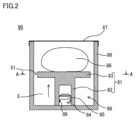
- FIG. 2 is a schematic cross-sectional view of the safety device 90 for an aircraft shown in FIG.
- the flight vehicle safety device 90 includes an actuator 88 as an injection device and a paraglider 86.
- the actuator 88 is integrally formed with a gas generator (drive unit) 84 having a cup-shaped case 85 for containing an igniter (not shown), a recess forming portion (concave member) 82 and the recess forming portion 82.
- a piston 81 (moving member) having a piston head 83 (launch pad), and a bottomed cylindrical housing 80 (container) that accommodates the piston 81 and regulates the direction of propulsion of the piston 81 are provided.
- the paraglider 86 is accommodated in the housing 80 in a non-deployed state and disposed on the piston head 83.
- One end of a connecting member (line or cord) is connected to the paraglider 86, and the other end of the connecting member is connected to any part of the actuator 88 or to the flying object 100.
- the paraglider 86 forms an airfoil shape by entraining air in a state of being injected into the air and deployed, and is formed of, for example, a reinforced cloth made of chemical fiber such as nylon or polyester. More specifically, as a base fabric of paraglider 86, for example, nylon 6, nylon 66, nylon 12, nylon 46, nylon 56, nylon 610, copolyamide of nylon 6 and nylon 66, and polyalkylene glycol to nylon 6 A copolymerized polyamide obtained by copolymerizing a dicarboxylic acid, an amine or the like, a polyester resin such as polyethylene terephthalate, polybutylene terephthalate or polytrimethylene terephthalate, a polyacrylic resin, or a polyolefin resin such as polypropylene can be used. Among them, polyamide 66 excellent in impact resistance and heat resistance can be suitably used particularly as a base fabric of the paraglider 86.
- a coating layer may be separately applied to the base fabric of Paraglider 86 in order to impart high heat resistance, and as the coating layer to be applied, for example, silicone resin, polyurethane resin, polyacrylic resin, polyamide resin
- silicone resin can be used as the coating layer to be applied.
- silicone resin can be used. It is particularly preferred to use.
- silicone resin not only heat resistance, but also cold resistance, flame retardancy and air barrier properties can be enhanced.
- dimethyl silicone resin, methyl vinyl silicone resin, methylphenyl silicone resin, fluoro silicone resin can be used.
- the coating layer preferably further contains a flame retardant compound.
- flame retardant compounds halogen compounds containing bromine, chlorine and the like (especially halogenated cycloalkanes), platinum compounds, antimony oxides, copper oxide, copper oxides, titanium oxides, phosphorus compounds, thiourea compounds, carbon, cerium, silicon oxides, etc.
- a halogen compound, a platinum compound, copper oxide, titanium oxide and carbon it is more preferable to use a halogen compound, a platinum compound, copper oxide, titanium oxide and carbon.
- the coating layer is preferably selected in accordance with the material of the yarn to be used as the base fabric, and is preferably made of a material that adheres tightly to the warp and weft.
- the coating layer is preferably a polyurethane resin or a polyacrylic resin.
- FIG. 3A is a schematic cross-sectional view taken along the line AA of the safety device 90 for an aircraft shown in FIG.
- a communication portion 51 which is a clearance, is formed between the inner wall of the housing 80 and the outer peripheral portion of the piston head 83.
- the piston 81 When the piston 81 is moved in the direction of the arrow shown in FIG. 2 by the operation of the gas generator 84, it is a space located on the opposite side to the opening of the housing 80 as viewed from the piston head 83 and A negative pressure is generated in the space S surrounded by the housing 80 and the piston 81. However, air flows from the space located outside the space S into the space S via the communicating portion 51 at this time. As a result, the magnitude of the negative pressure generated in the piston 81 is reduced, and the movement of the piston 81 can be performed smoothly.
- the gas generator 84 is inserted into a recess provided in the recess forming portion 82, and a gas outlet is provided at the tip of the gas generator 84. Thereby, the gas generator 84 can generate gas serving as a motive force for moving the piston 81 in the direction of the arrow shown in FIG.
- a seal member 89 such as an O-ring is provided between the recess provided in the recess forming portion 82 and the outer wall portion of the gas generator 84 so as to prevent gas leakage at the time of operation.
- the gas generator 84 internally has an igniter containing an igniter (propellant), and further has a propellant such as a transfer agent, a filter, etc. in addition to the gas generator or this as required. Explosive type.
- the gas generating agent it is preferable to use a non-azide gas generating agent, and in general, the gas generating agent is formed as a molded body containing a fuel, an oxidant and an additive.
- a fuel for example, a triazole derivative, a tetrazole derivative, a guanidine derivative, an azodicarbonamide derivative, a hydrazine derivative or the like or a combination thereof is used.
- nitroguanidine, guanidine nitrate, cyanoguanidine, 5-aminotetrazole and the like are suitably used.
- the oxidizing agent is selected from, for example, basic nitrates such as basic copper nitrate, perchlorates such as ammonium perchlorate and potassium perchlorate, or alkali metals, alkaline earth metals, transition metals and ammonia. Nitrates and the like containing the selected cations are used. As the nitrate, for example, sodium nitrate, potassium nitrate and the like are suitably used. Moreover, a binder, a slag formation agent, a combustion regulator etc. are mentioned as an additive.
- a metal salt of carboxymethyl cellulose for example, a metal salt of carboxymethyl cellulose, an organic binder such as stearate, or an inorganic binder such as synthetic hydrotalcite or acid clay can be suitably used.
- an organic binder such as stearate, or an inorganic binder such as synthetic hydrotalcite or acid clay
- a slag forming agent silicon nitride, silica, acid clay etc. can be suitably used.
- metal oxides, ferrosilicon, activated carbon, graphite and the like can be suitably used.
- a single base powder based on nitrocellulose, a double base powder, or a triple base powder may be used.
- the shape of the gas generating agent molded body there are various shapes such as granular shape such as granular shape, pellet shape and cylindrical shape, and disk shape.
- granular shape such as granular shape, pellet shape and cylindrical shape, and disk shape.
- cylindrical thing the thing (for example, single-hole cylinder shape or porous cylinder shape etc.) which has a through-hole in the inside of a molded object is also utilized.
- a hybrid-type or stored-type gas generator which cleaves a sealing plate in a small gas cylinder with a pyrotechnic igniter and discharges the internal gas to the outside.
- a pressurized gas in the gas cylinder noncombustible gas such as argon, helium, nitrogen, carbon dioxide or a mixture thereof can be used.
- a pyrotechnic-type heating element may be provided in the gas generator in order to reliably propel the piston 81 when the pressurized gas is released.
- the propulsion of the piston 81 allows the paraglider 86 to be pushed out and deployed directly.
- the open end of the housing 80 provided with the opening is closed by the lid 87 in the initial state, and the lid 87 is configured to be released from the open end by the extrusion of the paraglider 86.
- the piston 81 may be configured to be directly pushed out by the gas generated by the gas generator 84, or a drive unit such as a spring, compressed gas or motor for driving the piston 81 may be separately provided.
- the drive unit may be configured to be pushed out by being operated by the gas generated by the gas generator 84.
- the piston 81 may be connected to the housing 80 so as to have a telescopic structure with the bottomed cylindrical housing 80 which regulates the moving direction of the piston 81.
- the flight vehicle safety device 90 includes an anomaly detection device 40 (see FIG. 4) including an acceleration sensor or the like that detects an anomaly of the flight vehicle 100.
- an abnormality detection device 40 when an abnormality is detected by the abnormality detection device 40, the piston 81 is propelled by the gas pressure generated based on the ignition operation of the gas generator 84. Thereby, the paraglider 86 is directly pushed out by the propulsive force generated by the piston 81 propelling.
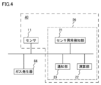
- FIG. 4 is a functional block diagram of the aircraft safety device 90 shown in FIG.
- the abnormality detection device 40 includes a sensor (detection unit) 11 and a control unit (a computer having a central processing unit (CPU), a read only memory (ROM), a random access memory (RAM)), and the like. And is electrically connected to the igniter in the gas generator 84 provided in the flight vehicle safety device 90.
- a sensor detection unit
- control unit a computer having a central processing unit (CPU), a read only memory (ROM), a random access memory (RAM)
- CPU central processing unit
- ROM read only memory
- RAM random access memory
- the sensor 11 detects the flight state (including collision, crash, and the like) of the flying object 100.
- the sensor 11 is configured by selecting one or more of, for example, an acceleration sensor, a gyro sensor, an air pressure sensor, a laser sensor, an ultrasonic sensor, etc. Data on the flying state of the flying object 100, such as tilt, altitude, and position, can be acquired.
- the control unit 20 includes a sensor malfunction detection unit 21, a calculation unit 22, and a notification unit 23 as a functional configuration.
- the sensor abnormality detection unit 21, the calculation unit 22 and the notification unit 23 are functionally realized by the control unit 20 executing a predetermined program.
- the sensor abnormality detection unit 21 detects an abnormal state of the sensor 11. That is, the sensor abnormality detection unit 21 detects whether the sensor 11 can operate normally.
- the calculation unit 22 determines whether or not the flight state of the flying object 100 is abnormal based on each data acquired by measurement by the sensor 11. Specifically, the computing unit 22 determines whether or not the aircraft 100 has received an impact (or determines whether or not the vehicle has collided), or determines the prediction of the crash of the aircraft 100. In addition, when it is determined that the flight state of the flying object 100 is abnormal, the computing unit 22 also outputs an abnormal signal (which may include a command signal for activating or activating another device) to the outside. . Note that an abnormal signal output unit may be provided separately from the arithmetic unit 22, and the abnormal signal output unit may output an abnormal signal according to an instruction from the arithmetic unit 22.
- the notification unit 23 notifies an administrator or the like that an abnormality of the sensor 11 is detected when the sensor abnormality detection unit 21 detects an abnormality of the sensor 11.
- an abnormality inspection of the sensor 11 by the sensor abnormality detection unit 21 is performed. Specifically, the sensor abnormality detection unit 21 checks whether an acceleration sensor or the like that measures the acceleration of the flying object 100 operates normally.
- the sensor abnormality detection unit 21 notifies an administrator or the like of an error, and ends the operation.
- the calculation unit 22 reads each data measured by the sensor 11.
- the calculation unit 22 outputs a signal to return to the processing of the abnormality inspection of the sensor 11 by the sensor abnormality detection unit 21.
- the computing unit 22 outputs a safety device activation signal (abnormal signal) to the gas generator 84 of the safety device 90 for a flight vehicle.
- the gas generator 84 is activated upon receiving the safety device activation signal, whereby the actuator 88 is driven. As a result, the paraglider 86 is developed by being ejected.
- the present embodiment it is possible to reduce the magnitude of the negative pressure generated at the time of driving, and at least a part of the propulsive force of the piston 81 is offset by the negative pressure. Can be suppressed.
- the piston head 83 and the inner wall of the housing 80 do not come in contact with each other, frictional resistance does not occur in the portion. Therefore, also in this point, it is possible to suppress the reduction of the propulsive force at the time of ejection of the paraglider 86 in advance.
- injection of the object to be deployed can be performed more reliably than in the conventional case, and injection and development of the object to be deployed can be performed easily and accurately.
- the communication portion 51 having the above-described configuration is capable of causing air to flow from the outer periphery of the piston head 83 into the space S in a well-balanced manner when the piston 81 is injected, It is possible.
- the gas generator 84 which ejects gas by receiving an electric signal and operating is used as a drive part, the timing of a drive can be controlled easily.
- the gas generator 84 is constituted by a pyrotechnic type, it becomes possible to instantly obtain a propulsive force for moving the piston 81.
- a flight vehicle safety apparatus equipped with a paraglider and a flight vehicle equipped with the same have been described as an example to be deployed, but a parachute may be provided instead of the paraglider.
- the safety device for a flight vehicle equipped with a parachute as a deployable vehicle and a flight vehicle equipped with the same can be obtained.
- FIGS. 3B to 3F are schematic cross-sectional views of a safety device for a flying object according to first to fifth modifications.
- a communicating part was constituted by the crevice was illustrated by providing crevice between the inner wall of a housing, and the peripheral part of a piston head, for example, FIG. 3 (B)-FIG. It may be a safety device for a flying object as shown in F).
- FIGS. 3B to 3F parts similar to those shown in FIG. 3A have the same reference numerals and suffixes as the reference numerals shown in FIG. 3A. Reference numerals are attached. Therefore, for example, the portion indicated by the reference numeral 80 and the portion indicated by the reference numeral 80b are the same portions.
- the safety device for a flying object according to the first modification shown in FIG. 3B has the same diameter as the inner diameter of the housing 80b and the outer diameter of the piston head 83b, and one of the outer peripheral portions of the piston head 83b.
- the aircraft safety device 90 according to the first embodiment is different from the safety device 90 according to the first embodiment in that a pair of communication parts 52 (notches) are provided in the outer peripheral part by cutting out parts.
- the communication portion 52 has the same function as the communication portion 51 in the first embodiment, and the magnitude of the negative pressure generated in the space S (see FIG. 1) when the piston 81 b moves is determined. To reduce.
- the communication portion 52 may be provided so as to be rotationally symmetrical with respect to the center of the piston head 83b, or one or three or more may be provided at an arbitrary position on the outer peripheral portion.
- the communication portion 52 is provided so as to be rotationally symmetrical with respect to the center of the piston head 83b, air is allowed to flow into the space S from the communication portions 52 evenly arranged at the time of movement of the piston 81b.
- the moving posture of the piston 81 b can be easily maintained.
- the frictional resistance between the piston head 83b and the inner wall of the housing 80b can be reduced in a well-balanced manner, it is possible to prevent the reduction of the propulsive force at the time of operation.
- the safety device for a flying object according to the second modification shown in FIG. 3C has the same diameter as the inner diameter of the housing 80c and the outer diameter of the piston head 83c, and the piston head 83c on the inner wall of the housing 80c.
- the configuration is different from that of the safety device for a flying object according to the first embodiment in that a pair of groove-shaped communicating parts 53 (groove parts) formed along the ejection direction is provided.
- the communication portion 53 has the same function as the communication portion 51 in the first embodiment, and the magnitude of the negative pressure generated in the space S (see FIG. 1) when the piston 81 c moves is determined. To reduce.
- the communication portion 53 may be provided so as to be rotationally symmetrical with respect to the center of the piston head 83c, or may be provided one or three or more at any position on the inner wall of the housing 80c.
- the communication portion 53 is provided so as to be rotationally symmetrical with respect to the center of the piston head 83c, air is made to flow into the space S in a well-balanced manner from the communication portion 53 evenly arranged when the piston 81c moves.
- the moving posture of the piston 81c can be easily maintained.
- the frictional resistance between the piston head 83c and the inner wall of the housing 80c can be reduced in a well-balanced manner, it is possible to prevent the reduction of the propulsive force during the operation.
- the safety device for a flying object according to the third modification shown in FIG. 3D has the same diameter as the inner diameter of the housing 80d and the outer diameter of the piston head 83d, and a through hole shape in the piston head 83d.
- the configuration is different from the safety device for a flying object according to the first embodiment in that a pair of communication portions 54 (a hole portion) is formed.
- the communication portion 54 is a pair of spaces separated by the piston head 83d (that is, a space located on the opening side of the housing 80d as viewed from the piston head 83d) and an opening side of the housing 80d as viewed from the piston head 83d. Are provided to face the space located on the opposite side (ie, the space S (see FIG. 1)).
- the communication portion 54 has the same function as the communication portion 51 in the first embodiment, and reduces the magnitude of the negative pressure generated in the space S when the piston 81 d moves. .
- the communication portion 54 may be provided so as to be rotationally symmetrical with respect to the center of the piston head 83 d, or at any position of the piston head 83 d other than the position communicating with the recess provided in the recess forming portion 82 d. One or three or more may be provided. In the case where the communication portion 54 is provided so as to be rotationally symmetrical with respect to the center of the piston head 83 d, air is allowed to flow into the space S from the communication portions 54 evenly arranged when the piston 81 d moves. As a result, the movement posture of the piston 81d can be easily maintained.
- the safety device for a flying object according to the fourth modification shown in FIG. 3E is that the inner diameter of the housing 80e and the outer diameter of the piston head 83e have the same diameter, and the piston head 83e has a through hole shape.
- the configuration is different from that of the safety device for a flight vehicle according to the first embodiment in that three communication portions 55 (hole portions) are formed.
- the three communication parts 55 are formed at positions rotated by 120 ° with respect to the center of the piston head 83e, and the safety device for a flying object according to the present modification is only for this point.
- the configuration is different from the safety device for a flying object according to the third modification.
- the safety device for a flying object according to the fifth modification shown in FIG. 3F is that the inner diameter of the housing 80f and the outer diameter of the piston head 83f are the same diameter, and the piston head 83f has a through hole shape.
- the aircraft safety device according to the first embodiment is different in configuration from the flight vehicle safety device according to the first embodiment in that it is configured by a reticulated member in which a plurality of communication portions 56 (holes) are formed.
- the communication portion 56 is a pair of spaces separated by the piston head 83f (that is, a space located on the opening side of the housing 80f as viewed from the piston head 83f) and an opening side of the housing 80f as viewed from the piston head 83f. Is provided to face the space located on the opposite side (that is, the space S (see FIG. 1).
- the mesh-like member includes not only the mesh-like member but also a grid-like member.
- the communication portion 56 has the same function as the communication portion 51 in the first embodiment, and reduces the magnitude of the negative pressure generated in the space S when the piston 81 f moves. .
- the plurality of communication portions 56 are uniformly provided on the piston head 83 f, so air can be well balanced from the plurality of communication portions 56 when the piston 81 f moves. Can flow into the space S, and the moving posture of the piston 81 f can be easily maintained.
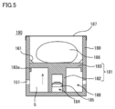
- FIG. 5 is a schematic cross-sectional view of an aircraft safety device 190 according to a sixth modification.
- the gap or the hole is provided by providing a gap between the inner wall of the housing and the outer periphery of the piston head or by providing a hole in the piston head.
- the communicating portion is configured
- the flight vehicle safety device 190 having a configuration as shown in FIG. 5 may be used, for example.
- the configuration given the same lower two-digit code as the lower two-digit code attached to the configuration shown in FIG. 2 is basically the same as the configuration described in FIG. Because there is a case, the description may be omitted.
- the safety device for aircraft body 190 according to the sixth modification shown in FIG. 5 has a point that a pair of communication parts 151 are formed on the side of the housing 180, and a pair of projections 161 (stopper parts) on the inner wall of the housing 180.
- the configuration is different from that of the aircraft safety device 90 according to the first embodiment in that a ring-shaped guide portion 183a is formed on the outer peripheral portion of the piston head 183.
- the communication portion 151 has the same function as the communication portion 51 in the first embodiment, and reduces the magnitude of the negative pressure generated in the space S when the piston 181 moves. .
- the communication portion 151 may be provided so as to be rotationally symmetrical with respect to the center of the housing 180, or may be provided at one or more than one of the side portions of the housing 180.
- the communication portion 52 is provided so as to be rotationally symmetrical with respect to the center of the housing 180, air may be made to flow into the space S from the communication portions 151 evenly arranged at the time of movement of the piston 181. As a result, the movement posture of the piston 181 can be easily maintained.
- the projecting portion 161 prevents movement of the piston head 183 (piston 181) before the operation by abutting on the piston head 183 before the operation, and from the inner wall surface of the housing 180 to the inside of the housing 180. It is projected towards the space.
- the piston 181 moves by the piston head 183 moving over the projection 161 due to the strong propulsive force generated by the gas generator 184 operating.
- the protrusions 161 may be provided so as to be rotationally symmetrical with respect to the center of the housing 180, or may be provided at one or more than one at any position on the side of the housing 180.
- the protrusion 161 may be formed in a ring shape on the entire inner peripheral portion of the housing 180.
- the guide portion 183a guides the movement of the piston 181 along the inner wall of the housing 180, and is a ring-shaped and projecting member protruding from the outer peripheral portion of the piston head 183 along the inner wall of the housing 180. It consists of parts. Preferably, the thickness of the guide portion 183 a in the direction along the inner wall of the housing 180 is larger than the thickness of the piston head 183 in the corresponding direction. By providing the guide portion 183a, the sliding contact surface between the housing 180 and the piston 181 becomes large, so that the moving posture of the piston 181 can be easily maintained.
- the protrusion 161 may be provided independently at one position on the outer peripheral portion of the piston head 183 so as to be rotationally symmetrical with respect to the center of the piston head 183, or may be provided at a plurality of positions spaced apart. Good.
- the piston head 183 (piston 181) before operation is provided by providing the protrusion 161. Can be prevented, and even if it is attached to a flying object, an effect is obtained that can be prevented from interfering with the autonomous control of the flying object.
- the piston head 183 (piston 181) can be easily moved along the inner wall of the housing 180 by providing the guide portion 183a. You can also get the effect of being able to smooth the movement of the
- FIG. 6 is a schematic cross-sectional view of an aircraft safety device 290 according to a seventh modification.
- the safety device 290 for flight vehicles may be configured as shown in FIG.
- the configuration given the same lower two digits as the lower two digits given to the configuration shown in FIG. 2 is basically the same as the configuration described in FIG. Because there is a case, the description may be omitted.
- the flight vehicle safety device 290 according to the seventh modification shown in FIG. 6 is restricted in that a cord-like member 261 connecting the inner wall of the housing 280 and the piston head 283 is provided, and around the gas generator 284.
- the configuration is different from that of the aircraft safety device 90 according to the first embodiment in that the member 291 is provided.
- the string-like member 261 is provided to connect the piston head 283 before operation and the inner wall of the housing 280, thereby preventing the movement of the piston head 283 (piston 281) before operation.
- the piston 281 is moved by the strong propulsive force generated by the operation of the gas generator 284 so that tension is generated in the string-like member 261, whereby the string-like member 261 is cut.
- a cutting device (not shown) may be separately provided, and the string-like member 261 may be cut by the cutting device simultaneously with the operation of the gas generator 284.
- the cutting device may drive the motor for moving the cutter or the like to receive the electric signal to cut the string-like member 261, or may generate heat to burn it off.
- a mechanism configured to separate one end of the string-like member 261 held in advance at the time of operation may be used.
- the restricting member 291 is disposed so as to surround the gas generator 284 so as to restrict the ejection direction of the gas ejected from the gas generator 284. More specifically, the restricting member 291 moves the piston 281 in the direction of movement of the piston 281 toward the opening of the housing 280 as shown in FIG. In the direction of the arrow), the piston 281 is sprayed.
- the restricting member 291 is preferably formed of a cylindrical member so that the gas generator 284 can be inserted.
- the piston 281 can be extrapolated to the restricting member 291 as follows: It is preferable that the recess forming portion 282 of the piston 281 also have a cylindrical shape.
- the provision of the string-like member 261 provides a piston head 283 (piston 281 before operation). Can be prevented, and even if attached to a flying object, it can be prevented from interfering with the autonomous control of the flying object.
- the provision of the restriction member 291 enables the gas ejection direction to be concentrated in a predetermined direction, so that the propulsive force can be obtained more efficiently. Further, since the piston head 283 (piston 281) moves along the outer wall of the restriction member 291 by providing the restriction member 291, smooth movement of the piston head 283 (piston 281) when moving Can.
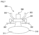
- FIG. 7 is a schematic front view showing a state after the air bag 311 is deployed, of the flying body 300 provided with the safety device for flight body 390 according to the second embodiment.
- the configuration to which the same lower one-digit code as that of the configuration shown in FIG. 1 is attached is basically the same as the configuration described in FIG. The description may be omitted.
- the safety device for flight vehicle 390 according to the present embodiment is different from the safety device for flight vehicle 90 according to the first embodiment, and the main body of the safety device for flight vehicle 390 is normally An air bag apparatus 310 provided under the fuselage 301 of the flying object 300 at the time of the attitude and being a part of the safety device for aircraft 390 is provided for the flying object provided at the lower part of the body 301 at the normal attitude.
- the main body portion of the safety device 390 is further provided on the upper portion of the airframe 301 at the normal posture so as to face the airframe 301 with the airframe 301 interposed therebetween.
- the air bag device 310 includes an air bag 311 and a gas generator, and inflates the air bag 311 by gas pressure generated based on the ignition operation of the gas generator.
- the gas generator may be any type as long as it can supply the gas into the air bag, and may be a pyrotechnic type equipped with an igniter, or may be a cylinder type instead. Or the like.
- the main body of the aircraft safety device 390 is the same as the aircraft safety device 90 according to the above-described embodiment, and is configured to be able to eject a paraglider.
- a safety device activation signal is output to the gas generator of the air bag device 310 from the abnormality detection device having the same configuration as that of the above-described abnormality detection device 40, whereby the gas generator is operated.
- the air bag 311 When the gas generator operates, the air bag 311 is injected and expanded by the gas pressure generated by the gas generator. Thereby, when the flying object 300 falls, obstacles and loads, particularly pedestrians can be protected.
- the abnormality is The safety device start signal is not output from the detection device to the gas generator.
- the air bag device 310 when the air bag device 310 is provided with the abnormality detection device, it is possible to more reliably prevent the air bag device 310 from malfunctioning. Therefore, the reliability of the safety of the air bag device 310 can be improved.
- the other effects and advantages are the same as in the case of the above-described aircraft safety device 90.
- a safety device for a flight vehicle equipped with a paraglider and an air bag as a deployable vehicle and a flight vehicle equipped with the same will be described.
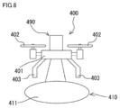
- FIG. 8 is a schematic front view showing a state after the air bag 411 is deployed, of the aircraft 400 provided with the safety device 490 for aircraft according to the third embodiment. It is to be noted that, in FIG. 8, the configuration to which the same lower one-digit code as that of the configuration shown in FIG. 1 is attached is basically the same as the configuration described in FIG. The description may be omitted.
- the flight vehicle safety device 490 is an air that is a part of the flight vehicle safety device 490.
- the lower part of the airframe 401 in the normal posture is such that the bag device 410 is opposed to the main body of the safety device for airframe 490 provided on the upper part of the airframe 401 of the aircraft 400 in the normal posture with the airframe 401 interposed.
- the air bag device 410 includes an air bag 411 and a gas generator, and inflates the air bag 411 by the gas pressure generated based on the ignition operation of the gas generator.
- the gas generator may be any type as long as it can supply the gas into the air bag, and may be a pyrotechnic type equipped with an igniter, or may be a cylinder type instead. Or the like.
- the main body of the aircraft safety device 490 is the same as the aircraft safety device 90 according to the above-described embodiment, and is configured to be able to eject a paraglider.
- a safety device activation signal is output to the gas generator of the air bag device 410 from the abnormality detection device having the same configuration as the above-described abnormality detection device 40, whereby the gas generator is operated.
- the air bag 411 When the gas generator operates, the air bag 411 is injected and expanded by the gas pressure generated by the gas generator. Thereby, when the flying object 400 falls, obstacles and loads, particularly pedestrians can be protected. Further, in the present embodiment, various devices often provided at the lower part of the airframe 401 can be protected by the air bag 411.
- the abnormality is The safety device start signal is not output from the detection device to the gas generator.
- the air bag device 410 when the air bag device 410 is provided with the abnormality detection device, it is possible to more reliably prevent the air bag device 410 from malfunctioning. Therefore, the reliability of the safety of the air bag device 410 can be improved.
- the other effects and advantages are the same as in the case of the above-described aircraft safety device 90.
- the present invention is not limited to this. This may be realized by hardware.
- cross-sectional shape of the communication portion in the above-described embodiment and the modified examples thereof is not particularly limited, and may be any shape.
- a non-prone type gas generator such as a cylinder type may be used.
- a micro gas generator MMG having a structure such that a gas jet port is formed by an increase in internal pressure due to gas generated at the time of operation Or squibs may be used instead of the gas generator described above.
- the present invention is an apparatus for deploying a parachute, paraglider or airbag mounted on a flying object, comprising: a container having an opening at one end, the deployable parachute, the paraglider or the airbag A movable member provided in the container and having a launch pad on the opening side on which the parachute, the paraglider or the airbag is mounted, and a movable member movable along the inner wall of the container, and the movable member A drive unit capable of injecting the light toward the opening, and a connecting member having one end connected to the parachute, the paraglider or the airbag, and the other end connected to a flying object or a device attached to the flying object A communicating portion for communicating the inside of the space surrounded by the container and the moving member with the outside of the space, the container, the launch pad And characterized in that provided in at least one of between the inner wall of the container and the launching pad.
- the negative pressure at the time of driving can be reduced, and it is possible to suppress that at least a part of the propulsive force is offset by the negative pressure. That is, it is possible to suppress a decrease in propulsive force at the time of injection of the parachute, paraglider or airbag. Therefore, the injection and deployment of the parachute, paraglider or airbag can be made easier and more accurate than in the prior art.
- the communication portion is provided with a hole portion provided in the container, a hole portion provided in the launch pad, and between the inner wall of the container and the launch pad
- a gap provided between the inner wall of the container and the launch pad means, for example, in addition to a simple gap, provided on the inner wall of the container along the injection direction of parachute, paraglider or airbag.
- the grooves include those due to the grooves, or those due to the notches cut out in the radial direction on the outer peripheral portion of the launch pad.
- the container or / and the launch pad be provided with a stopper portion for preventing movement of the launch pad before actuation of the drive unit.
- the stopper portion is a projection portion provided to protrude on the inner wall of the container.
- the stopper portion is a string-like member that connects the inner wall of the container and the launch pad, and the string-like member is driven by the driving portion When done, it is preferable to be cut by a tension or cutting device.
- the movement of the launch pad before operation can be prevented, so that even if it is attached to the flying object, it can be prevented from interfering with the autonomous control of the flying object.
- a guide member longer than the thickness of the launch pad is protruded along the inner wall of the container from the outer peripheral portion of the launch pad.
- the guide member may be annular, or may be a member formed of a part with at least one protrusion or the like, or a member formed of a plurality of members at intervals.
- the launch pad (moving member) can be easily moved along the inner wall of the container, the movement of the launch pad (moving member) can be made smooth.
- the drive unit is a gas generator that operates with an electrical signal to generate a gas.
- the drive timing of the drive unit can be easily controlled.
- the gas generator is a pyrotechnic gas generator having a propellant that generates a combustion gas serving as a motive force for moving the moving member.
- the gas generator has a gas outlet on the side of the opening or the gas outlet due to an increase in internal pressure due to the gas generated at the time of operation. It is preferable that a restriction member is provided around the gas generator to restrict the flow path of the gas jetted from the gas jet port in the direction of the opening.
- the moving member further includes a concave member whose bottom is connected to the launch pad, and the gas generator sprays a gas to the opening side. It has an outlet, is inserted in the concave member so that at least the gas jet is located inside the concave member, and a sealing member is provided between the concave member and the gas generator. Is preferred.
- An airframe according to the present invention is connected to an airframe, a parachute, a paraglider or an air bag deployment device according to any one of (1) to (10) connected to the airframe, and the airframe. And one or more propulsion mechanisms for propelling an airframe.
- Reference Signs List 1 aircraft, 2 propulsion mechanism, 3 legs, 11 sensors, 20 control units, 21 sensor abnormality detection units, 22 calculation units, 23 notification units, 40 abnormality detection devices, 51 to 56 communication units, 80, 80b to 80f housings, 81, 81b to 81f piston, 82, 82b to 82f recessed portion, 83, 83b to 83f piston head, 84 gas generator, 85 case, 86 paraglider, 87 lid, 88 actuator, 89 seal member, 90 safety for flying object Device, 100 flying body, 151 communicating portion, 161 projecting portion, 180 housing, 181 piston, 182 recessed portion forming portion, 183 piston head, 183a guiding portion, 184 gas generator, 185 case, 186 paraglider, 187 lid, 188 actuator 190 Flight Vehicle Safety Device, 251 Communication Unit, 261 String Member, 280 Housing, 281 Piston, 282 Recess Forming Unit, 283 Piston Head, 284 Gas Generator, 285 Case, 286 Paraglider, 2
Abstract
飛行体用安全装置(90)は、被展開体(86)および射出装置(88)を備える。射出装置(88)は、被展開体(86)を収容するとともに、開口部が一端部側に設けられた容器(80)と、容器(80)内に設けれ、被展開体(86)が載置される発射台(83)を上記開口部側に有するとともに、容器(80)の内壁に沿って移動可能な移動部材(81)と、移動部材(81)を上記開口部側に向けて移動させることで被展開体(86)を射出する駆動部(84)とを有する。発射台(83)から見て上記開口部側とは反対側に位置する空間であってかつ容器(80)および移動部材(81)によって囲まれてなる空間(S)は、当該空間(S)の外側に位置する空間と連通部(51)を介して連通する。
Description
本発明は、例えばドローン等に代表されるような飛行体および当該飛行体に取付けられる飛行体用安全装置に関する。
従来、各種の飛行体が知られている。飛行体には、旅客機やヘリコプターのような有人航空機に限られず、無人航空機も含まれる。特に近年、自律制御技術および飛行制御技術の発展に伴って、例えばドローンのような無人航空機の産業上における利用が加速しつつある。
ドローンは、例えば複数の回転翼を備えており、これら複数の回転翼を同時にバランスよく回転させることによって飛行する。その際、上昇および下降は、複数の回転翼の回転数を一律に増減させることによって行なわれ、前進および後退は、複数の回転翼の各々の回転数を個別に増減させることで機体を傾けることによって行なわれる。このような無人航空機の利用は、今後世界的に拡大することが見込まれている。
しかしながら、無人航空機の落下事故のリスクが危険視されており、無人航空機の普及の妨げとなっている。こうした落下事故のリスクを低減するために、安全装置としての無人航空機用パラシュート装置が製品化されつつある。このような無人航空機用パラシュート装置は、無人航空機の落下時において、展開させたパラシュートによって無人航空機の速度を減速させることで着地時の衝撃を低減するものである。
たとえば、欧州特許出願公開第3050805号明細書には、飛行体用安全装置として、ガス発生器に含まれる火薬の推進力を利用して筒内でピストン部を動作させ、このピストン部の動作によってパラシュートを開口部から外部へ射出して開傘させるものが開示されている。
しかしながら、上記特許文献1に開示の飛行体用安全装置においては、ガス発生器に含まれる火薬が発火することによって筒内においてピストン部が移動することに伴い、筒内のピストン部の内側の空間において負圧が発生してしまい、これによりピストンを移動させる推進力の少なくとも一部が相殺されてしまう問題がある。なお、この負圧の発生によって十分な推進力を得ることができなかった場合には、パラシュートの外部への射出が不十分となり、パラシュートの展開が困難になるおそれがある。
この問題は、パラシュートに代えて、飛行体に射出可能にパラグライダー、エアバッグ等を設けた場合においても、同様に発生する問題である。
そこで、本発明は、上述した問題を解決すべくなされたものであり、被展開体の射出が確実に行なえる飛行体用安全装置およびこれを備えた飛行体を提供することを目的とする。
本発明に基づく飛行体用安全装置は、飛行体に取付けが可能なものであって、被展開体と、射出装置と、連結部材とを備えている。上記被展開体は、空中に射出されることで展開が可能になるものであり、上記射出装置は、上記被展開体を空中に向けて射出するためのものである。上記連結部材は、一端が上記被展開体に連結されているとともに、他端が上記射出装置に連結されているかあるいは飛行体に連結されるものである。上記射出装置は、上記被展開体を収容するとともに、開口部が一端部側に設けられた容器と、上記容器内に設けれ、上記被展開体が載置される発射台を上記開口部側に有するとともに、上記容器の内壁に沿って移動可能な移動部材と、上記移動部材を上記開口部側に向けて移動させることで上記被展開体を射出する駆動部とを有している。上記本発明に基づく飛行体用安全装置にあっては、上記発射台から見て上記開口部側とは反対側に位置する空間であってかつ上記容器および上記移動部材によって囲まれてなる空間と、当該空間の外側に位置する空間とを連通させる連通部が、上記射出装置に設けられている。
上記本発明に基づく飛行体用安全装置にあっては、上記連通部が、上記容器および上記発射台の少なくともいずれかに設けられた孔部によって構成されているか、あるいは、上記容器と上記発射台との間に設けられた隙間によって構成されていることが好ましい。
上記本発明に基づく飛行体用安全装置にあっては、上記射出装置が、上記駆動部が作動する前の状態において上記発射台が移動することを防止するストッパー部をさらに有していてもよい。
上記本発明に基づく飛行体用安全装置にあっては、上記ストッパー部が、上記容器の内壁に設けられた突起部にて構成されていてもよい。
上記本発明に基づく飛行体用安全装置にあっては、上記ストッパー部が、上記容器の内壁と上記発射台とを繋ぐ紐状部材にて構成されていてもよく、その場合には、上記紐状部材が、上記駆動部による上記移動部材の駆動に伴って切断されるように構成されていることが好ましい。
上記本発明に基づく飛行体用安全装置にあっては、上記射出装置が、上記移動部材の上記容器の内壁に沿った移動を案内するためのガイド部をさらに有していてもよく、その場合には、上記ガイド部が、上記発射台の外周部から上記容器の内壁に沿って突設された突起状の部位にて構成されていることが好ましい。
上記本発明に基づく飛行体用安全装置にあっては、上記駆動部が、電気信号が入力されて作動することによってガスを噴出するガス発生器にて構成されていることが好ましい。
上記本発明に基づく飛行体用安全装置にあっては、上記ガス発生器が、上記移動部材を移動させる推進力となる燃焼ガスを発生する推進薬を具備した火薬式のものにて構成されていてもよい。
上記本発明に基づく飛行体用安全装置にあっては、上記射出装置が、上記ガス発生器を取り囲むように位置することで上記ガス発生器から噴出されるガスの噴出方向を規制する規制部材をさらに有していてもよい。その場合には、上記規制部材が、ガスの噴出方向を上記移動部材の上記開口部側に向けての移動方向に合致させて上記移動部材に噴き付けるようにするものであることが好ましい。
上記本発明に基づく飛行体用安全装置にあっては、上記移動部材が、上記開口部側とは反対側に向けて開口する凹部を規定する凹部形成部を含んでいるとともに、上記ガス発生器が、上記凹部内に配置されるように上記凹部形成部に挿入されていることが好ましい。その場合には、上記凹部形成部と上記ガス発生器との間に、シール部材が設けられていることが好ましい。
上記本発明に基づく飛行体用安全装置にあっては、上記被展開体が、パラシュート、パラグライダーおよびエアバッグのうちのいずれかにて構成されていることが好ましい。
このうち、パラシュートは、基布形状が傘の形をしているものが多く、保護対象物である飛行体と上記連結部材(一般に、コードあるいはラインと称される)を介してつながっており、空気抵抗を利用して飛行体を減速させるものである。また、パラシュートには、傘が一つのもの、同形状の傘が複数連結したもの、異形状の傘が複数連結したものがある。さらに、パラシュートには、傘の中心が閉じている(すなわち、穴が開いていない)もの、傘の中心にスピルホールと呼ばれる穴が開いているものがある。これらパラシュートの具体的な形態は、パラシュートの展開時におけるショックの低減や、沈下速度の調整、風等の外乱の影響を受けにくくするため等の種々の目的を考慮して、適宜選択することができる。
また、パラグライダーは、概ねアスペクト比が1以上の翼形状を有しており、保護対象物である飛行体と上記連結部材(一般に、コードあるいはラインと称される)を介してつながっている。さらに、パラグライダーには、ブレークコードと呼ばれる舵取り用のコードが、翼の左右端に繋がっている。このブレークコードを引っ張ることにより、翼断面に加わる種々の応力を変化させることができ、結果として滑空、旋回および急激な減速を行なうことができる。このため、パラグライダーは、パラシュートではできない、滑空、旋回および急激な減速を行なうことができる。同様の構成を有するものとして、ロガロタイプ、トライアングルタイプのパラグライダーも存在する。また、ラムエアを利用して翼形状を保つために、パラグライダーは、エアインテーク(後述する空気取り込み口)の有るものが主流ではあるが、このエアインテークが無いものも存在する。安定した飛行を行なうためには、エアインテーク付きのパラグライダーを用いることがより好ましい。なお、軽量化を図る観点からは、シングルサーフェスタイプのパラグライダー(すなわち、エアインテークが無いもの)を用いることが好ましい。さらに、プロペラ等の推進装置を別途設けることにより、強制的に推進力を得て飛行できるタイプのパラグライダーを用いてもよい。
本発明に基づく飛行体は、機体と、上記機体に設けられるとともに上記機体を推進させる推進機構と、上述した本発明に基づく飛行体用安全装置とを備えており、上記飛行体用安全装置が、上記機体に取付けられてなるものである。
本発明によれば、被展開体の射出が確実に行なえる飛行体用安全装置およびこれを備えた飛行体とすることができる。
以下、本発明の実施の形態について、図を参照して詳細に説明する。以下に示す実施の形態ならびにその変形例は、飛行体としての無人航空機であるドローンに本発明を適用した場合を例示するものである。
(実施の形態1)
まず、実施の形態1として、被展開体としてパラグライダーを具備した飛行体用安全装置およびこれを備えた飛行体について説明する。
まず、実施の形態1として、被展開体としてパラグライダーを具備した飛行体用安全装置およびこれを備えた飛行体について説明する。
図1は、実施の形態1に係る飛行体用安全装置90を備えた飛行体100の模式正面図である。図1に示すように、飛行体100は、機体1と、機体1に設けられるとともに当該機体1を推進させる1つ以上の推進機構(例えばプロペラ等)2と、機体1の下部に設けられた複数の脚部3と、機体1に取付けられた飛行体用安全装置90とを備えている。飛行体用安全装置90は、機体1上に設けられている。
図2は、図1に示す飛行体用安全装置90の模式断面図である。図2に示すように、飛行体用安全装置90は、射出装置としてのアクチュエータ88と、パラグライダー86とを備えている。アクチュエータ88は、点火薬(図示略)を収容するカップ状のケース85を有するガス発生器(駆動部)84と、凹部形成部(凹状部材)82および当該凹部形成部82と一体的に形成されたピストンヘッド83(発射台)を有するピストン81(移動部材)と、ピストン81を収容し当該ピストン81の推進方向を規制する有底筒状のハウジング80(容器)とを備えている。
パラグライダー86は、非展開状態とされるとともにピストンヘッド83上に配置された状態でハウジング80内に収容されている。パラグライダー86には、連結部材(ラインまたはコード)の一端が連結されており、連結部材の他端は、アクチュエータ88のいずれかの部位に連結されているかあるいは飛行体100に連結されている。
パラグライダー86は、空中に射出されて展開した状態において、空気をはらむことで翼型形状を成すものであり、たとえばナイロンあるいはポリエステル等の化学繊維製の強化クロスにて構成される。より具体的には、パラグライダー86の基布としては、例えばナイロン6、ナイロン66、ナイロン12、ナイロン46、ナイロン56、ナイロン610や、ナイロン6とナイロン66の共重合ポリアミド、ナイロン6にポリアルキレングリコール、ジカルボン酸、アミン等を共重合させた共重合ポリアミド、ポリエチレンテレフタレート、ポリブチレンテレフタレート、ポリトリメチレンテレフタレート等のポリエステル系樹脂、ポリアクリル系樹脂、ポリプロピレン等のポリオレフィン系樹脂を用いることができる。このうち、耐衝撃性および耐熱性に優れたポリアミド66が、特にパラグライダー86の基布として好適に使用できる。
また、高い耐熱性を付与するためにパラグライダー86の基布に別途コーティング層を施してもよく、施されるコーティング層としては、例えばシリコーン系樹脂、ポリウレタン系樹脂、ポリアクリル系樹脂、ポリアミド系樹脂、ポリエステル系樹脂、ポリオレフィン系樹脂、フッ素系樹脂等の各種の樹脂や、シリコーン系ゴム、クロロプレン系ゴム、クロロスルフォン化ポリエチレン系ゴム等の各種のゴムなどを用いることができるが、シリコーン系樹脂を用いることが特に好ましい。シリコーン系樹脂を用いることにより、耐熱性のみならず、耐寒性、難燃性、空気遮断性を高めることができる。かかるシリコーン系樹脂としては、ジメチル系シリコーン樹脂、メチルビニル系シリコーン樹脂、メチルフェニル系シリコーン樹脂、フロロ系シリコーン樹脂が利用できる。また、当該コーティング層は、さらに難燃化合物を含有していることが好ましい。かかる難燃化合物としては、臭素、塩素などを含むハロゲン化合物(特にハロゲン化シクロアルカン)、白金化合物、酸化アンチモン、酸化銅、酸化チタン、燐化合物、チオ尿素系化合物、カーボン、セリウム、酸化ケイ素などを用いることができ、これらの中でも特にハロゲン化合物、白金化合物、酸化銅、酸化チタン、カーボンを用いることがより好ましい。当該コーティング層は、基布となる織糸の材質に応じて適切なものを選択することが好ましく、経糸、緯糸に強固に密着する材質のものとすることが好ましい。例えば織糸がポリアミド糸またはポリエステル糸である場合には、コーティング層はポリウレタン系樹脂またはポリアクリル系樹脂等であることが好ましい。
図3(A)は、図2に示す飛行体用安全装置90のA-A線に沿った模式断面図である。図2および図3(A)に示すように、ハウジング80の内壁とピストンヘッド83の外周部との間には、隙間(クリアランス)である連通部51が形成されている。ガス発生器84が作動することによってピストン81が図2中に示す矢印方向に移動する際には、ピストンヘッド83から見てハウジング80の開口部側とは反対側に位置する空間であってかつハウジング80およびピストン81によって囲まれた空間Sに負圧が発生することになるが、空間Sに連通部51を介して当該空間Sの外側に位置する空間から空気が流入することにより、このときに発生する負圧の大きさが低減されることになり、ピストン81の移動がスムーズに行なえることになる。
ガス発生器84は、凹部形成部82に設けられた凹部内に挿入されており、ガス発生器84の先端部には、ガス噴出口が設けられている。これにより、ガス発生器84は、電気信号による点火によって、当該凹部内においてピストン81を図2中に示す矢印方向に向けて移動させる推進力となるガスを発生することができる。また、凹部形成部82に設けられた凹部とガス発生器84の外壁部との間には、作動時においてガス漏れが発生しないようにOリングなどのシール部材89が設けられている。
ガス発生器84は、点火薬(推進薬)を含む点火器を内部に有しており、必要に応じてガス発生剤またはこれに加えて伝火剤等の推進薬やフィルターなどをさらに有した火薬式のものである。
ガス発生剤としては、非アジド系ガス発生剤を用いることが好ましく、一般に燃料と酸化剤と添加剤とを含む成形体としてガス発生剤が形成される。燃料としては、たとえばトリアゾール誘導体、テトラゾール誘導体、グアニジン誘導体、アゾジカルボンアミド誘導体、ヒドラジン誘導体等又はこれらの組み合わせが利用される。具体的には、たとえばニトログアニジン、硝酸グアニジン、シアノグアニジン、5-アミノテトラゾール等が好適に利用される。また、酸化剤としては、たとえば塩基性硝酸銅等の塩基性硝酸塩、過塩素酸アンモニウム、過塩素酸カリウム等の過塩素酸塩、又は、アルカリ金属、アルカリ土類金属、遷移金属、アンモニアから選ばれたカチオンを含む硝酸塩等が利用される。硝酸塩としては、たとえば硝酸ナトリウム、硝酸カリウム等が好適に利用される。また、添加剤としては、バインダ、スラグ形成剤、燃焼調整剤等が挙げられる。バインダとしては、たとえばカルボキシメチルセルロースの金属塩、ステアリン酸塩等の有機バインダ、又は、合成ヒドロタルサイト、酸性白土等の無機バインダが好適に利用可能である。スラグ形成剤としては窒化珪素、シリカ、酸性白土等が好適に利用可能である。また、燃焼調整剤としては、金属酸化物、フェロシリコン、活性炭、グラファイト等が好適に利用可能である。また、ニトロセルロースを主成分としたシングルベース火薬、ダブルベース火薬、トリプルベース火薬を用いてもよい。
また、ガス発生剤の成形体の形状には、顆粒状、ペレット状、円柱状等の粒状のもの、ディスク状のものなど様々な形状のものがある。また、円柱状のものとしては、成形体内部に貫通孔を有する有孔状(たとえば単孔筒形状又は多孔筒形状等)のものも利用される。また、ガス発生剤の形状の他にもガス発生剤の線燃焼速度、圧力指数などを考慮に入れて成形体のサイズおよび充填量を適宜選択することが好ましい。
ここで、ガス発生器84の他の変形例として、火薬式の点火器で小型のガスボンベにおける封板を開裂させ、内部のガスを外部へと排出するハイブリッド型、ストアード型のガス発生器を用いてもよい。この場合、ガスボンベ内の加圧ガスとしては、アルゴン、ヘリウム、窒素、二酸化炭素などの不燃性のガスあるいはこれらの混合物を用いることができる。また、加圧ガスが放出される際に確実にピストン81を推進させるために、火薬式の発熱体をガス発生器に具備させてもよい。
このような構成において、ピストン81が推進することにより、パラグライダー86を直接押し出して展開させることができる。なお、ハウジング80の開口部が設けられた開口端部は、初期状態において蓋87によって閉じられており、当該蓋87は、パラグライダー86の押し出しによって上記開口端部から外れるように構成されている。
ピストン81は、ガス発生器84にて発生したガスによって直接押し出されるように構成してもよいし、ピストン81を駆動するためのバネや圧縮ガス、モーター等の駆動ユニットを別途設けておき、当該駆動ユニットがガス発生器84にて発生したガスによって作動させられることで押し出されるように構成してもよい。また、ピストン81は、ピストン81の移動方向を規制する有底筒状のハウジング80との間でテレスコピック構造を有するように当該ハウジング80と連結されていてもよい。
飛行体用安全装置90は、飛行体100の異常を検出する加速度センサ等を含む異常検出装置40(図4参照)を備えている。このような構成において、異常検出装置40によって異常が検出された場合に、ガス発生器84の点火動作に基づいて発生したガス圧によってピストン81が推進させられる。これにより、ピストン81が推進することで生じる推進力によってパラグライダー86が直接押し出されることになる。
図4は、図1に示す飛行体用安全装置90の機能ブロック図である。ここで、異常検出装置40の機能的構成について説明する。図4に示すように、異常検出装置40は、センサ(検知部)11と、制御部(CPU(Central Processing Unit)、ROM(Read Only Memory)、RAM(Random Access Memory)等を有するコンピュータ)20と、を備えており、飛行体用安全装置90に設けられたガス発生器84内の点火器と電気的に接続されている。
センサ11は、飛行体100の飛行状態(衝突、墜落などを含む)を検知するものである。具体的には、センサ11は、たとえば加速度センサ、ジャイロセンサ、気圧センサ、レーザーセンサ、超音波センサなどから1つ以上が選択されて構成されてなるものであり、飛行体100の速度、加速度、傾き、高度、位置など、飛行体100の飛行状態のデータを取得することができる。
制御部20は、機能的構成として、センサ異常検知部21と、演算部22と、通知部23とを備えている。これらのセンサ異常検知部21、演算部22および通知部23は、制御部20が所定のプログラムを実行することで機能的に実現されるものである。
センサ異常検知部21は、センサ11の異常状態を検知するものである。すなわち、センサ異常検知部21は、センサ11が正常に動作可能であるか否かを検知する。
演算部22は、センサ11が実測して取得した各データを基に、飛行体100の飛行状態が異常か否かを判定するものである。具体的には、演算部22は、飛行体100が衝撃を受けたかどうかの判定(または衝突したかどうかの判定)、あるいは、飛行体100の墜落の予知の判定を行なう。また、演算部22は、飛行体100の飛行状態が異常であると判定した場合に、異常信号(他の機器を起動または作動させる命令信号を含むこともある)を外部に出力するものでもある。なお、演算部22とは別に異常信号出力部を設け、演算部22の命令によってこの異常信号出力部が異常信号を出力するように構成してもよい。
通知部23は、センサ異常検知部21によってセンサ11の異常が検知された場合に、センサ11の異常が検知された旨の通知を管理者などに対して行なうものである。
次に、上述した構成の本実施の形態における異常検出装置40の動作について説明する。
最初に、センサ異常検知部21によるセンサ11の異常検査が行なわれる。具体的には、センサ異常検知部21により、飛行体100の加速度を計測する加速度センサなどが正常に動作するかどうかの検査が実施される。
上記検査の結果、異常ありと判定された場合には、センサ異常検知部21は、管理者などに対してエラー通知を行なってその動作を終了する。一方、上記検査の結果、異常なしと判定された場合には、演算部22は、センサ11で実測された各データを読み込む。
そして、演算部22は、センサ11で実測されることで取得されたデータが異常でなければ、センサ異常検知部21によるセンサ11の異常検査の処理に戻る信号を出力する。
一方、取得されたデータが異常であれば、演算部22は、安全装置起動信号(異常信号)を飛行体用安全装置90のガス発生器84に出力する。
ガス発生器84は、安全装置起動信号を受け取ることで起動し、これによってアクチュエータ88が駆動される。これによりパラグライダー86が射出されることで展開する。
このように、本実施の形態によれば、駆動時に発生する上記負圧の大きさを低減することが可能になり、当該負圧によってピストン81の推進力の少なくとも一部が相殺されてしまうことが抑制可能になる。また、ピストンヘッド83とハウジング80の内壁とが接触しない場合には、当該部分において摩擦抵抗が発生することもない。そのため、この点においてもパラグライダー86の射出時の推進力の低下を未然に抑制することができる。
したがって、上記構成を採用することにより、従来よりも被展開体の射出が確実に行なえることになり、被展開体の射出および展開を容易にかつ精度よく行なうことが可能になる。
また、上記構成の連通部51は、ピストン81の射出時において空気をピストンヘッド83の外周から空間Sにバランスよく流入させることが可能なものであるため、ピストン81の移動姿勢を保持することも可能である。
また、電気信号が入力されて作動することによってガスを噴出するガス発生器84を駆動部として用いているため、駆動のタイミングを容易に制御することができる。特に、ガス発生器84を火薬式のものにて構成した場合には、ピストン81を移動させるための推進力を瞬時に得ることが可能になる。
また、ピストン81の凹部形成部82に設けられた凹部とガス発生器84の外壁部との間に上述したシール部材89を設けることにより、作動時のガス漏れを防止することができるため、より効率よく推進力を得ることができる。
なお、上述した本実施の形態においては、被展開体としてパラグライダーを具備した飛行体用安全装置およびこれを備えた飛行体を例示して説明を行なったが、当該パラグライダーに代えてパラシュートを設けることにより、被展開体としてパラシュートを具備した飛行体用安全装置およびこれを備えた飛行体とすることができ、その場合にも上述した効果に準じた効果を得ることができる。
(第1ないし第5変形例)
図3(B)ないし図3(F)は、第1ないし第5変形例に係る飛行体用安全装置の模式断面図である。上記実施の形態1においては、ハウジングの内壁とピストンヘッドの外周部との間に隙間を設けることで当該隙間によって連通部を構成した場合を例示したが、たとえば図3(B)ないし図3(F)に示すような構成の飛行体用安全装置としてもよい。なお、図3(B)ないし図3(F)においては、図3(A)に示した各構成と同様の部位に図3(A)に示した符号と同じ番号でかつ添え字が付いた参照符号を付している。そのため、たとえば符号80が示す部位と符号80bが示す部位とは、同様の部位である。
図3(B)ないし図3(F)は、第1ないし第5変形例に係る飛行体用安全装置の模式断面図である。上記実施の形態1においては、ハウジングの内壁とピストンヘッドの外周部との間に隙間を設けることで当該隙間によって連通部を構成した場合を例示したが、たとえば図3(B)ないし図3(F)に示すような構成の飛行体用安全装置としてもよい。なお、図3(B)ないし図3(F)においては、図3(A)に示した各構成と同様の部位に図3(A)に示した符号と同じ番号でかつ添え字が付いた参照符号を付している。そのため、たとえば符号80が示す部位と符号80bが示す部位とは、同様の部位である。
図3(B)に示す第1変形例に係る飛行体用安全装置は、ハウジング80bの内径とピストンヘッド83bの外径とが同径となっている点と、ピストンヘッド83bの外周部の一部を切り欠くことで当該外周部に一対の連通部52(切欠き部)が設けられている点とにおいて、上記実施の形態1に係る飛行体用安全装置90と構成が相違している。
ここで、連通部52は、上記実施の形態1における連通部51と同様の機能を有しており、ピストン81bが移動する際に空間S(図1参照)に発生する負圧の大きさを低減するものである。
なお、連通部52は、ピストンヘッド83bの中心に対して回転対称となるように設けてもよいし、外周部の任意の位置に1つまたは3つ以上設けてもよい。連通部52をピストンヘッド83bの中心に対して回転対称となるように設けた場合には、ピストン81bの移動時において、均等に配置された連通部52からバランスよく空気を空間Sに流入させることができることになり、ピストン81bの移動姿勢が保持しやすくなる。また、ピストンヘッド83bとハウジング80bの内壁との間の摩擦抵抗がバランスよく低減できるため、作動時の推進力の低下を防止することもできる。
図3(C)に示す第2変形例に係る飛行体用安全装置は、ハウジング80cの内径とピストンヘッド83cの外径とが同径となっている点と、ハウジング80cの内壁にピストンヘッド83cの射出方向に沿って形成した一対の溝状の連通部53(溝部)が設けられている点とにおいて、上記実施の形態1に係る飛行体用安全装置と構成が相違している。
ここで、連通部53は、上記実施の形態1における連通部51と同様の機能を有しており、ピストン81cが移動する際に空間S(図1参照)に発生する負圧の大きさを低減するものである。
なお、連通部53は、ピストンヘッド83cの中心に対して回転対称となるように設けてもよいし、ハウジング80cの内壁の任意の位置に1つまたは3つ以上設けてもよい。連通部53をピストンヘッド83cの中心に対して回転対称となるように設けた場合には、ピストン81cの移動時において、均等に配置された連通部53からバランスよく空気を空間Sに流入させることができることになり、ピストン81cの移動姿勢が保持しやすくなる。また、ピストンヘッド83cとハウジング80cの内壁との間の摩擦抵抗がバランスよく低減できるため、作動時の推進力の低下を防止することもできる。
図3(D)に示す第3変形例に係る飛行体用安全装置は、ハウジング80dの内径とピストンヘッド83dの外径とが同径となっている点と、ピストンヘッド83dに貫通孔形状の一対の連通部54(孔部)が形成されている点とにおいて、上記実施の形態1に係る飛行体用安全装置と構成が相違している。連通部54は、ピストンヘッド83dによって隔てられた一対の空間(すなわち、ピストンヘッド83dから見てハウジング80dの開口部側に位置する空間、および、ピストンヘッド83dから見てハウジング80dの開口部側とは反対側に位置する空間(すなわち空間S(図1参照))に面するように設けられている。
ここで、連通部54は、上記実施の形態1における連通部51と同様の機能を有しており、ピストン81dが移動する際に空間Sに発生する負圧の大きさを低減するものである。
なお、連通部54は、ピストンヘッド83dの中心に対して回転対称となるように設けてもよいし、凹部形成部82dに設けられた凹部に連通する位置以外のピストンヘッド83dの任意の位置に1つまたは3つ以上設けてもよい。連通部54をピストンヘッド83dの中心に対して回転対称となるように設けた場合には、ピストン81dの移動時において、均等に配置された連通部54からバランスよく空気を空間Sに流入させることができることになり、ピストン81dの移動姿勢が保持しやすくなる。
図3(E)に示す第4変形例に係る飛行体用安全装置は、ハウジング80eの内径とピストンヘッド83eの外径とが同径となっている点と、ピストンヘッド83eに貫通孔形状の3つの連通部55(孔部)が形成されている点とにおいて、上記実施の形態1に係る飛行体用安全装置と構成が相違している。ここで、3つの連通部55は、ピストンヘッド83eの中心に対して120°ずつ回転した位置に形成されており、本変形例に係る飛行体用安全装置は、この点においてのみ、上述した第3変形例に係る飛行体用安全装置と構成が相違している。
図3(F)に示す第5変形例に係る飛行体用安全装置は、ハウジング80fの内径とピストンヘッド83fの外径とが同径となっている点と、ピストンヘッド83fが貫通孔形状の複数の連通部56(孔部)が形成された網目状部材にて構成されている点とにおいて、上記実施の形態1に係る飛行体用安全装置と構成が相違している。連通部56は、ピストンヘッド83fによって隔てられた一対の空間(すなわち、ピストンヘッド83fから見てハウジング80fの開口部側に位置する空間、および、ピストンヘッド83fから見てハウジング80fの開口部側とは反対側に位置する空間(すなわち空間S(図1参照))に面するように設けられている。なお、網目状部材には、網状の部材の他に格子状の部材も含まれる。
ここで、連通部56は、上記実施の形態1における連通部51と同様の機能を有しており、ピストン81fが移動する際に空間Sに発生する負圧の大きさを低減するものである。
ピストン81fを網目状部材にて構成した場合には、複数の連通部56が万遍なくピストンヘッド83fに設けられることになるため、ピストン81fの移動時において、複数の連通部56からバランスよく空気を空間Sに流入させることができることになり、ピストン81fの移動姿勢が保持しやすくなる。
(第6変形例)
図5は、第6変形例に係る飛行体用安全装置190の模式断面図である。上記実施の形態1および第1ないし第5変形例においては、ハウジングの内壁とピストンヘッドの外周部との間に隙間を設けるか、あるいは、ピストンヘッドに孔部を設けることで当該隙間または孔部によって連通部を構成した場合を例示したが、たとえば図5に示すような構成の飛行体用安全装置190としてもよい。なお、図5において、図2において示された構成に付された符号の下二桁と同じ下二桁の符号が付された構成は、当該図2において説明した構成と基本的に同じものであるため、その説明を省略する場合がある。
図5は、第6変形例に係る飛行体用安全装置190の模式断面図である。上記実施の形態1および第1ないし第5変形例においては、ハウジングの内壁とピストンヘッドの外周部との間に隙間を設けるか、あるいは、ピストンヘッドに孔部を設けることで当該隙間または孔部によって連通部を構成した場合を例示したが、たとえば図5に示すような構成の飛行体用安全装置190としてもよい。なお、図5において、図2において示された構成に付された符号の下二桁と同じ下二桁の符号が付された構成は、当該図2において説明した構成と基本的に同じものであるため、その説明を省略する場合がある。
図5に示す第6変形例に係る飛行体用安全装置190は、ハウジング180の側部に一対の連通部151を形成している点、ハウジング180の内壁に一対の突起部161(ストッパー部)を形成している点、ピストンヘッド183の外周部にリング状のガイド部183aを形成している点において、上記実施の形態1に係る飛行体用安全装置90と構成が相違している。
ここで、連通部151は、上記実施の形態1における連通部51と同様の機能を有しており、ピストン181が移動する際に空間Sに発生する負圧の大きさを低減するものである。
なお、連通部151は、ハウジング180の中心に対して回転対称となるように設けてもよいし、ハウジング180の側部の任意の位置に1つまたは3つ以上設けてもよい。連通部52をハウジング180の中心に対して回転対称となるように設けた場合には、ピストン181の移動時において、均等に配置された連通部151からバランスよく空気を空間Sに流入させることができることになり、ピストン181の移動姿勢が保持しやすくなる。
また、突起部161は、作動前のピストンヘッド183に当接することにより、当該作動前のピストンヘッド183(ピストン181)の移動を防止するものであり、ハウジング180の内壁面からハウジング180の内部の空間に向けて突設されている。作動時においては、ガス発生器184が作動することで生じる強い推進力により、ピストンヘッド183が当該突起部161を乗り越えることでピストン181が移動することになる。
突起部161は、ハウジング180の中心に対して回転対称となるように設けてもよいし、ハウジング180の側部の任意の位置に1つまたは3つ以上設けてもよい。また、突起部161は、ハウジング180の内周部全体にリング状に形成されてもよい。
また、ガイド部183aは、ピストン181のハウジング180の内壁に沿った移動を案内するものであり、ピストンヘッド183の外周部からハウジング180の内壁に沿って突設されたリング状でかつ突起状の部位にて構成されている。好ましくは、ガイド部183aのハウジング180の内壁に沿った方向における厚みは、ピストンヘッド183の当該方向における厚みよりも大きく構成される。このガイド部183aを設けることにより、ハウジング180とピストン181との摺接面が大きくなるため、ピストン181の移動姿勢が保持しやすくなる。
突起部161は、ピストンヘッド183の中心に対して回転対称となるように、当該ピストンヘッド183の外周部に独立して1箇所設けられてもよいし、間隔を空けて複数箇所設けられてもよい。
上記構成の飛行体用安全装置190とすれば、上記実施の形態1の飛行体用安全装置90と同様の効果の他に、突起部161を設けることによって作動前のピストンヘッド183(ピストン181)の移動が防止できることになり、飛行体に取り付けても、該飛行体の自律制御の妨げにならないようにすることができる効果が得られる。
また、上記構成の飛行体用安全装置190とすれば、ガイド部183aを設けることによってピストンヘッド183(ピストン181)がハウジング180の内壁に沿って移動しやすくなるため、ピストンヘッド183(ピストン181)の移動時の動きをスムーズにすることができる効果も得られる。
(第7変形例)
図6は、第7変形例に係る飛行体用安全装置290の模式断面図である。上記実施の形態1および第1ないし第6変形例に係る飛行体用安全装置の他にも、たとえば図6に示すような構成の飛行体用安全装置290としてもよい。なお、図6において、図2において示された構成に付された符号の下二桁と同じ下二桁の符号が付された構成は、当該図2において説明した構成と基本的に同じものであるため、その説明を省略する場合がある。
図6は、第7変形例に係る飛行体用安全装置290の模式断面図である。上記実施の形態1および第1ないし第6変形例に係る飛行体用安全装置の他にも、たとえば図6に示すような構成の飛行体用安全装置290としてもよい。なお、図6において、図2において示された構成に付された符号の下二桁と同じ下二桁の符号が付された構成は、当該図2において説明した構成と基本的に同じものであるため、その説明を省略する場合がある。
図6に示す第7変形例に係る飛行体用安全装置290は、ハウジング280の内壁とピストンヘッド283とを連結する紐状部材261が設けられている点と、ガス発生器284の周囲に規制部材291が設けられている点とにおいて、上記実施の形態1に係る飛行体用安全装置90と構成が相違している。
紐状部材261は、作動前のピストンヘッド283とハウジング280の内壁とを繋ぐように設けられており、これにより当該作動前のピストンヘッド283(ピストン281)の移動を防止するものである。作動時においては、ガス発生器284が作動することで生じる強い推進力によってピストン281が移動することにより、紐状部材261に張力が発生し、これによって紐状部材261が切断される。
また、図示しない切断装置を別途設け、ガス発生器284の作動と同時に当該切断装置によって紐状部材261が切断されるようにしてもよい。この場合、切断装置は、電気信号を受け取ることにより、刃物などを動かすモーターを駆動させて紐状部材261を切断するものであってもよいし、熱を発生させて焼き切るものであってもよい。また、切断装置に代えて、予め挟持していた紐状部材261の一端を作動時において離すような構成の機構を用いてもよい。
規制部材291は、ガス発生器284を取り囲むように位置することでガス発生器284から噴出されるガスの噴出方向を規制するものである。より詳細には、規制部材291は、ガス発生器284の先端部のガス噴出口から噴出するガスの噴出方向をハウジング280の開口部側に向けてのピストン281の移動方向(図6中に示す矢印方向)に合致させて当該ピストン281に噴き付けるようにするものである。
規制部材291は、ガス発生器284が挿入可能となるように筒状の部材にて構成されていることが好ましく、その場合には、規制部材291にピストン281が外挿可能となるように、ピストン281の凹部形成部282も筒状の形状とすることが好ましい。
上記構成の飛行体用安全装置290とすれば、上記実施の形態1の飛行体用安全装置90と同様の効果の他に、紐状部材261を設けることによって作動前のピストンヘッド283(ピストン281)の移動が防止できることになり、飛行体に取り付けても、該飛行体の自律制御の妨げにならないようにすることができる。
また、上記構成の飛行体用安全装置290とすれば、規制部材291を設けることによってガスの噴出方向を所定方向へ集約することができるため、より効率よく推進力を得ることができる。また、規制部材291を設けることによってピストンヘッド283(ピストン281)が当該規制部材291の外壁に沿って移動することになるため、ピストンヘッド283(ピストン281)の移動時の動きをスムーズにすることができる。
(実施の形態2)
次に、実施の形態2として、被展開体としてパラグライダーおよびエアバッグを具備した飛行体用安全装置およびこれを備えた飛行体について説明する。
次に、実施の形態2として、被展開体としてパラグライダーおよびエアバッグを具備した飛行体用安全装置およびこれを備えた飛行体について説明する。
図7は、実施の形態2に係る飛行体用安全装置390を備えた飛行体300の、エアバッグ311が展開した後の状態を示す模式正面図である。なお、図7において、図1において示された構成に付された符号と同じ下一桁の符号が付された構成は、当該図1において説明した構成と基本的に同じものであるため、その説明を省略する場合がある。
図7に示すように、本実施の形態に係る飛行体用安全装置390は、上記実施の形態1に係る飛行体用安全装置90とは異なり、飛行体用安全装置390の本体部が、通常姿勢時の飛行体300の機体301の下部に設けられているとともに、飛行体用安全装置390の一部であるエアバッグ装置310が、通常姿勢時の機体301の下部に設けられた飛行体用安全装置390の本体部とは機体301を挟んで対向するように、通常姿勢時の機体301の上部にさらに設けられてなるものである。
エアバッグ装置310は、エアバッグ311とガス発生器とを備えており、ガス発生器の点火動作に基づいて発生したガス圧によってエアバッグ311を膨張させるものである。なお、ガス発生器は、ガスをエアバッグ内に供給できるものであればどのようなものでもよく、点火器を備えた火薬式のものであってもよいし、これに代えてボンベ式のものなどであってもよい。
一方、飛行体用安全装置390の本体部は、上記実施の形態に係る飛行体用安全装置90と同様のものであり、パラグライダーを射出することが可能に構成されたものである。
このような構成において、エアバッグ装置310に搭載されている異常検出装置により、センサ(図示略)で実測されて取得されたデータに基づいて飛行体300の飛行状態が異常であると判定された場合には、上述の異常検出装置40と同様の構成の異常検出装置から安全装置起動信号がエアバッグ装置310のガス発生器に出力され、これによって当該ガス発生器が作動する。
上記ガス発生器が作動することにより、ガス発生器にて生じたガス圧によってエアバッグ311が射出されて膨張する。これにより、飛行体300の落下時において、障害物および搭載物、特に歩行者を保護することができる。
なお、エアバッグ装置310に搭載されている異常検出装置により、センサ(図示略)で実測されて取得されたデータに基づいて飛行体300の飛行状態が異常でないと判定された場合には、異常検出装置から安全装置起動信号がガス発生器に出力されることはない。
このように、エアバッグ装置310に異常検出装置を設けた場合には、エアバッグ装置310が誤動作することをより確実に防止することができる。したがって、エアバッグ装置310の安全面での信頼性を向上することができる。その他の作用効果は、上述した飛行体用安全装置90の場合と同様である。
(実施の形態3)
次に、実施の形態3として、被展開体としてパラグライダーおよびエアバッグを具備した飛行体用安全装置およびこれを備えた飛行体について説明する。
次に、実施の形態3として、被展開体としてパラグライダーおよびエアバッグを具備した飛行体用安全装置およびこれを備えた飛行体について説明する。
図8は、実施の形態3に係る飛行体用安全装置490を備えた飛行体400の、エアバッグ411が展開した後の状態を示す模式正面図である。なお、図8において、図1において示された構成に付された符号と同じ下一桁の符号が付された構成は、当該図1において説明した構成と基本的に同じものであるため、その説明を省略する場合がある。
図8に示すように、本実施の形態に係る飛行体用安全装置490は、上記実施の形態1に係る飛行体用安全装置90とは異なり、飛行体用安全装置490の一部であるエアバッグ装置410が、通常姿勢時の飛行体400の機体401の上部に設けられた飛行体用安全装置490の本体部とは機体401を挟んで対向するように、通常姿勢時の機体401の下部に設けられてなるものである。
エアバッグ装置410は、エアバッグ411とガス発生器とを備えており、ガス発生器の点火動作に基づいて発生したガス圧によってエアバッグ411を膨張させるものである。なお、ガス発生器は、ガスをエアバッグ内に供給できるものであればどのようなものでもよく、点火器を備えた火薬式のものであってもよいし、これに代えてボンベ式のものなどであってもよい。
一方、飛行体用安全装置490の本体部は、上記実施の形態に係る飛行体用安全装置90と同様のものであり、パラグライダーを射出することが可能に構成されたものである。
このような構成において、エアバッグ装置410に搭載されている異常検出装置により、センサ(図示略)で実測されて取得されたデータに基づいて飛行体400の飛行状態が異常であると判定された場合には、上述の異常検出装置40と同様の構成の異常検出装置から安全装置起動信号がエアバッグ装置410のガス発生器に出力され、これによって当該ガス発生器が作動する。
上記ガス発生器が作動することにより、ガス発生器にて生じたガス圧によってエアバッグ411が射出されて膨張する。これにより、飛行体400の落下時において、障害物および搭載物、特に歩行者を保護することができる。また、本実施の形態においては、機体401の下部に設けられることが多い各種のデバイスをエアバッグ411によって保護することもできる。
なお、エアバッグ装置410に搭載されている異常検出装置により、センサ(図示略)で実測されて取得されたデータに基づいて飛行体400の飛行状態が異常でないと判定された場合には、異常検出装置から安全装置起動信号がガス発生器に出力されることはない。
このように、エアバッグ装置410に異常検出装置を設けた場合には、エアバッグ装置410が誤動作することをより確実に防止することができる。したがって、エアバッグ装置410の安全面での信頼性を向上することができる。その他の作用効果は、上述した飛行体用安全装置90の場合と同様である。
(その他の変形例)
上述した実施の形態ならびにそれらの変形例においては、センサ異常検知部、演算部および通知部をソフトウェアによって機能的に実現することとした場合を例示したが、これに限定されるものではなく、ハードウェアによってこれを実現する構成としてもよい。
また、上述した実施の形態ならびにそれらの変形例における連通部の断面形状は、特に制限されるものではなく、どのような形状としてもよい。
また、上述した実施の形態ならびにそれらの変形例においては、ガス発生器として主に火薬式のものを用いた場合を例示したが、ボンベ式などの非火薬式のガス発生器を用いてもよい。また、上述した火薬式のガス発生器とは異なる他の火薬式のものとして、作動時に発生したガスによる内圧の上昇によりガス噴出口が形成されるような構造となっているマイクロガスジェネレータ(MGG)またはスクイブを、上述したガス発生器に代えて使用することとしてもよい。
また、上述した実施の形態ならびにそれらの変形例において示した特徴的な構成は、相互にこれを組み合わせることができる。
(実施の形態1ないし3および第1ないし第7変形例ならびに上述したその他の変形例のまとめ)
以上において説明した実施の形態1ないし3および第1ないし第7変形例ならびに上述したその他の変形例の開示内容の特徴的な構成を項立てて要約すれば、以下のとおりとなる。
以上において説明した実施の形態1ないし3および第1ないし第7変形例ならびに上述したその他の変形例の開示内容の特徴的な構成を項立てて要約すれば、以下のとおりとなる。
(1)本発明は、飛行体に搭載されるパラシュート、パラグライダーまたはエアバッグの展開装置であって、開口部を一端部側に有した容器と、展開可能な前記パラシュート、前記パラグライダーまたは前記エアバッグと、前記容器内に設けられ、前記パラシュート、前記パラグライダーまたは前記エアバッグが載置される発射台を前記開口部側に有し、前記容器内壁に沿って移動可能な移動部材と、前記移動部材を前記開口部の方向に射出可能な駆動部と、前記パラシュート、前記パラグライダーまたは前記エアバッグと一端が連結され、他端が飛行体または飛行体に付設された装置に連結されている連結部材と、を備え、前記容器と前記移動部材とで囲まれる空間内と、前記空間の外部とを連通させる連通部が、前記容器、前記発射台、および前記容器内壁と前記発射台との間のうち少なくとも1つに設けられていることを特徴とする。
上記(1)の構成によれば、駆動時の上記負圧を低減することができ、上記負圧によって推進力の少なくとも一部を相殺してしまうことを抑制することができる。すなわち、パラシュート、パラグライダーまたはエアバッグの射出時の推進力の低下を抑制することができる。したがって、従来よりも、パラシュート、パラグライダーまたはエアバッグの射出および展開を容易かつ精度よくすることができる。
(2)上記(1)の展開装置において、前記連通部が、前記容器に設けられた穴部、前記発射台に設けられた穴部、および前記容器内壁と前記発射台との間に設けられた隙間のうち少なくとも1つであることが好ましい。ここで、「前記容器内壁と前記発射台との間に設けられた隙間」とは、たとえば、単なる隙間の他に、容器の内壁に、パラシュート、パラグライダーまたはエアバッグの射出方向に沿って設けた溝部によるもの、または、発射台の外周部に径方向に切り欠くように形成した切欠き部によるもの、を含む。
上記(2)の構成によれば、より確実に駆動時の負圧を低減することができる。
(3)上記(1)または(2)の展開装置において、前記駆動部の作動前において前記発射台の移動を防止するストッパー部を、前記容器または/および前記発射台に備えていることが好ましい。
上記(3)の構成によれば、作動前の発射台の移動を防止できるので、本発明に係る展開装置を飛行体に取り付けても、該飛行体の自律制御の妨げにならないようにすることができる。
(4)上記(1)~(3)の展開装置において、前記ストッパー部が、前記容器の内壁に突設された突起部であることが好ましい。
上記(4)の構成によれば、本発明に係る展開装置を飛行体に取り付けても、より確実に該飛行体の自律制御の妨げにならないようにすることができる。
(5)上記(1)~(4)の展開装置において、前記ストッパー部が、前記容器の内壁と前記発射台とを連結する紐状部材であり、前記紐状部材は、前記駆動部が駆動した際、張力または切断装置によって切断されるものであることが好ましい。
上記(5)の構成によれば、作動前の発射台の移動を防止できるので、飛行体に取り付けても、該飛行体の自律制御の妨げにならないようにすることができる。
(6)上記(1)~(5)の展開装置において、前記発射台の外周部から、前記容器の内壁に沿って前記発射台の厚みより長いガイド部材が突設されていることが好ましい。なお、ガイド部材は、環状のものでもよいし、少なくとも1つの突起状のものなどで一部からなる部材または間隔を空けて複数からなる部材であってもよい。
上記(6)の構成によれば、発射台(移動部材)が容器の内壁に沿って移動しやすくなるので、発射台(移動部材)の移動時の動きをスムーズにすることができる。
(7)上記(1)~(6)の展開装置において、前記駆動部が、電気信号により作動し、ガスを発生するガス発生器であることが好ましい。
上記(7)の構成によれば、駆動部の駆動タイミングを容易に制御できる。
(8)上記(7)の展開装置において、前記ガス発生器が、前記移動部材を移動させる推進力となる燃焼ガスを発生する推進薬を有した火薬式ガス発生器であることが好ましい。
上記(8)の構成によれば、移動部材を移動させる推進力を瞬時に得ることができる。
(9)上記(7)または(8)の展開装置において、前記ガス発生器が、前記開口部側にガス噴出口を有しているまたは、作動時に発生したガスによる内圧の上昇によりガス噴出口が形成されるような構造になっており、前記ガス発生器の周囲に、前記ガス噴出口から噴出するガスの流路を前記開口部方向に規制する規制部材が設けられていることが好ましい。
上記(9)の構成によれば、ガスの噴出方向を所定方向へ集約することができるので、より効率よく上記推進力を得ることができる。
(10)上記(7)~(9)の展開装置において、前記移動部材は、前記発射台に底部が連結された凹状部材をさらに有し、前記ガス発生器は、前記開口部側にガス噴出口を有しており、少なくとも前記ガス噴出口が前記凹状部材の内部に位置するように、前記凹状部材に挿入されており、前記凹状部材と前記ガス発生器との間にシール部材が設けられていることが好ましい。
上記(10)の構成によれば、ガス発生器により発生させたガスの漏れを防止することができるので、より効率よく上記推進力を得ることができる。
(11)本発明に係る飛行体は、機体と、前記機体に結合されている上記(1)~(10)に記載のパラシュート、パラグライダーまたはエアバッグの展開装置と、前記機体に結合され、前記機体を推進させる1つ以上の推進機構と、を備えていることを特徴とする。
上記(11)の構成によれば、上記(1)~(10)のパラシュート、パラグライダーまたはエアバッグの展開装置の作用効果を奏することができる飛行体を提供できる。
今回開示した上記実施の形態およびその変形例はすべての点で例示であって、制限的なものではない。本発明の技術的範囲は請求の範囲によって画定され、また請求の範囲の記載と均等の意味および範囲内でのすべての変更を含むものである。
1 機体、2 推進機構、3 脚部、11 センサ、20 制御部、21 センサ異常検知部、22 演算部、23 通知部、40 異常検出装置、51~56 連通部、80,80b~80f ハウジング、81,81b~81f ピストン、82,82b~82f 凹部形成部、83,83b~83f ピストンヘッド、84 ガス発生器、85 ケース、86 パラグライダー、87 蓋、88 アクチュエータ、89 シール部材、90 飛行体用安全装置、100 飛行体、151 連通部、161 突起部、180 ハウジング、181 ピストン、182 凹部形成部、183 ピストンヘッド、183a ガイド部、184 ガス発生器、185 ケース、186 パラグライダー、187 蓋、188 アクチュエータ、190 飛行体用安全装置、251 連通部、261 紐状部材、280 ハウジング、281 ピストン、282 凹部形成部、283 ピストンヘッド、284 ガス発生器、285 ケース、286 パラグライダー、287 蓋、288 アクチュエータ、290 飛行体用安全装置、291 規制部材、300 飛行体、301 機体、302 推進機構、303 脚部、310 エアバッグ装置、311 エアバッグ、390 飛行体用安全装置、400 飛行体、401 機体、402 推進機構、403 脚部、410 エアバッグ装置、411 エアバッグ、490 飛行体用安全装置、S 空間。
Claims (12)
- 飛行体に取付けが可能な飛行体用安全装置であって、
空中に射出されることで展開が可能になる被展開体と、
前記被展開体を空中に向けて射出するための射出装置と、
一端が前記被展開体に連結されているとともに、他端が前記射出装置に連結されているかあるいは飛行体に連結される連結部材とを備え、
前記射出装置は、
前記被展開体を収容するとともに、開口部が一端部側に設けられた容器と、
前記容器内に設けれ、前記被展開体が載置される発射台を前記開口部側に有するとともに、前記容器の内壁に沿って移動可能な移動部材と、
前記移動部材を前記開口部側に向けて移動させることで前記被展開体を射出する駆動部とを有し、
前記発射台から見て前記開口部側とは反対側に位置する空間であってかつ前記容器および前記移動部材によって囲まれてなる空間と、当該空間の外側に位置する空間とを連通させる連通部が、前記射出装置に設けられている、飛行体用安全装置。 - 前記連通部が、前記容器および前記発射台の少なくともいずれかに設けられた孔部によって構成されているか、あるいは、前記容器と前記発射台との間に設けられた隙間によって構成されている、請求項1に記載の飛行体用安全装置。
- 前記射出装置が、前記駆動部が作動する前の状態において前記発射台が移動することを防止するストッパー部をさらに有している、請求項1または2に記載の飛行体用安全装置。
- 前記ストッパー部が、前記容器の内壁に設けられた突起部からなる、請求項3に記載の飛行体用安全装置。
- 前記ストッパー部が、前記容器の内壁と前記発射台とを繋ぐ紐状部材からなり、
前記紐状部材が、前記駆動部による前記移動部材の駆動に伴って切断されるように構成されている、請求項3に記載の飛行体用安全装置。 - 前記射出装置が、前記移動部材の前記容器の内壁に沿った移動を案内するためのガイド部をさらに有し、
前記ガイド部が、前記発射台の外周部から前記容器の内壁に沿って突設された突起状の部位にて構成されている、請求項1から5のいずれかに記載の飛行体用安全装置。 - 前記駆動部が、電気信号が入力されて作動することによってガスを噴出するガス発生器からなる、請求項1から6のいずれかに記載の飛行体用安全装置。
- 前記ガス発生器が、前記移動部材を移動させる推進力となる燃焼ガスを発生する推進薬を具備した火薬式のものからなる、請求項7に記載の飛行体用安全装置。
- 前記射出装置が、前記ガス発生器を取り囲むように位置することで前記ガス発生器から噴出されるガスの噴出方向を規制する規制部材をさらに有し、
前記規制部材が、ガスの噴出方向を前記移動部材の前記開口部側に向けての移動方向に合致させて前記移動部材に噴き付けるようにするものである、請求項7または8に記載の飛行体用安全装置。 - 前記移動部材が、前記開口部側とは反対側に向けて開口する凹部を規定する凹部形成部を含み、
前記ガス発生器が、前記凹部内に配置されるように前記凹部形成部に挿入され、
前記凹部形成部と前記ガス発生器との間に、シール部材が設けられている、請求項7から9のいずれかに記載の飛行体用安全装置。 - 前記被展開体が、パラシュート、パラグライダーおよびエアバッグのうちのいずれかである、請求項1から10のいずれかに記載の飛行体用安全装置。
- 機体と、
前記機体に設けられるとともに前記機体を推進させる推進機構と、
請求項1から11のいずれかに記載の飛行体用安全装置とを備え、
前記飛行体用安全装置が、前記機体に取付けられている、飛行体。
Priority Applications (4)
| Application Number | Priority Date | Filing Date | Title |
|---|---|---|---|
| CN201880072394.8A CN111344227A (zh) | 2017-11-10 | 2018-06-19 | 飞行体用安全装置以及飞行体 |
| US16/758,702 US11591110B2 (en) | 2017-11-10 | 2018-06-19 | Aerial vehicle safety apparatus and aerial vehicle |
| JP2019551876A JP7104061B2 (ja) | 2017-11-10 | 2018-06-19 | 飛行体用安全装置および飛行体 |
| EP18876731.3A EP3708497B1 (en) | 2017-11-10 | 2018-06-19 | Flying object safety device and flying object |
Applications Claiming Priority (2)
| Application Number | Priority Date | Filing Date | Title |
|---|---|---|---|
| JP2017217784 | 2017-11-10 | ||
| JP2017-217784 | 2017-11-10 |
Publications (1)
| Publication Number | Publication Date |
|---|---|
| WO2019092914A1 true WO2019092914A1 (ja) | 2019-05-16 |
Family
ID=66438784
Family Applications (1)
| Application Number | Title | Priority Date | Filing Date |
|---|---|---|---|
| PCT/JP2018/023362 WO2019092914A1 (ja) | 2017-11-10 | 2018-06-19 | 飛行体用安全装置および飛行体 |
Country Status (5)
| Country | Link |
|---|---|
| US (1) | US11591110B2 (ja) |
| EP (1) | EP3708497B1 (ja) |
| JP (1) | JP7104061B2 (ja) |
| CN (1) | CN111344227A (ja) |
| WO (1) | WO2019092914A1 (ja) |
Cited By (2)
| Publication number | Priority date | Publication date | Assignee | Title |
|---|---|---|---|---|
| CN112623181A (zh) * | 2020-12-16 | 2021-04-09 | 北华航天工业学院 | 一种用于飞行器的梭形结构 |
| EP4116196A4 (en) * | 2020-03-06 | 2024-02-28 | Nipponkayaku Kk | SAFETY DEVICE AND MISSILE EQUIPPED WITH SAFETY DEVICE |
Families Citing this family (8)
| Publication number | Priority date | Publication date | Assignee | Title |
|---|---|---|---|---|
| JP6217054B1 (ja) * | 2016-11-04 | 2017-10-25 | 株式会社松屋アールアンドディ | エアバッグ付きドローン |
| EP3674218A4 (en) | 2017-08-24 | 2021-05-26 | Nippon Kayaku Kabushiki Kaisha | FLYING MACHINE AND FLYING MACHINE SAFETY DEVICE |
| EP3674217A4 (en) * | 2017-08-24 | 2021-05-19 | Nippon Kayaku Kabushiki Kaisha | SAFETY DEVICE FOR FLYING MACHINE AND FLYING MACHINE |
| JP7026690B2 (ja) * | 2017-08-30 | 2022-02-28 | 日本化薬株式会社 | 飛行体 |
| JP6385604B1 (ja) * | 2018-01-22 | 2018-09-05 | 株式会社松屋アールアンドディ | エアバッグ付きドローンの制御方法及びエアバッグ付きドローン |
| WO2019189076A1 (ja) * | 2018-03-27 | 2019-10-03 | 株式会社ナイルワークス | 無人飛行体、その制御システムおよび制御プログラム |
| US11591087B2 (en) * | 2019-04-07 | 2023-02-28 | Donald Lee Chalker | Unmanned aerial vehicle with ducted rotors |
| JP1714249S (ja) * | 2021-09-03 | 2022-05-09 | ドローン用パラシュート格納器 |
Citations (9)
| Publication number | Priority date | Publication date | Assignee | Title |
|---|---|---|---|---|
| JPS6386595U (ja) * | 1986-11-26 | 1988-06-06 | ||
| JPH03118196U (ja) * | 1990-03-20 | 1991-12-05 | ||
| JPH0575096U (ja) * | 1992-03-23 | 1993-10-12 | 藤倉航装株式会社 | レスキューパラシュート |
| JPH10203491A (ja) * | 1997-01-23 | 1998-08-04 | Suriisu Co:Kk | パラシュート射出装置及び方法 |
| JP3199573U (ja) * | 2015-04-01 | 2015-09-03 | 庸之 藤井 | ヘリコプターのパラシュート射出装置 |
| JP2016088111A (ja) * | 2014-10-29 | 2016-05-23 | ヤンマー株式会社 | ヘリコプター |
| EP3050805A1 (en) | 2015-01-30 | 2016-08-03 | Vysoke Uceni Technicke V Brne | Emergency equipment for unmanned aerial vehicles |
| WO2016171120A1 (ja) * | 2015-04-19 | 2016-10-27 | 株式会社プロドローン | 無人航空機 |
| JP2017095010A (ja) * | 2015-11-26 | 2017-06-01 | 株式会社オプティム | 無人航空機、無人航空機制御方法、及び無人航空機制御プログラム |
Family Cites Families (9)
| Publication number | Priority date | Publication date | Assignee | Title |
|---|---|---|---|---|
| US4050657A (en) * | 1976-09-08 | 1977-09-27 | Philip Murphy | Aircraft parachute safety system |
| FI126435B (fi) * | 2014-10-17 | 2016-11-30 | Skycat Oy | Menetelmä ja laite esineen laukaisemiseksi lentävästä laitteesta |
| FR3038883A1 (fr) * | 2015-07-17 | 2017-01-20 | Jean Philippe Gallat | Ejection de parachute pour drone |
| CN205819574U (zh) * | 2016-06-29 | 2016-12-21 | 国网新疆电力公司电力科学研究院 | 多旋翼无人机的应急伞降装置 |
| CN106697300B (zh) * | 2016-12-12 | 2019-09-24 | 新昌县针仲机械厂 | 一种无人机用回收降落伞装置 |
| TWM544472U (zh) * | 2016-12-16 | 2017-07-01 | you-zheng Xu | 具有彈射降落傘的載人電動旋翼機 |
| CN106828939B (zh) * | 2016-12-26 | 2018-10-19 | 河南大诚通用航空科技有限公司 | 一种无人机及其开伞装置 |
| CN107054666B (zh) * | 2017-01-07 | 2019-07-05 | 温岭鸿方智能科技有限公司 | 旋翼式无人机失控坠落保护装置及其保护方法 |
| CN107933933A (zh) * | 2017-11-26 | 2018-04-20 | 合肥赛为智能有限公司 | 一种无人机降落伞新型弹射结构装置 |
-
2018
- 2018-06-19 US US16/758,702 patent/US11591110B2/en active Active
- 2018-06-19 WO PCT/JP2018/023362 patent/WO2019092914A1/ja unknown
- 2018-06-19 JP JP2019551876A patent/JP7104061B2/ja active Active
- 2018-06-19 EP EP18876731.3A patent/EP3708497B1/en active Active
- 2018-06-19 CN CN201880072394.8A patent/CN111344227A/zh active Pending
Patent Citations (9)
| Publication number | Priority date | Publication date | Assignee | Title |
|---|---|---|---|---|
| JPS6386595U (ja) * | 1986-11-26 | 1988-06-06 | ||
| JPH03118196U (ja) * | 1990-03-20 | 1991-12-05 | ||
| JPH0575096U (ja) * | 1992-03-23 | 1993-10-12 | 藤倉航装株式会社 | レスキューパラシュート |
| JPH10203491A (ja) * | 1997-01-23 | 1998-08-04 | Suriisu Co:Kk | パラシュート射出装置及び方法 |
| JP2016088111A (ja) * | 2014-10-29 | 2016-05-23 | ヤンマー株式会社 | ヘリコプター |
| EP3050805A1 (en) | 2015-01-30 | 2016-08-03 | Vysoke Uceni Technicke V Brne | Emergency equipment for unmanned aerial vehicles |
| JP3199573U (ja) * | 2015-04-01 | 2015-09-03 | 庸之 藤井 | ヘリコプターのパラシュート射出装置 |
| WO2016171120A1 (ja) * | 2015-04-19 | 2016-10-27 | 株式会社プロドローン | 無人航空機 |
| JP2017095010A (ja) * | 2015-11-26 | 2017-06-01 | 株式会社オプティム | 無人航空機、無人航空機制御方法、及び無人航空機制御プログラム |
Non-Patent Citations (1)
| Title |
|---|
| See also references of EP3708497A4 |
Cited By (3)
| Publication number | Priority date | Publication date | Assignee | Title |
|---|---|---|---|---|
| EP4116196A4 (en) * | 2020-03-06 | 2024-02-28 | Nipponkayaku Kk | SAFETY DEVICE AND MISSILE EQUIPPED WITH SAFETY DEVICE |
| CN112623181A (zh) * | 2020-12-16 | 2021-04-09 | 北华航天工业学院 | 一种用于飞行器的梭形结构 |
| CN112623181B (zh) * | 2020-12-16 | 2022-05-13 | 北华航天工业学院 | 一种用于飞行器的梭形结构 |
Also Published As
| Publication number | Publication date |
|---|---|
| EP3708497B1 (en) | 2023-05-03 |
| EP3708497A1 (en) | 2020-09-16 |
| US11591110B2 (en) | 2023-02-28 |
| JP7104061B2 (ja) | 2022-07-20 |
| US20200339278A1 (en) | 2020-10-29 |
| JPWO2019092914A1 (ja) | 2020-11-12 |
| EP3708497A4 (en) | 2021-07-28 |
| CN111344227A (zh) | 2020-06-26 |
Similar Documents
| Publication | Publication Date | Title |
|---|---|---|
| WO2019092914A1 (ja) | 飛行体用安全装置および飛行体 | |
| JP7232374B2 (ja) | 飛行体 | |
| US11286051B2 (en) | Aerial vehicle safety apparatus and aerial vehicle | |
| WO2018117199A1 (ja) | 飛行体用のエアバッグ装置 | |
| JP7062495B2 (ja) | パラシュートまたはパラグライダー展開装置およびこれを備えた飛行体 | |
| JP7026690B2 (ja) | 飛行体 | |
| JP2020026202A (ja) | パラグライダーの展開装置を備えた飛行体 | |
| US20230012473A1 (en) | Airbag device for aircraft | |
| US20240025535A1 (en) | Flying body provided with body to be deployed | |
| JP7013319B2 (ja) | 衝撃緩衝装置、および、衝撃緩衝装置を備えた飛行体 | |
| JP2020062919A (ja) | パラグライダー装置を備えた飛行体 | |
| JP2020019463A (ja) | パラシュートまたはパラグライダーの展開装置およびこれを備えた飛行体 | |
| JP2020059315A (ja) | パラシュートまたはパラグライダーの展開装置を備えた飛行体 | |
| JP2020049972A (ja) | パラシュートまたはパラグライダーの展開装置を備えた飛行体 |
Legal Events
| Date | Code | Title | Description |
|---|---|---|---|
| 121 | Ep: the epo has been informed by wipo that ep was designated in this application |
Ref document number: 18876731 Country of ref document: EP Kind code of ref document: A1 |
|
| ENP | Entry into the national phase |
Ref document number: 2019551876 Country of ref document: JP Kind code of ref document: A |
|
| NENP | Non-entry into the national phase |
Ref country code: DE |
|
| ENP | Entry into the national phase |
Ref document number: 2018876731 Country of ref document: EP Effective date: 20200610 |