WO2019003523A1 - 蓄熱装置 - Google Patents
蓄熱装置 Download PDFInfo
- Publication number
- WO2019003523A1 WO2019003523A1 PCT/JP2018/011975 JP2018011975W WO2019003523A1 WO 2019003523 A1 WO2019003523 A1 WO 2019003523A1 JP 2018011975 W JP2018011975 W JP 2018011975W WO 2019003523 A1 WO2019003523 A1 WO 2019003523A1
- Authority
- WO
- WIPO (PCT)
- Prior art keywords
- heat storage
- storage material
- electrode
- storage device
- inorganic porous
- Prior art date
- Legal status (The legal status is an assumption and is not a legal conclusion. Google has not performed a legal analysis and makes no representation as to the accuracy of the status listed.)
- Ceased
Links
Images
Classifications
-
- C—CHEMISTRY; METALLURGY
- C09—DYES; PAINTS; POLISHES; NATURAL RESINS; ADHESIVES; COMPOSITIONS NOT OTHERWISE PROVIDED FOR; APPLICATIONS OF MATERIALS NOT OTHERWISE PROVIDED FOR
- C09K—MATERIALS FOR MISCELLANEOUS APPLICATIONS, NOT PROVIDED FOR ELSEWHERE
- C09K5/00—Heat-transfer, heat-exchange or heat-storage materials, e.g. refrigerants; Materials for the production of heat or cold by chemical reactions other than by combustion
- C09K5/02—Materials undergoing a change of physical state when used
- C09K5/06—Materials undergoing a change of physical state when used the change of state being from liquid to solid or vice versa
- C09K5/063—Materials absorbing or liberating heat during crystallisation; Heat storage materials
-
- C—CHEMISTRY; METALLURGY
- C09—DYES; PAINTS; POLISHES; NATURAL RESINS; ADHESIVES; COMPOSITIONS NOT OTHERWISE PROVIDED FOR; APPLICATIONS OF MATERIALS NOT OTHERWISE PROVIDED FOR
- C09K—MATERIALS FOR MISCELLANEOUS APPLICATIONS, NOT PROVIDED FOR ELSEWHERE
- C09K5/00—Heat-transfer, heat-exchange or heat-storage materials, e.g. refrigerants; Materials for the production of heat or cold by chemical reactions other than by combustion
- C09K5/02—Materials undergoing a change of physical state when used
- C09K5/06—Materials undergoing a change of physical state when used the change of state being from liquid to solid or vice versa
-
- F—MECHANICAL ENGINEERING; LIGHTING; HEATING; WEAPONS; BLASTING
- F01—MACHINES OR ENGINES IN GENERAL; ENGINE PLANTS IN GENERAL; STEAM ENGINES
- F01P—COOLING OF MACHINES OR ENGINES IN GENERAL; COOLING OF INTERNAL-COMBUSTION ENGINES
- F01P3/00—Liquid cooling
- F01P3/20—Cooling circuits not specific to a single part of engine or machine
-
- F—MECHANICAL ENGINEERING; LIGHTING; HEATING; WEAPONS; BLASTING
- F28—HEAT EXCHANGE IN GENERAL
- F28D—HEAT-EXCHANGE APPARATUS, NOT PROVIDED FOR IN ANOTHER SUBCLASS, IN WHICH THE HEAT-EXCHANGE MEDIA DO NOT COME INTO DIRECT CONTACT
- F28D20/00—Heat storage plants or apparatus in general; Regenerative heat-exchange apparatus not covered by groups F28D17/00 or F28D19/00
- F28D20/02—Heat storage plants or apparatus in general; Regenerative heat-exchange apparatus not covered by groups F28D17/00 or F28D19/00 using latent heat
- F28D20/023—Heat storage plants or apparatus in general; Regenerative heat-exchange apparatus not covered by groups F28D17/00 or F28D19/00 using latent heat the latent heat storage material being enclosed in granular particles or dispersed in a porous, fibrous or cellular structure
-
- F—MECHANICAL ENGINEERING; LIGHTING; HEATING; WEAPONS; BLASTING
- F28—HEAT EXCHANGE IN GENERAL
- F28D—HEAT-EXCHANGE APPARATUS, NOT PROVIDED FOR IN ANOTHER SUBCLASS, IN WHICH THE HEAT-EXCHANGE MEDIA DO NOT COME INTO DIRECT CONTACT
- F28D20/00—Heat storage plants or apparatus in general; Regenerative heat-exchange apparatus not covered by groups F28D17/00 or F28D19/00
- F28D20/02—Heat storage plants or apparatus in general; Regenerative heat-exchange apparatus not covered by groups F28D17/00 or F28D19/00 using latent heat
- F28D20/028—Control arrangements therefor
-
- Y—GENERAL TAGGING OF NEW TECHNOLOGICAL DEVELOPMENTS; GENERAL TAGGING OF CROSS-SECTIONAL TECHNOLOGIES SPANNING OVER SEVERAL SECTIONS OF THE IPC; TECHNICAL SUBJECTS COVERED BY FORMER USPC CROSS-REFERENCE ART COLLECTIONS [XRACs] AND DIGESTS
- Y02—TECHNOLOGIES OR APPLICATIONS FOR MITIGATION OR ADAPTATION AGAINST CLIMATE CHANGE
- Y02E—REDUCTION OF GREENHOUSE GAS [GHG] EMISSIONS, RELATED TO ENERGY GENERATION, TRANSMISSION OR DISTRIBUTION
- Y02E60/00—Enabling technologies; Technologies with a potential or indirect contribution to GHG emissions mitigation
- Y02E60/14—Thermal energy storage
Definitions
- the present invention relates to a heat storage device.
- Patent Document 1 discloses a heat storage system using sodium acetate trihydrate as a heat storage material.
- Sodium acetate trihydrate melts at a melting point of 58 ° C. However, sodium acetate trihydrate does not solidify immediately upon cooling below the melting point. A state in which the liquid does not solidify even when cooled below the melting point is called a supercooled state.
- the heat storage material containing sodium acetate trihydrate After the heat storage material containing sodium acetate trihydrate is heated and melted, the heat storage material is cooled until it is supercooled. In this way, the latent heat is stored in sodium acetate trihydrate. When heat is required, the supercooled state of the heat storage material containing sodium acetate trihydrate is released. Sodium acetate trihydrate changes from a liquid state to a solid state, and heat is released from sodium acetate trihydrate due to this change. That is, latent heat is taken out. In this way, the heat storage effect is achieved.
- Patent Document 2 discloses a heat storage tank provided with a silver electrode for applying a voltage to a heat storage material in a subcooling state as a means for releasing the subcooling state.
- Patent Document 3 discloses a supercooling preventing agent, a heat storage method, and a heat storage system.
- Heat is stored by heating the heat storage material containing sodium acetate trihydrate at a temperature higher than the melting point of sodium acetate trihydrate.
- the heat storage material is deprived of heat so that sodium acetate trihydrate changes from liquid phase to solid phase.
- JP 2008-20177 A Japanese Patent Application Laid-Open No. 61-204293 JP, 2013-067720, A
- An object of the present invention is to provide a heat storage device that releases subcooling and releases heat by voltage application and that can be used repeatedly.
- the present invention is a heat storage device, and Heat storage material containing sodium acetate trihydrate, A first electrode having a surface in contact with the heat storage material and formed of at least one selected from the group consisting of silver, a silver alloy, and a silver compound; A second electrode in contact with the heat storage material, The inorganic porous body contained in the heat storage material, and a power supply for applying a voltage to the first electrode and the second electrode,
- the inorganic porous body is a heat storage device having an average pore diameter of 50 nanometers or less.
- the present invention includes a heat release method using the above-described heat storage device.
- the present invention includes a vehicle equipped with the above-described heat storage device. Furthermore, the invention includes a method of applying heat to an engine in the vehicle.
- the present invention releases subcooling by applying a voltage to release heat, and provides a heat storage device that can be used repeatedly.
- FIG. 1 shows a schematic view of a heat storage device according to an embodiment.
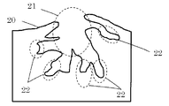
- FIG. 2 shows a schematic view of the pore structure of activated carbon.
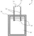
- FIG. 1 shows a schematic view of a heat storage device 10 according to an embodiment.
- the heat storage device 10 includes a heat storage tank 11 filled with a heat storage material 12, a pair of electrodes 13 including a first electrode 13 a and a second electrode 13 b, a DC power supply 14, and a switch 15.
- the heat storage tank 11 is kept warm by a heat insulating material.
- An example of a thermal insulation is glass wool.
- the heat storage tank 11 contains a heat storage material 12.
- the heat storage material 12 is sodium acetate trihydrate.
- the heat storage material 12 contains sodium acetate trihydrate as a main component.
- Heat storage material 12 The heat storage material 12 contains an inorganic porous body.
- the present inventors believe that the inside of the pores of the inorganic porous body has a fine solid heat storage material 12.
- the fine solid heat storage material 12 is also referred to as a "cluster".
- the fine solid heat storage material 12 contained in the pores has stronger intermolecular bonding than the heat storage material 12 located outside the pores due to capillary condensation.
- the heat storage material 12 when the heat storage material 12 is heated, the heat storage material 12 contained in the pores melts more slowly than the heat storage material 12 located outside the pores. As a result, it is possible to enhance the viability of the cluster after the heat storage material 12 is held at a high temperature in the liquid state. Therefore, even after the heat storage material 12 is held at a high temperature in the liquid state, the application of the voltage can cancel the supercooling state of sodium acetate trihydrate at a temperature of 58 ° C. or less.
- the cluster that is, the fine heat storage material 12 in the solid phase
- the heat storage material 12 crystallizes so as to spread from the center of the cluster to its periphery when a voltage is applied at the point.
- the crystallization of the heat storage material 12 at the time of application of the voltage in the subcooling state is based on the cluster.
- the inorganic porous body contained in the heat storage material 12 has an average pore diameter of 50 nanometers or less.
- the pore size of the inorganic porous material can be measured by a commonly used method. For example, the pore size can be calculated based on a nitrogen gas adsorption method or a mercury intrusion method.
- the term "average pore size” refers to the adsorption isotherm of nitrogen by the Barret-Joyner-Halenda method (hereinafter referred to as "BJH method") or Horvath-Kawazoe method (hereinafter referred to as "HK method”).
- BJH method Barret-Joyner-Halenda method
- HK method Horvath-Kawazoe method
- the pore size distribution curve is drawn on the graph of the pore diameter on the horizontal axis and the pore volume on the vertical axis.
- the mean pore size is equal to the pore size at the maximum of the pore volume.
- the term "average pore size" as used herein means the pore size at the peak value of the pore size distribution curve determined by mercury porosimetry.
- the average pore size of zeolite, mesoporous silica or activated carbon is calculated by a nitrogen gas adsorption method.
- the average pore size of silica gel is calculated by mercury porosimetry.
- the average pore size of the commercially available inorganic porous material is disclosed in its catalog.
- the lower limit of the average pore size of the inorganic porous body is not limited as long as the inside of the pore has the heat storage material 12 and the melting of the cluster is suppressed.
- the average pore size of the inorganic porous body is 0.9 nm or more.
- the material of the inorganic porous body is, for example, metal oxide or carbon.
- metal oxides are zeolite, silica, alumina, titania or tungsten oxide.
- the desirable inorganic porous material is activated carbon or silica gel.
- Activated carbon and silica gel have pores having a size of 50 nm or less (hereinafter referred to as “micro mesopores”), and are connected to these pores and having a size larger than 50 nm (hereinafter , "Macropores”) on its surface.
- micro mesopores pores having a size of 50 nm or less
- Macropores pores having a size larger than 50 nm
- FIG. 2 shows a schematic view of the pore structure of the inorganic porous material.
- the activated carbon surface 20 has macropores 21.
- the micro mesopores 22 are arranged inside the activated carbon so as to be connected to the macropores 21. Therefore, the heat storage material 12 is easily introduced into the micro mesopores 22. In this manner, a fine solid heat storage material 12 is formed inside the micro mesopores. This will be described in detail later.
- heat storage material 12 can be disposed in micro mesopores 22 having a size of 50 nanometers or less, as compared with an inorganic porous body having no macropores 21 such as mesoporous silica.
- the cluster survival rate is further improved after the heat storage material 12 is held at a high temperature in the liquid state. For this reason, even if the heat storage material 12 is held at a high temperature for a long time in the liquid state, the subcooling can be canceled by voltage application.
- the heat storage material 12 may contain an additive.
- additives are supercooling release aids, viscosity modifiers, foam stabilizers, antioxidants, defoamers, abrasive grains, fillers, pigments, dyes, colorants, thickeners, surfactants, Flame retardants, plasticizers, lubricants, antistatic agents, heat stabilizers, tackifiers, curing catalysts, stabilizers, silane coupling agents, or waxes.
- the type and amount of additives are not limited as long as the object of the present invention is not hindered.
- the additive need not be added to the heat storage material 12.
- the method of forming the fine heat storage material 12 of the solid phase in the pores of the inorganic porous body will be described below.
- the heat storage material 12 containing an inorganic porous body is heated at a temperature equal to or higher than the melting point of the heat storage material 12 (that is, 58 degrees Celsius).
- the heat storage material 12 is in a liquid state.
- the heat storage material 12 is allowed to stand for a predetermined time while the temperature is maintained. During this time, the heat storage material 12 is introduced into the pores of the inorganic porous body.
- the present inventors believe that the heat storage material 12 is introduced into the pores of the inorganic porous body by capillary action.
- the heat storage material 12 is cooled at a temperature of minus 30 degrees Celsius or lower.
- the heat storage material 12 is cooled to 58 ° C. or lower, and after being subcooled, seed crystals made of sodium acetate trihydrate are added to the heat storage material 12.
- the heat storage material 12 in the pores is crystallized by cooling at a low temperature of minus 30 degrees Celsius or less or addition of seed crystals in a supercooled state. That is, the heat storage material 12 in the pore changes from the liquid phase to the solid phase. In this way, the fine heat storage material 12 of the solid phase can be formed in the pores of the inorganic porous body.
- the first electrode 13 a and the second electrode 13 b are electrically connected to the power supply 15 through the wiring and the switch 14.
- the first electrode 13 a and the second electrode 13 b are both arranged to be in contact with the heat storage material 12.
- the distance between the first electrode 13a and the second electrode 13b of the portion in contact with the heat storage material 12 is not particularly limited. An example of the distance is 1 mm or more and 30 mm or less.
- the first electrode 13a has silver, a silver alloy, or a silver compound on its surface. Needless to say, the silver or its alloy is in contact with the heat storage material 12. Examples of silver alloys are silver palladium alloys or silver copper alloys. Examples of silver compounds are silver halide or silver oxide. An example of silver halide is silver bromide.
- the second electrode 13b need not have silver, a silver alloy, or a silver compound on the surface thereof. It goes without saying that the second electrode 13b may also have silver, a silver alloy or a silver compound on its surface.
- the shapes of the first electrode 13a and the second electrode 13b are not limited.
- the shapes of the first electrode 13a and the second electrode 13b are, for example, plate-like or linear.
- an AC power supply may be used instead of the DC power supply 14.
- the heat storage device 10 may include a plurality of heat storage tanks 11.
- Each heat storage tank 11 may include a first electrode 13 a and a second electrode 13 b in contact with each heat storage material 12.
- the plurality of heat storage tanks 11 can be electrically connected in parallel to the DC power supply 14.
- the heat storage material 12 is cooled and brought into a subcooling state. In this way, the latent heat is stored in sodium acetate trihydrate.
- the heat storage device 12 After the heat storage material 12 releases heat, the heat storage device is heated at a temperature of 58 degrees Celsius or more and 80 degrees Celsius or less for repeated use. Thus, the sodium acetate trihydrate contained in the heat storage material 12 melts. In other words, the crystallized sodium acetate trihydrate (ie, solid state sodium acetate trihydrate) melts upon heating.
- the heat storage material 12 should not be heated to a temperature of 90 degrees Celsius or more. If the heat storage material 12 is heated at a temperature of 90 degrees centigrade or more, as shown in Comparative Example 4 to Comparative Example 12, the viability of the cluster is significantly reduced.
- the fine heat storage material 12 of solid phase may be formed again.
- Example 1 The first embodiment is configured of the first embodiment 1A to the first embodiment 1D.
- Example 1A (Preparation of heat storage device 10) To the thermal storage tank 11, sodium acetate (2.2 grams), water (1.8 grams), and a zeolite having an average pore size of 0.9 nanometers were added.
- the heat storage tank 11 was a glass sample bottle having a capacity of 9 ml.
- Zeolite was purchased from Tosoh Corporation under the trade name "X-type zeolite, F-9".
- the amount of zeolite added was 20% by mass based on the total weight of sodium acetate and water (ie, 4.0 grams). In other words, the amount of zeolite added was 0.8 grams.
- the heat storage material 12 containing zeolite and containing sodium acetate trihydrate as the main component was stored in the heat storage tank 11.
- the first electrode 13 a and the second electrode 13 b made of linear silver were dipped in the heat storage material 12.
- the first electrode 13a and the second electrode 13b had a diameter of 1.5 millimeters.
- the length of the portion where the first electrode 13a and the second electrode 13b are in contact with the heat storage material 12 was approximately 5 millimeters.
- the heat storage tank 11 was covered. Thus, the heat storage device 10 according to Example 1 was obtained.
- the liquid heat storage material 12 contained in the heat storage tank 11 was allowed to stand at a temperature of 70 degrees Celsius for 2 hours. The present inventors believe that the heat storage material 12 has entered into the pores of the zeolite during this time. Thereafter, the heat storage material 12 was cooled to minus 30 degrees Celsius. Thus, the heat storage material 12 was crystallized. The present inventors considered that the heat storage material 12 in the pores and the heat storage material 12 outside the pores also changed from the liquid state to the solid state.
- the heat storage material 12 contained in the heat storage tank 11 was heated at a temperature of 70 degrees Celsius for 1 hour. Thereby, the heat storage material 12 was melted.
- the heat storage material 12 was allowed to stand at a stationary temperature of 80 degrees Celsius for a stationary time of 15 minutes. Furthermore, the heat storage material 12 was cooled to room temperature (approximately 25 degrees Celsius). A voltage of 2 volts was applied for approximately 2 minutes between the first electrode 13a and the second electrode 13b, and the inventors visually observed whether the heat storage material 12 was crystallized. The evaluation was repeated six times. Table 1 shows the observation results.
- the fractional molecule included in Table 1 is the number of times the heat storage material 12 has been crystallized.
- the denominator of the fractions included in Table 1 is the number of evaluations (ie six times).
- Example 1B to 1D In Examples 1B-1D, the same experiment as Example 1A was conducted except that the standing time was 30 minutes, 1 hour and 2 hours, respectively. The experimental results are shown in Table 1.
- Example 2 The same experiment as Example 1 was conducted except for the following items (i) and (ii).
- mesoporous silica purchased from Sigma-Aldrich under the trade name “MCM-41”, average pore size: 2.5 nm to 3.0 nm
- MCM-41 average pore size: 2.5 nm to 3.0 nm
- the amount of mesoporous silica added was 15% by mass (ie, 0.6 gram) based on the total weight of sodium acetate and water (ie, 4.0 gram).
- Example 3 The same experiment as in Example 1 was conducted except for the following item (i).
- activated carbon purchased from Calgon Carbon Japan Co., Ltd. under the trade name “Ladhus activated carbon”, average pore diameter: 1.0 nm to 3.0 nm was used.
- Example 4 The same experiment as in Example 1 was conducted except for the following item (i).
- silica gel purchased from Fuji Silysia Chemical Co., Ltd. under the trade name “MB100”, average pore diameter: 10 nm was used.
- Example 5 The same experiment as in Example 1 was conducted except for the following item (i).
- silica gel purchased from Fuji Silysia Chemical Co., Ltd. under the trade name “MB300”, average pore diameter: 30 nm was used.
- Example 6 The same experiment as in Example 1 was conducted except for the following item (i).
- silica gel purchased from Fuji Silysia Chemical Co., Ltd. under the trade name “MB500”, average pore diameter: 50 nm was used.
- Example 1 The same experiment as in Example 1 was conducted except that the zeolite was not added to the heat storage tank 11.
- silica gel purchased from Fuji Silysia Chemical Co., Ltd. under the trade name “MB800”, average pore diameter: 80 nm was used.
- silica purchased from Kanto Chemical Co., Ltd.
- the silica was formed from non-porous amorphous silicon dioxide.
- the standing temperature needs to be 80 degrees Celsius or less. Otherwise, crystallization of the heat storage material 12 often fails.
- the average pore size needs to be 50 nm or less. Otherwise, crystallization of the heat storage material 12 often fails.
- the inorganic porous material is preferably silica gel or activated carbon.
- the heat storage material 12 has a melting point (that is, 58 degrees Celsius or higher) and 80 degrees Celsius by adding an inorganic porous material having an average pore diameter of 50 nanometers or less to the heat storage material 12. Even after the temperature is maintained at a high temperature below, it is possible to extract latent heat by voltage application.
- the latent heat can be extracted by the application of the voltage.
- the heat storage device according to the present invention is attached to a vehicle equipped with an engine that drives wheels.
- the heat released from the heat storage material 12 is used to warm up an internal combustion engine such as an engine provided in a vehicle.
- the heat storage device according to the present invention is also attached to a boiler, an air conditioner or a water heater.
Landscapes
- Engineering & Computer Science (AREA)
- Chemical & Material Sciences (AREA)
- Thermal Sciences (AREA)
- Physics & Mathematics (AREA)
- Combustion & Propulsion (AREA)
- Mechanical Engineering (AREA)
- General Engineering & Computer Science (AREA)
- Materials Engineering (AREA)
- Chemical Kinetics & Catalysis (AREA)
- Organic Chemistry (AREA)
- Dispersion Chemistry (AREA)
- Secondary Cells (AREA)
- Electric Double-Layer Capacitors Or The Like (AREA)
Priority Applications (2)
| Application Number | Priority Date | Filing Date | Title |
|---|---|---|---|
| EP18822641.9A EP3647708B1 (en) | 2017-06-29 | 2018-03-26 | Method for releasing heat |
| US16/667,946 US11268003B2 (en) | 2017-06-29 | 2019-10-30 | Heat storage device |
Applications Claiming Priority (2)
| Application Number | Priority Date | Filing Date | Title |
|---|---|---|---|
| JP2017126876A JP6733615B2 (ja) | 2017-06-29 | 2017-06-29 | 蓄熱装置 |
| JP2017-126876 | 2017-06-29 |
Related Child Applications (1)
| Application Number | Title | Priority Date | Filing Date |
|---|---|---|---|
| US16/667,946 Continuation US11268003B2 (en) | 2017-06-29 | 2019-10-30 | Heat storage device |
Publications (1)
| Publication Number | Publication Date |
|---|---|
| WO2019003523A1 true WO2019003523A1 (ja) | 2019-01-03 |
Family
ID=64741410
Family Applications (1)
| Application Number | Title | Priority Date | Filing Date |
|---|---|---|---|
| PCT/JP2018/011975 Ceased WO2019003523A1 (ja) | 2017-06-29 | 2018-03-26 | 蓄熱装置 |
Country Status (4)
| Country | Link |
|---|---|
| US (1) | US11268003B2 (enExample) |
| EP (1) | EP3647708B1 (enExample) |
| JP (1) | JP6733615B2 (enExample) |
| WO (1) | WO2019003523A1 (enExample) |
Cited By (1)
| Publication number | Priority date | Publication date | Assignee | Title |
|---|---|---|---|---|
| WO2023162972A1 (ja) * | 2022-02-24 | 2023-08-31 | パナソニックホールディングス株式会社 | 蓄冷材 |
Families Citing this family (1)
| Publication number | Priority date | Publication date | Assignee | Title |
|---|---|---|---|---|
| EP4102167B1 (en) * | 2021-06-07 | 2024-01-31 | GGD Global Green Developer APS | A thermal system for thermal energy storage |
Citations (9)
| Publication number | Priority date | Publication date | Assignee | Title |
|---|---|---|---|---|
| JPS60243189A (ja) * | 1984-05-17 | 1985-12-03 | Nok Corp | 蓄熱材 |
| JPS61204293A (ja) | 1985-03-07 | 1986-09-10 | Hitachi Chem Co Ltd | 蓄熱槽 |
| JPH0596769U (ja) * | 1991-08-01 | 1993-12-27 | エヌオーケー株式会社 | 過冷却液体の発核装置 |
| JPH06117787A (ja) * | 1992-10-05 | 1994-04-28 | Mitsubishi Motors Corp | 蓄熱装置 |
| JPH09143461A (ja) * | 1995-11-24 | 1997-06-03 | Toyota Central Res & Dev Lab Inc | 蓄熱材 |
| JP2008020177A (ja) | 2006-06-15 | 2008-01-31 | Matsushita Electric Ind Co Ltd | 蓄熱システム |
| JP2012078030A (ja) * | 2010-10-04 | 2012-04-19 | Honda Motor Co Ltd | 蓄熱装置 |
| JP2013067720A (ja) | 2011-09-22 | 2013-04-18 | Panasonic Corp | 過冷却防止剤、蓄熱方法及び蓄熱システム |
| JP2016044917A (ja) * | 2014-08-25 | 2016-04-04 | 株式会社東芝 | 蓄熱装置 |
Family Cites Families (25)
| Publication number | Priority date | Publication date | Assignee | Title |
|---|---|---|---|---|
| US3806433A (en) * | 1966-04-04 | 1974-04-23 | I Diller | Method and apparatus for the activation of an electrolytic cell |
| DE2731572C3 (de) * | 1977-07-13 | 1980-09-18 | Philips Patentverwaltung Gmbh, 2000 Hamburg | Wärmespeichermittel |
| US4248291A (en) * | 1978-10-18 | 1981-02-03 | Seymour Jarmul | Compact thermal energy reservoirs |
| US4491172A (en) * | 1981-04-22 | 1985-01-01 | Thermal Energy Storage, Inc. | Energy storage apparatus |
| US4529488A (en) * | 1982-06-29 | 1985-07-16 | Nippon Gohsei Kagaku Kogyo Kabushiki Kaisha | Process for depositing salts |
| FR2569418B1 (fr) * | 1984-08-27 | 1986-12-05 | Solvay | Composition a base de chlorure de calcium hexahydrate pour le stockage de calories par changement de phase et procede pour sa preparation |
| JPH0239175Y2 (enExample) | 1986-02-20 | 1990-10-22 | ||
| JPS63116073A (ja) * | 1986-10-31 | 1988-05-20 | 株式会社東芝 | 蓄熱式ヒ−トポンプ |
| JPH0760075B2 (ja) * | 1987-01-31 | 1995-06-28 | 株式会社東芝 | 蓄熱装置 |
| US4949549A (en) * | 1987-07-07 | 1990-08-21 | International Thermal Packaging, Inc. | Cooling device with improved waste-heat handling capability |
| US5378337A (en) * | 1992-05-12 | 1995-01-03 | Nok Corporation | Electrical nucleation device for supercooled heat storage medium |
| JP2943609B2 (ja) * | 1994-06-21 | 1999-08-30 | トヨタ自動車株式会社 | 蓄熱装置 |
| GB9514252D0 (en) * | 1995-07-12 | 1995-09-13 | Univ Strathclyde | Mouldable product |
| CA2208695C (en) * | 1996-06-25 | 2007-03-20 | Kenji Saita | Heat storage system and heat release control method |
| JP3588630B2 (ja) * | 2000-09-06 | 2004-11-17 | 独立行政法人産業技術総合研究所 | 蓄熱式加熱体 |
| JP4175388B2 (ja) * | 2006-06-05 | 2008-11-05 | トヨタ自動車株式会社 | 蓄熱装置及びエンジン |
| DE202011002156U1 (de) * | 2011-01-31 | 2011-05-26 | Promat GmbH, 40878 | Latentwärmespeicher |
| JP5670853B2 (ja) * | 2011-09-27 | 2015-02-18 | 株式会社東芝 | 空調システム |
| US9410747B2 (en) * | 2011-12-06 | 2016-08-09 | Korea Institute Of Construction Technology | Porous material having micropores capable of storing and releasing heat by phase change and preparation method thereof |
| JP5875532B2 (ja) | 2013-01-15 | 2016-03-02 | 三菱電機株式会社 | 蓄熱装置 |
| US20150241136A1 (en) * | 2014-02-21 | 2015-08-27 | Panasonic Intellectual Property Management Co., Ltd. | Heat storage device and method of using latent heat storage material |
| US10161688B2 (en) * | 2014-04-02 | 2018-12-25 | Panasonic Intellectual Property Management Co., Ltd. | Heat storage apparatus, method for storing heat, and method for producing heat storage apparatus |
| JP2016006370A (ja) * | 2014-05-29 | 2016-01-14 | パナソニックIpマネジメント株式会社 | 潜熱蓄熱材における結晶核形成方法及び蓄熱装置 |
| JP6590607B2 (ja) * | 2014-09-29 | 2019-10-16 | パナソニック株式会社 | 蓄熱材組成物、蓄熱装置及び蓄熱方法 |
| JP2017053528A (ja) | 2015-09-08 | 2017-03-16 | 株式会社東芝 | 蓄熱装置、過冷却解除装置 |
-
2017
- 2017-06-29 JP JP2017126876A patent/JP6733615B2/ja active Active
-
2018
- 2018-03-26 EP EP18822641.9A patent/EP3647708B1/en active Active
- 2018-03-26 WO PCT/JP2018/011975 patent/WO2019003523A1/ja not_active Ceased
-
2019
- 2019-10-30 US US16/667,946 patent/US11268003B2/en active Active
Patent Citations (9)
| Publication number | Priority date | Publication date | Assignee | Title |
|---|---|---|---|---|
| JPS60243189A (ja) * | 1984-05-17 | 1985-12-03 | Nok Corp | 蓄熱材 |
| JPS61204293A (ja) | 1985-03-07 | 1986-09-10 | Hitachi Chem Co Ltd | 蓄熱槽 |
| JPH0596769U (ja) * | 1991-08-01 | 1993-12-27 | エヌオーケー株式会社 | 過冷却液体の発核装置 |
| JPH06117787A (ja) * | 1992-10-05 | 1994-04-28 | Mitsubishi Motors Corp | 蓄熱装置 |
| JPH09143461A (ja) * | 1995-11-24 | 1997-06-03 | Toyota Central Res & Dev Lab Inc | 蓄熱材 |
| JP2008020177A (ja) | 2006-06-15 | 2008-01-31 | Matsushita Electric Ind Co Ltd | 蓄熱システム |
| JP2012078030A (ja) * | 2010-10-04 | 2012-04-19 | Honda Motor Co Ltd | 蓄熱装置 |
| JP2013067720A (ja) | 2011-09-22 | 2013-04-18 | Panasonic Corp | 過冷却防止剤、蓄熱方法及び蓄熱システム |
| JP2016044917A (ja) * | 2014-08-25 | 2016-04-04 | 株式会社東芝 | 蓄熱装置 |
Cited By (1)
| Publication number | Priority date | Publication date | Assignee | Title |
|---|---|---|---|---|
| WO2023162972A1 (ja) * | 2022-02-24 | 2023-08-31 | パナソニックホールディングス株式会社 | 蓄冷材 |
Also Published As
| Publication number | Publication date |
|---|---|
| US11268003B2 (en) | 2022-03-08 |
| EP3647708A4 (en) | 2020-07-15 |
| EP3647708B1 (en) | 2021-07-21 |
| US20200063012A1 (en) | 2020-02-27 |
| EP3647708A1 (en) | 2020-05-06 |
| JP6733615B2 (ja) | 2020-08-05 |
| JP2019011874A (ja) | 2019-01-24 |
Similar Documents
| Publication | Publication Date | Title |
|---|---|---|
| JP5003213B2 (ja) | 蓄熱剤、包接水和物の蓄熱速度を増加させる方法 | |
| WO2019003523A1 (ja) | 蓄熱装置 | |
| US10921064B2 (en) | Heat storage apparatus, method for storing heat, and method for producing heat storage apparatus | |
| JP2016108535A (ja) | 蓄熱材組成物、蓄熱装置及び蓄熱方法 | |
| TW200804176A (en) | Methods for hydrogen storage and refrigeration | |
| CN104531077A (zh) | 膨胀石墨基水合盐复合固-固相变储能材料的制备方法 | |
| WO2021000439A1 (zh) | 相变储热硅胶、制备方法及其应用 | |
| JP2018059676A (ja) | 蓄熱装置 | |
| JP2017078163A (ja) | 潜熱蓄冷材 | |
| US20150153110A1 (en) | Heat storage material composition, and auxiliary heat source and heat supply method using the same | |
| JP2013067720A (ja) | 過冷却防止剤、蓄熱方法及び蓄熱システム | |
| JP2019196867A (ja) | 蓄熱方法および蓄熱装置 | |
| JP5660949B2 (ja) | 蓄熱材組成物 | |
| JP5573193B2 (ja) | 蓄熱材組成物 | |
| JP2019011874A5 (enExample) | ||
| JP4394594B2 (ja) | シリコーン液入り静止誘導器 | |
| US4604223A (en) | Heat storage material | |
| JP2007314741A (ja) | 潜熱蓄熱材組成物 | |
| JP2009051905A (ja) | 包接水和物を生成する性質を有する水溶液、第四級アンモニウム塩をゲスト化合物とする包接水和物及び当該包接水和物のスラリ並びに、包接水和物の生成方法、包接水和物が生成又は成長する速度を増加させる方法及び包接水和物が生成又は成長する際に起こる過冷却現象を防止又は抑制する方法 | |
| JP2019207055A (ja) | 蓄熱方法および蓄熱装置 | |
| JP7422132B2 (ja) | 蓄熱材組成物及び蓄熱装置 | |
| JP2017036438A (ja) | 潜熱蓄熱材 | |
| JP2019074246A (ja) | 蓄熱装置 | |
| JP3880677B2 (ja) | 潜熱蓄熱材組成物 | |
| JP5590102B2 (ja) | 包接水和物の蓄熱速度の増加方法、包接水和物が生成又は成長する速度の増加方法、包接水和物及び包接水和物のスラリ |
Legal Events
| Date | Code | Title | Description |
|---|---|---|---|
| 121 | Ep: the epo has been informed by wipo that ep was designated in this application |
Ref document number: 18822641 Country of ref document: EP Kind code of ref document: A1 |
|
| NENP | Non-entry into the national phase |
Ref country code: DE |
|
| ENP | Entry into the national phase |
Ref document number: 2018822641 Country of ref document: EP Effective date: 20200129 |