WO2018203522A1 - 蓄電デバイス用組成物およびこの蓄電デバイス用組成物を用いた蓄電デバイス用セパレータおよび蓄電デバイス - Google Patents
蓄電デバイス用組成物およびこの蓄電デバイス用組成物を用いた蓄電デバイス用セパレータおよび蓄電デバイス Download PDFInfo
- Publication number
- WO2018203522A1 WO2018203522A1 PCT/JP2018/017185 JP2018017185W WO2018203522A1 WO 2018203522 A1 WO2018203522 A1 WO 2018203522A1 JP 2018017185 W JP2018017185 W JP 2018017185W WO 2018203522 A1 WO2018203522 A1 WO 2018203522A1
- Authority
- WO
- WIPO (PCT)
- Prior art keywords
- storage device
- composition
- power storage
- electricity storage
- separator
- Prior art date
- Legal status (The legal status is an assumption and is not a legal conclusion. Google has not performed a legal analysis and makes no representation as to the accuracy of the status listed.)
- Ceased
Links
Images


Classifications
-
- C—CHEMISTRY; METALLURGY
- C01—INORGANIC CHEMISTRY
- C01G—COMPOUNDS CONTAINING METALS NOT COVERED BY SUBCLASSES C01D OR C01F
- C01G23/00—Compounds of titanium
- C01G23/003—Titanates
- C01G23/005—Alkali titanates
-
- H—ELECTRICITY
- H01—ELECTRIC ELEMENTS
- H01M—PROCESSES OR MEANS, e.g. BATTERIES, FOR THE DIRECT CONVERSION OF CHEMICAL ENERGY INTO ELECTRICAL ENERGY
- H01M50/00—Constructional details or processes of manufacture of the non-active parts of electrochemical cells other than fuel cells, e.g. hybrid cells
- H01M50/40—Separators; Membranes; Diaphragms; Spacing elements inside cells
- H01M50/409—Separators, membranes or diaphragms characterised by the material
- H01M50/431—Inorganic material
-
- H—ELECTRICITY
- H01—ELECTRIC ELEMENTS
- H01G—CAPACITORS; CAPACITORS, RECTIFIERS, DETECTORS, SWITCHING DEVICES, LIGHT-SENSITIVE OR TEMPERATURE-SENSITIVE DEVICES OF THE ELECTROLYTIC TYPE
- H01G11/00—Hybrid capacitors, i.e. capacitors having different positive and negative electrodes; Electric double-layer [EDL] capacitors; Processes for the manufacture thereof or of parts thereof
- H01G11/52—Separators
-
- H—ELECTRICITY
- H01—ELECTRIC ELEMENTS
- H01M—PROCESSES OR MEANS, e.g. BATTERIES, FOR THE DIRECT CONVERSION OF CHEMICAL ENERGY INTO ELECTRICAL ENERGY
- H01M10/00—Secondary cells; Manufacture thereof
- H01M10/05—Accumulators with non-aqueous electrolyte
- H01M10/052—Li-accumulators
- H01M10/0525—Rocking-chair batteries, i.e. batteries with lithium insertion or intercalation in both electrodes; Lithium-ion batteries
-
- H—ELECTRICITY
- H01—ELECTRIC ELEMENTS
- H01M—PROCESSES OR MEANS, e.g. BATTERIES, FOR THE DIRECT CONVERSION OF CHEMICAL ENERGY INTO ELECTRICAL ENERGY
- H01M10/00—Secondary cells; Manufacture thereof
- H01M10/42—Methods or arrangements for servicing or maintenance of secondary cells or secondary half-cells
- H01M10/52—Removing gases inside the secondary cell, e.g. by absorption
-
- H—ELECTRICITY
- H01—ELECTRIC ELEMENTS
- H01M—PROCESSES OR MEANS, e.g. BATTERIES, FOR THE DIRECT CONVERSION OF CHEMICAL ENERGY INTO ELECTRICAL ENERGY
- H01M4/00—Electrodes
- H01M4/02—Electrodes composed of, or comprising, active material
- H01M4/36—Selection of substances as active materials, active masses, active liquids
- H01M4/48—Selection of substances as active materials, active masses, active liquids of inorganic oxides or hydroxides
- H01M4/485—Selection of substances as active materials, active masses, active liquids of inorganic oxides or hydroxides of mixed oxides or hydroxides for inserting or intercalating light metals, e.g. LiTi2O4 or LiTi2OxFy
-
- H—ELECTRICITY
- H01—ELECTRIC ELEMENTS
- H01M—PROCESSES OR MEANS, e.g. BATTERIES, FOR THE DIRECT CONVERSION OF CHEMICAL ENERGY INTO ELECTRICAL ENERGY
- H01M50/00—Constructional details or processes of manufacture of the non-active parts of electrochemical cells other than fuel cells, e.g. hybrid cells
- H01M50/40—Separators; Membranes; Diaphragms; Spacing elements inside cells
- H01M50/489—Separators, membranes, diaphragms or spacing elements inside the cells, characterised by their physical properties, e.g. swelling degree, hydrophilicity or shut down properties
- H01M50/491—Porosity
-
- C—CHEMISTRY; METALLURGY
- C01—INORGANIC CHEMISTRY
- C01P—INDEXING SCHEME RELATING TO STRUCTURAL AND PHYSICAL ASPECTS OF SOLID INORGANIC COMPOUNDS
- C01P2002/00—Crystal-structural characteristics
- C01P2002/70—Crystal-structural characteristics defined by measured X-ray, neutron or electron diffraction data
- C01P2002/72—Crystal-structural characteristics defined by measured X-ray, neutron or electron diffraction data by d-values or two theta-values, e.g. as X-ray diagram
-
- C—CHEMISTRY; METALLURGY
- C01—INORGANIC CHEMISTRY
- C01P—INDEXING SCHEME RELATING TO STRUCTURAL AND PHYSICAL ASPECTS OF SOLID INORGANIC COMPOUNDS
- C01P2002/00—Crystal-structural characteristics
- C01P2002/70—Crystal-structural characteristics defined by measured X-ray, neutron or electron diffraction data
- C01P2002/74—Crystal-structural characteristics defined by measured X-ray, neutron or electron diffraction data by peak-intensities or a ratio thereof only
-
- C—CHEMISTRY; METALLURGY
- C01—INORGANIC CHEMISTRY
- C01P—INDEXING SCHEME RELATING TO STRUCTURAL AND PHYSICAL ASPECTS OF SOLID INORGANIC COMPOUNDS
- C01P2006/00—Physical properties of inorganic compounds
- C01P2006/12—Surface area
-
- C—CHEMISTRY; METALLURGY
- C01—INORGANIC CHEMISTRY
- C01P—INDEXING SCHEME RELATING TO STRUCTURAL AND PHYSICAL ASPECTS OF SOLID INORGANIC COMPOUNDS
- C01P2006/00—Physical properties of inorganic compounds
- C01P2006/40—Electric properties
-
- C—CHEMISTRY; METALLURGY
- C01—INORGANIC CHEMISTRY
- C01P—INDEXING SCHEME RELATING TO STRUCTURAL AND PHYSICAL ASPECTS OF SOLID INORGANIC COMPOUNDS
- C01P2006/00—Physical properties of inorganic compounds
- C01P2006/60—Optical properties, e.g. expressed in CIELAB-values
- C01P2006/62—L* (lightness axis)
-
- H—ELECTRICITY
- H01—ELECTRIC ELEMENTS
- H01G—CAPACITORS; CAPACITORS, RECTIFIERS, DETECTORS, SWITCHING DEVICES, LIGHT-SENSITIVE OR TEMPERATURE-SENSITIVE DEVICES OF THE ELECTROLYTIC TYPE
- H01G11/00—Hybrid capacitors, i.e. capacitors having different positive and negative electrodes; Electric double-layer [EDL] capacitors; Processes for the manufacture thereof or of parts thereof
- H01G11/04—Hybrid capacitors
- H01G11/06—Hybrid capacitors with one of the electrodes allowing ions to be reversibly doped thereinto, e.g. lithium ion capacitors [LIC]
-
- H—ELECTRICITY
- H01—ELECTRIC ELEMENTS
- H01M—PROCESSES OR MEANS, e.g. BATTERIES, FOR THE DIRECT CONVERSION OF CHEMICAL ENERGY INTO ELECTRICAL ENERGY
- H01M50/00—Constructional details or processes of manufacture of the non-active parts of electrochemical cells other than fuel cells, e.g. hybrid cells
- H01M50/40—Separators; Membranes; Diaphragms; Spacing elements inside cells
- H01M50/409—Separators, membranes or diaphragms characterised by the material
- H01M50/449—Separators, membranes or diaphragms characterised by the material having a layered structure
-
- Y—GENERAL TAGGING OF NEW TECHNOLOGICAL DEVELOPMENTS; GENERAL TAGGING OF CROSS-SECTIONAL TECHNOLOGIES SPANNING OVER SEVERAL SECTIONS OF THE IPC; TECHNICAL SUBJECTS COVERED BY FORMER USPC CROSS-REFERENCE ART COLLECTIONS [XRACs] AND DIGESTS
- Y02—TECHNOLOGIES OR APPLICATIONS FOR MITIGATION OR ADAPTATION AGAINST CLIMATE CHANGE
- Y02E—REDUCTION OF GREENHOUSE GAS [GHG] EMISSIONS, RELATED TO ENERGY GENERATION, TRANSMISSION OR DISTRIBUTION
- Y02E60/00—Enabling technologies; Technologies with a potential or indirect contribution to GHG emissions mitigation
- Y02E60/10—Energy storage using batteries
Definitions
- the present invention relates to a composition used for an electricity storage device such as a lithium ion battery or an electric double layer capacitor. Specifically, by using lithium titanate (Li 2 TiO 3 ) having a specific peak ratio as a main component, it is possible to develop conductivity due to blue discoloration (reduction) even when used in a reducing atmosphere as compared with conventional lithium compounds.
- the present invention relates to a composition for an electricity storage device that can be suppressed.
- the carbon dioxide in use or over time which has been a problem in conventional power storage devices, is not deteriorated without deteriorating battery characteristics.
- the present invention relates to an electricity storage device separator and an electricity storage device that can suppress generation of various gases such as gas, hydrogen gas, and fluorine gas.
- (HF) is further dissociated Protons (H + ) generated by And when such protons couple
- BF 4 decomposed from the electrolyte - is carbon dioxide and the anions and the unreacted lithium carbonate, such as produced by reactions - or PF 6.
- Patent Documents 1 to 3 gas absorbing materials mainly composed of various compounds (mainly lithium compounds) have been developed to absorb the gas generated from the past.
- Patent Document 1 describes that lithium composite oxide is used as an absorbent for carbon dioxide gas, and zeolite is used as an absorbent for hydrogen gas (claims 2, 3 and 3 of Patent Document 1). [0012] to [0014]).
- Patent Document 2 describes that lithium hydroxide is used as an absorbent material such as carbon dioxide gas or hydrogen gas (see claims 3 and [0009] and [0010] of Patent Document 2).
- Patent Document 3 describes the use of an alkaline earth metal carbonate as a fluorine gas absorber (see claims 1, 3, 4 and [0014] of Patent Document 3).
- Patent Literature 4 describes a carbon dioxide gas absorbent in which lithium carbonate powder, lithium oxide powder, and titanium dioxide powder are mixed at a specific ratio (see claim 1 and [0028] of Patent Literature 4),
- Non-Patent Document 1 discloses that lithium composite oxide can be a carbon dioxide absorbing material (see “Features of New CO 2 Absorbing Material” on page 12 of Non-Patent Document 1).
- lithium compounds move as lithium ions in the electricity storage device, lithium compounds such as those described in Patent Documents 1 to 4 are present in the vicinity of the negative electrode or on the negative electrode side.
- a lithium compound is used as a material for the separator, it is used in such a form that it is arranged and applied on the positive electrode side (a form that is not exposed on the negative electrode side). There is a problem that the process becomes complicated.
- the present invention has been made in view of the above-described conventional problems, and an object of the present invention is to provide a composition for an electricity storage device that can suppress the expression of conductivity due to blue discoloration (reduction). . It is another object of the present invention to provide a separator for an electricity storage device and an electricity storage device using the composition for an electricity storage device.
- the main component is Li 2 TiO 3 having an intensity ratio (A / B) of the peak intensity (B) of 43.7 ⁇ 0.1 ° of 1.10 or more.
- the electrical storage device separator according to the present invention is characterized by using the electrical storage device composition of the present invention.
- the electrical storage device according to the present invention is characterized by using the electrical storage device separator of the present invention.
- composition for an electrical storage device it is possible to obtain an electrical storage device composition capable of suppressing the expression of conductivity due to blue discoloration (reduction) even when used in a reducing atmosphere as compared with a conventional lithium compound. Can do.
- lithium titanate having a specific peak ratio As a main component, without deteriorating the performance of the electricity storage device (while reducing the leakage current), it has been a problem in use or over time, which has been a problem in conventional electricity storage devices.
- An electricity storage device that can suppress generation of various gases such as carbon dioxide gas, hydrogen gas, and fluorine gas in the change can be obtained.
- the lithium ion of the composition for an electricity storage device of the present invention and a proton generated in the electricity storage device undergo an ion exchange reaction, thereby becoming a source of gas generation.
- the proton (H + ) itself can be captured.
- the titanate ion and carbonate ion of the gas composition for an electricity storage device of the present invention undergo an ion exchange reaction, whereby carbon dioxide gas can also be captured.
- composition for an electricity storage device of the present invention is used for a separator of an electricity storage device, even if the composition for an electricity storage device of the present invention is somewhat exposed on the negative electrode side of the separator (the conventional separator) Thus, an electric storage device capable of suppressing generation of various gases without deteriorating battery characteristics without strict production control such that the lithium compound is not exposed to the negative electrode side) is obtained. Can do.
- Li 2 in which the intensity ratio (A / B) of the peak intensity (A) of 4 ⁇ 0.1 ° and the peak intensity (B) of 2 ⁇ (diffraction angle) 43.7 ⁇ 0.1 ° is 1.10 or more.
- TiO 3 is the main component.
- the composition for an electricity storage device according to the present invention has a blue peak (reduction) even when used in a reducing atmosphere as compared with a conventional lithium compound by using Li 2 TiO 3 having a specific peak ratio as a main component. It is possible to suppress the expression of electrical conductivity due to.
- lithium titanate is usually manufactured (synthesized) by mixing and firing a Li source and a Ti source as raw materials, not only Li 2 TiO 3 but also a spinel type (Li 4 Ti 5 O). 12 ) and ramsdellite type (LiTi 2 O 4 : 124 type, Li 2 Ti 3 O 7 , 237 type) and other various structures are also synthesized. Therefore, the “main component” in the present invention is based on lithium titanate having a composition of Li 2 TiO 3 even when lithium titanate having various structures is contained as described above. I mean. Specifically, the lithium titanate content having a composition of Li 2 TiO 3 is 70% or more. Furthermore, 90% or more is more preferable, and 95% or more is most preferable.
- Intensity ratio (A / B) where 2 ⁇ (diffraction angle) 43.7 ⁇ 0.1 °, which is a characteristic peak of the 113 plane in the crystal structure of Li 2 TiO 3 , is B.
- the main component is Li 2 TiO 3 which is 1.10 or more.
- the composition for an electricity storage device of the present invention has a feature of Li 2 TiO 3 grown in the 002 plane direction, and therefore has conductivity due to blue discoloration (reduction) even when used in a reducing atmosphere as compared with a conventional lithium compound. Can be suppressed.
- the peak intensity ratio (A / B) is 1.10 or more
- the upper limit is not particularly limited.
- the upper limit of the peak intensity ratio (A / B) is preferably 1.50.
- the peak intensity ratio (A / B) is preferably 1.10 to 1.33.
- Li source It does not specifically limit about Li source used as the raw material of the composition for electrical storage devices of this invention, Various lithium sources, such as lithium carbonate, lithium hydroxide, lithium nitrate, can be used. Among them, it is preferable to use lithium hydroxide because it is easy to produce the composition for an electricity storage device having a specific peak intensity of the present invention.
- Ti source used as a raw material for the composition for an electricity storage device of the present invention is not particularly limited as in the case of the Li source.
- Various titanic acid compounds such as metatitanic acid, anatase type or rutile type titanium oxide, titanium chloride
- Various Ti sources such as titanium sulfate and titanyl sulfate can be used.
- anatase type titanium oxide because it is easy to produce the composition for an electricity storage device having a specific peak intensity of the present invention.
- the water content in the crystal structure is preferably less than 25 wt%, more preferably less than 15 wt%, and most preferably less than 10 wt%.
- the use of titanium oxide having a water content in the crystal structure of 25 wt% or more is not preferable because it is difficult to produce the composition for an electricity storage device having a specific peak intensity according to the present invention.
- the moisture content in the crystal structure means a weight reduction rate in a temperature range of 100 ° C. to 400 ° C. in thermogravimetric analysis (TG).
- the electrical storage device composition of the present invention can suppress the expression of conductivity due to reduction by setting a specific peak ratio, it exhibits a characteristic hue.
- the composition for an electricity storage device of the present invention is suppressed from blue discoloration before and after charging.
- the lightness (L value) is 80 or more. Among them, those showing lightness (L value) of 82 to 93 are preferable.
- Li / Ti (molar ratio) is essential, and Li / Ti (molar ratio) Is preferably 1.85 or more and 2.10 or less. More preferably, it is 1.90 or more and 2.05 or less, Most preferably, it is 1.95 or more and 2.00 or less.
- the composition for an electricity storage device according to the present invention can be used as a material for an electricity storage device such as a lithium ion battery or an electric double layer capacitor, specifically as a material for a positive electrode or a separator.
- an electricity storage device such as a lithium ion battery or an electric double layer capacitor
- a separator material when used as a separator material, it is not necessary to form and apply on the positive electrode side as before, and there is a merit that it is not necessary to employ a complicated manufacturing process. .
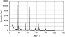
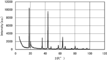
- 1 is an X-ray diffraction chart of a composition for an electricity storage device according to Example 1.
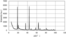
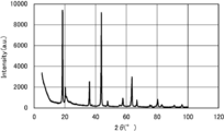
- 3 is an X-ray diffraction chart of a composition for an electricity storage device according to Example 2.
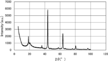
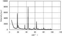
- 4 is an X-ray diffraction chart of a composition for an electricity storage device according to Example 3.
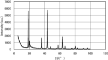
- 3 is an X-ray diffraction chart of a composition for an electricity storage device according to Comparative Example 1.
- 6 is an X-ray diffraction chart of a composition for an electricity storage device according to Comparative Example 2.
- 4 is an X-ray diffraction chart of a composition for an electricity storage device according to Comparative Example 3.
- 6 is an X-ray diffraction chart of a composition for an electricity storage device according to Comparative Example 4.
- 6 is an X-ray diffraction chart of a composition for an electricity storage device according to Comparative Example 5.
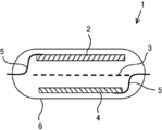
- 10 is an X-ray diffraction chart of a composition for an electricity storage device according to Comparative Example 6. It is a schematic diagram which shows the structure of the produced electrical storage device.
- composition for an electricity storage device of the present invention will be described in detail based on Examples and Comparative Examples.
- this invention is not limited to a following example.
- Example 1 First, 300 g of anatase-type titanium oxide (AMT-100 manufactured by Teika) adjusted to a water content of 9 wt% and 266 g of lithium hydroxide were wet mixed. At this time, Li / Ti (molar ratio) was 1.98. Then, by 2hr calcined at 750 ° C. in air to prepare a storage device for the composition of Example 1 mainly composed of 213-type lithium titanate (Li 2 TiO 3).
- AMT-100 anatase-type titanium oxide
- Li / Ti molar ratio
- Example 2 A composition for an electricity storage device of Example 2 containing 213 type lithium titanate (Li 2 TiO 3 ) as a main component was produced in the same manner as in Example 1 except that the firing temperature was 850 ° C.
- Example 3 A composition for an electricity storage device of Example 3 containing 213 type lithium titanate (Li 2 TiO 3 ) as a main component was prepared in the same manner as Example 1 except that the firing temperature was 650 ° C.
- Comparative Example 1 A composition for an electricity storage device of Comparative Example 1 containing 213 type lithium titanate (Li 2 TiO 3 ) as a main component was produced in the same manner as in Example 1 except that the firing temperature was 550 ° C.
- Comparative Example 2 A composition for an electricity storage device of Comparative Example 2 containing 213 type lithium titanate (Li 2 TiO 3 ) as a main component was produced in the same manner as in Example 1 except that the firing temperature was 450 ° C.
- Comparative Example 3 The composition for an electricity storage device of Comparative Example 3 containing 213 type lithium titanate (Li 2 TiO 3 ) as a main component was the same as Example 1 except that Li / Ti (molar ratio) was 1.84. Produced.
- Comparative Example 4 A composition for an electricity storage device of Comparative Example 4 was produced in the same manner as in Example 1 except that Li / Ti (molar ratio) was 2.11.
- Comparative Example 5 A composition for an electricity storage device of Comparative Example 5 was prepared in the same manner as in Example 1 except that 396 g of anatase-type titanium oxide (manufactured by Teika) adjusted to a moisture content of 31 wt% was used as the Ti source.
- Comparative Example 6 A power storage device composition of Comparative Example 6 was produced in the same manner as Comparative Example 3, except that the firing temperature was 550 ° C.
- the peak intensity ratio A / B was calculated from (A) and (B).
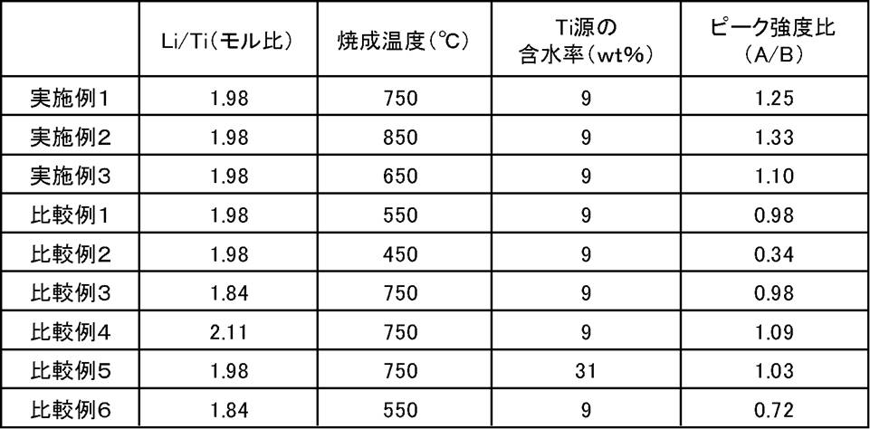
- Table 1 the peak intensity ratio A / B of the composition for an electricity storage device of Example 1 was 1.25, and the peak intensity ratio A / B of the composition for an electricity storage device of Example 2 was 1 .33, the peak intensity ratio A / B of the composition for electricity storage device of Example 3 is 1.10, and the peak intensity ratio A / B of the composition for electricity storage device of Comparative Example 1 is 0.98.
- the peak intensity ratio A / B of the power storage device composition of Comparative Example 2 is 0.34, and the peak strength ratio A / B of the power storage device composition of Comparative Example 3 is 0.98.
- the peak intensity ratio A / B of the power storage device composition was 1.09, the peak strength ratio A / B of the power storage device composition of Comparative Example 5 was 1.03, and the power storage device composition of Comparative Example 6 was used.
- the peak intensity ratio A / B of the composition was 0.72.
- Li / Ti (molar ratio), firing temperature (° C.), moisture content of Ti source (wt%), peak intensity ratio (A) of each of the power storage device compositions of Examples 1 to 3 and Comparative Examples 1 to 6 / B) is shown in Table 1.
- the electrical storage device using the separator is produced, and the blue-inhibition effect (measurement of lightness (L value)), gas The generation suppression effect and battery characteristics (leakage current) were evaluated.
- each power storage device composition of Examples 1 to 3 and Comparative Examples 1 to 6 and 4.5 g of polyvinylidene fluoride were kneaded, and then N-methyl-2-pyrrolidone (manufactured by Kishida Chemical Co., Ltd.) 16.
- Each separator coating material was prepared by diluting with 9 g.
- each separator for electricity storage device was produced by applying each separator paint produced using a wire bar to a separator (manufactured by Nippon Advanced Paper Industries Co., Ltd.).
- the coating material for separators was in the state exposed to the negative electrode side a little.
- the coat-weight was prepared as 10g / m 2, 20g / m 2, 40g / m 2, 4 kinds of 70 g / m 2 of (levels).
- volume change rate (%) volume change (ml) ⁇ initial volume (ml) ⁇ 100
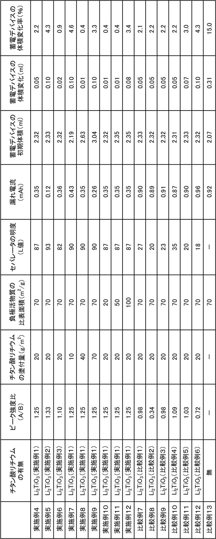
- the electricity storage devices of Examples 4 to 12 were more effective than the electricity storage device of Comparative Example 13 using only the separator (the electricity storage device separator not using the separator coating material).
- the generation amount absolute amount
- the volume change rate was small (more specifically, the volume change rate was 5% or less).
- the composition for an electricity storage device by using lithium titanate (Li 2 TiO 3 ) having a specific peak ratio as a main component, a reducing atmosphere as compared with conventional lithium compounds. It has been found that the electrical conductivity due to blue discoloration (reduction) can be suppressed even when used in the above. In addition, leakage current can be reduced while suppressing the development of conductivity due to blue discoloration (reduction), and in addition, carbon dioxide gas and hydrogen gas during use and changes with time, which has been a problem in conventional power storage devices It was found that generation of various gases such as fluorine gas can be suppressed.
- composition for an electricity storage device of the present invention can be used for an electricity storage device such as a lithium ion battery or an electric double layer capacitor.
Landscapes
- Chemical & Material Sciences (AREA)
- Engineering & Computer Science (AREA)
- Power Engineering (AREA)
- General Chemical & Material Sciences (AREA)
- Electrochemistry (AREA)
- Chemical Kinetics & Catalysis (AREA)
- Organic Chemistry (AREA)
- Inorganic Chemistry (AREA)
- Microelectronics & Electronic Packaging (AREA)
- Environmental & Geological Engineering (AREA)
- Manufacturing & Machinery (AREA)
- Life Sciences & Earth Sciences (AREA)
- Geology (AREA)
- General Life Sciences & Earth Sciences (AREA)
- Materials Engineering (AREA)
- Inorganic Compounds Of Heavy Metals (AREA)
- Electric Double-Layer Capacitors Or The Like (AREA)
- Cell Separators (AREA)
- Secondary Cells (AREA)
Abstract
Description
また、特定のピーク比を持つチタン酸リチウム(Li2TiO3)を主成分とすることによって、電池特性を低下させることなく、従前の蓄電デバイスにおいて問題となっていた使用時や経時変化における炭酸ガス、水素ガス、フッ素ガスなどの各種のガスの発生を抑制することができる蓄電デバイス用セパレータおよび蓄電デバイスに関するものである。
しかしながら、このような蓄電デバイスにおいては、蓄電デバイスの内に存在する不純物(例えば活物質内に残存している未反応の炭酸リチウムなど)や水分の混入、あるいは使用によって電解液や電極を構成する材料が酸化分解することなどが原因となって、蓄電デバイス内に炭酸ガス、水素ガス、フッ素ガスなどのガスが発生してしまうという課題がある。係るガスは蓄電デバイスの電池特性を低下させる原因となるものであり、また、このようなガスの発生が継続することになると蓄電デバイスからの液漏れや形状変化(膨張)を招き、最終的には炎上、爆発という重大事象を引き起こすことになるものとなる。
ここで、このようなガスの中には、未反応の炭酸リチウムが経時劣化(分解)したり、充放電を繰り返すことによって電解液が酸化分解したりすることによって発生するガス(炭酸ガス)といったものもあるが、このようなガスとは別に、水素ガス、フッ素ガスの原因となるプロトン(H+)も発生する。具体的には、蓄電デバイス内に浸入した水分自体が電気分解することによって発生するプロトン(H+)や、電解液に電解質としてヘキサフルオロリン酸リチウム(LiPF6)やホウフッ化リチウム(LiBF4)などを用いている場合に、係る電解質から分解したBF4 -やPF6 -などの陰イオンと蓄電デバイス内に浸入した水分とが反応して形成されたフッ化水素(HF)がさらに解離することによって発生するプロトン(H+)などがある。そして、係るプロトン同士が結合することで水素ガスが発生したり、フッ化水素(HF)から解離したフッ素イオン同士が結合することでフッ素ガスが発生したりするのである。
また、電解質から分解したBF4 -やPF6 -などの陰イオンと未反応の炭酸リチウムとが反応することによって発生する炭酸ガスもある。
従って、これらの文献に記載されている各種の吸収材は、液漏れ、形状変化(膨張)、炎上、爆発という事象については防止することができるかもしれないが、ガスが発生している(電解液や電極を構成する材料の酸化分解などが発生している)ことには変わりがないことから、電池特性の低下を防止することはできないものとなっている。
従って、従前においてリチウム化合物を用いる際には正極の材料として用いることが一般的となっている。また、リチウム化合物をセパレータの材料として用いる際には正極側に配置、塗布するような形態(負極側に露出しないような形態)で用いることになるが、このような形態とするためには製造工程が煩雑になってしまうという課題がある。
また、青変(還元)による導電性の発現を抑制しつつ、従前の蓄電デバイスにおいて問題となっていた使用時や経時変化における炭酸ガス、水素ガス、フッ素ガスなどの各種のガスの発生も抑制すること、具体的にはガス発生の源となるプロトン(H+)自体を捕捉することができるという知見を得るに至った。
具体的には、以下に示す反応式のように、本発明の蓄電デバイス用組成物のリチウムイオンと、蓄電デバイス内において発生するプロトンとがイオン交換反応をすることによって、ガス発生の源となるプロトン(H+)自体を捕捉することができるのである。
また、本発明の蓄電デバイス用ガス組成物のチタン酸イオンと炭酸イオンとがイオン交換反応をすることによって、炭酸ガスも捕捉することができるのである。
Li2TiO3 + 2H+ → H2TiO3 + 2Li+(プロトン捕捉=イオン交換反応)
Li2TiO3 + CO2 → Li2CO3 + TiO2(CO2吸収)
本発明の蓄電デバイス用組成物は、チタン酸リチウムの中でも213型のチタン酸リチウム(Li2TiO3)を主成分とするものであり、さらにX線回折パターンにおける2θ(回折角)=18.4±0.1°のピーク強度(A)と2θ(回折角)=43.7±0.1°のピーク強度(B)の強度比(A/B)が1.10以上であるLi2TiO3を主成分とするものである。このように、本発明の蓄電デバイス用組成物は、特定のピーク比を持つLi2TiO3を主成分とすることによって、従前のリチウム化合物に比べて還元雰囲気における使用においても青変(還元)による導電性の発現を抑制することができるのである。
従って、本発明における「主成分とする」とは、上記のように各種の構造のチタン酸リチウムが含まれてしまう場合であってもLi2TiO3の組成を持つチタン酸リチウムを主成分とするとの意である。具体的には、Li2TiO3の組成を持つチタン酸リチウムの含有率が70%以上のものをいう。さらに、90%以上がより好ましく、95%以上が最も好ましい。
さらに、本発明の蓄電デバイス用組成物は、Li2TiO3の結晶構造中の002面の特徴的なピークである2θ(回折角)=18.4±0.1°のピーク強度をAとし、Li2TiO3の結晶構造中の113面の特徴的なピークである2θ(回折角)=43.7±0.1°のピーク強度をBとした場合の強度比(A/B)が1.10以上であるLi2TiO3を主成分とするものである。つまり、本発明の蓄電デバイス用組成物は、002面方向に成長したLi2TiO3という特徴を持つことによって、従前のリチウム化合物に比べて還元雰囲気における使用においても青変(還元)による導電性の発現を抑制することができるものとなり得るのである。
なお、ピーク強度比(A/B)が1.10以上であれば上限については特に限定されるものではないが、あまり高くなりすぎても青変(還元)の抑制効果が頭打ちとなることから、ピーク強度比(A/B)の上限値を1.50とすることが好ましい。そしてその中でもピーク強度比(A/B)を1.10~1.33とすることが好ましい。
本発明の蓄電デバイス用組成物の原料となるLi源については、特に限定されるものではなく炭酸リチウム、水酸化リチウム、硝酸リチウムなど各種のLi源を用いることができる。そして、その中でも本発明の特定のピーク強度を持つ蓄電デバイス用組成物を作製し易いことから水酸化リチウムを用いることが好ましい。
本発明の蓄電デバイス用組成物の原料となるTi源についてもLi源と同様に特に限定されるものではなく、メタチタン酸などの各種のチタン酸化合物、アナタース型またはルチル型の酸化チタン、塩化チタン、硫酸チタン、硫酸チタニルなど各種のTi源を用いることができる。そして、その中でも本発明の特定のピーク強度を持つ蓄電デバイス用組成物を作製し易いことからアナタース型の酸化チタンを用いることが好ましい。
また、Ti源として酸化チタンを用いる場合には、その結晶構造中の含水率が25wt%未満であることが好ましく、15wt%未満であることがさらに好ましく、10wt%未満であることが最も好ましい。一方、結晶構造中の含水率が25wt%以上の酸化チタンを用いた場合には、本発明の特定のピーク強度を持つ蓄電デバイス用組成物を作製し難いことから好ましくない。ここで、結晶構造中の含水率は、熱重量分析(TG)において100℃から400℃の温度範囲での重量減少率を意味する。
また、本発明の蓄電デバイス用組成物は、特定のピーク比とすることによって還元による導電性の発現を抑制することができるものとなることから、特徴的な色相を示すものとなる。
ここで、チタン酸リチウムは通常、還元されると青色に変色することが知られていることから、本発明の蓄電デバイス用組成物は充電の前後においても青変が抑制され、具体的には明度(L値)が80以上を示すものとなる。また、その中でも明度(L値)が82~93を示すものが好ましいこととなる。
なお、本発明の蓄電デバイス用組成物の製造方法としては公知の方法を用いることができるが、高い含有率で特定のピーク比を持つチタン酸リチウム(Li2TiO3)を得ることができる点から、大気中において650℃以上の温度で2hrの1回焼成を行うことによって製造することが好ましい。そして、その中でも、大気中において750~850℃の温度で2hrの1回焼成を行うことによって製造することがより好ましい。
また、前記Li2TiO3の組成を持つチタン酸リチウムの含有率を95%以上にするためには、厳密なLi/Ti(モル比)の管理が必須であり、Li/Ti(モル比)を1.85以上2.10以下とすることが好ましい。さらに好ましくは、1.90以上2.05以下であり、最も好ましくは1.95以上2.00以下である。
本発明に係る蓄電デバイス用組成物は、リチウムイオン電池や電気二重層キャパシタなどの蓄電デバイスの材料、具体的には正極やセパレータの材料として用いることができる。そしてその中でも、セパレータの材料として用いる場合には従前のように正極側に配置、塗布するような形態とする必要がなく、煩雑な製造工程を採用する必要がなくなることというメリットを有することになる。
まず、含水率9wt%に調整したアナタース型酸化チタン(テイカ社製AMT-100)300gと水酸化リチウム266gを湿式混合した。このときのLi/Ti(モル比)は1.98であった。次に、大気中において750℃で2hr焼成することによって、213型のチタン酸リチウム(Li2TiO3)を主成分とする実施例1の蓄電デバイス用組成物を作製した。
焼成温度を850℃とする以外は実施例1と同様にして、213型のチタン酸リチウム(Li2TiO3)を主成分とする実施例2の蓄電デバイス用組成物を作製した。
焼成温度を650℃とする以外は実施例1と同様にして、213型のチタン酸リチウム(Li2TiO3)を主成分とする実施例3の蓄電デバイス用組成物を作製した。
焼成温度を550℃とする以外は実施例1と同様にして、213型のチタン酸リチウム(Li2TiO3)を主成分とする比較例1の蓄電デバイス用組成物を作製した。
焼成温度を450℃とする以外は実施例1と同様にして、213型のチタン酸リチウム(Li2TiO3)を主成分とする比較例2の蓄電デバイス用組成物を作製した。
Li/Ti(モル比)を1.84とする以外は実施例1と同様にして、213型のチタン酸リチウム(Li2TiO3)を主成分とする比較例3の蓄電デバイス用組成物を作製した。
Li/Ti(モル比)を2.11とする以外は実施例1と同様にして、比較例4の蓄電デバイス用組成物を作製した。
Ti源として、含水率31wt%に調整したアナタース型酸化チタン(テイカ社製)396gを用いる以外は実施例1と同様にして、比較例5の蓄電デバイス用組成物を作製した。
焼成温度を550℃とする以外は比較例3と同様にして、比較例6の蓄電デバイス用組成物を作製した。
次に、作製した実施例1~3および比較例1~6の各蓄電デバイス用組成物についてX線回折装置(パナリティカル社製X‘Pert)による測定を行った。結果を図1~図9に示す。
まず、実施例1~3および比較例1~6の各蓄電デバイス用組成物8.6gとポリフッ化ビニリデン4.5gを混練したのち、N-メチル-2-ピロリドン(キシダ化学社製)16.9gを用いて希釈することによって、各セパレータ用塗料を作製した。
次に、ワイヤーバーを用いて作製した各セパレータ用塗料をセパレータ(日本高度紙工業社製)に塗付することによって、各蓄電デバイス用セパレータを作製した。なお、塗布後の各蓄電デバイス用セパレータについては、後記する蓄電デバイスを作製する際に負極側となる面にもセパレータ用塗料が若干露出している状態であった。また、塗付量については10g/m2、20g/m2、40g/m2、70g/m2の4種類(水準)のものを作製した。
まず、オルソチタン酸(テイカ社製)520gと水酸化リチウム・1水和物(FMC社製)218gを湿式混合したのち、大気中750℃、700℃、650℃、550℃で2hr焼成することによって、それぞれ、比表面積20m2/g、50m2/g、70m2/g、100m2/gの微粒子Li4Ti5O12を得た。
次に、上記にて作製した各蓄電デバイス用セパレータと、正極活物質として活性炭(ATエレクトロード社製AP20-0001)を用いた正極、負極活物質として前記の比表面積20m2/g、50m2/g、70m2/g、100m2/gのLi4Ti5O12を用いた4種類(水準)の負極を準備した。
そして、各蓄電デバイス用セパレータと負極活物質を表2に記載の組合せとし、図10のように配置(積層)した後、ケースに納め、さらに電解液として1MのLiBF4/EC:DEC=1:2(キシダ化学社製)を注液した後、封止することによって、実施例4~12および比較例7~12の各蓄電デバイスを作製した。なお、このときの電気容量は600μAhであった。
また、比較例として、比較例7~12の各蓄電デバイスに加えて、日本高度紙工業社製のセパレータのみ(上記セパレータ用塗料を用いない蓄電デバイス用セパレータ)を用いた比較例13の蓄電デバイスについても作製した。
作製した実施例4~12および比較例7~13の各蓄電デバイスを25℃の条件下において2.9Vまで充電した。そして、充電後の蓄電デバイスを解体してセパレータを取り出した後、色差計(日本電色工業株式会社製ZE6000)を用いてセパレータの明度(L値)を測定した。
作製した実施例4~12および比較例7~13の各蓄電デバイスを60℃の条件下において2.9Vまで充電した後、2.9Vの定電圧を維持した。そして、定電圧を維持して30分後の電流値を漏れ電流として測定した。
まず、作製した実施例4~12および比較例7~13の各蓄電デバイスの初期体積を、アルキメデスの原理に基づいて測定した。具体的には、25℃の水を張った水槽に蓄電デバイスを沈め、そのときの重量変化から各蓄電デバイスの初期体積を算出した。
次に、各蓄電デバイスを60℃の条件下において1.5~2.9Vの電圧範囲、0.5Cの充放電速度の条件の下で3サイクル充放電を行った。その後、上記測定方法と同様にして、充放電後の各蓄電デバイスの体積を算出し、初期体積との差から充放電前後の各蓄電デバイスの体積変化を求めることによって、各蓄電デバイスからのガス発生量を測定した。また、以下の計算式から、各蓄電デバイスの体積変化率も求めた。
体積変化率(%)=体積変化(ml)÷初期体積(ml)×100
一方、比較例7~12の蓄電デバイスは、ピーク強度比A/Bが1.10未満のチタン酸リチウム(Li2TiO3)をセパレータに塗布していることから、セパレータの明度(L値)が18~35という低い値となり、チタン酸リチウム(Li2TiO3)が青変(還元)されるという結果となった。
一方、比較例7~12の蓄電デバイスは、チタン酸リチウム(Li2TiO3)が青変(還元)されることから、電流値が0.87~0.96mAhという高い値となり、セパレータのみ(上記セパレータ用塗料を用いない蓄電デバイス用セパレータ)を用いた比較例13の蓄電デバイスの電流値(0.92mAh)とほとんど変わらないと結果となった。
2 正極
3 セパレータ(蓄電デバイス用組成物を含有)
4 負極
5 タブリード
6 ケース
Claims (3)
- X線回折パターンにおける2θ(回折角)=18.4±0.1°のピーク強度(A)と2θ(回折角)=43.7±0.1°のピーク強度(B)の強度比(A/B)が、
1.10以上であるLi2TiO3を主成分とすることを特徴とする蓄電デバイス用組成物。
- 請求項1に記載の蓄電デバイス用組成物を用いることを特徴とする蓄電デバイス用セパレータ。
- 請求項2に記載の蓄電デバイス用セパレータを用いることを特徴とする蓄電デバイス。
Priority Applications (4)
| Application Number | Priority Date | Filing Date | Title |
|---|---|---|---|
| KR1020197032134A KR102528382B1 (ko) | 2017-05-01 | 2018-04-27 | 축전 디바이스용 조성물 및 이 축전 디바이스용 조성물을 사용한 축전 디바이스용 세퍼레이터 및 축전 디바이스 |
| JP2019515720A JP7007375B2 (ja) | 2017-05-01 | 2018-04-27 | 蓄電デバイス用組成物およびこの蓄電デバイス用組成物を用いた蓄電デバイス用セパレータおよび蓄電デバイス |
| CN201880028841.XA CN110622336B (zh) | 2017-05-01 | 2018-04-27 | 蓄电装置用钛酸锂组合物、蓄电装置用隔板和蓄电装置 |
| US16/610,035 US11302993B2 (en) | 2017-05-01 | 2018-04-27 | Power storage device composition, power storage device separator using power storage device composition, and power storage device |
Applications Claiming Priority (4)
| Application Number | Priority Date | Filing Date | Title |
|---|---|---|---|
| JP2017091480 | 2017-05-01 | ||
| JP2017-091480 | 2017-05-01 | ||
| JP2017-135139 | 2017-07-11 | ||
| JP2017135139 | 2017-07-11 |
Publications (1)
| Publication Number | Publication Date |
|---|---|
| WO2018203522A1 true WO2018203522A1 (ja) | 2018-11-08 |
Family
ID=64016107
Family Applications (1)
| Application Number | Title | Priority Date | Filing Date |
|---|---|---|---|
| PCT/JP2018/017185 Ceased WO2018203522A1 (ja) | 2017-05-01 | 2018-04-27 | 蓄電デバイス用組成物およびこの蓄電デバイス用組成物を用いた蓄電デバイス用セパレータおよび蓄電デバイス |
Country Status (5)
| Country | Link |
|---|---|
| US (1) | US11302993B2 (ja) |
| JP (1) | JP7007375B2 (ja) |
| KR (1) | KR102528382B1 (ja) |
| CN (1) | CN110622336B (ja) |
| WO (1) | WO2018203522A1 (ja) |
Citations (7)
| Publication number | Priority date | Publication date | Assignee | Title |
|---|---|---|---|---|
| JPH01203039A (ja) * | 1988-02-08 | 1989-08-15 | Agency Of Ind Science & Technol | 新規なリチウム選択性を示す吸着剤及びその製造方法 |
| JP2011521881A (ja) * | 2008-06-03 | 2011-07-28 | ジュート−ヒェミー アクチェンゲゼルシャフト | チタン酸リチウムスピネルの製造方法および使用方法 |
| WO2016159359A1 (ja) * | 2015-04-03 | 2016-10-06 | 日本ケミコン株式会社 | ハイブリッドキャパシタ及びハイブリッドキャパシタ用セパレータ |
| JP2016197647A (ja) * | 2015-04-03 | 2016-11-24 | 日本ケミコン株式会社 | ハイブリッドキャパシタ用セパレータおよびハイブリッドキャパシタ |
| JP2016197649A (ja) * | 2015-04-03 | 2016-11-24 | 日本ケミコン株式会社 | 電気二重層キャパシタ用セパレータおよび電気二重層キャパシタ |
| JP2016197648A (ja) * | 2015-04-03 | 2016-11-24 | 日本ケミコン株式会社 | 電気二重層キャパシタ |
| JP2017177064A (ja) * | 2016-03-31 | 2017-10-05 | 国立大学法人信州大学 | チタン酸系リチウム吸着剤およびその製造方法 |
Family Cites Families (12)
| Publication number | Priority date | Publication date | Assignee | Title |
|---|---|---|---|---|
| JPS5231016B2 (ja) | 1972-12-28 | 1977-08-12 | ||
| JP2003197487A (ja) | 2001-12-28 | 2003-07-11 | Nec Tokin Corp | 電気二重層キャパシタ |
| JP2003297699A (ja) | 2002-03-29 | 2003-10-17 | Nec Tokin Corp | 電気二重層キャパシタ |
| JP4249727B2 (ja) * | 2005-05-13 | 2009-04-08 | 株式会社東芝 | 非水電解質電池およびリチウムチタン複合酸化物 |
| EP1932588B1 (en) | 2005-09-16 | 2013-08-07 | Chuo University | Method for producing carbon dioxide absorbing material |
| JP5095179B2 (ja) * | 2006-11-10 | 2012-12-12 | 株式会社東芝 | 非水電解質電池、リチウムチタン複合酸化物および電池パック |
| JP5485741B2 (ja) | 2010-02-12 | 2014-05-07 | 株式会社巴川製紙所 | 電子部品用セパレータの製造方法 |
| CA2809511A1 (en) * | 2010-08-31 | 2012-03-08 | Toda Kogyo Corporation | Lithium titanate particles and process for producing the lithium titanate particles, mg-containing lithium titanate particles and process for producing the mg-containing lithium titanate particles, negative electrode active substance particles for non-aqueous electrolyte secondary batteries, and non-aqueous electrolyte secondary battery |
| CN102306798B (zh) * | 2011-09-30 | 2014-06-18 | 南开大学 | 一种用于锂离子二次电池负极材料及其制备方法 |
| JP2013095646A (ja) * | 2011-11-02 | 2013-05-20 | Taiyo Yuden Co Ltd | リチウムチタン複合酸化物、それを用いた電池用電極およびリチウムイオン二次電池 |
| CN102746000A (zh) * | 2012-07-11 | 2012-10-24 | 中南大学 | 一种水热法制备钛酸锂陶瓷粉体的方法 |
| JP2017063043A (ja) * | 2016-11-08 | 2017-03-30 | 宇部興産株式会社 | 蓄電デバイスの電極用チタン酸リチウム粉末および活物質材料、並びにそれを用いた電極シートおよび蓄電デバイス |
-
2018
- 2018-04-27 JP JP2019515720A patent/JP7007375B2/ja active Active
- 2018-04-27 KR KR1020197032134A patent/KR102528382B1/ko active Active
- 2018-04-27 WO PCT/JP2018/017185 patent/WO2018203522A1/ja not_active Ceased
- 2018-04-27 US US16/610,035 patent/US11302993B2/en active Active
- 2018-04-27 CN CN201880028841.XA patent/CN110622336B/zh active Active
Patent Citations (7)
| Publication number | Priority date | Publication date | Assignee | Title |
|---|---|---|---|---|
| JPH01203039A (ja) * | 1988-02-08 | 1989-08-15 | Agency Of Ind Science & Technol | 新規なリチウム選択性を示す吸着剤及びその製造方法 |
| JP2011521881A (ja) * | 2008-06-03 | 2011-07-28 | ジュート−ヒェミー アクチェンゲゼルシャフト | チタン酸リチウムスピネルの製造方法および使用方法 |
| WO2016159359A1 (ja) * | 2015-04-03 | 2016-10-06 | 日本ケミコン株式会社 | ハイブリッドキャパシタ及びハイブリッドキャパシタ用セパレータ |
| JP2016197647A (ja) * | 2015-04-03 | 2016-11-24 | 日本ケミコン株式会社 | ハイブリッドキャパシタ用セパレータおよびハイブリッドキャパシタ |
| JP2016197649A (ja) * | 2015-04-03 | 2016-11-24 | 日本ケミコン株式会社 | 電気二重層キャパシタ用セパレータおよび電気二重層キャパシタ |
| JP2016197648A (ja) * | 2015-04-03 | 2016-11-24 | 日本ケミコン株式会社 | 電気二重層キャパシタ |
| JP2017177064A (ja) * | 2016-03-31 | 2017-10-05 | 国立大学法人信州大学 | チタン酸系リチウム吸着剤およびその製造方法 |
Also Published As
| Publication number | Publication date |
|---|---|
| KR102528382B1 (ko) | 2023-05-02 |
| KR20190139912A (ko) | 2019-12-18 |
| CN110622336A (zh) | 2019-12-27 |
| US11302993B2 (en) | 2022-04-12 |
| CN110622336B (zh) | 2022-07-26 |
| US20200203691A1 (en) | 2020-06-25 |
| JPWO2018203522A1 (ja) | 2020-05-14 |
| JP7007375B2 (ja) | 2022-01-24 |
Similar Documents
| Publication | Publication Date | Title |
|---|---|---|
| CN104411640B (zh) | 掺杂的尖晶石及其制备方法和用途、以及锂离子电池组 | |
| JP5218406B2 (ja) | 水系リチウム二次電池 | |
| EP2826749A1 (en) | Lithium titanate and production method and use for same | |
| JP6639953B2 (ja) | ナトリウムイオン二次電池用電極活物質およびその製造方法、並びにナトリウムイオン二次電池 | |
| EP2669253A1 (en) | Titanium oxide for electrode and method for manufacturing the same | |
| JP5810752B2 (ja) | チタン酸リチウム粒子粉末、非水電解質二次電池用負極活物質粒子粉末並びに非水電解質二次電池 | |
| JP7007375B2 (ja) | 蓄電デバイス用組成物およびこの蓄電デバイス用組成物を用いた蓄電デバイス用セパレータおよび蓄電デバイス | |
| JP2017004805A (ja) | 電池の負極材料 | |
| JP5894337B2 (ja) | 酸化チタン化合物並びにこれを用いた電極及びリチウムイオン二次電池 | |
| JP2007220406A (ja) | 非水電解液電池 | |
| JP6636827B2 (ja) | ナトリウムイオン二次電池用電極活物質およびその製造方法、並びにナトリウムイオン二次電池 | |
| JP7187123B2 (ja) | 蓄電デバイス用ガス発生抑制剤およびこの蓄電デバイス用ガス発生抑制剤を用いた蓄電デバイス用正極および蓄電デバイス | |
| JP4055414B2 (ja) | リチウムイオン二次電池用正極活物質 | |
| JP2023137856A (ja) | FeOHSO4粒子の製造方法、リチウムイオン二次電池用の正極活物質、及びリチウムイオン二次電池 | |
| JP6257222B2 (ja) | ラムスデライト型チタン酸リチウムおよびこのラムスデライト型チタン酸リチウムを用いたリチウムイオン二次電池並びにリチウムイオンキャパシタ | |
| JP6455787B2 (ja) | チタン酸化物およびその製造方法、二次電池用活物質およびその製造方法、並びにチタン酸化物を活物質として用いた二次電池 | |
| JP7121730B2 (ja) | 蓄電デバイス用ガス発生抑制剤およびこの蓄電デバイス用ガス発生抑制剤を用いた蓄電デバイス | |
| JP7250324B2 (ja) | 電極材料及びそれを用いた電極、電池 | |
| WO2019058822A1 (ja) | チタン酸化物及びその製造方法、並びに該チタン酸化物を用いた電極活物質及び蓄電デバイス | |
| WO2013129423A1 (ja) | チタン酸リチウム粒子粉末、非水電解質二次電池用負極活物質粒子粉末並びに非水電解質二次電池 | |
| WO2025028348A1 (ja) | リチウム一次電池 | |
| WO2022264992A1 (ja) | リチウム二次電池用正極活物質、リチウム二次電池用正極、リチウム二次電池及びリチウム二次電池用正極活物質の製造方法 |
Legal Events
| Date | Code | Title | Description |
|---|---|---|---|
| 121 | Ep: the epo has been informed by wipo that ep was designated in this application |
Ref document number: 18794237 Country of ref document: EP Kind code of ref document: A1 |
|
| ENP | Entry into the national phase |
Ref document number: 2019515720 Country of ref document: JP Kind code of ref document: A |
|
| ENP | Entry into the national phase |
Ref document number: 20197032134 Country of ref document: KR Kind code of ref document: A |
|
| NENP | Non-entry into the national phase |
Ref country code: DE |
|
| 122 | Ep: pct application non-entry in european phase |
Ref document number: 18794237 Country of ref document: EP Kind code of ref document: A1 |