WO2018199082A1 - 浴室ユニット - Google Patents
浴室ユニット Download PDFInfo
- Publication number
- WO2018199082A1 WO2018199082A1 PCT/JP2018/016586 JP2018016586W WO2018199082A1 WO 2018199082 A1 WO2018199082 A1 WO 2018199082A1 JP 2018016586 W JP2018016586 W JP 2018016586W WO 2018199082 A1 WO2018199082 A1 WO 2018199082A1
- Authority
- WO
- WIPO (PCT)
- Prior art keywords
- frame
- door
- bathtub
- bathroom unit
- vertical frame
- Prior art date
- Legal status (The legal status is an assumption and is not a legal conclusion. Google has not performed a legal analysis and makes no representation as to the accuracy of the status listed.)
- Ceased
Links
Images







Classifications
-
- A—HUMAN NECESSITIES
- A47—FURNITURE; DOMESTIC ARTICLES OR APPLIANCES; COFFEE MILLS; SPICE MILLS; SUCTION CLEANERS IN GENERAL
- A47K—SANITARY EQUIPMENT; ACCESSORIES THEREFOR, e.g. TOILET ACCESSORIES
- A47K3/00—Baths; Showers; Appurtenances therefor
- A47K3/02—Baths
-
- A—HUMAN NECESSITIES
- A47—FURNITURE; DOMESTIC ARTICLES OR APPLIANCES; COFFEE MILLS; SPICE MILLS; SUCTION CLEANERS IN GENERAL
- A47K—SANITARY EQUIPMENT; ACCESSORIES THEREFOR, e.g. TOILET ACCESSORIES
- A47K4/00—Combinations of baths, showers, sinks, wash-basins, closets, or urinals, not covered by a single other group of this subclass
-
- E—FIXED CONSTRUCTIONS
- E04—BUILDING
- E04H—BUILDINGS OR LIKE STRUCTURES FOR PARTICULAR PURPOSES; SWIMMING OR SPLASH BATHS OR POOLS; MASTS; FENCING; TENTS OR CANOPIES, IN GENERAL
- E04H1/00—Buildings or groups of buildings for dwelling or office purposes; General layout, e.g. modular co-ordination or staggered storeys
- E04H1/12—Small buildings or other erections for limited occupation, erected in the open air or arranged in buildings, e.g. kiosks, waiting shelters for bus stops or for filling stations, roofs for railway platforms, watchmen's huts or dressing cubicles
-
- E—FIXED CONSTRUCTIONS
- E06—DOORS, WINDOWS, SHUTTERS, OR ROLLER BLINDS IN GENERAL; LADDERS
- E06B—FIXED OR MOVABLE CLOSURES FOR OPENINGS IN BUILDINGS, VEHICLES, FENCES OR LIKE ENCLOSURES IN GENERAL, e.g. DOORS, WINDOWS, BLINDS, GATES
- E06B3/00—Window sashes, door leaves, or like elements for closing wall or like openings; Layout of fixed or moving closures, e.g. windows in wall or like openings; Features of rigidly-mounted outer frames relating to the mounting of wing frames
Definitions
- the present invention relates to a bathroom unit.
- a compact bathroom unit that includes a waterproof pan that receives hot water discharged from a shower device and a wall portion that is disposed so as to surround the waterproof pan.
- Patent Document 1 has a deep waterproof pan that can store hot water at a depth that allows bathing, and a shower device is provided on a wall portion or a ceiling portion that is disposed at the peripheral edge of the waterproof pan.
- a bathroom unit is disclosed.
- the waterproof pan has a hot water supply means for dropping hot water therein, and functions as a bathtub for storing hot water.
- the waterproof pan is provided with a drain plug and an overflow drain port.
- the bathroom unit is provided with an entrance on the front side so that the door can be opened and closed.
- Patent Document 2 discloses a bathroom unit in which the bathroom and the toilet room are separate rooms.
- the bathroom unit includes a bathtub provided on one side of the floor, a toilet provided on the other side of the floor, and a sash disposed between the bathtub and the toilet.
- the bathroom unit is partitioned into a bathroom and a toilet room by a sash.
- the first invention is made in view of such circumstances, and an object of the first invention is to provide a bathroom unit in which a bathtub is surrounded by a wall body and a door and can be easily moved into and out of the bathroom. It is in.
- the second invention has been made in view of such circumstances, and its object is to provide a bathroom unit in which a bathtub is surrounded by a wall body and a door, and an outer wall plate can be easily constructed. is there.
- the bathroom In the bathroom unit described in Patent Document 2, the bathroom is partitioned by a sash, but no means for preventing the outflow of hot water used in the bathroom to the toilet room side is seen, and the hot water goes to the toilet room side. There was a probability of spilling. When the hot water used in the bathroom flows out to the toilet room, the bathroom unit takes time and effort to wipe off the water accumulated on the toilet room.
- the third invention has been made in view of such circumstances, and the object of the invention is a bathroom unit in which a bathtub is surrounded by a wall and a door, and the outflow of hot water from the door can be prevented. Is to provide.
- a certain aspect of the first invention is a bathroom unit.
- the bathroom unit includes a bathtub for storing hot water, a trap section disposed below the bathtub, a wall body and a door disposed on a peripheral edge of the bathtub so as to surround the bathtub, and the door.
- the frame portion has a lower frame disposed on the peripheral edge, and a depth from the peripheral edge to the bottom of the bathtub is 350 mm or less, and a floor to be installed The height from the top to the upper end of the lower frame is 500 mm or less.
- the bathroom unit which concerns on another aspect of 1st invention is the wall arrange
- a bathroom unit comprising a body and a door, and a frame part into which the door is fitted, the frame part has a lower frame disposed on the peripheral edge part and a facing surface part facing the bottom part of the door is formed. It is characterized by.
- a certain aspect of the second invention is a bathroom unit.
- the bathroom unit includes a bathtub for storing hot water, a wall body and a door disposed on a peripheral edge of the bathtub so as to surround the bathtub, and a frame for fitting the door.
- the part has a left vertical frame and a right vertical frame extending from the lower side to the upper side of the peripheral part.
- a certain aspect of the third invention is a bathroom unit.
- the bathroom unit includes a bathtub for storing hot water, a wall body and a door disposed on a peripheral edge of the bathtub so as to surround the bathtub, and a frame for fitting the door.
- the portion has a lower frame disposed on the peripheral edge portion, and a first seal member for sealing a gap between the bottom portion of the door and the lower frame is provided.
- the bathtub in the bathroom unit, the bathtub is surrounded by the wall and the door, so that the bathroom unit can be easily moved into and out of the bathroom.
- the bathtub in the bathroom unit, the bathtub is surrounded by the wall body and the door, so that the construction of the outer wall plate is facilitated.
- the bathtub in the bathroom unit, the bathtub is surrounded by the wall body and the door, and the outflow of hot water from the door can be prevented.
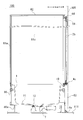
- FIG. 3 is a cross-sectional view of the bathroom unit taken along line AA shown in FIG. 2. It is a longitudinal cross-sectional view in the center part of a door. It is a perspective view which shows the external appearance of a wheel part. It is a graph which shows the trial calculation value of seating nipple height and seating waist base point height. It is a graph which shows the evaluation content regarding the depth of the hot water in a half body bath.
- FIG. 3 is a cross-sectional view of the bathroom unit along line BB shown in FIG. 2.
- FIG. 9A is an enlarged view of the left vertical frame portion in FIG.
- FIG. 8 is an enlarged view of the right vertical frame portion in FIG.
- FIG. 11A is an enlarged view of the left vertical frame portion in FIG. 10
- FIG. 11B is an enlarged view of the right vertical frame portion in FIG.
- FIG. 3 is a cross-sectional view of the bathroom unit taken along line AA shown in FIG. 2. It is sectional drawing equivalent to the cross section by the BB line of FIG. 2 in the bathroom unit which concerns on a modification.
- FIG. 14A is an enlarged view of the left vertical frame portion in FIG. 13, and FIG. 14B is an enlarged view of the right vertical frame portion in FIG. It is sectional drawing equivalent to the cross section by the CC line of FIG.
- FIG. 16A is an enlarged view of the left vertical frame portion in FIG. 15, and FIG. 16B is an enlarged view of the right vertical frame portion in FIG. It is a perspective view in the edge part of a lower frame. It is a perspective view in the Tojiri heel bottom part of a shoji. It is an end elevation in the Tojiri foot bottom part of the inner shoji.
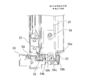
- FIG. 3 is a cross-sectional view of a frame portion taken along line BB shown in FIG. It is a schematic diagram for demonstrating the sealing location by the packing between a door and a frame part.
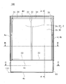
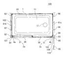
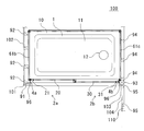
- FIG. 1 is a perspective view showing an appearance of a bathroom unit 100 according to Embodiment 1
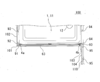
- FIG. 2 is a front view of the bathroom unit 100
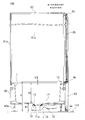
- FIG. 3 is a cross-sectional view of the bathroom unit 100 taken along line AA shown in FIG.
- the bathroom unit 100 includes a bathtub 1, a door 2, a frame portion 4, a wall portion 61, a drainage portion 7, and the like.
- the bathtub 1 has a rectangular shape in plan view, is a deep dish shape that can store hot water, and has a drain port 12 at the bottom 11. Below the bathtub 1, a drainage unit 7 connected to the drainage port 12 is provided.
- the bathtub 1 is surrounded and surrounded by a wall portion 61 and a door 2 disposed on the peripheral edge portion 10, and the upper portion is covered by a ceiling 62.
- the bathtub 1 has a peripheral edge 10 supported on an upper part of a frame 80 that is a rectangular parallelepiped frame structure, and is accommodated inside the frame 80.
- the gantry 80 has leg portions 80a at the lower four corners and the like, and is placed on the indoor floor 111 by the leg portions 80a.
- the bathroom unit 100 is provided with the shower apparatus, the water discharging apparatus, etc. which are arrange
- the wall portion 61 is a wall body 61a disposed on one side along the longitudinal direction of the bathtub 1, and wall bodies 61b and 61c disposed on both sides of the wall body 61a at both ends of the bathtub 1 in the longitudinal direction. It is configured.
- the door 2 is arrange
- the door 2 is a sliding door, and can be opened and closed by sliding both the inner and outer doors 2a and 2b.
- the door 2 is provided between the peripheral edge portion 10 of the bathtub 1 and the ceiling 62, and is fitted in the frame portion 4.
- the inner shoji 2a is configured by inserting a plate 20 made of glass or resin into the inside of a door-toe fence 21, a door-toe fence 22, a lower collar 23, and an upper collar 24 assembled in a rectangular shape.
- the external shoji 2b is configured by fitting a plate 30 made of glass or resin into the inside of a door toe 31, a door butt 32, a lower rod 33 and an upper rod 34 assembled in a rectangular shape. .
- the frame portion 4 includes a left vertical frame 4a, a right vertical frame 4b, a lower frame 4c, an upper frame 4d, and a lower end frame 4e, and is disposed on the other side along the longitudinal direction of the bathtub 1.
- the left vertical frame 4 a and the right vertical frame 4 b are disposed at the corners of the bathtub 1 and extend linearly from below to above the peripheral edge 10 of the bathtub 1.
- the lower ends of the left vertical frame 4a and the right vertical frame 4b are close to the floor 111 so as to be in contact with the floor 111 on which the bathroom unit 100 is placed or to leave a slight gap.
- the left vertical frame 4 a and the right vertical frame 4 b have upper end sides extending substantially to the height position of the ceiling 62.
- the lower frame 4 c is provided between the left vertical frame 4 a and the right vertical frame 4 b so as to follow the peripheral edge portion 10 of the bathtub 1.
- the upper frame 4d is connected to the upper ends of the left vertical frame 4a and the right vertical frame 4b.
- the lower end frame 4e is connected to the lower ends of the left vertical frame 4a and the right vertical frame 4b.
- An apron portion 63 is detachably fitted in an area surrounded by the left vertical frame 4a, the right vertical frame 4b, the lower frame 4c, and the lower end frame 4e, and shields the side portion of the bathtub 1 on the door 2 side. By removing the apron portion 63, the drainage portion 7 behind the bathtub 1 can be inspected and repaired from the side of the bathtub 1.
- the bathroom unit 100 is not provided with a washroom floor on the side of the bathtub 1, and bathing is performed in the bathtub 1.
- the drainage part 7 includes a trap part 71, an overflow pipe 72 and a drainage pipe connection part 73, and is provided between the floor 111 and the bathtub 1.
- the trap unit 71 has a receiving port 71 a connected to the drain port 12 of the bathtub 1, and allows drainage from the bathtub 1 to flow to the drain pipe connection unit 73.
- the trap part 71 keeps the state where water accumulated inside, and seals the drainage path with drainage.
- the overflow pipe 72 has one end connected to the trap part 71 and the other end connected to an overflow plug (not shown) provided in the bathtub 1.
- the drain pipe connection part 73 has one end connected to the trap part 71, the other end connected to a drain pipe, and the drain pipe connected to a drain on the building side.
- the drain pipe connection part 73 flows the waste water from the trap part 71 to the drain outlet on the building side.
- the drainage pipe connecting portion 73 needs to be able to connect a drainage pipe having a larger inner diameter, for example, a drainage pipe having an A50 (outer diameter of about 60 mm) size can be connected. To do.
- the drain pipe connecting portion 73 is provided with a slope that descends from the trap portion 71 side toward the building-side drain port.
- the drainage pipe connecting part 73 has a gradient of, for example, 1/50, and when the pipe connection is made over a distance of 1 m below the bathtub 1, there is a difference in height between the trap part 71 side and the drain side on the building side. 20 mm.
- FIG. 4 is a longitudinal sectional view at the center of the door 2
- FIG. 5 is a perspective view showing the appearance of the wheel portion 35.
- the left-right direction of the paper surface is a prospective direction
- the direction perpendicular to the paper surface is a finding direction.
- the inner shoji 2a has a wheel portion 25 attached to the upper part of the door toe cage 21 and the door butt cage 22.
- the wheel portion 25 includes a main body portion 25a fixed to the upper portions of the door toe rod 21 and the door bottom rod 22, and a wheel 25b that is rotatably supported by the main body portion 25a around an axis in the prospective direction.
- the wheel 25b is placed on a rail portion 51 provided on the upper frame 4d.
- the rail portion 51 has an elongated plate shape, has a width dimension that allows the wheel 25b to be placed in the prospective direction, and extends over the entire length of the upper frame 4d.
- the inner shoji 2a is supported by the rail portion 51, and opens and closes by traveling on the rail portion 51 while the wheel 25b rotates.
- the external shoji 2b has a wheel portion 35 attached to the upper part of the door toe paddle 31 and the door end paddle 32.
- the wheel part 35 has a main body part 35a fixed to the upper part of the door toe fence 31 and the door bottom collar 32, and a wheel 35b supported by the main body part 35a so as to be rotatable around an axis in the prospective direction.
- the wheel 35b is placed on a rail portion 52 provided on the upper frame 4d.
- the rail portion 52 has an elongated plate shape, has a width dimension on which the wheel 35b can be placed in the prospective direction, and extends over the entire length of the upper frame 4d.
- the external shoji 2b is supported by the rail part 51, and opens and closes by traveling on the rail part 51 while the wheel 35b rotates.
- the lower arm 23 of the inner shoji 2a has a guided plate 26 guided by the lower frame 4c.
- the guided plate 26 has an inverted L-shaped cross section perpendicular to the direction of finding, and is elongated along the entire length of the lower collar 23.
- An L-shaped horizontal side of the guided plate 26 is attached to the bottom of the lower rod 23, and the other side of the guide plate 26 is fitted into a guide groove 54c of the lower frame 4c described later.
- the lower arm 33 of the external shoji 2b has a guided plate 36 guided by the lower frame 4c.
- the guided plate 36 has an inverted L-shaped cross section perpendicular to the direction of finding, and is elongated along the entire length of the lower rod 33.
- the guided plate 36 has an L-shaped horizontal side attached to the bottom of the lower rod 33, and the other side arranged vertically is fitted in a guide groove 54d of the lower frame 4c described later.
- the lower frame 4c has a base portion 53 and a guide portion 54 that guides the inner shoji 2a and the outer shoji 2b.
- a frame body 80b extending along the peripheral edge portion is provided below the peripheral edge portion 10 on the door 2 side of the bathtub 1, and an angle member 82 is fixed to the frame body 80b.
- the angle member 82 has an L-shaped cross section in the direction of finding and extends from the left vertical frame 4a to the right vertical frame 4b.
- the base portion 53 is fixed to the angle member 82 and is provided so as to straddle the angle member 82 and the peripheral edge portion 10 of the bathtub 1 on the door 2 side, and extends from the left vertical frame 4a to the right vertical frame 4b. .
- the base 53 has a seat 53a formed on the peripheral edge 10 side of the bathtub 1 in the prospective direction, an outer edge 53b formed on the opposite side of the peripheral edge 10 in the prospective direction, and a grip for gripping the guide part 54. It has a portion 53c.
- the upper surface of the seat 53a is flat and has a gentle slope that descends toward the bathtub 1 side. Due to this gradient, the water that has fallen on the upper surface of the seat 53 a flows down to the peripheral edge 10 of the bathtub 1.
- the outer edge portion 53b is formed one step higher than the seat portion 53a, and dams up so that water does not flow outside.
- the outer edge 53b has a shape in which a corner 53d opposite to the bathtub 1 side has a convex bulge with respect to the upper side.
- the grip portion 53c is formed between the seat portion 53a and the outer edge portion 53b, and forms a recess that opens upward.
- the guide portion 54 includes a leg portion 54a, an opposing surface portion 54b, a guide groove 54c, and a guide groove 54d.
- the leg portion 54a is inserted into the grip portion 53c of the base portion 53 from above and is gripped by the grip portion 53c.
- the guide portion 54 is attached to the base portion 53 by inserting the leg portion 54a into the grip portion 53c, and can be removed by pulling out the leg portion 54a from the grip portion 53c.
- the facing surface portion 54b is formed as the upper surface of the guide portion 54 that faces the bottom of the lower arm 23 of the inner shuffler 2a and the lower armor 33 of the outer obstacle 2b.
- the upper surface of the guide portion 54 formed by the facing surface portion 54b is flat and has a gentle slope that descends toward the bathtub 1 side. Due to this gradient, the water that has fallen on the upper surface of the guide portion 54 flows down to the peripheral edge portion 10 of the bathtub 1.
- the guide groove 54c is provided from the left vertical frame 4a to the right vertical frame 4b so as to pierce the opposing surface portion 54b at a position corresponding to the guided plate 26 provided on the lower arm 23 of the inner impediment 2a.
- the guide groove 54d is provided from the left vertical frame 4a to the right vertical frame 4b so as to pierce the facing surface portion 54b at a position corresponding to the guided plate 36 provided on the lower arm 33 of the external obstacle 2b. Drain holes (not shown) are provided in the side surfaces of the guide grooves 54c and 54d.
- a first packing 55 is provided at the edge of the opening of the guide groove 54c, and a first packing 56 is provided at the edge of the opening of the guide groove 54d.
- the 1st packing 55 contacts the to-be-guided plate 26 provided in the lower collar 23 of the inner impeller 2a.
- the 1st packing 56 contacts the to-be-guided plate 36 provided in the lower collar 33 of the external obstacle 2b.
- the first packing 55 and the first packing 56 prevent the water from flowing out from the bathroom unit 100 through the door 2 by closing the gaps in the guide groove 54c and the guide groove 54d.
- the first packing 55 and the first packing 56 are disposed so as to protrude in the prospective direction and partially cover the guide groove 54c and the guide groove 54d.
- the opposing surface portion 54b is separated into three parts by two guide grooves 54c, but the area of the upper surface of the guide part 54 formed by each part is wider than the opening area of the guide groove 54c. Moreover, since the 1st packing 55 and the 1st packing 56 protrude in the prospective direction from the edge of the opening part of the guide groove 54c and the guide groove 54d, the opening area of the guide groove 54c becomes smaller.
- the stride height H from the floor 111 on which the bathroom unit 100 is installed to the upper surface of the lower frame 4 c is the height H1 from the floor 111 including the drainage section 7 to the bottom 11 of the bathtub 1, This is a value obtained by adding the depth H2 from the peripheral edge 10 to the bottom 11 and the height H3 from the peripheral edge 10 of the bathtub 1 to the upper surface of the lower frame 2c.
- the height H1 varies depending on the size of the drainage part 7, in order to secure a sufficient drainage amount as described above, it is necessary to connect an A50 (outside diameter of about 60 mm) size pipe to the drainage pipe connection part 73. is there.
- the height H1 is about 130 mm as a typical dimension when the pipe length of the drain pipe connection portion 73 and the gradient (about 1/50) are calculated.
- the height H3 is about 20 mm as a typical dimension when the thickness of each part necessary for the strength of the lower frame 4c and the part dimensions for securing rigidity are estimated.
- the total dimension of the height H1 and the height H2 is typically about 150 mm.
- the depth H2 from the peripheral part 10 to the bottom part 11 of the bathtub 1 can store hot water deeply, so that the dimension is large, but the straddle height H becomes large, and when the user moves in and out of the bathroom, the depth of the bathtub 1 is increased.
- the peripheral edge portion 10 becomes difficult to straddle, and convenience is reduced.
- the stride height H is reduced, the peripheral edge 10 of the bathtub 1 is easily straddled when the user moves in and out of the bathroom, but the hot water that can be stored in the bathtub 1 becomes shallow.
- Bathtub 1 is a shallow type suitable for so-called half-body bathing.
- the half-body bathing has a great advantage that a user sitting on the bottom 11 of the bathtub 1 takes a bath without accumulating hot water to the position of the heart, thereby reducing the burden on the heart and warming the body.
- the bathtub 1 which concerns on 1st invention makes the depth H2 from the peripheral part 10 of the bathtub 1 to the bottom part 11 into the maximum depth of the hot water which can be stored in the bathtub 1, and is 250 mm or more and 350 mm or less so that it may be suitable for a half body bathing It is a thing.
- the average value of the nipple height which is the vertical distance from the floor surface to the nipple point when standing, is 1231.9 mm for males 20-29 years old.
- the average value of the waist base height which is the vertical distance from the floor surface to the waist base when standing, is 1039.0 mm for males 20-29 years old.
- the average value of the ridge height which is the vertical distance from the floor surface to the ridge point when standing, is 751.5 mm for males 20-29 years old.
- the average value of the seating nipple height which is the vertical distance from the bottom 11 to the nipple point when seated in the bathtub 1, is 480.4 mm, assuming that the ridge height is subtracted from the nipple height described above. Further, when the average value of the seating waist base height, which is the vertical distance from the bottom 11 to the waist base when sitting on the bathtub 1, is calculated by subtracting the ridge height from the above-mentioned waist base height, it is 287. 5 mm.
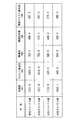
- FIG. 6 is a chart showing estimated values of the seating nipple height and the seating waist base point height. Looking at males 20-29 and 50-59 years old, the seated nipple height and seated waist base height are comparable. Looking at women 20-29 and 50-59 years old, the seating nipple base height is the same, although the seating nipple height is slightly lower at 50-59 years old. In addition, when compared with men and women, the sitting nipple height is lower for women and the seating waist base height is slightly lower for women. Therefore, since the significant difference is the difference in the sitting nipple height seen in men and women, it will be divided into two cases for men and women in the following discussion.
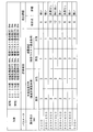
- FIG. 7 is a chart showing the evaluation contents regarding the depth of hot water in a half-body bath.
- the depth of hot water was used as a parameter, 200 mm to 500 mm were divided in 50 mm increments, and half-body bath suitability and appropriate amount of hot water were listed as evaluation items.
- Half body bath suitability is a measure of whether or not it is appropriate as a bathing style aimed at reducing the burden on the heart.
- half-body bathing is often performed by storing hot water below the vicinity of the chest groove. If it is “impossible” as a half-body bath, 1 point is given, 2 points if it is “possible”, and 3 points if it is “appropriate”.
- the hot water surface is about 70 than the average male seated nipple height of 480.4 mm (20-29 years old) and 472.3 mm (50-59 years old).
- hot water is accumulated near or below the groove and is “appropriate (3 points)”.
- the depth of the hot water is 400-450 mm
- the hot water surface approaches the average seating nipple height of men, and it is evaluated that it is about “possible (2 points)”.
- the hot water surface rises from the vicinity of the seated nipple height and is evaluated as “impossible (1 point)”.
- Appropriate amount of hot water means that if the amount of hot water is too small, sufficient half-body bathing will not be possible, so the scale of whether or not the depth of hot water is sufficient. Two points are given for “insufficient”, and three points are given for “sufficient”. As shown in FIG. 7, when the depth of hot water is 250 mm or less, the average seating waist height of males is less than 287.5 mm (20-29 years old) and 287.3 mm (50-59 years old). Evaluated as “insufficient (1 point)”. When the depth of hot water is 250-300 mm, hot water can be stored near the average seating waist base height of men, but it is evaluated as “slightly insufficient (2 points)”. If the depth of the hot water is 300 mm or more, the hot water is accumulated to a level higher than the average seating waist base point for men, and therefore, it is evaluated as “sufficient (3 points)”.
- the appropriate amount of hot water for women is the same as the evaluation of appropriate amount of hot water for men, as it is only about 12.4 mm (compared between 20-29 years old) even where the difference with men with the highest seating waist point is the largest.
- the hot water depth is 300 to 350 mm, the highest being 12 points (evaluation is “good”), and then 350 to 400 mm is 11 points ( “Good”) was obtained.
- the evaluation score was low, and the hot water depth was evaluated as “bad”.
- the hot water depth is 250-300mm, the hot water depth is "slightly insufficient", and when the hot water depth is 400-450mm, the seating nipple height may be exceeded. Became "no good”.
- the stride height H is obtained by adding 130 mm and 20 mm to the typical values of the above-described height H1 and height H3 to the depth of hot water.
- the stride height H is 450 to 500 mm, which is most suitable for half-body bathing, and the peripheral portion 10 of the bathtub 1 can be easily straddled.
- the stride height H exceeds 500 mm, and the difficulty of straddling becomes remarkable, so the evaluation is considered to be lowered.
- the depth of hot water was 250-300mm, the result was that the depth of hot water was "slightly insufficient". It is done.
- the half-body bath can be performed “appropriately” for both men and women, and the bathtub 1 that can easily straddle the peripheral edge 10 of the bathtub 1 is obtained. can get.
- the average value 275 mm in the evaluation category 250-300 mm and the average value 325 mm in the evaluation category 300-350 mm are considered as the nominal value, and the depth H2 may be set to the lower limit 275 mm and the upper limit 325 mm. In this case, when the depth H2 is the upper limit of 325 mm, the stride height H is 475 mm, and straddling ease is further improved.
- the depth H2 of the bathtub 1 is 310 mm
- the height H1 from the floor 111 to the bottom 11 of the bathtub 1 is 132.5 mm
- the height H3 of the lower frame 4c portion is 18.5 mm
- the straddle height H Is 461 mm and it is suitable for half-body bathing, and the bathroom unit 100 can be easily moved inside and outside the bathroom.
- the overflow stopper is provided in the bathtub 1 and the overflow stopper is opened and used so as to discharge hot water
- the depth of the hot water that can be actually stored in the bathtub 1 is the peripheral portion. It will be regulated by an overflow plug at a position below 10.
- the operation of the bathroom unit 100 will be described.
- the user opens and closes the door 2 and moves in and out of the bathroom.
- the guide portion 54 of the lower frame 4c appears on the peripheral edge 10 of the bathtub 1 on the door 2 side.
- the guide portion 54 has the upper surface of the guide portion 54 formed by the facing surface portion 54b, and is easy for the user to wear and put his / her foot on, so that the guide portion 54 can easily move in and out of the bathroom.
- the user can recognize visually that the upper surface of the guide part 54 is formed in the lower frame 4c part, and can receive the impression that it is easy to straddle.
- the outer edge portion 53b of the base portion 53 in the lower frame 4c has an upper surface that is substantially the same height as the upper surface of the guide portion 54, it is easier for the user to wear hands and put feet on, so Movement becomes even easier.
- the user can recognize that a wide range of surfaces are formed in the lower frame 4c, and can easily receive an impression that it is easy to straddle.
- the first packing 55 and the first packing 56 are arranged so as to protrude in the prospective direction and partially cover the guide groove 54c and the guide groove 54d. For this reason, the guide groove 54c and the guide groove 54d are partially blocked by the first packing 55 and the first packing 56, and the upper surface of the guide portion 54 is widened. Moving into and out of the bathroom is even easier. Further, the user can recognize that a wider area is formed in the lower frame 4c, and is more likely to receive an impression that it is easy to straddle.
- the depth H2 of the bathtub 1 is set to 250 mm or more and 350 mm or less.
- the straddling height H is a typical value of 130 mm of the height H1 from the floor 111 to the bottom 11 of the bathtub 1 and a typical height H3 of the lower frame 4c portion. It becomes 400 mm or more and 500 mm or less which added the value 20 mm.
- the bathroom unit 100 can perform a half body bath in the bathtub 1 "appropriately" for both men and women, and the peripheral edge 10 of the bathtub 1 can be easily straddled, and the movement inside and outside the bathroom is facilitated. Bathtub 1 is obtained.
- the average value 275 mm in the evaluation category 250-300 mm and the average value 325 mm in the evaluation category 300-350 mm may be considered as the nominal value, and the depth H2 may be the lower limit 275 mm and the upper limit 325 mm. In this case, when the depth H2 is the upper limit of 325 mm, the stride height H is 475 mm, and straddling ease is further improved.
- the bathroom unit 100 includes a bathtub 1 that stores hot water, a trap portion 71 that is disposed below the bathtub 1, and a wall that is disposed on the peripheral portion 10 of the bathtub 1 so as to surround the bathtub 1.
- Body 61a, 61b and 61c, the door 2, and the frame part 4 which fits the door 2 are provided.
- the frame portion 4 has a lower frame 4 c disposed on the peripheral edge portion 10.
- the bathroom unit 100 has a depth H2 from the peripheral edge 10 to the bottom 11 of the bathtub 1 of 350 mm or less, and a height from the floor 111 to be installed to the upper end of the lower frame 4c, that is, the straddle height H is 500 mm or less. is there.
- the bathtub 1 is suitable for half-body bathing, and can easily move in and out of the bathroom.
- the bathroom unit 100 has a depth H2 from the peripheral edge 10 to the bottom 11 of the bathtub 1 of 325 mm or less, and the height from the floor 111 to be installed to the upper end of the lower frame 4c, that is, the straddle height H is 475 mm. It is as follows. Thereby, the bathroom unit 100 becomes still easier to move in and out of the bathroom.
- the bathroom unit 100 has a depth H2 from the peripheral edge 10 to the bottom 11 of the bathtub 1 of 275 mm or more, and the height from the floor 111 to be installed to the upper end of the lower frame 4c, that is, the straddle height H is 425 mm. That's it.
- the bathtub 1 is suitable for a half body bath.
- the bathroom unit 100 includes a bathtub 1 that stores hot water, a trap portion 71 that is disposed below the bathtub 1, and a wall body 61 a that is disposed on the peripheral portion 10 of the bathtub 1 so as to surround the bathtub 1.
- 61b and 61c, the door 2, and the frame part 4 which fits the door 2 are provided.
- the opposing surface part 54b is formed in the highest position in the lower frame 4c. Thereby, a user can touch the opposing surface part 54b in the highest position among the lower frames 4c with a limb first.
- the door 2 may be a sliding door, a folding door, or the like.
- the bathroom unit 100 of the second embodiment is configured in the same manner as the bathroom unit 100 described in the first embodiment with reference to FIGS. 1 to 7.
- the bathroom unit 100 includes a bathtub 1, a door 2, a frame part 4, a wall part 61, a drainage part 7, an apron part 63, and the like.
- the frame portion 4 in the bathroom unit 100 configured and operates in the same manner as in the first embodiment will be described in detail.
- the frame portion 4 includes the left vertical frame 4a, the right vertical frame 4b, the lower frame 4c, the upper frame 4d, and the lower end frame 4e.
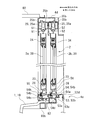
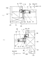
- FIG. 8 is a cross-sectional view of the bathroom unit 100 along the line BB shown in FIG.
- FIG. 8 also shows an outer wall plate 101 and the like that are constructed as a decorative plate on the indoor side when the bathroom unit 100 is installed indoors, and a square member 91 and the like to which the outer wall plate is attached.
- a square member 91 extending in the vertical direction is provided outside the left vertical frame 4 a, and the outer wall plate 101 is attached to the front side of the square member 91.
- a plurality of square members 92 extending in the vertical direction are provided along the wall body 61 b on the left vertical frame 4 a side, and an outer wall plate 102 is attached to the front side of the square members 92.
- Wallpaper or the like is attached to the surfaces of the outer wall plate 101 and the outer wall plate 102.
- a square member 93 extending in the vertical direction is provided outside the right vertical frame 4b.
- Square member 93 is in contact with indoor building side wall surface 110.
- An outer wall plate 103 is attached to the front side of the square member 93.
- the bathroom unit 100 is installed such that the side surface on the wall body 61b side is in contact with a plurality of square members 94 extending along the vertical direction provided along the side wall surface 110 of the building.
- a square member 95 extending in the vertical direction along the building side wall surface 110 is provided outside the door 2 on the building side wall surface 110, and an outer wall plate 104 is attached to the front side of the square member 95. Wallpaper or the like is attached to the surfaces of the outer wall plate 103 and the outer wall plate 104.
- FIG. 9 (a) is an enlarged view of the left vertical frame 4a portion in FIG. 8, and FIG. 9 (b) is an enlarged view of the right vertical frame 4b portion in FIG.
- the left vertical frame 4 a includes an inner left vertical frame 41, an outer left vertical frame 42, and an angle piece portion 43.
- the inner left vertical frame 41 has a rectangular tube shape, is disposed so as to overlap the peripheral portion 10 of the bathtub 1, and is fixed to a vertical column 81 provided at a corner portion of the peripheral portion 10. .
- a wall body 61 b is also fixed to the support column 81.
- the inner left vertical frame 41 is formed from the peripheral edge 10 of the bathtub 1 to the ceiling 62.
- the outer left vertical frame 42 has a rectangular tube shape, is continuously formed in the prospective direction on the inner left vertical frame 41, and is disposed outside the peripheral edge portion 10 of the bathtub 1.
- the outer left vertical frame 42 is formed over the entire length of the left vertical frame 4a.
- the angle piece portion 43 is continuous with the outer left vertical frame 42 and is provided so as to protrude in the prospective direction outside the outer left vertical frame 42.
- the angle piece portion 43 is formed over the entire length of the left vertical frame 4 a in the same manner as the outer left vertical frame 42.
- the right vertical frame 4 b has an inner right vertical frame 46, an outer right vertical frame 47, and an angle piece portion 48.
- the inner right vertical frame 46 has a rectangular tube shape, is disposed so as to overlap the peripheral portion 10 of the bathtub 1, and is fixed to a vertical column 81 provided at a corner portion of the peripheral portion 10. .
- a wall body 61 c is also fixed to the support column 81.
- the inner right vertical frame 46 is formed from the peripheral edge 10 of the bathtub 1 to the ceiling 62.
- the outer right vertical frame 47 has a rectangular tube shape, is continuously formed in the prospective direction on the inner right vertical frame 46, and is disposed outside the peripheral edge portion 10 of the bathtub 1.
- the outer right vertical frame 47 is formed over the entire length of the right vertical frame 4b.
- the angle piece portion 48 is continuous with the outer right vertical frame 47 and is provided on the outer side of the outer right vertical frame 47 so as to protrude in the prospective direction.
- the angle piece portion 48 is formed over the entire length of the right vertical frame 4 b in the same manner as the outer right vertical frame 47.
- FIG. 10 is a cross-sectional view of the bathroom unit 100 along the line CC shown in FIG.
- FIG. 10 also shows an outer wall plate 101 and the like that are constructed as a decorative plate on the indoor side when the bathroom unit 100 is installed indoors, and a square member 91 and the like that attach the outer wall plate.
- FIG. 10 shows a horizontal cross section below the peripheral edge 10 of the bathtub 1.
- the square member 91 is in contact with the outside of the left vertical frame 4a, and an outer wall plate 101 is attached to the front side.
- An outer wall plate 102 is attached to the front side of a plurality of square members 92 extending in the vertical direction.
- the square member 93 abuts on the indoor building side wall surface 110, abuts on the outside of the right vertical frame 4b, and an outer wall plate 103 is attached to the front side.
- FIG. 11 (a) is an enlarged view of the left vertical frame 4a portion in FIG. 10, and FIG. 11 (b) is an enlarged view of the right vertical frame 4b portion in FIG.
- the left vertical frame 4 a is formed of an outer left vertical frame 42 and an angle piece portion 43, in which a portion of the inner left vertical frame 41 is cut off below the peripheral edge portion 10 of the bathtub 1.
- the right vertical frame 4 b is formed of an outer right vertical frame 47 and an angle piece portion 48, with a portion of the inner right vertical frame 46 cut away from the peripheral edge 10 of the bathtub 1.
- An apron portion 63 is detachably attached to a region between the left vertical frame 4a and the right vertical frame 4b.
- FIG. 12 is a cross-sectional view of the bathroom unit 100 along the line AA shown in FIG.
- the cross section of the bathroom unit 100 shown in FIG. 12 is the same as the cross section shown in FIG. 3, but the outer wall plate 105 and the like are added.
- the bathroom unit 100 is placed on the indoor floor 111.
- a drainage unit 7 connected to the drainage port 12 is provided in a space between the floor.
- the lower end frame 4e is close to the floor 111 so as to be in contact with the floor 111 or to have a slight gap.
- the apron portion 63 is attached to a region between the lower frame 4c and the lower end frame 4e.
- An angle piece portion 59 is formed on the upper frame 4d so as to protrude to the outside of the bathroom unit 100 in the prospective direction.
- the angle piece portion 59 is formed over the entire length of the upper frame 4d.
- the outer wall plate 105 to be constructed as a decorative plate on the indoor side is attached so as to contact the angle piece portion 59.
- the door 2 is a sliding door, and can open and close both the inner shoji 2a and the outer shoji 2b (see FIG. 1).
- the user can enter the interior of the bathroom unit 100 from the wall 61b side by opening the inner shoji 2a, and can reach out to various devices inside the bathroom unit 100 from the outside of the bathroom unit 100. Can be operated.
- the user can enter the bathroom unit 100 from the wall 61c side by opening the external shoji 2b, and can reach from the outside of the bathroom unit 100 to various devices inside the bathroom unit 100. Can be operated. For example, the user can perform operations such as opening and closing a drain plug (not shown) provided at the drain port 12 by opening the external shoji 2b.
- the door 2 is fitted in the frame part 4.
- the frame part 4 has a left vertical frame 4a and a right vertical frame 4b that extend linearly from below to above the peripheral edge 10 of the bathtub 1.
- the lower ends of the left vertical frame 4a and the right vertical frame 4b are close to the floor 111 so as to be in contact with the floor 111 (see FIG. 2) on which the bathroom unit 100 is placed or to leave a slight gap.
- FIG. 9A when installing the bathroom unit 100 on the indoor floor 111, the worker attaches the outer wall plate 101 to the outside of the left vertical frame 4 a as a decorative plate on the indoor side of the bathroom unit 100.
- 9B the worker attaches the outer wall plate 103 to the outside of the right vertical frame 4b as a decorative plate on the indoor side of the bathroom unit 100.
- the outer wall plate 101 and the outer wall plate 103 may be cut into an elongated right-angle shape, that is, a strip shape.
- the worker simply arranges the strip-shaped outer wall plate 101 on the surface of the square member 91 on the left vertical frame 4a side and arranges the angle piece portion 43 so as to follow the side portion of the outer wall plate 101.
- the outer wall plate 101 can be easily constructed.
- the worker attaches the strip-shaped outer wall plate 103 to the surface of the square member 93 on the right vertical frame 4b side, and attaches the side piece of the outer wall plate 103 to the angle piece portion 48 by a simple operation.
- the outer wall plate 103 can be easily constructed.
- the lower ends of the left vertical frame 4a and the right vertical frame 4b are close to the floor 111 so as to be in contact with the floor 111 on which the bathroom unit 100 is placed or have a slight gap, and the lower ends are connected by the lower frame 4e. is doing.
- An apron portion 63 is detachably provided in a region below the door 2 and surrounded by the left vertical frame 4a, the right vertical frame 4b, the lower frame 4c, and the lower end frame 4e. The operator can perform work such as inspection or repair of the drainage part 7 provided below the bathtub 1 by removing the apron part 63.
- the gap on the floor 111 side of the lower end frame 4e is eliminated, and an outer wall plate is provided below the frame portion 4. There is no need to provide it, and the construction of the outer wall plate is facilitated.
- the outer wall plate 102 is cut out in a right-angle shape and becomes a decorative plate provided outside the wall unit 61b side of the bathroom unit 100, but may be attached so as to follow the front side of the plurality of square members 92.
- the outer wall plate 104 may be cut into a right-angle shape and attached so as to follow the front side of the square member 95 provided on the building side wall surface 110.
- the angle piece 59 is formed on the upper frame 4d so as to protrude outside the bathroom unit 100 in the prospective direction.
- the outer wall plate 105 to be constructed as a decorative panel on the indoor side can be cut into a strip shape and attached so as to come into contact with the angle piece portion 59, so that the construction of the outer wall plate 105 is facilitated.
- the bathroom unit 100 includes a bathtub 1 that stores hot water, wall bodies 61a, 61b, and 61c that are disposed on the peripheral edge 10 of the bathtub 1 so as to surround the bathtub 1, the door 2, and the door 2.
- the frame part 4 which fits.
- the frame part 4 has a left vertical frame 4a and a right vertical frame 4b extending from the lower side of the peripheral edge part 10 of the bathtub 1 to the upper side.
- the bathroom unit 100 can attach the outer wall board 101 and the outer wall board 103 by the simple operation
- the construction of the outer wall board becomes easy.
- the bathroom unit 100 is provided with a detachable apron portion 63 below the peripheral edge portion 10 of the bathtub 1 and between the left vertical frame 4a and the right vertical frame 4b. Thereby, the bathroom unit 100 can shield the lower part of the peripheral part 10 of the bathtub 1 by the apron part 63. The bathroom unit 100 can inspect and repair the drainage part 7 provided below the bathtub 1 by removing the apron part 63.
- the left vertical frame 4a and the right vertical frame 4b extend to the floor 111 to be installed.
- the frame portion 4 has a lower end frame 4e that connects lower end portions of the left vertical frame 4a and the right vertical frame 4b.
- the bathroom unit 100 is close to the floor 111 so that the lower end frame 4e is in contact with the floor 111 or has a slight gap, and there is no need to provide an outer wall plate on the lower side of the frame portion 4. Becomes easy.
- (Modification) 13 is a cross-sectional view corresponding to a cross section taken along line BB of FIG. 2 in a bathroom unit 100 according to a modification.
- a frame portion 96 is provided in the frame portion 4.
- a square member 91 extending in the vertical direction is provided outside the frame portion 96, and the outer wall plate 101 is attached to the front side of the square member 91.
- the outer wall plate 102 is attached in the same manner as in the above-described embodiment.
- a square member 93 extending in the vertical direction is provided outside the frame portion 96. Square member 93 is in contact with indoor building side wall surface 110.
- An outer wall plate 103 is attached to the front side of the square member 93.
- FIG. 14 (a) is an enlarged view of the left vertical frame 4a portion in FIG. 13, and FIG. 14 (b) is an enlarged view of the right vertical frame 4b portion in FIG.
- the left vertical frame 4a includes an inner left vertical frame 41, an outer left vertical frame 42, and an angle piece portion 43, as in the above-described embodiment.
- the frame portion 96 is formed so as to be connected to the angle piece portion 43 on the outer side in the prospective direction of the left vertical frame 4a.
- the frame portion 96 extends from the floor 111 to the ceiling 62 along the outer left vertical frame 42 and the angle piece portion 43.
- the right vertical frame 4 b includes an inner right vertical frame 46, an outer right vertical frame 47, and an angle piece portion 48.
- the frame portion 96 is formed so as to be connected to the angle piece portion 48 on the outer side in the prospective direction of the right vertical frame 4b.
- the frame portion 96 extends from the floor 111 to the ceiling 62 along the outer right vertical frame 47 and the angle piece portion 48.
- FIG. 15 is a cross-sectional view corresponding to a cross section taken along line CC of FIG. 2 in a bathroom unit 100 according to a modification.
- FIG. 15 shows a horizontal cross section below the peripheral edge 10 of the bathtub 1.
- a square member 91 extending in the vertical direction is provided outside the frame portion 96, and the outer wall plate 101 is attached to the front side of the square member 91.
- a square member 93 extending in the vertical direction is provided outside the frame portion 96, and an outer wall plate 103 is attached to the front side of the square member 93.
- FIG. 16 (a) is an enlarged view of the left vertical frame 4a portion in FIG. 15, and FIG. 16 (b) is an enlarged view of the right vertical frame 4b portion in FIG.
- the left vertical frame 4 a is formed of an outer left vertical frame 42 and an angle piece portion 43, in which a portion of the inner left vertical frame 41 is cut off below the peripheral edge portion 10 of the bathtub 1.
- the frame portion 96 may be formed so as to follow the outer left vertical frame 42 and the angle piece portion 43 extending from the floor 111 to the ceiling 62, and can be easily constructed.
- the right vertical frame 4 b is formed of an outer right vertical frame 47 and an angle piece portion 48, with a portion of the inner right vertical frame 46 cut away from the peripheral edge 10 of the bathtub 1.
- the frame portion 96 may be formed so as to follow the outer right vertical frame 47 and the angle piece portion 48 extending from the floor 111 to the ceiling 62, and can be easily constructed.
- the door 2 may be a sliding door, a folding door, a hinged door, or the like.
- the lower end frame 4e may be disposed slightly away from the floor surface, and an outer wall plate may be attached between the lower end frame 4e and the floor 111.
- the frame portion 4 may be sized according to the vertical and horizontal dimensions of the door 2.
- the left vertical frame 4a and the right vertical frame 4b have been shown with examples in which the upper end side extends substantially to the height position of the ceiling 62, but according to the vertical dimension of the door 2 What is necessary is just to extend upward from the peripheral part 10 of the bathtub 1 by the length dimension, and does not need to extend to the height position of the ceiling 62.
- the lower frame 4c, the upper frame 4d, and the lower end frame 4e may have length dimensions corresponding to the lateral dimensions of the door 2.
- the lower frame 4c extends over the entire edge portion 10 of the bathtub 1 and may be partially provided narrower than between both ends.
- the upper frame 4d and the lower frame 4e are also provided on the lower frame 4c. The combined dimensions may be used.
- the bathroom unit 100 of Embodiment 3 is configured in the same manner as the bathroom unit 100 described in Embodiments 1 and 2 with reference to FIGS.
- the bathroom unit 100 includes a bathtub 1, a door 2, a frame part 4, a wall part 61, a drainage part 7, and the like.
- the prevention of outflow of hot water in the frame part 4 of the bathroom unit 100 that is configured and operates in the same manner as in the first and second embodiments will be described in detail.
- the frame portion 4 includes the left vertical frame 4a, the right vertical frame 4b, the lower frame 4c, the upper frame 4d, and the lower end frame 4e.
- the first packing 55 is provided at the edge of the opening of the guide groove 54c, and the first packing 56 is provided at the edge of the opening of the guide groove 54d.
- the 1st packing 55 contacts the to-be-guided plate 26 provided in the lower collar 23 of the inner impeller 2a.
- the 1st packing 56 contacts the to-be-guided plate 36 provided in the lower collar 33 of the external obstacle 2b.
- the first packing 55 and the first packing 56 are provided from the left vertical frame 4a to the right vertical frame 4b.
- the spacers 57 disposed at both ends of the guide portion 54 in the direction of finding are provided on the spacer 57. Not provided.
- the first packing 55 and the first packing 56 prevent the water from flowing out from the bathroom unit 100 through the door 2 by closing the gaps in the guide groove 54c and the guide groove 54d.
- the first packing 55 and the first packing 56 are disposed so as to protrude in the prospective direction and partially cover the guide groove 54c and the guide groove 54d.
- the opposing surface portion 54b is separated into three portions by two guide grooves 54c, but the area of the upper surface of the guide portion 54 formed by each portion is wider than the opening area of the guide groove 54c. Moreover, since the 1st packing 55 and the 1st packing 56 protrude in the prospective direction from the edge of the opening part of the guide groove 54c and the guide groove 54d, the opening area of the guide groove 54c becomes smaller.
- FIG. 17 is a perspective view of the end portion of the lower frame 4c.
- the spacer 57 has a guide groove 57 c that is continuous with the guide groove 54 c of the guide portion 54 and a notch portion 57 d that is notched on the left vertical frame 4 a side, and is detachably attached to the base portion 53.
- the opening width of the guide groove 57c of the spacer 57 is narrower than that of the guide groove 54c of the guide portion 54, and no packing is provided.
- the notch 57d is provided on the outer side opposite to the bathtub 1 side of the inner shoji 2a. Since the spacer 57 is not provided with packing, hot water may flow into the guide groove 57c.
- the spacer 57 is provided in order to remove the guide part 54 by putting a finger on the end part of the guide part 54 by removing the spacer 57 from the base part 53.
- the guide portion 54 is divided into three substantially equally in the direction of finding, and is connected by providing thin plate-like cover pieces (not shown) at two joints of each portion. It is easy to bend at one part.
- the spacer 57 is removed from the base portion 53 as described above, a part of the guide portion 54 is lifted upward, bent upward at the joint portion, and further the guide portion 54 The remaining portion of 54 is pulled out in the direction of finding from the bottom of the inner and outer obstacles 2a and 2b.
- FIG. 18 is a perspective view of the bottom of the Tojiri ridge 22 of the inner shoji 2a
- FIG. 19 is an end view of the bottom of the Tojiri ridge 22 of the inner shoji 2a.
- a cap 58 is attached to the bottom of the Tojiri bowl 22.
- the cap 58 has a plate-like shape, and has a protruding portion 58 a that protrudes from the bottom portion and fits into the guide groove 54 c of the guide portion 54.
- a second packing 58b is provided at the bottom of the cap 58 over the entire width of the door ridge 22 in the expected direction.
- the second packing 58 b comes into contact with the inner side surface and the bottom surface of the guide groove 54 c of the guide portion 54 and the first packing 55 at the protruding portion 58 a.
- the second packing 58 b comes into contact with the facing surface portion 54 b of the guide portion 54.
- the second packing 58b is in contact with the guided plate 36 on the side of the external obstacle 2b, and continues to a third packing 22a described later.
- the left vertical frame 4a includes an inner left vertical frame 41, an outer left vertical frame 42, an angle piece portion 43, and a fourth packing 44a.
- the inner left vertical frame 41 has a rectangular tube shape, is disposed so as to overlap the peripheral portion 10 of the bathtub 1, and is fixed to a vertical column 81 provided at a corner portion of the peripheral portion 10. .
- the inner left vertical frame 41 is formed from the peripheral edge 10 of the bathtub 1 to the ceiling 62.
- the outer left vertical frame 42 has a rectangular tube shape, is continuously formed in the prospective direction on the inner left vertical frame 41, and is disposed outside the peripheral edge portion 10 of the bathtub 1.
- the outer left vertical frame 42 is formed over the entire length of the left vertical frame 4a.
- the angle piece portion 43 is continuous with the outer left vertical frame 42 and is provided so as to protrude in the prospective direction outside the outer left vertical frame 42.
- the angle piece portion 43 is formed over the entire length of the left vertical frame 4 a in the same manner as the outer left vertical frame 42.
- the 4th packing 44a is attached to the wall part 44 which protrudes in the direction of finding from the center part of the prospective direction of the left vertical frame 4a.
- the 4th packing 44a is arrange
- the fourth packing 44a may be disposed from the lower frame 4c to the upper frame 4d, or is disposed from the lower frame 4c to the central portion between the lower frame 4c and the upper frame 4d. May be.
- the 4th packing 44a contacts the front-end
- the right vertical frame 4b includes an inner right vertical frame 46, an outer right vertical frame 47, an angle piece portion 48, and a fourth packing 49a.
- the inner right vertical frame 46 has a rectangular tube shape, is disposed so as to overlap the peripheral portion 10 of the bathtub 1, and is fixed to a vertical column 81 provided at a corner portion of the peripheral portion 10. .
- the inner right vertical frame 46 is formed from the peripheral edge 10 of the bathtub 1 to the ceiling 62.
- the outer right vertical frame 47 has a rectangular tube shape, is continuously formed in the prospective direction on the inner right vertical frame 46, and is disposed outside the peripheral edge portion 10 of the bathtub 1.
- the outer right vertical frame 47 is formed over the entire length of the right vertical frame 4b.
- the angle piece portion 48 is continuous with the outer right vertical frame 47 and is provided on the outer side of the outer right vertical frame 47 so as to protrude in the prospective direction.
- the angle piece portion 48 is formed over the entire length of the right vertical frame 4 b in the same manner as the outer right vertical frame 47.
- the 4th packing 49a is attached to the wall part 49 which protrudes in the direction of finding from the center part of the prospective direction of the right vertical frame 4b. Similar to the inner right vertical frame 46, the wall portion 49 is formed from the peripheral edge 10 of the bathtub 1 to the ceiling 62.
- the fourth packing 49a may be disposed from the lower frame 4c to the upper frame 4d, or from the lower frame 4c to the central portion between the lower frame 4c and the upper frame 4d. May be.
- the 4th packing 49a contacts the front-end
- the fourth packing 44a is disposed not in the bathtub 1 side of the inner shoji 2a but in the central portion in the prospective direction of the left vertical frame 4a, and the fourth packing 49a is also disposed in the central portion in the prospective direction of the right vertical frame 4b.
- the width dimension of the prospective direction of the whole frame part 4 can be restrained small.
- the Tojiri kite 22 of the inner shoji 2a has a third packing 22a on the side surface of the outer shoji 2b on the Tojiri kite 32 side at the end in the prospective direction.
- the third packing 22a contacts the side surface of the Tojiri heel 32 on the Tojiri heel 22 side, and the lower end portion is continuous with the second packing 58b.
- the third packing 22a may be disposed from the lower frame 4c to the upper frame 4d, or is disposed from the lower frame 4c to the central portion between the lower frame 4c and the upper frame 4d. May be.
- FIG. 21 is a schematic diagram for explaining a sealing portion by packing between the door 2 and the frame portion 4.
- a portion where the packing is provided is indicated by a thick solid line
- a portion where the packing is provided in a direction perpendicular to the paper surface is indicated by a black circle.
- a gap between the lower collar 23 and the lower frame 4c which is the bottom of the door 2 with respect to the inner shoji 2a, is generated between the guided plate 26 of the lower collar 23 and the guide groove 54c of the lower frame 4c. Is sealed by the first packing 55.
- a gap between the lower rod 33 and the lower frame 4c which is the bottom of the door block 2b, may occur between the guided plate 36 of the lower rod 33 and the guide groove 54d of the lower frame 4c. Is sealed by the first packing 56.
- the bathroom unit 100 can seal the gap between the door 2 and the frame part 4 in most of the lower frame 4c, and hot water used in the bathroom unit 100 flows out from the door 2 to the outside. Can be prevented.
- the spacer 57 Since the spacer 57 is provided at the end of the lower frame 4c, a gap is generated between the bottom of the door 2 and the lower frame 4c by the width of the spacer 57. However, as described above, the spacer 57 is provided in the spacer 57. Since hot water that has flowed out from the notch 57d to the seat 53a of the base 53 flows into the bathtub 1 and returns to the bathtub 1, the outflow of hot water to the outside of the bathroom unit 100 can be prevented.
- the gap between the bottom of the door 2 and the lower frame 4c may be generated at the bottom of the Tojiri ridge 22 of the inner shoji 2a, but is sealed by the second packing 58b.
- the second packing 58b is provided along the prospective direction, contacts the inner side surface and the bottom surface of the guide groove 54c, and continues to the first packing 55 and the guided plate 36 of the outer panel 2b. Thereby, the bathroom unit 100 can enhance the sealing effect of the gap between the door 2 and the lower frame 4c.
- the third packing 22a is disposed from the lower frame 4 c to the central portion between the lower frame 4 c and the upper frame 4 d, that is, the central portion in the vertical direction of the door 2.
- it may be extended from the lower frame 4c to the upper frame 4d as shown by a dotted line in FIG. Thereby, the bathroom unit 100 can prevent the hot water from flowing out to the outside through the gap generated in the door 2.
- the bathroom unit 100 can provide the air inlet at a position where it is difficult for outside users to hit the bathing user.
- a gap may be generated between the door toe 21 of the inner shoji 2a and the left vertical frame 4a and between the door toe 31 of the outer shoji 2b and the right vertical frame 4b. It is sealed with 4 packings 49a.
- the fourth packing 44a and the fourth packing 49a extend from the lower frame 4c to the central portion between the lower frame 4c and the upper frame 4d, that is, the central portion in the vertical direction of the door 2 as shown by a thick solid line in FIG. Alternatively, they may be extended from the lower frame 4c to the upper frame 4d as shown by the dotted line in FIG. Thereby, the bathroom unit 100 can prevent the hot water from flowing out to the outside through the gap generated between the door 2 and the left vertical frame 4a and the right vertical frame 4b.
- the bathroom unit 100 can provide the air inlet at a position where it is difficult for outside users to hit the bathing user.
- the bathroom unit 100 includes a bathtub 1 that stores hot water, wall bodies 61a, 61b, and 61c that are disposed on the peripheral edge 10 of the bathtub 1 so as to surround the bathtub 1, the door 2, and the door 2.
- the frame part 4 which fits.
- the frame part 4 has a lower frame 4 c disposed on the peripheral edge part 10.
- the 1st packing 55 seals the clearance gap between the lower collar 23 and the lower frame 4c which are the bottom parts in the door 2 of the door 2.
- the 1st packing 56 seals the clearance gap between the lower collar 33 and the lower frame 4c which are the bottom parts in the external obstacle 2b of the door 2.
- the bathroom unit 100 can seal the gap between the door 2 and the frame part 4 in most of the lower frame 4c, and hot water used in the bathroom unit 100 flows out from the door 2 to the outside. Can be prevented.
- the door 2 is a sliding door
- a second packing 58b is provided that seals a gap between the bottom of the door butt ridge 22 and the lower frame 4c in the door 2 of the door 2 and extends in a prospective direction.
- the bathroom unit 100 can improve the sealing effect of the clearance gap between the door 2 and the lower frame 4c.
- the bathroom unit 100 seals the gap between the door butt cage 22 in the door 2 of the door 2 and the door butt cage 32 of the door 2 of the door 2 and has one end connected to the second packing 58b in the vertical direction.
- the 3rd packing 22a extended in this is provided.
- the bathroom unit 100 seals the gap between the door toe 21 of the inner shoji 2a and the door toe 31 of the outer shoji 2b and the left vertical frame 4a and the right vertical frame 4b, which are the vertical frames of the door 2,
- a fourth packing 44a and a fourth packing 49a extending upward from the lower frame 4c are provided. Thereby, the bathroom unit 100 can prevent hot water from flowing out to the outside through the gap generated between the door 2, the left vertical frame 4a and the right vertical frame 4b, and the gap generated in the door 2. it can.
- the 4th packing 44a and the 4th packing 49a are extended to the middle part in the up-down direction of the door 2. As shown in FIG. Thereby, the bathroom unit can make the clearance between the center part and the upper frame 4d an intake port through which air is sucked during ventilation, making it difficult for outside users to hit the bathing room.
- the door 2 may be a sliding door or the like.
- the frame portion 4 may be sized according to the vertical and horizontal dimensions of the door 2.
- the left vertical frame 4a and the right vertical frame 4b have shown an example in which the upper end side extends substantially to the height position of the ceiling 62, but the length dimension according to the vertical dimension of the door 2 is shown. Therefore, it only has to extend upward from the peripheral edge 10 of the bathtub 1, and does not have to extend to the height position of the ceiling 62.
- the lower frame 4c, the upper frame 4d, and the lower end frame 4e may have length dimensions corresponding to the lateral dimensions of the door 2.
- the lower frame 4c extends over the entire edge portion 10 of the bathtub 1 and may be partially provided narrower than between both ends.
- the upper frame 4d and the lower frame 4e are also provided on the lower frame 4c. The combined dimensions may be used.
- the present invention relates to a bathroom unit.
Landscapes
- Engineering & Computer Science (AREA)
- Health & Medical Sciences (AREA)
- Public Health (AREA)
- Architecture (AREA)
- Civil Engineering (AREA)
- Structural Engineering (AREA)
- Epidemiology (AREA)
- General Health & Medical Sciences (AREA)
- Residential Or Office Buildings (AREA)
Abstract
浴室ユニット100は、湯を溜める浴槽1と、浴槽1の下方に配設されたトラップ部71と、浴槽1を囲繞するように浴槽1の周縁部10に配設された壁体61a等および扉2と、扉2を嵌める枠部とを備える。枠部は周縁部10に配設された下枠4cを有する。浴室ユニット100は、周縁部10から浴槽1の底部11までの深さH2が350mm以下であり、設置する床111から下枠4cの上端部までの高さ、即ち跨ぎ高さHが500mm以下である。
Description
本発明は、浴室ユニットに関する。
近年では、専らシャワー装置から吐出される湯水を浴び、浴槽に溜めた湯に浸かることなく入浴を行う生活様式が見られるようになってきた。このような生活様式に合わせて、シャワー装置から吐出された湯水を受ける防水パンと、該防水パンを囲繞するように配設された壁部とを備えるコンパクトな浴室ユニットが考案されている。
例えば、特許文献1には、入浴可能な深さに湯を溜めることができる深型の防水パンを有し、防水パンの周縁部に配設された壁部もしくは天井部にシャワー装置を設けた浴室ユニットが開示されている。防水パンは、内部に湯を落とし込むための給湯手段を有しており、湯を溜めるための浴槽として機能する。防水パンには、給湯手段のほか、排水栓およびオーバーフロー用排水口が設けられている。また、浴室ユニットは、正面側に出入口を設けて扉を開閉自在に取り付けてある。
また、特許文献2には、バスルームとトイレルームを別部屋にした浴室ユニットが開示されている。この浴室ユニットは、床面の一方側に設けられた浴槽と、該床面の他方側に設けられた便器と、浴槽と便器との間に配設されたサッシとを備える。浴室ユニットは、サッシによってバスルームとトイレルームとに仕切られる。
特許文献1に記載の浴室ユニットは、排水栓およびオーバーフロー用排水口からの排水を建築側排水口へ流す排水部を防水パン下に設ける必要がある。特許文献1には、防水パン下に設ける排水部に関する記述が見られないものの、排水部がトラップ機能を有するような場合には排水部の高さ方向の寸法が大きくなり、これに伴って防水パンの周縁部の位置も高くなる。浴室ユニットは、正面側に設けられた出入口において防水パンの周縁部をユーザが跨いで移動する際に、防水パンの周縁部が高い位置にあると、跨ぎ難くなるという問題点があった。
浴室ユニットは、例えば見付け方向に延びる薄板状のレールが扉の下枠部分に突起していると、該下枠部分が設けられる防水パンの周縁部に手を着き難く、また足を載せ難くなるため、出入口が跨ぎ難いという印象をユーザに与えてしまう。
第1発明は、斯かる事情に鑑みてなされたものであり、その目的とするところは、浴槽が壁体および扉で囲繞されており、浴室内外への移動が容易な浴室ユニットを提供することにある。
また特許文献1に記載の浴室ユニットは、室内にどのように設置されるかについて記述が見られないものの、設置する際に室内側の化粧板となる外壁板の施工が容易となるよう配慮する必要がある。とくに浴室ユニットの扉部分における枠部周囲の外壁板は、枠部の形状や構成に拠っては、施工に手間がかかってしまうという問題点があった。
第2発明は、斯かる事情に鑑みてなされたものであり、その目的とするところは、浴槽が壁体および扉で囲繞されており、外壁板の施工が容易な浴室ユニットを提供することにある。
特許文献2に記載の浴室ユニットは、サッシによってバスルームが仕切られているが、バスルーム内で使用した湯水のトイレルーム側への流出を防止する手段は見られず、湯水がトイレルーム側へ流出する蓋然性があった。浴室ユニットは、バスルーム内で使用した湯水がトイレルーム側へ流出した場合、トイレルーム側に溜まった水を拭き取る手間がかかってしまう。
第3発明は、斯かる事情に鑑みてなされたものであり、その目的とするところは、浴槽が壁体および扉で囲繞されており、扉からの湯水の流出を防止することができる浴室ユニットを提供することにある。
第1発明のある態様は浴室ユニットである。この浴室ユニットは、湯を溜める浴槽と、前記浴槽の下方に配設されたトラップ部と、前記浴槽を囲繞するように前記浴槽の周縁部に配設された壁体および扉と、前記扉を嵌める枠部と、を備える浴室ユニットにおいて、前記枠部は前記周縁部に配設された下枠を有し、前記周縁部から前記浴槽の底部までの深さが350mm以下であり、設置する床から前記下枠の上端部までの高さが500mm以下であることを特徴とする。
第1発明の別の態様に係る浴室ユニットは、湯を溜める浴槽と、前記浴槽の下方に配設されたトラップ部と、前記浴槽を囲繞するように前記浴槽の周縁部に配設された壁体および扉と、前記扉を嵌める枠部と、を備える浴室ユニットにおいて、前記枠部は前記周縁部に配設された下枠に、前記扉の底部に対向する対向面部が形成されていることを特徴とする。
第2発明のある態様は浴室ユニットである。この浴室ユニットは、湯を溜める浴槽と、前記浴槽を囲繞するように前記浴槽の周縁部に配設された壁体および扉と、前記扉を嵌める枠部と、を備える浴室ユニットにおいて、前記枠部は、前記周縁部の下方から上方に亘って延びる左縦枠および右縦枠を有することを特徴とする。
第3発明のある態様は浴室ユニットである。この浴室ユニットは、湯を溜める浴槽と、前記浴槽を囲繞するように前記浴槽の周縁部に配設された壁体および扉と、前記扉を嵌める枠部と、を備える浴室ユニットにおいて、前記枠部は前記周縁部に配設された下枠を有し、前記扉の底部と前記下枠との隙間を封止する第1シール部材が設けられていることを特徴とする。
第1発明によれば、浴室ユニットは、浴槽が壁体および扉で囲繞されており、浴室内外への移動が容易である。
第2発明によれば、浴室ユニットは、浴槽が壁体および扉で囲繞されており、外壁板の施工が容易となる。
第3発明によれば、浴室ユニットは、浴槽が壁体および扉で囲繞されており、扉からの湯水の流出を防止することができる。
以下、各図面に示される同一または同等の構成要素、部材には、同一の符号を付するものとし、適宜重複した説明は省略する。また、各図面における部材の寸法は、理解を容易にするために適宜拡大、縮小して示される。また、各図面において実施の形態を説明する上で重要ではない部材の一部は省略して表示する。
第1発明を好適な実施の形態をもとに図1から図7を参照しながら説明する。
(実施形態1)
図1は実施形態1に係る浴室ユニット100の外観を示す斜視図、図2は浴室ユニット100の正面図、図3は図2に示すA-A線による浴室ユニット100の断面図である。浴室ユニット100は、浴槽1、扉2、枠部4、壁部61および排水部7等を備える。浴槽1は、平面視矩形状をなし、湯を溜めることができる深皿状であり、底部11に排水口12を有する。浴槽1の下方には、排水口12に接続される排水部7が設けられている。浴槽1は、周縁部10に配設された壁部61および扉2によって周囲が覆われて囲繞されており、上方を天井62によって覆われている。
図1は実施形態1に係る浴室ユニット100の外観を示す斜視図、図2は浴室ユニット100の正面図、図3は図2に示すA-A線による浴室ユニット100の断面図である。浴室ユニット100は、浴槽1、扉2、枠部4、壁部61および排水部7等を備える。浴槽1は、平面視矩形状をなし、湯を溜めることができる深皿状であり、底部11に排水口12を有する。浴槽1の下方には、排水口12に接続される排水部7が設けられている。浴槽1は、周縁部10に配設された壁部61および扉2によって周囲が覆われて囲繞されており、上方を天井62によって覆われている。
浴槽1は、直方体状のフレーム構造体である架台80の上部に周縁部10が支持されており、該架台80の内側に収容される。架台80は、下部の四隅等に脚部80aを有し、脚部80aによって室内の床111に載置されている。尚、浴室ユニット100は、浴槽1の上方の壁部61に配設されるシャワー装置および吐水装置等を備えるが、これらの装置については図示を省略する。
壁部61は、浴槽1の長手方向に沿う一側に配設された壁体61a、浴槽1の長手方向の両端部であって壁体61aの両側に配設される壁体61bおよび61cで構成されている。扉2は、浴槽1の長手方向に沿う他側に配設されており、壁体61aに対向する。扉2は、引き違い戸であり、内障子2aおよび外障子2bともスライドさせることにより開閉することができる。扉2は、浴槽1の周縁部10および天井62の間に設けられており、枠部4内に嵌め込まれている。
内障子2aは、長方形状に組み立てられた戸先框21、戸尻框22、下框23および上框24の内側にガラス製または樹脂製等の板20を嵌め込んで構成されている。また、外障子2bは、長方形状に組み立てられた戸先框31、戸尻框32、下框33および上框34の内側にガラス製または樹脂製等の板30を嵌め込んで構成されている。
枠部4は、左縦枠4a、右縦枠4b、下枠4c、上枠4dおよび下端枠4eを備え、浴槽1の長手方向に沿う他側に配設されている。左縦枠4aおよび右縦枠4bは、浴槽1の隅部に配設されており、浴槽1の周縁部10の下方から上方に亘って直線状に延びている。左縦枠4aおよび右縦枠4bの下端部は、浴室ユニット100を載置する床111に接触または若干の隙間が空く程度に床111に近接している。左縦枠4aおよび右縦枠4bは、上端側が、ほぼ天井62の高さ位置まで延びている。下枠4cは、浴槽1の周縁部10上に添うように、左縦枠4aおよび右縦枠4b間に設けられている。上枠4dは、左縦枠4aおよび右縦枠4bの上端部に連結されている。また、下端枠4eは、左縦枠4aおよび右縦枠4bの下端部に連結されている。
左縦枠4a、右縦枠4b、下枠4cおよび下端枠4eで囲まれる領域には、着脱可能にエプロン部63が嵌め込まれており、扉2側の浴槽1の側部を遮蔽する。エプロン部63を取り外すことで、浴槽1の側方から浴槽1裏の排水部7の点検および修理等を行うことができる。尚、浴室ユニット100は、浴槽1の側方に洗い場床が設けられておらず、浴槽1内で入浴が行われるものである。
排水部7は、トラップ部71、オーバーフロー配管72および排水管接続部73を備え、床111と浴槽1との間に設けられる。トラップ部71は、浴槽1の排水口12に連結される受け口71aを有し、浴槽1からの排水を排水管接続部73へ流す。トラップ部71は、内部に水が溜まった状態を保ち、排水経路を排水で封じる。オーバーフロー配管72は、一端部がトラップ部71に連結され、他端部が浴槽1に設けられたオーバーフロー栓(図示略)に連結される。
排水管接続部73は、一端部がトラップ部71に連結され、他端部に排水配管が接続され、該排水配管は建築側の排水口に接続される。排水管接続部73は、トラップ部71からの排水を建築側の排水口へ流す。排水管接続部73は、十分な排水量を確保するために、より内径寸法が大きい排水配管が接続できるものとする必要があり、例えばA50(外径約60mm)サイズの排水配管が接続できるものとする。排水管接続部73は、トラップ部71側から建築側の排水口へ向けて下降する勾配をつけてある。排水管接続部73は、例えば1/50の勾配をつけてあり、浴槽1の下方で1mの距離に亘って配管接続したときにトラップ部71側と建築側の排水口側との高低差が20mmとなる。
図4は扉2の中央部における縦断面図であり、図5は車輪部35の外観を示す斜視図である。図4において、紙面の左右方向は見込み方向であり、紙面に垂直な方向は見付け方向である。内障子2aは、戸先框21および戸尻框22の上部に取り付けられた車輪部25を有している。車輪部25は、戸先框21および戸尻框22の上部に固定された本体部25aと、本体部25aに見込み方向の軸回りに回転可能に支持される車輪25bとを有する。車輪25bは、上枠4dに設けたレール部51に載せられている。レール部51は、細長い板状をなし、見込み方向に車輪25bが載せられる程度の幅寸法を有し、上枠4dの全長に亘って延びる。内障子2aは、レール部51によって支持されており、車輪25bが回転しながらレール部51を走行することによって開閉する。
同様に、外障子2bは、戸先框31および戸尻框32の上部に取り付けられた車輪部35を有している。車輪部35は、戸先框31および戸尻框32の上部に固定された本体部35aと、本体部35aに見込み方向の軸回りに回転可能に支持される車輪35bとを有する。車輪35bは、上枠4dに設けたレール部52に載せられている。レール部52は、細長い板状をなし、見込み方向に車輪35bが載せられる程度の幅寸法を有し、上枠4dの全長に亘って延びる。外障子2bは、レール部51によって支持されており、車輪35bが回転しながらレール部51を走行することによって開閉する。
内障子2aの下框23は、下枠4cに案内される被案内板26を有する。被案内板26は、見付け方向に垂直な断面が逆さL字状をなし、下框23の全長に亘って細長く延びる。被案内板26は、L字状の水平な一辺側が下框23の底部に取り付けられており、鉛直に配設される他辺側が後述する下枠4cの案内溝54cに嵌め込まれる。外障子2bの下框33は、下枠4cに案内される被案内板36を有する。被案内板36は、見付け方向に垂直な断面が逆さL字状をなし、下框33の全長に亘って細長く延びる。被案内板36は、L字状の水平な一辺側が下框33の底部に取り付けられており、鉛直に配設される他辺側が後述する下枠4cの案内溝54dに嵌め込まれる。
下枠4cは、基台部53、並びに、内障子2aおよび外障子2bを案内するガイド部54を有する。浴槽1の扉2側の周縁部10下方には、周縁部に沿って延びるフレーム体80bが設けられており、フレーム体80bにアングル部材82が固定されている。アングル部材82は、見付け方向の断面が横L字状をなし、左縦枠4aから右縦枠4bに亘って延びる。基台部53は、アングル部材82に固定され、アングル部材82と扉2側の浴槽1の周縁部10とを跨ぐように設けられており、左縦枠4aから右縦枠4bに亘って延びる。
基台部53は、見込み方向における浴槽1の周縁部10側に形成される座部53a、見込み方向における周縁部10側の反対側に形成される外縁部53b、およびガイド部54を把持する把持部53cを有する。座部53aの上面は、平坦状であり、浴槽1側に向うにつれて下降する緩い勾配をもつ。この勾配によって、座部53aの上面に降りかかった水は、浴槽1の周縁部10へ流れ落ちる。外縁部53bは、座部53aよりも一段高く形成されており、水が外部に流れ出ないように堰き止める。外縁部53bは、浴槽1側と反対側の角部53dが上方に対して凸状に膨らみを持った形状としてある。把持部53cは、座部53aと外縁部53bの間に形成されており、上方に開口する凹所をなす。
ガイド部54は、脚部54a、対向面部54b、案内溝54cおよび案内溝54dを有する。脚部54aは、基台部53の把持部53cに上方から差し込まれ、把持部53cによって把持されている。ガイド部54は、脚部54aを把持部53cに差し込むことで基台部53に取り付けられ、脚部54aを把持部53cから引き抜くようにして取り外すことができる。
対向面部54bは、内障子2aの下框23および外障子2bの下框33の底部に対向するガイド部54の上面として形成されている。対向面部54bによって形成されるガイド部54の上面は、平坦状であり、浴槽1側に向うにつれて下降する緩い勾配をもつ。この勾配によって、ガイド部54の上面に降りかかった水は、浴槽1の周縁部10へ流れ落ちる。案内溝54cは、内障子2aの下框23に設けた被案内板26に対応する位置において、対向面部54bを穿つようにして左縦枠4aから右縦枠4bに亘って設けられている。案内溝54dは、外障子2bの下框33に設けた被案内板36に対応する位置において、対向面部54bを穿つようにして左縦枠4aから右縦枠4bに亘って設けられている。案内溝54cおよび54dの側面部には、水抜き孔(図示略)が設けられている。
案内溝54cの開口部の縁には第1パッキン55が、案内溝54dの開口部の縁には第1パッキン56が設けられている。第1パッキン55は、内障子2aの下框23に設けた被案内板26に接触する。第1パッキン56は、外障子2bの下框33に設けた被案内板36に接触する。第1パッキン55および第1パッキン56は、案内溝54cおよび案内溝54dにおける隙間を塞ぐことで、浴室ユニット100内から扉2を通して外部へ水が流出することを防ぐ。第1パッキン55および第1パッキン56は、見込み方向に突起して、案内溝54cおよび案内溝54dを部分的に覆うように配設されている。
対向面部54bは、2つの案内溝54cによって3つの部分に隔てられるが、各部分によって形成されるガイド部54の上面の面積は、案内溝54cの開口面積よりも広い。また、第1パッキン55および第1パッキン56が、案内溝54cおよび案内溝54dの開口部の縁から見込み方向に突起するため、案内溝54cの開口面積はより小さくなる。
次に浴槽1の周縁部10を跨ぐ高さについて説明する。ユーザは、浴槽1の周縁部10、より詳細には浴槽1の周縁部10に配設された下枠4cを跨いで、浴室内外へ移動する。図3を参照し、浴室ユニット100を設置する床111から下枠4cの上面までの跨ぎ高さHは、排水部7を含む床111から浴槽1の底部11までの高さH1、浴槽1の周縁部10から底部11までの深さH2、および浴槽1の周縁部10から下枠2cの上面までの高さH3を加算した値となる。
高さH1は、排水部7の大きさによって変わるが、上述のように十分な排水量を確保するためには、排水管接続部73にA50(外径約60mm)サイズの配管が接続できる必要がある。高さH1は、排水管接続部73の配管長さおよび勾配(1/50程度)等も考慮して試算すると130mm程度が典型的な寸法となる。また、高さH3は、下枠4cの強度に必要な各部品の肉厚、および剛性確保のための部品寸法を考慮して試算すると20mm程度が典型的な寸法となる。高さH1および高さH2の合計寸法は、典型的に150mm程度となる。
浴槽1の周縁部10から底部11までの深さH2は、寸法が大きいほど湯を深く溜めることができるが、跨ぎ高さHが大きくなって、ユーザが浴室内外へ移動する際に浴槽1の周縁部10が跨ぎ難くなり利便性が低下する。一方、跨ぎ高さHを小さくすれば、ユーザが浴室内外へ移動する際に浴槽1の周縁部10が跨ぎ易くなるが、浴槽1に溜めることができる湯が浅くなる。
浴槽1は、いわゆる半身浴に適する浅型のものとする。半身浴は、浴槽1の底部11に着座したユーザが心臓の位置まで湯を溜めずに入浴することで心臓への負担を減らして身体を温められることが大きな利点となっている。第1発明に係る浴槽1は、浴槽1の周縁部10から底部11までの深さH2を、浴槽1に溜めることができる湯の最大深さとし、半身浴に適するように250mm以上、350mm以下としたものである。
人体の寸法については、書籍「日本人の人体寸法データブック2004―2006」、一般社団法人人間工学研究センターを参照する。同書籍のP.122記載によれば立位時の床面から乳頭点までの鉛直距離である乳頭高の平均値は、男性20-29歳で1231.9mmである。また、同書籍のP.126記載によれば立位時の床面からウエスト基点までの鉛直距離であるウエスト基点高の平均値は、男性20-29歳で1039.0mmである。また、同書籍のP.146記載によれば立位時の床面から臀溝点までの鉛直距離である臀溝高の平均値は、男性20-29歳で751.5mmである。
浴槽1に着座した時の底部11から乳頭点までの鉛直距離である着座乳頭高の平均値は、上述の乳頭高から臀溝高を減算した値であるとして試算すると、480.4mmとなる。また、浴槽1に着座した時の底部11からウエスト基点までの鉛直距離である着座ウエスト基点高の平均値は、上述のウエスト基点高から臀溝高を減算した値であるとして試算すると、287.5mmとなる。
同様にして、男性50-59歳、女性20-29歳、および女性50-59歳を対象として試算する。図6は着座乳頭高および着座ウエスト基点高の試算値を示す図表である。男性の20-29歳および50-59歳について見ると、着座乳頭高および着座ウエスト基点高は同等である。また、女性の20-29歳および50-59歳について見ると、50-59歳で着座乳頭高がやや低いものの、着座ウエスト基点高は同等である。また、男性と女性で比較すると、着座乳頭高が女性で低く、着座ウエスト基点高が女性でやや低い。したがって、有意な差は、男性と女性に見られる着座乳頭高の違いであるため、以下の検討では、男性と女性の2ケースに分けることとする。
次に半身浴をするための浴槽1における湯を溜める深さについて検討する。図7は半身浴における湯の深さに関する評価内容を示す図表である。評価に当たり、湯の深さをパラメータとし、200mmから500mmまでを50mm刻みで区分し、評価項目として半身浴適合性、湯量適正を挙げ、それぞれ男性と女性について評価した。
まず図7に基づき、男性における湯の深さの評価内容を説明する。半身浴適合性は、心臓への負担が少ないことを目的とした入浴スタイルとして適切かどうかを尺度としている。一般に、胸のみぞおち付近より下に湯を溜めることで半身浴が行われることが多い。半身浴として「不可」である場合に評価点を1点、「可」である場合に2点、「適切」である場合に3点を付けている。図7に示すように、湯の深さが400mm以下では、男性の平均的な着座乳頭高480.4mm(20-29歳)および472.3mm(50-59歳)よりも湯面が約70ないし80mm程度低く、みぞおち付近またはそれより下に湯が溜められ「適切(3点)」である。湯の深さが400―450mmでは、450mm付近まで湯を溜めると、男性の平均的な着座乳頭高に湯面近づき、「可(2点)」程度であると評価される。450mm以上となると、湯面が着座乳頭高付近から上となり「不可(1点)」と評価される。
湯量適正は、湯の量が少なすぎると十分な半身浴が出来なくなることから、湯の深さが足りているか否かを尺度とし、「不足」である場合に評価点を1点、「やや不足」である場合に評価点を2点、「十分」である場合に3点を付けている。図7に示すように、湯の深さが250mm以下では、男性の平均的な着座ウエスト基点高287.5mm(20-29歳)および287.3mm(50-59歳)に満たず、湯量として「不足(1点)」であると評価される。湯の深さが250-300mmでは、男性の平均的な着座ウエスト基点高付近に湯を溜めることができるが「やや不足(2点)」であると評価される。湯の深さが300mm以上では、男性の平均的な着座ウエスト基点高よりも上まで湯が溜められるので、「十分(3点)」と評価される。
次に女性における湯の深さの評価内容を説明する。半身浴適合性について、湯の深さが350-400mmの場合、400mm付近まで湯を溜めると、女性の平均的な着座乳頭高446.0mm(20-29歳)および425.3mm(50-59歳)に近づき、「可(2点)」程度であると評価される。湯の深さが400―450mmでは、女性の平均的な着座乳頭高を超える湯面となる可能性があるため、「不可(1点)」程度であると評価される。
女性に関する湯量適正は、着座ウエスト基点高の男性との差が最も大きいところでも12.4mm程度(20-29歳で比較)と僅かであるから、男性に関する湯量適正の評価と同じになる。
湯の深さの区分毎に評価点を合計して総合点を付けると、湯の深さが300-350mmが最も高い12点(評価「特によい」)となり、次いで350-400mmが11点(「良い」)との結果が得られた。湯の深さが250mm以下、450mm以上では、評価点は低く、湯の深さとして「悪い」との評価となった。湯の深さが250-300mmでは湯の深さが「やや不足」しており、400-450mmでは着座乳頭高を超える可能性もあるため、評価点が9点または10点とやや低く、評価は「良悪なし」となった。
湯の高さに加えて、跨ぎ高さHを検討する。跨ぎ高さHは、上述の高さH1と高さH3の典型的な値を130mmおよび20mmを、湯の深さに加算したものとする。湯の深さが300-350mmの場合、跨ぎ高さHは450-500mmとなり、半身浴にも最も適し、浴槽1の周縁部10も跨ぎ易くなるので、評価は良好となると考えられる。湯の深さが350-400mm、および400-450mmの場合、跨ぎ高さHは500mmを超え、跨ぎ難くさが顕著になるので、評価は下がると考えられる。湯の深さが250-300mmでは湯の深さが「やや不足」しているとの結果であったが、跨ぎ高さHが400-450mmとなって跨ぎ易くなるので、評価は上がると考えられる。
したがって、浴槽1の深さH2を下限250mmとし、上限350mmとすることで、半身浴が男性にとっても女性にとっても「適切」に行うことができ、浴槽1の周縁部10を跨ぎ易い浴槽1が得られる。また、評価区分である250-300mmにおける平均値275mm、および、評価区分である300-350mmにおける平均値325mmをノミナル値と考えて、深さH2を下限275mmとし、上限325mmとしてもよい。この場合、深さH2が上限325mmのときに、跨ぎ高さHは475mmとなり、跨ぎ易さがさらに良好となる。
例えば、浴槽1の深さH2を310mmとし、床111から浴槽1の底部11までの高さH1を132.5mm、下枠4c部分の高さH3を18.5mmとすれば、跨ぎ高さHは、461mmとなり、半身浴に適し、浴室内外の移動が容易な浴室ユニット100が得られる。尚、浴槽1にオーバーフロー栓が設けられており、該オーバーフロー栓を開状態として湯水を排出するようにして使用する場合には、実際に浴槽1に溜めることができる湯の深さは、周縁部10よりも下の位置にあるオーバーフロー栓で規制されることになる。
次に浴室ユニット100の作用について説明する。ユーザは扉2を開閉して浴室内外への移動を行う。内障子2aまたは外障子2bを開状態としたときに、扉2側における浴槽1の周縁部10には、下枠4cのガイド部54が現れる。ガイド部54は、上述のように対向面部54bによってガイド部54の上面が形成されており、ユーザが手を着き易く、足を載せ易いので、浴室内外への移動が容易となる。また、ユーザは、下枠4c部分にガイド部54の上面が形成されていることを目視により認識することができ、跨ぎ易いという印象を受け得る。
下枠4cにおける基台部53の外縁部53bは、ガイド部54の上面とほぼ同じ高さの上面を有することで、ユーザがさらに手を着き易く、足を載せ易くなるので、浴室内外への移動がさらに容易となる。また、ユーザは、下枠4cにおいて広範囲な面が形成されていることを認識することができ、跨ぎ易いという印象をより受け易くなる。
下枠4cにおいて、第1パッキン55および第1パッキン56は、見込み方向に突起し、案内溝54cおよび案内溝54dを部分的に覆うように配設されている。このため、案内溝54cおよび案内溝54dが第1パッキン55および第1パッキン56によって部分的に塞がってガイド部54の上面が広くなり、ユーザがさらに手を着き易く、足を載せ易くなるので、浴室内外への移動がさらに容易となる。また、ユーザは、下枠4cにおいてさらに広範囲な面が形成されていることを認識することができ、跨ぎ易いという印象をより受け易くなる。
また、上述のように、浴槽1の深さH2は、250mm以上、350mm以下とする。このとき、跨ぎ高さHは、浴槽1の深さH2に、床111から浴槽1の底部11までの高さH1の典型的な値130mm、および下枠4c部分の高さH3の典型的な値20mmを加算した、400mm以上、500mm以下となる。これにより、浴室ユニット100は、浴槽1での半身浴が男性にとっても女性にとっても「適切」に行うことができ、浴槽1の周縁部10が跨ぎ易く、浴室内外の移動が容易となる。浴槽1が得られる。
また、評価区分である250-300mmにおける平均値275mm、および、評価区分である300-350mmにおける平均値325mmをノミナル値と考えて、深さH2を下限275mmとし、上限325mmとしてもよい。この場合、深さH2が上限325mmのときに、跨ぎ高さHは475mmとなり、跨ぎ易さがさらに良好となる。
次に、実施形態1の浴室ユニット100の特徴を説明する。
実施形態1に係る浴室ユニット100は、湯を溜める浴槽1と、浴槽1の下方に配設されたトラップ部71と、浴槽1を囲繞するように浴槽1の周縁部10に配設された壁体61a、61bおよび61c、並びに扉2と、扉2を嵌める枠部4とを備える。枠部4は周縁部10に配設された下枠4cを有する。浴室ユニット100は、周縁部10から浴槽1の底部11までの深さH2が350mm以下であり、設置する床111から下枠4cの上端部までの高さ、即ち跨ぎ高さHが500mm以下である。これによって、浴室ユニット100は、浴槽1が半身浴に適し、浴室内外への移動が容易である。
実施形態1に係る浴室ユニット100は、湯を溜める浴槽1と、浴槽1の下方に配設されたトラップ部71と、浴槽1を囲繞するように浴槽1の周縁部10に配設された壁体61a、61bおよび61c、並びに扉2と、扉2を嵌める枠部4とを備える。枠部4は周縁部10に配設された下枠4cを有する。浴室ユニット100は、周縁部10から浴槽1の底部11までの深さH2が350mm以下であり、設置する床111から下枠4cの上端部までの高さ、即ち跨ぎ高さHが500mm以下である。これによって、浴室ユニット100は、浴槽1が半身浴に適し、浴室内外への移動が容易である。
また、浴室ユニット100は、周縁部10から浴槽1の底部11までの深さH2が325mm以下であり、設置する床111から下枠4cの上端部までの高さ、即ち跨ぎ高さHが475mm以下である。これにより、浴室ユニット100は、浴室内外への移動がさらに容易となる。
また、浴室ユニット100は、周縁部10から浴槽1の底部11までの深さH2が275mm以上であり、設置する床111から下枠4cの上端部までの高さ、即ち跨ぎ高さHが425mm以上である。これにより、浴室ユニット100は、浴槽1が半身浴に適する。
また、浴室ユニット100は、湯を溜める浴槽1と、浴槽1の下方に配設されたトラップ部71と、浴槽1を囲繞するように浴槽1の周縁部10に配設された壁体61a、61bおよび61c、並びに扉2と、扉2を嵌める枠部4とを備える。枠部4は周縁部10に配設された下枠4cに、扉2の底部、即ち下框23および下框33の底部に対向する対向面部54bが形成されている。これにより、下枠4c部分にユーザが手を着き易く、足を載せ易いので、浴室内外への移動が容易となる。
また対向面部54bは、下枠4cにおける最も高い位置に形成されている。これにより、これにより、下枠4cのうち、最も高い位置にある対向面部54bにユーザが最初に手足で触れることができる。
上述の実施形態1においては、扉2として引き違い戸の例を示したが、扉2は引き戸、折れ戸等であってもよい。
第2発明を好適な実施の形態をもとに図8から図16を参照しながら説明する。
(実施形態2)
実施形態2の浴室ユニット100は、実施形態1において図1から図7に基づいて説明した浴室ユニット100と同様に構成されている。浴室ユニット100は、浴槽1、扉2、枠部4、壁部61、排水部7およびエプロン部63等を備える。実施形態2では、実施形態1と同様に構成および作用する浴室ユニット100における枠部4について詳述する。上述のとおり、枠部4は、左縦枠4a、右縦枠4b、下枠4c、上枠4dおよび下端枠4eを備える。
実施形態2の浴室ユニット100は、実施形態1において図1から図7に基づいて説明した浴室ユニット100と同様に構成されている。浴室ユニット100は、浴槽1、扉2、枠部4、壁部61、排水部7およびエプロン部63等を備える。実施形態2では、実施形態1と同様に構成および作用する浴室ユニット100における枠部4について詳述する。上述のとおり、枠部4は、左縦枠4a、右縦枠4b、下枠4c、上枠4dおよび下端枠4eを備える。
図8は、図2に示すB-B線による浴室ユニット100の断面図である。図8には、浴室ユニット100に加えて、浴室ユニット100を室内に設置する際に室内側の化粧板として施工される外壁板101等、および外壁板を取り付ける角材91等も表す。左縦枠4aの外側に上下方向に延びる角材91を設け、角材91の表側に外壁板101が取り付けられている。左縦枠4a側の壁体61bに添って上下方向に延びる複数の角材92を設け、角材92の表側に外壁板102が取り付けられている。外壁板101および外壁板102の表面には壁紙等が貼り付けられる。
また、右縦枠4bの外側に上下方向に延びる角材93を設ける。角材93は、室内の建築側壁面110に当接している。角材93の表側に外壁板103が取り付けられている。浴室ユニット100は、建築側壁面110に添って設けられた上下方向に延びる複数の角材94に、壁体61b側の側面が接触するように設置されている。建築側壁面110における扉2の外側には、建築側壁面110に添って上下方向に延びる角材95を設け、角材95の表側に外壁板104が取り付けられている。外壁板103および外壁板104の表面には壁紙等が貼り付けられる。
図9(a)は図8における左縦枠4a部分の拡大図であり、図9(b)は図8における右縦枠4b部分の拡大図である。左縦枠4aは、内側左縦枠41、外側左縦枠42およびアングルピース部43を有する。内側左縦枠41は、角筒状をなし、浴槽1の周縁部10の上方に重なるように配設されており、周縁部10の隅部に設けられる上下方向の支柱81に固定されている。支柱81には、壁体61bも固定されている。内側左縦枠41は、浴槽1の周縁部10から天井62に亘って形成されている。
外側左縦枠42は、角筒状をなし、内側左縦枠41に見込み方向に連続して形成されており、浴槽1の周縁部10の外側に配設されている。外側左縦枠42は、左縦枠4aの全長に亘って形成されている。アングルピース部43は、外側左縦枠42に連続し、外側左縦枠42の外側に見込み方向に突き出すように設けられている。アングルピース部43は、外側左縦枠42と同様に左縦枠4aの全長に亘って形成されている。
同様に、右縦枠4bは、内側右縦枠46、外側右縦枠47およびアングルピース部48を有する。内側右縦枠46は、角筒状をなし、浴槽1の周縁部10の上方に重なるように配設されており、周縁部10の隅部に設けられる上下方向の支柱81に固定されている。支柱81には、壁体61cも固定されている。内側右縦枠46は、浴槽1の周縁部10から天井62に亘って形成されている。
外側右縦枠47は、角筒状をなし、内側右縦枠46に見込み方向に連続して形成されており、浴槽1の周縁部10の外側に配設されている。外側右縦枠47は、右縦枠4bの全長に亘って形成されている。アングルピース部48は、外側右縦枠47に連続し、外側右縦枠47の外側に見込み方向に突き出すように設けられている。アングルピース部48は、外側右縦枠47と同様に右縦枠4bの全長に亘って形成されている。
図10は、図2に示すC-C線による浴室ユニット100の断面図である。図10には、浴室ユニット100に加えて、浴室ユニット100を室内に設置する際に室内側の化粧板として施工される外壁板101等、および外壁板を取り付ける角材91等も表す。図10は、浴槽1の周縁部10より下側における水平断面を表している。角材91は、左縦枠4aの外側に当接し、表側に外壁板101が取り付けられている。上下方向に延びる複数の角材92の表側に外壁板102が取り付けられている。また角材93は、室内の建築側壁面110に当接するとともに、右縦枠4bの外側に当接し、表側に外壁板103が取り付けられている。
図11(a)は図10における左縦枠4a部分の拡大図であり、図11(b)は図10における右縦枠4b部分の拡大図である。左縦枠4aは、浴槽1の周縁部10より下側においては内側左縦枠41の部分が切除されており、外側左縦枠42およびアングルピース部43で構成されている。
同様に、右縦枠4bは、浴槽1の周縁部10より下側においては内側右縦枠46の部分が切除されており、外側右縦枠47およびアングルピース部48で構成されている。左縦枠4aおよび右縦枠4bの間の領域には、エプロン部63が着脱可能に取り付けられている。
図12は、図2に示すA-A線による浴室ユニット100の断面図である。図12に示す浴室ユニット100の断面は、図3に示す断面と同等であるが、外壁板105等を描き加えてある。浴室ユニット100は、室内の床111上に載置される。浴槽1の下方には、排水口12に連結される排水部7が床との間の空間に設けられている。下端枠4eは、床111に接触、または若干の隙間が空く程度に床111に近接している。エプロン部63は、下枠4cおよび下端枠4eの間の領域に取り付けられている。
上枠4dには、見込み方向において浴室ユニット100の外側に突き出すようにアングルピース部59が形成されている。アングルピース部59は、上枠4dの全長に亘って形成されている。浴室ユニット100の上部において、室内側の化粧板として施工される外壁板105は、アングルピース部59に当接するように取り付けられる。
次に、浴室ユニット100の作用について説明する。上述のとおり、扉2は引き違い戸であり、内障子2aおよび外障子2bの両方を開閉することができる(図1参照)。ユーザは、内障子2aを開状態とすることにより、壁体61b側から浴室ユニット100の内部へ進入することができ、また浴室ユニット100の外部から浴室ユニット100の内部の各種装置に手を伸ばして操作することができる。
ユーザは、外障子2bを開状態とすることにより、壁体61c側から浴室ユニット100の内部へ進入することができ、また浴室ユニット100の外部から浴室ユニット100の内部の各種装置に手を伸ばして操作することができる。例えば、ユーザは、外障子2bを開状態とすることにより、排水口12に設けられる排水栓(図示略)の開閉などの操作を行うことができる。
扉2は枠部4に嵌め込まれている。枠部4は、浴槽1の周縁部10の下方から上方に亘って直線状に延びる左縦枠4aおよび右縦枠4bを有する。左縦枠4aおよび右縦枠4bの下端部は、浴室ユニット100を載置する床111(図2参照)に接触または若干の隙間が空く程度に床111に近接している。図9(a)を参照し、浴室ユニット100を室内の床111に設置する際、作業者は浴室ユニット100の室内側の化粧板として外壁板101を左縦枠4aの外側に取り付ける。また図9(b)を参照し、作業者は浴室ユニット100の室内側の化粧板として外壁板103を右縦枠4bの外側に取り付ける。
外壁板101および外壁板103は、細長い直角形状、即ち短冊状に切り出せば良い。作業者は、左縦枠4a側において、短冊状の外壁板101を角材91の表面に当接させ、アングルピース部43に外壁板101の側辺部を添うように配設するという簡単な作業によって取り付けることができ、外壁板101の施工が容易となる。また作業者は、右縦枠4b側において、短冊状の外壁板103を角材93の表面に当接させ、アングルピース部48に外壁板103の側辺部を突き合わせるという簡単な作業によって取り付けることができ、外壁板103の施工が容易となる。
左縦枠4aおよび右縦枠4bの下端部は、浴室ユニット100を載置する床111に接触または若干の隙間が空く程度に床111に近接しており、下端部間を下端枠4eによって連結している。扉2の下方であって、左縦枠4a、右縦枠4b、下枠4cおよび下端枠4eで囲まれる領域には、エプロン部63が着脱可能に設けられている。作業者は、エプロン部63を取り外すことによって浴槽1の下方に設けられる排水部7の点検または修理等の作業を行うことができる。
また下端枠4eを床111に接触または若干の隙間が空く程度に床111に近接するように設けることで、下端枠4eの床111側の隙間が無くなり、枠部4の下方側に外壁板を設ける必要がなくなり、外壁板の施工が容易となる。
外壁板102は、直角形状に切り出し、浴室ユニット100の壁体61b側の外部に設ける化粧板となるが、複数の角材92の表側に添うように取り付ければよい。同様に、外壁板104も直角形状に切り出し、建築側壁面110に設けられた角材95の表側に添うように取り付ければよい。
上枠4dは、見込み方向において浴室ユニット100の外側に突き出すようにアングルピース部59が形成されている。浴室ユニット100の上部において、室内側の化粧板として施工される外壁板105は、短冊状に切り出し、アングルピース部59に当接するように取り付けることができるので、外壁板105の施工が容易となる。
次に、実施形態2の浴室ユニット100の特徴を説明する。
実施形態2に係る浴室ユニット100は、湯を溜める浴槽1と、浴槽1を囲繞するように浴槽1の周縁部10に配設された壁体61a、61bおよび61c、並びに扉2と、扉2を嵌める枠部4とを備える。枠部4は、浴槽1の周縁部10の下方から上方に亘って延びる左縦枠4aおよび右縦枠4bを有する。これによって、浴室ユニット100は、左縦枠4aおよび右縦枠4bに外壁板101の側辺部を添うように配設するという簡単な作業によって、外壁板101および外壁板103を取り付けることができ、外壁板の施工が容易となる。
実施形態2に係る浴室ユニット100は、湯を溜める浴槽1と、浴槽1を囲繞するように浴槽1の周縁部10に配設された壁体61a、61bおよび61c、並びに扉2と、扉2を嵌める枠部4とを備える。枠部4は、浴槽1の周縁部10の下方から上方に亘って延びる左縦枠4aおよび右縦枠4bを有する。これによって、浴室ユニット100は、左縦枠4aおよび右縦枠4bに外壁板101の側辺部を添うように配設するという簡単な作業によって、外壁板101および外壁板103を取り付けることができ、外壁板の施工が容易となる。
また浴室ユニット100は、浴槽1の周縁部10の下方、かつ左縦枠4aおよび右縦枠4bの間に、着脱可能なエプロン部63が設けられている。これにより、浴室ユニット100は、エプロン部63によって、浴槽1の周縁部10の下方を遮蔽することができる。浴室ユニット100は、エプロン部63を取り外すことによって、浴槽1の下方に設けられる排水部7の点検および修理等を行うことができる。
また左縦枠4aおよび右縦枠4bは、設置する床111まで延びている。枠部4は、左縦枠4aおよび右縦枠4bの下端部を連結する下端枠4eを有する。これにより、浴室ユニット100は、下端枠4eが床111に接触または若干の隙間が空く程度に床111に近接し、枠部4の下方側に外壁板を設ける必要がなくなるので、外壁板の施工が容易となる。
(変形例)
図13は、変形例に係る浴室ユニット100における図2のB-B線による断面に相当する断面図である。変形例に係る浴室ユニット100は、枠部4に額縁部96が設けられている。左縦枠4a側において、額縁部96の外側に上下方向に延びる角材91を設け、角材91の表側に外壁板101が取り付けられている。外壁板102は、上述の実施形態と同様に取り付けられている。また、右縦枠4b側において、額縁部96の外側に上下方向に延びる角材93を設ける。角材93は、室内の建築側壁面110に当接している。角材93の表側に外壁板103が取り付けられている。
図13は、変形例に係る浴室ユニット100における図2のB-B線による断面に相当する断面図である。変形例に係る浴室ユニット100は、枠部4に額縁部96が設けられている。左縦枠4a側において、額縁部96の外側に上下方向に延びる角材91を設け、角材91の表側に外壁板101が取り付けられている。外壁板102は、上述の実施形態と同様に取り付けられている。また、右縦枠4b側において、額縁部96の外側に上下方向に延びる角材93を設ける。角材93は、室内の建築側壁面110に当接している。角材93の表側に外壁板103が取り付けられている。
図14(a)は図13における左縦枠4a部分の拡大図であり、図14(b)は図13おける右縦枠4b部分の拡大図である。左縦枠4aは、上述の実施形態と同様に内側左縦枠41、外側左縦枠42およびアングルピース部43を有する。額縁部96は、左縦枠4aの見込み方向における外側に、アングルピース部43に接続されるようにして形成されている。額縁部96は、外側左縦枠42およびアングルピース部43に添って、床111から天井62まで延びる。
同様に右縦枠4bは、内側右縦枠46、外側右縦枠47およびアングルピース部48を有する。額縁部96は、右縦枠4bの見込み方向における外側に、アングルピース部48に接続されるようにして形成されている。額縁部96は、外側右縦枠47およびアングルピース部48に添って、床111から天井62まで延びる。
図15は、変形例に係る浴室ユニット100における図2のC-C線による断面に相当する断面図である。図15は、浴槽1の周縁部10より下側における水平断面を表している。左縦枠4a側において、額縁部96の外側に上下方向に延びる角材91を設け、角材91の表側に外壁板101が取り付けられている。右縦枠4b側において、額縁部96の外側に上下方向に延びる角材93が設けられており、角材93の表側に外壁板103が取り付けられている。
図16(a)は図15における左縦枠4a部分の拡大図であり、図16(b)は図15における右縦枠4b部分の拡大図である。左縦枠4aは、浴槽1の周縁部10より下側においては内側左縦枠41の部分が切除されており、外側左縦枠42およびアングルピース部43で構成されている。額縁部96は、床111から天井62に亘って延びる外側左縦枠42およびアングルピース部43に添うようにして形成すればよく、容易に施工することができる。
同様に、右縦枠4bは、浴槽1の周縁部10より下側においては内側右縦枠46の部分が切除されており、外側右縦枠47およびアングルピース部48で構成されている。額縁部96は、床111から天井62に亘って延びる外側右縦枠47およびアングルピース部48に添うようにして形成すればよく、容易に施工することができる。
上述の実施形態2および変形例においては、扉2として引き違い戸の例を示したが、扉2は引き戸、折れ戸および開き戸等であってもよい。また、下端枠4eは、床111に接触または近接している例に加え、やや床面から離間して配設し、下端枠4eと床111との間に外壁板を取り付ける構成としてもよい。また、枠部4は、扉2の縦および横の寸法に応じた大きさとしてもよい。上述の実施形態2および変形例において、左縦枠4aおよび右縦枠4bは、上端側がほぼ天井62の高さ位置まで延びている例を示したが、扉2の縦方向の寸法に応じた長さ寸法で浴槽1の周縁部10から上方に延びていればよく、天井62の高さ位置まで延びていなくてもよい。同様に、下枠4c、上枠4dおよび下端枠4eは、扉2の横方向の寸法に応じた長さ寸法とすれば良い。下枠4cは、浴槽1の周縁部10において両端部間の全体に亘って延びる他、両端部間より狭く部分的に設けられていても良く、上枠4dおよび下端枠4eも下枠4cに合わせた寸法とすれば良い。
第3発明を好適な実施の形態をもとに図17から図21を参照しながら説明する。
(実施形態3)
実施形態3の浴室ユニット100は、実施形態1および2において図1から図16に基づいて説明した浴室ユニット100と同様に構成されている。浴室ユニット100は、浴槽1、扉2、枠部4、壁部61、排水部7等を備える。実施形態3では、実施形態1および2と同様に構成および作用する浴室ユニット100の枠部4における湯水の流出防止について詳述する。上述のとおり、枠部4は、左縦枠4a、右縦枠4b、下枠4c、上枠4dおよび下端枠4eを備える。
実施形態3の浴室ユニット100は、実施形態1および2において図1から図16に基づいて説明した浴室ユニット100と同様に構成されている。浴室ユニット100は、浴槽1、扉2、枠部4、壁部61、排水部7等を備える。実施形態3では、実施形態1および2と同様に構成および作用する浴室ユニット100の枠部4における湯水の流出防止について詳述する。上述のとおり、枠部4は、左縦枠4a、右縦枠4b、下枠4c、上枠4dおよび下端枠4eを備える。
図4を参照し、上述のとおり、案内溝54cの開口部の縁には第1パッキン55が、案内溝54dの開口部の縁には第1パッキン56が設けられている。第1パッキン55は、内障子2aの下框23に設けた被案内板26に接触する。第1パッキン56は、外障子2bの下框33に設けた被案内板36に接触する。第1パッキン55および第1パッキン56は、左縦枠4aから右縦枠4bに亘って設けられるが、後述するように、ガイド部54の見付け方向の両端部に配設されるスペーサ57には設けられていない。第1パッキン55および第1パッキン56は、案内溝54cおよび案内溝54dにおける隙間を塞ぐことで、浴室ユニット100内から扉2を通して外部へ水が流出することを防ぐ。第1パッキン55および第1パッキン56は、見込み方向に突起して、案内溝54cおよび案内溝54dを部分的に覆うように配設されている。
また、対向面部54bは、2つの案内溝54cによって3つの部分に隔てられるが、各部分によって形成されるガイド部54の上面の面積は、案内溝54cの開口面積よりも広い。また、第1パッキン55および第1パッキン56が、案内溝54cおよび案内溝54dの開口部の縁から見込み方向に突起するため、案内溝54cの開口面積はより小さくなる。
図17は下枠4cの端部における斜視図である。スペーサ57は、ガイド部54の案内溝54cに連なる案内溝57c、および左縦枠4a側を切り欠いた切欠部57dを有し、基台部53に着脱可能に取り付けられている。スペーサ57の案内溝57cは、ガイド部54の案内溝54cよりも開口幅を狭くしてあり、パッキンは設けられていない。切欠部57dは、内障子2aの浴槽1側と反対側である外側に設けられている。スペーサ57は、パッキンが設けられていないので、案内溝57cに湯水が流れ込む可能性がある。案内溝57cに流れ込んで、案内溝57cから外側へ流出した水は、切欠部57dから基台部53の座部53aに流れ落ち、浴槽1側へ戻される。尚、スペーサ57は、基台部53から取り外すことで、ガイド部54の端部に手指を掛けてガイド部54を取り外す作業を行うために設けられている。尚、ガイド部54は、見付け方向に概ね等分に3分割された構成となっており、各部分の繋ぎ目2箇所に薄板状のカバー片(図示略)を設けて連結されており、カバー片の箇所で折り曲げ易くなっている。ガイド部54を取り外す際には、上述のようにスペーサ57を基台部53から取り外し、ガイド部54の一部分の端部を上方へ持ち上げ、繋ぎ目の箇所で上方へ屈曲させ、更に、ガイド部54の残余の部分を内障子2a及び外障子2b下から見付け方向へ引き抜くようにする。
図18は内障子2aの戸尻框22底部における斜視図であり、図19は内障子2aの戸尻框22底部における端面図である。戸尻框22の底部には、キャップ58が取り付けられている。キャップ58は、板状をなし、底部から突起してガイド部54の案内溝54cに嵌め合わされる突起部58aを有する。キャップ58の底部には、戸尻框22の見込み方向の全幅に亘って第2パッキン58bが設けられている。第2パッキン58bは、突起部58a部分において、ガイド部54の案内溝54cにおける内側面および底面、並びに第1パッキン55に接触する。第2パッキン58bは、ガイド部54の対向面部54bに接触する。第2パッキン58bは、外障子2b側において、被案内板36に接触し、後述する第3パッキン22aに連なる。
図20は図2に示すB-B線による枠部4の断面図である。左縦枠4aは、内側左縦枠41、外側左縦枠42、アングルピース部43および第4パッキン44aを有する。内側左縦枠41は、角筒状をなし、浴槽1の周縁部10の上方に重なるように配設されており、周縁部10の隅部に設けられる上下方向の支柱81に固定されている。内側左縦枠41は、浴槽1の周縁部10から天井62に亘って形成されている。
外側左縦枠42は、角筒状をなし、内側左縦枠41に見込み方向に連続して形成されており、浴槽1の周縁部10の外側に配設されている。外側左縦枠42は、左縦枠4aの全長に亘って形成されている。アングルピース部43は、外側左縦枠42に連続し、外側左縦枠42の外側に見込み方向に突き出すように設けられている。アングルピース部43は、外側左縦枠42と同様に左縦枠4aの全長に亘って形成されている。
第4パッキン44aは、左縦枠4aの見込み方向の中央部から見付け方向に突起する壁部44に取り付けられている。第4パッキン44aは、内障子2aの浴槽1側でなく左縦枠4aの見込方向の中央部側に配設されている。壁部44は、内側左縦枠41と同様に、浴槽1の周縁部10から天井62に亘って形成されている。第4パッキン44aは、下枠4cから上枠4dに亘って配設されていても良いし、下枠4cから、下枠4cと上枠4dとの間の中央部に亘って配設されていても良い。第4パッキン44aは、内障子2aの戸先框21の先端部に接触する。
同様に、右縦枠4bは、内側右縦枠46、外側右縦枠47、アングルピース部48および第4パッキン49aを有する。内側右縦枠46は、角筒状をなし、浴槽1の周縁部10の上方に重なるように配設されており、周縁部10の隅部に設けられる上下方向の支柱81に固定されている。内側右縦枠46は、浴槽1の周縁部10から天井62に亘って形成されている。
外側右縦枠47は、角筒状をなし、内側右縦枠46に見込み方向に連続して形成されており、浴槽1の周縁部10の外側に配設されている。外側右縦枠47は、右縦枠4bの全長に亘って形成されている。アングルピース部48は、外側右縦枠47に連続し、外側右縦枠47の外側に見込み方向に突き出すように設けられている。アングルピース部48は、外側右縦枠47と同様に右縦枠4bの全長に亘って形成されている。
第4パッキン49aは、右縦枠4bの見込み方向の中央部から見付け方向に突起する壁部49に取り付けられている。壁部49は、内側右縦枠46と同様に、浴槽1の周縁部10から天井62に亘って形成されている。第4パッキン49aは、下枠4cから上枠4dに亘って配設されていても良いし、下枠4cから、下枠4cと上枠4dとの間の中央部に亘って配設されていても良い。第4パッキン49aは、外障子2bの戸先框31の先端部に接触する。
上述のように第4パッキン44aが内障子2aの浴槽1側でなく左縦枠4aの見込み方向の中央部に配設され、第4パッキン49aも右縦枠4bの見込み方向の中央部に配置されていることで、枠部4全体の見込み方向の幅寸法を小さく抑えることができる。
内障子2aの戸尻框22は、見込み方向の端部において、外障子2bの戸尻框32側の側面に第3パッキン22aを有する。第3パッキン22aは、戸尻框32の戸尻框22側の側面に接触し、下端部が第2パッキン58bに連なる。第3パッキン22aは、下枠4cから上枠4dに亘って配設されていても良いし、下枠4cから、下枠4cと上枠4dとの間の中央部に亘って配設されていても良い。
次に浴室ユニット100の作用について説明する。
図21は、扉2と枠部4との間のパッキンによる封止箇所を説明するための模式図である。図21において、パッキンが設けられている箇所を太い実線で示しており、また紙面に垂直な方向にパッキンが設けられている箇所は黒丸印で示している。
扉2の内障子2aにおける底部である下框23と下枠4cとの間の隙間は、下框23の被案内板26と、下枠4cの案内溝54cとの間に生じる可能性があるが、第1パッキン55によって封止される。また、扉2の外障子2bにおける底部である下框33と下枠4cとの間の隙間は、下框33の被案内板36と、下枠4cの案内溝54dとの間に生じる可能性があるが、第1パッキン56によって封止される。これによって、浴室ユニット100は、下枠4cの大部分において、扉2と枠部4との間の隙間を封止することができ、浴室ユニット100内で使用する湯水が扉2から外部へ流出することを防止することができる。
下枠4cの端部には、スペーサ57を設けているため、スペーサ57幅の分、扉2の底部と下枠4cとの間に隙間が生じるが、上述のように、スペーサ57に設けた切欠部57dから基台部53の座部53aへと流出した湯水が流れ込み、浴槽1側へ戻るので、浴室ユニット100の外部への湯水の流出を防止することができる。
扉2の底部と下枠4cとの間の隙間は、内障子2aの戸尻框22の底部において生じる可能性があるが、第2パッキン58bによって封止される。第2パッキン58bは、見込み方向に沿って設けられ、案内溝54cの内側面および底面に接触し、第1パッキン55および外障子2bの被案内板36に連なる。これによって、浴室ユニット100は、扉2と下枠4cとの間における隙間の封止効果を高めることができる。
内障子2aの戸尻框22と外障子2bの戸尻框32との間に隙間が生じる可能性があるが、第3パッキン22aによって封止される。第3パッキン22aは、下端部が第2パッキン58bに連なる。第3パッキン22aは、図21に太い実線で示すように下枠4cから、下枠4cと上枠4dとの間の中央部、即ち扉2の上下方向における中央部に亘って配設されていても良いし、図10に点線で示すように延長して、下枠4cから上枠4dに亘って配設されていても良い。これによって、浴室ユニット100は、扉2内に生じる隙間を介して湯水が外部へ流出することを防止することができる。
また、第3パッキン22aを下枠4cから、扉2の上下方向における中央部に亘って配設することにより、中央部から上枠4dまでの間の隙間を、換気時に空気が吸引される吸気口とすることができる。これによって、浴室ユニット100は、入浴中のユーザに外気が当たり難くい位置に吸気口を設けることができる。
内障子2aの戸先框21と左縦枠4aとの間、および外障子2bの戸先框31と右縦枠4bとの間に隙間が生じる可能性があるが、第4パッキン44aおよび第4パッキン49aによって封止される。第4パッキン44aおよび第4パッキン49aは、図21に太い実線で示すように下枠4cから、下枠4cと上枠4dとの間の中央部、即ち扉2の上下方向における中央部に亘って配設されていても良いし、図21に点線で示すように延長して、下枠4cから上枠4dに亘って配設されていても良い。これによって、浴室ユニット100は、扉2と、左縦枠4aおよび右縦枠4bとの間に生じる隙間を介して湯水が外部へ流出することを防止することができる。
また、第4パッキン44aおよび第4パッキン49aを下枠4cから、扉2の上下方向における中央部に亘って配設することにより、中央部から上枠4dまでの間の隙間を、換気時に空気が吸引される吸気口とすることができる。これによって、浴室ユニット100は、入浴中のユーザに外気が当たり難くい位置に吸気口を設けることができる。
次に、実施形態3の浴室ユニット100の特徴を説明する。
実施形態3に係る浴室ユニット100は、湯を溜める浴槽1と、浴槽1を囲繞するように浴槽1の周縁部10に配設された壁体61a、61bおよび61c、並びに扉2と、扉2を嵌める枠部4とを備える。枠部4は、周縁部10に配設された下枠4cを有する。第1パッキン55は、扉2の内障子2aにおける底部である下框23と下枠4cとの隙間を封止する。第1パッキン56は、扉2の外障子2bにおける底部である下框33と下枠4cとの隙間を封止する。これによって、浴室ユニット100は、下枠4cの大部分において、扉2と枠部4との間の隙間を封止することができ、浴室ユニット100内で使用する湯水が扉2から外部へ流出することを防止することができる。
実施形態3に係る浴室ユニット100は、湯を溜める浴槽1と、浴槽1を囲繞するように浴槽1の周縁部10に配設された壁体61a、61bおよび61c、並びに扉2と、扉2を嵌める枠部4とを備える。枠部4は、周縁部10に配設された下枠4cを有する。第1パッキン55は、扉2の内障子2aにおける底部である下框23と下枠4cとの隙間を封止する。第1パッキン56は、扉2の外障子2bにおける底部である下框33と下枠4cとの隙間を封止する。これによって、浴室ユニット100は、下枠4cの大部分において、扉2と枠部4との間の隙間を封止することができ、浴室ユニット100内で使用する湯水が扉2から外部へ流出することを防止することができる。
また、扉2は引き違い戸であり、扉2の内障子2aにおける戸尻框22の底部と下枠4cとの隙間を封止し、見込み方向に延びる第2パッキン58bが設けられている。これにより、浴室ユニット100は、扉2と下枠4cとの間における隙間の封止効果を高めることができる。
浴室ユニット100には、扉2の内障子2aにおける戸尻框22と、扉2の外障子2bにおける戸尻框32との隙間を封止し、一端部が第2パッキン58bに連なり、上下方向に延びる第3パッキン22aが設けられている。また浴室ユニット100には、内障子2aの戸先框21および外障子2bの戸先框31と、扉2の縦枠である左縦枠4aおよび右縦枠4bとの隙間を封止し、下枠4cから上方に延びる第4パッキン44aおよび第4パッキン49aが設けられている。これにより、浴室ユニット100は、扉2と、左縦枠4aおよび右縦枠4bとの間に生じる隙間、並びに扉2内に生じる隙間を介して湯水が外部へ流出することを防止することができる。
また、第4パッキン44aおよび第4パッキン49aは、扉2の上下方向における中途部まで延びている。これにより、浴室ユニットは、中央部から上枠4dまでの間の隙間を、換気時に空気が吸引される吸気口とすることができ、入浴中のユーザに外気が当たり難くすることができる。
上述の実施形態3においては、扉2として引き違い戸の例を示したが、扉2は引き戸等であってもよい。また、枠部4は、扉2の縦および横の寸法に応じた大きさとしてもよい。上述の実施形態3において、左縦枠4aおよび右縦枠4bは、上端側がほぼ天井62の高さ位置まで延びている例を示したが、扉2の縦方向の寸法に応じた長さ寸法で浴槽1の周縁部10から上方に延びていればよく、天井62の高さ位置まで延びていなくてもよい。同様に、下枠4c、上枠4dおよび下端枠4eは、扉2の横方向の寸法に応じた長さ寸法とすれば良い。下枠4cは、浴槽1の周縁部10において両端部間の全体に亘って延びる他、両端部間より狭く部分的に設けられていても良く、上枠4dおよび下端枠4eも下枠4cに合わせた寸法とすれば良い。
以上、本発明の実施の形態をもとに説明した。これらの実施の形態は例示であり、いろいろな変形および変更が本発明の特許請求範囲内で可能なこと、またそうした変形例および変更も本発明の特許請求の範囲にあることは当業者に理解されるところである。従って、本明細書での記述および図面は限定的ではなく例証的に扱われるべきものである。
1 浴槽、 10 周縁部、 11 底部、 2 扉、 4 枠部、 4c 下枠、
54b 対向面部、 61a,61b,61c 壁体、 71 トラップ部、
100 浴室ユニット、 111 床、
4a 左縦枠(縦枠)、 4b 右縦枠(縦枠)、 4e 下端枠、
63 エプロン部、
2a 内障子、 2b 外障子、 21 戸先框、 22 戸尻框、
22a 第3パッキン(第3シール部材)、 31 戸先框、 32 戸尻框、
44a,49a 第4パッキン(第4シール部材)、
55,56 第1パッキン(第1シール部材)、
58b 第2パッキン(第2シール部材)。
54b 対向面部、 61a,61b,61c 壁体、 71 トラップ部、
100 浴室ユニット、 111 床、
4a 左縦枠(縦枠)、 4b 右縦枠(縦枠)、 4e 下端枠、
63 エプロン部、
2a 内障子、 2b 外障子、 21 戸先框、 22 戸尻框、
22a 第3パッキン(第3シール部材)、 31 戸先框、 32 戸尻框、
44a,49a 第4パッキン(第4シール部材)、
55,56 第1パッキン(第1シール部材)、
58b 第2パッキン(第2シール部材)。
本発明は、浴室ユニットに関する。
Claims (12)
- 湯を溜める浴槽と、前記浴槽の下方に配設されたトラップ部と、前記浴槽を囲繞するように前記浴槽の周縁部に配設された壁体および扉と、前記扉を嵌める枠部と、を備える浴室ユニットにおいて、
前記枠部は前記周縁部に配設された下枠を有し、
前記周縁部から前記浴槽の底部までの深さが350mm以下であり、設置する床から前記下枠の上端部までの高さが500mm以下であることを特徴とする浴室ユニット。 - 前記周縁部から前記浴槽の底部までの深さが325mm以下であり、設置する床から前記下枠の上端部までの高さが475mm以下であることを特徴とする請求項1に記載の浴室ユニット。
- 前記周縁部から前記浴槽の底部までの深さが275mm以上であり、設置する床から前記下枠の上端部までの高さが425mm以上であることを特徴とする請求項1に記載の浴室ユニット。
- 湯を溜める浴槽と、前記浴槽の下方に配設されたトラップ部と、前記浴槽を囲繞するように前記浴槽の周縁部に配設された壁体および扉と、前記扉を嵌める枠部と、を備える浴室ユニットにおいて、
前記枠部は、前記周縁部に配設された下枠に、前記扉の底部に対向する対向面部が形成されていることを特徴とする浴室ユニット。 - 前記対向面部は、前記下枠における最も高い位置に形成されていることを特徴とする請求項4に記載の浴室ユニット。
- 湯を溜める浴槽と、前記浴槽を囲繞するように前記浴槽の周縁部に配設された壁体および扉と、前記扉を嵌める枠部と、を備える浴室ユニットにおいて、
前記枠部は、前記周縁部の下方から上方に亘って延びる左縦枠および右縦枠を有することを特徴とする浴室ユニット。 - 前記周縁部の下方、かつ前記左縦枠および前記右縦枠の間に、着脱可能なエプロン部が設けられていることを特徴とする請求項6に記載の浴室ユニット。
- 前記左縦枠および前記右縦枠は、設置する床まで延びており、
前記枠部は、前記左縦枠および前記右縦枠の下端部を連結する下端枠を有することを特徴とする請求項6または7に記載の浴室ユニット。 - 湯を溜める浴槽と、前記浴槽を囲繞するように前記浴槽の周縁部に配設された壁体および扉と、前記扉を嵌める枠部と、を備える浴室ユニットにおいて、
前記枠部は前記周縁部に配設された下枠を有し、
前記扉の底部と前記下枠との隙間を封止する第1シール部材が設けられていることを特徴とする浴室ユニット。 - 前記扉は引き違い戸であり、
前記扉の内障子における戸尻框の底部と前記下枠との隙間を封止し、見込み方向に延びる第2シール部材が設けられていることを特徴とする請求項9に記載の浴室ユニット。 - 前記扉の内障子における戸尻框と前記扉の外障子における戸尻框との隙間を封止し、一端部が前記第2シール部材に連なり、上下方向に延びる第3シール部材が設けられており、
前記扉の内障子および外障子における各戸先框と前記扉の縦枠との隙間を封止し、前記下枠から上方に延びる第4シール部材が設けられていることを特徴とする請求項10に記載の浴室ユニット。 - 前記第4シール部材は、前記扉の上下方向における中途部まで延びていることを特徴とする請求項11に記載の浴室ユニット。
Applications Claiming Priority (6)
| Application Number | Priority Date | Filing Date | Title |
|---|---|---|---|
| JP2017-090829 | 2017-04-28 | ||
| JP2017090829A JP6903482B2 (ja) | 2017-04-28 | 2017-04-28 | 浴室ユニット |
| JP2017-090828 | 2017-04-28 | ||
| JP2017090828A JP6903481B2 (ja) | 2017-04-28 | 2017-04-28 | 浴室ユニット |
| JP2017090830A JP6948824B2 (ja) | 2017-04-28 | 2017-04-28 | 浴室ユニット |
| JP2017-090830 | 2017-04-28 |
Publications (1)
| Publication Number | Publication Date |
|---|---|
| WO2018199082A1 true WO2018199082A1 (ja) | 2018-11-01 |
Family
ID=63918347
Family Applications (1)
| Application Number | Title | Priority Date | Filing Date |
|---|---|---|---|
| PCT/JP2018/016586 Ceased WO2018199082A1 (ja) | 2017-04-28 | 2018-04-24 | 浴室ユニット |
Country Status (1)
| Country | Link |
|---|---|
| WO (1) | WO2018199082A1 (ja) |
Cited By (1)
| Publication number | Priority date | Publication date | Assignee | Title |
|---|---|---|---|---|
| JPWO2020170701A1 (ja) * | 2019-02-22 | 2021-11-04 | パナソニックIpマネジメント株式会社 | シャワールーム用ドア構造およびシャワールーム |
Citations (8)
| Publication number | Priority date | Publication date | Assignee | Title |
|---|---|---|---|---|
| JPH0396575A (ja) * | 1989-09-09 | 1991-04-22 | Matsushita Electric Works Ltd | サニタリーユニット |
| JPH11244176A (ja) * | 1998-02-27 | 1999-09-14 | Katsuhiko Konaya | 高齢者用浴槽タライ |
| JP2001336367A (ja) * | 2000-05-26 | 2001-12-07 | Nippon Sheet Glass Co Ltd | サッシュ構造 |
| JP2006226066A (ja) * | 2005-02-21 | 2006-08-31 | Biken Seisakusho:Kk | 扉取付け用建具 |
| JP3128655U (ja) * | 2006-11-01 | 2007-01-18 | マークス投資顧問株式会社 | 浴室の構造 |
| JP2007255079A (ja) * | 2006-03-23 | 2007-10-04 | Ykk Ap株式会社 | 建具 |
| JP2008095475A (ja) * | 2006-10-16 | 2008-04-24 | Inax Corp | ユニットルーム |
| JP2014092017A (ja) * | 2012-11-07 | 2014-05-19 | Sekisui Chemical Co Ltd | 浴室ユニット |
-
2018
- 2018-04-24 WO PCT/JP2018/016586 patent/WO2018199082A1/ja not_active Ceased
Patent Citations (8)
| Publication number | Priority date | Publication date | Assignee | Title |
|---|---|---|---|---|
| JPH0396575A (ja) * | 1989-09-09 | 1991-04-22 | Matsushita Electric Works Ltd | サニタリーユニット |
| JPH11244176A (ja) * | 1998-02-27 | 1999-09-14 | Katsuhiko Konaya | 高齢者用浴槽タライ |
| JP2001336367A (ja) * | 2000-05-26 | 2001-12-07 | Nippon Sheet Glass Co Ltd | サッシュ構造 |
| JP2006226066A (ja) * | 2005-02-21 | 2006-08-31 | Biken Seisakusho:Kk | 扉取付け用建具 |
| JP2007255079A (ja) * | 2006-03-23 | 2007-10-04 | Ykk Ap株式会社 | 建具 |
| JP2008095475A (ja) * | 2006-10-16 | 2008-04-24 | Inax Corp | ユニットルーム |
| JP3128655U (ja) * | 2006-11-01 | 2007-01-18 | マークス投資顧問株式会社 | 浴室の構造 |
| JP2014092017A (ja) * | 2012-11-07 | 2014-05-19 | Sekisui Chemical Co Ltd | 浴室ユニット |
Cited By (2)
| Publication number | Priority date | Publication date | Assignee | Title |
|---|---|---|---|---|
| JPWO2020170701A1 (ja) * | 2019-02-22 | 2021-11-04 | パナソニックIpマネジメント株式会社 | シャワールーム用ドア構造およびシャワールーム |
| JP7108890B2 (ja) | 2019-02-22 | 2022-07-29 | パナソニックIpマネジメント株式会社 | シャワールーム用ドア構造およびシャワールーム |
Similar Documents
| Publication | Publication Date | Title |
|---|---|---|
| JP2018188837A (ja) | 浴室ユニット | |
| WO2018199082A1 (ja) | 浴室ユニット | |
| JP6903481B2 (ja) | 浴室ユニット | |
| JP6854137B2 (ja) | 浴室ユニット | |
| CN106337488B (zh) | 一种与淋浴房集成的隔断排水器 | |
| JP6419014B2 (ja) | 建具 | |
| JP6632244B2 (ja) | L型建具 | |
| JP3694891B2 (ja) | 屋外用バリアフリーサッシ(垂下片内外側)の高水密装置 | |
| JP7064903B2 (ja) | 浴室ユニット | |
| CN113818526A (zh) | 一种卫生间底盘 | |
| IT202000025399A1 (it) | Gruppo di scarico per docce | |
| JP6903482B2 (ja) | 浴室ユニット | |
| JP5461237B2 (ja) | 建具 | |
| JP4833114B2 (ja) | 建具、及び、排水部材 | |
| JP4182093B2 (ja) | 引込戸 | |
| JP2002081116A (ja) | 浴 室 | |
| JP2015090061A (ja) | 建具 | |
| JP2021038523A (ja) | 浴室洗い場の床構造 | |
| JP4204035B2 (ja) | 外部開口用下枠フラットサッシの防虫装置 | |
| JP6469528B2 (ja) | 建具 | |
| JP2019143411A (ja) | 浴室ユニット | |
| JP2011127325A (ja) | 排水部品および建具 | |
| JP4337291B2 (ja) | 浴室の排水溝装置 | |
| JP2000282763A (ja) | ドアの水密装置 | |
| JP2008167836A (ja) | 浴槽エプロン |
Legal Events
| Date | Code | Title | Description |
|---|---|---|---|
| 121 | Ep: the epo has been informed by wipo that ep was designated in this application |
Ref document number: 18791635 Country of ref document: EP Kind code of ref document: A1 |
|
| NENP | Non-entry into the national phase |
Ref country code: DE |
|
| 122 | Ep: pct application non-entry in european phase |
Ref document number: 18791635 Country of ref document: EP Kind code of ref document: A1 |