WO2018190286A1 - 雌端子 - Google Patents
雌端子 Download PDFInfo
- Publication number
- WO2018190286A1 WO2018190286A1 PCT/JP2018/014865 JP2018014865W WO2018190286A1 WO 2018190286 A1 WO2018190286 A1 WO 2018190286A1 JP 2018014865 W JP2018014865 W JP 2018014865W WO 2018190286 A1 WO2018190286 A1 WO 2018190286A1
- Authority
- WO
- WIPO (PCT)
- Prior art keywords
- female
- main body
- contact pressure
- terminal
- male
- Prior art date
- Legal status (The legal status is an assumption and is not a legal conclusion. Google has not performed a legal analysis and makes no representation as to the accuracy of the status listed.)
- Ceased
Links
Images


Classifications
-
- H—ELECTRICITY
- H01—ELECTRIC ELEMENTS
- H01R—ELECTRICALLY-CONDUCTIVE CONNECTIONS; STRUCTURAL ASSOCIATIONS OF A PLURALITY OF MUTUALLY-INSULATED ELECTRICAL CONNECTING ELEMENTS; COUPLING DEVICES; CURRENT COLLECTORS
- H01R13/00—Details of coupling devices of the kinds covered by groups H01R12/70 or H01R24/00 - H01R33/00
- H01R13/02—Contact members
- H01R13/10—Sockets for co-operation with pins or blades
- H01R13/11—Resilient sockets
- H01R13/113—Resilient sockets co-operating with pins or blades having a rectangular transverse section
-
- H—ELECTRICITY
- H01—ELECTRIC ELEMENTS
- H01R—ELECTRICALLY-CONDUCTIVE CONNECTIONS; STRUCTURAL ASSOCIATIONS OF A PLURALITY OF MUTUALLY-INSULATED ELECTRICAL CONNECTING ELEMENTS; COUPLING DEVICES; CURRENT COLLECTORS
- H01R13/00—Details of coupling devices of the kinds covered by groups H01R12/70 or H01R24/00 - H01R33/00
- H01R13/02—Contact members
- H01R13/193—Means for increasing contact pressure at the end of engagement of coupling part, e.g. zero insertion force or no friction
-
- H—ELECTRICITY
- H01—ELECTRIC ELEMENTS
- H01R—ELECTRICALLY-CONDUCTIVE CONNECTIONS; STRUCTURAL ASSOCIATIONS OF A PLURALITY OF MUTUALLY-INSULATED ELECTRICAL CONNECTING ELEMENTS; COUPLING DEVICES; CURRENT COLLECTORS
- H01R13/00—Details of coupling devices of the kinds covered by groups H01R12/70 or H01R24/00 - H01R33/00
- H01R13/02—Contact members
- H01R13/15—Pins, blades or sockets having separate spring member for producing or increasing contact pressure
- H01R13/187—Pins, blades or sockets having separate spring member for producing or increasing contact pressure with spring member in the socket
Definitions
- the technology disclosed in this specification relates to a female terminal.
- a female terminal described in Japanese Patent Application Laid-Open No. 2014-53205 (Patent Document 1 below) is known.
- This female terminal is made by pressing and bending a sheet metal. Further, the processed female terminal is plated.
- the female terminal has a rectangular tubular box part into which the male tab terminal is inserted, and a conductor crimping part to which the conductor of the electric wire is crimped on the rear side of the box part.
- a leaf spring and a tab receiving portion are provided inside the box portion.
- the leaf spring is provided on the upper wall inside the box portion and elastically contacts the male tab terminal.
- the tab receiving portion is provided on the lower wall inside the box portion and comes into contact with the male tab terminal.
- the male tab terminal is made by pressing and bending a sheet metal. Further, the processed male tab terminal is plated.
- the male tab terminal has a male-side main body that forms a rod shape.
- the male side main body part When the male side main body part is inserted into the box part of the female terminal, the male side main body part is sandwiched between the leaf spring and the tab receiving part. Thereby, a male tab terminal and a female terminal contact elastically, and are electrically connected.
- the male side main body part of the male tab terminal is inserted while being elastically pressed against the leaf spring inside the box part. Then, the plating applied to the male tab terminal and the female terminal is worn.
- plating wear increases. In order to prevent such plating wear, it is generally necessary to reduce the contact pressure of the leaf spring of the female terminal or increase the plating thickness.
- the contact pressure of the leaf spring of the female terminal is lowered, the connection reliability between the terminals is lowered. For this reason, there has been a problem that poor connection between the terminals tends to occur due to vibration or the like.
- a female terminal disclosed in the present specification is a female terminal fitted to a male terminal, and has a ceiling wall and a bottom wall facing in the vertical direction, and the male terminal is inserted and opened in the front-rear direction.
- a box-shaped female-side main body portion, and a contact pressure applying portion that is provided between the ceiling wall and the bottom wall of the female-side main body portion and contacts the male terminal from the ceiling wall side to apply a contact pressure.
- a pressure intensifying plate that is inserted between the ceiling wall of the female-side main body and the contact pressure applying portion to displace the contact pressure applying portion toward the bottom wall.
- the contact pressure applying portion is not displaced toward the bottom wall before the pressure intensifying plate is inserted, so that the male terminal is in a state where the contact pressure applied by the contact pressure applying portion to the male terminal is low or in contact. Inserted into the female main body without pressure. Therefore, when the male terminal is inserted into the female-side main body, it is possible to prevent the male terminal from sliding on the contact pressure applying portion and the plating applied to the male terminal and the female terminal from being worn. Moreover, workability of terminal insertion can be improved by reducing the insertion force when the male terminal is inserted into the female-side main body.
- the contact pressure applying portion is displaced toward the bottom wall to increase the contact pressure applied to the male terminal. Can be in a state. Therefore, it is possible to prevent a connection failure between the male terminal and the female terminal due to vibration or the like.
- the contact pressure applying portion is formed in a cantilever shape extending forward from a rear end portion of the ceiling wall of the female-side main body portion, and the pressure increasing plate is inserted from the front of the female-side main body portion. It is good to be done. With such a configuration, since the pressure intensifying plate is inserted from the front, the pressure intensifying plate is inserted following the work of fitting the male housing holding the male terminal into the female housing holding the female terminal. It can be carried out. Moreover, since the female side main body part and the contact pressure applying part are integrated, the cost of the female terminal can be reduced.
- the contact pressure applying portion includes a contact portion that contacts the male terminal, a base end portion that is connected to the ceiling wall, and a rear inclined portion that connects the contact portion and the base end portion, It is good also as displacing the said contact pressure provision part to the said bottom wall side by sliding the edge part of a pressure increase plate to the said back side inclination part.
- the bottom surface of the pressure intensifying plate has a taper shape toward the rear, and the contact pressure applying portion includes a contact portion that contacts the male terminal, and a front side that is inclined upward from the contact portion toward the front. And the bottom surface of the pressure intensifying plate is slid to the front end portion of the front inclined portion of the contact pressure applying portion to displace the contact pressure applying portion to the bottom wall side. It is also good. With such a configuration, the tapered portion of the bottom surface of the contact pressure applying portion hits the tip of the front inclined portion of the contact pressure applying portion, and the contact pressure applying portion is pushed down to the bottom wall side, so that the contact portion is brought to the bottom wall side.
- the contact pressure applied to the male terminal by being displaced can be made high.
- the female terminal disclosed in this specification it is possible to suppress an increase in the cost of the plating process while ensuring the connection reliability between the terminals.
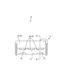
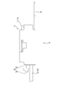
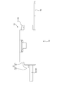
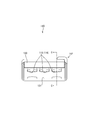
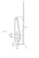
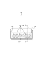
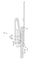
- the front view of the female terminal in Embodiment 1 Right side view of female terminal in FIG. AA sectional view of the female terminal in FIG.
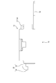
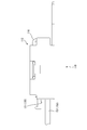
- the front view of the female terminal of the state which the male terminal in Embodiment 1 fitted 4 is a right side view of the female terminal before inserting the pressure increasing plate in FIG. BB sectional view of the female terminal before inserting the pressure intensifying plate in FIG. 4 is a right side view of the female terminal after insertion of the pressure increasing plate in FIG. BB cross-sectional view of the female terminal after insertion of the pressure increasing plate in FIG.
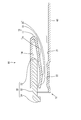
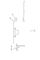
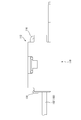
- Front view of female terminal in embodiment 2 Right side view of female terminal in FIG. CC sectional view of the female terminal in FIG.
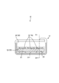
- FIG. 12 is a right side view of the female terminal before the pressure intensifying plate is inserted.
- DD sectional view of the female terminal before inserting the pressure intensifying plate in FIG. 12 is a right side view of the female terminal after the pressure intensifying plate is inserted in FIG.
- the female terminal 10 of Embodiment 1 is formed by punching and bending a copper sheet metal. Further, the processed female terminal 10 is plated with silver or the like. As shown in FIG. 3, the female terminal 10 includes a box-shaped female main body 12, a pressure increasing plate 30 inserted into the female main body 12, and an electric wire provided behind the female main body 12. The connection part 40 is provided. The female terminal 10 is fitted with the male terminal 50.
- the male terminal 50 is formed by punching and bending a sheet metal. Further, the processed male terminal 50 is plated with silver or the like. As shown in FIG. 6, the male terminal 50 has a male-side main body 52 having a plate shape.
- the female terminal 10 and the male terminal 50 are accommodated in a female housing and a male housing, respectively.
- the fitting direction of the female terminal 10 with the male terminal 50 is the front, and the direction from the bottom wall 21 of the female-side main body 12 toward the ceiling wall 14 is the upper side.
- the box-shaped female-side main body 12 opens in the front-rear direction.
- the ceiling wall 14 above the inside of the female main body 12 includes a contact pressure applying portion 16 that applies a contact pressure to the male main body 52.
- the contact pressure imparting portion 16 in the present embodiment is three contact pieces provided at equal intervals in a direction intersecting with the insertion direction of the male terminal 50 into the female-side main body portion 12. .
- the contact pressure applying portion 16 is integrated with the female-side main body portion 12.
- the contact pressure applying portion 16 is formed in a cantilever shape extending from the rear end portion of the ceiling wall 14 via a base end portion 17 continuous with the ceiling wall 14.
- the contact pressure imparting portion 16 includes a contact portion 18 that contacts the male main body portion 52, a base end portion 17 that continues to the ceiling wall 14, a rear inclined portion 19 that connects the contact portion 18 and the base end portion 17, and It has the front side inclination part 20 which inclines upward from the contact part 18 toward the front.
- the contact pressure applied by the contact pressure applying section 16 is slid between the contact 18 and the male main body 52, so that the female main body 12 and the male side
- the contact pressure is adjusted so that the plating applied to the main body 52 does not wear.
- the bottom wall 21 of the female main body 12 is provided with a bottom wall contact portion 22 that contacts the male main body 52.
- the bottom wall contact portion 22 is formed in a bead shape so as to protrude upward from the bottom wall 21 at positions corresponding to the contact portions 18 at both ends of the three contact portions 18. As shown in FIG. 3, it contacts the male main body 52.
- the pressure intensifying plate 30 includes a plate body portion 32 having a plate shape and a pressing portion 34.
- the pressure increasing plate 30 is made by punching and bending a metal plate, and is separate from the female-side main body 12.
- the pressing portion 34 is formed by bending the front end portion downward at a right angle.
- the end portion (end portion opposite to the pressing portion 34) 33 of the plate main body portion 32 is subjected to R processing.
- the pressure increasing plate 30 is inserted between the ceiling wall 14 inside the female-side main body 12 and the contact pressure applying portion 16. Further, the pressure increasing plate 30 is inserted into the female main body 12 until a position where the end 33 and the rear inclined portion 19 do not contact each other.
- the electric wire connecting portion 40 is formed to protrude rearward from the rear end of the bottom wall 21.
- An electric wire (not shown) is connected to the electric wire connecting portion 40, and the female terminal 10 and the electric wire are electrically connected.
- the male side main body 52 of the male terminal 50 is inserted into the female side main body 12 of the female terminal 10, and the male terminal 50 and the female terminal 10 are fitted.
- the male side main body 52 of the male terminal 50 slides on the contact portion 18 and the bottom wall contact portion 22 of the contact pressure applying portion 16 while the male terminal 50 is female. It is inserted into the side main body 12.
- the contact pressure of the contact pressure applying portion 16 is adjusted to such a contact pressure that the plating is not worn, so that the plating applied to the inside of the male side main body portion 52 and the female side main body portion 12 is worn.
- the male-side main body 52 can be inserted into the female-side main body 12 without any problem. Moreover, terminal insertion workability
- operativity can be improved because the insertion force at the time of inserting the male terminal 50 in the inside of the female side main-body part 12 reduces.
- the contact portion 18 with the male main body portion 52 also swings.
- the contact pressure applying portion 16 has a high contact pressure on the male main body portion 52. Therefore, the electrical connection between the male terminal 50 and the female terminal 10 is maintained without interruption. In this way, it is possible to prevent poor connection between the male terminal 50 and the female terminal 10 due to the influence of vibration or the like.
- the pressure increasing plate 30 is pulled out.
- the contact pressure applying unit 16 is displaced toward the ceiling wall 14, and the contact pressure applied by the contact pressure applying unit 16 to the male main body 52 is reduced.
- the contact pressure applying portion 16 is not displaced toward the bottom wall 21 before the pressure intensifying plate 30 is inserted. Is inserted into the female main body 12 with a low contact pressure or no contact pressure. Therefore, when the male terminal 50 is inserted into the female-side main body 12, the male terminal 50 is prevented from sliding on the contact pressure applying portion 16 to wear the plating applied to the male terminal 50 and the female terminal 10. be able to. Moreover, workability of terminal insertion can be improved by reducing the insertion force when the male terminal 50 is inserted into the female main body 12.
- the contact applying portion 16 is displaced toward the bottom wall 21 and the male terminal 50 is inserted.
- the contact pressure applied to can be made high. Therefore, it is possible to prevent a connection failure between the male terminal 50 and the female terminal 10 due to vibration or the like.
- the pressure increasing plate 30 is moved from between the ceiling wall 14 of the female-side main body 12 and the contact pressure applying portion 16 before the male terminal 50 starts to be detached.
- the contact pressure applied to the male terminal 50 is in a low or no contact pressure state, and when the male terminal 50 is detached, the male terminal 50 slides on the contact pressure applying portion 16 and the male terminal 50 and It is possible to prevent the plating applied to the female terminal 10 from being worn.
- the pressure increasing plate 30 is inserted from the front, the pressure increasing plate 30 is inserted following the operation of fitting the male housing holding the male terminal 50 into the female housing holding the female terminal 10. be able to. Further, since the female main body 12 and the contact pressure applying portion 16 are integrated, the cost of the female terminal 10 can be reduced.
- the end 33 of the pressure-increasing plate 30 hits the rear inclined portion 19 of the pressure-applying portion 16 to push down the pressure-applying portion 16 toward the bottom wall 21.
- the contact part 18 can be displaced to the bottom wall 21 side, and the contact pressure given to the male terminal 50 can be made into a high state.
- the pressure increasing plate 130 of the second embodiment includes a tapered portion 131 that is processed into a tapered shape so as to be tapered in the insertion direction.
- the pressure intensifying plate 130 is inserted into the inside of the contact pressure applying unit 116 to a position where the contact pressure applying unit 116 is not displaced toward the bottom wall 121 side.
- Other parts are the same as those in the first embodiment, and thus the description thereof is omitted.
- the male main body 152 of the male terminal 150 is inserted into the female main body 112 of the female terminal 110.
- the pressure intensifying plate 130 is pushed in the insertion direction of the male main body 152.
- the pressure application portion 116 is displaced toward the bottom wall 121 while the tapered portion 131 of the pressure increasing plate 130 slides on the front end portion of the front inclined portion 120 of the pressure application portion 116.
- the contact pressure applied to the male main body 152 by the contact portion 118 of the contact pressure applying portion 116 is increased.
- the tapered portion 131 of the contact pressure applying portion 116 hits the tip of the front inclined portion 120 of the contact pressure applying portion 116 and pushes the contact pressure applying portion 116 toward the bottom wall 121, thereby The contact pressure applied to the male terminal 150 by displacing the portion 118 toward the bottom wall 121 can be increased.
- the shape of the pressure increasing plate 30 is a plate shape. However, by inserting the pressure increasing plate 30 between the ceiling wall 14 and the contact pressure applying portion 16, the contact pressure applying portion 16 is made to be a bottom wall. Any shape can be used as long as it can be displaced to the 21 side.
- the shape of the pressure increasing plate may be a rod shape, or the end of the pressure increasing plate may be spherical.
- the contact pressure applying portion 16 is integrated with the female main body portion 12, but may be a separate body.
- the contact pressure imparting portion 16 extends forward from the rear end portion of the ceiling wall 14 of the female-side main body portion 12 and is formed in a cantilever shape. Anything can be used as long as the contact pressure is applied by contact from the side.
- the contact pressure applying portion may be formed in a cantilever shape extending rearward from the front end portion of the ceiling wall of the female-side main body portion.
- the pressure intensifying plate may be inserted into the female main body from the rear.
- the contact pressure of the contact pressure applying unit 16 before insertion of the pressure increasing plate 30 is set to such a degree that the terminal plating is not worn. However, the contact pressure may not be applied.
- SYMBOLS 10 Female terminal 12 ... Female side main-body part 14 ... Ceiling wall 16 ... Contact-pressure provision part 17 ... Base end part 18 ... Contact part 19 ... Rear side inclination part 20 ... Front side inclination part 21 ... Bottom wall 22 ... Bottom wall contact part DESCRIPTION OF SYMBOLS 30 ... Booster plate 32 ... Plate main-body part 33 ... End part 34 ... Pushing part 40 ... Electric wire connection part 50 ... Male terminal 52 ... Male side main body part 110 ... Female terminal 112 ... Female side main body part 116 ... Contact pressure provision part 118 ... Contact part 120 ... Front side inclined part 121 ... Bottom wall 130 ... Pressurizing plate 131 ... Taper part 150 ... Male terminal 152 ... Male side body part
Landscapes
- Connector Housings Or Holding Contact Members (AREA)
- Coupling Device And Connection With Printed Circuit (AREA)
- Manufacturing Of Electrical Connectors (AREA)
Priority Applications (2)
| Application Number | Priority Date | Filing Date | Title |
|---|---|---|---|
| US16/604,679 US10985486B2 (en) | 2017-04-13 | 2018-04-09 | Female terminal |
| CN201880023785.0A CN110521065B (zh) | 2017-04-13 | 2018-04-09 | 阴端子 |
Applications Claiming Priority (2)
| Application Number | Priority Date | Filing Date | Title |
|---|---|---|---|
| JP2017079809A JP6801563B2 (ja) | 2017-04-13 | 2017-04-13 | 雌端子 |
| JP2017-079809 | 2017-04-13 |
Publications (1)
| Publication Number | Publication Date |
|---|---|
| WO2018190286A1 true WO2018190286A1 (ja) | 2018-10-18 |
Family
ID=63793470
Family Applications (1)
| Application Number | Title | Priority Date | Filing Date |
|---|---|---|---|
| PCT/JP2018/014865 Ceased WO2018190286A1 (ja) | 2017-04-13 | 2018-04-09 | 雌端子 |
Country Status (4)
| Country | Link |
|---|---|
| US (1) | US10985486B2 (enExample) |
| JP (1) | JP6801563B2 (enExample) |
| CN (1) | CN110521065B (enExample) |
| WO (1) | WO2018190286A1 (enExample) |
Families Citing this family (1)
| Publication number | Priority date | Publication date | Assignee | Title |
|---|---|---|---|---|
| JP7123213B1 (ja) | 2021-04-21 | 2022-08-22 | 三菱電機株式会社 | 基板実装コネクタ |
Citations (8)
| Publication number | Priority date | Publication date | Assignee | Title |
|---|---|---|---|---|
| JPH0461882U (enExample) * | 1990-10-05 | 1992-05-27 | ||
| JP2000164271A (ja) * | 1998-11-27 | 2000-06-16 | Kel Corp | Icカード用コネクタ |
| JP2000357552A (ja) * | 1999-06-15 | 2000-12-26 | Sumitomo Wiring Syst Ltd | コネクタ装置及び多極コネクタ装置 |
| JP2006216433A (ja) * | 2005-02-04 | 2006-08-17 | Yazaki Corp | コネクタ |
| JP2011119105A (ja) * | 2009-12-02 | 2011-06-16 | Sumitomo Wiring Syst Ltd | 端子金具の接続構造 |
| JP2011129271A (ja) * | 2009-12-15 | 2011-06-30 | Sumitomo Wiring Syst Ltd | 端子金具 |
| JP2015005430A (ja) * | 2013-06-21 | 2015-01-08 | 株式会社日本自動車部品総合研究所 | コネクタ構造 |
| JP2017062913A (ja) * | 2015-09-24 | 2017-03-30 | 株式会社オートネットワーク技術研究所 | 端子の接続構造およびコネクタ装置 |
Family Cites Families (16)
| Publication number | Priority date | Publication date | Assignee | Title |
|---|---|---|---|---|
| US1536688A (en) * | 1924-03-29 | 1925-05-05 | Ivyal R Osborn | Electric flatiron connection |
| US3475717A (en) * | 1967-03-31 | 1969-10-28 | Itt | Zero force connector |
| US3643202A (en) * | 1970-03-06 | 1972-02-15 | James A Coon | Quick release female plug |
| US4357066A (en) * | 1980-05-27 | 1982-11-02 | Ford Motor Company | Printed circuit board edge terminal |
| US4684194A (en) * | 1984-07-16 | 1987-08-04 | Trw Inc. | Zero insertion force connector |
| JP2759160B2 (ja) | 1990-06-30 | 1998-05-28 | 株式会社タチエス | 車両用シートの組立方法 |
| US5897405A (en) * | 1997-05-29 | 1999-04-27 | Endo; Hiroshi | Electrical socket contact |
| JP4600874B2 (ja) * | 1998-09-11 | 2010-12-22 | 日本圧着端子製造株式会社 | コネクタの端子及びコネクタ |
| JP2000260521A (ja) * | 1999-03-09 | 2000-09-22 | Yazaki Corp | コネクタ |
| JP2001250623A (ja) * | 2000-03-03 | 2001-09-14 | Auto Network Gijutsu Kenkyusho:Kk | 端子構造 |
| DE10352069B9 (de) * | 2002-11-22 | 2013-05-29 | Tyco Electronics Amp Gmbh | Steckkontaktanordnung |
| JP4483601B2 (ja) * | 2005-01-28 | 2010-06-16 | 住友電装株式会社 | 雌端子金具 |
| DE102012002145A1 (de) * | 2012-02-04 | 2013-08-08 | Kostal Kontakt Systeme Gmbh | Hülsenkontakt für einen elektrischen Nullkraftsteckverbinder |
| JP6124537B2 (ja) * | 2012-09-03 | 2017-05-10 | 矢崎総業株式会社 | メス端子 |
| JP2014053205A (ja) | 2012-09-07 | 2014-03-20 | Yazaki Corp | メス端子、及び、それを用いたコネクタ |
| DE102015104377B4 (de) * | 2015-03-24 | 2020-04-02 | Lisa Dräxlmaier GmbH | Kontaktteil und Verfahren zum Herstellen eines Kontaktteils |
-
2017
- 2017-04-13 JP JP2017079809A patent/JP6801563B2/ja active Active
-
2018
- 2018-04-09 US US16/604,679 patent/US10985486B2/en active Active
- 2018-04-09 CN CN201880023785.0A patent/CN110521065B/zh active Active
- 2018-04-09 WO PCT/JP2018/014865 patent/WO2018190286A1/ja not_active Ceased
Patent Citations (8)
| Publication number | Priority date | Publication date | Assignee | Title |
|---|---|---|---|---|
| JPH0461882U (enExample) * | 1990-10-05 | 1992-05-27 | ||
| JP2000164271A (ja) * | 1998-11-27 | 2000-06-16 | Kel Corp | Icカード用コネクタ |
| JP2000357552A (ja) * | 1999-06-15 | 2000-12-26 | Sumitomo Wiring Syst Ltd | コネクタ装置及び多極コネクタ装置 |
| JP2006216433A (ja) * | 2005-02-04 | 2006-08-17 | Yazaki Corp | コネクタ |
| JP2011119105A (ja) * | 2009-12-02 | 2011-06-16 | Sumitomo Wiring Syst Ltd | 端子金具の接続構造 |
| JP2011129271A (ja) * | 2009-12-15 | 2011-06-30 | Sumitomo Wiring Syst Ltd | 端子金具 |
| JP2015005430A (ja) * | 2013-06-21 | 2015-01-08 | 株式会社日本自動車部品総合研究所 | コネクタ構造 |
| JP2017062913A (ja) * | 2015-09-24 | 2017-03-30 | 株式会社オートネットワーク技術研究所 | 端子の接続構造およびコネクタ装置 |
Also Published As
| Publication number | Publication date |
|---|---|
| JP6801563B2 (ja) | 2020-12-16 |
| CN110521065B (zh) | 2021-02-26 |
| US20200161786A1 (en) | 2020-05-21 |
| CN110521065A (zh) | 2019-11-29 |
| JP2018181612A (ja) | 2018-11-15 |
| US10985486B2 (en) | 2021-04-20 |
Similar Documents
| Publication | Publication Date | Title |
|---|---|---|
| JP4191725B2 (ja) | コネクタ装置 | |
| US20160020528A1 (en) | Female electrical contact part and method of forming same | |
| JP2010049896A (ja) | コネクタ | |
| EP3208888B1 (en) | Female terminal and female terminal production method | |
| EP2375512B1 (en) | Terminal fitting and production method therefor | |
| US11217925B2 (en) | Female terminal | |
| CN111194512B (zh) | 电线保持部件 | |
| JP6807024B2 (ja) | 雌端子 | |
| US9559460B2 (en) | Lever-type connector with regulating protrusion on male housing that engages lever on female housing to achieve connection without inclination between male and female housings | |
| JP2011129271A (ja) | 端子金具 | |
| US10367289B2 (en) | Terminal connecting structure and connector device | |
| WO2018190286A1 (ja) | 雌端子 | |
| CN113678320B (zh) | 端子及带端子电线 | |
| WO2021039359A1 (ja) | 端子、および端子付き電線 | |
| JP3874346B2 (ja) | 低挿入力メス側導体端子 | |
| CN103022779B (zh) | 连接器 | |
| JP2013258067A (ja) | コネクタ | |
| US9825376B2 (en) | Pressure welding contact having a bellows type terminal and pressure welding connector | |
| JP2011119108A (ja) | 雌端子金具 | |
| JP6270156B2 (ja) | コネクタ | |
| JP2020135998A (ja) | コネクタ | |
| JP6472337B2 (ja) | 電気コネクタ組立体および基板コネクタ | |
| JP2003036943A (ja) | コネクタ | |
| WO2023112109A1 (ja) | 端子金具 | |
| JP2007149383A (ja) | ファストン端子 |
Legal Events
| Date | Code | Title | Description |
|---|---|---|---|
| 121 | Ep: the epo has been informed by wipo that ep was designated in this application |
Ref document number: 18783831 Country of ref document: EP Kind code of ref document: A1 |
|
| NENP | Non-entry into the national phase |
Ref country code: DE |
|
| 122 | Ep: pct application non-entry in european phase |
Ref document number: 18783831 Country of ref document: EP Kind code of ref document: A1 |