WO2018179692A1 - トイレシステム - Google Patents
トイレシステム Download PDFInfo
- Publication number
- WO2018179692A1 WO2018179692A1 PCT/JP2018/001282 JP2018001282W WO2018179692A1 WO 2018179692 A1 WO2018179692 A1 WO 2018179692A1 JP 2018001282 W JP2018001282 W JP 2018001282W WO 2018179692 A1 WO2018179692 A1 WO 2018179692A1
- Authority
- WO
- WIPO (PCT)
- Prior art keywords
- toilet
- state
- room
- determined
- sensor
- Prior art date
- Legal status (The legal status is an assumption and is not a legal conclusion. Google has not performed a legal analysis and makes no representation as to the accuracy of the status listed.)
- Ceased
Links
Images







Classifications
-
- A—HUMAN NECESSITIES
- A47—FURNITURE; DOMESTIC ARTICLES OR APPLIANCES; COFFEE MILLS; SPICE MILLS; SUCTION CLEANERS IN GENERAL
- A47K—SANITARY EQUIPMENT; ACCESSORIES THEREFOR, e.g. TOILET ACCESSORIES
- A47K17/00—Other sanitary equipment not covered by the other groups of this subclass ; Holders for toilet brushes
-
- E—FIXED CONSTRUCTIONS
- E03—WATER SUPPLY; SEWERAGE
- E03D—WATER-CLOSETS OR URINALS WITH FLUSHING DEVICES; FLUSHING VALVES THEREFOR
- E03D9/00—Sanitary or other accessories for lavatories ; Devices for cleaning or disinfecting the toilet room or the toilet bowl; Devices for eliminating smells
-
- E—FIXED CONSTRUCTIONS
- E03—WATER SUPPLY; SEWERAGE
- E03D—WATER-CLOSETS OR URINALS WITH FLUSHING DEVICES; FLUSHING VALVES THEREFOR
- E03D1/00—Water flushing devices with cisterns ; Setting up a range of flushing devices or water-closets; Combinations of several flushing devices
-
- E—FIXED CONSTRUCTIONS
- E03—WATER SUPPLY; SEWERAGE
- E03D—WATER-CLOSETS OR URINALS WITH FLUSHING DEVICES; FLUSHING VALVES THEREFOR
- E03D2201/00—Details and methods of use for water closets and urinals not otherwise provided for
Definitions
- the present invention relates to a toilet system.
- Patent Document 1 discloses a conventional toilet system.
- This toilet system includes a camera or an ultrasonic sensor as a detection unit, and a control unit.
- the toilet system detects the state of the toilet with a camera or an ultrasonic sensor, and based on this, the control unit determines the state of use of the toilet and outputs a determination result.
- the determination result output from the control unit is displayed on the display.
- the present invention has been made in view of the above-described conventional situation, and it is an object to be solved to provide a toilet system capable of notifying a more detailed use state of the toilet.
- the toilet system of the present invention is A detection unit for detecting the situation in the toilet room; Based on the detection result of the detection unit, it is determined that the toilet room is empty and in use, and the toilet room is in a state immediately after the start of use in the state of use, Alternatively, a control unit that performs at least one determination that the toilet private room is in a state immediately before the end of use, and outputs a signal including the determined results; It is characterized by providing.
- This toilet system detects the situation in the toilet room, and is in a state immediately after the start of use or a state immediately before the end of use as another state of the two types of state of being empty and in use. At least one is determined, and a signal including the determination result is output. In this way, the toilet system of the present invention can inform the outside whether or not the toilet private room will soon be vacant.
- the toilet system of the present invention can inform the use state of the toilet in more detail.
- output a signal including a determination result notifies the determination result, such as a display board, a smart phone, a display device such as a display, a sound output device such as a speaker, etc. It is intended to output a signal (information signal) for informing the notification means.
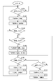
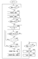
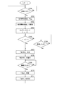
- FIG. 1 shows typically the toilet system which concerns on an Example. It is a flowchart (flow chart) which shows the flow of a process of the toilet system which concerns on Example 1.
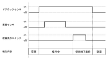
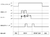
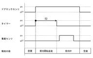
- FIG. It is a time chart which shows the relationship between the detection signal of the toilet system which concerns on Example 1, and alerting
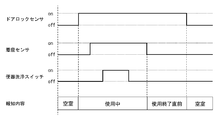
- FIG. It is a time chart (the 1) which shows the relationship between the detection signal of the toilet system which concerns on Example 2, and alerting
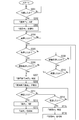
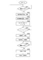
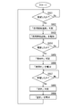
- FIG. 1 It is a flowchart which shows the flow of a process of the toilet system which concerns on Example 3. It is a time chart which shows the relationship between the detection signal of the toilet system which concerns on Example 3, and alerting
- the control unit determines that the toilet private room has changed from a state immediately after the start of use to a state in use based on a change in the detection result of the detection unit, or the toilet private room At least one of the determination that the state in use has changed to the state immediately before the end of use can be performed. In this case, it is possible to more accurately inform the outside of whether or not the toilet private room is about to become available.
- the control unit determines that the toilet private room is in a state immediately before the end of use
- the toilet private room is immediately before the end of use only when a plurality of predetermined conditions are satisfied. It can be determined that the state is.
- a plurality of conditions are set in advance to exclude a determination that cannot be made normally, such as not determining that the toilet room is in a state immediately before the end of use for 10 seconds from the start of use. Therefore, it is possible to prevent erroneous determination. As a result, it is possible to more accurately inform the outside whether or not the toilet private room is about to become available.
- the control unit can determine that the state has changed to a state in use when the detection unit detects a predetermined situation after determining that the toilet private room is in a state immediately before the end of use. In this case, even after notifying that the state is immediately before the end of use, the situation in the toilet room can be monitored, and the contents of the notice can be returned to being used according to the situation. For this reason, it is possible to more accurately notify the outside of whether or not the toilet private room is about to become available.
- the toilet system of Examples 1 to 7 is provided in the toilet facility 1 shown in FIG.
- the toilet facility 1 includes a door 2 at the entrance, a shared space 3 inside the door 2, a wash basin 4 disposed in the shared space 3, and a shared space (space) 3 provided in a partitioned manner. (Three in FIG. 1) toilet rooms 10.
- Each toilet private room 10 is provided with a door 11, a toilet device 12, a paper holder 13, and a remote controller 14.
- the door 11 is a door for entering and exiting each toilet private room 10.
- the toilet device 12 is a toilet device with a toilet seat device having a hot water washing function.
- the paper holder 13 holds roll paper (roll paper) rotatably.
- the remote controller 14 is provided with various switches (switches) for operating the toilet device 12 such as opening / closing the toilet seat and toilet lid, local cleaning, toilet cleaning and the like.
- Each toilet room 10 is provided with a door lock sensor 21, a seating sensor 22, a rotation sensor 23, and a toilet bowl washing switch 24 as detection units for detecting the situation in the toilet room 10.
- the door lock sensor 21 detects whether or not the door 11 is locked.
- the seating sensor 22 detects whether a user is seated on the toilet seat of the toilet device 12.
- the rotation sensor 23 detects whether or not the roll paper is rotating.
- the toilet cleaning switch 24 is a switch for performing toilet cleaning, and is provided in the remote controller 14.
- the door lock sensor 21, the seating sensor 22, the rotation sensor 23, and the toilet bowl washing switch 24 are connected to the control unit 30 and controlled by the control unit 30. Further, detection results by the door lock sensor 21, the seating sensor 22, the rotation sensor 23, and the toilet bowl cleaning switch 24 are transmitted to the control unit 30.
- the control part 30 determines the use state of the toilet private room 10 based on these detection results.
- the determination result by the control unit 30 is notified by the notification unit 40.
- reporting part 40 is a display which displays the determination result of the control part 30 by a character and a figure.
- the notification unit 40 is disposed on the outer wall of the toilet facility 1.
- some of the above operations are performed in any order before and after defecation, depending on the user.
- locking, undressing, sitting, etc. are operations before defecation
- local cleaning, local wiping, toilet bowl cleaning, sitting, dressing, unlocking, etc. are operations after defecation.
- the operation before defecation is an operation that is performed at a relatively early stage after entering the toilet private room prior to other actions, and the operation after defecation is performed at a relatively late stage before entering the toilet private room and before leaving. This is the action to be performed.
- attention is paid to one or more of these operations before and after defecation.
- the toilet system according to the first embodiment includes a door lock sensor 21 and a seating sensor 22 as detection units, and a control unit 30.
- This toilet system detects the situation in the toilet room 10 by detecting whether the door lock sensor 21 is locked and whether the seat sensor 22 is seated.
- the control part 30 determines the use condition of the toilet private room 10 based on these detection results. Further, the control unit 30 outputs a signal including the determination result. In the case of the present embodiment, the output signal is transmitted to the notification unit 40.
- step S101 it is determined in step S101 whether or not the door 11 is locked.
- the door lock sensor 21 determines whether or not the door 11 is locked.
- step S101 when it is determined that the door 11 is locked (the door lock sensor 21 is on), the control unit 30 determines that the toilet private room 10 is in use (step S102). And the alerting
- the toilet private room 10 is in an empty state when it is detected that the door 11 is not locked, that is, when the door lock sensor 21 is in an off state.
- This “vacant” state is a state in which there is no user in the toilet private room 10.
- whether the toilet room 10 is in use is determined by the state in which it is detected that the door 11 is locked, that is, by the door lock sensor 21 being in the on state.
- This “in use” state is a state in which a user has entered the toilet private room 10.
- step S104 it is determined whether or not the user of the toilet private room 10 is seated on the toilet seat of the toilet device 12.
- the seat sensor 22 determines whether or not the user is seated. That is, when the seating sensor 22 is on, it is determined that it is seated, and when it is off, it is determined that it is not seated. If it is determined that the seating sensor 22 is on, the process proceeds to step S105.
- step S ⁇ b> 105 it is determined whether or not the user of the toilet room 10 has left the toilet device 12, that is, whether or not the seating sensor 22 in the on state has been turned off.
- the control unit 30 determines that the toilet private room 10 is in a state immediately before the end of use when it is determined that the user has left the room. In other words, the determination “just before the end of use” in the first embodiment is made based on the determination that the user is away.
- step S105 When it is determined in step S105 that the user has been seated away (the seating sensor 22 is off), the control unit 30 determines that the toilet room 10 is in a state immediately before the end of use (step S106). The determination result is output to the notification unit 40. And the alerting
- step S108 it is determined whether or not the door 11 is unlocked.
- the control unit 30 determines that the toilet private room 10 is empty (step S109), and the notification unit 40 notifies the fact. (Step S110). That is, as shown in FIG. 3, when the door lock sensor 21 is switched from on to off, the notification content of the notification unit 40 is switched from “immediately before use” to “empty”.
- step S111 determines whether or not the user of the toilet cubicle 10 is seated on the toilet seat of the toilet device 12 again. Judging. This assumes the case where the user of the toilet private room 10 is seated again, for example, by making a bowel movement again before unlocking. In this case, assuming that the private toilet room 10 will soon be no longer empty, the notification content “just before use” is returned to “in use” again. Specifically, when it is determined again in step S111 that the seating sensor 22 is on, the control unit 30 determines in step S112 that it is in use.
- the notification unit 40 notifies “in use” again in step S113, and returns to step S105.
- the seating sensor 22 as the detection unit detects the seating as a predetermined situation.
- the unit 30 determines that the toilet room 10 has changed from a state immediately before the end of use to a state in use.
- the toilet system of Example 1 determines that the toilet room 10 is in a state immediately before the end of use in subsequent processing only when locking as a plurality of predetermined conditions and sitting after locking are detected. .
- the toilet system of Example 1 is the door lock sensor 21 and the seating sensor 22 as a detection part which each detects the presence or absence of locking as a situation in the toilet private room 10, and the presence or absence of seating, and the door lock sensor 21 and seating. Based on the detection result of the sensor 22, it is determined that the toilet room 10 is empty and in use, and the determination that the toilet room 10 is in a state immediately before use is completed in the state of use. And a control unit 30 that outputs a signal including the determination results.
- the toilet system of the first embodiment when detecting the situation in the toilet room 10, the presence or absence of locking by the door lock sensor 21 and the presence or absence of the seating by the seating sensor 22 are detected. As another state of the type, it is determined that the state is just before the end of use, and a signal including the determination result is output. As described above, the toilet system according to the first embodiment can notify the outside whether or not the toilet private room is about to become available.
- the toilet system can inform the use state of the toilet in more detail.
- control unit 30 determines that the toilet private room 10 has changed from a state in use to a state immediately before use based on a change in the detection result of the seating sensor 22 as a detection unit. For this reason, it is possible to more accurately notify the outside of whether or not the toilet private room is about to become available.
- control unit 30 determines that the toilet room 10 is in a state immediately before the end of use, only when the toilet room 10 detects locking and seating after locking as a predetermined plurality of conditions, It is determined that the state is just before the end of use. Thereby, it is possible to prevent erroneous determination. As a result, it is possible to more accurately inform the outside whether or not the toilet private room is about to become available.
- control unit 30 determines that the toilet private room 10 is in a state immediately before the end of use
- the seating sensor 22 as the detection unit detects the seating as a predetermined situation
- the control unit 30 changes to the in-use state. judge.
- the toilet system according to the second embodiment is different from the first embodiment in that the toilet system includes a toilet cleaning switch 24 in addition to the door lock sensor 21 and the seating sensor 22 according to the first embodiment as a detection unit. That is, the toilet system according to the second embodiment detects the situation in the toilet room 10 by detecting whether the door lock sensor 21 is locked, whether the seat sensor 22 is seated, and whether the toilet cleaning switch 24 is operated. . Based on these detection results, the control unit 30 determines the usage state of the toilet room 10 and outputs a signal including the determination result. Note that the signal output from the control unit 30 is transmitted to the notification unit 40. The notification unit 40 that has received the signal notifies the determination result by the control unit 30.
- step S201 when it is determined in step S201 that the door 11 is locked and it is determined that the door 11 is locked (the door lock sensor 21 is on). Determines that the toilet room 10 is “in use” by the control unit 30 (step S202) and notifies the notification unit 40 (step S203). That is, as shown in FIGS. 5 and 6, when the door lock sensor 21 is switched from OFF to ON, the notification content of the notification unit 40 is switched from “empty” to “in use”.
- steps S201 to S203 are the same as steps S101 to S103 of the first embodiment.
- the determination that the control unit 30 is in a state immediately before the end of use is detected by the seating sensor 22 and the toilet cleaning switch 24 is operated. This is different from the control process of the first embodiment in that the process is performed when the error is detected.
- step S204 it is determined whether the user of the toilet room 10 is seated on the toilet seat of the toilet device 12, and if it is determined that the user is seated (the seat sensor 22 is on), The presence / absence of the seat is detected (steps S205 and S210) and the presence / absence of the toilet cleaning (steps S206 and S209).
- the toilet system according to the second embodiment is in a state immediately before the use of the toilet private room 10 only when the locking and the seating after the locking are detected as a plurality of predetermined conditions are satisfied. Make a decision. The determination that the toilet private room 10 is in a state immediately before the end of use is made by detecting the presence or absence of seating and the presence or absence of toilet cleaning.
- step S205 the presence / absence of the absence is detected. If it is determined in step S205 that he / she has been seated (the seating sensor 22 is off), then in step S206, it is determined whether the toilet bowl has been washed, that is, whether or not the toilet bowl washing switch 24 has been operated. To do. In other words, the determination as to whether or not the toilet bowl has been washed in step S206 is a determination made after leaving the seat. If it is determined that both the seating (the seating sensor 22 is off) and the toilet flushing (the toilet flushing switch 24 is on) are performed in this way, the control unit 30 determines that the toilet private room 10 is in a state just before the end of use. Determination is made (step S207).
- the determination result is output to the notification unit 40.
- reports "just before an end of use” as a determination result of the control part 30 (step S208). That is, as shown in FIG. 5, when the seating sensor 22 is switched from on to off first, and then the toilet flushing switch 24 is operated, the notification content of the notification unit 40 when the toilet flushing switch 24 is operated. Is switched from “in use” to “just before use”.
- step S205 determines whether or not the toilet bowl has been washed in the same manner as in step S206. The user at this time is in a seated state (a state before leaving). If it is determined in step S209 that the toilet bowl has been cleaned (the toilet bowl cleaning switch 24 is turned on), the process proceeds to step S210. If it is not determined that the toilet bowl has been cleaned, the process returns to step S205. If it is determined in step S209 that the toilet bowl has been washed, it is determined in step S210 whether the seat has been removed. If it is determined that the user has left, the process proceeds to step S207.
- the control unit 30 determines that the toilet room 10 is in a state immediately before the end of use. Determination is made (step S207). And the alerting
- the control unit 30 determines that the toilet private room 10 has changed from a state in use to a state immediately before the end of use based on a change in the detection result from on to off of the seating sensor 22 as the detection unit.
- the control process of the second embodiment since the determination based on the detection results of the two detection units that detect the presence / absence of the two operations of sitting and toilet flushing is performed, the user of the toilet private room 10 has left the seat. A process assuming two patterns (pattern) for performing toilet cleaning in a state and performing toilet cleaning in a non-seated state is performed. Further, the control unit 30 is based on the change in the detection result from the on state to the off state of the seating sensor 22 as the detection unit, and the change in the detection result from the off state to the on state of the toilet flushing switch 24. Thus, it is determined that the toilet private room 10 has changed from a state in use to a state immediately before the end of use.
- step S211 it is determined whether or not the door 11 has been unlocked. If it is determined that the door 11 has been unlocked, it is determined that the toilet private room 10 is “vacant” (step S212), and that is notified. (Step S213). If it is determined that the door 11 is not unlocked, the presence / absence of seating is determined again (step S214). If the seating is confirmed again, it is determined that the door 11 is in use (step S214). S215), “in use” is notified again (step S216). That is, as shown in FIGS. 5 and 6, when the door lock sensor 21 is switched from on to off, the notification content of the notification unit 40 is switched from “immediately before use” to “empty”.
- the toilet system includes the door lock sensor 21, the seating sensor 22, and the toilet bowl cleaning switch 24 as the detection unit that detects the situation in the toilet private room 10, the door lock sensor 21, the seating sensor 22, and the toilet bowl cleaning. Based on the detection result of the switch 24, it is determined that the toilet room 10 is empty and in use, and at the time of use, it is determined that the toilet room 10 is in a state immediately before the end of use. And a control unit 30 that outputs a signal including the determination results.
- the toilet system of Example 2 detects the presence or absence of locking by the door lock sensor 21, the presence or absence of the seating by the seating sensor 22, and the presence or absence of the operation of the toilet cleaning switch 24 when detecting the situation in the toilet private room 10.
- the empty state and the in-use state it is determined that the state is immediately before the end of use, and a signal including the determination result is output.
- the toilet system according to the second embodiment can notify the outside whether or not the toilet private room is about to become available.
- the toilet system according to the second embodiment can also notify a more detailed use state of the toilet.
- control unit 30 determines that the toilet room 10 has changed from a state in use to a state just before the end of use based on changes in detection results of the seating sensor 22 and the toilet bowl washing switch 24 as detection units. . For this reason, it is possible to more accurately notify the outside of whether or not the toilet private room is about to become available.
- control unit 30 determines that the toilet room 10 is in a state immediately before the end of use, only when the toilet room 10 detects locking and seating after locking as a predetermined plurality of conditions, It is determined that the state is just before the end of use. Thereby, it is possible to prevent erroneous determination. As a result, it is possible to more accurately inform the outside whether or not the toilet private room is about to become available.
- control unit 30 determines that the toilet private room 10 is in a state immediately before the end of use
- the seating sensor 22 as the detection unit detects the seating as a predetermined situation
- the control unit 30 changes to the in-use state. judge.
- control unit 30 determines, based on the detection results of the two detection units, the seating sensor 22 as the detection unit and the toilet bowl washing switch 24, that the toilet room 10 is in a state just before the end of use in the state of use. To do. For this reason, compared with the case where it determines based on the detection result of one detection part like Example 1, the information of whether a toilet private room is soon vacant can be notified outside. .
- the toilet system of Example 3 is different from Example 1 in that it has a rotation sensor 23 instead of the seating sensor 22 of Example 1 as a detection unit. That is, the toilet system according to the third embodiment detects the situation in the toilet room 10 by detecting whether the door lock sensor 21 is locked and whether the rotation sensor 23 is rotating the roll paper. Based on these detection results, the control unit 30 determines the usage state of the toilet room 10 and outputs a signal including the determination result. Note that the signal output from the control unit 30 is transmitted to the notification unit 40. The notification unit 40 that has received the signal notifies the determination result by the control unit 30.
- the door lock sensor 21 detects whether or not the door 11 is locked in step S301, and the door 11 is locked (the door lock sensor 21 is turned on). If it is determined, the control unit 30 determines that the toilet private room 10 is “in use” (step S302), and notifies the notification unit 40 (step S303). That is, as shown in FIG. 8, when the door lock sensor 21 is switched from OFF to ON, the notification content of the notification unit 40 is switched from “empty” to “in use”.
- steps S301 to S303 are the same as steps S101 to S103 of the first embodiment.
- the determination that the control unit 30 is in a state immediately before the end of use is based on the determination whether the user of the toilet room 10 is winding the roll paper. Based on. Specifically, the presence or absence of rotation caused by winding the roll paper by the rotation sensor 23 is detected. When winding is detected, a timer is started, and a state immediately before the end of use after a predetermined time has elapsed. Judgment is made.
- step S304 it is determined whether the user of the toilet room 10 is winding the roll paper. If it is determined that the roll paper is being wound (rotation sensor 23 is on). Then, a timer for a predetermined time T1 is started (step S305). When the timer is started, it is determined in step S306 whether or not winding is stopped. If it is determined in step S306 that winding is stopped (rotation sensor 23 is off), the process proceeds to step S307, and waits for completion of countdown by the timer. While the countdown by the timer continues, the process returns to step S306, and the detection of whether or not the roll paper is wound is continuously performed.
- step S306 If it is determined in step S306 that winding is not stopped (rotation sensor 23 is on) during countdown by the timer, the process returns to step S305, the timer is reset and restarted. This assumes that the roll paper is wound a plurality of times in one stool. For this reason, as shown in FIG. 8, when it is detected that the roll paper has been taken up again during the countdown by the timer, the countdown by the timer by the detection of the previous winding is invalidated, and the predetermined time is again set. The timer starts from time T1.
- step S307 If it is determined in step S307 that the timer countdown has ended, the control unit 30 determines that the toilet room 10 is in a state immediately before the end of use (step S308). The determination result is output to the notification unit 40. And the alerting
- control unit 30 starts the timer based on the change in the detection result from the on state to the off state of the rotation sensor 23 as the detection unit, and the countdown of the timer ends, whereby the toilet private room 10 is determined to have changed from a state in use to a state immediately before the end of use.
- step S310 it is determined whether or not the door 11 is unlocked. If it is determined that the door 11 is unlocked, it is determined that the toilet private room 10 is “vacant” (step S311), and a notification to that effect is given. (Step S312). That is, as shown in FIG. 8, when the door lock sensor 21 is switched from on to off, the notification content of the notification unit 40 is switched from “immediately before use” to “empty”.
- the toilet system according to the third embodiment is based on the detection results of the door lock sensor 21 and the rotation sensor 23 and the detection results of the door lock sensor 21 and the rotation sensor 23 as detection units for detecting the situation in the toilet private room 10. It is determined that the private room 10 is in an empty state and in use, and it is determined that the toilet private room 10 is in a state immediately before the end of use in the state of use, and a signal including the results of these determinations is provided. And a control unit 30 for outputting.
- the toilet system of the third embodiment when detecting the situation inside the toilet room 10, the presence or absence of locking by the door lock sensor 21 and the presence or absence of winding of the roll paper by the rotation sensor 23 are detected. As other states of the two types of states, it is determined that the state is immediately before the end of use, and a signal including the determination result is output. As described above, the toilet system according to the third embodiment can inform the outside whether or not the toilet private room is about to become available.
- the toilet system according to the third embodiment can also inform the use state of the toilet in more detail.
- control part 30 starts a timer based on the change of the detection result of the rotation sensor 23 as a detection part, and when this timer ends countdown, the state immediately before the end of use from the state in which the toilet private room 10 is in use. It is determined that it has changed to. For this reason, it is possible to more accurately notify the outside of whether or not the toilet private room is about to become available.
- the toilet system of Example 4 has a toilet flushing switch 24 as a detection unit in addition to the door lock sensor 21 and the rotation sensor 23 of Example 3. That is, the toilet system according to the fourth embodiment detects the situation in the toilet room 10 by detecting whether the door lock sensor 21 is locked, whether the rotation sensor 23 is rotating, and whether the toilet cleaning switch 24 is operated. To do. Specifically, the control unit 30 determines the usage state of the toilet private room 10 based on these detection results, and outputs a signal including the determination result. Note that the signal output from the control unit 30 is transmitted to the notification unit 40. The notification unit 40 that has received the signal notifies the determination result by the control unit 30.
- step S401 when the door lock sensor 21 detects whether or not the door 11 is locked in step S401, the door 11 is locked (the door lock sensor 21 is turned on).
- the control unit 30 determines that the toilet private room 10 is “in use” (step S402), and the notification unit 40 notifies (step S403). That is, as shown in FIG. 10, when the door lock sensor 21 is switched from OFF to ON, the notification content of the notification unit 40 is switched from “empty” to “in use”.
- steps S401 to S403 are the same as steps S101 to S103 of the first embodiment.
- step S404 it is determined whether or not the user of the toilet private room 10 is winding the roll paper. If it is determined that the roll paper is being wound (rotation sensor 23 is on), the predetermined time T1 is set. A timer is started (step S405). When the timer is started, it is determined whether or not the winding is stopped (step S406). If it is determined in step S406 that winding is stopped (the rotation sensor 23 is off), the process proceeds to step S407, and waits for completion of countdown by the timer. Further, while the countdown by the timer continues, the process returns to step S406, and the detection of whether or not the roll paper is wound is continuously performed.
- step S406 If it is determined in step S406 that winding is not stopped (rotation sensor 23 is on) during countdown by the timer, the process returns to step S405, and the timer is reset and restarted.
- steps S404 to S407 are also the same as steps S304 to S307 of the third embodiment.
- step S408 it is determined whether or not the toilet bowl has been washed, that is, whether or not the toilet bowl washing switch 24 has been operated is detected. If it is determined that the toilet bowl has been washed, the determination “just before the end of use” is performed (step S409), and the determination result is output to the notification unit 40. And the alerting
- the determination that the controller 30 is in a state immediately before the end of use is that the toilet flushing switch 24 is operated, that is, the toilet flushing switch 24 is turned on. This is done by being detected. However, as shown in FIG.
- the control unit 30 determines that the toilet private room 10 is in a state immediately before the end of use based on a change in the detection result of the toilet cleaning switch 24 serving as the detection unit from OFF to ON. I do.
- the control unit 30 detects that the winding is being performed when a plurality of predetermined conditions are satisfied, and only when the countdown of the timer that is started by detecting the winding is finished, the toilet private room 10 Is determined to be in a state immediately before the end of use.
- step S411 it is determined whether or not the door 11 is unlocked. If it is determined that the door 11 has been unlocked, it is determined that the toilet private room 10 is “empty” (step S412), and a notification to that effect is given. (Step S413). That is, as shown in FIG. 10, when the door lock sensor 21 is switched from on to off, the notification content of the notification unit 40 is switched from “immediately before use” to “empty”.
- the toilet system of Example 4 is the door lock sensor 21, the rotation sensor 23, and the toilet bowl washing switch 24 as a detection part which detects the condition in the toilet private room 10, and the door lock sensor 21, the rotation sensor 23, and the toilet bowl. Based on the detection result of the cleaning switch 24, it is determined that the toilet room 10 is empty and in use, and determination that the toilet room 10 is in a state immediately before use is completed in use. And a control unit 30 that outputs a signal including the determined results.
- the toilet system of the fourth embodiment when detecting the situation in the toilet private room 10, whether the door lock sensor 21 is locked, whether the rotation sensor 23 is wound up, and whether the toilet cleaning switch 24 is operated As a result of detection, it is determined that the state is immediately before the end of use as another state of the two types of states, ie, the empty state and the in-use state, and a signal including the determination result is output. As described above, the toilet system according to the fourth embodiment can notify the outside whether or not the toilet private room is about to become available.
- the toilet system according to the fourth embodiment can also inform a more detailed use state of the toilet.
- control unit 30 determines that the toilet private room 10 is in a state immediately before the end of use based on a change in the detection result from OFF to ON of the toilet cleaning switch 24 serving as a detection unit. For this reason, it is possible to more accurately notify the outside of whether or not the toilet private room is about to become available.
- control unit 30 determines that the toilet private room 10 is in a state immediately before the end of use
- the control unit 30 detects and winds up during winding (winding start) as if a plurality of predetermined conditions are satisfied. Only when the countdown of the timer that is started by detecting is finished, it is determined that the toilet room 10 is in a state immediately before the end of use. Thereby, it is possible to prevent erroneous determination. As a result, it is possible to more accurately inform the outside whether or not the toilet private room is about to become available.
- the toilet system of the fifth embodiment is different from the first to fourth embodiments in that the control unit 30 determines that the toilet private room 10 in use is in a state immediately after the start of use based on the detection result of the detection unit.
- the toilet system of Example 5 has a door lock sensor 21 as a detection unit.
- the control unit 30 determines the use state of the toilet room 10 based on the detection result of the detection unit, and outputs the determination result. Note that the signal output from the control unit 30 is transmitted to the notification unit 40.
- the notification unit 40 that has received the signal notifies the determination result by the control unit 30.
- the door lock sensor 21 detects whether or not the door 11 is locked in step S ⁇ b> 501. If it is determined in step S502 that the door 11 is locked (the door lock sensor 21 is on), the control unit 30 determines that the toilet room 10 is in a state immediately after the start of use (step S502). That is, when the on-state of the door lock sensor 21 is detected, the control unit 30 determines that the toilet room 10 is in a state immediately after the start of use in a state where the toilet room 10 is in use. The determination result is output to the notification unit 40.
- step S503 the alerting
- the door lock sensor 21 is switched from OFF to ON, the notification content of the notification unit 40 is switched from “vacant” to “immediately after the start of use”.
- step S504 a timer for a predetermined time T2 is started.
- step S505 the timer waits for the countdown to end.
- the control unit 30 determines that the toilet room 10 has changed from a state immediately after the start of use to a state in use (step S506), and notifies “in use” (step S507). That is, the control unit 30 determines that the toilet private room 10 is in use when a predetermined time T2 has elapsed since it was determined that the toilet private room 10 is immediately after the start of use.
- steps S508 to S510 is the same as that of steps S310 to S312 of the third embodiment. That is, in step S508, it is determined whether or not the door 11 is unlocked. If it is determined that the door 11 is unlocked, it is determined that the toilet private room 10 is “empty” (step S509).
- the notification unit 40 notifies “vacant” (step S510). That is, as shown in FIG. 12, when the door lock sensor 21 is switched from on to off, the notification content of the notification unit 40 is switched from “in use” to “empty”.
- the toilet system of Example 5 is in a state where the toilet private room 10 is empty based on the door lock sensor 21 as a detection unit for detecting the situation in the toilet private room 10 and the detection result of the door lock sensor 21.
- a control unit 30 that determines that the state is immediately after the start of use and outputs a signal including the determined results is provided.
- the toilet system of the fifth embodiment when detecting the situation in the toilet private room 10, the presence or absence of locking by the door lock sensor 21 is detected, and the other states of the two types of states, that is, the empty state and the in-use state, are detected. Then, it is determined that the state is immediately after the start of use, and a signal including the determination result is output. Thus, since the toilet system of Example 5 can notify that it is shortly after a toilet private room is started use, it can notify the exterior whether a toilet private room will be vacant soon.
- the toilet system according to the fifth embodiment can also inform a more detailed use state of the toilet.
- the toilet system of Example 5 since the toilet system of Example 5 has only the door lock sensor 21 which detects the presence or absence of locking of the door 11 as a detection part, it can be set as a simple structure.
- the control unit 30 determines that the toilet private room 10 in use is in a state immediately after the start of use based on the detection result of the detection unit.
- This embodiment differs from the fifth embodiment in that a seating sensor 22 is provided in addition to the door lock sensor 21.
- the toilet system according to the sixth embodiment detects the situation in the toilet room 10 by detecting whether the door lock sensor 21 is locked and detecting whether the seat sensor 22 is seated.
- the control unit 30 determines the use state of the toilet room 10 based on the detection results of these detection units, and outputs the determination result.
- step S601 when the door 11 is detected to be locked in step S601 and it is determined that the door 11 is locked (the door lock sensor 21 is on),
- the control unit 30 determines that the toilet room 10 is “immediately after the start of use” (step S602), outputs the determination result to the notification unit 40, and notifies the notification unit 40 (step S603). That is, as shown in FIG. 14, when the door lock sensor 21 is switched from OFF to ON, the notification content of the notification unit 40 is switched from “vacant” to “immediately after the start of use”.
- step S604 it is determined whether the user of the toilet private room 10 is seated on the toilet seat of the toilet device 12.
- the control unit 30 determines that the toilet private room 10 is “in use” (step S605), and the notification unit 40 determines that the toilet private room 10 is “ “Not in use” is notified (step S606). That is, as shown in FIG. 14, when the seating sensor 22 is switched from off to on, the notification content of the notification unit 40 is switched from “immediately after use” to “in use”.
- the toilet system of Example 6 it is determined that the toilet private room 10 is in a state immediately after the start of use by detecting the locking of the door 11, and the user is seated by detecting the seating of the user. Judge that it has changed.
- steps S607 to S609 is the same as steps S508 to S510 of the fifth embodiment. That is, in step S607, it is determined whether or not the door 11 is unlocked. If it is determined that the door 11 is unlocked, it is determined that the toilet private room 10 is “vacant” (step S608). The notification unit 40 notifies “vacant” (step S609). That is, as shown in FIG. 14, when the door lock sensor 21 is switched from on to off, the notification content of the notification unit 40 is switched from “in use” to “empty”.
- the toilet system of Example 6 is based on the detection result of the door lock sensor 21 and the seating sensor 22 as a detection part which detects the condition in the toilet private room 10, and these door lock sensors 21 and the seating sensor 22.
- As another state of the two types of states of the toilet private room 10 being empty and in use it is determined that it is in a state immediately after the start of use, and a control unit 30 that outputs a signal including the determination result I have.
- the toilet system of the sixth embodiment in detecting the situation inside the toilet room 10, the presence or absence of locking by the door lock sensor 21 and the presence or absence of the seating by the seating sensor 22 are detected. As another state of the type state, it is determined that the state is immediately after the start of use, and a signal including the determination result is output. As described above, the toilet system according to the sixth embodiment can inform the outside whether or not the toilet private room is about to become empty since the toilet private room can be notified immediately after the start of use. .
- the toilet system according to the sixth embodiment can also inform the use state of the toilet in more detail.
- the toilet system of Example 7 has the door lock sensor 21 and the seating sensor 22 as a detection part similarly to Example 6.
- FIG. The toilet system according to the seventh embodiment detects the situation in the toilet room 10 by detecting whether the door lock sensor 21 is locked and detecting whether the seat sensor 22 is seated.
- the control part 30 determines the use condition of the toilet private room 10 based on the detection result of a detection part, it differs from Example 6 by the point of the process at the time of making this determination. Specifically, in the toilet system of Example 7, the determination that the state immediately after the start of use has changed to the in-use state is either the end of countdown of the timer that is activated by detecting locking or the detection of sitting It is done by the earlier one.
- step S701 when it is determined that the door 11 is locked and the door 11 is locked (the door lock sensor 21 is on) in step S701,
- the control unit 30 determines that the toilet room 10 is “immediately after the start of use” (step S702), outputs the determination result to the notification unit 40, and notifies the notification unit 40 (step S703). That is, as shown in FIGS. 16 and 17, when the door lock sensor 21 is switched from OFF to ON, the notification content of the notification unit 40 is switched from “empty” to “immediately after the start of use”.
- step S704 a timer for a predetermined time T2 is started.
- step S705 it is determined whether countdown by the timer has been completed. If it is not determined that the process has been completed, the process proceeds to step S706, and the presence / absence of seating is detected by the seating sensor 22. If it is determined in step S705 that the timer countdown has ended, or if it is determined in step S706 that the user has been seated (the seating sensor 22 is on), in step S707, the controller 30 is in use.
- step S708 the notification unit 40 notifies this. That is, as shown in FIG. 16, the seating sensor 22 switches from off to on before the timer countdown ends, or as shown in FIG. 17, the timer countdown before the seating sensor 22 switches from off to on. By ending, the notification content of the notification unit 40 is switched from “immediately after use” to “in use”.
- steps S709 to S711 are the same as steps S508 to S510 of the fifth embodiment. That is, in step S709, it is determined whether or not the door 11 is unlocked. If it is determined that the door 11 is unlocked, it is determined that the toilet private room 10 is “vacant” (step S710). The notification unit 40 notifies “vacant” (step S711). That is, as shown in FIGS. 16 and 17, when the door lock sensor 21 is switched from on to off, the notification content of the notification unit 40 is switched from “in use” to “empty”.
- the toilet system of Example 7 is based on the detection result of the door lock sensor 21 and the seating sensor 22 as a detection part which detects the condition in the toilet private room 10, and these door lock sensors 21 and the seating sensor 22.
- a control unit 30 that determines whether the toilet private room 10 is in an empty state or is in use as a state immediately after the start of use as another state, and outputs a signal including the determined results. It is equipped with.
- the toilet system of the seventh embodiment when detecting the situation in the toilet room 10, the presence or absence of locking by the door lock sensor 21 and the presence or absence of the seating by the seating sensor 22 are detected. As another state of the type state, it is determined that the state is immediately after the start of use, and a signal including the determination result is output. As described above, the toilet system according to the fifth embodiment can inform the outside whether or not the toilet private room is almost empty since the toilet private room can be notified immediately after the start of use. .
- the toilet system according to the seventh embodiment can also notify a more detailed state of use of the toilet.
- the present invention is not limited to the examples described with reference to the above description and drawings.
- the following embodiments are also included in the technical scope of the present invention.
- the configuration including one notification unit that notifies the use status of a plurality of toilet private rooms is illustrated. However, in the embodiment including a plurality of notification units corresponding to each of the plurality of toilet private rooms. There may be.
- (3) in the first to seventh embodiments as the notification form of the notification unit, the form in which characters, figures, and the like are displayed on the display unit is illustrated. However, simple display such as simply displaying colors may be used. Good.
- the notification form is not limited to a form for notifying information on the use state of each toilet room, for example, the number of toilet rooms such as “vacant” and “in use” in the entire toilet facility, etc.
- Other notification forms may be used.
- the display unit provided on the outer wall of the toilet facility is illustrated as the notification unit. However, the display unit may be provided in a common space. Further, the notification unit may be configured to display remotely from the toilet facility using a display provided in a place separated from the toilet facility, a portable terminal such as a smartphone, or the like.
- the display unit is exemplified as the notification unit. However, the notification unit may be configured to notify by voice or the like.
- the detection unit includes a form having a door lock sensor, a seating sensor, a rotation sensor, a toilet bowl washing switch, etc., but the detection unit is not limited to these, for example, Open / close toilet seat (auxiliary toilet seat) and toilet lid, use of diaper changing table, seating of infant chair, local cleaning, water level change in toilet bowl due to defecation, toilet cleaning and local cleaning It is also possible to detect other movements such as a change in the water flow in the water supply pipe, clothing and undressing, and entering and leaving the room. Moreover, the detection method and detection means by a detection part are not specifically limited.
- the present invention is not limited to this.
- both of the state immediately before the start of use and the state immediately after the start of use such as a combination of any of the above-described Examples 1 to 4 and any of Examples 5 to 7
- the form to determine may be sufficient.
- a state other than the state immediately before the end of use and the state immediately after the start of use, or another state in addition to these may be determined.
- the timer is started by detecting the presence or absence of rotation caused by winding the roll paper by the rotation sensor, and when the countdown of this timer is completed, it is in a state immediately before the end of use.
Landscapes
- Health & Medical Sciences (AREA)
- Public Health (AREA)
- Epidemiology (AREA)
- General Health & Medical Sciences (AREA)
- Life Sciences & Earth Sciences (AREA)
- Engineering & Computer Science (AREA)
- Hydrology & Water Resources (AREA)
- Water Supply & Treatment (AREA)
- Toilet Supplies (AREA)
- Bidet-Like Cleaning Device And Other Flush Toilet Accessories (AREA)
- Sanitary Device For Flush Toilet (AREA)
Abstract
より詳細なトイレの使用状態を知らせることができるトイレシステムを提供する。 トイレシステムは、トイレ個室(10)内の状況を検知する検知部(ドアロックセンサ(21)、着座センサ(22)、回転センサ(23)、便器洗浄スイッチ(24)等)と、検知部の検知結果に基づいて、トイレ個室(10)が空きの状態、又は使用中の状態であることを判定するとともに、使用中の状態においてトイレ個室(10)が使用開始直後の状態であること、又はトイレ個室(10)が使用終了直前の状態であることの少なくとも一方の判定を行い、これら判定した結果を含む信号を出力する制御部(30)と、を備える。
Description
本発明は、トイレシステム(toilet system)に関するものである。
特許文献1は従来のトイレシステムを開示している。このトイレシステムは、検知部としてのカメラ(camera)又は超音波センサ(sensor)と、制御部とを備えている。トイレシステムは、カメラ又は超音波センサによりトイレの状況を検知し、これに基づいて、制御部によりトイレの使用状態の判定を行って判定結果が出力される。制御部から出力された判定結果は表示器に表示される。
特許文献1のシステムでは、トイレの使用状態として、「使用している」、「使用していない」、の2種類の状態の判定を行ってそれを表示する。しかし、使用中のトイレであっても、使用開始されたばかりで空くまでに時間がかかるのか、まもなく使用終了されてすぐに空くのかは外部からは不明である。このため、より詳細な使用状態が分かるトイレシステムが望まれていた。
本発明は、上記従来の実情に鑑みてなされたものであって、より詳細なトイレの使用状態を知らせることができるトイレシステムを提供することを解決すべき課題としている。
本発明のトイレシステムは、
トイレ個室内の状況を検知する検知部と、
前記検知部の検知結果に基づいて、前記トイレ個室が空きの状態、及び使用中の状態であることを判定するとともに、前記使用中の状態において前記トイレ個室が使用開始直後の状態であること、又は前記トイレ個室が使用終了直前の状態であることの少なくとも一方の判定を行い、これら判定した結果を含む信号を出力する制御部と、
を備えることを特徴とする。
トイレ個室内の状況を検知する検知部と、
前記検知部の検知結果に基づいて、前記トイレ個室が空きの状態、及び使用中の状態であることを判定するとともに、前記使用中の状態において前記トイレ個室が使用開始直後の状態であること、又は前記トイレ個室が使用終了直前の状態であることの少なくとも一方の判定を行い、これら判定した結果を含む信号を出力する制御部と、
を備えることを特徴とする。
このトイレシステムは、トイレ個室内の状況を検知して、空きの状態、使用中の状態の2種類の状態の他の状態として、使用開始直後の状態、又は使用終了直前の状態であることの少なくとも一方を判定し、その判定結果を含む信号を出力する。このように、本発明のトイレシステムは、トイレ個室が間もなく空くか否かを外部に知らせることができる。
したがって、本発明のトイレシステムは、より詳細なトイレの使用状態を知らせることができる。
なお、上記「判定結果を含む信号を出力する」とは、表示板やスマートフォン(smart phone)、ディスプレイ(display)等の表示器や、スピーカー(speaker)等の音声出力装置など、判定結果を報知する報知手段に報知させるための信号(情報信号)を出力することを意図している。
本発明における好ましい実施の形態を説明する。
本発明のトイレシステムにおいて、前記制御部は、前記検知部の検知結果の変化に基づいて、前記トイレ個室が使用開始直後の状態から使用中の状態に変化したとの判定、又は前記トイレ個室が使用中の状態から使用終了直前の状態に変化したとの判定の少なくとも一方を行い得る。この場合、トイレ個室が間もなく空くか否かという情報をより正確に外部に知らせることができる。
本発明のトイレシステムにおいて、前記制御部は、前記トイレ個室が使用終了直前の状態であるという判定を行う場合には、所定の複数の条件を満たした場合においてのみ、前記トイレ個室が使用終了直前の状態であるという判定を行い得る。この場合、例えば、トイレ個室が使用され始めてから10秒間は使用終了直前の状態であるという判定を行わない、等の通常ではあり得ない判定がなされるのを予め排除する複数の条件を設定することにより、誤判定の防止を図ることができる。その結果、トイレ個室が間もなく空くか否かという情報をより正確に外部に知らせることができる。
本発明のトイレシステムにおいて、前記制御部は、前記トイレ個室が使用終了直前の状態であると判定した後に前記検知部が所定の状況を検知すると、使用中の状態に変化したと判定し得る。この場合、使用終了直前の状態であることを報知した後においてもトイレ個室内の状況を監視し、その状況に応じて報知内容を使用中に戻すことができる。このため、トイレ個室が間もなく空くか否かという情報をより正確に外部に知らせることができる。
次に、本発明の便座装置を具体化した実施例1~7について、図面を参照しつつ説明する。実施例1~7のトイレシステムは、図1に示すトイレ設備1に備えられている。トイレ設備1は、出入り口のドア2と、このドア2の内側の共用スペース3と、共用スペース3内に配置された洗面台4と、共用スペース(space)3とは仕切られて設けられた複数(図1中3つ)のトイレ個室10と、を備えている。
各トイレ個室10には、ドア(door)11、便器装置12、ペーパーホルダー(paper holder)13、及びリモコン(remote controller)14が夫々設けられている。ドア11は各トイレ個室10への出入りのためのドアである。便器装置12は温水洗浄機能を有する便座装置付きの便器装置である。ペーパーホルダー13はロールペーパー(roll paper)を回転自在に保持する。リモコン14は、便座、便蓋の開閉や、局部洗浄、便器洗浄等、便器装置12の操作を行うための各種スイッチ(switch)が設けられている。
また、各トイレ個室10には、トイレ個室10内の状況を検知する検知部としてのドアロック(lock)センサ21、着座センサ22、回転センサ23及び便器洗浄スイッチ24が設けられている。ドアロックセンサ21はドア11が施錠されているか否かを検知する。着座センサ22は、便器装置12の便座に使用者が着座しているか否かを検知する。回転センサ23はロールペーパーが回転しているか否かを検知する。便器洗浄スイッチ24は便器洗浄を行うためのスイッチであり、リモコン14に設けられている。これらドアロックセンサ21、着座センサ22、回転センサ23、及び便器洗浄スイッチ24は制御部30に接続されており、制御部30により制御される。また、ドアロックセンサ21、着座センサ22、回転センサ23、及び便器洗浄スイッチ24による検知結果は制御部30に送信される。制御部30は、これらの検知結果に基づいてトイレ個室10の使用状態の判定を行う。制御部30による判定結果は報知部40により報知される。報知部40は、制御部30の判定結果を文字や図形で表示する表示器である。報知部40はトイレ設備1の外壁に配置されている。報知部40は、トイレ個室10毎の使用状態に関する情報を報知する。
トイレ個室10の使用者は、排便を目的とした通常の使用では、排便に付帯する動作として、施錠、脱衣、着座、局部洗浄、ロールペーパー巻き取り、局部拭き取り、脱座、便器洗浄、着衣、開錠等の動作を行うことが想定される。これらの動作のうち、施錠及び開錠は、トイレ個室10の使用開始時(入室時)及び使用終了時(退室時)に夫々行われる動作である。このため、実施例1~7のトイレシステムでは、ドアロックセンサ21による施錠と開錠の検知によって、トイレ個室10が使用されていない状態である「空き」の状態、及びトイレ個室10が使用されている状態である「使用中」の状態を判定する。
また、上述の動作のうちのいくつかは、使用者に応じて、排便に前後して順不同で行われる。一方、例えば、施錠、脱衣、着座等は排便前の動作であり、局部洗浄、局部拭き取り、便器洗浄、脱座、着衣、開錠等は排便後の動作である。そして、排便前の動作はトイレ個室に入室後の比較的早い段階で他の動作に先んじて行われる動作であり、排便後の動作はトイレ個室に入室してから退室前の比較的遅い段階で行われる動作である。実施例1~7では、これら排便前及び排便後の各動作の1つ又は2つ以上に夫々着目する。そして、これらの動作をトイレ個室内の状況として直接的又は間接的に検知することにより、トイレ個室が使用中の状態において、間もなく退室する状態である使用終了直前の状態、又は入室して間もない状態である使用開始直後の状態を判定する。
<実施例1>
実施例1のトイレシステムは、検知部としてのドアロックセンサ21及び着座センサ22と、制御部30とを備えて構成されている。このトイレシステムは、ドアロックセンサ21による施錠の有無、及び着座センサ22による着座の有無の検知によってトイレ個室10内の状況を検知する。制御部30は、これらの検知結果に基づいて、トイレ個室10の使用状態を判定する。また、制御部30は、この判定結果を含む信号を出力する。本実施例の場合、出力された信号は報知部40に送信される。報知部40は、出力された信号を受信することにより、制御部30による判定結果を報知する。
実施例1のトイレシステムは、検知部としてのドアロックセンサ21及び着座センサ22と、制御部30とを備えて構成されている。このトイレシステムは、ドアロックセンサ21による施錠の有無、及び着座センサ22による着座の有無の検知によってトイレ個室10内の状況を検知する。制御部30は、これらの検知結果に基づいて、トイレ個室10の使用状態を判定する。また、制御部30は、この判定結果を含む信号を出力する。本実施例の場合、出力された信号は報知部40に送信される。報知部40は、出力された信号を受信することにより、制御部30による判定結果を報知する。
上記構成のトイレシステムの制御処理について、図2のフローチャート及び図3のタイミングチャートを用いて説明する。最初に、図2に示すように、ステップ(step)S101において、ドア11が施錠されているか否かを判断する。ドア11が施錠されたか否かの判断はドアロックセンサ21によりなされる。
ステップS101において、ドア11を施錠した(ドアロックセンサ21がオン(on))と判断された場合には、制御部30は、トイレ個室10が使用中の状態であると判定し(ステップS102)、報知部40はその旨を報知する(ステップS103)。すなわち、図3に示すように、ドアロックセンサ21がオフ(off)からオンに切り替わることにより、報知部40の報知内容が、「空き」から「使用中」に切り替えられる。
なお、トイレ個室10が空きの状態であることは、ドア11が施錠されていないことが検知された状態にあること、すなわち、ドアロックセンサ21がオフ状態にあることにより判定している。この「空き」の状態は、トイレ個室10に使用者のいない状態である。一方、トイレ個室10が使用中の状態であることは、ドア11が施錠されていることが検知された状態にあること、すなわち、ドアロックセンサ21がオン状態にあることにより判定している。この「使用中」の状態は、トイレ個室10に使用者が入室している状態である。
次に、ステップS104では、トイレ個室10の使用者が便器装置12の便座に着座したか否かを判断する。着座したか否かの判断は、着座センサ22によりなされる。すなわち、着座センサ22がオンである場合には着座していると判断し、オフである場合には、着座していないと判断する。着座センサ22がオンであることにより着座したと判断された場合には、ステップS105に進む。ステップS105では、トイレ個室10の使用者が便器装置12から脱座したか否か、すなわち、オン状態の着座センサ22がオフになったか否かを判断する。実施例1のトイレシステムでは、制御部30は、脱座したと判断した場合にトイレ個室10が使用終了直前の状態であると判定する。すなわち、実施例1における「使用終了直前」の判定は、脱座したとの判断によってなされる。
ステップS105にて脱座した(着座センサ22がオフ)と判断された場合には、制御部30は、トイレ個室10が使用終了直前の状態であると判定する(ステップS106)。判定結果は報知部40に出力される。そして、報知部40は、制御部30の判定結果として、「使用終了直前」である旨を報知する(ステップS107)。すなわち、図3に示すように、着座センサ22がオンからオフに切り替わることにより、報知部40の報知内容が、「使用中」から「使用終了直前」に切り替えられる。このように、制御部30は、検知部としての着座センサ22のオンの状態からオフの状態への検知結果の変化に基づいて、トイレ個室10が使用中の状態から使用終了直前の状態に変化したと判定する。
そして、ステップS108では、ドア11を開錠したか否かを判断する。開錠した(ドアロックセンサ21がオフ)と判断された場合には、制御部30は、トイレ個室10が空きの状態であると判定し(ステップS109)、報知部40はその旨を報知する(ステップS110)。すなわち、図3に示すように、ドアロックセンサ21がオンからオフに切り替わることにより、報知部40の報知内容が、「使用終了直前」から「空き」に切り替えられる。
一方、ドア11を開錠していない(ドアロックセンサ21がオン)と判断された場合には、ステップS111に進み、トイレ個室10の使用者が便器装置12の便座に再び着座したか否かを判断する。これは、トイレ個室10の使用者が開錠前に再度便意を催すなどして再び着座してしまう場合を想定している。この場合、トイレ個室10が間もなく空く状態でなくなったとして、報知内容の「使用終了直前」を再び「使用中」に戻す。具体的には、ステップS111にて着座した(着座センサ22がオン)と再度判断された場合には、制御部30は、ステップS112にて使用中の状態であると判定する。この場合、報知部40はステップS113にて「使用中」を再度報知し、ステップS105に戻る。このように、実施例1のトイレシステムでは、トイレ個室10が使用終了直前の状態であると判定した後に、検知部としての着座センサ22が所定の状況としての着座を検知した場合には、制御部30は、トイレ個室10が使用終了直前の状態から使用中の状態に変化したとの判定を行う。
なお、ステップS104における着座の検知がなされることなく開錠された場合には、使用終了直前の状態であることの判定は行われず、開錠の動作の検知によって「使用中」の報知から「空き」の報知に直接切り替えられる。すなわち、実施例1のトイレシステムは、所定の複数の条件としての施錠及び施錠後の着座が検知された場合においてのみ、以降の処理においてトイレ個室10が使用終了直前の状態であるという判定を行う。
以上より、実施例1のトイレシステムは、トイレ個室10内の状況としての施錠の有無及び着座の有無を夫々検知する検知部としてのドアロックセンサ21及び着座センサ22と、ドアロックセンサ21及び着座センサ22の検知結果に基づいて、トイレ個室10が空きの状態、及び使用中の状態であることを判定するとともに、使用中の状態においてトイレ個室10が使用終了直前の状態であることの判定を行い、これら判定した結果を含む信号を出力する制御部30と、を備えている。
実施例1のトイレシステムは、トイレ個室10内の状況を検知するにあたり、ドアロックセンサ21による施錠の有無及び着座センサ22による着座の有無を検知して、空きの状態、使用中の状態の2種類の状態の他の状態として、使用終了直前の状態であることを判定し、この判定結果を含む信号を出力する。このように、実施例1のトイレシステムは、トイレ個室が間もなく空くか否かを外部に知らせることができる。
したがって、トイレシステムは、より詳細なトイレの使用状態を知らせることができる。
また、制御部30は、検知部としての着座センサ22の検知結果の変化に基づいて、トイレ個室10が使用中の状態から使用終了直前の状態に変化したとの判定を行う。このため、トイレ個室が間もなく空くか否かという情報をより正確に外部に知らせることができる。
また、制御部30は、トイレ個室10が使用終了直前の状態であるという判定を行う場合には、所定の複数の条件としての施錠及び施錠後の着座を検知した場合においてのみ、トイレ個室10が使用終了直前の状態であるという判定を行う。これにより、誤判定の防止を図ることができる。その結果、トイレ個室が間もなく空くか否かという情報をより正確に外部に知らせることができる。
また、制御部30は、トイレ個室10が使用終了直前の状態であると判定した後に、検知部としての着座センサ22が、所定の状況としての着座を検知すると、使用中の状態に変化したと判定する。これにより、使用終了直前の状態であることを報知した後においてもトイレ個室内の状況を監視し、その状況に応じて報知内容を使用中に戻すことができる。このため、トイレ個室が間もなく空くか否かという情報をより正確に外部に知らせることができる。
<実施例2>
次に、実施例2に係るトイレシステムについて説明する。なお、実施例2において、上記実施例1の便座装置と略同じ構成部位には同符号を付けて、構造、作用及び効果の説明は省略する。
次に、実施例2に係るトイレシステムについて説明する。なお、実施例2において、上記実施例1の便座装置と略同じ構成部位には同符号を付けて、構造、作用及び効果の説明は省略する。
実施例2のトイレシステムは、検知部として、実施例1のドアロックセンサ21及び着座センサ22に加えて便器洗浄スイッチ24を有している点で実施例1と相違する。すなわち、実施例2のトイレシステムは、ドアロックセンサ21による施錠の有無、着座センサ22による着座の有無の検知、及び便器洗浄スイッチ24の操作の有無の検知によってトイレ個室10内の状況を検知する。制御部30は、これらの検知結果に基づいて、トイレ個室10の使用状態を判定し、この判定結果を含む信号を出力する。なお、制御部30から出力された信号は報知部40に送信される。信号を受信した報知部40は制御部30による判定結果を報知する。
上記構成のトイレシステムの制御処理について、図4のフローチャートと、図5及び図6のタイミングチャートを用いて説明する。図4に示すように、実施例2のトイレシステムの制御処理では、ステップS201においてドア11の施錠の有無を検知し、ドア11を施錠した(ドアロックセンサ21がオン)と判断された場合には、制御部30によりトイレ個室10が「使用中」であると判定し(ステップS202)、報知部40により報知する(ステップS203)。すなわち、図5及び図6に示すように、ドアロックセンサ21がオフからオンに切り替えられることにより、報知部40の報知内容が、「空き」から「使用中」に切り替えられる。これらステップS201~S203は実施例1のステップS101~S103と同様である。しかし、実施例2のトイレシステムの制御処理では、制御部30による使用終了直前の状態であることの判定は、着座センサ22により脱座したことが検知され、且つ便器洗浄スイッチ24を操作したことが検知された場合に行う点で実施例1の制御処理と相違する。
具体的には、ステップS204にて、トイレ個室10の使用者が便器装置12の便座に着座したか否かを判断し、着座した(着座センサ22がオン)と判断された場合には、その後の脱座の有無の検知(ステップS205,S210)及び便器洗浄の有無の検知(ステップS206,S209)を行う。実施例2のトイレシステムは、実施例1と同様に、所定の複数の条件を満たした場合としての施錠及び施錠後の着座を検知した場合においてのみ、トイレ個室10が使用終了直前の状態であるという判定を行う。トイレ個室10が使用終了直前の状態であるという判定は、脱座の有無及び便器洗浄の有無の検知により行われる。
ステップS205では脱座の有無の検知を行う。ステップS205にて脱座した(着座センサ22がオフ)と判断された場合には、今度は、ステップS206において、便器洗浄したか否かを判断、すなわち、便器洗浄スイッチ24の操作の有無を検知する。すなわち、ステップS206における便器洗浄したか否かの判断は脱座後に行われる判断である。このようにして脱座(着座センサ22がオフ)及び便器洗浄(便器洗浄スイッチ24がオン)の両方がなされたと判断されたら、制御部30は、トイレ個室10が使用終了直前の状態であると判定する(ステップS207)。判定結果は報知部40に出力される。そして、報知部40は、制御部30の判定結果として、「使用終了直前」を報知する(ステップS208)。すなわち、図5に示すように、着座センサ22がオンからオフに先に切り替わり、その後、便器洗浄スイッチ24が操作される場合には、便器洗浄スイッチ24が操作された時に報知部40の報知内容が、「使用中」から「使用終了直前」に切り替えられる。
一方、ステップS205において脱座していない(着座センサ22がオン)と判断された場合には、ステップS209に進む。ステップS209では、ステップS206と同様に便器洗浄したか否かを判断するが、この時の使用者は着座した状態(脱座する前の状態)である。ステップS209にて便器洗浄した(便器洗浄スイッチ24がオン)と判断された場合にはステップS210に進み、便器洗浄したと判断されなかった場合にはステップS205に戻る。ステップS209において便器洗浄したと判断された場合には、ステップS210にて脱座したか否かを判断する。脱座したと判断された場合にはステップS207に進む。このように、便器洗浄(便器洗浄スイッチ24がオン)及び脱座(着座センサ22がオフ)の両方がなされたと判断されたら、制御部30は、トイレ個室10が使用終了直前の状態であると判定する(ステップS207)。そして、報知部40は、制御部30の判定結果として、「使用終了直前」を報知する(ステップS208)。
すなわち、図6に示すように、着座センサ22がオンの状態の間に便器洗浄スイッチ24が操作される場合には、便器洗浄スイッチ24が操作された後に着座センサ22がオフに切り替わることにより、報知部40の報知内容が、「使用中」から「使用終了直前」に切り替えられる。このとき、制御部30は、検知部としての着座センサ22のオンからオフへの検知結果の変化に基づいて、トイレ個室10が使用中の状態から使用終了直前の状態に変化したと判定する。
このように、実施例2の制御処理では、着座及び便器洗浄の2つの動作の有無を検知する2つの検知部の検知結果に基づいた判断を行うので、トイレ個室10の使用者が脱座した状態で便器洗浄を行う場合と、脱座していない状態で便器洗浄を行う場合の2パターン(pattern)を想定した処理を行う。また、制御部30は、検知部としての着座センサ22のオンの状態からオフの状態への検知結果の変化、及び便器洗浄スイッチ24のオフの状態からオンの状態への検知結果の変化に基づいて、トイレ個室10が使用中の状態から使用終了直前の状態に変化したと判定する。
ステップS211以降の制御処理は実施例1のステップS108以降の処理と同様である。すなわち、ステップS211では、ドア11の開錠の有無を判断し、開錠したと判断された場合には、トイレ個室10が「空き」であると判定し(ステップS212)、その旨を報知する(ステップS213)。ドア11が開錠していないと判断された場合には、再び着座の有無を判断し(ステップS214)、着座が再度確認された場合には、「使用中」であると判定するとともに(ステップS215)、「使用中」を再度報知する(ステップS216)。すなわち、図5及び図6に示すように、ドアロックセンサ21がオンからオフに切り替わることにより、報知部40の報知内容が、「使用終了直前」から「空き」に切り替えられる。
以上より、実施例2のトイレシステムは、トイレ個室10内の状況を検知する検知部としてのドアロックセンサ21、着座センサ22及び便器洗浄スイッチ24と、ドアロックセンサ21、着座センサ22及び便器洗浄スイッチ24の検知結果に基づいて、トイレ個室10が空きの状態、及び使用中の状態であることを判定するとともに、使用中の状態においてトイレ個室10が使用終了直前の状態であることの判定を行い、これら判定した結果を含む信号を出力する制御部30と、を備えている。
実施例2のトイレシステムは、トイレ個室10内の状況を検知するにあたり、ドアロックセンサ21による施錠の有無、着座センサ22による着座の有無、及び便器洗浄スイッチ24の操作の有無を検知して、空きの状態、使用中の状態の2種類の状態の他の状態として、使用終了直前の状態であることを判定し、この判定結果を含む信号を出力する。このように、実施例2のトイレシステムは、トイレ個室が間もなく空くか否かを外部に知らせることができる。
したがって、実施例2のトイレシステムもまた、より詳細なトイレの使用状態を知らせることができる。
また、制御部30は、検知部としての着座センサ22及び便器洗浄スイッチ24の検知結果の変化に基づいて、トイレ個室10が使用中の状態から使用終了直前の状態に変化したとの判定を行う。このため、トイレ個室が間もなく空くか否かという情報をより正確に外部に知らせることができる。
また、制御部30は、トイレ個室10が使用終了直前の状態であるという判定を行う場合には、所定の複数の条件としての施錠及び施錠後の着座を検知した場合においてのみ、トイレ個室10が使用終了直前の状態であるという判定を行う。これにより、誤判定の防止を図ることができる。その結果、トイレ個室が間もなく空くか否かという情報をより正確に外部に知らせることができる。
また、制御部30は、トイレ個室10が使用終了直前の状態であると判定した後に、検知部としての着座センサ22が、所定の状況としての着座を検知すると、使用中の状態に変化したと判定する。これにより、使用終了直前の状態であることを報知した後においてもトイレ個室内の状況を監視し、その状況に応じて報知内容を使用中に戻すことができる。このため、トイレ個室が間もなく空くか否かという情報をより正確に外部に知らせることができる。
また、制御部30は、検知部としての着座センサ22及び便器洗浄スイッチ24の2つの検知部の検知結果に基づいて、使用中の状態においてトイレ個室10が使用終了直前の状態であることを判定する。このため、実施例1のように1つの検知部の検知結果に基づいて判定する場合と比較して、より精緻且つ正確に、トイレ個室が間もなく空くか否かという情報を外部に知らせることができる。
<実施例3>
次に、実施例3に係るトイレシステムについて説明する。なお、実施例3において、上記各実施例のトイレシステムと略同じ構成部位には同符号を付けて、構造、作用及び効果の説明は省略する。
次に、実施例3に係るトイレシステムについて説明する。なお、実施例3において、上記各実施例のトイレシステムと略同じ構成部位には同符号を付けて、構造、作用及び効果の説明は省略する。
実施例3のトイレシステムは、検知部として、実施例1の着座センサ22に替えて回転センサ23を有している点で実施例1と相違する。すなわち、実施例3のトイレシステムは、ドアロックセンサ21による施錠の有無、及び回転センサ23によるロールペーパーの回転の有無の検知によってトイレ個室10内の状況を検知する。制御部30は、これらの検知結果に基づいて、トイレ個室10の使用状態を判定し、この判定結果を含む信号を出力する。なお、制御部30から出力された信号は報知部40に送信される。信号を受信した報知部40は制御部30による判定結果を報知する。
上記構成のトイレシステムの制御処理について、図7のフローチャート及び図8のタイミングチャートを用いて説明する。図7に示すように、実施例3のトイレシステムの制御処理では、ステップS301においてドア11の施錠の有無をドアロックセンサ21により検知し、ドア11を施錠した(ドアロックセンサ21がオン)と判断された場合には、制御部30によりトイレ個室10が「使用中」であると判定し(ステップS302)、報知部40により報知する(ステップS303)。すなわち、図8に示すように、ドアロックセンサ21がオフからオンに切り替わることにより、報知部40の報知内容が、「空き」から「使用中」に切り替えられる。これらステップS301~S303は実施例1のステップS101~S103と同様である。しかし、実施例3のトイレシステムの制御処理では、制御部30による使用終了直前の状態であることの判定は、トイレ個室10の使用者がロールペーパーを巻き取り中であるか否かの判断に基づいて行われる。具体的には、回転センサ23によるロールペーパーの巻き取りにより生じる回転の有無を検知し、巻き取りを検知したらタイマー(timer)を起動させ、所定時間が経過した後に使用終了直前の状態であるとの判定を行う。
詳細には、ステップS304にて、トイレ個室10の使用者がロールペーパーを巻き取り中であるか否かを判断し、巻き取り中である(回転センサ23がオン)と判断された場合には、所定時間T1のタイマーをスタートさせる(ステップS305)。タイマーをスタート(start)させたら、ステップS306では、巻き取り停止中か否かを判断する。ステップS306にて巻き取り停止中である(回転センサ23がオフ)と判断された場合にはステップS307に進み、タイマーによる秒読みの終了を待機する。このタイマーによる秒読みが継続している間は、ステップS306に戻り、ロールペーパーの巻き取りの有無の検知を継続して行う。
タイマーによる秒読みの間に、ステップS306にて巻き取り停止中でない(回転センサ23がオン)と判断された場合には、ステップS305に戻り、タイマーをリセットして再度起動させる。これは、1回の排便においてロールペーパーの巻き取りが複数回行われることを想定したものである。このため、図8に示すように、タイマーによる秒読み中にロールペーパーの巻き取りが再度行われたことを検知した場合には、その前の巻き取りの検知によるタイマーの秒読みが無効となり、再び所定時間T1からタイマーがスタートする。
そして、ステップS307においてタイマーの秒読みが終了したと判断された場合には、制御部30は、トイレ個室10が使用終了直前の状態であると判定する(ステップS308)。判定結果は報知部40に出力される。そして、報知部40は、制御部30の判定結果として、「使用終了直前」を報知する(ステップS309)。すなわち、図8に示すように、タイマーの秒読みが終了することにより、報知部40の報知内容が、「使用中」から「使用終了直前」に切り替えられる。このように、制御部30は、検知部としての回転センサ23のオンの状態からオフの状態への検知結果の変化に基づいてタイマーを起動させ、このタイマーの秒読みが終了することにより、トイレ個室10が使用中の状態から使用終了直前の状態に変化したと判定する。
そして、ステップS310では、ドア11の開錠の有無を判断し、開錠したと判断された場合には、トイレ個室10が「空き」であると判定し(ステップS311)、その旨を報知する(ステップS312)。すなわち、図8に示すように、ドアロックセンサ21がオンからオフに切り替わることにより、報知部40の報知内容が、「使用終了直前」から「空き」に切り替えられる。
以上より、実施例3のトイレシステムは、トイレ個室10内の状況を検知する検知部としてのドアロックセンサ21及び回転センサ23と、ドアロックセンサ21及び回転センサ23の検知結果に基づいて、トイレ個室10が空きの状態、及び使用中の状態であることを判定するとともに、使用中の状態においてトイレ個室10が使用終了直前の状態であることの判定を行い、これら判定した結果を含む信号を出力する制御部30と、を備えている。
実施例3のトイレシステムは、トイレ個室10内の状況を検知するにあたり、ドアロックセンサ21による施錠の有無及び回転センサ23によるロールペーパーの巻き取りの有無を検知して、空きの状態、使用中の状態の2種類の状態の他の状態として、使用終了直前の状態であることを判定し、この判定結果を含む信号を出力する。このように、実施例3のトイレシステムは、トイレ個室が間もなく空くか否かを外部に知らせることができる。
したがって、実施例3のトイレシステムもまた、より詳細なトイレの使用状態を知らせることができる。
また、制御部30は、検知部としての回転センサ23の検知結果の変化に基づいてタイマーを起動させ、このタイマーが秒読み終了することによって、トイレ個室10が使用中の状態から使用終了直前の状態に変化したとの判定を行う。このため、トイレ個室が間もなく空くか否かという情報をより正確に外部に知らせることができる。
<実施例4>
次に、実施例4に係るトイレシステムについて説明する。なお、実施例4において、上記各実施例の便座装置と略同じ構成部位には同符号を付けて、構造、作用及び効果の説明は省略する。
次に、実施例4に係るトイレシステムについて説明する。なお、実施例4において、上記各実施例の便座装置と略同じ構成部位には同符号を付けて、構造、作用及び効果の説明は省略する。
実施例4のトイレシステムは、検知部として、実施例3のドアロックセンサ21及び回転センサ23に加えて便器洗浄スイッチ24を有している。すなわち、実施例4のトイレシステムは、ドアロックセンサ21による施錠の有無、回転センサ23によるロールペーパーの回転の有無、及び便器洗浄スイッチ24の操作の有無の検知によってトイレ個室10内の状況を検知する。具体的には、制御部30は、これらの検知結果に基づいて、トイレ個室10の使用状態を判定し、この判定結果を含む信号を出力する。なお、制御部30から出力された信号は報知部40に送信される。信号を受信した報知部40は制御部30による判定結果を報知する。
上記構成のトイレシステムの制御処理について、図9のフローチャート及び図10のタイミングチャートを用いて説明する。図9に示すように、実施例4のトイレシステムの制御処理では、ステップS401においてドア11の施錠の有無をドアロックセンサ21により検知し、ドア11を施錠した(ドアロックセンサ21がオン)と判断された場合には、制御部30によりトイレ個室10が「使用中」であると判定し(ステップS402)、報知部40により報知する(ステップS403)。すなわち、図10に示すように、ドアロックセンサ21がオフからオンに切り替わることにより、報知部40の報知内容が、「空き」から「使用中」に切り替えられる。これらステップS401~S403は実施例1のステップS101~S103と同様である。
ステップS404では、トイレ個室10の使用者がロールペーパーを巻き取り中であるか否かを判断し、巻き取り中である(回転センサ23がオン)と判断された場合には、所定時間T1のタイマーをスタートさせる(ステップS405)。そして、タイマーをスタートさせたら、巻き取り停止中か否かを判断する(ステップS406)。ステップS406にて巻き取り停止中である(回転センサ23がオフ)と判断された場合にはステップS407に進み、タイマーによる秒読みの終了を待機する。また、このタイマーによる秒読みが継続している間は、ステップS406に戻り、ロールペーパーの巻き取りの有無の検知を継続して行う。タイマーによる秒読みの間にステップS406にて巻き取り停止中でない(回転センサ23がオン)と判断された場合には、ステップS405に戻り、タイマーをリセットして再度起動させる。これらステップS404~S407もまた、実施例3のステップS304~S307と同様である。
次に、ステップS408では、便器洗浄したか否かを判断、すなわち、便器洗浄スイッチ24の操作の有無を検知する。便器洗浄したと判断された場合には、「使用終了直前」の判定を行い(ステップS409)、判定結果を報知部40に出力する。そして、報知部40は「使用終了直前」を報知する(ステップS410)。このように、実施例4のトイレシステムの制御処理では、制御部30による使用終了直前の状態であることの判定は、便器洗浄スイッチ24が操作されること、すなわち、便器洗浄スイッチ24のオンが検知されることによって行われる。しかし、図10に示すように、回転センサ23によって起動するタイマーの秒読みが継続している間は、便器洗浄スイッチ24のオンが検知されても使用終了直前の状態であることの判定を行わない。すなわち、実施例4のトイレシステムにおいて、制御部30は、検知部としての便器洗浄スイッチ24のオフからオンへの検知結果の変化に基づいて、トイレ個室10が使用終了直前の状態であるという判定を行う。また、制御部30は、所定の複数の条件を満たした場合としての巻き取り中であることの検知及び巻き取りが検知されることにより起動するタイマーの秒読みが終了した場合においてのみ、トイレ個室10が使用終了直前の状態であるという判定を行う。
そして、ステップS411では、ドア11の開錠の有無を判断し、開錠したと判断された場合には、トイレ個室10が「空き」であると判定し(ステップS412)、その旨を報知する(ステップS413)。すなわち、図10に示すように、ドアロックセンサ21がオンからオフに切り替わることにより、報知部40の報知内容が、「使用終了直前」から「空き」に切り替えられる。
以上より、実施例4のトイレシステムは、トイレ個室10内の状況を検知する検知部としてのドアロックセンサ21、回転センサ23、及び便器洗浄スイッチ24と、ドアロックセンサ21、回転センサ23及び便器洗浄スイッチ24の検知結果に基づいて、トイレ個室10が空きの状態、及び使用中の状態であることを判定するとともに、使用中の状態においてトイレ個室10が使用終了直前の状態であることの判定を行い、これら判定した結果を含む信号を出力する制御部30と、を備えている。
実施例4のトイレシステムは、トイレ個室10内の状況を検知するにあたり、ドアロックセンサ21による施錠の有無、回転センサ23によるロールペーパーの巻き取りの有無、及び便器洗浄スイッチ24の操作の有無を検知して、空きの状態、使用中の状態の2種類の状態の他の状態として、使用終了直前の状態であることを判定し、この判定結果を含む信号を出力する。このように、実施例4のトイレシステムは、トイレ個室が間もなく空くか否かを外部に知らせることができる。
したがって、実施例4のトイレシステムもまた、より詳細なトイレの使用状態を知らせることができる。
また、制御部30は、検知部としての便器洗浄スイッチ24のオフからオンへの検知結果の変化に基づいて、トイレ個室10が使用終了直前の状態であるという判定を行う。このため、トイレ個室が間もなく空くか否かという情報をより正確に外部に知らせることができる。
また、制御部30は、トイレ個室10が使用終了直前の状態であるという判定を行う場合には、所定の複数の条件を満たした場合としての巻き取り中(巻き取り開始)の検知及び巻き取りが検知されることにより起動するタイマーの秒読みが終了した場合においてのみ、トイレ個室10が使用終了直前の状態であるという判定を行う。これにより、誤判定の防止を図ることができる。その結果、トイレ個室が間もなく空くか否かという情報をより正確に外部に知らせることができる。
<実施例5>
次に、実施例5に係るトイレシステムについて説明する。なお、実施例5において、上記各実施例の便座装置と略同じ構成部位には同符号を付けて、構造、作用及び効果の説明は省略する。
次に、実施例5に係るトイレシステムについて説明する。なお、実施例5において、上記各実施例の便座装置と略同じ構成部位には同符号を付けて、構造、作用及び効果の説明は省略する。
実施例5のトイレシステムは、制御部30が、検知部の検知結果に基づいて、使用中のトイレ個室10が使用開始直後の状態であることを判定する点において実施例1~4と異なる。実施例5のトイレシステムは、検知部としてドアロックセンサ21を有している。実施例5のトイレシステムにおいて、制御部30は、検知部の検知結果に基づいて、トイレ個室10の使用状態を判定し、この判定結果を出力する。なお、制御部30から出力された信号は報知部40に送信される。信号を受信した報知部40は制御部30による判定結果を報知する。
上記構成のトイレシステムの制御処理について、図11のフローチャート及び図12のタイミングチャートを用いて説明する。図11に示すように、実施例5のトイレシステムの制御処理では、ステップS501においてドア11の施錠の有無をドアロックセンサ21により検知する。そして、ステップS502においてドア11を施錠した(ドアロックセンサ21がオン)と判断された場合には、制御部30は、トイレ個室10が使用開始直後の状態であると判定する(ステップS502)。すなわち、ドアロックセンサ21のオンが検知されることにより、制御部30は、トイレ個室10が使用中の状態における使用開始直後の状態であると判定する。判定結果は報知部40に出力される。そして、報知部40は制御部30による判定結果を報知する(ステップS503)。図12に示すように、ドアロックセンサ21がオフからオンに切り替わることにより、報知部40の報知内容が、「空き」から「使用開始直後」に切り替えられる。
ステップS504では、所定時間T2のタイマーをスタートさせる。そして、ステップS505において、タイマーによる秒読みの終了を待機する。タイマーによる秒読みが完了したら、制御部30は、トイレ個室10が使用開始直後の状態から使用中の状態に変化したと判定し(ステップS506)、「使用中」を報知する(ステップS507)。すなわち、制御部30は、トイレ個室10が使用開始直後であるという判定を行ってから所定時間T2が経過した場合に、トイレ個室10が使用中の状態であると判定する。
ステップS508~S510の処理は、実施例3のステップS310~S312と同様である。すなわち、ステップS508では、ドア11の開錠の有無を判断し、開錠したと判断された場合には、トイレ個室10が「空き」であると判定する(ステップS509)。報知部40は「空き」を報知する(ステップS510)。すなわち、図12に示すように、ドアロックセンサ21がオンからオフに切り替わることにより、報知部40の報知内容が、「使用中」から「空き」に切り替えられる。
以上より、実施例5のトイレシステムは、トイレ個室10内の状況を検知する検知部としてのドアロックセンサ21と、このドアロックセンサ21の検知結果に基づいて、トイレ個室10が空きの状態、使用中の状態の2種類の状態の他の状態として、使用開始直後の状態であることの判定を行い、これら判定した結果を含む信号を出力する制御部30と、を備えている。
実施例5のトイレシステムは、トイレ個室10内の状況を検知するにあたり、ドアロックセンサ21による施錠の有無を検知して、空きの状態、使用中の状態の2種類の状態の他の状態として、使用開始直後の状態であることを判定し、この判定結果を含む信号を出力する。このように、実施例5のトイレシステムは、トイレ個室が使用開始されてから間もないことを知らせることができるので、トイレ個室が間もなく空くか否かを外部に知らせることができる。
したがって、実施例5のトイレシステムもまた、より詳細なトイレの使用状態を知らせることができる。
また、実施例5のトイレシステムは、検知部として、ドア11の施錠の有無を検知するドアロックセンサ21のみを有しているので、簡易な構成とすることができる。
<実施例6>
次に、実施例6に係るトイレシステムについて説明する。なお、実施例6において、上記各実施例の便座装置と略同じ構成部位には同符号を付けて、構造、作用及び効果の説明は省略する。
次に、実施例6に係るトイレシステムについて説明する。なお、実施例6において、上記各実施例の便座装置と略同じ構成部位には同符号を付けて、構造、作用及び効果の説明は省略する。
実施例6のトイレシステムは、実施例5と同様に、制御部30は、検知部の検知結果に基づいて、使用中のトイレ個室10が使用開始直後の状態であることを判定するが、検知部として、ドアロックセンサ21に加えて着座センサ22を有している点において実施例5と異なる。実施例6のトイレシステムは、ドアロックセンサ21による施錠の有無の検知と、着座センサ22による着座の有無の検知によってトイレ個室10内の状況を検知する。制御部30は、これら検知部の検知結果に基づいてトイレ個室10の使用状態を判定し、この判定結果を出力する。
上記構成のトイレシステムの制御処理について、図13のフローチャート及び図14のタイミングチャートを用いて説明する。図13に示すように、実施例6のトイレシステムの制御処理では、ステップS601においてドア11の施錠を検知し、ドア11を施錠した(ドアロックセンサ21がオン)と判断された場合には、制御部30によりトイレ個室10が「使用開始直後」であると判定し(ステップS602)、その判定結果を報知部40に出力し、報知部40により報知する(ステップS603)。すなわち、図14に示すように、ドアロックセンサ21がオフからオンに切り替わることにより、報知部40の報知内容が、「空き」から「使用開始直後」に切り替えられる。
ステップS604では、トイレ個室10の使用者が便器装置12の便座に着座したか否かを判断する。着座した(着座センサ22がオン)と判断された場合には、制御部30は、トイレ個室10が「使用中」であると判定し(ステップS605)、報知部40は、トイレ個室10が「使用中」であることを報知する(ステップS606)。すなわち、図14に示すように、着座センサ22がオフからオンに切り替わることにより、報知部40の報知内容が、「使用開始直後」から「使用中」に切り替えられる。このように、実施例6のトイレシステムでは、ドア11の施錠を検知することによりトイレ個室10が使用開始直後の状態であると判定し、使用者の着座を検知することにより使用中の状態に変化したと判定する。
ステップS607~S609の処理は、実施例5のステップS508~S510と同様である。すなわち、ステップS607では、ドア11の開錠の有無を判断し、開錠したと判断された場合には、トイレ個室10が「空き」であると判定する(ステップS608)。報知部40は「空き」を報知する(ステップS609)。すなわち、図14に示すように、ドアロックセンサ21がオンからオフに切り替わることにより、報知部40の報知内容が、「使用中」から「空き」に切り替えられる。
以上より、実施例6のトイレシステムは、トイレ個室10内の状況を検知する検知部としてのドアロックセンサ21及び着座センサ22と、これらドアロックセンサ21及び着座センサ22の検知結果に基づいて、トイレ個室10が空きの状態、使用中の状態の2種類の状態の他の状態として、使用開始直後の状態であることの判定を行い、この判定結果を含む信号を出力する制御部30とを備えている。
実施例6のトイレシステムは、トイレ個室10内の状況を検知するにあたり、ドアロックセンサ21による施錠の有無及び着座センサ22による着座の有無を検知して、空きの状態、使用中の状態の2種類の状態の他の状態として、使用開始直後の状態であることを判定し、この判定結果を含む信号を出力する。このように、このように、実施例6のトイレシステムは、トイレ個室が使用開始されてから間もないことを知らせることができるので、トイレ個室が間もなく空くか否かを外部に知らせることができる。
したがって、実施例6のトイレシステムもまた、より詳細なトイレの使用状態を知らせることができる。
<実施例7>
次に、実施例7に係るトイレシステムについて説明する。なお、実施例7において、上記各実施例の便座装置と略同じ構成部位には同符号を付けて、構造、作用及び効果の説明は省略する。
次に、実施例7に係るトイレシステムについて説明する。なお、実施例7において、上記各実施例の便座装置と略同じ構成部位には同符号を付けて、構造、作用及び効果の説明は省略する。
実施例7のトイレシステムは、検知部として、実施例6と同様に、ドアロックセンサ21及び着座センサ22を有している。実施例7のトイレシステムは、ドアロックセンサ21による施錠の有無の検知と、着座センサ22による着座の有無の検知によってトイレ個室10内の状況を検知する。制御部30は、検知部の検知結果に基づいて、トイレ個室10の使用状態を判定するが、この判定を行う際の処理の点で実施例6と異なる。具体的には、実施例7のトイレシステムにおいて、使用開始直後の状態が使用中の状態に変化したとの判定は、施錠を検知することにより起動するタイマーの秒読みの終了又は着座の検知のどちらか早いほうによりなされる。
上記構成のトイレシステムの制御処理について、図15のフローチャートと、図16及び図17のタイミングチャートを用いて説明する。図15に示すように、実施例7のトイレシステムの制御処理では、ステップS701においてドア11の施錠を検知し、ドア11を施錠した(ドアロックセンサ21がオン)と判断された場合には、制御部30によりトイレ個室10が「使用開始直後」であると判定し(ステップS702)、判定結果を報知部40に出力し、報知部40により報知する(ステップS703)。すなわち、図16及び図17に示すように、ドアロックセンサ21がオフからオンに切り替わることにより、報知部40の報知内容が、「空き」から「使用開始直後」に切り替えられる。
ステップS704では、所定時間T2のタイマーをスタートさせる。そして、ステップS705にてタイマーによる秒読みが終了したか否かを判断する。終了したと判断されない場合には、ステップS706に進み、着座センサ22による着座の有無の検知を行う。ステップS705にてタイマーの秒読みが終了したと判断された場合、又はステップS706にて着座した(着座センサ22がオン)と判断された場合には、ステップS707において、制御部30により使用中の状態であると判定し、ステップS708において報知部40がこれを報知する。すなわち、図16に示すように、タイマーの秒読みが終了する前に着座センサ22がオフからオンに切り替わる、又は図17に示すように、着座センサ22がオフからオンに切り替わる前にタイマーの秒読みが終了することにより、報知部40の報知内容が「使用開始直後」から「使用中」に切り替えられる。
ステップS709~S711の処理は、実施例5のステップS508~S510と同様である。すなわち、ステップS709では、ドア11の開錠の有無を判断し、開錠したと判断された場合には、トイレ個室10が「空き」であると判定する(ステップS710)。報知部40は「空き」を報知する(ステップS711)。すなわち、図16及び図17に示すように、ドアロックセンサ21がオンからオフに切り替わることにより、報知部40の報知内容が、「使用中」から「空き」に切り替えられる。
以上より、実施例7のトイレシステムは、トイレ個室10内の状況を検知する検知部としてのドアロックセンサ21及び着座センサ22と、これらドアロックセンサ21及び着座センサ22の検知結果に基づいて、トイレ個室10が空きの状態、使用中の状態の2種類の状態の他の状態として、使用開始直後の状態であることの判定を行い、これら判定した結果を含む信号を出力する制御部30と、を備えている。
実施例7のトイレシステムは、トイレ個室10内の状況を検知するにあたり、ドアロックセンサ21による施錠の有無及び着座センサ22による着座の有無を検知して、空きの状態、使用中の状態の2種類の状態の他の状態として、使用開始直後の状態であることを判定し、この判定結果を含む信号を出力する。このように、このように、実施例5のトイレシステムは、トイレ個室が使用開始されてから間もないことを知らせることができるので、トイレ個室が間もなく空くか否かを外部に知らせることができる。
したがって、実施例7のトイレシステムもまた、より詳細なトイレの使用状態を知らせることができる。
本発明は上記記述及び図面によって説明した実施例に限定されるものではなく、例えば次のような実施形態も本発明の技術的範囲に含まれる。
(1)実施例1~7では、3つのトイレ個室が設けられたトイレ設備を例示したが、トイレ個室の数は特に限定されない。
(2)実施例1~7では、複数のトイレ個室の使用の状態を報知する1つの報知部を備える形態を例示したが、複数のトイレ個室の個々に対応する複数の報知部を備える形態であってもよい。
(3)実施例1~7では、報知部の報知形態として、表示器により文字や図形等を表示する形態を例示したが、単に色を表示するなどの簡易な表示を行う形態であってもよい。また、報知形態としては、トイレ個室毎の使用状態に関する情報を報知する形態に限定されず、例えば、トイレ設備全体で、「空き」や「使用中」等のトイレ個室の数を報知する等、他の報知形態であってもよい。
(4)実施例1~7では、報知部としてトイレ設備の外壁に設けられた表示器を例示したが、共用スペース内に設けられていてもよい。また、報知部は、トイレ設備から離隔した場所に設けられたディスプレイやスマートフォン等の携帯端末等により、トイレ設備の遠隔で表示する形態であってもよい。
(5)実施例1~7では、報知部として表示器を例示したが、音声等により報知する形態の報知部であってもよい。
(6)実施例1~7では、検知部として、ドアロックセンサ、着座センサ、回転センサ、便器洗浄スイッチ等を有する形態を例示したが、検知部はこれらに限定されるものではなく、例えば、便座(幼児用補助便座)や便蓋の開閉、おむつ交換台の使用の有無、幼児用チェア(chair)の着座の有無、局部洗浄、排便による便鉢内の水位変化、便器洗浄や局部洗浄をしたことによる給水管内の水流の変化、着衣や脱衣、入退室等の他の動作を検知するものであってもよい。また、検知部による検知方法や検知手段も特に限定されない。
(7)実施例1~7では、トイレ個室の使用状態として、空きの状態及び使用中の状態の他に、使用終了直前の状態又は使用開始直後の状態のどちらか一方について判定する形態を例示したが、これに限定されず、例えば、上述の実施例1~4のいずれかと実施例5~7のいずれかを組み合わせた形態等、使用開始終了直前の状態及び使用開始直後の状態の両方について判定する形態であってもよい。また、使用終了直前の状態及び使用開始直後の状態以外の状態、又はこれらに加えて他の状態について判定する形態としてもよい。
(8)実施例3及び4では、回転センサによるロールペーパーの巻き取りにより生じる回転の有無を検知してタイマーを起動させ、このタイマーの秒読みが終了したときに使用終了直前の状態であるとの判定を行う形態を例示したが、回転センサによる回転の有無の検知のみによって、使用終了直前の状態であるとの判定を行ってもよい。
(1)実施例1~7では、3つのトイレ個室が設けられたトイレ設備を例示したが、トイレ個室の数は特に限定されない。
(2)実施例1~7では、複数のトイレ個室の使用の状態を報知する1つの報知部を備える形態を例示したが、複数のトイレ個室の個々に対応する複数の報知部を備える形態であってもよい。
(3)実施例1~7では、報知部の報知形態として、表示器により文字や図形等を表示する形態を例示したが、単に色を表示するなどの簡易な表示を行う形態であってもよい。また、報知形態としては、トイレ個室毎の使用状態に関する情報を報知する形態に限定されず、例えば、トイレ設備全体で、「空き」や「使用中」等のトイレ個室の数を報知する等、他の報知形態であってもよい。
(4)実施例1~7では、報知部としてトイレ設備の外壁に設けられた表示器を例示したが、共用スペース内に設けられていてもよい。また、報知部は、トイレ設備から離隔した場所に設けられたディスプレイやスマートフォン等の携帯端末等により、トイレ設備の遠隔で表示する形態であってもよい。
(5)実施例1~7では、報知部として表示器を例示したが、音声等により報知する形態の報知部であってもよい。
(6)実施例1~7では、検知部として、ドアロックセンサ、着座センサ、回転センサ、便器洗浄スイッチ等を有する形態を例示したが、検知部はこれらに限定されるものではなく、例えば、便座(幼児用補助便座)や便蓋の開閉、おむつ交換台の使用の有無、幼児用チェア(chair)の着座の有無、局部洗浄、排便による便鉢内の水位変化、便器洗浄や局部洗浄をしたことによる給水管内の水流の変化、着衣や脱衣、入退室等の他の動作を検知するものであってもよい。また、検知部による検知方法や検知手段も特に限定されない。
(7)実施例1~7では、トイレ個室の使用状態として、空きの状態及び使用中の状態の他に、使用終了直前の状態又は使用開始直後の状態のどちらか一方について判定する形態を例示したが、これに限定されず、例えば、上述の実施例1~4のいずれかと実施例5~7のいずれかを組み合わせた形態等、使用開始終了直前の状態及び使用開始直後の状態の両方について判定する形態であってもよい。また、使用終了直前の状態及び使用開始直後の状態以外の状態、又はこれらに加えて他の状態について判定する形態としてもよい。
(8)実施例3及び4では、回転センサによるロールペーパーの巻き取りにより生じる回転の有無を検知してタイマーを起動させ、このタイマーの秒読みが終了したときに使用終了直前の状態であるとの判定を行う形態を例示したが、回転センサによる回転の有無の検知のみによって、使用終了直前の状態であるとの判定を行ってもよい。
1…トイレ設備
2…トイレ設備のドア
3…共用スペース
4…洗面台
10…トイレ個室
11…トイレ個室のドア
12…便器装置
13…ペーパーホルダー
14…リモコン
21…ドアロックセンサ
22…着座センサ
23…回転センサ
24…便器洗浄スイッチ
30…制御部
40…報知部
2…トイレ設備のドア
3…共用スペース
4…洗面台
10…トイレ個室
11…トイレ個室のドア
12…便器装置
13…ペーパーホルダー
14…リモコン
21…ドアロックセンサ
22…着座センサ
23…回転センサ
24…便器洗浄スイッチ
30…制御部
40…報知部
Claims (4)
- トイレ個室内の状況を検知する検知部と、
前記検知部の検知結果に基づいて、前記トイレ個室が空きの状態、又は使用中の状態であることを判定するとともに、前記使用中の状態において前記トイレ個室が使用開始直後の状態であること、又は前記トイレ個室が使用終了直前の状態であることの少なくとも一方の判定を行い、これら判定した結果を含む信号を出力する制御部と、
を備えることを特徴とするトイレシステム。 - 前記制御部は、前記検知部の検知結果の変化に基づいて、前記トイレ個室が使用開始直後の状態から使用中の状態に変化したとの判定、又は前記トイレ個室が使用中の状態から使用終了直前の状態に変化したとの判定の少なくとも一方を行うことを特徴とする請求項1記載のトイレシステム。
- 前記制御部は、前記トイレ個室が使用終了直前の状態であるという判定を行う場合には、所定の複数の条件を満たした場合においてのみ、前記トイレ個室が使用終了直前の状態であるという判定を行うことを特徴とする請求項1又は2記載のトイレシステム。
- 前記制御部は、前記トイレ個室が使用終了直前の状態であると判定した後に前記検知部が所定の状況を検知すると、使用中の状態に変化したと判定することを特徴とする請求項1乃至3のいずれか一項に記載のトイレシステム。
Priority Applications (3)
| Application Number | Priority Date | Filing Date | Title |
|---|---|---|---|
| US16/499,051 US11013377B2 (en) | 2017-03-27 | 2018-01-17 | Toilet system |
| DE112018001613.7T DE112018001613T5 (de) | 2017-03-27 | 2018-01-17 | Toilettensystem |
| CN201880020760.5A CN110461200A (zh) | 2017-03-27 | 2018-01-17 | 卫生间系统 |
Applications Claiming Priority (2)
| Application Number | Priority Date | Filing Date | Title |
|---|---|---|---|
| JP2017060763A JP7034597B2 (ja) | 2017-03-27 | 2017-03-27 | トイレシステム |
| JP2017-060763 | 2017-03-27 |
Publications (1)
| Publication Number | Publication Date |
|---|---|
| WO2018179692A1 true WO2018179692A1 (ja) | 2018-10-04 |
Family
ID=63674604
Family Applications (1)
| Application Number | Title | Priority Date | Filing Date |
|---|---|---|---|
| PCT/JP2018/001282 Ceased WO2018179692A1 (ja) | 2017-03-27 | 2018-01-17 | トイレシステム |
Country Status (5)
| Country | Link |
|---|---|
| US (1) | US11013377B2 (ja) |
| JP (1) | JP7034597B2 (ja) |
| CN (1) | CN110461200A (ja) |
| DE (1) | DE112018001613T5 (ja) |
| WO (1) | WO2018179692A1 (ja) |
Families Citing this family (4)
| Publication number | Priority date | Publication date | Assignee | Title |
|---|---|---|---|---|
| JP7034597B2 (ja) * | 2017-03-27 | 2022-03-14 | 株式会社Lixil | トイレシステム |
| CN112236064A (zh) * | 2018-05-25 | 2021-01-15 | 泰利帕斯有限公司 | 卫生间隔间长时间停留抑制装置 |
| KR20210015870A (ko) * | 2018-05-31 | 2021-02-10 | 킴벌리-클라크 월드와이드, 인크. | 화장실 유지관리 자동화 시스템 |
| JP7824782B2 (ja) * | 2021-02-18 | 2026-03-05 | ナブテスコ株式会社 | 自動ドア装置、自動ドア装置の制御方法、自動ドア装置の制御プログラム |
Citations (3)
| Publication number | Priority date | Publication date | Assignee | Title |
|---|---|---|---|---|
| JP2001258799A (ja) * | 2000-03-17 | 2001-09-25 | Toto Ltd | トイレ装置 |
| JP5325463B2 (ja) * | 2008-05-30 | 2013-10-23 | 株式会社木村技研 | トイレ用表示手段の課金システム |
| JP2016091513A (ja) * | 2014-11-11 | 2016-05-23 | 株式会社ベスト | 個室管理システム |
Family Cites Families (20)
| Publication number | Priority date | Publication date | Assignee | Title |
|---|---|---|---|---|
| JPS55146631A (en) | 1980-04-28 | 1980-11-15 | Hitachi Maxell Ltd | Magnetic recording body |
| JPH02213535A (ja) * | 1989-02-13 | 1990-08-24 | Toto Ltd | 配管ユニットの前面被覆方法 |
| JP2867592B2 (ja) * | 1990-04-26 | 1999-03-08 | 東陶機器株式会社 | 衛生設備室の利用状況確認装置 |
| US6925763B2 (en) * | 1998-12-04 | 2005-08-09 | Brian J. Stark | Apparatus for sanitary egress of a restroom |
| JP2001128899A (ja) * | 1999-11-09 | 2001-05-15 | Toto Ltd | 便器周辺機器制御装置。 |
| US20040143899A1 (en) * | 2003-01-24 | 2004-07-29 | Larry Hughes | Decontamination facility |
| US20060137619A1 (en) * | 2004-12-29 | 2006-06-29 | Dodman Daniel N | Automatic freshener system and method |
| US20060226660A1 (en) * | 2005-04-11 | 2006-10-12 | Ting-Pin Wu | Lock with a status indicator |
| US7316086B2 (en) * | 2005-10-10 | 2008-01-08 | Protonow Engineering, Llc | Occupancy sign for bathroom stall |
| CN101911108B (zh) * | 2007-11-05 | 2016-02-10 | 斯洛文阀门公司 | 洗手间便利中心 |
| JP5616730B2 (ja) * | 2009-10-07 | 2014-10-29 | 僚治 後藤 | 個室使用状況報知システム |
| JP5631648B2 (ja) | 2010-07-09 | 2014-11-26 | 有限会社共立工業 | トイレ使用表示装置 |
| KR101387150B1 (ko) * | 2012-04-06 | 2014-04-21 | 김민규 | 광고기능을 갖는 공중화장실용 안내장치 |
| WO2015168768A1 (en) * | 2014-05-05 | 2015-11-12 | Sanuvox Technologies Inc. | Room decontamination system, method and controller |
| WO2016122628A1 (en) * | 2015-01-30 | 2016-08-04 | Kimberly-Clark Worldwide, Inc. | System and method for providing a personalized washroom experience to patrons |
| CN204557129U (zh) * | 2015-04-14 | 2015-08-12 | 上海为彪汽配制造有限公司 | 用于公共卫生间的时间控制系统 |
| CN105804189B (zh) * | 2016-04-28 | 2017-11-24 | 北京峰誉科技有限公司 | 一种自动定位尿液的方法、装置及含有其的健康智能马桶 |
| JP7034597B2 (ja) * | 2017-03-27 | 2022-03-14 | 株式会社Lixil | トイレシステム |
| US11326330B2 (en) * | 2018-02-20 | 2022-05-10 | Lixil Corporation | Toilet management system and management device |
| US10841737B2 (en) * | 2020-06-05 | 2020-11-17 | Innovet, Llc | Apparatus and method for minimizing direct and indirect cross-contamination of pathogens between personnel within a workplace |
-
2017
- 2017-03-27 JP JP2017060763A patent/JP7034597B2/ja active Active
-
2018
- 2018-01-17 US US16/499,051 patent/US11013377B2/en active Active
- 2018-01-17 WO PCT/JP2018/001282 patent/WO2018179692A1/ja not_active Ceased
- 2018-01-17 CN CN201880020760.5A patent/CN110461200A/zh active Pending
- 2018-01-17 DE DE112018001613.7T patent/DE112018001613T5/de active Pending
Patent Citations (3)
| Publication number | Priority date | Publication date | Assignee | Title |
|---|---|---|---|---|
| JP2001258799A (ja) * | 2000-03-17 | 2001-09-25 | Toto Ltd | トイレ装置 |
| JP5325463B2 (ja) * | 2008-05-30 | 2013-10-23 | 株式会社木村技研 | トイレ用表示手段の課金システム |
| JP2016091513A (ja) * | 2014-11-11 | 2016-05-23 | 株式会社ベスト | 個室管理システム |
Also Published As
| Publication number | Publication date |
|---|---|
| DE112018001613T5 (de) | 2019-12-12 |
| CN110461200A (zh) | 2019-11-15 |
| US20200029758A1 (en) | 2020-01-30 |
| US11013377B2 (en) | 2021-05-25 |
| JP7034597B2 (ja) | 2022-03-14 |
| JP2018161342A (ja) | 2018-10-18 |
Similar Documents
| Publication | Publication Date | Title |
|---|---|---|
| WO2018179692A1 (ja) | トイレシステム | |
| JP6223951B2 (ja) | 個室管理システム | |
| JP5889461B2 (ja) | 携帯情報端末及び温水洗浄便座システム | |
| JP7250188B2 (ja) | トイレシステム | |
| JP6258910B2 (ja) | 個室管理システム | |
| JP2022171723A (ja) | 便座装置及び便座装置遠隔操作プログラム | |
| JP2020120897A (ja) | 救助情報提供装置、浴室システムおよび制御プログラム | |
| JP2017089207A (ja) | トイレシステム | |
| EP1394313B1 (en) | Water supply apparatus and method of control | |
| JP2002021163A (ja) | トイレ施設の管理システム及びトイレ施設の管理方法 | |
| JP2009155831A (ja) | トイレ室内の汚れ報知システム及び汚れ報知方法 | |
| JP2011241646A (ja) | 便器洗浄装置 | |
| JP6676085B2 (ja) | 浴室異常検知システム | |
| JP2004113531A (ja) | 簡易公衆トイレの管理システム及び管理方法 | |
| JP7561323B2 (ja) | トイレ用案内装置 | |
| JP3875629B2 (ja) | 浴室監視装置 | |
| JP3331288B2 (ja) | 水洗便所の洗浄装置 | |
| JP7484651B2 (ja) | トイレ用案内装置 | |
| JP7482389B2 (ja) | トイレ管理方法、トイレ管理システム、トイレ管理装置、及びトイレ管理プログラム | |
| CN116113352B (zh) | 便器装置及便座装置 | |
| JP7380317B2 (ja) | トイレ用案内装置 | |
| JP7519002B2 (ja) | 浴槽洗浄システム | |
| JP2013023913A (ja) | 携帯情報端末、温水洗浄便座及び温水洗浄便座システム | |
| JPH04182530A (ja) | トイレの緊急通報システム | |
| JP2002291654A (ja) | 便器装置 |
Legal Events
| Date | Code | Title | Description |
|---|---|---|---|
| 121 | Ep: the epo has been informed by wipo that ep was designated in this application |
Ref document number: 18774521 Country of ref document: EP Kind code of ref document: A1 |
|
| 122 | Ep: pct application non-entry in european phase |
Ref document number: 18774521 Country of ref document: EP Kind code of ref document: A1 |