WO2018169028A1 - 非水系電解液、非水系二次電池、セルパック、及び、ハイブリッドシステム - Google Patents
非水系電解液、非水系二次電池、セルパック、及び、ハイブリッドシステム Download PDFInfo
- Publication number
- WO2018169028A1 WO2018169028A1 PCT/JP2018/010380 JP2018010380W WO2018169028A1 WO 2018169028 A1 WO2018169028 A1 WO 2018169028A1 JP 2018010380 W JP2018010380 W JP 2018010380W WO 2018169028 A1 WO2018169028 A1 WO 2018169028A1
- Authority
- WO
- WIPO (PCT)
- Prior art keywords
- aqueous electrolyte
- aqueous
- secondary battery
- electrolyte solution
- negative electrode
- Prior art date
- Legal status (The legal status is an assumption and is not a legal conclusion. Google has not performed a legal analysis and makes no representation as to the accuracy of the status listed.)
- Ceased
Links
Images


Classifications
-
- H—ELECTRICITY
- H01—ELECTRIC ELEMENTS
- H01M—PROCESSES OR MEANS, e.g. BATTERIES, FOR THE DIRECT CONVERSION OF CHEMICAL ENERGY INTO ELECTRICAL ENERGY
- H01M10/00—Secondary cells; Manufacture thereof
- H01M10/05—Accumulators with non-aqueous electrolyte
- H01M10/056—Accumulators with non-aqueous electrolyte characterised by the materials used as electrolytes, e.g. mixed inorganic/organic electrolytes
- H01M10/0564—Accumulators with non-aqueous electrolyte characterised by the materials used as electrolytes, e.g. mixed inorganic/organic electrolytes the electrolyte being constituted of organic materials only
- H01M10/0566—Liquid materials
- H01M10/0569—Liquid materials characterised by the solvents
-
- H—ELECTRICITY
- H01—ELECTRIC ELEMENTS
- H01M—PROCESSES OR MEANS, e.g. BATTERIES, FOR THE DIRECT CONVERSION OF CHEMICAL ENERGY INTO ELECTRICAL ENERGY
- H01M10/00—Secondary cells; Manufacture thereof
- H01M10/05—Accumulators with non-aqueous electrolyte
- H01M10/052—Li-accumulators
- H01M10/0525—Rocking-chair batteries, i.e. batteries with lithium insertion or intercalation in both electrodes; Lithium-ion batteries
-
- H—ELECTRICITY
- H01—ELECTRIC ELEMENTS
- H01M—PROCESSES OR MEANS, e.g. BATTERIES, FOR THE DIRECT CONVERSION OF CHEMICAL ENERGY INTO ELECTRICAL ENERGY
- H01M10/00—Secondary cells; Manufacture thereof
- H01M10/05—Accumulators with non-aqueous electrolyte
- H01M10/052—Li-accumulators
-
- H—ELECTRICITY
- H01—ELECTRIC ELEMENTS
- H01M—PROCESSES OR MEANS, e.g. BATTERIES, FOR THE DIRECT CONVERSION OF CHEMICAL ENERGY INTO ELECTRICAL ENERGY
- H01M10/00—Secondary cells; Manufacture thereof
- H01M10/05—Accumulators with non-aqueous electrolyte
- H01M10/056—Accumulators with non-aqueous electrolyte characterised by the materials used as electrolytes, e.g. mixed inorganic/organic electrolytes
- H01M10/0564—Accumulators with non-aqueous electrolyte characterised by the materials used as electrolytes, e.g. mixed inorganic/organic electrolytes the electrolyte being constituted of organic materials only
- H01M10/0566—Liquid materials
- H01M10/0567—Liquid materials characterised by the additives
-
- H—ELECTRICITY
- H01—ELECTRIC ELEMENTS
- H01M—PROCESSES OR MEANS, e.g. BATTERIES, FOR THE DIRECT CONVERSION OF CHEMICAL ENERGY INTO ELECTRICAL ENERGY
- H01M10/00—Secondary cells; Manufacture thereof
- H01M10/05—Accumulators with non-aqueous electrolyte
- H01M10/056—Accumulators with non-aqueous electrolyte characterised by the materials used as electrolytes, e.g. mixed inorganic/organic electrolytes
- H01M10/0564—Accumulators with non-aqueous electrolyte characterised by the materials used as electrolytes, e.g. mixed inorganic/organic electrolytes the electrolyte being constituted of organic materials only
- H01M10/0566—Liquid materials
- H01M10/0568—Liquid materials characterised by the solutes
-
- H—ELECTRICITY
- H01—ELECTRIC ELEMENTS
- H01M—PROCESSES OR MEANS, e.g. BATTERIES, FOR THE DIRECT CONVERSION OF CHEMICAL ENERGY INTO ELECTRICAL ENERGY
- H01M10/00—Secondary cells; Manufacture thereof
- H01M10/42—Methods or arrangements for servicing or maintenance of secondary cells or secondary half-cells
- H01M10/425—Structural combination with electronic components, e.g. electronic circuits integrated to the outside of the casing
-
- H—ELECTRICITY
- H01—ELECTRIC ELEMENTS
- H01M—PROCESSES OR MEANS, e.g. BATTERIES, FOR THE DIRECT CONVERSION OF CHEMICAL ENERGY INTO ELECTRICAL ENERGY
- H01M16/00—Structural combinations of different types of electrochemical generators
-
- H—ELECTRICITY
- H01—ELECTRIC ELEMENTS
- H01M—PROCESSES OR MEANS, e.g. BATTERIES, FOR THE DIRECT CONVERSION OF CHEMICAL ENERGY INTO ELECTRICAL ENERGY
- H01M4/00—Electrodes
- H01M4/02—Electrodes composed of, or comprising, active material
- H01M4/36—Selection of substances as active materials, active masses, active liquids
- H01M4/48—Selection of substances as active materials, active masses, active liquids of inorganic oxides or hydroxides
- H01M4/50—Selection of substances as active materials, active masses, active liquids of inorganic oxides or hydroxides of manganese
- H01M4/505—Selection of substances as active materials, active masses, active liquids of inorganic oxides or hydroxides of manganese of mixed oxides or hydroxides containing manganese for inserting or intercalating light metals, e.g. LiMn2O4 or LiMn2OxFy
-
- H—ELECTRICITY
- H01—ELECTRIC ELEMENTS
- H01M—PROCESSES OR MEANS, e.g. BATTERIES, FOR THE DIRECT CONVERSION OF CHEMICAL ENERGY INTO ELECTRICAL ENERGY
- H01M4/00—Electrodes
- H01M4/02—Electrodes composed of, or comprising, active material
- H01M4/36—Selection of substances as active materials, active masses, active liquids
- H01M4/48—Selection of substances as active materials, active masses, active liquids of inorganic oxides or hydroxides
- H01M4/52—Selection of substances as active materials, active masses, active liquids of inorganic oxides or hydroxides of nickel, cobalt or iron
- H01M4/525—Selection of substances as active materials, active masses, active liquids of inorganic oxides or hydroxides of nickel, cobalt or iron of mixed oxides or hydroxides containing iron, cobalt or nickel for inserting or intercalating light metals, e.g. LiNiO2, LiCoO2 or LiCoOxFy
-
- H—ELECTRICITY
- H01—ELECTRIC ELEMENTS
- H01M—PROCESSES OR MEANS, e.g. BATTERIES, FOR THE DIRECT CONVERSION OF CHEMICAL ENERGY INTO ELECTRICAL ENERGY
- H01M4/00—Electrodes
- H01M4/02—Electrodes composed of, or comprising, active material
- H01M4/36—Selection of substances as active materials, active masses, active liquids
- H01M4/58—Selection of substances as active materials, active masses, active liquids of inorganic compounds other than oxides or hydroxides, e.g. sulfides, selenides, tellurides, halogenides or LiCoFy; of polyanionic structures, e.g. phosphates, silicates or borates
- H01M4/5825—Oxygenated metallic salts or polyanionic structures, e.g. borates, phosphates, silicates, olivines
-
- H—ELECTRICITY
- H01—ELECTRIC ELEMENTS
- H01M—PROCESSES OR MEANS, e.g. BATTERIES, FOR THE DIRECT CONVERSION OF CHEMICAL ENERGY INTO ELECTRICAL ENERGY
- H01M4/00—Electrodes
- H01M4/02—Electrodes composed of, or comprising, active material
- H01M2004/026—Electrodes composed of, or comprising, active material characterised by the polarity
- H01M2004/028—Positive electrodes
-
- H—ELECTRICITY
- H01—ELECTRIC ELEMENTS
- H01M—PROCESSES OR MEANS, e.g. BATTERIES, FOR THE DIRECT CONVERSION OF CHEMICAL ENERGY INTO ELECTRICAL ENERGY
- H01M2220/00—Batteries for particular applications
- H01M2220/20—Batteries in motive systems, e.g. vehicle, ship, plane
-
- H—ELECTRICITY
- H01—ELECTRIC ELEMENTS
- H01M—PROCESSES OR MEANS, e.g. BATTERIES, FOR THE DIRECT CONVERSION OF CHEMICAL ENERGY INTO ELECTRICAL ENERGY
- H01M2300/00—Electrolytes
- H01M2300/0017—Non-aqueous electrolytes
- H01M2300/0025—Organic electrolyte
- H01M2300/0028—Organic electrolyte characterised by the solvent
-
- H—ELECTRICITY
- H01—ELECTRIC ELEMENTS
- H01M—PROCESSES OR MEANS, e.g. BATTERIES, FOR THE DIRECT CONVERSION OF CHEMICAL ENERGY INTO ELECTRICAL ENERGY
- H01M2300/00—Electrolytes
- H01M2300/0017—Non-aqueous electrolytes
- H01M2300/0025—Organic electrolyte
- H01M2300/0028—Organic electrolyte characterised by the solvent
- H01M2300/0037—Mixture of solvents
-
- H—ELECTRICITY
- H01—ELECTRIC ELEMENTS
- H01M—PROCESSES OR MEANS, e.g. BATTERIES, FOR THE DIRECT CONVERSION OF CHEMICAL ENERGY INTO ELECTRICAL ENERGY
- H01M2300/00—Electrolytes
- H01M2300/0017—Non-aqueous electrolytes
- H01M2300/0025—Organic electrolyte
- H01M2300/0028—Organic electrolyte characterised by the solvent
- H01M2300/0037—Mixture of solvents
- H01M2300/004—Three solvents
-
- H—ELECTRICITY
- H01—ELECTRIC ELEMENTS
- H01M—PROCESSES OR MEANS, e.g. BATTERIES, FOR THE DIRECT CONVERSION OF CHEMICAL ENERGY INTO ELECTRICAL ENERGY
- H01M2300/00—Electrolytes
- H01M2300/0017—Non-aqueous electrolytes
- H01M2300/0025—Organic electrolyte
- H01M2300/0028—Organic electrolyte characterised by the solvent
- H01M2300/0037—Mixture of solvents
- H01M2300/0042—Four or more solvents
-
- H—ELECTRICITY
- H01—ELECTRIC ELEMENTS
- H01M—PROCESSES OR MEANS, e.g. BATTERIES, FOR THE DIRECT CONVERSION OF CHEMICAL ENERGY INTO ELECTRICAL ENERGY
- H01M4/00—Electrodes
- H01M4/02—Electrodes composed of, or comprising, active material
- H01M4/36—Selection of substances as active materials, active masses, active liquids
- H01M4/58—Selection of substances as active materials, active masses, active liquids of inorganic compounds other than oxides or hydroxides, e.g. sulfides, selenides, tellurides, halogenides or LiCoFy; of polyanionic structures, e.g. phosphates, silicates or borates
- H01M4/583—Carbonaceous material, e.g. graphite-intercalation compounds or CFx
- H01M4/587—Carbonaceous material, e.g. graphite-intercalation compounds or CFx for inserting or intercalating light metals
-
- Y—GENERAL TAGGING OF NEW TECHNOLOGICAL DEVELOPMENTS; GENERAL TAGGING OF CROSS-SECTIONAL TECHNOLOGIES SPANNING OVER SEVERAL SECTIONS OF THE IPC; TECHNICAL SUBJECTS COVERED BY FORMER USPC CROSS-REFERENCE ART COLLECTIONS [XRACs] AND DIGESTS
- Y02—TECHNOLOGIES OR APPLICATIONS FOR MITIGATION OR ADAPTATION AGAINST CLIMATE CHANGE
- Y02E—REDUCTION OF GREENHOUSE GAS [GHG] EMISSIONS, RELATED TO ENERGY GENERATION, TRANSMISSION OR DISTRIBUTION
- Y02E60/00—Enabling technologies; Technologies with a potential or indirect contribution to GHG emissions mitigation
- Y02E60/10—Energy storage using batteries
Definitions
- the present invention relates to a non-aqueous electrolyte solution, a non-aqueous secondary battery, a cell pack, and a hybrid system.
- Non-aqueous secondary batteries such as lithium ion batteries (LIBs) are characterized by light weight, high energy, and long life, and are widely used as power sources for various portable electronic devices.
- power tools such as electric tools
- in-vehicle use for electric vehicles, electric bicycles and the like Further, it has been attracting attention in the field of power storage such as a residential power storage system.
- Patent Document 1 discloses an invention relating to a non-aqueous electrolyte applied to a non-aqueous secondary battery such as a lithium ion battery.
- Patent Document 1 discloses a non-aqueous electrolyte prepared by adding bismaleimide and other additives.
- Patent Document 2 it is possible to provide a nonaqueous electrolyte battery that can exhibit a sufficiently low OCV (open circuit voltage) and can exhibit excellent life characteristics.
- Patent Document 3 describes an invention related to an electrolyte solution for a lithium ion battery.
- capacitance after a predetermined cycle is measured by the high temperature cycle test etc., and evaluation regarding durability is performed.
- Patent Document 4 it is possible to improve storage characteristics and swelling characteristics at high temperatures as compared to existing carbonate-based electrolytes. Lithium ion batteries using this electrolyte have a capacity, efficiency, low temperature, It is said that performances equivalent to or better than conventional ones can be realized in characteristics such as life.
- Patent Document 5 discloses an invention relating to vinylene carbonate useful as a solvent and an additive for an electrolytic solution for a lithium ion battery.
- Patent Document 6 discloses an invention related to a non-aqueous secondary battery including an electrolytic solution containing a lithium salt and a non-aqueous solvent.
- Patent Document 7 discloses an invention related to a non-aqueous electrolyte secondary battery in which hydrofluoric acid or an organic acid is added to a non-aqueous electrolyte.
- Patent Document 9 discloses an invention relating to an electrolyte for a lithium ion battery including a non-aqueous organic solvent, a lithium salt, and a complex forming additive chelating with a transition metal. According to Patent Document 9, a lithium ion battery having excellent battery safety such as overcharge characteristics can be provided.
- Patent Document 10 discloses an invention related to a non-aqueous electrolyte that can suppress deterioration of battery characteristics in a high temperature environment due to an antioxidant.
- Patent Document 11 discloses an invention related to a non-aqueous electrolyte for a lithium ion battery that can improve the initial capacity and output characteristics at room temperature and low temperature.
- Patent Document 11 discloses that the nonaqueous electrolytic solution contains an organic solvent, a lithium salt, and a phosphorus compound.
- Patent Document 12 discloses an invention related to a battery in which a positive electrode material for a secondary battery is improved to increase the life and rate characteristics.
- JP 2016-143536 A Japanese Unexamined Patent Publication No. 2016-35901 JP 2014-194930 A JP 2005-72003 A JP 2012-25564 A International Publication No. 2013/062056 Japanese Unexamined Patent Publication No. 2000-12079 JP 2009-218056 A JP 2006-24001 A JP 2011-154987 A Special table 2016-531388 gazette Japanese Patent Laid-Open No. 10-208742
- the electrolytic solution based on acetonitrile requires the formation of a film for suppressing reduction electrolysis on the surface of the negative electrode, and the film forming agent conventionally used is insufficient.
- the present invention is for solving the above-mentioned conventional problems, and in particular, in an acetonitrile electrolyte, a non-aqueous electrolyte, a non-aqueous secondary battery, a cell pack, and the like that can improve desired battery performance, And it aims at providing a hybrid system.
- the non-aqueous electrolyte of the present invention is characterized by containing acetonitrile, a lithium salt, and a cyclic acid anhydride.
- the nonaqueous electrolytic solution preferably contains a PF 6 anion.
- the PF 6 anion is preferably one in which LiPF 6 is dissociated.
- the cyclic acid anhydride contains at least one of succinic anhydride, maleic anhydride, and phthalic anhydride.
- the content of the cyclic acid anhydride is preferably 0.01% by mass or more and 1% by mass or less with respect to the non-aqueous electrolyte solution.
- the chain carbonate is preferably at least one selected from the group consisting of diethyl carbonate, ethyl methyl carbonate, and dimethyl carbonate.
- the mixing molar ratio of the chain carbonate to the acetonitrile is 0.15 or more and 2 or less.
- the mixing molar ratio of the chain carbonate to the acetonitrile is preferably 0.25 or more and 2 or less.
- the mixing molar ratio of the chain carbonate to the acetonitrile is preferably 0.4 or more and 2 or less.
- the non-aqueous electrolyte contains water.
- the water content is preferably 1 ppm to 200 ppm with respect to the non-aqueous electrolyte.
- the nonaqueous electrolytic solution preferably contains an imide salt.
- the imide salt is preferably at least one selected from the group consisting of LiN (SO 2 F) 2 and LiN (SO 2 CF 3 ) 2 .
- the cyclic carbonate having no saturated secondary carbon is preferably at least one selected from the group consisting of ethylene carbonate and vinylene carbonate.
- the cyclic carbonate having no saturated secondary carbon is vinylene carbonate, and the amount of vinylene carbonate is preferably 0.5% by volume or more and 4% by volume or less in the nonaqueous electrolytic solution. .
- an organic chlorine compound which is a chlorine adduct of the cyclic carbonate.
- the non-aqueous electrolyte preferably has an ionic conductivity at ⁇ 30 ° C. of 3 mS / cm or more.
- the non-aqueous electrolyte preferably has an ionic conductivity at ⁇ 10 ° C. of 10 mS / cm or more.
- the non-aqueous electrolyte solution preferably has an ionic conductivity at 20 ° C. of 15 mS / cm or more.
- the compound is preferably a nitrogen-containing cyclic compound.
- the main component of the lithium salt is the imide salt, or the imide salt and the lithium salt other than the imide salt are preferably contained in the same amount as the main component.
- the imide salt in a molar concentration which is a LiPF 6 ⁇ imide salt.
- the content of the imide salt is preferably 0.5 mol or more and 3.0 mol or less with respect to 1 L of the non-aqueous solvent.
- the mixing molar ratio of PF 6 anion to acetonitrile is preferably 0.01 or more and less than 0.08.
- the lithium salt preferably contains the PO 2 F 2 anions.
- the content of the PO 2 F 2 anions, for non-aqueous electrolyte solution is preferably at most 1 mass% 0.001 mass% or more.
- the activation energy in ionic conduction of the non-aqueous electrolyte is preferably 15 kJ / mol or less at ⁇ 20 to 0 ° C.
- the present invention comprises a positive electrode having a positive electrode active material layer on one side or both sides of a current collector, a negative electrode having a negative electrode active material layer on one side or both sides of the current collector, and a non-aqueous electrolyte.
- the non-aqueous secondary battery includes at least one functional group selected from the group consisting of —N ⁇ , —NH 4 , —N ⁇ O, —NH—NH—, and (NO 3 ) —.
- the non-aqueous secondary battery has a capacity maintenance ratio of 70% or more calculated by dividing the 5C discharge capacity by the 1C discharge capacity after a storage test at 85 ° C. for 4 hours. It is characterized by being.
- the present invention comprises a positive electrode having a positive electrode active material layer on one side or both sides of a current collector, a negative electrode having a negative electrode active material layer on one side or both sides of the current collector, and a non-aqueous electrolyte.
- the non-aqueous secondary battery includes at least one compound selected from the group consisting of an organic acid and a salt thereof, an acid anhydride, and Li 2 O, and the organic acid includes acetic acid, oxalic acid, or
- the non-aqueous secondary battery contains at least one kind of formic acid, and the capacity retention rate calculated by dividing the 5C discharge capacity by the 1C discharge capacity after a storage test at 85 ° C. for 4 hours is 70% It is the above.
- the present invention comprises a positive electrode having a positive electrode active material layer on one side or both sides of a current collector, a negative electrode having a negative electrode active material layer on one side or both sides of the current collector, and a non-aqueous electrolyte.
- the non-aqueous secondary battery includes at least one functional group selected from the group consisting of —N ⁇ , —NH 4 , —N ⁇ O, —NH—NH—, and (NO 3 ) —.
- the non-aqueous secondary battery is characterized by having an ionic conductivity at 0 ° C. of 10 mS / cm or more after a storage test at 85 ° C. for 4 hours.
- the present invention comprises a positive electrode having a positive electrode active material layer on one side or both sides of a current collector, a negative electrode having a negative electrode active material layer on one side or both sides of the current collector, and a non-aqueous electrolyte.
- the non-aqueous secondary battery includes at least one compound selected from the group consisting of an organic acid and a salt thereof, an acid anhydride, and Li 2 O, and the organic acid includes acetic acid, oxalic acid, or
- the non-aqueous secondary battery includes at least one kind of formic acid, and has an ionic conductivity at 0 ° C. of 10 mS / cm or more after a storage test at 85 ° C. for 4 hours.
- the positive electrode active material contains LizMO 2 (M contains Ni and contains one or more metal elements selected from the group consisting of Mn, Co, Al, and Mg, and the element content ratio of Ni is More than 50%, and z represents a number of more than 0.9 and less than 1.2.
- the negative electrode potential difference between before and after the injection of the non-aqueous electrolyte is preferably 0.3 V or more.
- the amount of gas generated in a 200-hour storage test at 60 ° C. is preferably 0.008 ml or less per mAh.
- the resistance increase rate in the 720-hour full charge storage test at 60 ° C. is 400% or less.
- the present invention is a cell pack comprising the non-aqueous secondary battery described above, wherein the positive electrode active material layer contains a lithium-containing compound containing Fe, and the negative electrode active material layer is graphite, or Ti, Containing at least one element selected from the group consisting of V, Sn, Cr, Mn, Fe, Co, Ni, Zn, Al, Si, and B, and the non-aqueous electrolyte includes a saturated second A non-secondary battery, wherein the non-aqueous secondary battery contains a cyclic carbonate having no secondary carbon and the cyclic carbonate having no saturated secondary carbon is at least one selected from the group consisting of ethylene carbonate and vinylene carbonate.
- the operating voltage range per cell is in the range of 1.8V-3.7V, and the average operating voltage is 2.5V-3.5V. Is equipped with BMS.
- the hybrid system of the present invention is characterized by combining the cell pack described above and a module or cell pack composed of a secondary battery other than a lithium ion battery.
- the present invention is a cell pack comprising the non-aqueous secondary battery described above, wherein the positive electrode active material layer contains a lithium-containing compound containing Fe, and the negative electrode active material layer is graphite, or Ti, Containing at least one element selected from the group consisting of V, Sn, Cr, Mn, Fe, Co, Ni, Zn, Al, Si, and B, and the non-aqueous electrolyte includes a saturated second A cyclic carbonate containing no secondary carbon and having no saturated secondary carbon is at least one selected from the group consisting of ethylene carbonate and vinylene carbonate, based on the formula (2) 1 or 2 or more of the cell packs defining the number of cells and modules of the non-aqueous secondary battery are connected in parallel, or two or more non-aqueous secondary batteries are connected in parallel.
- the modules are connected based on the equations (2) and (3) to form the cell pack, the operating voltage range per cell is in the range of 1.8V-3.7V, and the average The operating voltage is 2.5V-3.5V, and the module is equipped with a BMS.
- the hybrid system of the present invention is characterized by combining the cell pack described above and a module or cell pack composed of a secondary battery other than a lithium ion battery.
- non-aqueous electrolyte of the present invention it is possible to delay the generation of gas during high temperature operation and overcharge, strengthen the negative electrode SEI, obtain good low temperature characteristics and output characteristics, and further obtain high temperature characteristics. it can.
- nonaqueous electrolytic solution of the present invention As described above, according to the nonaqueous electrolytic solution of the present invention and the nonaqueous secondary battery using the same, desired battery performance can be improved in the acetonitrile electrolytic solution.
- FIG. 2 is a cross-sectional view of the non-aqueous secondary battery of FIG. 1 taken along line AA.
- the present embodiment a mode for carrying out the present invention (hereinafter simply referred to as “the present embodiment”) will be described in detail.
- the non-aqueous electrolyte solution according to the first embodiment includes acetonitrile, a lithium salt, and a cyclic acid anhydride.
- acetonitrile contains a lithium salt and a cyclic acid anhydride, and can be formed by strengthening a negative electrode SEI (Solid Electrolyte Interface) made of a cyclic acid anhydride before the reductive decomposition of acetonitrile. .
- SEI Solid Electrolyte Interface
- the non-aqueous secondary battery using the non-aqueous electrolyte in the first embodiment can function as a battery by initial charge, but is stabilized by decomposition of a part of the electrolyte during the initial charge.
- the cyclic acid anhydride originally has a small content in the electrolytic solution and may be taken into the negative electrode SEI, so that component detection may be difficult after the first charge.
- the structure of the nonaqueous electrolyte of the present embodiment has the following characteristics in the state where the initial charge is performed. It can be assumed that it has components.
- the electrolytic solution is 0.4 V vs. It is preferably applied to a non-aqueous secondary battery comprising a negative electrode that inserts and desorbs lithium ions at a lower potential than Li / Li + .
- the reaction of the cyclic acid anhydride that decomposes at 1.0 V to 0.4 V is promoted. It works to strengthen the negative electrode SEI.
- the negative electrode was supplied with 0.4 V vs. lithium ion as the negative electrode active material. It is preferable to contain a material that occludes at a lower potential than Li / Li + .
- the positive electrode, the separator, and the battery exterior are not particularly limited.
- the capacity maintenance ratio calculated by dividing the 5C discharge capacity by the 1C discharge capacity.
- the capacity maintenance rate is preferably 70% or more.
- Nonaqueous Electrolyte In the second embodiment, in the non-aqueous electrolyte solution of the first embodiment, it is preferable to contain the PF 6 anion.
- the PF 6 anion may be a lithium salt LiPF 6 dissociated in an electrolytic solution.
- the non-aqueous electrolyte solution of the second embodiment contains PF 6 anion, and the PF 6 anion is obtained by dissociating LiPF 6 of a lithium salt in the electrolyte solution. It is preferable.
- the cyclic acid anhydride includes at least one of succinic anhydride, maleic anhydride, and phthalic anhydride. It is preferable.
- cyclic acid anhydrides may contain only one kind or plural kinds. Alternatively, a cyclic acid anhydride other than these cyclic acid anhydrides may be included.
- the content of the cyclic acid anhydride is preferably in the range of 0.01% by mass to 1% by mass with respect to the non-aqueous electrolyte. Further, the content of the cyclic acid anhydride is more preferably 0.1% by mass or more and 0.5% by mass or less with respect to the nonaqueous electrolytic solution.
- nonaqueous electrolytic solution containing at least one of succinic anhydride, maleic anhydride, and phthalic anhydride, it is possible to form strong SEI on the negative electrode, and more effectively suppress increase in resistance during high-temperature heating.
- at least succinic anhydride is preferably included. Thereby, a strong SEI can be formed on the negative electrode more effectively.
- the content of the cyclic acid anhydride is 0.01% by mass or more and 1% by mass with respect to the non-aqueous electrolyte solution. The following is preferable.
- the content of the cyclic acid anhydride is calculated as a mass percentage with respect to the total mass of all components constituting the non-aqueous electrolyte solution.
- the content of the cyclic acid anhydride is more preferably 0.1% by mass or more and 0.7% by mass or less with respect to the non-aqueous electrolyte solution.
- Non-aqueous solvent refers to an element obtained by removing a lithium salt and an additive from an electrolytic solution.
- acetonitrile is included as an essential component, but another non-aqueous solvent may be included in addition to acetonitrile.
- non-aqueous solvents other than acetonitrile include alcohols such as methanol and ethanol; aprotic solvents and the like. Among these, an aprotic polar solvent is preferable.
- aprotic solvent examples include, for example, ethylene carbonate, propylene carbonate, 1,2-butylene carbonate, trans-2,3-butylene carbonate, cis-2,3-butylene carbonate, 1,2-pentylene carbonate, trans-2,3-pentylene carbonate, cis-2,3-pentylene carbonate, and cyclic carbonates typified by vinylene carbonate, 4,5-dimethylvinylene carbonate, and vinylethylene carbonate 4-fluoro-1,3-dioxolan-2-one, 4,4-difluoro-1,3-dioxolan-2-one, cis-4,5-difluoro-1,3-dioxolan-2-one, trans -4,5-difluoro-1,3-dioxolane-2-o 4,4,5-trifluoro-1,3-dioxolan-2-one, 4,4,5,5-tetrafluor
- cyclic carbonates and chain carbonates are more preferable to use.
- only one of those exemplified above as the cyclic carbonate and the chain carbonate may be selected and used, or two or more (for example, two or more of the above-mentioned cyclic carbonates, the above examples)
- Two or more of the chain carbonates, or one or more of the exemplified cyclic carbonates and two or more of the exemplified chain carbonates may be used.
- ethylene carbonate, propylene carbonate, vinylene carbonate, or fluoroethylene carbonate is more preferable as the cyclic carbonate
- ethyl methyl carbonate, dimethyl carbonate, or diethyl carbonate is more preferable as the chain carbonate.
- Acetonitrile is easily electrochemically reduced and decomposed. Therefore, it is preferable to perform at least one of mixing this with another solvent and adding an electrode protective additive for forming a protective film on the electrode.
- the non-aqueous solvent preferably contains one or more cyclic aprotic polar solvents, and contains one or more cyclic carbonates. Is more preferable.
- non-aqueous electrolyte non-aqueous electrolyte>
- the non-aqueous electrolyte solution of any one of the first to fifth embodiments further contains the chain carbonate described above.
- acetonitrile and chain carbonate in combination advantageously acts to suppress association between acetonitrile and LiPF 6 .
- acetonitrile AcN
- diethyl carbonate DEC
- a lithium salt a lithium salt
- succinic anhydride SAH
- the negative electrode was supplied with 0.4 V vs. lithium ion as the negative electrode active material. It is preferable to contain a material that occludes at a lower potential than Li / Li + .
- the positive electrode, the separator, and the battery exterior are not particularly limited.
- the chain carbonate is preferably at least one selected from the group consisting of diethyl carbonate, ethyl methyl carbonate, and dimethyl carbonate. .
- a specific composition of the seventh embodiment is a nonaqueous electrolytic solution containing LiPF 6 , acetonitrile (AcN), and diethyl carbonate (DEC). Furthermore, LiPF 6 , LiN (SO 2 F) 2 (LiFSI), LiN (SO 2 CF 3 ) 2 (LiTFSI), and LiB (C 2 O 4 ) 2 (LiBOB) may be included as lithium salts. . Furthermore, it is preferable that succinic anhydride (SAH), maleic anhydride (MAH), and phthalic anhydride (PAH) are included as the cyclic acid anhydride.
- SAH succinic anhydride
- MAH maleic anhydride
- PAH phthalic anhydride
- the nonaqueous secondary battery using the nonaqueous electrolyte solution of the seventh embodiment can be used for cold regions.
- the mixing molar ratio of the chain carbonate to acetonitrile is preferably 0.15 or more and 2 or less.
- acetonitrile and chain carbonate in combination advantageously acts to suppress association between acetonitrile and LiPF 6 .
- the chain carbonate has low polarity. Therefore, in order to appropriately suppress the decrease in ionic conductivity in the low temperature range even when the chain carbonate is contained, the mixing molar ratio of the chain carbonate to acetonitrile is adjusted.
- the mixing molar ratio of the chain carbonate to acetonitrile that mainly affects the solubility is adjusted to a specific range.
- the mixing molar ratio of the chain carbonate to acetonitrile is represented by C / A where the mole number A of acetonitrile and the mole number C of chain carbonate.
- the mixed molar ratio (C / A) of the chain carbonate to acetonitrile was adjusted to 0.15 or more and 2 or less.
- LiPF 6 and a non-aqueous solvent are contained, and acetonitrile and a chain carbonate are included as the non-aqueous solvent.
- the LiPF 6 content is 1.5 mol or less with respect to 1 L of the non-aqueous solvent.
- the mixing molar ratio of LiPF 6 to acetonitrile is 0.08 or more and 0.16 or less, and (4) The mixing molar ratio of chain carbonate to acetonitrile is 0.15 or more and 2 or less. It is more preferable to satisfy all of the above.
- the mixing molar ratio of the chain carbonate to acetonitrile is preferably 0.25 or more and 2 or less.
- the ninth embodiment is a more limited version of the eighth embodiment. Thereby, even if it contains a chain carbonate, the fall of the ionic conductivity in a low temperature range can be suppressed more effectively.
- ⁇ Tenth embodiment non-aqueous electrolyte>
- the mixing molar ratio of the chain carbonate to acetonitrile is 0.4 or more and 2 or less.
- the tenth embodiment is a more limited version of the ninth embodiment.
- a decrease in ionic conductivity in a low temperature region can be appropriately suppressed even more effectively.
- no precipitation of white precipitate as an aggregate is observed, and an ionic conductivity of 3 mS / cm or more can be obtained at ⁇ 30 ° C.
- an ionic conductivity of 3.5 mS / cm or more can be obtained at ⁇ 30 ° C., and more preferably, inhibition of ion conduction by the aggregate.
- an ionic conductivity of 4 mS / cm or more can be obtained, and more preferably, no aggregate is formed and an ionic conductivity of 4.5 mS / cm or more can be obtained.
- water is contained in the nonaqueous electrolytic solution according to any one of the first to tenth embodiments.
- the formation reaction of the cyclic acid anhydride negative electrode SEI can be promoted, and the generation of gas at the time of overcharging can be delayed as compared with the conventional case.
- the cyclic acid anhydride contributes to the formation of the negative electrode SEI (Solid Electrolyte Interface). Moreover, the negative electrode SEI formation reaction of a cyclic acid anhydride is accelerated
- the non-aqueous secondary battery using the non-aqueous electrolyte of the eleventh embodiment has a positive electrode having a positive electrode active material layer on one or both sides of a current collector and a negative electrode active material layer on one or both sides of the current collector. It has a negative electrode and a non-aqueous electrolyte solution, and it can be set as the structure whose arrival time to 60 degreeC by a 2C overcharge test is 20 minutes or more.
- the non-aqueous secondary battery using the non-aqueous electrolyte solution of the eleventh embodiment is not particularly limited, but can be preferably applied to a pouch-type cell. It is also called a laminate type. That is, the non-aqueous secondary battery of this embodiment can suppress the swelling at the time of overcharge in a pouch-type cell, and can improve safety compared to the conventional case.
- the non-aqueous secondary battery using the non-aqueous electrolyte of the eleventh embodiment is not particularly limited, but can be preferably applied to a pouch-type cell battery for a smartphone or mobile IT device that is fully charged.
- the water content is preferably 1 ppm or more and 200 ppm or less with respect to the non-aqueous electrolyte solution.
- the transition of the technology that led to the development of the eleventh and twelfth embodiments will be described.
- the electrolyte solution based on acetonitrile swells quickly when overcharged as compared with the existing carbonate electrolyte solution. This is because the acetonitrile electrolyte tends to generate gas during overcharge. Therefore, the present inventors appropriately select an additive to the acetonitrile electrolyte, and further adjust the content of the additive appropriately to delay the generation of gas at the time of overcharging as compared with the conventional case.
- the nonaqueous electrolytic solution of the present embodiment contains acetonitrile and a lithium salt, and further contains 1 ppm to 200 ppm of water and a cyclic acid anhydride.
- 1 ppm to 200 ppm of water and cyclic acid anhydride are included.
- Water is preferably 1 ppm or more and 150 ppm or less, and more preferably 10 ppm or more and 100 ppm or less.
- the cyclic acid anhydride contributes to the formation of the negative electrode SEI.
- the formation reaction of the cyclic acid anhydride negative electrode SEI can be promoted, and the generation of gas at the time of overcharging can be delayed as compared with the conventional case.
- the evaluation was based on the time to reach 60 ° C. in the 2C overcharge test.
- the time to reach 60 ° C. in the 2C overcharge test by containing 1 ppm or more and 200 ppm or less of water and a cyclic acid anhydride, compared with the non-aqueous electrolyte solution which does not contain at least one of water and a cyclic acid anhydride, it is 60 degreeC.
- the arrival time could be delayed, and it was understood that the generation of gas was suppressed as compared with the comparative example.
- the time to reach 60 ° C. by the 2C overcharge test can be set to 20 minutes or more, and preferably set to 22 minutes or more.
- the specific composition of the non-aqueous electrolyte of the twelfth embodiment includes, for example, acetonitrile (AcN), lithium salt, 1 ppm to 200 ppm of water, and succinic anhydride (SAH) as a cyclic acid anhydride. It can be configured.
- AcN acetonitrile
- SAH succinic anhydride
- non-aqueous electrolyte non-aqueous electrolyte>
- the non-aqueous electrolyte solution of any one of the first to twelfth embodiments contains an imide salt.
- imide salts such as lithium bis (fluorosulfonyl) imide (LiFSI) are used for the purpose of improving ion conductivity and battery cycle characteristics.
- the imide salt is a lithium salt represented by LiN (SO 2 C m F 2m + 1 ) 2 [m is an integer of 0 to 8].
- the non-aqueous electrolyte containing an imide salt forms a soluble complex with aluminum used as a positive electrode current collector of a lithium ion battery due to charge / discharge, and thus corrosion proceeds and is eluted in the electrolyte.
- the present inventors have developed the present invention with the aim of providing an electrolytic solution in which aluminum is not easily eluted by charge / discharge even if it contains an imide salt.
- the thirteenth embodiment is characterized by containing acetonitrile, a lithium salt, and a cyclic acid anhydride, and the lithium salt contains an imide salt.
- PF 6 anion of the second embodiment it is preferable to include the PF 6 anion of the second embodiment.
- the PF 6 anion reacts with water to generate hydrogen fluoride (hereinafter referred to as HF) and PF 5 .
- HF hydrogen fluoride
- Free fluorine ions derived from HF react with aluminum as the positive electrode current collector to form a passive film on the surface. Thereby, corrosion of the positive electrode containing aluminum is suppressed, and the elution of aluminum into the electrolytic solution is suppressed.
- the non-aqueous electrolyte solution preferably contains 1 ppm to 200 ppm of water, particularly preferably 1 ppm to 30 ppm. This is because an appropriate amount of water contributes to passivating aluminum in the non-aqueous electrolyte.
- compositions of the thirteenth embodiment include acetonitrile (AcN) as a non-aqueous solvent, LiPF 6 and LiN (SO 2 F) 2 (LiFSI), LiN (SO 2 CF 3 ) 2 (LiTFSI), and the like as lithium salts.
- AcN acetonitrile
- LiPF 6 and LiN (SO 2 F) 2 (LiFSI), LiN (SO 2 CF 3 ) 2 (LiTFSI), and the like as lithium salts.
- LiPF 6 and LiN (SO 2 F) 2 (LiFSI), LiN (SO 2 CF 3 ) 2 (LiTFSI), and the like as lithium salts.
- LiPF 6 and LiN (SO 2 F) 2 (LiFSI) LiN (SO 2 CF 3 ) 2 (LiTFSI)
- LiTFSI LiN (SO 2 CF 3 ) 2
- lithium salts LiN (SO 2 CF 3 ) 2
- This is a non-
- the negative electrode is not particularly limited.
- the positive electrode is not limited, but the positive electrode active material is preferably a lithium-containing compound having a layered rock salt type crystal.
- a separator and a battery exterior are not specifically limited.
- the imide salt contains at least one of LiN (SO 2 F) 2 and LiN (SO 2 CF 3 ) 2. . Only one or both of these imide salts may be included. Or imide salts other than these imide salts may be included.
- LiPO 2 F 2 a cyclic acid anhydride, and an imide salt to the LiPF 6- based acetonitrile electrolyte.
- the fourteenth embodiment 0.01 to 1% by mass of LiPO 2 F 2 , 0.01 to 1% by mass of cyclic acid anhydride, and LiPF 6 ⁇ imide salt with respect to the LiPF 6- based acetonitrile electrolyte solution. It is preferable to add the imide salt at a molar concentration of Thus, LiPO 2 F 2 and a cyclic acid anhydride, strengthen negative electrode SEI, suppressing the resistance increase at the time of high temperature heating. Moreover, the imide salt exhibits excellent low temperature characteristics.
- 0.1 to 0.5% by mass of LiPO 2 F 2 is added to the acetonitrile electrolyte and 0.01 to 0.5% by mass of cyclic acid anhydride is added to the electrolyte. It is preferable.
- the content of the imide salt (particularly LiFSI) is preferably 0.5 to 3 mol with respect to 1 L of the non-aqueous solvent.
- the nonaqueous electrolytic solution according to any one of the first to fourteenth embodiments further contains a cyclic carbonate having no saturated secondary carbon.
- the transition of the technology that led to the development of the fifteenth embodiment will be described.
- the battery performance may be remarkably lowered and the operation limit may be reached.
- the present inventors have developed the present invention with the aim of reducing the amount of HF generated at 50 ° C. to 60 ° C. That is, in the fifteenth embodiment, a non-aqueous solvent having a saturated secondary carbon is not contained.
- the present inventors have found that when a saturated secondary carbon is contained in a non-aqueous solvent, protons are likely to escape, so that generation of HF at 50 ° C. to 60 ° C. tends to be promoted. That is, it was found that the amount of HF generated at 50 ° C. to 60 ° C. can be reduced by not containing the non-aqueous solvent having a saturated secondary carbon in the non-aqueous electrolyte solution according to the present embodiment.
- saturated secondary carbon refers to one having two adjacent carbon atoms bonded to a carbon atom. Saturation means having no double bond or triple bond.
- non-aqueous solvent having a saturated secondary carbon examples include, for example, propylene carbonate, 1,2-butylene carbonate, trans-2,3-butylene carbonate, cis-2,3-butylene carbonate, and 1,2-pentylene.
- non-aqueous electrolyte solution of the fifteenth embodiment is a non-aqueous electrolyte solution containing a non-aqueous solvent containing acetonitrile and LiPF 6, and the amount of hydrogen fluoride generated at 60 ° C.
- the increase rate with respect to the generation amount of hydrogen fluoride at 25 ° C. is 165% or less. In this way, the ratio of increasing the amount of hydrogen fluoride generated at 60 ° C. to the amount of hydrogen fluoride generated at 25 ° C. can be reduced, so that it can be used or left outdoors in summer and in tropical areas (described later). Even if the battery performance is not significantly lowered, a non-aqueous secondary battery suitable for outdoor use in summer and for tropical areas can be obtained.
- the LiPF 6- based acetonitrile electrolyte is preferably diluted with a non-aqueous solvent that does not have saturated tertiary carbon.
- Carbonates with saturated secondary carbon for example, propylene carbonate
- lithium hexafluorophosphate LiPF 6
- AcN acetonitrile
- EC ethylene carbonate
- VC vinylene carbonate
- DEC diethyl carbonate
- LiN (SO 2 F) 2 LiFSI
- LiN (SO 2 CF 3 ) 2 LiTFSI
- LiB (C 2 O 4 ) 2 LiBOB
- the negative electrode is not particularly limited.
- the positive electrode is not limited, but the positive electrode active material is preferably a lithium-containing compound having a layered rock salt type crystal.
- separator and the battery exterior are not particularly limited.
- the non-aqueous secondary battery using the non-aqueous electrolyte of the fifteenth embodiment can be applied to general-purpose products and automobiles, but all are used for outdoor use in summer, tropical, dry zones, etc.
- the same configuration as the conventional one can be applied to the battery exterior. That is, a non-aqueous secondary battery suitable for outdoor use in summer and tropical areas can be obtained even if the battery exterior has the same configuration as the conventional one. Therefore, the manufacturing process is not complicated, and an increase in manufacturing cost can be appropriately suppressed.
- examples of the cyclic carbonate having no saturated secondary carbon include ethylene carbonate, vinylene carbonate, 4,5-dimethylvinylene carbonate, and fluoroethylene. And carbonate.
- At least one selected from the group consisting of ethylene carbonate and vinylene carbonate is preferred.
- non-aqueous electrolyte in the seventeenth embodiment, in the non-aqueous electrolyte solution of the sixteenth embodiment, the cyclic carbonate having no saturated secondary carbon is vinylene carbonate, and the amount of vinylene carbonate is 0.5% in the non-aqueous electrolyte solution. It is preferable that the volume is not less than 4% by volume.
- An additive is essential to suppress the reductive decomposition reaction of acetonitrile on the negative electrode surface, and battery performance is drastically reduced if insufficient. On the other hand, excessive film formation causes a decrease in low-temperature performance.
- the interface (film) resistance can be kept low, and cycle deterioration at low temperatures can be suppressed. it can.
- the amount of vinylene carbonate is preferably less than 3% by volume.
- compositions of the seventeenth embodiment include acetonitrile, LiPF 6 , LiN (SO 2 F) 2 (LiFSI), imide salts such as LiN (SO 2 CF 3 ) 2 (LiTFSI), vinylene carbonate, and anhydrous succinate.
- the vinylene carbonate containing an acid (SAH) is 0.1% by volume or more and 4% by volume or less, preferably 0.2% by volume or more and less than 3% by volume, more preferably 0.5% by volume in the non-aqueous electrolyte.
- the succinic anhydride is a non-aqueous electrolyte solution containing less than 1% by mass in the non-aqueous electrolyte solution.
- the nonaqueous electrolytic solution according to any one of the fifteenth to seventeenth embodiments preferably further contains an organic chlorine compound that is a chlorine adduct of a cyclic carbonate.
- the cyclic carbonate is not limited, but in the present embodiment, it is preferable to use vinylene carbonate (VC).
- VC vinylene carbonate
- the chlorine adduct of vinylene carbonate was specifically shown.
- an organic chlorine compound (a chloride derived from a VC raw material) and a cyclic acid anhydride to the acetonitrile electrolyte.
- the negative electrode SEI can be strengthened.
- the eighteenth embodiment it is preferable to add 0.1 to 500 ppm of an organic chlorine compound with respect to the acetonitrile electrolyte and 0.01 to 1% by mass of a cyclic acid anhydride with respect to the electrolyte.
- the eighteenth embodiment it is preferable to add 0.5 to 10 ppm of an organic chlorine compound to the acetonitrile electrolyte and 0.01 to 0.5% by mass of a cyclic acid anhydride to the electrolyte.
- the organochlorine compound that decomposes at a low potential can promote the negative electrode SEI formation reaction of the cyclic acid anhydride and enhance the SEI. Thereby, the high temperature durability performance of the battery using acetonitrile electrolyte solution can be improved.
- the organochlorine compound is preferably one or more compounds selected from the group consisting of compounds represented by the following formulas (4) to (7).
- organochlorine compounds represented by formula (4) to formula (7) may be used alone or in combination of two or more different organochlorine compounds.
- the SEI formation reaction surely proceeds before the reductive decomposition of acetonitrile, so that the negative electrode SEI can be further strengthened. It is possible to improve the high temperature durability of the non-aqueous secondary battery more effectively.
- cyclic carbonates and chain carbonates are more preferable to use.
- only one of those exemplified above as the cyclic carbonate and the chain carbonate may be selected and used, or two or more (for example, two or more of the above-mentioned cyclic carbonates, the above examples)
- Two or more of the chain carbonates, or one or more of the exemplified cyclic carbonates and two or more of the exemplified chain carbonates may be used.
- ethylene carbonate, propylene carbonate, vinylene carbonate, or fluoroethylene carbonate is more preferable as the cyclic carbonate
- ethyl methyl carbonate, dimethyl carbonate, or diethyl carbonate is more preferable as the chain carbonate.
- the eighteenth embodiment is applied to a nonaqueous electrolytic solution containing acetonitrile and a lithium salt as a premise, and further containing an organic chlorine compound and a cyclic acid anhydride.
- an organic chlorine compound and a cyclic acid anhydride are included in addition to acetonitrile and a lithium salt.
- the organic chlorine compound is, for example, a chloride derived from a vinylene carbonate (VC) raw material.
- the negative electrode SEI can be strengthened by containing an organic chlorine compound and a cyclic acid anhydride.
- Organochlorine compounds have low LUMO (minimum empty orbit) energy due to the electron withdrawing effect of chlorine. Since the reaction in which electrons enter LUMO is a reduction reaction, the LUMO energy has a correlation with the reducibility of the additive, and the lower the LUMO energy, the higher the reduction potential, that is, the easier the reduction.
- the organochlorine compound in this embodiment is a compound that is more easily reduced than acetonitrile, suggesting that the electrochemical reaction proceeds prior to the reductive decomposition of acetonitrile.
- an organic chlorine compound when used alone, it does not contribute as effective SEI.
- the organic chlorine compound and the cyclic acid anhydride are used at the same time, not only is it effective for the formation of the negative electrode SEI, but also non-electrochemical side reactions due to too high reductivity are suppressed by a synergistic effect, An increase in internal resistance when the charge / discharge cycle is repeated can be suppressed.
- negative electrode SEI can be strengthened, according to the non-aqueous secondary battery using the non-aqueous electrolyte solution of this embodiment, high temperature durability can be improved.
- the high temperature durability was evaluated by the capacity maintenance rate of a cycle test (100 cycles) at 50 ° C. At this time, it can be concluded that the higher the capacity retention rate, the more the increase in internal resistance when the charge / discharge cycle is repeated, so that the negative electrode SEI is strengthened and the high-temperature durability is improved.
- the organochlorine compound described above is preferably a cyclic adduct of cyclic carbonate.
- the content of the organic chlorine compound is preferably 0.1 ppm or more and 500 ppm or less with respect to the nonaqueous electrolytic solution.
- the content of the organic chlorine compound is calculated in mass ppm with respect to the total weight of all components constituting the non-aqueous electrolyte solution.
- the content of the organic chlorine compound is more preferably 0.1 ppm or more and 300 ppm or less with respect to the nonaqueous electrolytic solution.
- the content of the cyclic acid anhydride is preferably 0.01% by mass or more and 1% by mass or less with respect to the non-aqueous electrolyte solution.
- the content of the cyclic acid anhydride is calculated as a mass percentage with respect to the total mass of all components constituting the non-aqueous electrolyte solution.
- the content of the cyclic acid anhydride is more preferably 0.05% by mass or more and 1% by mass or less with respect to the non-aqueous electrolyte solution.
- the negative electrode SEI can be further strengthened, and the high-temperature durability performance of the nonaqueous secondary battery using the acetonitrile electrolyte can be improved more effectively.
- the content of the organic chlorine compound is more preferably 0.5 ppm or more and 10 ppm or less with respect to the nonaqueous electrolytic solution. Moreover, it is more preferable that the content of the cyclic acid anhydride is 0.1% by mass or more and 0.5% by mass or less with respect to the nonaqueous electrolytic solution. It is even more preferable that the content of the cyclic acid anhydride is 0.1% by mass or more and 0.3% by mass or less with respect to the non-aqueous electrolyte solution.
- the organochlorine compound that decomposes at a low potential promotes the negative electrode SEI formation reaction of the cyclic acid anhydride, and can further strengthen the negative electrode SEI. Thereby, the high temperature durability performance of the non-aqueous secondary battery using acetonitrile electrolyte solution can be improved more reliably.
- the capacity retention rate when the cycle test at 50 ° C. is performed 100 cycles can be 60% or more, preferably 70% or more, and more preferably 80% or more. Can be.
- the capacity retention rate was obtained from the discharge capacity at the 100th cycle when the charge capacity at 100 cycles was charged and the discharge capacity at the first cycle was taken as 100%. .
- the ionic conductivity at ⁇ 30 ° C. is 3 mS / cm or more in the nonaqueous electrolytic solution of any of the thirteenth and fourteenth embodiments.
- a battery using an existing electrolyte reaches its operating limit at about ⁇ 20 ° C. This is because the ionic conductivity at ⁇ 20 ° C. becomes too small with the existing electrolyte, and the output necessary for the operation cannot be obtained. Therefore, the inventors of the present invention aim to obtain an ion conductivity equivalent to ⁇ 20 ° C. of an existing electrolyte even at a temperature lower than ⁇ 20 ° C. (specifically ⁇ 30 ° C.). It came to develop.
- the non-aqueous electrolyte solution of the nineteenth embodiment preferably contains a non-aqueous solvent and LiPF 6 (lithium salt).
- LiPF 6 lithium salt
- the ion conductivity at ⁇ 30 ° C. is 3 mS / cm or more.
- the ionic conductivity at ⁇ 20 ° C. of the existing electrolytic solution containing cyclic carbonate, chain carbonate and LiPF 6 was about 2.7 mS / cm. Therefore, the ionic conductivity of the non-aqueous electrolyte solution of the nineteenth embodiment is about -30 ° C. or about -20 ° C. or higher than that of the existing electrolyte solution.
- the battery using the existing electrolyte is used in an environment of ⁇ 20 ° C. It is possible to obtain an output equivalent to or higher than that of Note that ⁇ 20 ° C. is the lower limit of the operating range of the existing LIB. Therefore, it is possible to shift the operation limit to a lower temperature range than in the past.
- the ionic conductivity at ⁇ 30 ° C. is preferably 3.5 or more. More preferably, the ionic conductivity at ⁇ 30 ° C. is 4.0 or more. Further, the ionic conductivity at ⁇ 30 ° C. is more preferably 4.5 or more. As a result, the operation limit can be shifted to a lower temperature range than before, and more stable low temperature characteristics can be obtained.
- acetonitrile is included as an essential component, and acetonitrile alone or a non-aqueous solvent other than acetonitrile may be included.
- the mixing molar ratio of LiPF 6 to acetonitrile is adjusted.
- the mixing molar ratio of LiPF 6 to acetonitrile is represented by B / A when the mole number A of acetonitrile and the mole number B of LiPF 6 are B.
- the mixing molar ratio of LiPF 6 to acetonitrile mainly affects the amount of aggregates.
- LiPF 6 content, together with at 1.5mol or less with respect to the nonaqueous solvent 1L, mixing molar ratio of LiPF 6 with respect to acetonitrile is preferably 0.08 or more 0.16 or less .
- chain carbonate together with acetonitrile
- LiPF 6 is included as a non-aqueous electrolyte
- acetonitrile and chain carbonate are included as a non-aqueous solvent.
- chain carbonate is not limited, For example, diethyl carbonate, ethyl methyl carbonate, dimethyl carbonate, etc. can be selected as chain carbonate.
- lithium hexafluorophosphate LiPF 6
- AcN acetonitrile
- DEC diethyl carbonate
- EC ethylene carbonate
- VC vinylene carbonate
- LiN (SO 2 F) 2 LiFSI
- LiN (SO 2 CF 3 ) 2 LiTFSI
- LiB (C 2 O 4 ) 2 LiBOB
- LiPF 6 and a non-aqueous solvent are contained, the LiPF 6 content is 1.5 mol or less with respect to 1 L of the non-aqueous solvent, the non-aqueous solvent contains acetonitrile and a chain carbonate, and
- the mixing molar ratio of LiPF 6 is preferably 0.08 or more and 0.4 or less, and the mixing molar ratio of the chain carbonate to acetonitrile is preferably 0.3 or more and 2 or less.
- the trade-off problem of preventing association between acetonitrile and LiPF 6 (increasing the chain carbonate) and suppressing the decrease in ionic conductivity in the low temperature region (increasing acetonitrile) can be solved.
- the ionic conductivity in the low temperature region can be improved as compared with the conventional one. Specifically, it has an ionic conductivity equivalent to ⁇ 20 ° C. of the existing electrolyte at ⁇ 30 ° C. or higher ion conductivity.
- the amount of PF 6 anion associated with two or more Li + appearing at ⁇ 10 ° C. or less can be made a specific amount or less.
- the non-aqueous secondary battery using the non-aqueous electrolyte solution of the nineteenth embodiment can be applied to general-purpose products and automobiles, but all are suitable for cold districts.
- the same configuration as the conventional one can be applied to the battery exterior. That is, a non-aqueous secondary battery suitable for cold regions can be obtained even if the battery exterior has the same configuration as the conventional one. Therefore, the manufacturing process is not complicated, and an increase in manufacturing cost can be appropriately suppressed.
- the ionic conductivity at ⁇ 10 ° C. is 10 mS / cm or more in the nonaqueous electrolytic solution according to any one of the first to eighteenth embodiments.
- the present inventors have discovered that the ionic conductivity of the electrolytic solution rapidly decreases at around ⁇ 10 ° C., thereby causing a decrease in the output of a battery using the electrolytic solution. Therefore, the present inventors have developed the present invention aiming at obtaining an ionic conductivity corresponding to room temperature even at ⁇ 10 ° C.
- the ionic conductivity at 25 ° C. of the existing electrolytic solution containing a cyclic carbonate, a chain carbonate, and LiPF 6 was 8 mS / cm or more and 9 mS / cm or less. Therefore, the ionic conductivity of the nonaqueous electrolytic solution of the present embodiment is about -10 ° C. or about 25 ° C. or higher than that of the existing electrolytic solution.
- the battery using the existing electrolyte is used in an environment of 25 ° C. It is possible to obtain an output of the same level or higher. Therefore, it is possible to shift the operation limit to a lower temperature range than in the past.
- the ionic conductivity at ⁇ 10 ° C. is preferably 10.5 mS / cm or more. More preferably, the ionic conductivity at ⁇ 10 ° C. is 11.0 mS / cm or more. Further, the ionic conductivity at ⁇ 10 ° C. is more preferably 11.5 mS / cm or more. It is even more preferable that the ionic conductivity at ⁇ 10 ° C. is 12.0 mS / cm or more. As a result, the operation limit can be shifted to a lower temperature range than before, and more stable low temperature characteristics can be obtained.
- the non-aqueous solvent is not particularly limited, but preferably contains acetonitrile. That is, as the non-aqueous solvent, acetonitrile is included as an essential component, and acetonitrile alone or a non-aqueous solvent other than acetonitrile may be included.
- the mixing molar ratio of LiPF 6 to acetonitrile is adjusted.
- the mixing molar ratio of LiPF 6 to acetonitrile is represented by B / A when the mole number A of acetonitrile and the mole number B of LiPF 6 are B.
- the mixing molar ratio of LiPF 6 to acetonitrile mainly affects the amount of aggregates.
- the LiPF 6 content is 1.5 mol or less with respect to 1 L of the non-aqueous solvent, and the mixed molar ratio of LiPF 6 to acetonitrile is preferably 0.01 or more and less than 0.08. . Thereby, formation of an aggregate can be suppressed effectively.
- a cyclic carbonate with acetonitrile as a non-aqueous solvent. That is, LiPF 6 is included as a non-aqueous electrolyte, and acetonitrile and cyclic carbonate are included as a non-aqueous solvent.
- ethylene carbonate, propylene carbonate, vinylene carbonate, fluoroethylene carbonate, etc. can be selected as the cyclic carbonate.
- acetonitrile and cyclic carbonate advantageously acts to suppress association between acetonitrile and LiPF 6 .
- cyclic carbonate inhibits the diffusion of Li ions at low temperatures. For this reason, in the electrolytic solution containing a cyclic carbonate, the ionic conductivity sharply decreased at around ⁇ 10 ° C. Therefore, in order to appropriately suppress the decrease in ionic conductivity at ⁇ 10 ° C. even when the electrolytic solution contains cyclic carbonate, the mixing molar ratio of cyclic carbonate to acetonitrile was adjusted.
- the mixed molar ratio of LiPF 6 to acetonitrile which mainly affects the amount of aggregates
- the mixed molar ratio of cyclic carbonate to acetonitrile which mainly affects the solubility, are adjusted to a specific range.
- the mixing molar ratio of cyclic carbonate to acetonitrile is represented by C / A, where A is the number of moles of acetonitrile A and the number of moles C of cyclic carbonate.
- the mixing molar ratio (B / A) of LiPF 6 to acetonitrile is greater than 0 and 0.13 or less, and the mixing molar ratio (C / A) of cyclic carbonate to acetonitrile is 0.05 to 3 .1 or less is preferable.
- the amount of PF 6 anion associated with two or more Li + appearing at ⁇ 10 ° C. or lower can be reduced to a specific amount or lower.
- the specific amount or less means that no white precipitate is observed in the electrolytic solution.
- electrolyte containing a cyclic carbonate which is disadvantageous to low temperature it is possible to exhibit high ionic conductivity at low temperature region, it can be prevented association of acetonitrile and LiPF 6.
- no precipitation of white precipitate as an aggregate is observed, and an ionic conductivity of 10 mS / cm or more can be obtained at ⁇ 10 ° C.
- there is no inhibition of ion conduction and an ionic conductivity of 10.5 mS / cm or more can be obtained at ⁇ 10 ° C., more preferably, no inhibition of ion conduction, and 11.
- An ionic conductivity of 0 mS / cm or more can be obtained, more preferably, no ionic conduction is inhibited, and an ionic conductivity of 11.5 mS / cm or more can be obtained, and still more preferably, ionic conduction is inhibited. And an ionic conductivity of 12.0 mS / cm or more can be obtained.
- the ionic conductivity in the low temperature region can be improved as compared with the conventional one. Specifically, it has an ionic conductivity corresponding to 25 ° C. or higher than that of the existing electrolyte at ⁇ 10 ° C.
- the non-aqueous secondary battery using the non-aqueous electrolyte of the twentieth embodiment can be applied to general-purpose products and automobiles, but all are suitable for cold districts.
- the same configuration as the conventional one can be applied to the battery exterior. That is, a non-aqueous secondary battery suitable for cold regions can be obtained even if the battery exterior has the same configuration as the conventional one. Therefore, the manufacturing process is not complicated, and an increase in manufacturing cost can be appropriately suppressed.
- the specific composition of the nonaqueous electrolytic solution of the twentieth embodiment is lithium hexafluorophosphate (LiPF 6 ), acetonitrile (AcN), and one or more of ethylene carbonate (EC) and vinylene carbonate (VC). It is a non-aqueous electrolyte containing. Furthermore, LiN (SO 2 F) 2 (LiFSI), LiN (SO 2 CF 3 ) 2 (LiTFSI), and LiB (C 2 O 4 ) 2 (LiBOB) may be included as the lithium salt.
- the ionic conductivity at 20 ° C. is preferably 15 mS / cm or more.
- the ionic conductivity at 20 ° C. is more preferably 20 mS / cm or more, and further preferably 25 mS / cm or more.
- the ionic conductivity at 20 ° C. of the electrolytic solution is 15 mS / cm or more, lithium ion conduction is sufficiently performed in the electrode active material layer, and charging / discharging with a large current becomes possible.
- the ionic conductivity of the electrolytic solution can be controlled, for example, by adjusting the viscosity and / or polarity of the non-aqueous solvent. More specifically, the ionic conductivity of the non-aqueous solvent and the high polarity can be controlled. By mixing with a non-aqueous solvent, the ionic conductivity of the electrolytic solution can be controlled to be high. Further, by using a non-aqueous solvent having a low viscosity and a high polarity, the ionic conductivity of the electrolytic solution can be controlled to be high.
- the nonaqueous electrolytic solution according to the first to twenty-first embodiments further contains acetic acid. Acetic acid reacts quickly on overcharge.
- the nonaqueous electrolytic solution of the 22nd embodiment further contains propionitrile.
- the non-aqueous electrolyte solution of the 23rd embodiment contains both acetic acid and propionitrile.
- Acetic acid reacts quickly during overcharge and contributes to the alpha hydrogen abstraction of propionitrile. Thereby, before a battery cell burns, it can swell and burst. As a result, the amount of HF gas generated during overcharge combustion can be reduced as compared to the conventional case.
- the gas generated before combustion was mainly CO 2 and H 2 .
- the acetic acid content is preferably 0.1 ppm or more and 10 ppm or less with respect to the nonaqueous electrolytic solution.
- the acetic acid content is more preferably 0.1 ppm to 7 pm with respect to the nonaqueous electrolytic solution.
- the content of propionitrile is 1 ppm or more and 300 ppm or less with respect to the nonaqueous electrolytic solution. Moreover, it is more preferable that the content of propionitrile is 1 ppm or more and 250 ppm or less with respect to the nonaqueous electrolytic solution.
- the content of acetic acid is more preferably 0.1 ppm or more and 5 ppm or less with respect to the non-aqueous electrolyte.
- the propionitrile content is more preferably 1 ppm or more and 200 ppm or less with respect to the nonaqueous electrolytic solution.
- the amount of HF gas generated during an overcharge test can be 0.5 mg or less per 1 Ah, preferably 0.1 mg or less, more preferably 0.05 mg or less.
- the non-aqueous secondary battery using the non-aqueous electrolyte of the present embodiment is not particularly limited, but can be preferably applied to a pouch-type cell. It is also called a laminate type. That is, the non-aqueous secondary battery of this embodiment can be expanded and ruptured before the battery cell burns in the pouch-type cell. Therefore, the amount of HF gas generated at the time of overcharge combustion can be suppressed. Compared with this, safety can be improved.
- the non-aqueous secondary battery of this embodiment includes a safety valve. Equipped with a safety valve, the safety valve can be operated properly before ignition, and the gas generated in the overcharged state can be released from the safety valve to the outside, thus reliably reducing the amount of HF gas generated during combustion. It is possible. If it has a safety valve, it may be a cylindrical cell or a square cell, but at this time, if it is a pouch-type cell, it will suppress the explosion before thermal runaway by releasing gas from the safety valve. Can do.
- non-aqueous secondary battery using the non-aqueous electrolyte of the present embodiment is not particularly limited, but can be applied to a rechargeable battery for in-vehicle use or general-purpose product.
- in-vehicle rechargeable batteries can suppress the generation of harmful HF gas at the time of ignition, so that the safety of the human body in the vehicle can be ensured.
- the present embodiment can be preferably applied to a pouch-type cell or a non-aqueous secondary battery equipped with a safety valve, and for example, can be applied to a pouch-type cell battery for a mobile IT device.
- the specific composition of the non-aqueous electrolyte solution of the 22nd embodiment and the 23rd embodiment is, for example, non-aqueous electrolyte solution: acetonitrile (AcN), lithium salt, acetic acid (AA), propionitrile (PrN) And a cyclic acid anhydride.
- acetonitrile AcN
- lithium salt AA
- AA acetic acid
- PrN propionitrile
- a cyclic acid anhydride a cyclic acid anhydride.
- LiPF 6 , LiN (SO 2 F) 2 (LiFSI), and LiN (SO 2 CF 3 ) 2 (LiTFSI) can be added to the lithium salt.
- the negative electrode, the positive electrode, the separator, and the battery exterior are not particularly limited.
- the battery exterior is preferably a pouch-type cell and preferably has a safety valve.
- the amount of HF gas generated during overcharge combustion of a non-aqueous secondary battery can be effectively suppressed, and excellent safety can be obtained.
- Nonaqueous Electrolytic Solution In the twenty-fourth embodiment, it is preferable that the nonaqueous electrolytic solution according to any one of the first to twenty-third embodiments further contains acetaldehyde.
- acetonitrile, a lithium salt, a cyclic acid anhydride, and acetaldehyde are further contained.
- acetaldehyde can accelerate
- nitrile complex containing at least one transition metal element selected from Ni, Mn, and Co.
- the nitrile complex in addition to acetonitrile, lithium salt, and cyclic acid anhydride, acetaldehyde, and a nitrile complex containing at least one transition metal element selected from Ni, Mn, and Co, Including.
- the nitrile complex includes a cation state.
- the nitrile complex containing at least one transition metal element selected from Ni, Mn, and Co promotes ⁇ -hydrogen elimination of acetonitrile, so that it swells and bursts before the battery cell burns. Can do.
- the gas generated before combustion was mainly CO 2 and H 2 .
- the amount of CO gas generated during overcharge combustion is at least one of acetaldehyde, cyclic acid anhydride, and a nitrile complex containing at least one transition metal element selected from Ni, Mn, and Co. It was confirmed that it was less than the non-aqueous electrolyte solution of the comparative example not including one.
- the content of acetaldehyde is not particularly limited, but the content of acetaldehyde is preferably 1 ppm or more and 3000 ppm or less with respect to the nonaqueous electrolytic solution.
- the content of acetaldehyde is more preferably 10 ppm or more and 2500 pm or less with respect to the nonaqueous electrolytic solution.
- the content of acetaldehyde is more preferably 30 ppm or more and 2000 pm or less with respect to the nonaqueous electrolytic solution.
- the SEI formation reaction to the negative electrode by the cyclic acid anhydride can be more effectively promoted, and the generation of gas before overcharging can be suppressed.
- the content of the cyclic acid anhydride is not particularly limited, but the content of the cyclic acid anhydride is 0.01% by mass or more and 1% by mass or less with respect to the nonaqueous electrolytic solution. It is preferable that
- the content of the cyclic acid anhydride is more preferably 0.1% by mass or more and 1% by mass or less with respect to the non-aqueous electrolyte solution.
- the formation reaction of the negative electrode SEI of the cyclic acid anhydride can be more effectively promoted, and the generation of gas before overcharging can be effectively suppressed.
- the nitrile complex is a nitrile complex obtained by contacting a nonaqueous electrolytic solution with a positive electrode active material containing at least one transition metal element selected from Ni, Mn, and Co. Is preferred.
- the transition metal element contained in the positive electrode active material is a constituent element of the nitrile complex, it can be stably present in the battery without being oxidized and deteriorated on the positive electrode side before overcharging. Therefore, it is possible to reliably produce an electrolyte suitable for overcharge countermeasures.
- the content of the nitrile complex is preferably 0.01 ppm to 500 ppm as a transition metal with respect to the non-aqueous electrolyte.
- the content of the nitrile complex is more preferably 100 ppm or more and 500 ppm or less as a transition metal with respect to the nonaqueous electrolytic solution.
- it is preferable that content of a nitrile complex is 200 ppm or more and 500 ppm or less as a transition metal with respect to a non-aqueous electrolyte solution.
- the content of acetaldehyde is 1 ppm or more and 3000 ppm or less with respect to the non-aqueous electrolyte solution
- the content of the cyclic acid anhydride is 0.01% by mass with respect to the non-aqueous electrolyte solution.
- the content of the nitrile complex is 0.01 ppm or more and 500 ppm or less as a transition metal with respect to the non-aqueous electrolyte.
- the CO gas generation amount during the overcharge test can be 1 g or less per 1 Ah, and preferably 0.7 g or less.
- the non-aqueous secondary battery using the non-aqueous electrolyte solution of the twenty-fourth embodiment is not particularly limited, but can be preferably applied to a pouch-type cell. It is also called a laminate type. That is, the non-aqueous secondary battery of the present embodiment can be expanded and ruptured before the battery cell burns in the pouch-type cell. Therefore, the amount of CO gas generated at the time of overcharge combustion can be suppressed. Compared with this, safety can be improved.
- the non-aqueous secondary battery of this embodiment includes a safety valve.
- a safety valve By providing a safety valve, the safety valve can be operated properly before ignition and the gas generated in the overcharged state can be released from the safety valve to the outside, which reliably reduces the amount of CO gas generated during combustion. It is possible. If it has a safety valve, it may be a cylindrical cell or a square cell, but at this time, if it is a pouch-type cell, it will suppress the explosion before thermal runaway by releasing gas from the safety valve. Can do.
- the non-aqueous secondary battery using the non-aqueous electrolyte solution of the twenty-fourth embodiment is not particularly limited, but can be applied to a rechargeable battery for in-vehicle use or general-purpose product.
- in-vehicle rechargeable batteries can suppress the generation of toxic CO gas at the time of ignition, so that the safety of the human body in the vehicle can be ensured.
- a pouch-type cell or a non-aqueous secondary battery equipped with a safety valve for example, a pouch-type cell battery for mobile IT equipment.
- the nonaqueous electrolytic solution of the twenty-fourth embodiment contains acetonitrile and a lithium salt, and further contains at least one transition metal element selected from acetaldehyde, cyclic acid anhydride, Ni, Mn, and Co. And a nitrile complex to be contained. Further, succinic anhydride (SAH) can be added to the cyclic acid anhydride.
- SAH succinic anhydride
- the negative electrode, the positive electrode, the separator, and the battery exterior are not particularly limited.
- the battery exterior is preferably a pouch-type cell and preferably has a safety valve.
- the nonaqueous electrolytic solution according to any one of the first to twenty-fourth embodiments further contains 2,6-di-tert-butyl-p-cresol.
- the present inventors appropriately selected an additive to the acetonitrile electrolyte, and further appropriately adjusted the content of the additive to suppress an increase in internal resistance and improve the cycle performance.
- the present inventors have developed a non-aqueous electrolyte solution that can be improved and a non-aqueous secondary battery using the same. That is, the present embodiment includes the following characteristic portions.
- the non-aqueous electrolyte solution of the twenty-fifth embodiment contains acetonitrile, and further contains 2,6-di-tert-butyl-p-cresol, a cyclic acid anhydride, and a lithium salt. .
- 2,6-di-tert-butyl-p-cresol in addition to acetonitrile, 2,6-di-tert-butyl-p-cresol, a lithium salt, and a cyclic acid anhydride are included.
- 2,6-Di-tert-butyl-p-cresol is represented by the following formula (8).
- the negative electrode SEI can be strengthened and an increase in internal resistance can be suppressed.
- SEI is formed by reductive decomposition of an additive at the negative electrode, but deposits on the negative electrode that do not function as SEI, that is, resistance components are also generated at the same time.
- a negative electrode SEI that can withstand the high solubility of acetonitrile can be obtained, while extra deposition due to high reactivity with other organic compounds. It also becomes a factor which generates an excessive thing.
- the non-aqueous electrolyte solution does not contain at least one of 2,6-di-tert-butyl-p-cresol and cyclic acid anhydride.
- the capacity retention rate in the discharge cycle test is high, and an increase in AC impedance can be suppressed, and excellent cycle performance can be obtained.
- the contents of 2,6-di-tert-butyl-p-cresol and cyclic acid anhydride are not particularly limited, but 2,6-di-tert-butyl-p-
- the content of cresol is preferably 0.1 ppm or more and 100 ppm or less with respect to the nonaqueous electrolytic solution.
- the content of 2,6-di-tert-butyl-p-cresol is calculated as a mass percentage with respect to the total mass of all components constituting the non-aqueous electrolyte solution.
- the content of 2,6-di-tert-butyl-p-cresol is more preferably 0.1 ppm or more and 50 ppm or less, and still more preferably 30 ppm or less, with respect to the nonaqueous electrolytic solution.
- the content of the cyclic acid anhydride is preferably 0.01% by mass or more and 1% by mass or less with respect to the nonaqueous electrolytic solution.
- the content of the cyclic acid anhydride is calculated as a mass percentage with respect to the total mass of all components constituting the non-aqueous electrolyte solution.
- the content of the cyclic acid anhydride is more preferably 0.05% by mass or more and 0.7% by mass or less with respect to the non-aqueous electrolyte solution.
- the increase in the molecular weight of the negative electrode SEI forming agent can be suppressed, and further, the increase in internal resistance due to the decomposition reaction of 2,6-di-tert-butyl-p-cresol itself can be suppressed. Thereby, an increase in the internal resistance of the battery using the acetonitrile electrolyte can be suppressed, and the cycle performance can be effectively improved.
- the content of 2,6-di-tert-butyl-p-cresol is more preferably 0.5 ppm or more and 10 ppm or less with respect to the nonaqueous electrolytic solution.
- the content of the cyclic acid anhydride is 0.1% by mass or more and 0.5% by mass or less with respect to the nonaqueous electrolytic solution.
- the cyclic acid anhydride preferably includes at least one of succinic anhydride, maleic anhydride, and phthalic anhydride. Of these cyclic acid anhydrides, they may be contained alone or in admixture of two or more.
- the negative electrode SEI can be formed more firmly, and a high capacity retention rate is obtained as shown in the 25 ° C. cycle test. Obtainable.
- the capacity retention rate when the cycle test at 25 ° C. is performed 100 cycles can be 80% or more, and preferably 85% or more.
- the AC impedance at 1 kHz at 50 cycles can be suppressed to 4 ⁇ or less, and the AC impedance at 1 kHz at 100 cycles can be suppressed to 5 ⁇ or less.
- the AC impedance at 1 kHz at 50 cycles is smaller than 3.4 ⁇ , and the AC impedance at 1 kHz at 100 cycles can be suppressed to 3.8 ⁇ or less.
- the non-aqueous secondary battery using the non-aqueous electrolyte in the twenty-fifth embodiment can function as a battery by the first charge, but is stabilized by the decomposition of a part of the electrolyte during the first charge.
- 2,6-di-tert-butyl-p-cresol and cyclic acid anhydride are originally low in the electrolytic solution and taken into the negative electrode SEI. It may be difficult to detect.
- the non-aqueous secondary battery using the non-aqueous electrolyte of this embodiment includes a positive electrode having a positive electrode active material layer on one or both sides of a current collector, and a negative electrode having a negative electrode active material layer on one or both sides of the current collector And a non-aqueous electrolyte solution.
- a non-aqueous electrolyte solution the non-aqueous electrolyte solution of the above-described twenty-fifth embodiment can be used.
- the negative electrode was supplied with 0.4 V vs. lithium ion as the negative electrode active material. It is preferable to contain a material that occludes at a lower potential than Li / Li + . In this way, by using a base metal lower than 0.4 V as the negative electrode active material, the battery voltage can be increased, which advantageously works for strengthening the negative electrode SEI.
- the non-aqueous secondary battery of this embodiment includes a positive electrode having a positive electrode active material layer on one or both sides of a current collector, a negative electrode having a negative electrode active material layer on one or both sides of the current collector, and non-aqueous electrolysis.
- the capacity retention rate when the cycle test at 25 ° C. is performed 100 cycles is 80% or more.
- the non-aqueous secondary battery using the non-aqueous electrolyte solution according to the twenty-fifth embodiment has excellent cycle characteristics and can suppress deterioration of the battery.
- the non-aqueous secondary battery of this embodiment can be applied to general-purpose products, automobiles, and the like, and can be preferably applied to outdoor use in summer, for example.
- the specific composition of the non-aqueous electrolyte solution according to the twenty-fifth embodiment may include acetonitrile (AcN), 2,6-di-tert-butyl-p-cresol, and succinic anhydride (SAH). it can. Moreover, vinylene carbonate (VC) may be included.
- AcN acetonitrile
- SAH succinic anhydride
- VC vinylene carbonate
- the negative electrode was supplied with 0.4 V vs. lithium ion as the negative electrode active material. It is preferable to contain a material that occludes at a lower potential than Li / Li + .
- the positive electrode, the separator, and the battery exterior are not particularly limited.
- the non-aqueous electrolyte solution according to any one of the first to twenty-fifth embodiments preferably contains a compound having the following formula (1).
- Formula (1) shown in the 26th embodiment corresponds to the minimum unit of the nitrogen-containing cyclic compound shown in the following 27th embodiment.
- the twenty-sixth embodiment can be used in combination with, for example, the twenty-fifth embodiment, and thereby battery deterioration can be more effectively suppressed.
- the compound having the formula (1) is preferably a nitrogen-containing cyclic compound.
- the nitrogen-containing cyclic compound is preferably a bicyclic nitrogen-containing cyclic compound.
- the nitrogen-containing cyclic compound is preferably a nitrogen-containing cyclic compound having no steric hindrance around the lone pair.
- the nitrogen-containing cyclic compound include, for example, the following formula (9): ⁇ In the formula (9), R 1 represents an alkyl group having 1 to 4 carbon atoms, allyl group, propargyl group, phenyl group, benzyl group, pyridyl group, amino group, pyrrolidylmethyl group, trimethylsilyl group, nitrile group, acetyl group Group, trifluoroacetyl group, chloromethyl group, methoxymethyl group, isocyanomethyl group, methylsulfonyl group, phenylsulfonyl group, sulfonyl azide group, pyridylsulfonyl group, 2- (trimethylsilyl) ethoxycarbonyloxy group, bis ( N, N′-alkyl) aminomethyl
- the content of the nitrogen-containing cyclic compound in the electrolytic solution in the 27th embodiment is not particularly limited, but is preferably 0.01 to 10% by mass, based on the total amount of the electrolytic solution, and 0.02 to The content is more preferably 5% by mass, and further preferably 0.03 to 3% by mass.
- the nitrogen-containing cyclic compound forms a strong SEI when used with an organolithium salt having an oxalic acid group.
- 1-methyl-1H-benzotriazole MBTA
- MBTA 1-methyl-1H-benzotriazole
- the main component of the lithium salt is an imide salt, or the imide salt and the lithium salt other than the imide salt Are preferably included in the same amount as the main component.
- the “main component” is a lithium salt that is most contained in the electrolytic solution, and the percentage of the molar amount of the imide salt relative to the total molar amount of the lithium salt contained in the electrolytic solution is preferably 50% or more, More preferably, it is 60% or more.
- the imide salt may be contained most in the lithium salt alone, or the most contained lithium salt may be present in addition to the imide salt.
- LiPF 6 LiN (SO 2 F) 2 (LiFSI), and LiN (SO 2 CF 3 ) 2 (LiTFSI) can be used as the lithium salt.
- the non-aqueous electrolyte of this embodiment there is little elution of aluminum due to charge / discharge. Moreover, since an imide salt is included, the ion conductivity and the cycle characteristics of the battery can be improved.
- the non-aqueous secondary battery using the non-aqueous electrolyte solution of the present embodiment is applicable to general-purpose products and automobiles, and has an advantage that the voltage drop due to charging / discharging is small.
- non-aqueous electrolyte non-aqueous electrolyte>
- the non-aqueous electrolyte solution of any one of the thirteenth, fourteenth, and twenty-eighth embodiments preferably contains an imide salt at a molar concentration that gives LiPF 6 ⁇ imide salt.
- the lithium salt contains LiPO 2 F 2, and the content of LiPO 2 F 2 is preferably in the range of 0.001% by mass to 1% by mass with respect to the nonaqueous electrolytic solution. Moreover, it is preferable that content of cyclic acid anhydride is the range of 0.01 mass% or more and 1 mass% or less with respect to non-aqueous electrolyte solution. Then, it is preferable to contain an imide salt in a molar concentration which is a LiPF 6 ⁇ imide salt.
- the content of LiPO 2 F 2 and the content of the cyclic acid anhydride are all constituting the non-aqueous electrolyte including acetonitrile, LiPF 6 , LiPO 2 F 2 , cyclic acid anhydride, and imide salt. It is shown by a mass ratio when the sum of the components is 100% by mass. Moreover, the molar concentration of LiPF 6 and the imide salt is measured with respect to 1 L of the non-aqueous solvent.
- LiPO 2 F 2 and the cyclic acid anhydride form strong SEI on the negative electrode.
- SEI a passive film formed on the negative electrode, effectively suppressing an increase in resistance during high-temperature heating.
- the imide salt in addition, by containing the imide salt at a molar concentration such that LiPF 6 ⁇ imide salt, it is possible to suppress a decrease in ionic conductivity at low temperatures and obtain excellent low-temperature characteristics.
- the content of LiPO 2 F 2 is more preferably for non-aqueous electrolyte solution is 1 or less mass% to 0.05 mass%.
- the content of the cyclic acid anhydride is more preferably 0.1% by mass or more and 0.5% by mass or less with respect to the nonaqueous electrolytic solution.
- the content of the imide salt is preferably 0.5 mol or more and 3 mol or less with respect to 1 L of the non-aqueous solvent.
- the imide salt is not limited, but as in the 14th embodiment, the imide salt is at least one of LiN (SO 2 F) 2 and LiN (SO 2 CF 3 ) 2. Is preferably included. Only one or both of these imide salts may be included. Or imide salts other than these imide salts may be included. At this time, it is preferable that an imide salt is included at a molar concentration such that LiPF 6 ⁇ imide salt. Moreover, it is preferable that content of imide salt is 0.5 mol or more and 3 mol or less with respect to 1 L of non-aqueous solvents.
- the ion conductivity can be reduced at a low temperature range of ⁇ 10 ° C. and ⁇ 30 ° C. It can suppress effectively and can obtain the outstanding low temperature characteristic.
- the non-aqueous electrolyte of the 29th embodiment is at least one of acetonitrile, LiPF 6 , LiPO 2 F 2 and LiN (SO 2 F) 2 and LiN (SO 2 CF 3 ) 2 as an imide salt. And at least one of succinic anhydride, maleic anhydride, and phthalic anhydride as a cyclic acid anhydride. It is preferable that succinic anhydride (SAH) is included as the cyclic acid anhydride.
- SAH succinic anhydride
- the negative electrode is not particularly limited.
- the positive electrode is not limited, but the positive electrode active material is preferably a lithium-containing compound having a layered rock salt type crystal.
- separator and the battery exterior are not particularly limited.
- the non-aqueous secondary battery using the non-aqueous electrolyte of the 29th embodiment can be used for outdoor use in summer.
- the imide salt content is 0 with respect to 1 L of the nonaqueous solvent. It is preferably 5 mol or more and 3 mol or less.
- the lithium salt, containing LiPO 2 F 2 LiPO content of 2 F 2 is more preferably for non-aqueous electrolyte solution is 1 wt% or less than 0.05 wt%.
- the content of the cyclic acid anhydride is more preferably 0.1% by mass or more and 0.5% by mass or less with respect to the nonaqueous electrolytic solution.
- content of imide salt is 0.5 mol or more and 3 mol or less with respect to 1 L of non-aqueous solvents.
- the imide salt is not limited, but as in the 14th embodiment, the imide salt is at least one of LiN (SO 2 F) 2 and LiN (SO 2 CF 3 ) 2. Is preferably included. Only one or both of these imide salts may be included. Or imide salts other than these imide salts may be included. At this time, as shown in the twenty-ninth embodiment, it is preferable that the imide salt is contained at a molar concentration such that LiPF 6 ⁇ imide salt. Moreover, it is preferable that content of imide salt is 0.5 mol or more and 3 mol or less with respect to 1 L of non-aqueous solvents.
- the ion conductivity can be reduced at a low temperature range of ⁇ 10 ° C. and ⁇ 30 ° C. It can suppress effectively and can obtain the outstanding low temperature characteristic.
- the use of LiPF 6 and LiFSI, as the cyclic acid anhydride can be presented a construction containing succinic anhydride (SAH).
- SAH succinic anhydride
- resistance increase suppression during high temperature heating and low temperature characteristics can both be achieved.
- the rate of increase in resistance in the 720 hour full charge storage test at 60 ° C. can be suppressed to 400% or less. Moreover, preferably, the resistance increase rate can be suppressed to 300% or less. More preferably, the resistance increase rate can be suppressed to 250% or less.
- the resistance increase rate was calculated by obtaining the resistance value before full charge storage at 60 ° C. and the resistance value after the full charge storage test at 60 ° C.
- the ionic conductivity at ⁇ 10 ° C. is preferably 10 mS / cm or more. More preferably, the ionic conductivity at ⁇ 10 ° C. is 12 mS / cm or more, and still more preferably, the ionic conductivity at ⁇ 10 ° C. is 12.5 mS / cm or more.
- composition and use of the thirtieth embodiment are the same as those of the twenty-ninth embodiment, for example.
- the mixed molar ratio of PF 6 anion to acetonitrile is 0.01 or more Preferably it is less than 0.08.
- the formation reaction of the negative electrode SEI can be more effectively promoted without generating insoluble components, and the generation of gas during overcharge can be further effectively delayed. That is, in the thirty-first embodiment, the reaction of the cyclic acid anhydride is promoted by water, and the generation of blister gas during overcharge can be delayed.
- composition and application of the thirty-first embodiment are the same as those of the first embodiment, for example.
- the lithium salt contains a PO 2 F 2 anion.
- the PO 2 F 2 anion is obtained by dissociating LiPO 2 F 2 in the electrolytic solution.
- the content of PO 2 F 2 anions is preferably in the range of 1 wt% or less than 0.001 wt% for non-aqueous electrolyte solution .
- the non-aqueous electrolytes of the thirty-second and thirty-third embodiments preferably contain acetonitrile, LiPF 6 , LiPO 2 F 2 , a cyclic acid anhydride, and an imide salt.
- LiPO 2 F 2 and cyclic acid anhydrides contribute to suppressing an increase in internal resistance during high-temperature heating.
- the imide salt contributes to the improvement of the low temperature characteristics.
- the imide salt is a lithium salt represented by LiN (SO 2 C m F 2m + 1 ) 2 [m is an integer of 0 to 8].
- the constituent components of the non-aqueous electrolyte in the present embodiment can suppress an increase in internal resistance during high-temperature heating, and obtain good low-temperature characteristics.
- the low temperature characteristics can be determined by the ionic conductivity at low temperatures (specifically, ⁇ 10 ° C. and ⁇ 30 ° C.).
- the content of PO 2 F 2 anion is in a range of 1 wt% or less than 0.001 wt% for non-aqueous electrolyte solution.
- the content of the cyclic acid anhydride is preferably in the range of 0.01% by mass to 1% by mass with respect to the nonaqueous electrolytic solution.
- the content of LiPO 2 F 2 and the content of the cyclic acid anhydride are all constituting the non-aqueous electrolyte including acetonitrile, LiPF 6 , LiPO 2 F 2 , cyclic acid anhydride, and imide salt. It is shown by a mass ratio when the sum of the components is 100% by mass. Moreover, the molar concentration of LiPF 6 and the imide salt is measured with respect to 1 L of the non-aqueous solvent.
- LiPO 2 F 2 and the cyclic acid anhydride form strong SEI on the negative electrode.
- SEI a passive film formed on the negative electrode, effectively suppressing an increase in resistance during high-temperature heating.
- the imide salt in addition, by containing the imide salt at a molar concentration such that LiPF 6 ⁇ imide salt, it is possible to suppress a decrease in ionic conductivity at low temperatures and obtain excellent low-temperature characteristics.
- LiPO content of 2 F 2 is more preferably for non-aqueous electrolyte is not more than 1 mass% 0.05 mass% or more. Further, the content of the cyclic acid anhydride is more preferably 0.1% by mass or more and 0.5% by mass or less with respect to the nonaqueous electrolytic solution.
- the content of the imide salt is 0.5 mol or more and 3 mol or less with respect to 1 L of the non-aqueous solvent.
- the cyclic acid anhydride includes at least one of succinic anhydride, maleic anhydride, and phthalic anhydride, so that the SEI that is strong in the negative electrode can be used. And more effectively suppress an increase in resistance during high-temperature heating.
- the resistance increase rate in the 720 hour full charge storage test at 60 ° C. can be suppressed to 400% or less. Moreover, preferably, the resistance increase rate can be suppressed to 300% or less. More preferably, the resistance increase rate can be suppressed to 250% or less.
- the ionic conductivity at ⁇ 10 ° C. is preferably 10 mS / cm or more. More preferably, the ionic conductivity at ⁇ 10 ° C. is 12 mS / cm or more, and still more preferably, the ionic conductivity at ⁇ 10 ° C. is 12.5 mS / cm or more.
- the ionic conductivity at ⁇ 30 ° C. is preferably 3 mS / cm or more, and more preferably 5 mS / cm or more. More preferably, the ionic conductivity at ⁇ 30 ° C. is 6 mS / cm or more, and even more preferably, the ionic conductivity at ⁇ 30 ° C. is 6.5 mS / cm or more.
- the non-aqueous secondary battery using the non-aqueous electrolyte in the present embodiment can function as a battery by the initial charge, but is stabilized by a part of the electrolyte being decomposed during the initial charge.
- LiPO 2 F 2 and the cyclic acid anhydride are originally low in the electrolyte solution, and may be difficult to detect the components after the first charge because they are taken into SEI.
- the non-aqueous secondary battery using the non-aqueous electrolyte solution according to the thirty-second and thirty-third embodiments has a positive electrode, a negative electrode, and a non-aqueous electrolyte solution, and a 720 hour full charge storage test at 60 ° C.
- the rate of increase in resistance at 400 ° C. is 400% or less, and the ionic conductivity at ⁇ 10 ° C. is 10 mS / cm or more.
- the non-aqueous secondary battery using the non-aqueous electrolyte solution according to the thirty-second and thirty-third embodiments can suppress the rate of increase in resistance during high-temperature heating and achieve both excellent low-temperature characteristics.
- the non-aqueous secondary battery of this embodiment can be applied to a wide temperature range from about 60 ° C. to ⁇ 30 ° C., and can be applied, for example, from summer outdoor use to cold regions.
- the nonaqueous electrolytic solutions of the thirty- second and thirty-third embodiments are acetonitrile, LiPF 6 , LiPO 2 F 2 and LiN (SO 2 F) 2 and LiN (SO 2 CF 3 ) 2 as imide salts. And at least one of succinic anhydride, maleic anhydride, and phthalic anhydride as the cyclic acid anhydride.
- the negative electrode is not particularly limited.
- the positive electrode is not limited, but the positive electrode active material is preferably a lithium-containing compound having a layered rock salt type crystal.
- separator and the battery exterior are not particularly limited.
- the activation energy in ionic conduction is ⁇ 20 It is preferably 15 kJ / mol or less at ⁇ 0 ° C.
- Acetonitrile is used as a solvent.
- an electrolytic solution containing LiPF 6 as a lithium salt exhibits high ionic conductivity at room temperature.
- a low temperature region of 0 ° C. or lower there is a problem that discontinuous change occurs in the ionic conductivity of the electrolytic solution, and the output of a battery using the electrolytic solution is lowered.
- Such a phenomenon is a problem peculiar to non-aqueous electrolytes having high ionic conductivity, and such a problem has not been recognized per se. Accordingly, the present inventors have developed the present invention with the aim of stabilizing the ionic conductivity even at low temperatures by adjusting the type of lithium salt and the content of the lithium salt in the electrolyte.
- the non-aqueous electrolyte of the present embodiment has an activation energy equivalent to or lower than that of an existing electrolyte composed of LiPF 6 and a carbonate solvent in a low temperature range of 0 ° C. or lower, more preferably ⁇ 10 ° C. or lower. .
- This suppresses discontinuous changes in the ionic conductivity of the electrolyte in a low temperature region of 0 ° C. or lower, and stabilizes the ionic conductivity.
- the non-aqueous secondary battery using the non-aqueous electrolyte of this embodiment is used at a low temperature of 0 ° C. or less, more preferably ⁇ 10 ° C. or less, the battery using the existing electrolyte is used at room temperature. It is possible to obtain an output equivalent to or higher than that used in the above. Therefore, it is possible to shift the operation limit to a lower temperature range than in the past.
- the activation energy in ionic conduction is preferably 14.5 kJ / mol or less at ⁇ 20 to 0 ° C. It is more preferably 14.0 kJ / mol or less at ⁇ 20 to 0 ° C.
- the operation limit can be shifted to a lower temperature range than before, and more stable low temperature characteristics can be obtained.
- the activation energy of ionic conduction is preferably 15 kJ / mol or less at 0 to 20 ° C.
- the activation energy of the electrolytic solution is reduced in a low temperature region of 0 ° C. or lower, and the activation energy equivalent to or lower than that of the existing electrolytic solution can be maintained even in a region higher than 0 ° C. Therefore, the ionic conductivity is stabilized by suppressing the discontinuous change of the ionic conductivity of the electrolytic solution from the low temperature to the normal temperature region.
- the non-aqueous secondary battery using the non-aqueous electrolyte solution of the present embodiment can obtain the same level of output even when used at a low temperature or in a room temperature region. It can be used without being affected by temperature conditions.
- the activation energy in ionic conduction is preferably 14.5 kJ / mol or less at 0 to 20 ° C. It is more preferably 14.0 kJ / mol or less at 0 to 20 ° C. As a result, the operating limit can be shifted to a wider temperature range than before.
- acetonitrile is used as a solvent, and this is effective in an electrolytic solution containing LiPF 6 as a lithium salt.
- lithium salt preferably contains LiPO 2 F 2 and imide salt (LiFSI, LiTFSI).
- LiFSI LiPO 2 F 2 and imide salt
- a more specific composition of the present embodiment is a nonaqueous electrolytic solution containing acetonitrile (AcN) and LiN (SO 2 F) 2 (LiFSI) or LiN (SO 2 CF 3 ) 2 (LiTFSI).
- LiPF 6 may be included as a lithium salt.
- the activation energy of ionic conductivity is preferably 15 kJ / mol or less at ⁇ 20 to 0 ° C. and 15 kJ / mol or less at 0 to 20 ° C.
- the imide salt can be allowed to function in a low temperature region, and coloring of the electrode can be suppressed by LiPO 2 F 2 .
- the non-aqueous secondary battery using the non-aqueous electrolyte solution of the thirty-fourth embodiment can be used for cold districts.
- the non-aqueous electrolyte solution of this embodiment can be used for a non-aqueous secondary battery.
- the non-aqueous secondary battery of this embodiment does not particularly limit the negative electrode, the positive electrode, the separator, and the battery exterior.
- the non-aqueous secondary battery of this embodiment includes a positive electrode containing a positive electrode material capable of inserting and extracting lithium ions as a positive electrode active material, and lithium as a negative electrode active material.
- the lithium ion battery include a negative electrode material capable of inserting and extracting ions, and a negative electrode containing one or more negative electrode materials selected from the group consisting of metallic lithium.
- FIG. 1 is a plan view schematically showing a non-aqueous secondary battery
- FIG. 2 is a cross-sectional view taken along line AA of FIG.
- the non-aqueous secondary battery 100 includes a laminated electrode body formed by laminating a positive electrode 150 and a negative electrode 160 with a separator 170 in a space 120 of a battery exterior 110 constituted by two aluminum laminate films, and a non-aqueous battery. An electrolytic solution (not shown) is accommodated.
- the battery exterior 110 is sealed by heat-sealing upper and lower aluminum laminate films at the outer periphery thereof.
- the laminate in which the positive electrode 150, the separator 170, and the negative electrode 160 are sequentially laminated is impregnated with a non-aqueous electrolyte solution.
- the aluminum laminate film constituting the battery exterior 110 is preferably one in which both surfaces of an aluminum foil are coated with a polyolefin resin.
- the positive electrode 150 is connected to the positive electrode lead body 130 in the non-aqueous secondary battery 100.
- the negative electrode 160 is also connected to the negative electrode lead body 140 in the non-aqueous secondary battery 100.
- Each of the positive electrode lead body 130 and the negative electrode lead body 140 is drawn to the outside of the battery outer casing 110 so that it can be connected to an external device or the like. It is heat-sealed with the sides.
- the positive electrode 150 and the negative electrode 160 each have a single laminated electrode body. It can be increased as appropriate.
- the tabs of the same electrode may be joined by welding or the like, and then joined to one lead body by welding or the like and taken out of the battery.
- the tab of the same polarity an aspect constituted by an exposed portion of the current collector, an aspect constituted by welding a metal piece to the exposed portion of the current collector, and the like are possible.
- the positive electrode 150 includes a positive electrode active material layer made from a positive electrode mixture and a positive electrode current collector.
- the negative electrode 160 includes a negative electrode active material layer made from a negative electrode mixture and a negative electrode current collector.
- the positive electrode 150 and the negative electrode 160 are disposed so that the positive electrode active material layer and the negative electrode active material layer face each other with the separator 170 interposed therebetween.
- Non-aqueous electrolyte includes the characteristic portions shown in the above-described embodiments, a material used for a non-aqueous electrolyte of a conventional lithium ion battery can be applied.
- the “non-aqueous electrolyte” refers to an electrolyte having 1% or less of water with respect to the non-aqueous electrolyte.
- the ratio of water is 300 ppm or less, and more preferably 200 ppm or less shown in the twelfth embodiment.
- non-aqueous solvent since “non-aqueous solvent” has been described above, please refer to it.
- the non-aqueous electrolyte solution of the present embodiment is not particularly limited unless the lithium salt is limited in each embodiment.
- the lithium salt include LiPF 6 or imide salt.
- the imide salt is a lithium salt represented by LiN (SO 2 C m F 2m + 1 ) 2 [m is an integer of 0 to 8]. Specifically, as described in the fourteenth embodiment, LiN ( It is preferable to include at least one of SO 2 F) 2 and LiN (SO 2 CF 3 ) 2 .
- fluorine-containing inorganic lithium salt other than LiPF 6 , and LiBF 4 , LiAsF 6 , Li 2 SiF 6 , LiSbF 6 , Li 2 B 12 F b H 12-b [b is an integer of 0 to 3], And fluorine-containing inorganic lithium salts such as
- the “fluorine-containing inorganic lithium salt” refers to a lithium salt that does not contain a carbon atom in an anion and contains a fluorine atom in an anion.
- the fluorine-containing inorganic lithium salt is excellent in that it forms a passive film on the surface of the metal foil that is the positive electrode current collector and suppresses corrosion of the positive electrode current collector.
- fluorine-containing inorganic lithium salts are used singly or in combination of two or more.
- a typical fluorine-containing inorganic lithium salt is LiPF 6 which dissolves and releases PF 6 anions.
- the fluorine-containing inorganic lithium salt in the non-aqueous electrolyte solution of this embodiment It is preferable that it is 0.1 mol or more with respect to 1L of non-aqueous solvents, and it is 0.2 mol or more. Is more preferable, and it is still more preferable that it is 0.25 mol or more.
- the content of the fluorine-containing inorganic lithium salt is within the above range, the ionic conductivity tends to increase and high output characteristics tend to be exhibited.
- the non-aqueous electrolyte solution of the present embodiment may further contain an organic lithium salt.
- Organic lithium salt refers to a lithium salt containing a carbon atom as an anion.
- Examples of the organic lithium salt include an organic lithium salt having an oxalic acid group.
- Specific examples of the organic lithium salt having an oxalic acid group include, for example, LiB (C 2 O 4 ) 2 , LiBF 2 (C 2 O 4 ), LiPF 4 (C 2 O 4 ), and LiPF 2 (C 2 O 4 )
- the addition amount of the organolithium salt having an oxalic acid group to the non-aqueous electrolyte is, as the amount per 1 L of the non-aqueous solvent, of the non-aqueous electrolyte is 0.
- the amount is preferably 005 mol or more, more preferably 0.02 mol or more, and further preferably 0.05 mol or more.
- the amount of the organic lithium salt having an oxalic acid group in the non-aqueous electrolyte is too large, it may be precipitated.
- the addition amount of the organic lithium salt having an oxalic acid group to the non-aqueous electrolyte is preferably less than 1.0 mol per liter of the non-aqueous solvent of the non-aqueous electrolyte. More preferably, it is less than 5 mol, and still more preferably less than 0.2 mol.
- the organic lithium salt having an oxalic acid group is hardly soluble in an organic solvent having a low polarity, particularly a chain carbonate.
- the organic lithium salt having an oxalate group may contain a small amount of lithium oxalate, and when mixed as a non-aqueous electrolyte, it reacts with a small amount of water contained in other raw materials. In some cases, a white precipitate of lithium oxalate is newly generated. Accordingly, the content of lithium oxalate in the non-aqueous electrolyte solution of the present embodiment is not particularly limited, but is preferably 0 to 500 ppm.
- a lithium salt generally used for a non-aqueous secondary battery may be supplementarily added.
- other lithium salts include inorganic lithium salts that do not contain fluorine atoms such as LiClO 4 , LiAlO 4 , LiAlCl 4 , LiB 10 Cl 10 , and chloroborane Li in the anion; LiCF 3 SO 3 , LiCF 3 CO 2 , Li 2 C 2 F 4 (SO 3 ) 2 , LiC (CF 3 SO 2 ) 3 , LiC n F 2n + 1 SO 3 (n ⁇ 2), lower aliphatic carboxylic acid Li, tetraphenylborate Li, etc.
- the non-aqueous electrolyte includes, for example, acid anhydride, sulfonate ester, diphenyl disulfide, cyclohexylbenzene, biphenyl, fluorobenzene, tert-butylbenzene, phosphate ester [ethyl diethylphosphonoacetate (EDPA): (C 2 H 5 O) 2 (P ⁇ O) —CH 2 (C ⁇ O) OC 2 H 5 , tris (trifluoroethyl) phosphate (TFEP): (CF 3 CH 2 O) 3 P ⁇ O, Triphenyl phosphate (TPP): (C 6 H 5 O) 3 P ⁇ O: (CH 2 ⁇ CHCH 2 O) 3 P ⁇ O, triallyl phosphate, etc.], and derivatives of these compounds
- EDPA ethyl diethylphosphonoacetate
- TFEP tris
- TPP Triphenyl phosphate
- TPP C
- non-aqueous electrolyte solution of the present embodiment can include the nitrogen-containing cyclic compound having no steric hindrance around the unshared electron pair shown in the twenty-seventh embodiment.
- the positive electrode 150 includes a positive electrode active material layer made from a positive electrode mixture and a positive electrode current collector.
- the positive electrode 150 is not particularly limited as long as it functions as a positive electrode of a non-aqueous secondary battery, and may be a known one.
- the positive electrode active material layer contains a positive electrode active material and optionally further contains a conductive additive and a binder.
- the positive electrode active material layer preferably contains a material capable of inserting and extracting lithium ions as the positive electrode active material. It is preferable that a positive electrode active material layer contains a conductive support agent and a binder as needed with a positive electrode active material. The use of such a material is preferable because a high voltage and a high energy density tend to be obtained.
- Examples of the positive electrode active material include the following formulas (11a) and (11b): Li x MO 2 (11a) Li y M 2 O 4 (11b) ⁇ In the formula, M represents one or more metal elements including at least one transition metal element, x represents a number from 0 to 1.1, and y represents a number from 0 to 2. ⁇ , A lithium-containing compound represented by each of the above and other lithium-containing compounds.
- lithium-containing compound represented by each of the formulas (11a) and (11b) examples include lithium cobalt oxides typified by LiCoO 2 ; typified by LiMnO 2 , LiMn 2 O 4 , and Li 2 Mn 2 O 4 .
- Lithium manganese oxide typified by LiNiO 2 ; Li z MO 2 (M contains at least one transition metal element selected from Ni, Mn, and Co, and Ni, Mn, 2 or more metal elements selected from the group consisting of Co, Al, and Mg, and z represents a number greater than 0.9 and less than 1.2).
- the lithium-containing compound other than the lithium-containing compound represented by each of the formulas (11a) and (11b) is not particularly limited as long as it contains lithium.
- Examples of such a lithium-containing compound include a composite oxide containing lithium and a transition metal element, a metal chalcogenide containing lithium, a metal phosphate compound containing lithium and a transition metal element, and lithium and a transition metal element.
- M is as defined in formula (11a)
- t is a number from 0 to 1
- u is a number from 0 to 2.
- lithium-containing compounds include lithium, cobalt (Co), nickel (Ni), manganese (Mn), iron (Fe), copper (Cu), zinc (Zn), chromium, among others.
- a composite oxide containing at least one transition metal element selected from the group consisting of (Cr), vanadium (V), and titanium (Ti), and a metal phosphate compound are preferable.
- the lithium-containing compound is more preferably a composite oxide containing lithium and a transition metal element or a metal chalcogenide containing lithium and a transition metal element, and a metal phosphate compound containing lithium.
- the lithium-containing compound represented by the above formula (12a) has a layered structure, and the compound represented by the above formula (12b) has an olivine structure.
- These lithium-containing compounds are obtained by substituting a part of the transition metal element with Al, Mg, or other transition metal elements for the purpose of stabilizing the structure, and include these metal elements in the grain boundaries. It is also possible that the oxygen atom is partially substituted with a fluorine atom or the like, or at least a part of the surface of the positive electrode active material is coated with another positive electrode active material.
- the positive electrode active material in the present embodiment only the lithium-containing compound as described above may be used, or another positive electrode active material may be used in combination with the lithium-containing compound.
- Examples of such other positive electrode active materials include metal oxides or metal chalcogenides having a tunnel structure and a layered structure; sulfur; a conductive polymer.
- Examples of the metal oxide or metal chalcogenide having a tunnel structure and a layered structure include MnO 2 , FeO 2 , FeS 2 , V 2 O 5 , V 6 O 13 , TiO 2 , TiS 2 , MoS 2 , and NbSe. 2 includes oxides, sulfides, selenides, and the like of metals other than lithium.
- Examples of the conductive polymer include conductive polymers represented by polyaniline, polythiophene, polyacetylene, and polypyrrole.
- the positive electrode active material layer is at least one transition metal selected from Ni, Mn, and Co. It is preferable to contain an element.
- the use ratio of both is preferably 80% by mass or more, and 85% by mass as the use ratio of the lithium-containing compound to the entire positive electrode active material. % Or more is more preferable.
- Examples of the conductive aid include carbon black typified by graphite, acetylene black, and ketjen black, and carbon fiber.
- the content ratio of the conductive assistant is preferably 10 parts by mass or less, more preferably 1 to 5 parts by mass with respect to 100 parts by mass of the positive electrode active material.
- binder examples include polyvinylidene fluoride (PVDF), polytetrafluoroethylene (PTFE), polyacrylic acid, styrene butadiene rubber, and fluorine rubber.
- PVDF polyvinylidene fluoride
- PTFE polytetrafluoroethylene
- the content of the binder is preferably 6 parts by mass or less, more preferably 0.5 to 4 parts by mass with respect to 100 parts by mass of the positive electrode active material.
- the positive electrode active material layer is formed by applying a positive electrode mixture-containing slurry, in which a positive electrode mixture obtained by mixing a positive electrode active material and, if necessary, a conductive additive and a binder in a solvent, is applied to a positive electrode current collector and dried (solvent removal) And is formed by pressing as necessary.
- a positive electrode mixture-containing slurry in which a positive electrode mixture obtained by mixing a positive electrode active material and, if necessary, a conductive additive and a binder in a solvent, is applied to a positive electrode current collector and dried (solvent removal) And is formed by pressing as necessary.
- solvent There is no restriction
- the positive electrode current collector is made of, for example, a metal foil such as an aluminum foil, a nickel foil, or a stainless steel foil.
- the positive electrode current collector may have a surface coated with a carbon coat or may be processed into a mesh shape.
- the thickness of the positive electrode current collector is preferably 5 to 40 ⁇ m, more preferably 7 to 35 ⁇ m, and still more preferably 9 to 30 ⁇ m.
- the negative electrode 160 includes a negative electrode active material layer made from a negative electrode mixture and a negative electrode current collector.
- the negative electrode 160 is not particularly limited as long as it functions as a negative electrode of a non-aqueous secondary battery, and may be a known one.
- lithium ion as a negative electrode active material is 0.4 V vs. It is preferable to contain a material that can be occluded at a lower potential than Li / Li + . It is preferable that a negative electrode active material layer contains a conductive support agent and a binder as needed with a negative electrode active material.
- Examples of the negative electrode active material include amorphous carbon (hard carbon), artificial graphite, natural graphite, graphite, pyrolytic carbon, coke, glassy carbon, organic polymer compound fired body, mesocarbon microbeads, carbon fiber, activated carbon
- amorphous carbon hard carbon
- artificial graphite natural graphite, graphite, pyrolytic carbon, coke, glassy carbon
- organic polymer compound fired body mesocarbon microbeads
- carbon fiber activated carbon
- carbon materials such as graphite, carbon colloid, and carbon black
- metal lithium, metal oxide, metal nitride, lithium alloy, tin alloy, silicon alloy intermetallic compound, organic compound, inorganic compound, metal complex And organic polymer compounds.
- the negative electrode active material may be used alone or in combination of two or more.
- Examples of the conductive aid include carbon black typified by graphite, acetylene black, and ketjen black, and carbon fiber.
- the content ratio of the conductive assistant is preferably 20 parts by mass or less, more preferably 0.1 to 10 parts by mass with respect to 100 parts by mass of the negative electrode active material.
- binder examples include PVDF, PTFE, polyacrylic acid, styrene butadiene rubber, and fluorine rubber.
- the content of the binder is preferably 10 parts by mass or less, and more preferably 0.5 to 6 parts by mass with respect to 100 parts by mass of the negative electrode active material.
- the negative electrode active material layer is coated with a negative electrode mixture-containing slurry in which a negative electrode mixture obtained by mixing a negative electrode active material and, if necessary, a conductive additive and a binder is dispersed in a solvent, and dried (solvent removal). And it forms by pressing as needed.
- a negative electrode mixture-containing slurry in which a negative electrode mixture obtained by mixing a negative electrode active material and, if necessary, a conductive additive and a binder is dispersed in a solvent, and dried (solvent removal). And it forms by pressing as needed.
- a solvent There is no restriction
- limiting in particular as such a solvent A conventionally well-known thing can be used. For example, N-methyl-2-pyrrolidone, dimethylformamide, dimethylacetamide, water and the like can be mentioned.
- the negative electrode current collector is made of a metal foil such as a copper foil, a nickel foil, or a stainless steel foil.
- the negative electrode current collector may have a carbon coating on the surface or may be processed into a mesh shape.
- the thickness of the negative electrode current collector is preferably 5 to 40 ⁇ m, more preferably 6 to 35 ⁇ m, and even more preferably 7 to 30 ⁇ m.
- the nonaqueous secondary battery 100 in the present embodiment preferably includes a separator 170 between the positive electrode 150 and the negative electrode 160 from the viewpoint of providing safety such as prevention of short circuit between the positive electrode 150 and the negative electrode 160 and shutdown.
- the separator 170 is not limited, but may be the same as that provided in a known non-aqueous secondary battery, and an insulating thin film having high ion permeability and excellent mechanical strength may be used. preferable.
- Examples of the separator 170 include a woven fabric, a nonwoven fabric, and a synthetic resin microporous membrane. Among these, a synthetic resin microporous membrane is preferable.
- a polyolefin microporous membrane such as a microporous membrane containing polyethylene or polypropylene as a main component or a microporous membrane containing both of these polyolefins is suitably used.
- the nonwoven fabric include a porous film made of a heat resistant resin such as glass, ceramic, polyolefin, polyester, polyamide, liquid crystal polyester, and aramid.
- the separator 170 may have a configuration in which one type of microporous membrane or a plurality of microporous membranes are stacked, or may be a stack of two or more types of microporous membranes.
- the separator 170 may have a configuration in which a single layer or a plurality of layers are stacked using a mixed resin material obtained by melting and kneading two or more kinds of resin materials.
- the structure of the battery exterior 110 of the non-aqueous secondary battery 100 in this embodiment is not specifically limited, For example, any battery exterior of a battery can and a laminate film exterior body can be used.
- the battery can for example, a metal can made of steel or aluminum can be used.
- the laminate film outer package for example, a laminate film having a three-layer structure of hot melt resin / metal film / resin can be used.
- Laminate film exterior is in a state where two sheets are stacked with the hot-melt resin side facing inward, or folded so that the hot-melt resin side faces inward, and the end is sealed by heat sealing It can be used as an exterior body.
- the positive electrode lead body 130 (or a lead tab connected to the positive electrode terminal and the positive electrode terminal) is connected to the positive electrode current collector, and the negative electrode lead body 140 (or the negative electrode terminal and the negative electrode terminal) is connected to the negative electrode current collector.
- a lead tab to be connected may be connected.
- the laminate film exterior body is sealed with the ends of the positive electrode lead body 130 and the negative electrode lead body 140 (or the lead tab connected to each of the positive electrode terminal and the negative electrode terminal) pulled out of the exterior body. Also good.
- the nonaqueous electrolytic solution of the present embodiment can be produced by mixing acetonitrile as a nonaqueous solvent, a lithium salt, a cyclic acid anhydride, and the additive shown in each embodiment by any means. it can.
- the content of each additive is as shown in each embodiment.
- the non-aqueous secondary battery 100 in this embodiment has the above-described non-aqueous electrolyte solution, the positive electrode 150 having a positive electrode active material layer on one or both sides of the current collector, and the negative electrode active material layer on one or both sides of the current collector. It is produced by a known method using the negative electrode 160, the battery outer casing 110, and, if necessary, the separator 170.
- a laminate including the positive electrode 150 and the negative electrode 160 and, if necessary, the separator 170 is formed.
- a long positive electrode 150 and a negative electrode 160 are wound in a stacked state in which the long separator is interposed between the positive electrode 150 and the negative electrode 160 to form a wound structure laminate;
- the above-described laminated body is accommodated in the battery exterior 110 (battery case), the electrolytic solution according to this embodiment is injected into the battery case, and the laminated body is immersed in the electrolytic solution and sealed.
- the nonaqueous secondary battery in this embodiment can be produced.
- an electrolyte solution in a gel state is prepared in advance by impregnating a base material made of a polymer material with an electrolytic solution, and a sheet-like positive electrode 150, a negative electrode 160, an electrolyte membrane, and, if necessary, a separator 170.
- a non-aqueous secondary battery 100 can also be produced by forming a laminated body having a laminated structure using the battery and housing the battery in the battery exterior 110.
- the shape of the non-aqueous secondary battery 100 in the present embodiment is not particularly limited, and can be applied to, for example, a cylindrical shape, an elliptical shape, a rectangular tube shape, a button shape, a coin shape, a flat shape, a laminate shape, etc.
- the present invention can be preferably applied to a laminate mold.
- the electrode body used for the non-aqueous secondary battery is previously fixed with a tape such as polyimide tape, polyphenylene sulfide tape, PP tape, an adhesive, or the like.
- the non-aqueous secondary battery 100 in the present embodiment can function as a battery by the initial charge, but is stabilized when a part of the electrolytic solution is decomposed during the initial charge.
- the initial charge is preferably performed at 0.001 to 0.3C, more preferably 0.002 to 0.25C, and 0.003 to 0.2C. More preferably, it is performed. It is also preferable that the initial charging is performed via a constant voltage charging in the middle.
- the constant current for discharging the design capacity in 1 hour is 1C.
- the non-aqueous secondary battery 100 in this embodiment can also be used as a cell pack in which a plurality of non-aqueous secondary batteries 100 are connected in series or in parallel.
- the operating voltage range per non-aqueous secondary battery is preferably 2 to 5 V, more preferably 2.5 to 5 V, and more preferably 2.75 V to A voltage of 5V is particularly preferable.
- non-aqueous secondary battery non-aqueous secondary battery>
- a positive electrode having a positive electrode active material layer on one side or both sides of a current collector a negative electrode having a negative electrode active material layer on one side or both sides of the current collector, and a non-aqueous electrolyte solution are provided.
- the non-aqueous secondary battery includes at least one functional group selected from the group consisting of —N ⁇ , —NH 4 , —N ⁇ O, —NH—NH—, and (NO 3 ) —. Compounds having groups are included.
- the non-aqueous secondary battery has a capacity retention ratio calculated by dividing a 5C discharge capacity by a 1C discharge capacity after a storage test at 85 ° C. for 4 hours, and is 70% or more. .
- the non-aqueous secondary battery includes at least selected from the group consisting of —N ⁇ , —NH 4 , —N ⁇ O, —NH—NH—, and (NO 3 ) —. Including compounds having one kind of functional group. Thereby, the increase in internal resistance can be suppressed.
- the non-aqueous secondary battery has a capacity retention rate of 70% or more calculated by dividing the 5C discharge capacity by the 1C discharge capacity.
- the nonaqueous secondary battery according to the thirty-fifth embodiment can obtain good rate characteristics.
- the non-aqueous electrolyte contains an N-containing compound and is aged at 3.5 V or less during the initial charge. At least one functional group selected from the group consisting of —N ⁇ , —NH 4 , —N ⁇ O, —NH—NH—, (NO 3 ) — before ionization of the transition metal derived from the positive electrode active material occurs.
- the compound having a group protects the positive electrode surface. Thereby, the increase in internal resistance with time due to the thermal history can be suppressed.
- the aging temperature is preferably 35 ° C. or higher and 60 ° C. or lower.
- the protective coating can inactivate the active sites on the positive electrode surface in the initial stage, and an increase in internal resistance under high temperature conditions can be suppressed.
- a non-aqueous secondary battery includes a positive electrode having a positive electrode active material layer on one or both sides of a current collector, a negative electrode having a negative electrode active material layer on one or both sides of the current collector, and a non-aqueous electrolyte And is configured.
- the non-aqueous electrolyte preferably contains acetonitrile, LiPF 6 and 1-methyl-1H-benzotriazole (MBTA). Moreover, it is preferable to use the non-aqueous electrolyte solution in any one of 1st Embodiment to 34th Embodiment for the non-aqueous secondary battery of 35th Embodiment.
- the negative electrode, the positive electrode, the separator, and the battery casing are not particularly limited, but the negative electrode active material layer of the negative electrode has a lithium ion of 0.4 V vs. 1.0 as the negative electrode active material. It is preferable to contain a material that can be occluded at a lower potential than Li / Li + . Thereby, a battery voltage can be raised and it acts advantageously on reinforcement
- the thirty-fifth embodiment can be preferably applied to a power tool that requires high rate characteristics with high output due to high functionality.
- non-aqueous secondary battery In the thirty-sixth embodiment, a positive electrode having a positive electrode active material layer on one side or both sides of a current collector, a negative electrode having a negative electrode active material layer on one side or both sides of the current collector, and a non-aqueous electrolyte solution are provided.
- the non-aqueous secondary battery includes at least one compound selected from the group consisting of organic acids and salts thereof, anhydrides, and Li 2 O.
- the organic acid includes at least one of acetic acid, oxalic acid, and formic acid.
- the non-aqueous secondary battery has a capacity retention ratio calculated by dividing a 5C discharge capacity by a 1C discharge capacity after a storage test at 85 ° C. for 4 hours, and is 70% or more. .
- the non-aqueous electrolyte contains a cyclic acid anhydride and is aged at 3.5 V or less at the first charge.
- the negative electrode SEI film contains at least one compound selected from organic acids (acetic acid, oxalic acid, formic acid) and salts thereof, anhydrous acid, and Li 2 O. Increase in internal resistance can be suppressed.
- the said aging temperature is 35 degreeC or more and 60 degrees C or less. Thereby, the thermal decomposition of LiPF 6 occurring at 60 ° C. or higher can be appropriately suppressed.
- the non-aqueous electrolyte solution of the thirty-sixth embodiment preferably contains acetonitrile, LiPF 6 and phthalic anhydride.
- the negative electrode, the positive electrode, the separator, and the battery casing are not particularly limited, but the negative electrode active material layer of the negative electrode has a lithium ion of 0.4 V vs. 1.0 as the negative electrode active material. It is preferable to contain a material that can be occluded at a lower potential than Li / Li + . Thereby, a battery voltage can be raised and it acts advantageously on reinforcement
- the thirty-sixth embodiment can be preferably applied to a power tool that requires high rate characteristics with high output due to high functionality.
- non-aqueous secondary battery non-aqueous secondary battery>
- a positive electrode having a positive electrode active material layer on one side or both sides of a current collector a negative electrode having a negative electrode active material layer on one side or both sides of the current collector, and a non-aqueous electrolyte solution are provided.
- the non-aqueous secondary battery includes at least one functional group selected from the group consisting of —N ⁇ , —NH 4 , —N ⁇ O, —NH—NH—, and (NO 3 ) —. Compounds having groups are included.
- the non-aqueous secondary battery is characterized in that the ionic conductivity at 0 ° C. is 10 mS / cm or more after the storage test at 85 ° C. for 4 hours.
- the ionic conductivity at 0 ° C. when the temperature is lowered to 0 ° C. after being exposed to 85 ° C. heat in a 4.2 V charge state is conventionally obtained. It can be higher than that. In this way, the heat history can be increased. Therefore, high ionic conductivity can be maintained even when moved from a high temperature environment to a low temperature environment. Therefore, even when used in applications with a large thermal history, excellent low-temperature characteristics can be obtained, and according to this embodiment, it can be operated even at a temperature lower than the limit temperature of the operating range when using an existing electrolytic solution. Can do.
- the decomposition product of the nitrogen-containing compound can be suppressed, and effectively acts as a positive electrode protective film forming agent.
- a nonaqueous electrolytic solution containing acetonitrile and a nitrogen-containing compound is used, whereby a positive electrode protective film can be appropriately formed and generation of HF that causes an increase in internal resistance. Can be suppressed.
- the thirty-seventh embodiment it is preferable to suppress the temperature rise at the time of introducing the nitrogen-containing compound to 50 ° C. or less. Thereby, thermal decomposition of the nitrogen-containing compound generated at 60 ° C. or higher can be appropriately suppressed.
- the nonaqueous electrolytic solution according to the 37th embodiment preferably contains acetonitrile, LiPF 6 and 1-methyl-1H-benzotriazole (MBTA). Moreover, it is preferable to use the non-aqueous electrolyte solution in any one of 1st Embodiment to 34th Embodiment for the non-aqueous secondary battery of 37th Embodiment. At this time, a negative electrode, a positive electrode, a separator, and a battery exterior are not specifically limited.
- the non-aqueous secondary battery according to the thirty-seventh embodiment is suitable for use as, for example, an in-vehicle cold area compatible storage battery.
- non-aqueous secondary battery In the thirty-eighth embodiment, a positive electrode having a positive electrode active material layer on one side or both sides of a current collector, a negative electrode having a negative electrode active material layer on one side or both sides of the current collector, and a non-aqueous electrolyte solution are provided.
- the non-aqueous secondary battery includes at least one compound selected from the group consisting of organic acids and salts thereof, anhydrides, and Li 2 O.
- the organic acid contains at least one of acetic acid, oxalic acid and formic acid.
- the non-aqueous secondary battery is characterized in that the ionic conductivity at 0 ° C. is 10 mS / cm or more after the storage test at 85 ° C. for 4 hours.
- the non-aqueous secondary battery has a problem that the low-temperature characteristics deteriorate as it is used in applications where the thermal history of the non-aqueous electrolyte is unavoidable.
- the thirty-eighth embodiment it is preferable to determine the order in which the non-aqueous electrolyte solution is mixed, whereby the LiPF 6 decomposition product can be suppressed and the heat history can be strengthened.
- the temperature rise when LiPF 6 is charged it is preferable to suppress the temperature rise when LiPF 6 is charged to 50 ° C. or lower. Thereby, thermal decomposition of LiPF 6 occurring at 60 ° C. or higher can be suppressed.
- the nonaqueous electrolytic solution according to the thirty-eighth embodiment preferably contains acetonitrile, LiPF 6 and phthalic anhydride.
- a negative electrode, a positive electrode, a separator, and a battery exterior are not specifically limited.
- the nonaqueous secondary battery according to the thirty-eighth embodiment can be preferably applied to in-vehicle use.
- the positive electrode active material is LizMO 2 (M includes Ni, and Mn, Co, Al, and Mg are used.
- a lithium-containing composite metal comprising one or more metal elements selected, and having an element content ratio of Ni of more than 50% and z representing a number of more than 0.9 and less than 1.2.
- the oxide is preferable from the viewpoint of increasing the energy density of the non-aqueous secondary battery.
- the negative electrode potential difference before and after the injection of the nonaqueous electrolyte is 0.3 V or more.
- the 40th embodiment has led to the invention in view of the fact that when a battery is stored for a long time without performing a charge / discharge test after injecting an electrolyte, a metal having a high standard electrode potential is eluted and safety is lowered.
- the standard electrode potential is a potential expressed using the potential of the standard hydrogen electrode as a reference (0 V).
- a non-aqueous electrolyte containing acetonitrile and a lithium salt is used as the non-aqueous electrolyte.
- the negative electrode potential of the battery after injection is 2.6 V vs. It can be lowered to near Li / Li + . As a result, the potential at which the copper current collector is eluted can be avoided.
- Conventionally known non-aqueous secondary batteries do not generate a potential difference unless they are energized, but the non-aqueous secondary battery in this embodiment is very specific that a potential difference occurs after injection even before energization. It has the following features. This potential difference is presumed to be a spontaneous Li ion insertion reaction into the negative electrode due to high ion conductivity, and is expected to contribute to dense SEI formation.
- the negative electrode preferably contains at least one metal having a standard electrode potential of 0 V or higher.
- the negative electrode using the existing carbonate electrolyte solution has 3.1 V vs. after injection. Since it has a potential close to Li / Li + , elution of a metal element having a high standard electrode potential gradually proceeds by storing for a long time.
- the electrolytic solution using acetonitrile does not elute even if it is stored for a long time after the injection, so that the production management period including the impregnation time can be extended.
- the negative electrode current collector is preferably copper. Thereby, elution of copper can be suppressed without giving a charge / discharge history.
- any of the non-aqueous electrolytes of the first to 34th embodiments for the non-aqueous secondary battery of the 40th embodiment.
- the gas generation rate in a 200-hour storage test at 60 ° C. is preferably 0.008 ml or less per mAh. .
- acetonitrile in the nonaqueous electrolytic solution containing a LiPF 6, at high temperature, acetonitrile and LiPF 6 reacts to decompose violently, the resistance increase rate of the internal resistance is a problem of increasing considerably.
- a pouch-type non-aqueous secondary battery containing acetonitrile, acetic acid, and a cyclic acid anhydride is preferable.
- Acetic acid and cyclic acid anhydride can appropriately suppress the formation of SEI on the surface of the negative electrode and the promotion of the reduction of acetonitrile at a high temperature.
- the acetic acid content is preferably 0.1 ppm or more and 5 ppm or less with respect to the nonaqueous electrolytic solution.
- the non-aqueous electrolyte solution of the 41st embodiment preferably contains acetonitrile and phthalic anhydride. Moreover, it is preferable to use the non-aqueous electrolyte solution in any one of 1st Embodiment to 34th Embodiment for the non-aqueous secondary battery of 41st Embodiment. At this time, a negative electrode, a positive electrode, a separator, and a battery exterior are not specifically limited.
- non-aqueous secondary battery non-aqueous secondary battery>
- the rate of increase in resistance in a 720 hour full charge storage test at 60 ° C. is preferably 400% or less.
- the forty-second embodiment is suitable for a cold region compatible storage battery using a non-aqueous secondary battery containing acetonitrile. According to the forty-second embodiment, an increase in internal resistance during high temperature heating can be suppressed, and good low temperature characteristics can be obtained.
- the forty-second embodiment it is preferable to contain an imide salt at a molar concentration that gives LiPF 6 ⁇ imide salt.
- LiPO 2 F 2 and the cyclic acid anhydride contribute to suppressing an increase in internal resistance during high-temperature heating.
- the imide salt contributes to the improvement of the low temperature characteristics. According to the forty-second embodiment, a decrease in ionic conductivity at low temperatures can be suppressed, and excellent low temperature characteristics can be obtained.
- a nonaqueous electrolytic solution containing at least one of acetonitrile and succinic anhydride, maleic anhydride, and phthalic anhydride is preferable to use.
- the nonaqueous electrolytic solution according to the forty-second embodiment preferably contains acetonitrile, LiPF 6 , and succinic anhydride.
- a negative electrode, a positive electrode, a separator, and a battery exterior are not specifically limited.
- a cell pack according to a forty-third embodiment includes the nonaqueous secondary battery according to any of the thirty-fifth to forty-second embodiments.
- the positive electrode active material layer of the nonaqueous secondary battery according to any of the thirty-fifth to forty-second embodiments contains a lithium-containing compound containing Fe. Further, the negative electrode active material layer contains graphite or at least one element selected from the group consisting of Ti, V, Sn, Cr, Mn, Fe, Co, Ni, Zn, Al, Si, and B. contains.
- the non-aqueous electrolyte contains a cyclic carbonate having no saturated secondary carbon, and the cyclic carbonate having no saturated secondary carbon is at least selected from the group consisting of ethylene carbonate and vinylene carbonate.
- a cyclic carbonate having no saturated secondary carbon is at least selected from the group consisting of ethylene carbonate and vinylene carbonate.
- one module or two or more modules connected in series with four non-aqueous secondary batteries are connected in parallel, or two or more non-aqueous secondary batteries are connected in parallel. 4 modules are connected in series.
- the operating voltage range per cell is in the range of 1.8V-3.7V, and the average operating voltage is 2.5V-3.5V.
- the module is equipped with a battery management system (BMS) for diagnosing the state of charge and health of the battery.
- BMS battery management system
- a module is a unit in which a plurality of cells are connected
- a cell pack is a unit in which a plurality of modules are connected.
- a cell pack is a term that encompasses modules.
- the average operating voltage is a voltage when a percentage (State of charge: SOC) representing the amount of electricity charged with respect to the electric capacity is 50%.
- the cycle life at high temperatures can be improved by using an electrolytic solution containing ethylene carbonate or vinylene carbonate and a lithium iron phosphate (LiFePO 4 : LFP) positive electrode / graphite negative electrode.
- LFP is superior in high temperature characteristics as compared with positive electrode materials such as lithium cobaltate (LiCoO 2 : LCO) and ternary positive electrode (Li (Ni / Co / Mn) O 2 : NCM).
- positive electrode materials such as lithium cobaltate (LiCoO 2 : LCO) and ternary positive electrode (Li (Ni / Co / Mn) O 2 : NCM).
- LiCoO 2 : LCO lithium cobaltate
- ternary positive electrode Li (Ni / Co / Mn) O 2 : NCM
- the forty-third embodiment by setting the operating voltage range per cell within the range of 1.8V-3.7V, it becomes possible to substitute the existing 12V lead-acid battery in four series. Since the specifications of the electrical system are determined based on the operating voltage range of the lead-acid battery, it is extremely important to determine the operating voltage range per cell. For this reason, it is preferable to mount a BMS for appropriately managing the voltage.
- the cell contains a nonaqueous electrolytic solution having an ionic conductivity at ⁇ 30 ° C. of 3 mS / cm or more. Thereby, both high temperature durability and low temperature performance can be achieved.
- the cell pack of the forty-third embodiment is suitable for mobile use and stationary use.
- mobile applications include HEVs, forklifts, golf carts, e-bikes, automated guided vehicles (AGV), railways, ships, and the like.
- stationary application includes an uninterruptible power supply (UPS), an emergency power supply, and a power storage device.
- UPS uninterruptible power supply
- Hybrid system Hybrid system> The hybrid system of the forty-fourth embodiment is characterized by combining the cell pack described in the forty-third embodiment and a module or cell pack composed of a secondary battery other than a lithium ion battery.
- a module and a second secondary battery are connected in parallel to form a power supply system.
- the current flowing in the battery that cannot accept a large current is supplemented by a LIB that can accept the large current.
- the energy at the time of braking of the traveling vehicle can be efficiently used as regenerative energy.
- the second secondary battery examples include a lead storage battery, a nickel metal hydride battery, a Ni—Cd battery, an electric double layer capacitor (EDLC), and a lithium ion capacitor (LIC). Also included are next-generation batteries and innovative batteries such as all-solid-state batteries, lithium-sulfur batteries, lithium-air batteries, sodium ion batteries, and polyvalent ion batteries such as magnesium ions and calcium ions. In addition, secondary batteries other than the lithium ion battery in this embodiment are not limited to these.
- a power supply system combined with a power generation type energy device such as a fuel cell or a solar cell may be used.
- a hybrid system in which the LIB module described in the forty-third embodiment is combined with a secondary battery other than the lead storage battery is preferable.
- a module is a unit in which a plurality of cells are connected
- a cell pack is a unit in which a plurality of modules are connected.
- a cell pack is a term that encompasses modules.
- the conventional LIB uses an organic solvent for the electrolyte, so that the viscosity of the electrolyte increases at low temperatures and the internal resistance increases greatly. As a result, the output of LIB is lower than that of a lead-acid battery.
- the lead-acid battery has a low output at 25 ° C. and an excellent output at ⁇ 10 ° C.
- the LIB module is connected in parallel with a secondary battery other than the lead storage battery to constitute a 12V vehicle power supply system, and the 43rd is capable of receiving a large current during charging by braking such as vehicle deceleration. Supplemented with the LIB module described in the embodiment. Thereby, the energy at the time of braking of traveling vehicles, such as a car, can be used efficiently as regenerative energy.
- LIB preferably uses lithium iron phosphate (LiFePO 4 ) as the positive electrode active material, graphite as the negative electrode active material, and the electrolyte has an ionic conductivity of 18 mS / cm or more at 20 ° C. . Since lithium iron phosphate has a lower electronic conductivity than NCM and LCO, there are problems in charging and discharging. Therefore, the merit at the time of using together with secondary batteries other than LIB tends to fall. Therefore, by using an electrolytic solution having high ionic conductivity, charging / discharging of a large current can be widely covered from low temperature to room temperature, and the life can be extended.
- LiFePO 4 lithium iron phosphate
- a cell pack according to a forty-fifth embodiment includes the nonaqueous secondary battery according to any of the thirty-fifth to forty-second embodiments.
- the positive electrode active material layer of the nonaqueous secondary battery according to any of the thirty-fifth to forty-second embodiments contains a lithium-containing compound containing Fe. Further, the negative electrode active material layer contains graphite or at least one element selected from the group consisting of Ti, V, Sn, Cr, Mn, Fe, Co, Ni, Zn, Al, Si, and B. .
- the nonaqueous electrolytic solution contains a cyclic carbonate having no saturated secondary carbon, and the cyclic carbonate having no saturated secondary carbon is selected from the group consisting of ethylene carbonate and vinylene carbonate. It is a seed.
- the cell pack that defines the number of cells and the number of modules of the non-aqueous secondary battery is configured by one or two or more connected in parallel, Alternatively, a module in which two or more non-aqueous secondary batteries are connected in parallel is connected based on Equation (2) and Equation (3) to constitute the cell pack.
- the operating voltage range per cell is in the range of 1.8V-3.7V, the average operating voltage is 2.5V-3.5V, and the module is equipped with BMS. It is characterized by.
- the average operating voltage is a voltage when a percentage (State of charge: SOC) representing the amount of electricity charged with respect to the electric capacity is 50%.
- LFP has poor electron conduction compared to NCM and LCO, and has low current release and acceptance performance.
- the cycle life at high temperatures can be improved.
- LFP is superior in high temperature characteristics as compared with positive electrode materials such as NCM and LCO.
- ethylene carbonate or vinylene carbonate forms a film excellent in high-temperature durability by reductive decomposition on the graphite negative electrode.
- the operating voltage range per cell is in the range of 1.8V-3.7V and the average operating voltage is 2.5V-3.5V.
- the module is a cell pack configured by connecting one or more modules connected in parallel.
- the cell pack may be configured by serially connecting 14 to 16 modules of modules in which two or more non-aqueous secondary batteries according to any of the thirty-fifth to forty-second embodiments are connected in parallel. preferable.
- the operating voltage range per cell within the range of 1.8V-3.7V, it is used by connecting to electrical equipment corresponding to 48V power supply standard LV148 (developed in 2011) in 16 series. be able to.
- the cell contains an electrolyte using acetonitrile as a solvent, a separator with a high porosity, a member whose surface is coated with carbon on the active material particles of the positive electrode, and 5 masses of conductive additive. % Or more of the positive electrode mixture layer and a member obtained by coating the surface of the positive electrode current collector foil with carbon are preferably used.
- acetonitrile having high ionic conductivity is added to the electrolytic solution in the ionic conduction portion, and a non-woven fabric having a high porosity is used.
- the electron moving portion has a conductive path from the current collector foil to the particles. By improving with, high output performance can be achieved.
- the cell pack of the forty-fifth embodiment is suitable for mobile use and stationary use.
- mobile applications include HEVs, forklifts, golf carts, e-bikes, automated guided vehicles (AGV), railways, ships, and the like.
- stationary application includes an uninterruptible power supply (UPS), an emergency power supply, and a power storage device.
- UPS uninterruptible power supply
- Hybrid system Hybrid system> The hybrid system of the forty-sixth embodiment is characterized in that the cell pack described in the forty-fifth embodiment is combined with a module or cell pack composed of a secondary battery other than a lithium ion battery.
- 48V and 12V power supply systems are provided side by side, even if one power supply system goes down, the other can make up for it.
- 48V is a standard for European batteries
- 12V is a universal standard.
- the 46th embodiment a system in which the LIB module described in the 45th embodiment and a lead storage battery are combined is preferable.
- the 48V power supply system is a LIB
- the 12V power supply system is other than the LIB, so that a power supply system having an excellent balance between energy density and system cost can be obtained.
- LIB uses lithium iron phosphate (LiFePO 4 ) as the positive electrode active material, graphite as the negative electrode active material, and the electrolyte has an ionic conductivity of 15 mS / cm or more at 20 ° C. It is preferable. Lithium iron phosphate has low electronic conductivity compared to NCM and LCO, so that there are problems in charging and discharging, and the merit when used in combination with a lead storage battery is reduced. Therefore, by using an electrolytic solution having a high ion conductivity, charging / discharging of a large current near the normal temperature of the lead storage battery can be covered, and the life until battery replacement can be extended.
- LiFePO 4 lithium iron phosphate
- Polyvinylidene fluoride (PVdF; density 1.75 g / cm 3 ) as a binder was mixed at a mass ratio of 100: 4.2: 1.8: 4.6 to obtain a positive electrode mixture.
- N-methyl-2-pyrrolidone as a solvent was added so as to have a solid content of 68% by mass and further mixed to prepare a positive electrode mixture-containing slurry.
- the positive electrode mixture-containing slurry was applied to one surface of an aluminum foil having a thickness of 20 ⁇ m and a width of 200 mm to be a positive electrode current collector by a doctor blade method while adjusting the basis weight to 12.0 mg / cm 2. Was removed by drying. Then, it rolled by the roll press so that a real electrode density might be 2.80 g / cm ⁇ 3 >, and the positive electrode which consists of a positive electrode active material layer and a positive electrode electrical power collector was obtained.
- the battery cap was fitted and crimped with a caulking machine.
- the overflowing electrolyte was wiped clean with a waste cloth.
- the coin-type non-aqueous secondary battery was obtained by maintaining the temperature at 25 ° C. for 24 hours and allowing the laminated body to be sufficiently familiar with the electrolyte solution.
- 1C means a current value at which a fully charged battery is discharged at a constant current and is expected to be discharged in 1 hour. It means a current value expected to be discharged from a fully charged state of 4.2 V to 3.0 V at a constant current and finished in 1 hour.
- Example 1 Under an inert atmosphere, a mixed solvent was obtained by mixing so that the volume ratio of acetonitrile (AcN), diethyl carbonate (DEC), ethylene carbonate (EC), and vinylene carbonate (VC) was 45: 35: 16: 4. Furthermore, succinic anhydride (cyclic acid anhydride) was dissolved in this mixed solvent as an electrolytic solution so that the final concentration was 0.15% by mass. Thereafter, 0.3 mol of lithium hexafluorophosphate (LiPF 6 ) and 1.3 mol of lithium bis (fluorosulfonyl) imide (LiN (SO 2 F) 2 ) were added per liter of the mixed solvent, and the electrolytic solution of Example 1 was added. Got.
- LiPF 6 lithium hexafluorophosphate
- LiN (SO 2 F) 2 lithium bis (fluorosulfonyl) imide
- a battery was fabricated by the method described in (1-3) above, and then an initial charge / discharge treatment was performed.
- the battery was set at an ambient temperature of 25 ° C., charged with a constant current of 0.3 mA corresponding to 0.1 C and charged to 2.8 V, and then charged with a constant voltage of 2.8 V for 1.5 hours. . Thereafter, the ambient temperature was set to 55 ° C. and stored for 6 hours, and then the ambient temperature of the battery was set to 25 ° C. again and left for 3 hours for cooling.
- the battery was charged with a constant current of 0.3 mA corresponding to 0.1 C to reach 4.2 V, and then charged with a constant voltage of 4.2 V for a total of 1.5 hours. Thereafter, the battery was discharged to 3.0 V with a constant current of 0.9 mA corresponding to 0.3C.
- the initial efficiency was calculated by dividing the discharge capacity at this time by the charge capacity.
- the coin-type non-aqueous secondary battery was evaluated according to the procedure described in (2-1) and (2-2) above.
- Example 2 Under an inert atmosphere, mixing was performed so that the volume ratio of acetonitrile (AcN), ethyl methyl carbonate (EMC), ethylene carbonate (EC), and vinylene carbonate (VC) was 45: 35: 16: 4. Furthermore, succinic anhydride (cyclic acid anhydride) was dissolved in this mixed solvent as an electrolytic solution so that the final concentration was 0.3% by mass. Thereafter, 1.3 mol of lithium hexafluorophosphate (LiPF 6 ) was added per liter of the mixed solvent to obtain an electrolytic solution of Example 2. About the obtained electrolyte solution, it confirmed visually that all the lithium salts were melt
- LiPF 6 lithium hexafluorophosphate
- a battery was fabricated by the method described in (1-3) above, and then an initial charge / discharge treatment was performed.
- the battery was set at an ambient temperature of 25 ° C., charged with a constant current of 0.3 mA corresponding to 0.1 C and charged to 2.8 V, and then charged with a constant voltage of 2.8 V for 1.5 hours. .
- the ambient temperature of the battery was set again to 25 degreeC, and it left still for 3 hours for cooling. Thereafter, the battery was charged with a constant current of 0.3 mA corresponding to 0.1 C to reach 4.2 V, and then charged with a constant voltage of 4.2 V for a total of 1.5 hours.
- the battery was discharged to 3.0 V with a constant current of 0.9 mA corresponding to 0.3C.
- the initial efficiency was calculated by dividing the discharge capacity at this time by the charge capacity.
- the coin-type non-aqueous secondary battery was evaluated according to the procedure described in (2-1) and (2-2) above.
- Example 3 Under an inert atmosphere, a mixed solvent was obtained by mixing so that the volume ratio of acetonitrile (AcN), ethyl methyl carbonate (EMC), ethylene carbonate (EC), and vinylene carbonate (VC) was 35: 40: 21: 4. Furthermore, maleic anhydride (cyclic acid anhydride) was dissolved in this mixed solvent as an electrolytic solution so that the final concentration was 0.15% by mass. Thereafter, 1.2 mol of lithium hexafluorophosphate (LiPF 6 ) was added per liter of the mixed solvent to obtain the electrolytic solution of Example 3. About the obtained electrolyte solution, it confirmed visually that all the lithium salts were melt
- LiPF 6 lithium hexafluorophosphate
- a battery was fabricated by the method described in (1-3) above, and then an initial charge / discharge treatment was performed.
- the battery was set at an ambient temperature of 25 ° C., charged at a constant current of 0.3 mA corresponding to 0.1 C and charged to 3.0 V, and then charged at a constant voltage of 3.0 V for 1.5 hours. .
- the ambient temperature was set to 55 ° C. and stored for 6 hours, and then the ambient temperature of the battery was set to 25 ° C. again and left for 3 hours for cooling.
- the battery was charged with a constant current of 0.3 mA corresponding to 0.1 C to reach 4.2 V, and then charged with a constant voltage of 4.2 V for a total of 1.5 hours.
- the battery was discharged to 3.0 V with a constant current of 0.9 mA corresponding to 0.3C.
- the initial efficiency was calculated by dividing the discharge capacity at this time by the charge capacity.
- the coin-type non-aqueous secondary battery was evaluated according to the procedure described in (2-1) and (2-2) above.
- Example 4 Under an inert atmosphere, a mixed solvent was obtained by mixing so that the volume ratio of acetonitrile (AcN), dimethyl carbonate (DMC), ethylene carbonate (EC), and vinylene carbonate (VC) was 57: 14: 22: 7. Furthermore, phthalic anhydride (cyclic acid anhydride) was dissolved in this mixed solvent as an electrolytic solution so that the final concentration was 0.5% by mass. Thereafter, 0.6 mol of lithium hexafluorophosphate (LiPF 6 ) and 0.6 mol of lithium bis (trifluoromethanesulfonyl) imide (LiN (SO 2 CF 3 ) 2 ) were added per liter of the mixed solvent. An electrolytic solution was obtained.
- LiPF 6 lithium hexafluorophosphate
- LiN (SO 2 CF 3 ) 2 lithium bis (trifluoromethanesulfonyl) imide
- a battery was fabricated by the method described in (1-3) above, and then an initial charge / discharge treatment was performed.
- the battery was set at an ambient temperature of 25 ° C., charged at a constant current of 0.3 mA corresponding to 0.1 C and charged to 3.0 V, and then charged at a constant voltage of 3.0 V for 1.5 hours. . Thereafter, the ambient temperature was set to 60 ° C. and stored for 6 hours, and then the ambient temperature of the battery was set to 25 ° C. again and left for 3 hours for cooling.
- the battery was charged with a constant current of 0.3 mA corresponding to 0.1 C to reach 4.2 V, and then charged with a constant voltage of 4.2 V for a total of 1.5 hours. Thereafter, the battery was discharged to 3.0 V with a constant current of 0.9 mA corresponding to 0.3C.
- the initial efficiency was calculated by dividing the discharge capacity at this time by the charge capacity.
- the coin-type non-aqueous secondary battery was evaluated according to the procedure described in (2-1) and (2-2) above.
- the ambient temperature of the battery is set to 25 ° C., the battery is charged with a constant current of 0.3 mA corresponding to 0.1 C and reaches 4.2 V, and then charged with a constant voltage of 4.2 V for a total of 1.5 hours. It was. Thereafter, the battery was discharged to 3.0 V with a constant current of 0.9 mA corresponding to 0.3C.
- the initial efficiency was calculated by dividing the discharge capacity at this time by the charge capacity. Thereafter, the coin-type non-aqueous secondary battery was evaluated according to the procedure described in (2-1) and (2-2) above. In Comparative Example 1, the initial charge aging process is not performed.
- a battery was fabricated by the method described in (1-3) above, and then an initial charge / discharge treatment was performed.
- the battery was set at an ambient temperature of 25 ° C., charged with a constant current of 0.3 mA corresponding to 0.1 C and charged to 2.8 V, and then charged with a constant voltage of 2.8 V for 1.5 hours.
- the ambient temperature was kept at 25 ° C. and stored for 72 hours, and then the ambient temperature of the battery was set to 25 ° C. as it was and left for 3 hours.
- the battery was charged with a constant current of 0.3 mA corresponding to 0.1 C to reach 4.2 V, and then charged with a constant voltage of 4.2 V for a total of 1.5 hours.
- the battery was discharged to 3.0 V with a constant current of 0.9 mA corresponding to 0.3C.
- the initial efficiency was calculated by dividing the discharge capacity at this time by the charge capacity.
- the coin-type non-aqueous secondary battery was evaluated according to the procedure described in (2-1) and (2-2) above.
- a battery was fabricated by the method described in (1-3) above, and then an initial charge / discharge treatment was performed.
- Set the ambient temperature of the battery to 25 ° C, charge at a constant current of 0.3 mA corresponding to 0.1 C and charge to 4.2 V, then charge at a constant voltage of 4.2 V for a total of 1.5 hours It was. Thereafter, the ambient temperature was set at 85 ° C. and stored for 24 hours, and then the ambient temperature of the battery was set as it was at 25 ° C. and left for 3 hours for cooling. Thereafter, the battery was charged with a constant current of 0.3 mA corresponding to 0.1 C to reach 4.2 V, and then charged with a constant voltage of 4.2 V for 1.5 hours.
- the battery was discharged to 3.0 V with a constant current of 0.9 mA corresponding to 0.3C.
- the initial efficiency was calculated by dividing the discharge capacity at this time by the charge capacity.
- the coin-type non-aqueous secondary battery was evaluated according to the procedure described in (2-1) and (2-2) above.
- Table 1 below shows the components of each non-aqueous electrolyte solution of Examples 1 to 4 and Comparative Examples 1 to 3.
- Table 2 below shows the aging conditions of Examples 1 to 4 and Comparative Examples 1 to 3.
- Table 3 below shows capacity retention rates after storage at 85 ° C. for 4 hours in Examples 1 to 4 and Comparative Examples 1 to 3.
- the capacity retention rate is calculated by dividing the 5C discharge capacity by the 1C discharge capacity.
- the content of the cyclic acid anhydride may be adjusted to be 0.01% by mass or more and 1% by mass or less with respect to the nonaqueous electrolytic solution. Preferred. Further, based on Example 1 to Example 4, the content of the cyclic acid anhydride is more preferably 0.1% by mass or more and 1% by mass or less with respect to the nonaqueous electrolytic solution.
- the heat treatment temperature (aging temperature) to 35 ° C. or more and 60 ° C. or less.
- the lithium salt contains a PF 6 anion.
- the PF 6 anion is obtained by dissociating LiPF 6 .
- the cyclic acid anhydride contains at least one of succinic anhydride, maleic anhydride, and phthalic anhydride.
- the content of the cyclic acid anhydride is preferably 0.01% by mass or more and 1% by mass or less with respect to the nonaqueous electrolytic solution.
- the chain carbonate is preferably at least one selected from the group consisting of diethyl carbonate, ethyl methyl carbonate, and dimethyl carbonate.
- the mixing molar ratio of the chain carbonate to acetonitrile is preferably 0.15 or more and 2 or less.
- the mixing molar ratio of the chain carbonate to acetonitrile is preferably 0.25 or more and 2 or less.
- the mixing molar ratio of the chain carbonate to acetonitrile is 0.4 or more and 2 or less.
- Non-aqueous secondary battery (1-1) Production of positive electrode Lithium, nickel, manganese, and cobalt composite oxide (LiNi 1/3 Mn 1/3 Co 1/3 O 2 ) as a positive electrode active material, and acetylene black powder as a conductive auxiliary agent Polyvinylidene fluoride (PVDF) as a binder was mixed at a mass ratio of 86: 8: 6 to obtain a positive electrode mixture. N-methyl-2-pyrrolidone as a solvent was added to the obtained positive electrode mixture and further mixed to prepare a positive electrode mixture-containing slurry.
- PVDF Polyvinylidene fluoride
- This positive electrode mixture-containing slurry was applied to both surfaces of an aluminum foil serving as a positive electrode current collector while adjusting the basis weight per side to 11.5 mg / cm 2 .
- an uncoated region was formed so that a part of the aluminum foil was exposed.
- the positive electrode which consists of a positive electrode active material layer and a positive electrode electrical power collector was obtained by rolling so that the density of a composite material layer might be 2.8 mg / cm ⁇ 3 > with a roll press.
- this positive electrode was cut so that the area of the coated portion was 150 mm ⁇ 150 mm. And the aluminum lead piece for taking out an electric current was welded to the exposed part of aluminum foil, and the positive electrode with a lead was obtained by performing vacuum drying at 120 degreeC for 12 hours.
- this negative electrode was cut so that the area of the coated portion was 152 mm ⁇ 152 mm.
- the lead piece made from nickel for taking out an electric current was welded to the exposed part of copper foil, and the negative electrode with a lead was obtained by performing vacuum drying at 80 degreeC for 12 hours.
- This laminated battery has a design capacity value of about 10 Ah and a rated voltage value of 4.2V.
- 1C means a current value at which a fully charged battery is discharged at a constant current and is expected to be discharged in 1 hour. In the following, it means a current value that is expected to be discharged from a fully charged state of 4.2 V to 2.7 V at a constant current and finished in one hour.
- the battery was discharged at a constant current corresponding to 0.2 C until it reached 2.7 V, then charged at a constant current of 0.2 C to 4.2 V at 25 ° C., and then charged at 4.2 V.
- the battery was charged at a constant voltage for 1 hour, then discharged at a constant current corresponding to 0.2 C until it reached 2.7 V, and the capacity was measured.
- (2-3) 2C overcharge test The laminated laminate battery after the above capacity measurement was charged at a constant current of 0.2C at 25 ° C until it reached 4.2V, and then at 4.2V for 1 hour. A constant voltage charge was performed.
- the laminated laminate battery after charging was placed in a metal test vessel of about 350 mm square with a current load line and a voltage measurement line attached to the electrode terminals and a thermocouple attached to the battery surface. The inside of the container was replaced with an argon gas atmosphere for testing.
- the laminated laminated battery after charging was charged with a constant current at a current value of 2C, and the time (min) until the temperature reached 60 ° C. in the process of gradually increasing the temperature was measured.
- Example 5 An electrolyte solution was prepared by mixing predetermined amounts of various solvents and additives shown in Table 4 below. That is, it added and mixed so that volume ratio of acetonitrile (AcN), diethyl carbonate (DEC), ethylene carbonate (EC), and vinylene carbonate (VC) might be set to 47: 38: 11: 4. Further, 0.3 mol of lithium hexafluorophosphate (LiPF 6 ) and 1.1 mol of LiN (SO 2 F) 2 (LiFSI) were added per liter of the mixed solution. Further, 50 ppm of water and 0.2% by mass of succinic anhydride (SAH) as a cyclic acid anhydride were added to obtain an electrolytic solution of Example 5. A battery was produced from this electrolytic solution by the method described in (1-3) above, and the laminated laminate battery was evaluated by the procedure described in (2-1) to (2-3) above.
- AcN acetonitrile
- DEC diethyl carbonate
- EC
- Example 6 An electrolyte solution was prepared by mixing predetermined amounts of various solvents and additives shown in Table 4 below. That is, it added and mixed so that volume ratio of acetonitrile (AcN), diethyl carbonate (DEC), ethylene carbonate (EC), and vinylene carbonate (VC) might be set to 39: 35: 21: 5. Further, 1.3 mol of lithium hexafluorophosphate (LiPF 6 ) was added per 1 L of the mixed solution. Further, 100 ppm of water and 0.15% by mass of maleic anhydride (MAH) as a cyclic acid anhydride were added to obtain an electrolytic solution of Example 6. A battery was produced from this electrolytic solution by the method described in (1-3) above, and the laminated laminate battery was evaluated by the procedure described in (2-1) to (2-3) above.
- AcN acetonitrile
- DEC diethyl carbonate
- EC ethylene carbonate
- VC vinylene carbonate
- LiPF 6 lithium he
- Example 7 An electrolyte solution was prepared by mixing predetermined amounts of various solvents and additives shown in Table 4 below. That is, it added and mixed so that volume ratio of acetonitrile (AcN), dimethyl carbonate (DMC), ethylene carbonate (EC), and vinylene carbonate (VC) might be set to 65: 8: 22: 5.
- AcN acetonitrile
- DMC dimethyl carbonate
- EC ethylene carbonate
- VC vinylene carbonate
- LiPF 6 lithium hexafluorophosphate
- LiB lithium bisoxalate borate
- LiFSI lithium bis (L per 1 L of the mixed liquid Fluorosulfonyl) imide
- An electrolyte solution was prepared by mixing predetermined amounts of various solvents and additives shown in Table 4 below. That is, it added and mixed so that the volume ratio of acetonitrile (AcN), diethyl carbonate (DEC), vinylene carbonate (VC), and ethylene sulfite (ES) might be set to 47: 38: 11: 4. Further, 1.3 mol of lithium hexafluorophosphate (LiPF 6 ) and 0.05 mol of lithium bisoxalate borate (LiB (C 2 O 4 ) 2 ) (LiBOB) were added per liter of the mixed solution.
- LiPF 6 lithium hexafluorophosphate
- LiB lithium bisoxalate borate
- Table 5 below shows the time to reach 60 ° C. in the 2C overcharge test of the batteries using the non-aqueous electrolytes of Examples 5 to 7 and Comparative Examples 4 to 5.
- Example 5 As shown in Table 5 above, in Examples 5 to 7, it was found that the time to reach 60 ° C. was 20 minutes or more. Moreover, in Example 5 and Example 7, it turned out that 60 degreeC arrival time can be made into 22 minutes or more. As described above, the Example has a longer reaching time of 60 ° C. than the comparative example. This is because the example can suppress the electrolyte decomposition reaction at the time of overcharge as compared with the comparative example, and thus suppresses the swelling at the time of overcharge in the pouch-type cell battery that suddenly occurs after 60 ° C. It becomes possible to do.
- the content of the cyclic acid anhydride is preferably 0.01% by mass or more and 1% by mass or less with respect to the non-aqueous electrolyte solution so as to include Example 5 to Example 7 and not include Comparative Example 5. did.
- the non-aqueous electrolyte solution preferably contains PF 6 anion.
- the mixing molar ratio of PF 6 anion to acetonitrile is preferably 0.01 or more and less than 0.08.
- the electrolyte solution contains PF 6 anion, acetonitrile, cyclic acid anhydride, and moisture, and the presence of 1 to 200 ppm of moisture can form a strong negative electrode SEI. I understood.
- a non-aqueous secondary battery including the above electrolyte and a negative electrode that inserts and desorbs lithium ions at a base potential lower than 0.4 V vs. Li / Li + It turned out that it is preferable.
- the negative electrode potential is lower than 0.4 V vs. Li / Li + , the reaction of the cyclic acid anhydride that decomposes at 1.0 to 0.4 V can be promoted.
- the cyclic acid anhydride component contains at least one of succinic anhydride, maleic anhydride, and phthalic anhydride.
- the content of LiPF 6 is a molar amount relative to 1 L of the non-aqueous solvent.
- the water content is calculated in ppm by mass with respect to the total weight of all components constituting the non-aqueous electrolyte solution.
- the content of the cyclic acid anhydride is represented by a mass ratio when the sum of all components constituting the non-aqueous electrolyte is 100% by mass.
- Battery preparation (1-1) Preparation of positive electrode
- Acetylene black powder having an average particle diameter of 48 nm (density 1.95 g / cm 3 ) and (D) polyvinylidene fluoride (PVdF; density 1.75 g / cm 3 ) as a binder were used in a ratio of 100: 4.2: 1.
- the mixture was mixed at a mass ratio of 0.8: 4.6 to obtain a positive electrode mixture.
- N-methyl-2-pyrrolidone as a solvent was added to the obtained positive electrode mixture so as to have a solid content of 68% by mass and further mixed to prepare a positive electrode mixture-containing slurry.
- the positive electrode mixture-containing slurry was applied to one side of an aluminum foil having a thickness of 20 ⁇ m and a width of 200 mm to be a positive electrode current collector by a doctor blade method while adjusting the basis weight to be 24.0 mg / cm 2. Was removed by drying. Then, it rolled by the roll press so that an actual electrode density might be 2.90 g / cm ⁇ 3 >, and the positive electrode which consists of a positive electrode active material layer and a positive electrode electrical power collector was obtained.
- the battery cap was fitted and crimped with a caulking machine.
- the overflowing electrolyte was wiped clean with a waste cloth.
- the coin-type non-aqueous secondary battery was obtained by maintaining the temperature at 25 ° C. for 24 hours and allowing the laminated body to be sufficiently familiar with the electrolyte solution.
- 1C means a current value at which a fully charged battery is discharged at a constant current and is expected to be discharged in 1 hour. It means a current value expected to be discharged from a fully charged state of 4.2 V to 3.0 V at a constant current and finished in 1 hour.
- the aluminum elution amount was calculated by ICP / MS measurement. The results are shown in Table 8.
- the aluminum elution amount after storage at 60 ° C. was 10 ppm or less.
- Electrolytic solutions were prepared by mixing various solvents and electrolytes at a predetermined volume ratio. Table 9 shows the composition of each electrolyte used in Examples and Comparative Examples.
- Each component excluding the electrolyte is a non-aqueous solvent, and each non-aqueous solvent was adjusted to 1 L.
- the lithium salt content is a molar amount relative to 1 L of the non-aqueous solvent.
- the amount of HF generated was significantly increased at 60 ° C. and 85 ° C. as compared to 25 ° C.
- Example 12 was 150%. 13 was 140%.
- the comparative example 9 was 771%, the comparative example 10 was 979%, and the comparative example 11 was 728%.
- Example 12 was able to reduce the amount of HF generated at 60 ° C. and 85 ° C. as compared with the electrolytic solution of Example 13. From this result, it was confirmed that when the cyclic carbonate having no saturated secondary carbon is contained in a volume ratio higher than acetonitrile, the effect of suppressing the generation of HF at 50 to 60 ° C. is high.
- the LiPF 6- based acetonitrile electrolyte is preferably diluted with a non-aqueous solvent that does not have saturated tertiary carbon.
- Carbonates with saturated secondary carbon for example, propylene carbonate
- Each component excluding the lithium salt and the additive is a non-aqueous solvent, and each non-aqueous solvent was prepared so as to be 1 L.
- the lithium salt content is a molar amount relative to 1 L of the non-aqueous solvent.
- This positive electrode mixture-containing slurry was applied to one surface of a 15 ⁇ m-thick aluminum foil serving as a positive electrode current collector while adjusting the basis weight to be about 95.0 g / m 2 .
- the positive electrode mixture-containing slurry When applying the positive electrode mixture-containing slurry to the aluminum foil, an uncoated region was formed so that a part of the aluminum foil was exposed. Then, the positive electrode which consists of a positive electrode active material layer and a positive electrode electrical power collector was obtained by rolling so that the density of a positive electrode active material layer might be 2.74 g / cm ⁇ 3 > with a roll press.
- this positive electrode was cut so that the area of the positive electrode mixture layer was 30 mm ⁇ 50 mm and the exposed portion of the aluminum foil was included. And the aluminum lead piece for taking out an electric current was welded to the exposed part of aluminum foil, and the positive electrode with a lead was obtained by performing vacuum drying at 120 degreeC for 12 hours.
- the negative electrode was cut so that the area of the negative electrode mixture layer was 32 mm ⁇ 52 mm and the exposed portion of the copper foil was included. And the lead piece made from nickel for taking out an electric current was welded to the exposed part of copper foil, and the negative electrode with a lead was obtained by performing vacuum drying at 80 degreeC for 12 hours.
- 1C means a current value at which a fully charged battery is discharged at a constant current and is expected to be discharged in 1 hour. It means a current value that is expected to be discharged from a fully charged state of 4.2 V to 2.5 V at a constant current and finished in 1 hour.
- AC impedance measurement was performed on the battery that was subjected to the initial charge / discharge treatment by the method described in (1-1) above.
- the AC impedance measurement was performed using a Solartron frequency response analyzer 1400 (trade name) and a Solartron potentio-galvanostat 1470E (trade name).
- AC signal is applied while changing the frequency from 1000kHz to 0.01Hz, impedance is measured from the response signal of voltage / current, and the value crossing the horizontal axis of the complex impedance plane plot (core-core plot) is the bulk resistance, high
- the width of the frequency-side arc was determined as the interface resistance.
- the value of the real part horizontal axis
- the amplitude of the AC voltage to be applied was ⁇ 5 mV. Further, the ambient temperature of the battery when measuring the AC impedance was 25 ° C., and the measurement was started 1 hour 30 minutes after each temperature setting. In addition, the following values were calculated from these results.
- vinylene carbonate (VC) preferably contains an amount of 0.5% by volume or more and 4% by volume or less, as in the non-aqueous electrolytes of Example 14 to Example 16.
- Polyvinylidene fluoride (PVdF; density 1.75 g / cm 3 ) as a binder was mixed at a mass ratio of 100: 4.2: 1.8: 4.6 to obtain a positive electrode mixture.
- N-methyl-2-pyrrolidone as a solvent was added so as to have a solid content of 68% by mass and further mixed to prepare a positive electrode mixture-containing slurry.
- the positive electrode mixture-containing slurry was applied to one surface of an aluminum foil having a thickness of 20 ⁇ m and a width of 200 mm to be a positive electrode current collector by a doctor blade method while adjusting the basis weight to 12.0 mg / cm 2. Was removed by drying. Then, it rolled by the roll press so that a real electrode density might be 2.80 g / cm ⁇ 3 >, and the positive electrode which consists of a positive electrode active material layer and a positive electrode electrical power collector was obtained.
- the battery cap was fitted and crimped with a caulking machine.
- the overflowing electrolyte was wiped clean with a waste cloth.
- the coin-type non-aqueous secondary battery was obtained by maintaining the temperature at 25 ° C. for 24 hours and allowing the laminated body to be sufficiently familiar with the electrolyte solution.
- 1C means a current value at which a fully charged battery is discharged at a constant current and is expected to be discharged in 1 hour. It means a current value expected to be discharged from a fully charged state of 4.2 V to 3.0 V at a constant current and finished in 1 hour.
- Example 17 Under an inert atmosphere, mixing was performed so that the volume ratio of acetonitrile (AcN), diethyl carbonate (DEC), ethylene carbonate (EC), and vinylene carbonate (VC) was 60: 25: 11: 4. Further, 0.35 mol of lithium hexafluorophosphate (LiPF 6 ) and 1.8 mol of lithium bis (fluorosulfonyl) imide (LiN (SO 2 F) 2 ) are dissolved per liter of the mixed solution, and the following formula ( 4 ppm of organic chlorine compounds shown in 4) and 0.2% by mass of succinic anhydride as a cyclic acid anhydride were added and mixed to obtain an electrolytic solution of Example 17.
- AcN acetonitrile
- DEC diethyl carbonate
- EC ethylene carbonate
- VC vinylene carbonate
- LiPF 6 lithium hexafluorophosphate
- LiN (SO 2 F) 2 lithium bis (fluorosulfon
- Example 18 Under an inert atmosphere, the volume ratio of acetonitrile (AcN), diethyl carbonate (DEC), ethyl methyl carbonate (EMC), ethylene carbonate (EC), and vinylene carbonate (VC) is 38: 18: 18: 20: 6 Mixed.
- Example 19 Under an inert atmosphere, the volume ratio of acetonitrile (AcN), diethyl carbonate (DEC), ethyl methyl carbonate (EMC), ethylene carbonate (EC), and vinylene carbonate (VC) is 38: 18: 18: 20: 6 Mixed. Further, 1.2 mol of lithium hexafluorophosphate (LiPF 6 ) is dissolved per liter of the mixed solution, and the organic chlorine compound represented by the following formula (5) is 25 ppm, and succinic anhydride is added as a cyclic acid anhydride to 0 ppm. .15% by mass was added and mixed to obtain an electrolytic solution of Example 19.
- LiPF 6 lithium hexafluorophosphate
- Example 20 Under an inert atmosphere, mixing was performed such that the volume ratio of acetonitrile (AcN), dimethyl carbonate (DMC), ethylene carbonate (EC), and vinylene carbonate (VC) was 30: 11: 52: 7. Further, 0.6 mol of lithium hexafluorophosphate (LiPF 6 ) and 0.6 mol of lithium bis (trifluoromethanesulfonyl) imide (LiN (SO 2 CF 3 ) 2 ) are dissolved per liter of the mixed solution, and the following 300 ppm of the organic chlorine compound represented by the formula (6) and 0.5% by mass of maleic anhydride as a cyclic acid anhydride were added and mixed to obtain an electrolytic solution of Example 20.
- AcN acetonitrile
- DMC dimethyl carbonate
- EC ethylene carbonate
- VC vinylene carbonate
- LiPF 6 lithium hexafluorophosphate
- LiN (SO 2 CF 3 ) 2 lithium bis
- Example 21 Under an inert atmosphere, mixing was performed such that the volume ratio of acetonitrile (AcN), diethyl carbonate (DEC), ethylene carbonate (EC), and vinylene carbonate (VC) was 65: 4: 20: 11. Further, 0.5 mol of lithium hexafluorophosphate (LiPF 6 ) and 1.0 mol of lithium bis (fluorosulfonyl) imide (LiN (SO 2 F) 2 ) are dissolved per liter of the mixed solution, and the following formula ( 7 ppm of the organic chlorine compound shown in 7) and 0.8% by mass of phthalic anhydride as a cyclic acid anhydride were added and mixed to obtain an electrolytic solution of Example 21.
- AcN acetonitrile
- DEC diethyl carbonate
- EC ethylene carbonate
- VC vinylene carbonate
- LiPF 6 lithium hexafluorophosphate
- LiN (SO 2 F) 2 lithium bis (fluorosul
- a battery was produced from this electrolytic solution by the method described in (1-3) above, and then measured according to the procedure described in (2-1) to (2-2) above.
- a battery was produced from this electrolytic solution by the method described in (1-3) above, and then measured according to the procedure described in (2-1) to (2-2) above.
- Table 13 below shows capacity retention rates in the charge / discharge cycle test at 50 ° C. in Examples 17 to 21 and Comparative Examples 15 to 16.
- Comparative Example 15 and Comparative Example 16 do not contain either an organic chlorine compound or a cyclic acid anhydride.
- the organic chlorine compound is preferably a chloride derived from a VC raw material.
- the organochlorine compound is a cyclic adduct of cyclic carbonate
- the cyclic adduct of cyclic carbonate is represented by the following formulas (4) to (7). It was found that it was preferable to be selected from the group consisting of the following compounds.
- the content of the organic chlorine compound was set to 0.1 ppm or more and 500 ppm or less with respect to the nonaqueous electrolytic solution so as not to include Comparative Example 15. Further, the content of the cyclic acid anhydride was set to 0.01% by mass or more and 1% by mass or less with respect to the nonaqueous electrolytic solution so as not to include Comparative Example 16.
- the content of the organic chlorine compound is 0.5 ppm or more and 10 ppm or less with respect to the non-aqueous electrolyte, and the content of the cyclic acid anhydride is 0 with respect to the non-aqueous electrolyte.
- the range which is 1 mass% or more and 0.5 mass% or less was set to the preferable range. Thereby, it was found that a capacity maintenance rate of 80% or more was obtained.
- the cyclic acid anhydride component contains at least one of succinic anhydride, maleic anhydride, and phthalic anhydride.
- the electrolyte solution was adjusted by mixing various solvents and additives so as to have a predetermined volume ratio.
- Table 14 shows the composition of each electrolytic solution used in Examples and Comparative Examples.
- Each component excluding the lithium salt is a non-aqueous solvent, and each non-aqueous solvent was adjusted to 1 L.
- the lithium salt content is a molar amount relative to 1 L of the non-aqueous solvent.
- FRA1255 made by Solartron was used for AC impedance measurement. The measurement was performed with an amplitude voltage of 5 mV and a frequency of 10 kHz to 1 MHz. The temperature of the thermostatic bath was set to ⁇ 30 ° C., and the measurement was started 1 hour and 30 minutes after the temperature was set. As the measurement data, data at the time when the fluctuation of the data repeatedly measured every 5 minutes became less than 0.1% was adopted.
- the electrolyte solution was prepared at 25 ° C. with the composition shown in Table 14, the cell was assembled by the above method, and the AC impedance measurement was performed. A Nyquist diagram was created from the obtained data, the Z ′ value was read, and the ionic conductivities of Examples 22 to 25 and Comparative Examples 17 to 20 were calculated from the above equations. The results are shown in Table 15 below.
- Example 22 to Example 25 the LiPF 6 content was 1.5 mol or less with respect to 1 L of the non-aqueous solvent.
- the mixing molar ratio of the LiPF 6 / AcN was found to be 0.08 to 0.4.
- Example 22 to Example 25 it was found that the mixed molar ratio of chain carbonate / AcN was 0.3 or more and 2.0 or less.
- LiPF 6 and a non-aqueous solvent are contained, the LiPF 6 content is 1.5 mol or less with respect to 1 liter of the non-aqueous solvent, and the non-aqueous solvent contains acetonitrile and a chain carbonate.
- the mixing molar ratio of LiPF 6 to acetonitrile is preferably 0.08 or more and 0.4 or less, and the mixing molar ratio of chain carbonate to acetonitrile is preferably 0.3 or more and 2 or less.
- Each component excluding the lithium salt and the additive is a non-aqueous solvent, and each non-aqueous solvent was prepared so as to be 1 L.
- the lithium salt content is a molar amount relative to 1 L of the non-aqueous solvent.
- the electrolyte was placed in a closed cell (cell size: 24 mm ⁇ ⁇ 0.35 mmt) manufactured by Toyo Technica, sealed, and fitted into a holder (SH1-Z) for connection. Furthermore, it put into the thermostat and AC impedance measurement was performed. Gold was used for the electrodes. From the collection of the electrolyte solution to the filling and sealing of the sealed cell was performed in an Ar globe BOX.
- FRA1255 made by Solartron was used for AC impedance measurement. The measurement was performed with an amplitude voltage of 5 mV and a frequency of 10 kHz to 1 MHz. The temperature of the thermostatic bath was set to ⁇ 10 ° C., and the measurement was started 1 hour and 30 minutes after the temperature was set. As the measurement data, data at the time when the fluctuation of the data repeatedly measured every 5 minutes became less than 0.1% was adopted.
- Each component excluding the lithium salt and the additive is a non-aqueous solvent, and each non-aqueous solvent was prepared so as to be 1 L.
- the lithium salt content is a molar amount relative to 1 L of the non-aqueous solvent.
- This positive electrode mixture-containing slurry was applied to one surface of a 15 ⁇ m-thick aluminum foil serving as a positive electrode current collector while adjusting the basis weight to be about 95.0 g / m 2 .
- the positive electrode mixture-containing slurry When applying the positive electrode mixture-containing slurry to the aluminum foil, an uncoated region was formed so that a part of the aluminum foil was exposed. Then, the positive electrode which consists of a positive electrode active material layer and a positive electrode electrical power collector was obtained by rolling so that the density of a positive electrode active material layer might be 2.74 g / cm ⁇ 3 > with a roll press.
- this positive electrode was cut so that the area of the positive electrode mixture layer was 30 mm ⁇ 50 mm and the exposed portion of the aluminum foil was included. And the aluminum lead piece for taking out an electric current was welded to the exposed part of aluminum foil, and the positive electrode with a lead was obtained by performing vacuum drying at 120 degreeC for 12 hours.
- the negative electrode was cut so that the area of the negative electrode mixture layer was 32 mm ⁇ 52 mm and the exposed portion of the copper foil was included. And the lead piece made from nickel for taking out an electric current was welded to the exposed part of copper foil, and the negative electrode with a lead was obtained by performing vacuum drying at 80 degreeC for 12 hours.
- 1C means a current value at which a fully charged battery is discharged at a constant current and is expected to be discharged in 1 hour. It means a current value that is expected to be discharged from a fully charged state of 4.2 V to 2.5 V at a constant current and finished in 1 hour.
- the value of the real part (horizontal axis) was used.
- the amplitude of the AC voltage to be applied was ⁇ 5 mV.
- the ambient temperature of the battery when measuring the AC impedance was 25 ° C.
- the value shown in the following Table 19 was computed from these results.
- the electrolyte was placed in a closed cell (cell size: 24 mm ⁇ ⁇ 0.35 mmt) manufactured by Toyo Technica, sealed, and fitted into a holder (SH1-Z) for connection. Furthermore, it put into the thermostat and AC impedance measurement was performed. Gold was used for the electrodes. From the collection of the electrolyte solution to the filling and sealing of the sealed cell was performed in an Ar globe BOX.
- FRA1255 made by Solartron was used for AC impedance measurement. The measurement was performed with an amplitude voltage of 5 mV and a frequency of 10 kHz to 1 MHz. The temperature of the thermostatic bath was set to 20 ° C., and the measurement was started 1 hour and 30 minutes after the temperature was set. As the measurement data, data at the time when the fluctuation of the data repeatedly measured every 5 minutes became less than 0.1% was adopted.
- the ionic conductivity at 20 ° C. was found to be 15 mS / cm or more.
- the ionic conductivity at 20 ° C. can be 20 mS / cm or more.
- LiBOB is lithium bisoxalate borate
- LiN (SO 2 F) 2 is lithium bis (fluorosulfonyl) imide
- LiN (SO 2 CF 3 ) 2 is lithium bis (trifluoromethanesulfonyl) imide
- SAH represents succinic anhydride
- MAH represents maleic anhydride
- PAH represents phthalic anhydride
- Each component excluding the lithium salt and the additive is a non-aqueous solvent, and each non-aqueous solvent was prepared so as to be 1 L.
- the lithium salt content is a molar amount relative to 1 L of the non-aqueous solvent.
- This positive electrode mixture-containing slurry was applied to one surface of a 15 ⁇ m-thick aluminum foil serving as a positive electrode current collector while adjusting the basis weight to be about 95.0 g / m 2 .
- the positive electrode mixture-containing slurry When applying the positive electrode mixture-containing slurry to the aluminum foil, an uncoated region was formed so that a part of the aluminum foil was exposed. Then, the positive electrode which consists of a positive electrode active material layer and a positive electrode collector was obtained by rolling so that the density of a positive electrode active material layer might be 2.50 g / cm ⁇ 3 > with a roll press.
- this positive electrode was cut so that the area of the positive electrode mixture layer was 30 mm ⁇ 50 mm and the exposed portion of the aluminum foil was included. And the aluminum lead piece for taking out an electric current was welded to the exposed part of aluminum foil, and the positive electrode with a lead was obtained by performing vacuum drying at 120 degreeC for 12 hours.
- the negative electrode was cut so that the area of the negative electrode mixture layer was 32 mm ⁇ 52 mm and the exposed portion of the copper foil was included. And the lead piece made from nickel for taking out an electric current was welded to the exposed part of copper foil, and the negative electrode with a lead was obtained by performing vacuum drying at 80 degreeC for 12 hours.
- 1C means a current value at which a fully charged battery is discharged at a constant current and is expected to be discharged in 1 hour. In the following, it means a current value that is expected to discharge from a fully charged state of 4.2 V to 3.0 V at a constant current and finish discharging in 1 hour.
- the Archimedes method was used in which a single-layer laminated battery was put into a container containing ultrapure water, and the volume of the single-layer laminated battery was measured from the weight change before and after that.
- a hydrometer MDS-300 manufactured by Alpha Mirage was used as a device for measuring the volume from the change in weight.
- Example 30 to Example 32 The amount of gas generated in the laminate cell after storage at 60 ° C. for 200 hours was 0.0165 ml per mAh in Comparative Example 25.
- Comparative Example 26 the gas generation amount became 1.56 ml after 24 hours, and the gas generation amount was very large, so the evaluation was stopped.
- Example 30 to Example 32 the amount was 0.008 ml or less per mAh.
- the nonaqueous electrolytic solution contained acetonitrile, and further contained acetic acid and a cyclic acid anhydride. On the other hand, in the comparative example, neither acetic acid nor cyclic acid anhydride was contained.
- the lower limit of acetic acid was set to 0.1 ppm or more based on Example 30, and the upper limit was set to 10 ppm or less based on Example 32.
- the lower limit of the cyclic acid anhydride was 0.01% by mass or more based on Example 31 and Comparative Example 25, and the upper limit was 1% by mass or less based on Example 32.
- the content of acetic acid was regulated to 0.1 ppm or more and 5 ppm or less with respect to the non-aqueous electrolyte solution.
- the lower limit of the cyclic acid anhydride is set to 0.11% by mass or more so that Comparative Example 25 is removed, and the content of the cyclic acid anhydride is 0.11% by mass to 0.1% by mass with respect to the nonaqueous electrolytic solution. It was defined as 5% by mass or less.
- the cyclic acid anhydride component contains at least one of succinic anhydride (SAH), maleic anhydride (MAH), and phthalic anhydride (PAH).
- SAH succinic anhydride
- MAH maleic anhydride
- PAH phthalic anhydride
- This positive electrode mixture-containing slurry was applied to both surfaces of an aluminum foil serving as a positive electrode current collector while adjusting the basis weight per side to 11.5 mg / cm 2 .
- an uncoated region was formed so that a part of the aluminum foil was exposed.
- the positive electrode which consists of a positive electrode active material layer and a positive electrode electrical power collector was obtained by rolling so that the density of a composite material layer might be 2.8 mg / cm ⁇ 3 > with a roll press.
- this positive electrode was cut so that the area of the coated portion was 150 mm ⁇ 150 mm. And the aluminum lead piece for taking out an electric current was welded to the exposed part of aluminum foil, and the positive electrode with a lead was obtained by performing vacuum drying at 120 degreeC for 12 hours.
- this negative electrode was cut so that the area of the coated portion was 152 mm ⁇ 152 mm.
- the lead piece made from nickel for taking out an electric current was welded to the exposed part of copper foil, and the negative electrode with a lead was obtained by performing vacuum drying at 80 degreeC for 12 hours.
- This laminated battery has a design capacity value of about 10 Ah and a rated voltage value of 4.2V.
- 1C means a current value at which a fully charged battery is discharged at a constant current and is expected to be discharged in 1 hour. In the following, it means a current value that is expected to discharge from a fully charged state of 4.2 V to 3.0 V at a constant current and finish discharging in 1 hour.
- the overcharging test was performed in an Ar atmosphere with the battery installed in a metal test vessel (height and height about 350 mm).
- the battery ignited, the energization was stopped, Ar gas three times the volume of the container was injected into the container, and the generated gas was collected in a gas bag.
- HF generated was quantitatively analyzed for the collected gas by a liquid collection IC method. Specifically, the recovery gas is introduced into the NaHCO 3 (1.7 mM) + Na 2 CO 3 (1.8 mM) absorption solution to dissolve the HF component, and the F ⁇ concentration of the solution is quantified by ion chromatography. Converted to HF generation amount.
- Example 33 An electrolyte solution was prepared by mixing predetermined amounts of various solvents and additives shown in Table 23 below. That is, acetonitrile (AcN), diethyl carbonate (DEC), vinylene carbonate (VC), and ethylene carbonate (EC) were added and mixed so that the volume ratio was 47: 28: 4: 21. Further, 0.3 mol of lithium hexafluorophosphate (LiPF 6 ) and 1.0 mol of lithium bis (fluorosulfonyl) imide (LiN (SO 2 F) 2 ) were added per liter of the non-aqueous solvent in the mixed solution.
- LiPF 6 lithium hexafluorophosphate
- LiN (SO 2 F) 2 lithium bis (fluorosulfonyl) imide
- Example 34 An electrolyte solution was prepared by mixing predetermined amounts of various solvents and additives shown in Table 23 below. That is, acetonitrile (AcN), diethyl carbonate (DEC), vinylene carbonate (VC), and ethylene carbonate (EC) were added and mixed so that the volume ratio was 47: 28: 4: 21. Further, 0.3 mol of lithium hexafluorophosphate (LiPF 6 ) and 1.0 mol of lithium bis (fluorosulfonyl) imide (LiN (SO 2 F) 2 ) were added per liter of the non-aqueous solvent in the mixed solution.
- LiPF 6 lithium hexafluorophosphate
- LiN (SO 2 F) 2 lithium bis (fluorosulfonyl) imide
- Example 35 An electrolyte solution was prepared by mixing predetermined amounts of various solvents and additives shown in Table 23 below. That is, acetonitrile (AcN), diethyl carbonate (DEC), vinylene carbonate (VC), and ethylene carbonate (EC) were added and mixed so that the volume ratio was 47: 28: 4: 21. Furthermore, 1.3 mol of lithium hexafluorophosphate (LiPF 6 ) was added per 1 L of the non-aqueous solvent in the mixed solution.
- AcN acetonitrile
- DEC diethyl carbonate
- VC vinylene carbonate
- EC ethylene carbonate
- Example 36 An electrolyte solution was prepared by mixing predetermined amounts of various solvents and additives shown in Table 23 below. That is, acetonitrile (AcN), diethyl carbonate (DEC), vinylene carbonate (VC), and ethylene carbonate (EC) were added and mixed so that the volume ratio was 47: 28: 4: 21. Furthermore, 1.3 mol of lithium hexafluorophosphate (LiPF 6 ) was added per 1 L of the non-aqueous solvent in the mixed solution.
- AcN acetonitrile
- DEC diethyl carbonate
- VC vinylene carbonate
- EC ethylene carbonate
- An electrolyte solution was prepared by mixing predetermined amounts of various solvents and additives shown in Table 23 below. That is, acetonitrile (AcN), diethyl carbonate (DEC), vinylene carbonate (VC), and ethylene carbonate (EC) were added and mixed so that the volume ratio was 47: 28: 4: 21. Further, 0.3 mol of lithium hexafluorophosphate (LiPF 6 ) and 1.0 mol of lithium bis (fluorosulfonyl) imide (LiN (SO 2 F) 2 ) were added per liter of the non-aqueous solvent in the mixed solution.
- LiPF 6 lithium hexafluorophosphate
- LiN (SO 2 F) 2 lithium bis (fluorosulfonyl) imide
- Comparative Example 29 was added to the non-aqueous electrolyte by adding 1% by mass of succinic anhydride (SAH), 500 ppm (mass ratio) of propionitrile (PrN), and 100 ppm (mass ratio) of acetic acid (AA). An electrolyte solution was obtained. A battery was produced from this electrolytic solution by the method described in (1-3) above, and then the laminated laminate battery was evaluated by the procedure described in (2-1) to (2-2) above.
- SAH succinic anhydride
- PrN propionitrile
- AA acetic acid
- Example 33 to Example 36 and Comparative Example 27 to Comparative Example 29 it was examined whether or not the safety valve was activated before ignition by gas generation, and the amount of HF generated was further measured.
- the experimental results are shown in Table 23 above.
- Comparative Example 29 As a result of adding an excessive amount of propionitrile and acetic acid, it expanded greatly when fully charged and the safety valve was activated before the overcharge test. Since the normal state was lost in the normal voltage range, the subsequent overcharge test was stopped.
- the electrolyte contains acetonitrile and a lithium salt and further contains propionitrile and acetic acid as in the non-aqueous electrolytes of Example 33 to Example 36.
- gas will generate
- a safety valve will be operated, and it will become possible to operate appropriately the function which reduces the production amount of HF gas by combustion.
- both components of propionitrile and acetic acid are not prepared as in the comparative example, since the amount of gas generated is small, the safety valve does not operate and the fluorine compound serving as the HF source remains in the cell. As a result, HF is generated at a high concentration by ignition.
- the acetic acid content is 0.1 ppm to 10 ppm with respect to the non-aqueous electrolyte, and propionitrile content
- the amount is preferably 1 ppm or more and 300 ppm or less with respect to the non-aqueous electrolyte solution.
- the acetic acid content is 0.1 ppm or more and 5 ppm or less with respect to the non-aqueous electrolyte solution, and the propionitrile content is changed to the non-aqueous electrolyte solution.
- the content it is more preferable that the content be 1 ppm or more and 200 ppm or less.
- the amount of HF gas generated by the overcharge test is preferably 0.5 mg or less per 1 Ah. Preferably, it is 0.1 mg or less, More preferably, it is 0.05 mg or less. Since the design capacity value of the laminated laminated battery in this experiment is about 10 Ah, the value obtained by dividing the HF gas generation amount shown in Table 23 by 10 is the HF gas generation amount per 1 Ah.
- Non-aqueous secondary battery (1-1) Production of positive electrode Lithium, nickel, manganese, and cobalt composite oxide (LiNi 1/3 Mn 1/3 Co 1/3 O 2 ) as a positive electrode active material, and acetylene black powder as a conductive auxiliary agent Polyvinylidene fluoride (PVDF) as a binder was mixed at a mass ratio of 86: 8: 6 to obtain a positive electrode mixture. N-methyl-2-pyrrolidone as a solvent was added to the obtained positive electrode mixture and further mixed to prepare a positive electrode mixture-containing slurry.
- PVDF Polyvinylidene fluoride
- This positive electrode mixture-containing slurry was applied to both surfaces of an aluminum foil serving as a positive electrode current collector while adjusting the basis weight per side to 11.5 mg / cm 2 .
- an uncoated region was formed so that a part of the aluminum foil was exposed.
- the positive electrode which consists of a positive electrode active material layer and a positive electrode electrical power collector was obtained by rolling so that the density of a composite material layer might be 2.8 mg / cm ⁇ 3 > with a roll press.
- this positive electrode was cut so that the area of the coated portion was 150 mm ⁇ 150 mm. And the aluminum lead piece for taking out an electric current was welded to the exposed part of aluminum foil, and the positive electrode with a lead was obtained by performing vacuum drying at 120 degreeC for 12 hours.
- this negative electrode was cut so that the area of the coated portion was 152 mm ⁇ 152 mm.
- the lead piece made from nickel for taking out an electric current was welded to the exposed part of copper foil, and the negative electrode with a lead was obtained by performing vacuum drying at 80 degreeC for 12 hours.
- This laminated battery has a design capacity value of about 10 Ah and a rated voltage value of 4.2V.
- 1C means a current value at which a fully charged battery is discharged at a constant current and is expected to be discharged in 1 hour. In the following, it means a current value that is expected to discharge from a fully charged state of 4.2 V to 3.0 V at a constant current and finish discharging in 1 hour.
- the overcharge test was performed in an Ar atmosphere with a battery installed in a metal test vessel (height and width about 350 mm). After ignition, Ar gas having a volume three times the volume of the container was injected into the container, and the generated gas was collected in a gas bag. The collected gas was quantitatively analyzed by the GC-TCD method.
- Example 37 An electrolyte solution was prepared by mixing predetermined amounts of various solvents and additives shown in Table 24 below. That is, acetonitrile (AcN), diethyl carbonate (DEC), vinylene carbonate (VC), and ethylene carbonate (EC) were added and mixed so that the volume ratio was 47: 28: 4: 21. Further, 0.3 mol of lithium hexafluorophosphate (LiPF 6 ) and 1.0 mol of lithium bis (fluorosulfonyl) imide (LiN (SO 2 F) 2 ) were added per liter of the non-aqueous solvent in the mixed solution.
- LiPF 6 lithium hexafluorophosphate
- LiN (SO 2 F) 2 lithium bis (fluorosulfonyl) imide
- the transition metal nitrile complex to be added was prepared as follows. That is, an aluminum laminate bag was processed to 2.7 cm ⁇ 6 cm, the positive electrode produced by the above-described method was punched out to 23 mm ⁇ 17 mm, and a 1.3 mol / L hexafluorophosphate (LiPF 6 ) acetonitrile solution was injected. The electrode was immersed. After injecting the solution, it was sealed and kept at 60 ° C. with the aluminum laminate bag leaning vertically and stored for 10 days. After storage, the aluminum laminate bag was opened, and the gel-like transition metal nitrile complex formed inside was collected and dried.
- LiPF 6 1.3 mol / L hexafluorophosphate
- the dry solid contained 5.6% by mass of Ni, 5.5% by mass of Co, and 0.48% by mass of Mn, and the metal content was 11.6% by mass.
- the other components are acetonitrile, moisture and PF 6 anion. This transition metal nitrile complex was also used in Examples 38 to 40 and Comparative Example 34.
- the laminated battery including the electrolyte solution of Example 37 obtained in this manner, the laminated battery was evaluated according to the procedures described in (2-1) to (2-2) above.
- Example 38 An electrolyte solution was prepared by mixing predetermined amounts of various solvents and additives shown in Table 24 below. That is, acetonitrile (AcN), diethyl carbonate (DEC), vinylene carbonate (VC), and ethylene carbonate (EC) were added and mixed so that the volume ratio was 47: 28: 4: 21. Further, 0.3 mol of lithium hexafluorophosphate (LiPF 6 ) and 1.0 mol of lithium bis (fluorosulfonyl) imide (LiN (SO 2 F) 2 ) were added per liter of the non-aqueous solvent in the mixed solution.
- LiPF 6 lithium hexafluorophosphate
- LiN (SO 2 F) 2 lithium bis (fluorosulfonyl) imide
- Example 39 An electrolyte solution was prepared by mixing predetermined amounts of various solvents and additives shown in Table 24 below. That is, acetonitrile (AcN), diethyl carbonate (DEC), vinylene carbonate (VC), and ethylene carbonate (EC) were added and mixed so that the volume ratio was 47: 28: 4: 21. Furthermore, 1.3 mol of lithium hexafluorophosphate (LiPF 6 ) was added per 1 L of the non-aqueous solvent in the mixed solution.
- AcN acetonitrile
- DEC diethyl carbonate
- VC vinylene carbonate
- EC ethylene carbonate
- Example 40 An electrolyte solution was prepared by mixing predetermined amounts of various solvents and additives shown in Table 24 below. That is, acetonitrile (AcN), diethyl carbonate (DEC), vinylene carbonate (VC), and ethylene carbonate (EC) were added and mixed so that the volume ratio was 47: 28: 4: 21. Furthermore, 1.3 mol of lithium hexafluorophosphate (LiPF 6 ) was added per 1 L of the non-aqueous solvent in the mixed solution.
- AcN acetonitrile
- DEC diethyl carbonate
- VC vinylene carbonate
- EC ethylene carbonate
- An electrolyte solution was prepared by mixing predetermined amounts of various solvents and additives shown in Table 24 below. That is, acetonitrile (AcN), diethyl carbonate (DEC), vinylene carbonate (VC), and ethylene carbonate (EC) were added and mixed so that the volume ratio was 47: 28: 4: 21. Further, 0.3 mol of lithium hexafluorophosphate (LiPF 6 ) and 1.0 mol of lithium bis (fluorosulfonyl) imide (LiN (SO 2 F) 2 ) were added per liter of the non-aqueous solvent in the mixed solution.
- LiPF 6 lithium hexafluorophosphate
- LiN (SO 2 F) 2 lithium bis (fluorosulfonyl) imide
- Comparative Example 30 succinic anhydride (SAH), acetaldehyde (AcA), and transition metal nitrile complex (MC) are not added.
- SAH succinic anhydride
- AcA acetaldehyde
- MC transition metal nitrile complex
- An electrolyte solution was prepared by mixing predetermined amounts of various solvents and additives shown in Table 24 below. That is, acetonitrile (AcN), diethyl carbonate (DEC), vinylene carbonate (VC), and ethylene carbonate (EC) were added and mixed so that the volume ratio was 47: 28: 4: 21. Further, 1.3 mol of lithium hexafluorophosphate (LiPF 6 ) and 1.0 mol of lithium bis (fluorosulfonyl) imide (LiN (SO 2 F) 2 ) were added per liter of the non-aqueous solvent in the mixed solution.
- LiPF 6 lithium hexafluorophosphate
- LiN (SO 2 F) 2 lithium bis (fluorosulfonyl) imide
- An electrolyte solution was prepared by mixing predetermined amounts of various solvents and additives shown in Table 24 below. That is, acetonitrile (AcN), diethyl carbonate (DEC), vinylene carbonate (VC), and ethylene carbonate (EC) were added and mixed so that the volume ratio was 47: 28: 4: 21. Further, 1.3 mol of lithium hexafluorophosphate (LiPF 6 ) and 1.0 mol of lithium bis (fluorosulfonyl) imide (LiN (SO 2 F) 2 ) were added per liter of the non-aqueous solvent in the mixed solution.
- LiPF 6 lithium hexafluorophosphate
- LiN (SO 2 F) 2 lithium bis (fluorosulfonyl) imide
- Table 24 shows the amount of CO generated by overcharging.
- the content of acetaldehyde is preferably 1 ppm or more and 3000 ppm or less with respect to the nonaqueous electrolytic solution. Further, the content of acetaldehyde is more preferably 10 ppm or more and 2500 ppm or less, and further preferably 30 ppm or more and 2000 ppm or less with respect to the nonaqueous electrolytic solution.
- the content of the cyclic acid anhydride is 0.01% by mass or more and 1% by mass or less with respect to the nonaqueous electrolytic solution. Preferred. Further, the content of the acid anhydride is more preferably 0.1% by mass or more and 1% by mass or less with respect to the nonaqueous electrolytic solution.
- the nitrile complex in the electrolytic solution is a nitrile complex obtained by contacting a non-aqueous electrolytic solution with a positive electrode active material containing at least one transition metal element selected from Ni, Mn, and Co. all right.
- the content of the nitrile complex is preferably 0.01 ppm or more and 500 ppm or less as a transition metal with respect to the non-aqueous electrolyte. It was. Further, based on Example 37 to Example 40, the content of the nitrile complex is more preferably 100 ppm or more and 500 ppm or less as a transition metal with respect to the nonaqueous electrolytic solution, and further more preferably 200 ppm or more and 500 ppm or less. Preferred.
- the amount of CO gas generated by the overcharge test is 1 g or less per 1 Ah.
- the amount of CO gas generated is more preferably 0.7 g or less. Since the design capacity value of the laminated laminated battery in this experiment is about 10 Ah, the value obtained by dividing the amount of CO gas generated in Table 24 by 10 is the amount of CO gas generated per 1 Ah.
- Polyvinylidene fluoride (PVdF; density 1.75 g / cm 3 ) as a binder was mixed at a mass ratio of 100: 4.2: 1.8: 4.6 to obtain a positive electrode mixture.
- N-methyl-2-pyrrolidone as a solvent was added so as to have a solid content of 68% by mass and further mixed to prepare a positive electrode mixture-containing slurry.
- the positive electrode mixture-containing slurry was applied to one surface of an aluminum foil having a thickness of 20 ⁇ m and a width of 200 mm to be a positive electrode current collector by a doctor blade method while adjusting the basis weight to 12.0 mg / cm 2. Was removed by drying. Then, it rolled by the roll press so that a real electrode density might be 2.80 g / cm ⁇ 3 >, and the positive electrode which consists of a positive electrode active material layer and a positive electrode electrical power collector was obtained.
- the battery cap was fitted and crimped with a caulking machine.
- the overflowing electrolyte was wiped clean with a waste cloth.
- the coin-type non-aqueous secondary battery was obtained by maintaining the temperature at 25 ° C. for 24 hours and allowing the laminated body to be sufficiently familiar with the electrolyte solution.
- 1C means a current value at which a fully charged battery is discharged at a constant current and is expected to be discharged in 1 hour. It means a current value expected to be discharged from a fully charged state of 4.2 V to 3.0 V at a constant current and finished in 1 hour.
- the AC impedance measurement was performed using a Solartron frequency response analyzer 1400 (trade name) and a Solartron potentio-galvanostat 1470E (trade name). An AC signal was applied while changing the frequency from 1000 kHz to 0.01 Hz, the impedance was measured from the voltage / current response signal, and the AC impedance value at 1 kHz was obtained. The amplitude of the AC voltage to be applied was ⁇ 5 mV. The ambient temperature of the battery when measuring the AC impedance was 25 ° C. In addition, the following values were calculated from these results.
- a coin-type non-aqueous secondary battery was used. After the measurement was performed after the charge in each predetermined cycle, the charge / discharge cycle measurement was continued and used for the next measurement.
- Example 41 Under an inert atmosphere, mixing was performed so that the volume ratio of acetonitrile (AcN) and diethyl carbonate (DEC) and ethylene carbonate (EC) and vinylene carbonate (VC) was 44: 25: 26: 5.
- AcN acetonitrile
- DEC diethyl carbonate
- EC ethylene carbonate
- VC vinylene carbonate
- Example 42 Under an inert atmosphere, the mixture was mixed so that the volume ratio of acetonitrile (AcN), ethyl methyl carbonate (EMC), ethylene carbonate (EC), and vinylene carbonate (VC) was 35: 40: 21: 4.
- AcN acetonitrile
- EMC ethyl methyl carbonate
- EC ethylene carbonate
- VC vinylene carbonate
- Example 43 Under an inert atmosphere, mixing was performed so that the volume ratio of acetonitrile (AcN) and diethyl carbonate (DEC) and ethylene carbonate (EC) and vinylene carbonate (VC) was 45: 13: 25: 17.
- AcN acetonitrile
- DEC diethyl carbonate
- EC ethylene carbonate
- VC vinylene carbonate
- Example 43 An electrolyte solution of Example 43 was obtained by adding 15 ppm of 6-di-tert-butyl-p-cresol (BHT) and 0.5% by mass of phthalic anhydride as a cyclic acid anhydride and mixing them. About the obtained electrolyte solution, it confirmed visually that lithium salt, BHT, and cyclic acid anhydride were all melt
- BHT 6-di-tert-butyl-p-cresol
- a battery was produced from this electrolytic solution by the method described in (1-3) above, and then measured according to the procedure described in (2-1) to (2-3) above.
- Example 41 to 43 it was found that the capacity retention rate was 100% or more when 100 cycles of the cycle test at 25 ° C. were performed. Moreover, in Example 41 and Example 42, it turned out that a capacity
- the content of 2,6-di-tert-butyl-p-cresol is 0.1 ppm or more with respect to the non-aqueous electrolyte so as to include Example 41 to Example 43 and not include Comparative Example 35. 100 ppm or less.
- the content of the cyclic acid anhydride was set to 0.01% by mass or more and 1% by mass or less with respect to the non-aqueous electrolyte solution so as to include Example 41 to Example 43 and not include Comparative Example 36.
- the content of 2,6-di-tert-butyl-p-cresol is 0.5 ppm or more and 10 ppm or less with respect to the non-aqueous electrolyte, and the cyclic acid anhydride is contained.
- a range in which the amount was 0.1% by mass or more and 0.5% by mass or less with respect to the nonaqueous electrolytic solution was set as a preferable range.
- the capacity retention rate when the cycle test at 25 ° C. is performed 100 cycles is greater than 85%, and in the AC impedance test, the AC impedance at 50 cycles is less than 3.4 ⁇ , and the AC impedance at 100 cycles is It was found that can be suppressed to 3.8 ⁇ or less.
- the cyclic acid anhydride component contains at least one of succinic anhydride, maleic anhydride, and phthalic anhydride.
- Each component excluding the lithium salt and the additive is a non-aqueous solvent, and each non-aqueous solvent was prepared so as to be 1 L.
- the lithium salt content is a molar amount relative to 1 L of the non-aqueous solvent.
- This positive electrode mixture-containing slurry was applied to one surface of a 15 ⁇ m-thick aluminum foil serving as a positive electrode current collector while adjusting the basis weight to be about 95.0 g / m 2 .
- the positive electrode mixture-containing slurry When applying the positive electrode mixture-containing slurry to the aluminum foil, an uncoated region was formed so that a part of the aluminum foil was exposed. Then, the positive electrode which consists of a positive electrode active material layer and a positive electrode collector was obtained by rolling so that the density of a positive electrode active material layer might be 2.50 g / cm ⁇ 3 > with a roll press.
- this positive electrode was cut so that the area of the positive electrode mixture layer was 30 mm ⁇ 50 mm and the exposed portion of the aluminum foil was included. And the aluminum lead piece for taking out an electric current was welded to the exposed part of aluminum foil, and the positive electrode with a lead was obtained by performing vacuum drying at 120 degreeC for 12 hours.
- the negative electrode was cut so that the area of the negative electrode mixture layer was 32 mm ⁇ 52 mm and the exposed portion of the copper foil was included. And the lead piece made from nickel for taking out an electric current was welded to the exposed part of copper foil, and the negative electrode with a lead was obtained by performing vacuum drying at 80 degreeC for 12 hours.
- 1C means a current value at which a fully charged battery is discharged at a constant current and is expected to be discharged in 1 hour. It means a current value expected to be discharged from a fully charged state of 4.2 V to 3.0 V at a constant current and finished in 1 hour.
- transition metal elution amount XPS (X-ray Photoelectron Spectroscopy) analysis was performed to measure the transition metal elution amount.
- XPS X-ray Photoelectron Spectroscopy
- ULVAC-PHI Versa probe II was used as the XPS analyzer.
- the excitation source is mono.
- AlK ⁇ was 15 kV ⁇ 3.3 mA
- the analysis size was about 200 ⁇ m ⁇
- the photoelectron extraction angle was 45 °.
- the measurement sample disassembled the battery before the test, and the taken-out negative electrode was immersed in acetonitrile for about 1 minute to wash the electrolytic solution adhering to the sample. Thereafter, it was air-dried for 12 hours.
- Each dried sample was cut into 3 mm square pieces and used as XPS analysis samples.
- a series of operations related to sample preparation was performed in an argon glove box controlled at a dew point of ⁇ 60 ° C. or lower.
- the sample was transported to the XPS apparatus without exposure to the atmosphere using a dedicated jig.
- the relative element concentration of each element was calculated
- the Ni 3p, Co 3p, and Mn 3p spectra observed at about 40 to 80 eV were subjected to peak division to derive the area intensity, and the Ni concentration, Co concentration, and Mn concentration were obtained.
- N-methyl-2-pyrrolidone as a solvent was added to the obtained positive electrode mixture so as to have a solid content of 68% by mass and further mixed to prepare a positive electrode mixture-containing slurry.
- the positive electrode mixture-containing slurry was applied to one side of an aluminum foil having a thickness of 20 ⁇ m and a width of 200 mm to be a positive electrode current collector by a doctor blade method while adjusting the basis weight to be 24.0 mg / cm 2. Was removed by drying. Then, it rolled by the roll press so that an actual electrode density might be 2.90 g / cm ⁇ 3 >, and the positive electrode which consists of a positive electrode active material layer and a positive electrode electrical power collector was obtained.
- This negative electrode mixture-containing slurry was applied to one side of a copper foil having a thickness of 10 ⁇ m and a width of 200 mm to be a negative electrode current collector while adjusting the basis weight to be 10.6 mg / cm 2 by a doctor blade method. Removed dry. Then, it rolled with the roll press so that an actual electrode density might be 1.50 g / cm ⁇ 3 >, and the negative electrode which consists of a negative electrode active material layer and a negative electrode collector was obtained.
- the battery cap was fitted and crimped with a caulking machine.
- the overflowing electrolyte was wiped clean with a waste cloth.
- the coin-type non-aqueous secondary battery was obtained by maintaining the temperature at 25 ° C. for 24 hours and allowing the laminated body to be sufficiently familiar with the electrolyte solution.
- 1C means a current value at which a fully charged battery is discharged at a constant current and is expected to be discharged in 1 hour. It means a current value expected to be discharged from a fully charged state of 4.2 V to 3.0 V at a constant current and finished in 1 hour.
- the AC impedance measurement was performed using a Solartron frequency response analyzer 1400 (trade name) and a Solartron potentio-galvanostat 1470E (trade name). An AC signal was applied while changing the frequency from 1000 kHz to 0.01 Hz, the impedance was measured from the voltage / current response signal, and the AC impedance value at 1 kHz was obtained. The amplitude of the AC voltage to be applied was ⁇ 5 mV. The ambient temperature of the battery when measuring the AC impedance was 25 ° C.
- the coin-type non-aqueous secondary battery before the 60 ° C. full charge storage test and after the 60 ° C. full charge storage test by the method described in (2-2) above is used. Using.
- Resistance increase rate (resistance value after 60 ° C. full charge storage test / resistance value before 60 ° C. full charge storage test) ⁇ 100 [%]
- FRA1255 made by Solartron was used for AC impedance measurement.
- the measurement was performed with an amplitude voltage of 5 mV and a frequency of 10 kHz to 1 MHz.
- the temperature was measured at four points of ⁇ 30 ° C., ⁇ 10 ° C., 0 ° C., and 20 ° C., and the measurement was started 1 hour 30 minutes after each temperature setting.
- As the measurement data data at the time when the fluctuation of the data repeatedly measured every 5 minutes became less than 0.1% was adopted.
- Example 46 In an inert atmosphere, the mixture was mixed so that the volume ratio of acetonitrile (AcN), ethyl methyl carbonate (EMC), ethylene carbonate (EC), and vinylene carbonate (VC) was 45: 35: 16: 4.
- AcN acetonitrile
- EMC ethyl methyl carbonate
- EC ethylene carbonate
- VC vinylene carbonate
- LiPF 6 lithium hexafluorophosphate
- LiN (SO 2 F) 2 lithium bis (fluorosulfonyl) imide
- LiN (SO 2 F) 2 lithium bis (fluorosulfonyl) imide
- LiPO 2 F 2 lithium difluorophosphate
- SAH succinic anhydride
- Example 47 Under an inert atmosphere, mixing was performed such that the volume ratio of acetonitrile (AcN), diethyl carbonate (DEC), ethylene carbonate (EC), and vinylene carbonate (VC) was 50: 35: 10: 5. Furthermore, 0.3 mol of lithium hexafluorophosphate (LiPF 6 ) and 2.7 mol of lithium bis (fluorosulfonyl) imide (LiN (SO 2 F) 2 ) are added per liter of the mixed solution, and lithium difluorophosphate ( LiPO 2 F 2 ) was dissolved by 0.8 mass% (8000 ppm) and maleic anhydride (MAH) was dissolved by 0.2 mass% to obtain an electrolytic solution of Example 47.
- LiPF 6 lithium hexafluorophosphate
- LiN (SO 2 F) 2 lithium bis (fluorosulfonyl) imide
- Example 48 Under an inert atmosphere, mixing was performed such that the volume ratio of acetonitrile (AcN), dimethyl carbonate (DMC), ethylene carbonate (EC), and vinylene carbonate (VC) was 65: 6: 22: 7.
- AcN acetonitrile
- DMC dimethyl carbonate
- EC ethylene carbonate
- VC vinylene carbonate
- lithium hexafluorophosphate (LiPF 6 ) and 0.6 mol of lithium bis (trifluoromethanesulfonyl) imide (LiN (SO 2 CF 3 ) 2 ) were added so as to be 0.6 mol per liter of the mixed liquid, and difluoro 0.005 mass% (50 ppm) of lithium phosphate (LiPO 2 F 2 ) and 0.5 mass% of phthalic anhydride (PAH) were dissolved to obtain an electrolyte solution of Example 48. About the obtained electrolyte solution, it confirmed visually that all the lithium salts were melt
- Comparative Example 40 In an inert atmosphere, 1 acetonitrile (AcN), dimethyl carbonate (DMC), ethylene carbonate (EC), and vinylene carbonate (VC) were mixed so that the volume ratio was 20: 42: 21: 17. Further, 0.5 mol of lithium hexafluorophosphate (LiPF 6 ) and 0.5 mol of lithium bis (fluorosulfonyl) imide (LiN (SO 2 F) 2 ) are added per liter of the mixed solution, and LiPO 2 F 2 is added. The electrolyte solution of Comparative Example 40 was obtained by dissolving 5 ppm. In Comparative Example 40, no cyclic acid anhydride is added.
- Table 30 below shows the resistance increase rate in the full charge storage test at 60 ° C. in Examples 46 to 48 and Comparative Examples 39 to 42.
- Table 31 below shows the ion conductivities of Example 46 to Example 48 and Comparative Example 39 to Comparative Example 42.
- Example 46 to 48 and Comparative Example 41 As shown in Table 30 above, it was found that in Examples 46 to 48 and Comparative Example 41, the resistance increase rate was less than 400%. In Examples 46 to 48 and Comparative Example 41, it was found that the resistance increase rate was less than 300%. Furthermore, in Example 46 to Example 48 and Comparative Example 41, it was found that the resistance increase rate was less than 250%.
- the ionic conductivity at ⁇ 10 ° C. was 10 mS / cm or more.
- the ionic conductivity at ⁇ 10 ° C. was found to be 12 mS / cm or more.
- the ionic conductivity at ⁇ 10 ° C. was found to be 12.5 mS / cm or more.
- Example 46 to 48 and Comparative Example 40 it was found that the ionic conductivity at ⁇ 30 ° C. was 5 mS / cm or more. In Examples 46 to 48, the ionic conductivity at ⁇ 30 ° C. was found to be 6 mS / cm or more. In Examples 46 and 47, the ionic conductivity at ⁇ 30 ° C. was found to be 6.5 mS / cm or more.
- Example 48 As a non-aqueous electrolyte solution of Example 48 from Example 46, and acetonitrile, and LiPF 6, and LiPO 2 F 2, it was found a cyclic acid anhydride, and preferably has a imide salt, .
- the comparative example does not contain any of LiPF 6 , LiPO 2 F 2 , cyclic acid anhydride, and imide salt.
- LiPO 2 F 2 contributes to a decrease in the rate of increase in resistance during high temperature heating. Therefore, the lower limit of LiPO 2 F 2 was set to 0.001% by mass or more so as not to include Comparative Example 40, and the upper limit was set to 1% by mass or less based on Example 47.
- the cyclic acid anhydride contributes to a decrease in the rate of increase in resistance during high-temperature heating. Therefore, the lower limit value of the cyclic acid anhydride is set to 0.01% by mass or more so as not to include Comparative Example 39, and the upper limit value is set to 1% by mass or less based on Examples 46 and 48.
- the percentage of the molar amount of the imide salt relative to the total molar amount of the lithium salt contained in the electrolytic solution was 50% or more. That is, it was found that the main component in the lithium salt of the electrolyte solutions of Examples 46 to 48 was an imide salt.
- Example 48 from Example 46 were all found to contain an imide salt in a molar concentration which is a LiPF 6 ⁇ imide salt.
- the content of the imide salt is preferably 0.5 mol or more and 3.0 mol or less with respect to 1 L of the non-aqueous solvent.
- the mixing molar ratio of PF 6 anion to acetonitrile is preferably 0.01 or more and less than 0.08.
- LiPO content of 2 F 2 as specified in 1.0 mass% 0.05 mass% or more relative to a non-aqueous electrolyte solution.
- the content of the cyclic acid anhydride was regulated to 0.1% by mass or more and 0.5% by mass or less with respect to the non-aqueous electrolyte solution.
- the cyclic acid anhydride component contains at least one of succinic anhydride, maleic anhydride, and phthalic anhydride.
- LiN (SO 2 F) 2 is lithium bis (fluorosulfonyl) imide
- LiN (SO 2 CF 3 ) 2 is lithium bis (trifluoromethanesulfonyl) imide
- LiPO 2 F 2 is lithium difluorophosphate
- SAH succinic anhydride
- Each component excluding the lithium salt is a non-aqueous solvent, and each non-aqueous solvent was adjusted to 1 L.
- the lithium salt content is a molar amount relative to 1 L of the non-aqueous solvent.
- the above-prepared electrolytic solution was placed in a closed cell (cell size: 24 mm ⁇ ⁇ 0.35 mmt) manufactured by Toyo Technica, sealed, and fitted into a holder (SH1-Z) for connection. Furthermore, it put into the thermostat and AC impedance measurement was performed. Gold was used for the electrodes. From the collection of the electrolyte solution to the filling and sealing of the sealed cell was performed in an Ar globe BOX.
- FRA1255 made by Solartron was used for AC impedance measurement.
- the measurement was performed with an amplitude voltage of 5 mV and a frequency of 10 kHz to 1 MHz.
- the temperature of the thermostatic bath was set to 5 points of ⁇ 20 ° C., ⁇ 10 ° C., 0 ° C., 10 ° C., and 20 ° C., and the measurement was started 1 hour 30 minutes after each temperature setting.
- As the measurement data data at the time when the fluctuation of the data repeatedly measured every 5 minutes became less than 0.1% was adopted.
- the electrolyte solution was prepared at 25 ° C. with the composition shown in Table 32, the cell was assembled by the above method, and AC impedance measurement was performed. A Nyquist diagram was created from the obtained data, the Z ′ value was read, and the ionic conductivities of Examples 49 to 50 and Comparative Example 43 were calculated from the above formula. Using the calculated ionic conductivity, the slopes of the Arrhenius plot at ⁇ 20 to 0 ° C. and 0 to 20 ° C. were obtained, and the activation energy (Ea) was obtained from the slope of the Arrhenius plot. The results are shown in Table 33 below.
- the activation energies Ea 1 and Ea 2 at ⁇ 20 to 0 ° C. and 0 to 20 ° C. greatly exceed 15 kJ / mol in the comparative example.
- the activation energy Ea 1 at ⁇ 20 to 0 ° C. was 15 kJ / mol or less.
- the activation energy Ea 2 at 0 to 20 ° C. was also found to be 15 kJ / mol or less. Further, in the value of the activation energy Ea 2 at 0 to 20 ° C.
- the comparative example is much less than 1 compared to the example. It was. That is, in the comparative example, Ea 1 and Ea 2 were greatly different. Thus, it was found that the comparative example was not stable in energy as compared with the example, and a discontinuous change occurred in the ionic conductivity. On the other hand, in the example, it was found that Ea 2 / Ea 1 is close to 1 and stable in terms of energy, and the ionic conductivity is stable even in a low temperature region of 0 ° C. or lower.
- Example 49 acetonitrile and LiPO 2 F 2 and LiFSI (imide salt) as lithium salts were included in the electrolytic solution.
- the electrolytic solution contained acetonitrile and LiPO 2 F 2 and LiTFSI (imide salt) as lithium salts.
- the content of LiPO 2 F 2 in Examples 49 to 50 was 0.01% by mass or more and 1% by mass or less with respect to the electrolytic solution.
- the percentage of the molar amount of the imide salt with respect to the total molar amount of the lithium salt contained in the electrolytic solution was 50% or more. That is, it was found that the main component in the lithium salt of the electrolyte solutions of Example 49 to Example 50 was an imide salt.
- Polyvinylidene fluoride (PVdF; density 1.75 g / cm 3 ) as a binder was mixed at a mass ratio of 100: 4.2: 1.8: 4.6 to obtain a positive electrode mixture.
- N-methyl-2-pyrrolidone as a solvent was added so as to have a solid content of 68% by mass and further mixed to prepare a positive electrode mixture-containing slurry.
- the positive electrode mixture-containing slurry was applied to one surface of an aluminum foil having a thickness of 20 ⁇ m and a width of 200 mm to be a positive electrode current collector by a doctor blade method while adjusting the basis weight to 12.0 mg / cm 2. Was removed by drying. Then, it rolled by the roll press so that a real electrode density might be 2.80 g / cm ⁇ 3 >, and the positive electrode which consists of a positive electrode active material layer and a positive electrode electrical power collector was obtained.
- the battery cap was fitted and crimped with a caulking machine.
- the overflowing electrolyte was wiped clean with a waste cloth.
- the coin-type non-aqueous secondary battery was obtained by maintaining the temperature at 25 ° C. for 24 hours and allowing the laminated body to be sufficiently familiar with the electrolyte solution.
- 1C means a current value at which a fully charged battery is discharged at a constant current and is expected to be discharged in 1 hour. It means a current value expected to be discharged from a fully charged state of 4.2 V to 3.0 V at a constant current and finished in 1 hour.
- Example 100 Under an inert atmosphere, a mixed solvent was obtained by mixing so that the volume ratio of acetonitrile (AcN), diethyl carbonate (DEC), ethylene carbonate (EC), and vinylene carbonate (VC) was 45: 35: 16: 4. Furthermore, succinic anhydride (SAH) was dissolved in this mixed solvent as an electrolytic solution so that the final concentration was 0.15% by mass. Thereafter, 0.3 mol of lithium hexafluorophosphate (LiPF 6 ) and 1.3 mol of lithium bis (fluorosulfonyl) imide (LiN (SO 2 F) 2 ) were added per liter of the mixed solvent, and the electrolytic solution of Example 100 was added. Got.
- AcN acetonitrile
- DEC diethyl carbonate
- EC ethylene carbonate
- VC vinylene carbonate
- SAH succinic anhydride
- a battery was fabricated by the method described in (1-3) above, and then an initial charge / discharge treatment was performed.
- the battery was set to an ambient temperature of 25 ° C., charged with a constant current of 0.3 mA corresponding to 0.1 C and charged to 2.8 V, and then charged with a constant voltage of 2.8 V for 1.5 hours. Thereafter, the ambient temperature was set to 55 ° C. and stored for 6 hours, and then the ambient temperature of the battery was set to 25 ° C. again and left for 3 hours for cooling.
- the battery was charged with a constant current of 0.3 mA corresponding to 0.1 C to reach 4.2 V, and then charged with a constant voltage of 4.2 V for a total of 1.5 hours. Thereafter, the battery was discharged to 3.0 V with a constant current of 0.9 mA corresponding to 0.3C.
- the initial efficiency was calculated by dividing the discharge capacity at this time by the charge capacity.
- the coin-type non-aqueous secondary battery was evaluated according to the procedure described in (2-1) and (2-2) above.
- Example 101 Under an inert atmosphere, mixing was performed so that the volume ratio of acetonitrile (AcN), ethyl methyl carbonate (EMC), ethylene carbonate (EC), and vinylene carbonate (VC) was 45: 35: 16: 4. Furthermore, succinic anhydride (SAH) was dissolved in this mixed solvent as an electrolytic solution so that the final concentration was 0.3% by mass. Further, 1-methyl-1H-benzotriazole (MBTA) was dissolved in this mixed solvent as an electrolytic solution so that the final concentration was 0.2% by mass. Thereafter, 1.3 mol of lithium hexafluorophosphate (LiPF 6 ) was added per liter of the mixed solvent to obtain an electrolytic solution of Example 101.
- AcN acetonitrile
- EMC ethyl methyl carbonate
- EC ethylene carbonate
- VC vinylene carbonate
- SAH succinic anhydride
- MBTA 1-methyl-1H-benzotriazole
- a battery was fabricated by the method described in (1-3) above, and then an initial charge / discharge treatment was performed.
- the battery was set to an ambient temperature of 25 ° C., charged with a constant current of 0.3 mA corresponding to 0.1 C and charged to 2.8 V, and then charged with a constant voltage of 2.8 V for 1.5 hours.
- the ambient temperature of the battery was set again to 25 degreeC, and it left still for 3 hours for cooling.
- the battery was charged with a constant current of 0.3 mA corresponding to 0.1 C to reach 4.2 V, and then charged with a constant voltage of 4.2 V for a total of 1.5 hours. Thereafter, the battery was discharged to 3.0 V with a constant current of 0.9 mA corresponding to 0.3C.
- the initial efficiency was calculated by dividing the discharge capacity at this time by the charge capacity.
- the coin-type non-aqueous secondary battery was evaluated according to the procedure described in (2-1) and (2-2) above.
- Example 102 Under an inert atmosphere, a mixed solvent was obtained by mixing so that the volume ratio of acetonitrile (AcN), ethyl methyl carbonate (EMC), ethylene carbonate (EC), and vinylene carbonate (VC) was 35: 40: 21: 4. Furthermore, maleic anhydride (MAH) was dissolved in this mixed solvent as an electrolytic solution so that the final concentration was 0.15% by mass. Furthermore, 1-methyl-1H-benzotriazole (MBTA) was dissolved in this mixed solvent as an electrolytic solution so that the final concentration was 0.1% by mass.
- AcN acetonitrile
- EMC ethyl methyl carbonate
- EC ethylene carbonate
- VC vinylene carbonate
- MAH maleic anhydride
- MBTA 1-methyl-1H-benzotriazole
- Example 102 1.2 mol of lithium hexafluorophosphate (LiPF 6 ) was added per 1 L of the mixed solvent to obtain an electrolytic solution of Example 102. About the obtained electrolyte solution, it confirmed visually that all the lithium salts were melt
- a battery was fabricated by the method described in (1-3) above, and then an initial charge / discharge treatment was performed. The battery was set to an ambient temperature of 25 ° C., charged with a constant current of 0.3 mA corresponding to 0.1 C and charged to 3.0 V, and then charged with a constant voltage of 3.0 V for 1.5 hours. Thereafter, the ambient temperature was set to 55 ° C.
- the ambient temperature of the battery was set to 25 ° C. again and left for 3 hours for cooling. Thereafter, the battery was charged with a constant current of 0.3 mA corresponding to 0.1 C to reach 4.2 V, and then charged with a constant voltage of 4.2 V for a total of 1.5 hours. Thereafter, the battery was discharged to 3.0 V with a constant current of 0.9 mA corresponding to 0.3C. The initial efficiency was calculated by dividing the discharge capacity at this time by the charge capacity. Thereafter, the coin-type non-aqueous secondary battery was evaluated according to the procedure described in (2-1) and (2-2) above.
- Example 103 Under an inert atmosphere, a mixed solvent was obtained by mixing so that the volume ratio of acetonitrile (AcN), dimethyl carbonate (DMC), ethylene carbonate (EC), and vinylene carbonate (VC) was 65: 6: 22: 7. Furthermore, succinic anhydride (SAH) was dissolved in this mixed solvent as an electrolytic solution so that the final concentration was 0.2% by mass. Further, methyl succinonitrile was dissolved in this mixed solvent as an electrolytic solution so that the final concentration was 0.2% by mass.
- AcN acetonitrile
- DMC dimethyl carbonate
- EC ethylene carbonate
- VC vinylene carbonate
- SAH succinic anhydride
- methyl succinonitrile was dissolved in this mixed solvent as an electrolytic solution so that the final concentration was 0.2% by mass.
- LiPF 6 lithium hexafluorophosphate
- LiN (SO 2 CF 3 ) 2 lithium bis (trifluoromethanesulfonyl) imide
- the battery was set to an ambient temperature of 25 ° C., charged with a constant current of 0.3 mA corresponding to 0.1 C and charged to 3.0 V, and then charged with a constant voltage of 3.0 V for 1.5 hours. Thereafter, the ambient temperature was set to 60 ° C. and stored for 6 hours, and then the ambient temperature of the battery was set to 25 ° C. again and left for 3 hours for cooling. Thereafter, the battery was charged with a constant current of 0.3 mA corresponding to 0.1 C to reach 4.2 V, and then charged with a constant voltage of 4.2 V for a total of 1.5 hours. Thereafter, the battery was discharged to 3.0 V with a constant current of 0.9 mA corresponding to 0.3C. The initial efficiency was calculated by dividing the discharge capacity at this time by the charge capacity. Thereafter, the coin-type non-aqueous secondary battery was evaluated according to the procedure described in (2-1) and (2-2) above.
- Example 104 Under an inert atmosphere, mixing was performed so that the volume ratio of acetonitrile (AcN), diethyl carbonate (DEC), ethylene carbonate (EC), and vinylene carbonate (VC) was 45: 30: 23: 2. Furthermore, succinic anhydride (SAH) was dissolved in this mixed solvent as an electrolytic solution so that the final concentration was 0.2% by mass. Furthermore, 1-methyl-1H-benzotriazole (MBTA) was dissolved in this mixed solvent as an electrolytic solution so that the final concentration was 0.3% by mass. Thereafter, 1.0 mol of lithium hexafluorophosphate (LiPF 6 ) was added per liter of the mixed solvent to obtain an electrolytic solution of Example 104.
- SAH succinic anhydride
- MBTA 1-methyl-1H-benzotriazole
- LiPF 6 lithium hexafluorophosphate
- a battery was fabricated by the method described in (1-3) above, and then an initial charge / discharge treatment was performed.
- the battery was set to an ambient temperature of 25 ° C., charged with a constant current of 0.3 mA corresponding to 0.1 C and charged to 3.3 V, and then charged with a constant voltage of 3.3 V for 1.5 hours. Thereafter, the ambient temperature was set to 55 ° C. and stored for 24 hours, and then the ambient temperature of the battery was set to 25 ° C. again and left for 3 hours for cooling.
- the battery was charged with a constant current of 0.3 mA corresponding to 0.1 C to reach 4.2 V, and then charged with a constant voltage of 4.2 V for a total of 1.5 hours. Thereafter, the battery was discharged to 3.0 V with a constant current of 0.9 mA corresponding to 0.3C.
- the initial efficiency was calculated by dividing the discharge capacity at this time by the charge capacity.
- the coin-type non-aqueous secondary battery was evaluated according to the procedure described in (2-1) and (2-2) above.
- Example 105 Under an inert atmosphere, mixing was performed such that the volume ratio of acetonitrile (AcN), ethyl methyl carbonate (EMC), ethylene carbonate (EC), and vinylene carbonate (VC) was 50: 30: 18: 2. Furthermore, succinic anhydride (SAH) was dissolved in this mixed solvent as an electrolytic solution so that the final concentration was 0.2% by mass. Thereafter, 0.3 mol of lithium hexafluorophosphate (LiPF 6 ) and 1.0 mol of lithium bis (fluorosulfonyl) imide (LiN (SO 2 F) 2 ) were added per liter of the mixed solvent, and the electrolytic solution of Example 105 was added. Got.
- AcN acetonitrile
- EMC ethyl methyl carbonate
- EC ethylene carbonate
- VC vinylene carbonate
- SAH succinic anhydride
- a battery was fabricated by the method described in (1-3) above, and then an initial charge / discharge treatment was performed.
- the battery was set at an ambient temperature of 25 ° C., charged at a constant current of 0.3 mA corresponding to 0.1 C and charged to 3.2 V, and then charged at a constant voltage of 3.2 V for 1.5 hours. Thereafter, the ambient temperature was set to 50 ° C. and stored for 48 hours, and then the ambient temperature of the battery was set to 25 ° C. again and left for 3 hours for cooling.
- the battery was charged with a constant current of 0.3 mA corresponding to 0.1 C to reach 4.2 V, and then charged with a constant voltage of 4.2 V for a total of 1.5 hours. Thereafter, the battery was discharged to 3.0 V with a constant current of 0.9 mA corresponding to 0.3C.
- the initial efficiency was calculated by dividing the discharge capacity at this time by the charge capacity.
- the coin-type non-aqueous secondary battery was evaluated according to the procedure described in (2-1) and (2-2) above.
- a battery was fabricated by the method described in (1-3) above, and then an initial charge / discharge treatment was performed.
- the battery was set to an ambient temperature of 25 ° C., charged with a constant current of 0.3 mA corresponding to 0.1 C and charged to 2.8 V, and then charged with a constant voltage of 2.8 V for 1.5 hours. Thereafter, the ambient temperature was kept at 25 ° C. and stored for 72 hours, and then the ambient temperature of the battery was set to 25 ° C. as it was and left for 3 hours. Thereafter, the battery was charged with a constant current of 0.3 mA corresponding to 0.1 C to reach 4.2 V, and then charged with a constant voltage of 4.2 V for a total of 1.5 hours.
- the battery was discharged to 3.0 V with a constant current of 0.9 mA corresponding to 0.3C.
- the initial efficiency was calculated by dividing the discharge capacity at this time by the charge capacity.
- the coin-type non-aqueous secondary battery was evaluated according to the procedure described in (2-1) and (2-2) above.
- the ambient temperature of the battery was set at 25 ° C, charge at a constant current of 0.3 mA corresponding to 0.1 C and charge to 4.2 V, then charge at a constant voltage of 4.2 V for a total of 1.5 hours It was. Thereafter, the ambient temperature was set at 85 ° C. and stored for 24 hours, and then the ambient temperature of the battery was set as it was at 25 ° C. and left for 3 hours for cooling. Thereafter, the battery was charged with a constant current of 0.3 mA corresponding to 0.1 C to reach 4.2 V, and then charged for one and a half hours with a constant voltage of 4.2 V. Thereafter, the battery was discharged to 3.0 V with a constant current of 0.9 mA corresponding to 0.3C. The initial efficiency was calculated by dividing the discharge capacity at this time by the charge capacity. Thereafter, the coin-type non-aqueous secondary battery was evaluated according to the procedure described in (2-1) and (2-2) above.
- Table 34 shows the components of each non-aqueous electrolyte solution of Example 100 to Example 105 and Comparative Example 100 to Comparative Example 102.
- Example 100 to Example 105 and Comparative Example 100 to Comparative Example 102 are shown.
- XPS analysis of the positive electrode surface portion in the battery was performed.
- ULVAC-PHI Versa probe II was used as an apparatus for XPS analysis.
- the excitation source is mono.
- AlK ⁇ was 15 kV ⁇ 3.3 mA
- the analysis size was about 200 ⁇ m ⁇
- the photoelectron extraction angle was 45 ° ⁇ 20 °.
- the measurement sample disassembled the battery before the test, and the taken-out electrode was immersed in acetonitrile three times to wash the electrolytic solution adhering to the sample. Thereafter, it was air-dried for 12 hours. Each dried sample was cut into 3 mm square pieces and used as XPS analysis samples.
- peaks observed at 399 eV to 400 eV have —NH 4 , —NH—NH—, (NO 3 ) — bonds, and peaks observed near 402 eV are —N ⁇ O bonds.
- Have “Atomic%” shown in Table 36 indicates the nitrogen concentration in atomic% when the peak splitting of the photoelectron spectrum is performed.
- non-aqueous electrolytes of Example 100 to Example 105 they are selected from the group consisting of —N ⁇ , —NH 4 , —N ⁇ O, —NH—NH—, and (NO 3 ) —. It has been found that it is preferable to include a compound having at least one functional group.
- the non-aqueous secondary battery has an initial characteristic evaluation in which the capacity retention rate calculated by dividing the 5C discharge capacity by the 1C discharge capacity after the storage test at 85 ° C. for 4 hours is 70% or more. be able to.
- the N-containing compound is contained and aging is performed at 3.5 V or less at the first charge.
- the transition metal derived from the positive electrode active material it is selected from the group consisting of —N ⁇ , —NH 4 , —N ⁇ O, and —NH—NH—, (NO 3 ) —.
- a compound having at least one functional group protects the positive electrode surface. Thereby, the increase in internal resistance with time due to the thermal history can be suppressed.
- the aging temperature is preferably 35 ° C. or more and 60 ° C. or less.
- the protective coating inactivates the active sites on the positive electrode surface in the initial stage, and can suppress an increase in internal resistance under high temperature conditions.
- Each component excluding the lithium salt and the additive is a non-aqueous solvent, and each non-aqueous solvent was prepared so as to be 1 L.
- the lithium salt content is a molar amount relative to 1 L of the non-aqueous solvent.
Landscapes
- Chemical & Material Sciences (AREA)
- Chemical Kinetics & Catalysis (AREA)
- Electrochemistry (AREA)
- General Chemical & Material Sciences (AREA)
- Engineering & Computer Science (AREA)
- Inorganic Chemistry (AREA)
- Manufacturing & Machinery (AREA)
- General Physics & Mathematics (AREA)
- Condensed Matter Physics & Semiconductors (AREA)
- Physics & Mathematics (AREA)
- Crystallography & Structural Chemistry (AREA)
- Microelectronics & Electronic Packaging (AREA)
- Materials Engineering (AREA)
- Secondary Cells (AREA)
- Battery Electrode And Active Subsutance (AREA)
- Battery Mounting, Suspending (AREA)
- Electric Double-Layer Capacitors Or The Like (AREA)
Abstract
Description

式(2)
1モジュールあたりのセル直列接続数X:X=2,4,8、16
式(3)
セルパックあたりのモジュール直列接続数Y:Y=16/X
第1実施形態の非水系電解液は、アセトニトリルと、リチウム塩と、環状酸無水物と、を含むことを特徴とする。
第2実施形態では、第1実施形態の非水系電解液において、PF6アニオンを含有することが好ましい。PF6アニオンは、リチウム塩のLiPF6が電解液中で解離したものであってもよい。
第3実施形態では、第2実施形態の非水系電解液において、非水系電解液が、PF6アニオンを含有し、PF6アニオンは、リチウム塩のLiPF6が電解液中で解離したものであることが好ましい。
第4実施形態では、第1実施形態から第3実施形態のいずれかの非水系電解液において、環状酸無水物は、無水コハク酸、無水マレイン酸、及び無水フタル酸のうち少なくとも1種を含むことが好ましい。
第5実施形態では、第1実施形態から第4実施形態のいずれかの非水系電解液において、環状酸無水物の含有量が、非水系電解液に対し、0.01質量%以上1質量%以下であることが好ましい。
ここで、非水系溶媒について説明する。本実施形態でいう「非水系溶媒」とは、電解液中からリチウム塩及び添加剤を除いた要素をいう。
第6実施形態では、第1実施形態から第5実施形態のいずれかの非水系電解液において、更に、上記に記載の鎖状カーボネートを含有することが好ましい。
第7実施形態では、第6実施形態の非水系電解液において、例えば、鎖状カーボネートとしては、ジエチルカーボネート、エチルメチルカーボネート、及びジメチルカーボネートからなる群から選択される少なくとも1種であることが好ましい。
第8実施形態では、第6実施形態又は第7実施形態の非水系電解液において、アセトニトリルに対する鎖状カーボネートの混合モル比が、0.15以上2以下であることが好ましい。
第9実施形態では、第6実施形態又は第7実施形態の非水系電解液において、アセトニトリルに対する鎖状カーボネートの混合モル比が、0.25以上2以下であることが好ましい。
第10実施形態では、第6実施形態又は第7実施形態の非水系電解液において、アセトニトリルに対する鎖状カーボネートの混合モル比が、0.4以上2以下であることが好ましい。
第11実施形態では、第1実施形態から第10実施形態のいずれかの非水系電解液において、水を含有することが好ましい。微量の水を添加することで、環状酸無水物の負極SEIの形成反応を促進でき、過充電時のガスの発生を従来に比べて遅延させることが可能である。
第12実施形態では、第11実施形態の非水系電解液において、水の含有量が、非水系電解液に対し、1ppm以上200ppm以下であることが好ましい。
第13実施形態では、第1実施形態から第12実施形態のいずれかの非水家電解液において、イミド塩を含有することが好ましい。
第14実施形態では、第13実施形態の非水系電解液において、イミド塩が、LiN(SO2F)2、及びLiN(SO2CF3)2のうち少なくとも1種を含むことが好適である。これらイミド塩の一方のみ含んでも両方含んでもよい。或いは、これらのイミド塩以外のイミド塩を含んでいてもよい。
第15実施形態では、第1実施形態から第14実施形態のいずれかの非水系電解液において、更に、飽和第二級炭素を有さない環状カーボネートを含有することが好ましい。
第16実施形態では、第15実施形態の非水系電解液において、飽和第二級炭素を有さない環状カーボネートとしては、例えば、エチレンカーボネート、ビニレンカーボネート、4,5-ジメチルビニレンカーボネート、及びフルオロエチレンカーボネートが挙げられる。
第17実施形態では、第16実施形態の非水系電解液において、飽和第二級炭素を有さない環状カーボネートが、ビニレンカーボネートであって、ビニレンカーボネートの量が非水系電解液中、0.5体積%以上4体積%以下であることが好ましい。
第18実施形態では、第15実施形態から第17実施形態のいずれかの非水系電解液において、更に、環状カーボネートの塩素付加体である有機塩素化合物を含有することが好ましい。




第19実施形態では、第13実施形態及び第14実施形態のいずれかの非水系電解液において、-30℃でのイオン伝導度が、3mS/cm以上であることが好ましい。
第20実施形態では、第1実施形態から第18実施形態のいずれかの非水系電解液において、-10℃におけるイオン伝導度が、10mS/cm以上であることが好ましい。
第21実施形態では、1実施形態から第18実施形態のいずれかの非水系電解液において、20℃におけるイオン伝導度が、15mS/cm以上であることが好ましい。
第22実施形態では、第1実施形態から第21実施形態の非水系電解液において、更に、酢酸を含有することが好ましい。酢酸は過充電時に素早く反応する。
第23実施形態では、第22実施形態の非水系電解液において、更に、プロピオニトリルを含有することが好ましい。
第24実施形態では、第1実施形態から第23実施形態のいずれかの非水系電解液において、更に、アセトアルデヒドを含有することが好ましい。
第25実施形態では、第1実施形態から第24実施形態のいずれかの非水系電解液において、更に、2,6-ジ-tert-ブチル-p-クレゾールを含有することが好ましい。
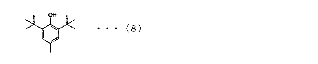
第26実施形態では、第1実施形態から第25実施形態のいずれかの非水系電解液において、以下の式(1)を有する化合物を含有することが好ましい。

第27実施形態では、第26実施形態の非水系電解液において、式(1)を有する化合物は、窒素含有環状化合物であることが好ましい。窒素含有環状化合物は、2環性窒素含有環状化合物であることが好ましい。

第28実施形態では、第13実施形態又は第14実施形態の非水系電解液において、リチウム塩の主成分が、イミド塩であり、或いは、前記イミド塩と、前記イミド塩以外の前記リチウム塩とが主成分として同量含まれることが好ましい。
第29実施形態では、第13実施形態、第14実施形態、第28実施形態のいずれかの非水系電解液において、LiPF6≦イミド塩となるモル濃度でイミド塩を含有することが好ましい。
第30実施形態では、第13実施形態、第14実施形態、第28実施形態、第29実施形態のいずれかの非水系電解液において、イミド塩の含有量が、非水系溶媒1Lに対して0.5mol以上3mol以下であることが好ましい。
第31実施形態では、第13実施形態、第14実施形態、第28実施形態から第30実施形態のいずれかの非水系電解液において、アセトニトリルに対するPF6アニオンの混合モル比が、0.01以上0.08未満であることが好ましい。
第32実施形態では、第1実施形態から第31実施形態のいずれかの非水系電解液において、リチウム塩が、PO2F2アニオンを含有することが好ましい。PO2F2アニオンは、LiPO2F2が電解液中で解離したものである。
第33実施形態では、第32実施形態の非水系電解液において、PO2F2アニオンの含有量が、非水系電解液に対し0.001質量%以上1質量%以下の範囲であることが好ましい。
第34実施形態では、第13実施形態、第14実施形態、第28実施形態、第30実施形態、第31実施形態のいずれかの非水系電解液において、イオン伝導における活性化エネルギーが、-20~0℃において、15kJ/mol以下であることが好ましい。
本実施形態の非水系電解液は、非水系二次電池に用いることができる。本実施形態の非水系二次電池としては、負極、正極、セパレータ、及び電池外装に対し、特に制限を与えるものではない。
非水系電解液については、上記した各実施形態に示した特徴的部分を具備していれば、従来のリチウムイオン電池の非水系電解液に用いられる材料を適用することができる。
本実施形態の非水系電解液は、リチウム塩について、各実施形態で限定していない限り、特に限定するものではない。例えば、本実施形態では、リチウム塩として、LiPF6やイミド塩を含む。
LiC(SO2R6)(SO2R7)(SO2R8) (10a)
LiN(SO2OR9)(SO2OR10) (10b)
LiN(SO2R11)(SO2OR12) (10c)
{式中、R6、R7、R8、R9、R10、R11、及びR12は、互いに同一であっても異なっていてもよく、炭素数1~8のパーフルオロアルキル基を示す。}のそれぞれで表される有機リチウム塩等が挙げられ、これらのうちの1種又は2種以上を、LiPF6と共に使用することができる。
本実施形態においては、非水系電解液に、例えば、無水酸、スルホン酸エステル、ジフェニルジスルフィド、シクロヘキシルベンゼン、ビフェニル、フルオロベンゼン、tert-ブチルベンゼン、リン酸エステル〔エチルジエチルホスホノアセテート(EDPA):(C2H5O)2(P=O)-CH2(C=O)OC2H5、リン酸トリス(トリフルオロエチル)(TFEP):(CF3CH2O)3P=O、リン酸トリフェニル(TPP):(C6H5O)3P=O:(CH2=CHCH2O)3P=O、リン酸トリアリル等〕等、及びこれらの化合物の誘導体等から選択される任意的添加剤を、適宜含有させることもできる。特に前記のリン酸エステルは、貯蔵時の副反応を抑制する作用があり、効果的である。
正極150は、正極合剤から作製した正極活物質層と、正極集電体とから構成される。正極150は、非水系二次電池の正極として作用するものであれば特に限定されず、公知のものであってもよい。
正極活物質としては、例えば、下記の式(11a)及び(11b):
LixMO2 (11a)
LiyM2O4 (11b)
{式中、Mは少なくとも1種の遷移金属元素を含む1種以上の金属元素を示し、xは0~1.1の数、yは0~2の数を示す。}のそれぞれで表されるリチウム含有化合物、及びその他のリチウム含有化合物が挙げられる。
LivMID2 (12a)
LiwMIIPO4 (12b)
{式中、Dは酸素又はカルコゲン元素を示し、MI及びMIIはそれぞれ1種以上の遷移金属元素を示し、v及びwの値は、電池の充放電状態により決まり、vは0.05~1.10、wは0.05~1.10の数を示す。}のそれぞれで表される化合物が挙げられる。
負極160は、負極合剤から作製した負極活物質層と、負極集電体とから構成される。負極160は、非水系二次電池の負極として作用するものであれば特に限定されず、公知のものであってもよい。
本実施形態における非水系二次電池100は、正極150及び負極160の短絡防止、シャットダウン等の安全性付与の観点から、正極150と負極160との間にセパレータ170を備えることが好ましい。セパレータ170としては、限定されるものではないが、公知の非水系二次電池に備えられるものと同様のものを用いてもよく、イオン透過性が大きく、機械的強度に優れる絶縁性の薄膜が好ましい。セパレータ170としては、例えば、織布、不織布、合成樹脂製微多孔膜等が挙げられ、これらの中でも、合成樹脂製微多孔膜が好ましい。
本実施形態における非水系二次電池100の電池外装110の構成は特に限定されないが、例えば、電池缶及びラミネートフィルム外装体のいずれかの電池外装を用いることができる。電池缶としては、例えば、スチール又はアルミニウムからなる金属缶を用いることができる。ラミネートフィルム外装体としては、例えば、熱溶融樹脂/金属フィルム/樹脂の3層構成からなるラミネートフィルムを用いることができる。
本実施形態の非水電解液は、非水系溶媒としてのアセトニトリルに、リチウム塩と、環状酸無水物と、更に、各実施形態に示す添加剤を、任意の手段で混合して製造することができる。なお、各添加剤の含有量は、各実施形態に示した通りである。
本実施形態における非水系二次電池100は、上述の非水系電解液、集電体の片面又は両面に正極活物質層を有する正極150、集電体の片面又は両面に負極活物質層を有する負極160、及び電池外装110、並びに必要に応じてセパレータ170を用いて、公知の方法により作製される。
第35実施形態では、集電体の片面又は両面に、正極活物質層を有する正極と、集電体の片面又は両面に、負極活物質層を有する負極と、非水系電解液と、を具備する非水系二次電池において、非水系二次電池に、-N=、-NH4、-N=O、-NH-NH-、及び(NO3)-からなる群から選ばれる少なくとも一種の官能基を有する化合物が含まれる。そして、非水系二次電池は、85℃での4時間保存試験後にて、5C放電容量を1C放電容量で除して算出してなる容量維持率は、70%以上であることを特徴とする。
第36実施形態では、集電体の片面又は両面に、正極活物質層を有する正極と、集電体の片面又は両面に、負極活物質層を有する負極と、非水系電解液と、を具備する非水系二次電池において、非水系二次電池に、有機酸およびその塩、無水酸、並びにLi2Oからなる群から選ばれる少なくとも一種の化合物が含まれる。このとき、有機酸は、酢酸、シュウ酸またはギ酸のうち少なくとも1種を含む。そして、非水系二次電池は、85℃での4時間保存試験後にて、5C放電容量を1C放電容量で除して算出してなる容量維持率は、70%以上であることを特徴とする。
第37実施形態では、集電体の片面又は両面に、正極活物質層を有する正極と、集電体の片面又は両面に、負極活物質層を有する負極と、非水系電解液と、を具備する非水系二次電池において、非水系二次電池に、-N=、-NH4、-N=O、-NH-NH-、及び(NO3)-からなる群から選ばれる少なくとも一種の官能基を有する化合物が含まれる。
第38実施形態では、集電体の片面又は両面に、正極活物質層を有する正極と、集電体の片面又は両面に、負極活物質層を有する負極と、非水系電解液と、を具備する非水系二次電池において、非水系二次電池に有機酸およびその塩、無水酸、並びにLi2Oからなる群から選ばれる少なくとも一種の化合物が含まれる。また、有機酸は、酢酸、シュウ酸またはギ酸のうち少なくとも1種を含む。そして、非水系二次電池は、85℃での4時間保存試験後における、0℃でのイオン伝導度が、10mS/cm以上であることを特徴とする。
第39実施形態では、第35実施形態から第38実施形態の非水系二次電池において、正極活物質がLizMO2(MはNiを含み、且つ、Mn、Co、Al、及びMgからなる群より選ばれる1種以上の金属元素を含み、さらに、Niの元素含有比は50%より多い。また、zは0.9超1.2未満の数を示す。)で表されるリチウム含有複合金属酸化物であることが、非水系二次電池のエネルギー密度を高める観点から好ましい。
第40実施形態では、第35実施形態から第39実施形態の非水系二次電池において、非水系電解液の注液前後における負極電位差が0.3V以上であることが好ましい。
第41実施形態では、第35実施形態から第40実施形態のいずれかの非水系二次電池において、60℃での200時間貯蔵試験におけるガス発生量が1mAhあたり0.008ml以下であることが好ましい。
第42実施形態では、第35実施形態から第41実施形態の非水系二次電池において、60℃での720時間満充電保存試験における抵抗増加率が400%以下であることが好ましい。
第43実施形態のセルパックは、第35実施形態から第42実施形態のいずれかに記載の非水系二次電池を備える。
第44実施形態のハイブリッドシステムは、第43実施形態に記載のセルパックと、リチウムイオン電池以外の二次電池から構成されるモジュールまたはセルパックと、を組み合わせてなることを特徴とする。
第45実施形態のセルパックは、第35実施形態から第42実施形態のいずれかに記載の非水系二次電池を備える。
式(2)
1モジュールあたりのセル直列接続数X:X=2,4,8、16
式(3)
セルパックあたりのモジュール直列接続数Y:Y=16/X
第46実施形態のハイブリッドシステムは、第45実施形態に記載のセルパックと、リチウムイオン電池以外の二次電池から構成されるモジュールまたはセルパックと、を組み合わせてなることを特徴とする。
(1-1) 正極の作製
正極活物質として数平均粒子径11μmのリチウムとニッケル、マンガン及びコバルトとの複合酸化物(Ni/Mn/Co=1/1/1(元素比);密度4.70g/cm3)と、導電助剤として数平均粒子径6.5μmのグラファイト炭素粉末(密度2.26g/cm3)及び数平均粒子径48nmのアセチレンブラック粉末(密度1.95g/cm3)と、バインダーとしてポリフッ化ビニリデン(PVdF;密度1.75g/cm3)とを、100:4.2:1.8:4.6の質量比で混合し、正極合剤を得た。得られた正極合剤に溶剤としてN-メチル-2-ピロリドンを固形分68質量%となるように投入して更に混合して、正極合剤含有スラリーを調製した。正極集電体となる厚さ20μm、幅200mmのアルミニウム箔の片面に、この正極合剤含有スラリーを目付量が12.0mg/cm2になるように調節しながらドクターブレード法で塗布し、溶剤を乾燥除去した。その後、ロールプレスで実電極密度が2.80g/cm3になるよう圧延して、正極活物質層と正極集電体からなる正極を得た。
負極活物質として数平均粒子径12.7μmのグラファイト炭素粉末(密度2.23g/cm3)及び数平均粒子径6.5μmのグラファイト炭素粉末(密度2.27g/cm3)と、バインダーとしてカルボキシメチルセルロース(密度1.60g/cm3)溶液(固形分濃度1.83質量%)と、ジエン系ゴム(ガラス転移温度:-5℃、乾燥時の数平均粒子径:120nm、密度1.00g/cm3、分散媒:水、固形分濃度40質量%)とを、87.2:9.7:1.4:1.7の固形分質量比で混合し、負極合剤を得た。得られた負極合剤に溶剤として水を固形分45質量%となるように投入して更に混合して、負極合剤含有スラリーを調製した。負極集電体となる厚さ10μm、幅200mmの銅箔の片面に、この負極合剤含有スラリーを目付量が5.3mg/cm2になるよう調節しながらドクターブレード法で塗布し、溶剤を乾燥除去した。その後、ロールプレスで実電極密度が1.30g/cm3になるよう圧延して、負極活物質層と負極集電体からなる負極を得た。
CR2032タイプの電池ケース(SUS304/Alクラッド)にポリプロピレン製ガスケットをセットし、その中央に上述のようにして得られた正極を直径16mmの円盤状に打ち抜いたものを、正極活物質層を上向きにしてセットした。その上からポリエチレン微多孔膜を直径19mmの円盤状に打ち抜いたものをセットして、電解液を100μL注入した後、上述のようにして得られた負極を直径16mmの円盤状に打ち抜いたものを、負極活物質層を下向きにしてセットした。さらにスペーサーとスプリングをセットした後に電池キャップをはめ込み、カシメ機でかしめた。あふれた電解液はウエスできれいにふきとった。25℃で24時間保持し、積層体に電解液を十分馴染ませてコイン型非水系二次電池を得た。
上述のようにして得られた評価用電池について、実施例および比較例に記載されているそれぞれの手順に従って初回充電処理後を行った。次に(2-1)、(2-2)の手順に従ってそれぞれの電池を評価した。なお、充放電はアスカ電子(株)製の充放電装置ACD-01(商品名)及び二葉科学社製の恒温槽PLM-63S(商品名)を用いて行った。
初回充放電処理(初回放電のエージング処理については各実施例や比較例の欄に記載)を行った電池について、電池の周囲温度を25℃に設定し、1Cに相当する3mAの定電流で充電して4.2Vに到達した後、4.2Vの定電圧で合計3時間充電を行った。次に、この非水系二次電池を85℃の恒温槽に4時間保存した。その後、電池の周囲温度を25℃に戻した。
上記(2-1)に記載の方法で85℃満充電保存試験を行った電池について、電池の周囲温度を25℃に設定し、1Cに相当する3mAの定電流で充電して4.2Vに到達した後、4.2Vの定電圧で合計3時間充電を行った。その後、1Cに相当する3mAの電流値で3.0Vまで放電した。次に、定電流放電時の電流値を5Cに相当する15mAに変更した以外は、上記と同様の充放電を行い、下記の容量維持率を算出した。
容量維持率=(5C放電時の容量/1C放電時の容量)×100[%]
不活性雰囲気下、アセトニトリル(AcN)とジエチルカーボネート(DEC)とエチレンカーボネート(EC)とビニレンカーボネート(VC)の体積比が45:35:16:4となるよう混合し混合溶媒を得た。さらに、この混合溶媒に無水コハク酸(環状酸無水物)を電解液として最終的に0.15質量%となるよう溶解させた。その後、混合溶媒1Lあたり0.3molのヘキサフルオロリン酸リチウム(LiPF6)と1.3molのリチウムビス(フルオロスルホニル)イミド(LiN(SO2F)2)を添加し、実施例1の電解液を得た。得られた電解液について、目視でリチウム塩が全て溶解していることを確認した。この電解液を用いて上記(1-3)に記載の方法で電池作製した後、初回充放電処理を行った。電池の周囲温度を25℃に設定し、0.1Cに相当する0.3mAの定電流で充電して2.8Vまで充電した後、2.8Vの定電圧で1.5時間充電を行った。その後、周囲温度を55℃に設定し、6時間保存した後、再び電池の周囲温度を25℃に設定し、冷却のため3時間静置した。その後、0.1Cに相当する0.3mAの定電流で充電して4.2Vに到達した後、4.2Vの定電圧で合計1.5時間充電を行った。その後、0.3Cに相当する0.9mAの定電流で3.0Vまで放電した。このときの放電容量を充電容量で割ることによって、初回効率を算出した。その後、上記(2-1)、(2-2)に記載の手順でコイン型非水系二次電池の評価を行った。
不活性雰囲気下、アセトニトリル(AcN)とエチルメチルカーボネート(EMC)とエチレンカーボネート(EC)とビニレンカーボネート(VC)の体積比が45:35:16:4となるよう混合し混合溶媒を得た。さらに、この混合溶媒に無水コハク酸(環状酸無水物)を電解液として最終的に0.3質量%となるよう溶解させた。その後、混合溶媒1Lあたり1.3molのヘキサフルオロリン酸リチウム(LiPF6)を添加し、実施例2の電解液を得た。得られた電解液について、目視でリチウム塩が全て溶解していることを確認した。この電解液を用いて上記(1-3)に記載の方法で電池作製した後、初回充放電処理を行った。電池の周囲温度を25℃に設定し、0.1Cに相当する0.3mAの定電流で充電して2.8Vまで充電した後、2.8Vの定電圧で1.5時間充電を行った。その後、周囲温度を45℃に設定し、72時間保存した後、再び電池の周囲温度を25℃に設定し、冷却のため3時間静置した。その後、0.1Cに相当する0.3mAの定電流で充電して4.2Vに到達した後、4.2Vの定電圧で合計1.5時間充電を行った。その後、0.3Cに相当する0.9mAの定電流で3.0Vまで放電した。このときの放電容量を充電容量で割ることによって、初回効率を算出した。その後、上記(2-1)(2-2)に記載の手順でコイン型非水系二次電池の評価を行った。
不活性雰囲気下、アセトニトリル(AcN)とエチルメチルカーボネート(EMC)とエチレンカーボネート(EC)とビニレンカーボネート(VC)の体積比が35:40:21:4となるよう混合し混合溶媒を得た。さらに、この混合溶媒に無水マレイン酸(環状酸無水物)を電解液として最終的に0.15質量%となるよう溶解させた。その後、混合溶媒1Lあたり1.2molのヘキサフルオロリン酸リチウム(LiPF6)を添加し、実施例3の電解液を得た。得られた電解液について、目視でリチウム塩が全て溶解していることを確認した。この電解液を用いて上記(1-3)に記載の方法で電池作製した後、初回充放電処理を行った。電池の周囲温度を25℃に設定し、0.1Cに相当する0.3mAの定電流で充電して3.0Vまで充電した後、3.0Vの定電圧で1.5時間充電を行った。その後、周囲温度を55℃に設定し、6時間保存した後、再び電池の周囲温度を25℃に設定し、冷却のため3時間静置した。その後、0.1Cに相当する0.3mAの定電流で充電して4.2Vに到達した後、4.2Vの定電圧で合計1.5時間充電を行った。その後、0.3Cに相当する0.9mAの定電流で3.0Vまで放電した。このときの放電容量を充電容量で割ることによって、初回効率を算出した。その後、上記(2-1)(2-2)に記載の手順でコイン型非水系二次電池の評価を行った。
不活性雰囲気下、アセトニトリル(AcN)とジメチルカーボネート(DMC)とエチレンカーボネート(EC)とビニレンカーボネート(VC)の体積比が57:14:22:7となるよう混合し混合溶媒を得た。さらに、この混合溶媒に無水フタル酸(環状酸無水物)を電解液として最終的に0.5質量%となるよう溶解させた。その後、混合溶媒1Lあたり0.6molのヘキサフルオロリン酸リチウム(LiPF6)と0.6molのリチウムビス(トリフルオロメタンスルホニル)イミド(LiN(SO2CF3)2)を添加し、実施例4の電解液を得た。 得られた電解液について、目視でリチウム塩が全て溶解していることを確認した。この電解液を用いて上記(1-3)に記載の方法で電池作製した後、初回充放電処理を行った。電池の周囲温度を25℃に設定し、0.1Cに相当する0.3mAの定電流で充電して3.0Vまで充電した後、3.0Vの定電圧で1.5時間充電を行った。その後、周囲温度を60℃に設定し、6時間保存した後、再び電池の周囲温度を25℃に設定し、冷却のため3時間静置した。その後、0.1Cに相当する0.3mAの定電流で充電して4.2Vに到達した後、4.2Vの定電圧で合計1.5時間充電を行った。その後、0.3Cに相当する0.9mAの定電流で3.0Vまで放電した。このときの放電容量を充電容量で割ることによって、初回効率を算出した。その後、上記(2-1)(2-2)に記載の手順でコイン型非水系二次電池の評価を行った。
不活性雰囲気下、アセトニトリル(AcN)とジエチルカーボネート(DEC)とビニレンカーボネート(VC)の体積比が47:42:11となるよう混合した。さらにこの混合液1Lあたり1.3molのヘキサフルオロリン酸リチウム(LiPF6)を添加して、比較例1の電解液を得た。得られた電解液について、目視でリチウム塩が全て溶解していることを確認した。この電解液を用いて上記(1-3)に記載の方法で電池作製した後、初回充放電処理を行った。電池の周囲温度を25℃に設定し、0.1Cに相当する0.3mAの定電流で充電して4.2Vに到達した後、4.2Vの定電圧で合計1.5時間充電を行った。その後、0.3Cに相当する0.9mAの定電流で3.0Vまで放電した。このときの放電容量を充電容量で割ることによって、初回効率を算出した。その後、上記(2-1)(2-2)に記載の手順でコイン型非水系二次電池の評価を行った。比較例1では、初回充電のエージング処理を行っていない。
不活性雰囲気下、アセトニトリル(AcN)とジエチルカーボネート(DEC)とビニレンカーボネート(VC)の体積比が47:49:4となるよう混合した。さらにこの混合液1Lあたり0.3molのヘキサフルオロリン酸リチウム(LiPF6)と1.0molのリチウムビス(フルオロスルホニル)イミド(LiN(SO2F)2)を添加して、比較例2の電解液を得た。得られた電解液について、目視でリチウム塩が全て溶解していることを確認した。この電解液を用いて上記(1-3)に記載の方法で電池作製した後、初回充放電処理を行った。電池の周囲温度を25℃に設定し、0.1Cに相当する0.3mAの定電流で充電して2.8Vまで充電した後、2.8Vの定電圧で1.5時間充電を行った。その後、周囲温度を25℃のままとし、72時間保存した後、電池の周囲温度をそのまま25℃に設定し、3時間静置した。その後、0.1Cに相当する0.3mAの定電流で充電して4.2Vに到達した後、4.2Vの定電圧で合計1.5時間充電を行った。その後、0.3Cに相当する0.9mAの定電流で3.0Vまで放電した。このときの放電容量を充電容量で割ることによって、初回効率を算出した。その後、上記(2-1)(2-2)に記載の手順でコイン型非水系二次電池の評価を行った。
不活性雰囲気下、アセトニトリル(AcN)とジエチルカーボネート(DEC)とビニレンカーボネート(VC)の体積比が47:49:4となるよう混合し混合溶媒を得た。その後、混合溶媒1Lあたり0.3molのヘキサフルオロリン酸リチウム(LiPF6)と1.0molのリチウムビス(トリフルオロメタンスルホニル)イミド(LiN(SO2CF3)2)を添加し、比較例3の電解液を得た。得られた電解液について、目視でリチウム塩が全て溶解していることを確認した。この電解液を用いて上記(1-3)に記載の方法で電池作製した後、初回充放電処理を行った。電池の周囲温度を25℃に設定し、0.1Cに相当する0.3mAの定電流で充電して4.2Vまで充電した後、4.2Vの定電圧で合計1.5時間充電を行った。その後、周囲温度を85℃とし、24時間保存した後、電池の周囲温度をそのまま25℃に設定し、冷却のため3時間静置した。その後、0.1Cに相当する0.3mAの定電流で充電して4.2Vに到達した後、4.2Vの定電圧で1.5時間充電を行った。その後、0.3Cに相当する0.9mAの定電流で3.0Vまで放電した。このときの放電容量を充電容量で割ることによって、初回効率を算出した。その後、上記(2-1)(2-2)に記載の手順でコイン型非水系二次電池の評価を行った。
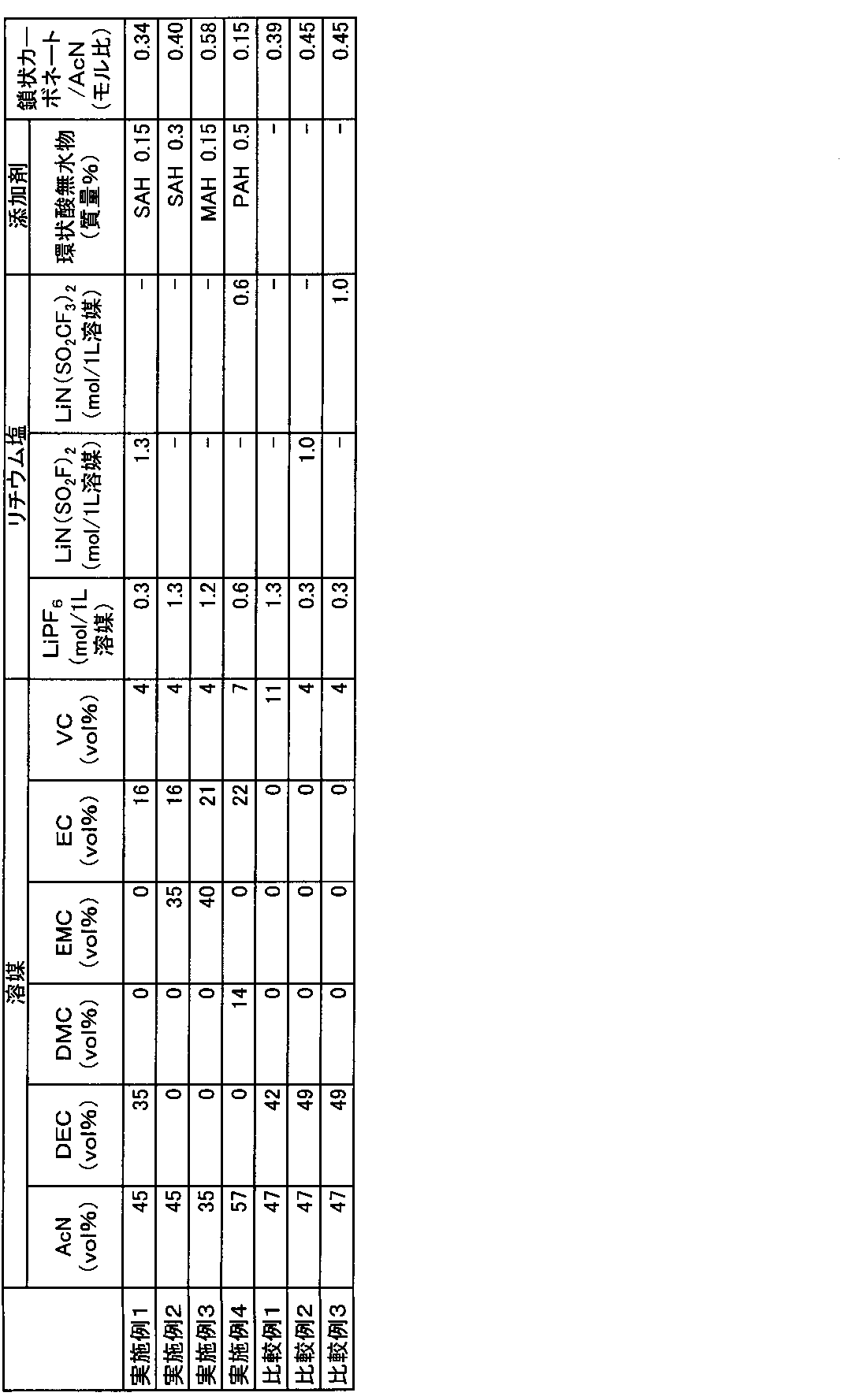
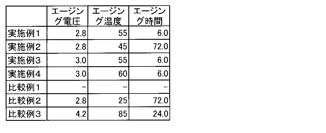
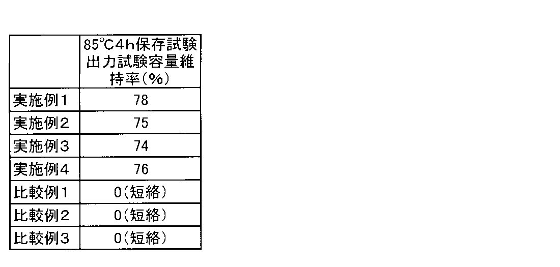
(1-1) 正極の作製
正極活物質としてリチウム、ニッケル、マンガン、及びコバルトの複合酸化物(LiNi1/3Mn1/3Co1/3O2)と、導電助剤としてアセチレンブラック粉末と、バインダーとしてポリフッ化ビニリデン(PVDF)とを、86:8:6の質量比で混合し、正極合剤を得た。得られた正極合剤に溶剤としてN-メチル-2-ピロリドンを投入して更に混合して、正極合剤含有スラリーを調製した。この正極合剤含有スラリーを、正極集電体となるアルミニウム箔両面に、片面あたりの目付量が11.5mg/cm2になるように調節しながら塗布した。正極合剤含有スラリーをアルミニウム箔に塗布する際には、アルミニウム箔の一部が露出するように未塗布領域を形成した。その後、ロールプレスで合材層の密度が2.8mg/cm3になるように圧延することにより、正極活物質層と正極集電体とからなる正極を得た。
負極活物質であるグラファイトと、導電助剤であるアセチレンブラックと、バインダーであるPVDFとを86:7:7の質量比で混合し、負極合剤を得た。得られた負極合剤に適量の水を添加した後に十分に混合して、負極合剤含有スラリーを調製した。この負極合剤含有スラリーを、銅箔の両面に、片面あたりの目付量が6.9mg/cm2になるように調節しながら塗布した。負極合剤含有スラリーを銅箔に塗布する際には、銅箔の一部が露出するように未塗布領域を形成した。その後、ロールプレスで合材層の密度が1.3mg/cm3になるように圧延することにより、負極活物質層と負極集電体とからなる負極を得た。
リード付き正極とリード付き負極とを、各極の合剤塗布面が対向するようにポリエチレン製樹脂フィルムを介して重ね合わせて積層電極体とした。この積層電極体をアルミニウムラミネートシート外装体内に収容し、水分を除去するために80℃で5h真空乾燥を行った。続いて、電解液を外装体内に注入した後、外装体を封止することにより、積層ラミネート型非水系二次電池(パウチ型セル電池。以下、単に「積層ラミネート電池」ともいう。)を作製した。
上述のようにして得られた積層ラミネート電池について、以下の手順に従って初回充放電処理を行った。次に容量を測定し、続いて2C過充電試験を実施して、60℃になるまでの時間(分)を測定した。
積層ラミネート電池の周囲温度を25℃に設定し、0.2Cの電流値で4.2Vまで定電流充電を行った後、4.2Vで1時間の定電圧充電を行った。その後、0.2Cに相当する定電流で2.7Vになるまで放電した。その後、露点-60℃以下に制御されたグローブボックス内にて、電池の封止部を開口しガス抜きを行った。ガス抜き後、同じ環境下において真空シールを行った。
上記初回充放電処理後の積層ラミネート電池について、25℃において、0.2Cの電流値で4.2Vまで定電流充電を行った後、4.2Vで1時間の定電圧充電を行い、その後、0.2Cに相当する定電流で2.7Vになるまで放電した。これらの操作を計3回行い、その後0.2Cの電流値で4.2Vまで定電流充電を行った後、4.2Vで1時間の定電圧充電を行った充電後の積層ラミネート電池を、25℃で24時間保存した。
上記容量測定後の積層ラミネート電池について、25℃において0.2Cの電流値で4.2Vになるまで定電流充電を行った後、4.2Vで1時間の定電圧充電を行った。この充電後の積層ラミネート電池を、電極端子には電流負荷線と電圧計測線を取り付け、電池表面に熱電対を取り付けた状態で約350mm角の金属製試験容器に設置した。容器内はアルゴンガス雰囲気に置換して試験を行った。
下記の表4に示す各種溶媒及び添加剤を所定量混ぜることで電解液を調製した。すなわち、アセトニトリル(AcN)と、ジエチルカーボネート(DEC)と、エチレンカーボネート(EC)と、ビニレンカーボネート(VC)の体積比が47:38:11:4となるように加えて混合した。さらにこの混合液1Lあたり0.3molのヘキサフルオロリン酸リチウム(LiPF6)と1.1molのLiN(SO2F)2(LiFSI)を添加した。また、水を50ppm及び、環状酸無水物として無水コハク酸(SAH)を0.2質量%添加して、実施例5の電解液を得た。この電解液について上記(1-3)に記載の方法で電池作製した後、上記(2-1)~(2-3)に記載の手順で、積層ラミネート電池の評価を行った。
下記の表4に示す各種溶媒及び添加剤を所定量混ぜることで電解液を調製した。すなわち、アセトニトリル(AcN)と、ジエチルカーボネート(DEC)と、エチレンカーボネート(EC)と、ビニレンカーボネート(VC)の体積比が39:35:21:5となるように加えて混合した。さらにこの混合液1Lあたり1.3molのヘキサフルオロリン酸リチウム(LiPF6)を添加した。また、水を100ppm及び、環状酸無水物として無水マレイン酸(MAH)を0.15質量%添加して、実施例6の電解液を得た。この電解液について上記(1-3)に記載の方法で電池作製した後、上記(2-1)~(2-3)に記載の手順で、積層ラミネート電池の評価を行った。
下記の表4に示す各種溶媒及び添加剤を所定量混ぜることで電解液を調製した。すなわち、アセトニトリル(AcN)と、ジメチルカーボネート(DMC)と、エチレンカーボネート(EC)と、ビニレンカーボネート(VC)の体積比が65:8:22:5となるように加えて混合した。さらにこの混合液1Lあたり0.6molのヘキサフルオロリン酸リチウム(LiPF6)と0.05molのリチウムビスオキサレートボレート(LiB(C2O4)2)(LiBOB)と0.6molのリチウムビス(フルオロスルホニル)イミド(LiN(SO2F)2)(LiFSI)を添加した。また、水を75ppm及び、環状酸無水物として無水フタル酸(PAH)を、0.5質量%添加して、実施例7の電解液を得た。この電解液について上記(1-3)に記載の方法で電池作製した後、上記(2-1)~(2-3)に記載の手順で、積層ラミネート電池の評価を行った。
下記の表4に示す各種溶媒及び添加剤を所定量混ぜることで電解液を調製した。すなわち、アセトニトリル(AcN)と、ジエチルカーボネート(DEC)と、ビニレンカーボネート(VC)と、エチレンサルファイト(ES)の体積比が47:38:11:4となるように加えて混合した。さらにこの混合液1Lあたり1.3molのヘキサフルオロリン酸リチウム(LiPF6)と0.05molのリチウムビスオキサレートボレート(LiB(C2O4)2)(LiBOB)を添加した。また、環状酸無水物として無水コハク酸(SAH)を、0.05質量%添加して、比較例4の電解液を得た。なお、比較例4では、水を加えていない。この電解液について上記(1-3)に記載の方法で電池作製した後、上記(2-1)~(2-3)に記載の手順で、積層ラミネート電池の評価を行った。
下記の表4に示す各種溶媒及び添加剤を所定量混ぜることで電解液を調製した。すなわち、アセトニトリル(AcN)と、ジエチルカーボネート(DEC)と、ビニレンカーボネート(VC)の体積比が47:42:11となるように加えて混合した。さらにこの混合液1Lあたり1.3molのヘキサフルオロリン酸リチウム(LiPF6)を添加すると共に、水を200ppm添加して、比較例5の電解液を得た。この電解液について上記(1-3)に記載の方法で電池作製した後、上記(2-1)~(2-3)に記載の手順で、積層ラミネート電池の評価を行った。
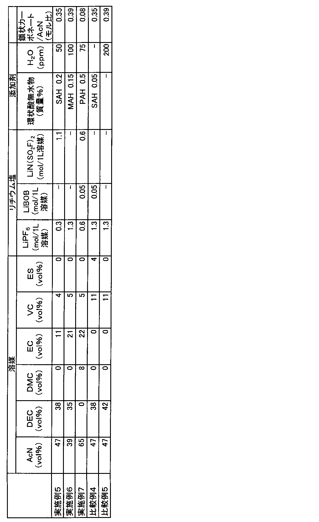

[電解液の調製]
不活性雰囲気下、1Lのアセトニトリルに対して、各種イミド塩を、表6に示す含有量(モル量)で溶解させた。次に、得られた混合液のアセトニトリル、及び、その他の溶媒を、表6に示す組成で混合した。さらに得られた混合液に、表6に示す含有量でヘキサフルオロリン酸リチウム(LiPF6)、水(H2O)、及び各種環状酸無水物を添加、溶解させ、実施例8から実施例11及び比較例6から比較例8の電解液を得た。なお、表6おいて「AcN」はアセトニトリル、「DEC」はジエチルカーボネート、「DMC」はジメチルカーボネート、「EC」はエチレンカーボネート、「VC」はビニレンカーボネート、「LiPF6」はヘキサフルオロリン酸リチウム、「LiN(SO2F)2」はリチウムビス(フルオロスルホニル)イミド、「LiN(SO2CF3)2」はリチウムビス(トリフルオロメタンスルホニル)イミド、「SAH」は無水コハク酸、「MAH」は無水マレイン酸、「PAH」は無水フタル酸をそれぞれ示す。
PF6/AcN(モル比)=LiPF6のモル量/AcNのモル量

実施例8から実施例11、比較例6から比較例8の電解液について、以下に記載の方法で電池作製した後、以下に記載の手順でコイン型非水系二次電池の評価を行った。結果を表7、表8に示す。
(1-1)正極の作製
(A)正極活物質として、数平均粒子径11μmのリチウムと、ニッケル、マンガン及びコバルトとの複合酸化物(Ni/Mn/Co=1/1/1(元素比);密度4.70g/cm3)と、導電助剤として、(B)数平均粒子径6.5μmのグラファイト炭素粉末(密度2.26g/cm3)及び(C)数平均粒子径48nmのアセチレンブラック粉末(密度1.95g/cm3)と、(D)バインダーとして、ポリフッ化ビニリデン(PVdF;密度1.75g/cm3)と、を、100:4.2:1.8:4.6の質量比で混合し、正極合剤を得た。
(a)負極活物質として数平均粒子径12.7μmのグラファイト炭素粉末(密度2.23g/cm3)及び(b)数平均粒子径6.5μmのグラファイト炭素粉末(密度2.27g/cm3)と、(c)バインダーとしてカルボキシメチルセルロース(密度1.60g/cm3)溶液(固形分濃度1.83質量%)と、(d)ジエン系ゴム(ガラス転移温度:-5℃、乾燥時の数平均粒子径:120nm、密度1.00g/cm3、分散媒:水、固形分濃度40質量%)とを、87.2:9.7:1.4:1.7の固形分質量比で混合し、負極合剤を得た。
CR2032タイプの電池ケース(SUS304/Alクラッド)にポリプロピレン製ガスケットをセットし、その中央に上述のようにして得られた正極を直径16mmの円盤状に打ち抜いたものを、正極活物質層を上向きにしてセットした。その上からガラス繊維濾紙(アドバンテック社製ガラス繊維濾紙 GA-100)を直径16mmの円盤状に打ち抜いたものをセットして、電解液を150μL注入した後、上述のようにして得られた負極を直径16mmの円盤状に打ち抜いたものを、負極活物質層を下向きにしてセットした。さらにスペーサーとスプリングをセットした後に電池キャップをはめ込み、カシメ機でかしめた。あふれた電解液はウエスできれいにふきとった。25℃で24時間保持し、積層体に電解液を十分馴染ませてコイン型非水系二次電池を得た。
上述のようにして得られた評価用電池について、まず、下記(2-1)の手順に従って初回充電処理を行った。次に(2-2)の手順に従ってそれぞれの電池を評価した。なお、充放電はアスカ電子(株)製の充放電装置ACD-01(商品名)及び二葉科学社製の恒温槽PLM-63S(商品名)を用いて行った。
電池の周囲温度を25℃に設定し、0.1Cに相当する0.6mAの定電流で充電して4.2Vに到達した後、4.2Vの定電圧で合計1.5時間充電を行った。その後、0.3Cに相当する1.8mAの定電流で3.0Vまで放電した。このときの放電容量を充電容量で割ることによって、初回効率を算出した。この結果を、表7に示す。
上記(2-1)に記載の方法で初回充放電処理を行った電池について、電池の周囲温度を25℃に設定し、1Cに相当する6mAの定電流で充電して4.2Vに到達した後、4.2Vの定電圧で合計3時間充電を行った。その後、1Cに相当する6mAの電流値で3.0Vまで放電した。次に、定電流放電時の電流値を5Cに相当する30mAに変更した以外は同様の充放電を行った。出力試験後、5Cに相当する30mAの電流値の放電曲線について確認を行った。放電曲線は、横軸に時間、横軸に電池電圧をプロットした。
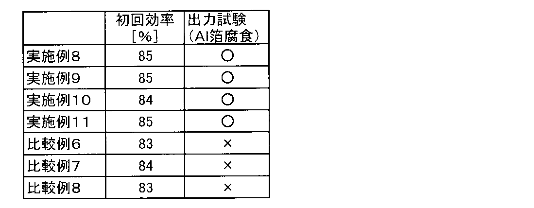
上述のようにして得られた評価用電池について、電池の周囲温度を25℃に設定し、1Cに相当する6mAの定電流で充電して4.2Vに到達した後、4.2Vの定電圧で合計3時間充電を行った。その後、60℃で100時間保存し、電解液中へのアルミニウム(Al)溶出量(単位:ppm)を測定した。
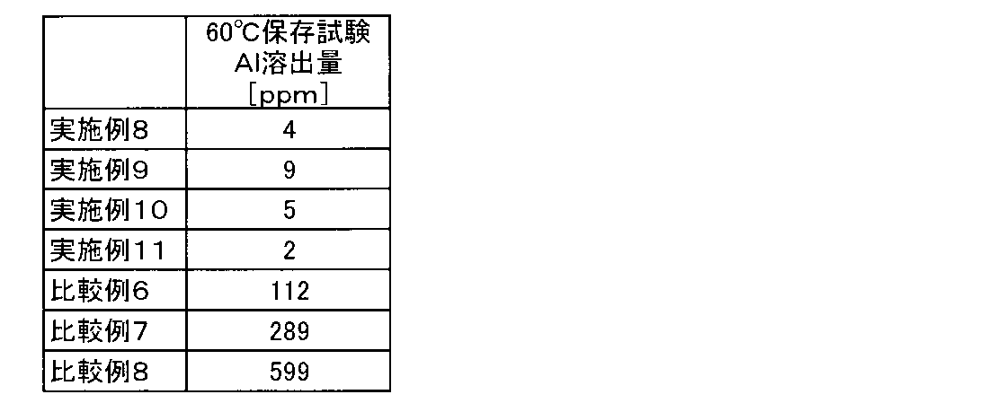
[電解液の調製]
各種溶媒及び電解質を所定の体積比になるように混ぜることで電解液を調製した。実施例及び比較例で用いた各電解液の組成は表9に示した。なお、表9において「AcN」はアセトニトリル、「DEC」はジエチルカーボネート、「EMC」はエチルメチルカーボネート、「EC」はエチレンカーボネート、「VC」はビニレンカーボネート、「PC」は、プロピレンカーボネート、「LiPF6」はヘキサフルオロリン酸リチウム、「LiN(SO2F)2」はリチウムビス(フルオロスルホニル)イミド、「SAH」は無水コハク酸、「MAH」は無水マレイン酸をそれぞれ示す。

アルゴンボックス内で、実施例及び比較例の電解液をNMRチューブ内管(直径3mm)に採取し、蓋をした後、パラフィルムを用いて封をした。アルゴンボックスからNMRチューブ内管を取り出し、C6H2F4を添加したDMSO-d6溶液の入った外管に挿し込み、二重管法によるNMR測定を行った。NMR測定装置は、JEOL RESONANCE社製ECS400を用いた。測定条件は、パルス幅45℃、積算回数256回、昇温時の待ち時間は25℃が5秒、60℃が7秒、85℃が10秒で行った。試験結果を表9に示す。
各種溶媒及び添加剤を所定の体積比になるように混ぜることで電解液を調製した。実施例及び比較例で用いた各電解液の組成は表10に示した。なお、表10において「AcN」はアセトニトリル、「DEC」はジエチルカーボネート、「DMC」はジメチルカーボネート、「EMC」はエチルメチルカーボネート、「EC」はエチレンカーボネート、「VC」はビニレンカーボネート、「LiPF6」はヘキサフルオロリン酸リチウム、「LiN(SO2F)2」はリチウムビス(フルオロスルホニル)イミド、「SAH」は無水コハク酸をそれぞれ示す。

〔正極の作製〕
正極活物質としてリチウム、ニッケル、マンガン、及びコバルトの複合酸化物(LiNi0.5Mn0.3Co0.2O2)と、導電助剤としてアセチレンブラック粉末と、バインダーとしてポリフッ化ビニリデン(PVDF)とを、100:3.5:3の質量比で混合し、正極合剤を得た。得られた正極合剤に溶剤としてN-メチル-2-ピロリドンを投入して更に混合して、正極合剤含有スラリーを調製した。正極集電体となる厚さ15μmのアルミニウム箔片面に、この正極合剤含有スラリーを、目付量が約95.0g/m2になるように調節しながら塗布した。正極合剤含有スラリーをアルミニウム箔に塗布する際には、アルミニウム箔の一部が露出するように未塗布領域を形成した。その後、ロールプレスで正極活物質層の密度が2.74g/cm3になるように圧延することにより、正極活物質層と正極集電体とからなる正極を得た。
負極活物質である黒鉛と、バインダーであるカルボキシメチルセルロースと、同じくバインダーであるスチレンブタジエンラテックスとを、100:1.1:1.5の質量比で混合し、負極合剤を得た。得られた負極合剤に適量の水を添加した後に十分に混合して、負極合剤含有スラリーを調製した。このスラリーを、厚みが10μmの銅箔の片面に、目付量が約61.0g/m2になるように調節しながら一定厚みで塗布した。負極合剤含有スラリーを銅箔に塗布する際には、銅箔の一部が露出するように未塗布領域を形成した。その後、ロールプレスで負極活物質層の密度が1.20g/cm3になるように圧延することにより、負極活物質層と負極集電体とからなる負極を得た。
リード付き正極とリード付き負極とを、各極の合剤塗布面が対向するようにポリエチレン製微多孔膜セパレータ(厚み21μm)を介して重ね合わせて積層電極体とした。この積層電極体を、90mm×80mmのアルミニウムラミネートシート外装体内に収容し、水分を除去するために80℃で5時間真空乾燥を行った。続いて、上記した各電解液を外装体内に注入した後、外装体を封止することにより、単層ラミネート型(パウチ型)非水系二次電池(以下、単に「単層ラミネート電池」ともいう。)を作製した。この単層ラミネート電池は、設計容量値が23mAh、定格電圧値が4.2Vのものである。
上述のようにして得られた評価用電池について、まず、下記(1-1)の手順に従って初回充電処理を行った。次に(1-2)の手順に従ってそれぞれの電池を評価した。なお、充放電はアスカ電子(株)製の充放電装置ACD-01(商品名)及び二葉科学社製の恒温槽PLM-63S(商品名)を用いて行った。
電池の周囲温度を25℃に設定し、0.1Cに相当する2.3mAの定電流で充電して4.2Vに到達した後、4.2Vの定電圧で合計1.5時間充電を行った。その後、0.3Cに相当する6.9mAの定電流で2.5Vまで放電した。このときの放電容量を充電容量で割ることによって、初回効率を算出した。
上記(1-1)に記載の方法で初回充放電処理を行った電池について、サイクル試験を実施した。なお、サイクル試験は電池の周囲温度を-10℃に設定した3時間後に開始した。まず、0.2Cに相当する4.6mAの定電流で充電して4.2Vに到達した後、4.2Vの定電圧で合計3時間充電を行った。その後、4.6mAの定電流で2.5Vまで放電した。充電と放電とを各々1回ずつ行うこの工程を1サイクルとし、20サイクルの充放電を行った。1サイクル目の放電容量を100%としたときの20サイクル目の放電容量を容量維持率とした。
上記(1-1)に記載の方法で初回充放電処理を行った電池について、交流インピーダンス測定を実施した。交流インピーダンス測定は、ソーラトロン社製周波数応答アナライザ1400(商品名)とソーラトロン社製ポテンショ-ガルバノスタット1470E(商品名)を用いた。1000kHz~0.01Hzに周波数を変えつつ交流信号を付与し、電圧・電流の応答信号からインピーダンスを測定し、複素インピーダンス平面プロット(cole-coleプロット)の横軸と交差した値をバルク抵抗、高周波数側の円弧の横幅を界面抵抗として求めた。また、抵抗値はいずれも実数部(横軸)の値を使用した。印可する交流電圧の振幅は±5mVとした。また、交流インピーダンスを測定する際の電池の周囲温度は25℃で実施し、測定は各温度設定の1時間30分後に開始した。また、これらの結果から下記の値を算出した。
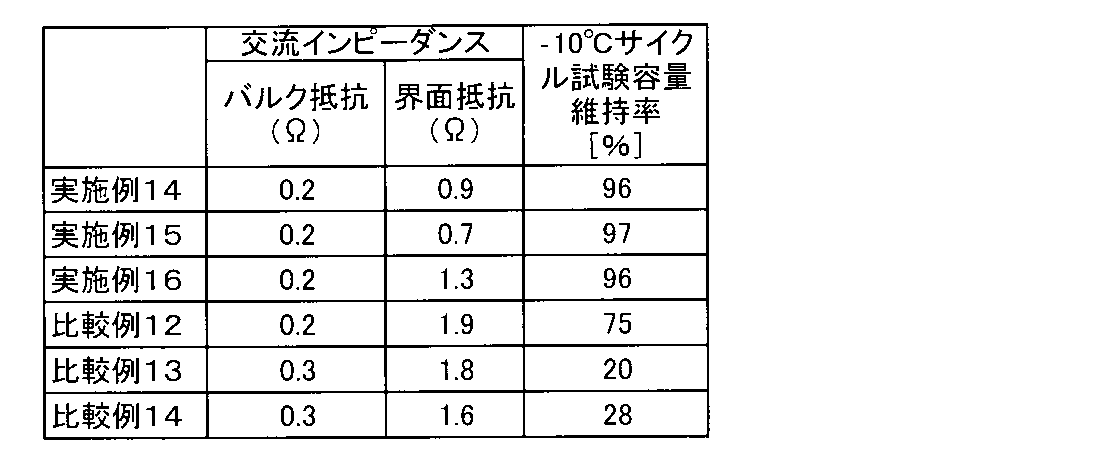
(1-1)正極の作製
正極活物質として数平均粒子径11μmのリチウムとニッケル、マンガン及びコバルトとの複合酸化物(Ni/Mn/Co=1/1/1(元素比);密度4.70g/cm3)と、導電助剤として数平均粒子径6.5μmのグラファイト炭素粉末(密度2.26g/cm3)及び数平均粒子径48nmのアセチレンブラック粉末(密度1.95g/cm3)と、バインダーとしてポリフッ化ビニリデン(PVdF;密度1.75g/cm3)とを、100:4.2:1.8:4.6の質量比で混合し、正極合剤を得た。得られた正極合剤に溶剤としてN-メチル-2-ピロリドンを固形分68質量%となるように投入して更に混合して、正極合剤含有スラリーを調製した。正極集電体となる厚さ20μm、幅200mmのアルミニウム箔の片面に、この正極合剤含有スラリーを目付量が12.0mg/cm2になるように調節しながらドクターブレード法で塗布し、溶剤を乾燥除去した。その後、ロールプレスで実電極密度が2.80g/cm3になるよう圧延して、正極活物質層と正極集電体からなる正極を得た。
負極活物質として数平均粒子径12.7μmのグラファイト炭素粉末(密度2.23g/cm3)及び数平均粒子径6.5μmのグラファイト炭素粉末(密度2.27g/cm3)と、バインダーとしてカルボキシメチルセルロース(密度1.60g/cm3)溶液(固形分濃度1.83質量%)と、ジエン系ゴム(ガラス転移温度:-5℃、乾燥時の数平均粒子径:120nm、密度1.00g/cm3、分散媒:水、固形分濃度40質量%)とを、87.2:9.7:1.4:1.7の固形分質量比で混合し、負極合剤を得た。得られた負極合剤に溶剤として水を固形分45質量%となるように投入して更に混合して、負極合剤含有スラリーを調製した。負極集電体となる厚さ10μm、幅200mmの銅箔の片面に、この負極合剤含有スラリーを目付量が5.3mg/cm2になるよう調節しながらドクターブレード法で塗布し、溶剤を乾燥除去した。その後、ロールプレスで実電極密度が1.30g/cm3になるよう圧延して、負極活物質層と負極集電体からなる負極を得た。
CR2032タイプの電池ケース(SUS304/Alクラッド)にポリプロピレン製ガスケットをセットし、その中央に上述のようにして得られた正極を直径16mmの円盤状に打ち抜いたものを、正極活物質層を上向きにしてセットした。その上からガラス繊維濾紙(アドバンテック社製ガラス繊維濾紙 GA-100)を直径16mmの円盤状に打ち抜いたものをセットして、電解液を150μL注入した後、上述のようにして得られた負極を直径16mmの円盤状に打ち抜いたものを、負極活物質層を下向きにしてセットした。さらにスペーサーとスプリングをセットした後に電池キャップをはめ込み、カシメ機でかしめた。あふれた電解液はウエスできれいにふきとった。25℃で24時間保持し、積層体に電解液を十分馴染ませてコイン型非水系二次電池を得た。
上述のようにして得られた評価用電池について、まず、下記(2-1)の手順に従って初回充電処理を行った。次に(2-2)の手順に従ってそれぞれの電池を評価した。なお、充放電はアスカ電子(株)製の充放電装置ACD-01(商品名)及び二葉科学社製の恒温槽PLM-63S(商品名)を用いて行った。
電池の周囲温度を25℃に設定し、0.1Cに相当する0.3mAの定電流で充電して4.2Vに到達した後、4.2Vの定電圧で合計1.5時間充電を行った。その後、0.3Cに相当する0.9mAの定電流で3.0Vまで放電した。このときの放電容量を充電容量で割ることによって、初回効率を算出した。
上記(2-1)に記載の方法で初回充放電処理を行った電池について、電池の周囲温度を50℃に設定し、1Cに相当する3mAの定電流で充電して4.2Vに到達した後、4.2Vの定電圧で合計3時間充電を行った。その後、3mAの定電流で3Vまで放電した。充電と放電とを各々1回ずつ行うこの工程を1サイクルとし、100サイクルの充放電を行った。1サイクル目の放電容量を100%としたときの100サイクル目の放電容量を容量維持率とした。
不活性雰囲気下、アセトニトリル(AcN)とジエチルカーボネート(DEC)とエチレンカーボネート(EC)とビニレンカーボネート(VC)の体積比が60:25:11:4となるよう混合した。更に、この混合液1Lあたり0.35molのヘキサフルオロリン酸リチウム(LiPF6)と1.8molのリチウムビス(フルオロスルホニル)イミド(LiN(SO2F)2)を溶解させると共に、下記の式(4)に示す有機塩素化合物を5ppmと、環状酸無水物として無水コハク酸を0.2質量%加え混合し、実施例17の電解液を得た。得られた電解液について、目視でリチウム塩、塩化物および環状酸無水物が全て溶解していることを確認した。この電解液について上記(1-3)に記載の方法で電池作製した後、上記(2-1)~(2-2)に記載の手順で測定を行った。

不活性雰囲気下、アセトニトリル(AcN)とジエチルカーボネート(DEC)とエチルメチルカーボネート(EMC)とエチレンカーボネート(EC)とビニレンカーボネート(VC)の体積比が38:18:18:20:6となるよう混合した。更に、この混合液1Lあたり1.2molのヘキサフルオロリン酸リチウム(LiPF6)と0.3molのリチウムビス(フルオロスルホニル)イミド(LiN(SO2F)2)を溶解させると共に、下記の式(5)に示す有機塩素化合物を0.5ppmと、環状酸無水物として無水マレイン酸を0.15質量%加え混合し、実施例18の電解液を得た。得られた電解液について、目視でリチウム塩、塩化物および環状酸無水物が全て溶解していることを確認した。この電解液について上記(1-3)に記載の方法で電池作製した後、上記(2-1)~(2-2)に記載の手順で測定を行った。

不活性雰囲気下、アセトニトリル(AcN)とジエチルカーボネート(DEC)とエチルメチルカーボネート(EMC)とエチレンカーボネート(EC)とビニレンカーボネート(VC)の体積比が38:18:18:20:6となるよう混合した。更に、この混合液1Lあたり1.2molのヘキサフルオロリン酸リチウム(LiPF6)を溶解させると共に、下記の式(5)に示す有機塩素化合物を25ppmと、環状酸無水物として無水コハク酸を0.15質量%加え混合し、実施例19の電解液を得た。得られた電解液について、目視でリチウム塩、塩化物および環状酸無水物が全て溶解していることを確認した。この電解液について上記(1-3)に記載の方法で電池作製した後、上記(2-1)~(2-2)に記載の手順で測定を行った。

不活性雰囲気下、アセトニトリル(AcN)とジメチルカーボネート(DMC)とエチレンカーボネート(EC)とビニレンカーボネート(VC)の体積比が30:11:52:7となるよう混合した。更に、この混合液1Lあたり0.6molのヘキサフルオロリン酸リチウム(LiPF6)と0.6molのリチウムビス(トリフルオロメタンスルホニル)イミド(LiN(SO2CF3)2)を溶解させると共に、下記の式(6)に示す有機塩素化合物を300ppmと、環状酸無水物として無水マレイン酸を0.5質量%加え混合し、実施例20の電解液を得た。得られた電解液について、目視でリチウム塩、塩化物および環状酸無水物が全て溶解していることを確認した。この電解液について上記(1-3)に記載の方法で電池作製した後、上記(2-1)~(2-2)に記載の手順で測定を行った。

不活性雰囲気下、アセトニトリル(AcN)とジエチルカーボネート(DEC)とエチレンカーボネート(EC)とビニレンカーボネート(VC)の体積比が65:4:20:11となるよう混合した。更に、この混合液1Lあたり0.5molのヘキサフルオロリン酸リチウム(LiPF6)と1.0molのリチウムビス(フルオロスルホニル)イミド(LiN(SO2F)2)を溶解させると共に、下記の式(7)に示す有機塩素化合物を4ppmと、環状酸無水物として無水フタル酸を0.8質量%加え混合し、実施例21の電解液を得た。得られた電解液について、目視でリチウム塩、塩化物および環状酸無水物が全て溶解していることを確認した。この電解液について上記(1-3)に記載の方法で電池作製した後、上記(2-1)~(2-2)に記載の手順で測定を行った。

不活性雰囲気下、アセトニトリル(AcN)とジエチルカーボネート(DEC)とビニレンカーボネート(VC)の体積比が47:49:4となるよう混合した。更に、この混合液1Lあたり0.2molのヘキサフルオロリン酸リチウム(LiPF6)と1.0molのリチウムビス(フルオロスルホニル)イミド(LiN(SO2F)2)を溶解させると共に、環状酸無水物として無水コハク酸を0.05質量%加え混合し、比較例15の電解液を得た。なお、比較例15では、有機塩素化合物を添加していない。得られた電解液について、目視でリチウム塩、環状酸無水物が全て溶解していることを確認した。この電解液について上記(1-3)に記載の方法で電池作製した後、上記(2-1)~(2-2)に記載の手順で測定を行った。
不活性雰囲気下、アセトニトリル(AcN)とジエチルカーボネート(DEC)とエチレンカーボネート(EC)とビニレンカーボネート(VC)の体積比が60:25:11:4となるよう混合した。更に、この混合液1Lあたり0.35molのヘキサフルオロリン酸リチウム(LiPF6)と1.8molのリチウムビス(フルオロスルホニル)イミド(LiN(SO2F)2)を溶解させると共に、下記の式(5)に示す有機塩素化合物を5ppm加え混合し、比較例16の電解液を得た。なお、比較例16では、環状酸無水物を添加していない。得られた電解液について、目視でリチウム塩、塩化物が全て溶解していることを確認した。この電解液について上記(1-3)に記載の方法で電池作製した後、上記(2-1)~(2-2)に記載の手順で測定を行った。

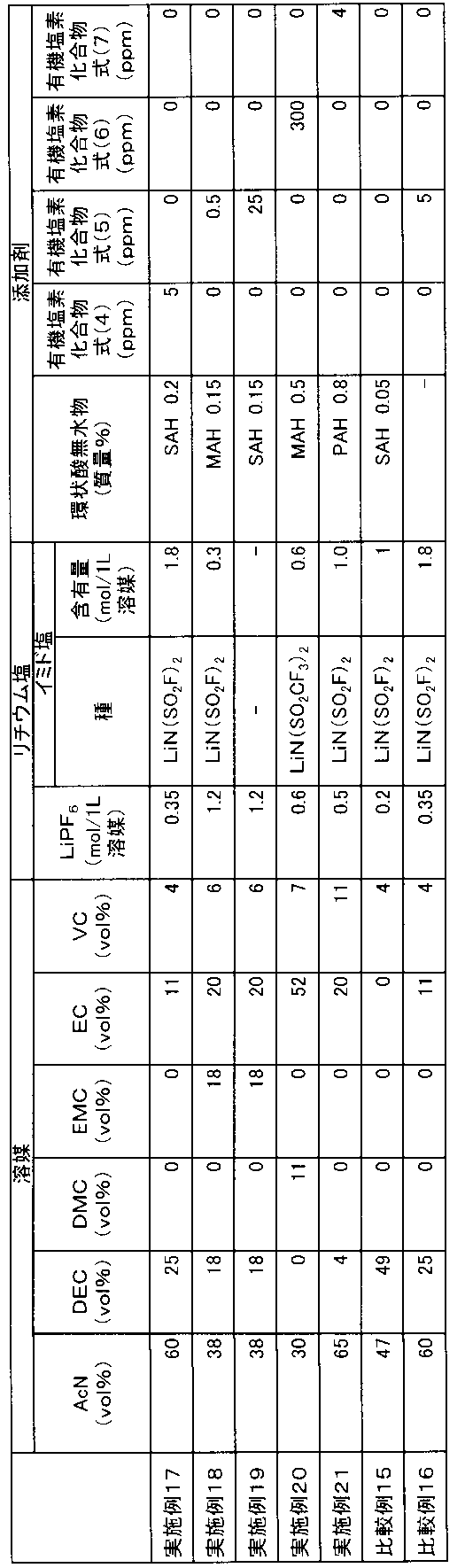





[電解液の調整]
各種溶媒及び添加剤を所定の体積比になるように混ぜることで電解液を調整した。実施例及び比較例で用いた各電解液の組成は表14に示した。なお、表14において「AcN」はアセトニトリル、「DEC」はジエチルカーボネート、「DMC」は、ジメチルカーボネート、「EMC」はエチルメチルカーボネート、「EC」はエチレンカーボネート、「VC」はビニレンカーボネート、「VC」は、ビニレンカーボネート、「LiPF6」はヘキサフルオロリン酸リチウム、「LiBOB」はリチウムビスオキサレートボレート(LiB(C2O4)2)、「LiN(SO2F)2」はリチウムビス(フルオロスルホニル)イミド、「SAH」は無水コハク酸、「MAH」は無水マレイン酸、「PAH」は無水フタル酸をそれぞれ示す。
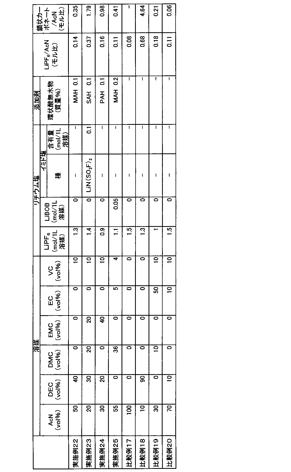
上記の調製した電解液を東陽テクニカ製の密閉セル(セルサイズ:24mmφ×0.35mmt)に入れて封入し、ホルダー(SH1-Z)にはめ込んで結線した。
得られたデータは、インピーダンスの実数成分(Z´)と虚数成分(Z´´)からなるナイキスト線図で表した。そして、Z´´=0におけるZ´値(R)を読み取って、以下の式によりLiイオン伝導度を求めた。
Liイオン伝導度(mS/cm)=d/(R・S)
ここで、dは、電極間距離(0.35cm)、Sは、電極面積(4.522cm2)である。
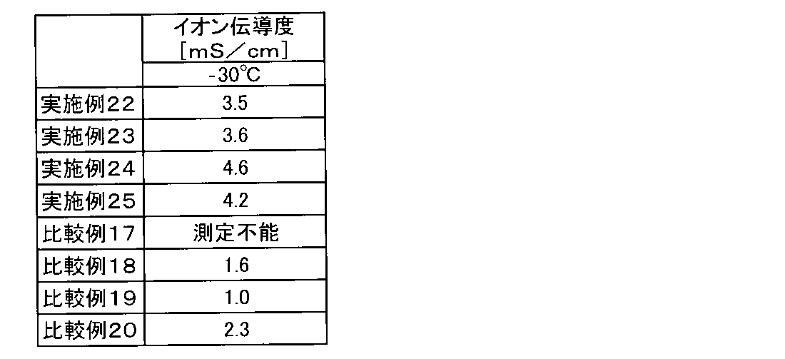
[電解液の調製]
各種溶媒及び添加剤を所定の体積比になるように混ぜることで電解液を調製した。実施例及び比較例で用いた各電解液の組成は表16に示した。なお、表16において「AcN」はアセトニトリル、「DEC」はジエチルカーボネート、「EMC」はエチルメチルカーボネート、「EC」はエチレンカーボネート、「VC」はビニレンカーボネート、「LiPF6」はヘキサフルオロリン酸リチウム、「(LiN(SO2F)2)」はリチウムビス(フルオロスルホニル)イミド、「SAH」は無水コハク酸、「PAH」は無水フタル酸をそれぞれ示す。

電解液を東陽テクニカ製の密閉セル(セルサイズ:24mmφ×0.35mmt)に入れて封入し、ホルダー(SH1-Z)にはめ込んで結線した。更に、恒温槽に入れて交流インピーダンス測定を行った。電極には金を使用した。電解液の採取から密閉セルへの充填、封入まではArグローブBOX内で行った。
Liイオン伝導度(mS/cm)=d/(R・S)
ここで、dは、電極間距離(0.35cm)、Sは、電極面積(4.522cm2)である。

次に、第21実施形態の実施例について以下説明する。
各種溶媒及び添加剤を所定の体積比になるように混ぜることで電解液を調製した。実施例及び比較例で用いた各電解液の組成は表18に示した。なお、表18において「AcN」はアセトニトリル、「DEC」はジエチルカーボネート、「DMC」はジメチルカーボネート、「EMC」はエチルメチルカーボネート、「EC」はエチレンカーボネート、「VC」はビニレンカーボネート、「LiPF6」はヘキサフルオロリン酸リチウム、「LiN(SO2F)2」はリチウムビス(フルオロスルホニル)イミド、「SAH」は無水コハク酸をそれぞれ示す。
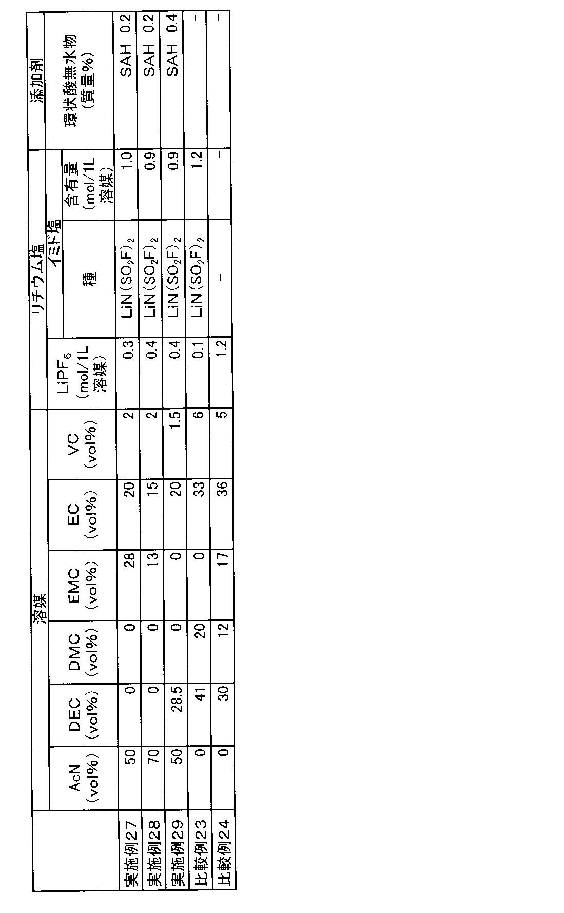
〔正極の作製〕
正極活物質としてリチウム、ニッケル、マンガン、及びコバルトの複合酸化物(LiNi0.5Mn0.3Co0.2O2)と、導電助剤としてアセチレンブラック粉末と、バインダーとしてポリフッ化ビニリデン(PVDF)とを、100:3.5:3の質量比で混合し、正極合剤を得た。得られた正極合剤に溶剤としてN-メチル-2-ピロリドンを投入して更に混合して、正極合剤含有スラリーを調製した。正極集電体となる厚さ15μmのアルミニウム箔片面に、この正極合剤含有スラリーを、目付量が約95.0g/m2になるように調節しながら塗布した。正極合剤含有スラリーをアルミニウム箔に塗布する際には、アルミニウム箔の一部が露出するように未塗布領域を形成した。その後、ロールプレスで正極活物質層の密度が2.74g/cm3になるように圧延することにより、正極活物質層と正極集電体とからなる正極を得た。
負極活物質である黒鉛と、バインダーであるカルボキシメチルセルロースと、同じくバインダーであるスチレンブタジエンラテックスとを、100:1.1:1.5の質量比で混合し、負極合剤を得た。得られた負極合剤に適量の水を添加した後に十分に混合して、負極合剤含有スラリーを調製した。このスラリーを、厚みが10μmの銅箔の片面に、目付量が約61.0g/m2になるように調節しながら一定厚みで塗布した。負極合剤含有スラリーを銅箔に塗布する際には、銅箔の一部が露出するように未塗布領域を形成した。その後、ロールプレスで負極活物質層の密度が1.20g/cm3になるように圧延することにより、負極活物質層と負極集電体とからなる負極を得た。
リード付き正極とリード付き負極とを、各極の合剤塗布面が対向するようにポリエチレン製微多孔膜セパレータ(厚み21μm)を介して重ね合わせて積層電極体とした。この積層電極体を、90mm×80mmのアルミニウムラミネートシート外装体内に収容し、水分を除去するために80℃で5時間真空乾燥を行った。続いて、上記した各電解液を外装体内に注入した後、外装体を封止することにより、単層ラミネート型(パウチ型)非水系二次電池(以下、単に「単層ラミネート電池」ともいう。)を作製した。この単層ラミネート電池は、設計容量値が23mAh、定格電圧値が4.2Vのものである。
上述のようにして得られた評価用電池について、まず、下記(1-1)の手順に従って初回充電処理を行った。次に(1-2)および(1-3)の手順に従ってそれぞれの電池を評価した。なお、充放電はアスカ電子(株)製の充放電装置ACD-01(商品名)及び二葉科学社製の恒温槽PLM-63S(商品名)を用いて行った。
電池の周囲温度を25℃に設定し、0.1Cに相当する2.3mAの定電流で充電して4.2Vに到達した後、4.2Vの定電圧で合計1.5時間充電を行った。その後、0.3Cに相当する6.9mAの定電流で2.5Vまで放電した。このときの放電容量を充電容量で割ることによって、初回効率を算出した。
上記(1-1)に記載の方法で初回充放電処理を行った電池について、交流インピーダンス測定を実施した。交流インピーダンス測定は、ソーラトロン社製周波数応答アナライザ1400(商品名)とソーラトロン社製ポテンショ-ガルバノスタット1470E(商品名)を用いた。1000kHz~0.01Hzに周波数を変えつつ交流信号を付与し、電圧・電流の応答信号からインピーダンスを測定し、複素インピーダンス平面プロット(cole-coleプロット)の横軸と交差した値をバルク抵抗、横軸と交差する円弧の直線長さ高周波数側の円弧の横幅にバルク抵抗値を足した値を界面抵抗として求めた。また、抵抗値はいずれも実数部(横軸)の値を使用した。印可する交流電圧の振幅は±5mVとした。また、交流インピーダンスを測定する際の電池の周囲温度は25℃とした。また、これらの結果から下記の表19に示す値を算出した。
上記(1-1)に記載の方法で初回充放電処理を行った電池について、サイクル試験を実施した。まず、電池の周囲温度を-10℃に設定し、0.2Cに相当する4.6mAの定電流で充電して4.2Vに到達した後、4.2Vの定電圧で合計3時間充電を行った。その後、4.6mAの定電流で2.5Vまで放電した。充電と放電とを各々1回ずつ行うこの工程を1サイクルとし、20サイクルの充放電を行った。1サイクル目の放電容量を100%としたときの20サイクル目の放電容量を容量維持率とした。

電解液を東陽テクニカ製の密閉セル(セルサイズ:24mmφ×0.35mmt)に入れて封入し、ホルダー(SH1-Z)にはめ込んで結線した。更に、恒温槽に入れて交流インピーダンス測定を行った。電極には金を使用した。電解液の採取から密閉セルへの充填、封入まではArグローブBOX内で行った。
Liイオン伝導度(mS/cm)=d/(R・S)
ここで、dは、電極間距離(0.35cm)、Sは、電極面積(4.522cm2)である。

各種溶媒及び添加剤を所定の体積比になるように混ぜることで電解液を調製した。実施例及び比較例で用いた各電解液の組成は表21に示した。なお、表21において「AcN」はアセトニトリル、「DEC」はジエチルカーボネート、「EMC」はエチルメチルカーボネート、「EC」はエチレンカーボネート、「VC」はビニレンカーボネート、「LiPF6」はヘキサフルオロリン酸リチウム、「LiBOB」はリチウムビスオキサレートボレート、「LiN(SO2F)2」はリチウムビス(フルオロスルホニル)イミド、「LiN(SO2CF3)2」はリチウムビス(トリフルオロメタンスルホニル)イミド、「SAH」は無水コハク酸、「MAH」は無水マレイン酸、「PAH」は無水フタル酸をそれぞれ示す。

〔正極の作製〕
正極活物質としてリチウム、ニッケル、マンガン、及びコバルトの複合酸化物(LiNi0.5Mn0.3Co0.2O2)と、導電助剤としてアセチレンブラック粉末と、バインダーとしてポリフッ化ビニリデン(PVDF)とを、100:3.5:3の質量比で混合し、正極合剤を得た。得られた正極合剤に溶剤としてN-メチル-2-ピロリドンを投入して更に混合して、正極合剤含有スラリーを調製した。正極集電体となる厚さ15μmのアルミニウム箔片面に、この正極合剤含有スラリーを、目付量が約95.0g/m2になるように調節しながら塗布した。正極合剤含有スラリーをアルミニウム箔に塗布する際には、アルミニウム箔の一部が露出するように未塗布領域を形成した。その後、ロールプレスで正極活物質層の密度が2.50g/cm3になるように圧延することにより、正極活物質層と正極集電体とからなる正極を得た。
負極活物質である黒鉛と、バインダーであるカルボキシメチルセルロースと、同じくバインダーであるスチレンブタジエンラテックスとを、100:1.1:1.5の質量比で混合し、負極合剤を得た。得られた負極合剤に適量の水を添加した後に十分に混合して、負極合剤含有スラリーを調製した。このスラリーを、厚みが10μmの銅箔の片面に、目付量が約61.0g/m2になるように調節しながら一定厚みで塗布した。負極合剤含有スラリーを銅箔に塗布する際には、銅箔の一部が露出するように未塗布領域を形成した。その後、ロールプレスで負極活物質層の密度が1.35g/cm3になるように圧延することにより、負極活物質層と負極集電体とからなる負極を得た。
リード付き正極とリード付き負極とを、各極の合剤塗布面が対向するようにポリエチレン製微多孔膜セパレータ(厚み21μm)を介して重ね合わせて積層電極体とした。この積層電極体を、90mm×80mmのアルミニウムラミネートシート外装体内に収容し、水分を除去するために80℃で5時間真空乾燥を行った。続いて、上記した各電解液を外装体内に注入した後、外装体を封止することにより、単層ラミネート型(パウチ型)非水系二次電池(以下、単に「単層ラミネート電池」ともいう。)を作製した。この単層ラミネート電池は、設計容量値が23mAh、定格電圧値が4.2Vのものである。
上述のようにして得られた単層ラミネート電池について、以下の手順に従って初回充放電処理を行った。続いて60℃における4.2V貯蔵特性を評価した。充放電は、アスカ電子(株)製の充放電装置ACD-01(商品名)及び二葉科学社製の恒温槽PLM-73S(商品名)を用いて行った。
単層ラミネート電池の周囲温度を25℃に設定し、0.05Cに相当する1.15mAの定電流で充電して電池電圧が4.2Vに到達するまで充電を行った後、4.2Vの定電圧で充電を継続し、3時間の充電を行った。その後、0.3Cに相当する6.9mAの定電流で3.0Vまで放電した。
上記初回充放電処理後の単層ラミネート電池について、25℃において、0.3Cの電流値で4.2Vになるまで定電流充電を行った後、4.2Vで1時間の定電圧充電を行った。そして、この充電後の単層ラミネート電池を60℃の恒温槽内で貯蔵した。200時間経過後、単層ラミネート電池を恒温槽から取り出して室温に戻した後に、各ラミネートセルのガス発生量と電圧を測定する手法により、単層ラミネート電池の4.2V貯蔵特性を評価した。ガス発生量は、超純水の入った容器に単層ラミネート電池を投入し、その前後での重量変化から単層ラミネート電池の体積を測定するというアルキメデス法を用いた。重量変化から体積を測定する装置としてはアルファーミラージュ社製の比重計MDS-300を用いた。
実施例、比較例とも表21に示した組成で電解液を作製し、上記の方法で正極及び負極を作製し、単層ラミネート電池を組み立ててその評価を行った。結果を表22に示す。
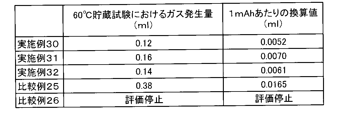
[非水系電池の作製]
(1-1) 正極の作製
正極活物質としてリチウム、ニッケル、マンガン、及びコバルトの複合酸化物(LiNi1/3Mn1/3Co1/3O2)と、導電助剤としてアセチレンブラック粉末と、バインダーとしてポリフッ化ビニリデン(PVDF)とを、86:8:6の質量比で混合し、正極合剤を得た。得られた正極合剤に溶剤としてN-メチル-2-ピロリドンを投入して更に混合して、正極合剤含有スラリーを調製した。この正極合剤含有スラリーを、正極集電体となるアルミニウム箔両面に、片面あたりの目付量が11.5mg/cm2になるように調節しながら塗布した。正極合剤含有スラリーをアルミニウム箔に塗布する際には、アルミニウム箔の一部が露出するように未塗布領域を形成した。その後、ロールプレスで合材層の密度が2.8mg/cm3になるように圧延することにより、正極活物質層と正極集電体とからなる正極を得た。
負極活物質であるグラファイトと、導電助剤であるアセチレンブラックと、バインダーであるPVDFとを86:7:7の質量比で混合し、負極合剤を得た。得られた負極合剤に適量の水を添加した後に十分に混合して、負極合剤含有スラリーを調製した。この負極合剤含有スラリーを、銅箔の両面に、片面あたりの目付量が6.9mg/cm2になるように調節しながら塗布した。負極合剤含有スラリーを銅箔に塗布する際には、銅箔の一部が露出するように未塗布領域を形成した。その後、ロールプレスで合材層の密度が1.3mg/cm3になるように圧延することにより、負極活物質層と負極集電体とからなる負極を得た。
リード付き正極とリード付き負極とを、各極の合剤塗布面が対向するようにポリエチレン製樹脂フィルムを介して重ね合わせて積層電極体とした。この積層電極体をアルミニウムラミネートシート外装体内に収容し、水分を除去するために80℃で5h真空乾燥を行った。続いて、電解液を外装体内に注入した後、外装体を封止することにより、積層ラミネート型非水系二次電池(パウチ型セル電池。以下、単に「積層ラミネート電池」ともいう。)を作製した。正極端子と負極端子の無い融着辺に、安全弁機構となる穴を形成した。穴の周囲を同心円形状にて熱融着した。
上述のようにして得られた積層ラミネート電池について、以下の手順に従って初回充放電処理を行った。続いて2C過充電試験を実施した。ここで、1Cとは満充電状態の電池を、定電流で放電して1時間で放電終了となることが期待される電流値を意味する。下記においては、4.2Vの満充電状態から定電流で3.0Vまで放電して1時間で放電終了となることが期待される電流値を意味する。
充電装置は菊水電子工業製バッテリテスタPFX2011を使用した。積層ラミネート電池の周囲温度を25℃に設定し、0.2Cの電流値で4.2Vまで定電流充電を行った後、4.2Vで1時間の定電圧充電を行った。その後、0.2Cに相当する定電流で2.7Vになるまで放電した。その後、露点-60℃以下に制御されたグローブボックス内にて、電池の封止部を開口しガス抜きを行った。ガス抜き後、同じ環境下において真空シールを行った。
上記の初回充放電処理後の積層ラミネート電池を、25℃において、0.2Cの電流値で4.2Vまで定電流充電し、その後4.2Vで1時間、定電圧充電した。満充電状態にまで充電した電池に対して、下記の如く過充電試験を行った。電源は菊水電子工業製直流電源PAT60-133Tを使用し、室温(25±5℃)、2C相当の定電流、60Vの定電圧とした。試験中の電流、電圧、各部位及び雰囲気の温度は日置電機製メモリハイロガーLR8400によって100ms毎に記録した。同時に、電池外観もビデオによって観察・記録した。
下記の表23に示す各種溶媒及び添加剤を所定量混ぜることで電解液を調製した。すなわち、アセトニトリル(AcN)と、ジエチルカーボネート(DEC)と、ビニレンカーボネート(VC)と、エチレンカーボネート(EC)と、の体積比が47:28:4:21となるように加えて混合した。さらにこの混合液における非水系溶媒1Lあたりヘキサフルオロリン酸リチウム(LiPF6)を0.3mol、リチウムビス(フルオロスルホニル)イミド(LiN(SO2F)2)を1.0mol添加した。また、非水系電解液に、無水コハク酸(SAH)を1質量%、プロピオニトリル(PrN)を11ppm(質量比)、酢酸(AA)を0.2ppm(質量比)添加して、実施例33の電解液を得た。この電解液について上記(1-3)に記載の方法で電池作製した後、上記(2-1)~(2-2)に記載の手順で、積層ラミネート電池の評価を行った。
下記の表23に示す各種溶媒及び添加剤を所定量混ぜることで電解液を調製した。すなわち、アセトニトリル(AcN)と、ジエチルカーボネート(DEC)と、ビニレンカーボネート(VC)と、エチレンカーボネート(EC)と、の体積比が47:28:4:21となるように加えて混合した。さらにこの混合液における非水系溶媒1Lあたりヘキサフルオロリン酸リチウム(LiPF6)を0.3mol、リチウムビス(フルオロスルホニル)イミド(LiN(SO2F)2)を1.0mol添加した。また、非水系電解液に対し、無水コハク酸(SAH)を1質量%、プロピオニトリル(PrN)を125ppm(質量比)、酢酸(AA)を1.0ppm(質量比)添加して、実施例34の電解液を得た。この電解液について上記(1-3)に記載の方法で電池作製した後、上記(2-1)~(2-2)に記載の手順で、積層ラミネート電池の評価を行った。
下記の表23に示す各種溶媒及び添加剤を所定量混ぜることで電解液を調製した。すなわち、アセトニトリル(AcN)と、ジエチルカーボネート(DEC)と、ビニレンカーボネート(VC)と、エチレンカーボネート(EC)と、の体積比が47:28:4:21となるように加えて混合した。さらにこの混合液における非水系溶媒1Lあたりヘキサフルオロリン酸リチウム(LiPF6)を1.3mol添加した。また、非水系電解液に対し、無水コハク酸(SAH)を1質量%、プロピオニトリル(PrN)を10ppm(質量比)、酢酸(AA)を0.4ppm(質量比)添加して、実施例35の電解液を得た。この電解液について上記(1-3)に記載の方法で電池作製した後、上記(2-1)~(2-2)に記載の手順で、積層ラミネート電池の評価を行った。
下記の表23に示す各種溶媒及び添加剤を所定量混ぜることで電解液を調製した。すなわち、アセトニトリル(AcN)と、ジエチルカーボネート(DEC)と、ビニレンカーボネート(VC)と、エチレンカーボネート(EC)と、の体積比が47:28:4:21となるように加えて混合した。さらにこの混合液における非水系溶媒1Lあたりヘキサフルオロリン酸リチウム(LiPF6)を1.3mol添加した。また、非水系電解液に対し、無水コハク酸(SAH)を1質量%、プロピオニトリル(PrN)を90ppm(質量比)、酢酸(AA)を2.5ppm(質量比)添加して、実施例36の電解液を得た。この電解液について上記(1-3)に記載の方法で電池作製した後、上記(2-1)~(2-2)に記載の手順で、積層ラミネート電池の評価を行った。
下記の表23に示す各種溶媒及び添加剤を所定量混ぜることで電解液を調製した。すなわち、アセトニトリル(AcN)と、ジエチルカーボネート(DEC)と、ビニレンカーボネート(VC)と、エチレンカーボネート(EC)と、の体積比が47:28:4:21となるように加えて混合した。さらにこの混合液における非水系溶媒1Lあたりヘキサフルオロリン酸リチウム(LiPF6)を1.3mol添加した。また、非水系電解液に対し、無水コハク酸(SAH)を1質量%添加して、比較例27の電解液を得た。なお、比較例27には、酢酸及びプロピオニトリルを添加していない。この電解液について上記(1-3)に記載の方法で電池作製した後、上記(2-1)~(2-2)に記載の手順で、積層ラミネート電池の評価を行った。
下記の表23に示す各種溶媒及び添加剤を所定量混ぜることで電解液を調製した。すなわち、アセトニトリル(AcN)と、ジエチルカーボネート(DEC)と、ビニレンカーボネート(VC)と、エチレンカーボネート(EC)と、の体積比が47:28:4:21となるように加えて混合した。さらにこの混合液における非水系溶媒1Lあたりヘキサフルオロリン酸リチウム(LiPF6)を0.3mol、リチウムビス(フルオロスルホニル)イミド(LiN(SO2F)2)を1.0mol添加した。また、非水系電解液に対し、無水コハク酸(SAH)を1質量%、プロピオニトリルを105ppm添加して、比較例28の電解液を得た。なお、比較例28には、酢酸を添加していない。この電解液について上記(1-3)に記載の方法で電池作製した後、上記(2-1)~(2-2)に記載の手順で、積層ラミネート電池の評価を行った。
下記の表23に示す各種溶媒及び添加剤を所定量混ぜることで電解液を調製した。すなわち、アセトニトリル(AcN)と、ジエチルカーボネート(DEC)と、ビニレンカーボネート(VC)と、エチレンカーボネート(EC)と、の体積比が47:28:4:21となるように加えて混合した。さらにこの混合液における非水系溶媒1Lあたりヘキサフルオロリン酸リチウム(LiPF6)を1.3mol添加した。また、非水系電解液に対し、無水コハク酸(SAH)を1質量%、プロピオニトリル(PrN)を500ppm(質量比)、酢酸(AA)を100ppm(質量比)添加して、比較例29の電解液を得た。この電解液について上記(1-3)に記載の方法で電池作製した後、上記(2-1)~(2-2)に記載の手順で、積層ラミネート電池の評価を行った。
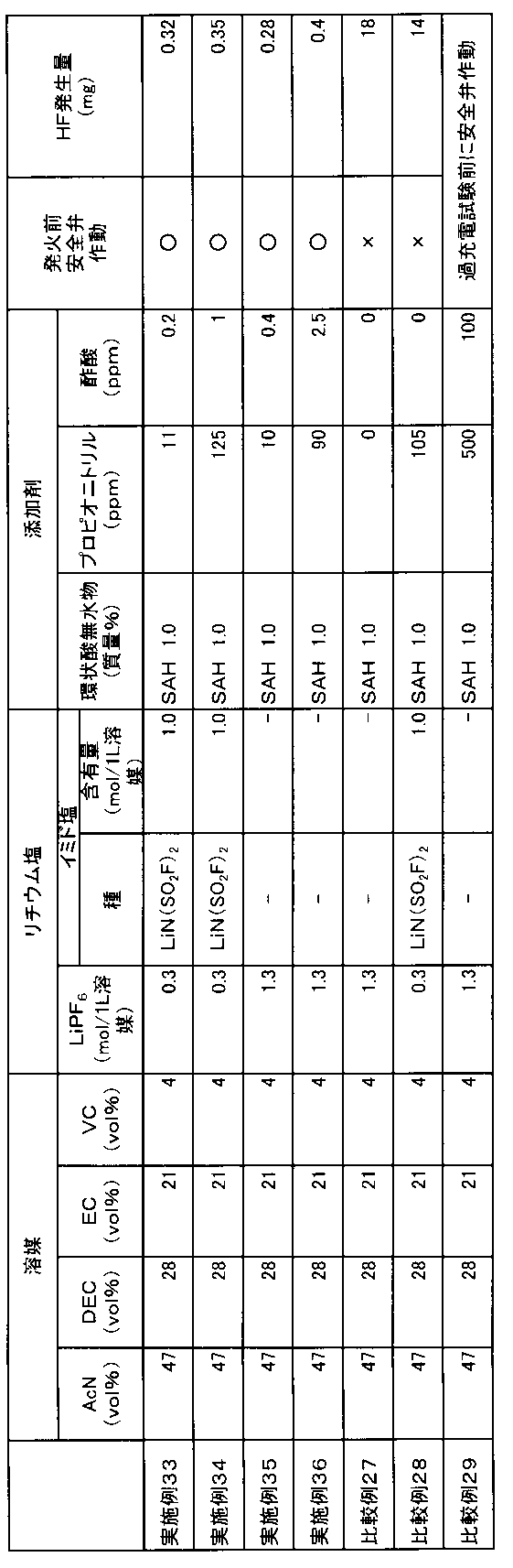
(1-1) 正極の作製
正極活物質としてリチウム、ニッケル、マンガン、及びコバルトの複合酸化物(LiNi1/3Mn1/3Co1/3O2)と、導電助剤としてアセチレンブラック粉末と、バインダーとしてポリフッ化ビニリデン(PVDF)とを、86:8:6の質量比で混合し、正極合剤を得た。得られた正極合剤に溶剤としてN-メチル-2-ピロリドンを投入して更に混合して、正極合剤含有スラリーを調製した。この正極合剤含有スラリーを、正極集電体となるアルミニウム箔両面に、片面あたりの目付量が11.5mg/cm2になるように調節しながら塗布した。正極合剤含有スラリーをアルミニウム箔に塗布する際には、アルミニウム箔の一部が露出するように未塗布領域を形成した。その後、ロールプレスで合材層の密度が2.8mg/cm3になるように圧延することにより、正極活物質層と正極集電体とからなる正極を得た。
負極活物質であるグラファイトと、導電助剤であるアセチレンブラックと、バインダーであるPVDFとを86:7:7の質量比で混合し、負極合剤を得た。得られた負極合剤に適量の水を添加した後に十分に混合して、負極合剤含有スラリーを調製した。この負極合剤含有スラリーを、銅箔の両面に、片面あたりの目付量が6.9mg/cm2になるように調節しながら塗布した。負極合剤含有スラリーを銅箔に塗布する際には、銅箔の一部が露出するように未塗布領域を形成した。その後、ロールプレスで合材層の密度が1.3mg/cm3になるように圧延することにより、負極活物質層と負極集電体とからなる負極を得た。
リード付き正極とリード付き負極とを、各極の合剤塗布面が対向するようにポリエチレン製樹脂フィルムを介して重ね合わせて積層電極体とした。この積層電極体をアルミニウムラミネートシート外装体内に収容し、水分を除去するために80℃で5h真空乾燥を行った。続いて、電解液を外装体内に注入した後、外装体を封止することにより、積層ラミネート型非水系二次電池(パウチ型セル電池。以下、単に「積層ラミネート電池」ともいう。)を作製した。正極端子と負極端子の無い融着辺に、安全弁機構となる穴を形成した。穴の周囲を同心円形状にて熱融着した。
上述のようにして得られた積層ラミネート電池について、以下の手順に従って初回充放電処理を行った。続いて2C過充電試験を実施した。ここで、1Cとは満充電状態の電池を、定電流で放電して1時間で放電終了となることが期待される電流値を意味する。下記においては、4.2Vの満充電状態から定電流で3.0Vまで放電して1時間で放電終了となることが期待される電流値を意味する。
充電装置は菊水電子工業製バッテリテスタPFX2011を使用した。積層ラミネート電池の周囲温度を25℃に設定し、0.2Cの電流値で4.2Vまで定電流充電を行った後、4.2Vで1時間の定電圧充電を行った。その後、0.2Cに相当する定電流で2.7Vになるまで放電した。その後、露点-60℃以下に制御されたグローブボックス内にて、電池の封止部を開口しガス抜きを行った。ガス抜き後、同じ環境下において真空シールを行った。
上記の初回充放電処理後の積層ラミネート電池を、25℃において、0.2Cの電流値で4.2Vまで定電流充電し、その後4.2Vで1時間、定電圧充電した。満充電状態にまで充電した電池に対して、下記の如く過充電試験を行った。電源は菊水電子工業製直流電源PAT60-133Tを使用し、室温(25±5℃)、2C相当の定電流、60Vの定電圧とした。試験中の電流、電圧、各部位及び雰囲気の温度は日置電機製メモリハイロガーLR8400によって100ms毎に記録した。同時に、電池外観もビデオによって観察・記録した。
下記の表24に示す各種溶媒及び添加剤を所定量混ぜることで電解液を調製した。すなわち、アセトニトリル(AcN)と、ジエチルカーボネート(DEC)と、ビニレンカーボネート(VC)と、エチレンカーボネート(EC)と、の体積比が47:28:4:21となるように加えて混合した。さらにこの混合液における非水系溶媒1Lあたりヘキサフルオロリン酸リチウム(LiPF6)を0.3mol、リチウムビス(フルオロスルホニル)イミド(LiN(SO2F)2)を、1.0mol添加した。また、非水系電解液に、無水コハク酸(SAH)を、0.7質量%、アセトアルデヒド(AcA)を52ppm、及び遷移金属ニトリル錯体(MC)を、4008ppm添加した。このように、添加剤としてのアセトアルデヒドと、遷移金属のニトリル錯体の添加量は、電解質を溶解した電解液に対する重量割合(ppm)で示した。
下記の表24に示す各種溶媒及び添加剤を所定量混ぜることで電解液を調製した。すなわち、アセトニトリル(AcN)と、ジエチルカーボネート(DEC)と、ビニレンカーボネート(VC)と、エチレンカーボネート(EC)と、の体積比が47:28:4:21となるように加えて混合した。さらにこの混合液における非水系溶媒1Lあたりヘキサフルオロリン酸リチウム(LiPF6)を0.3mol、リチウムビス(フルオロスルホニル)イミド(LiN(SO2F)2)を、1.0mol添加した。また、非水系電解液に対し、無水コハク酸(SAH)を0.7質量%、アセトアルデヒド(AcA)を1595ppm、及び遷移金属ニトリル錯体(MC)を、2190ppm添加した。このようにして得た実施例38の電解液を備えた積層ラミネート電池について、上記(2-1)~(2-2)に記載の手順で、積層ラミネート電池の評価を行った。
下記の表24に示す各種溶媒及び添加剤を所定量混ぜることで電解液を調製した。すなわち、アセトニトリル(AcN)と、ジエチルカーボネート(DEC)と、ビニレンカーボネート(VC)と、エチレンカーボネート(EC)と、の体積比が47:28:4:21となるように加えて混合した。さらにこの混合液における非水系溶媒1Lあたりヘキサフルオロリン酸リチウム(LiPF6)を1.3mol添加した。また、非水系電解液に対し、無水コハク酸(SAH)を0.7質量%、アセトアルデヒド(AcA)を93ppm、及び遷移金属ニトリル錯体(MC)を、2922ppm添加した。このようにして得た実施例39の電解液を備えた積層ラミネート電池について、上記(2-1)~(2-2)に記載の手順で、積層ラミネート電池の評価を行った。
下記の表24に示す各種溶媒及び添加剤を所定量混ぜることで電解液を調製した。すなわち、アセトニトリル(AcN)と、ジエチルカーボネート(DEC)と、ビニレンカーボネート(VC)と、エチレンカーボネート(EC)と、の体積比が47:28:4:21となるように加えて混合した。さらにこの混合液における非水系溶媒1Lあたりヘキサフルオロリン酸リチウム(LiPF6)を1.3mol添加した。また、非水系電解液に対し、無水コハク酸(SAH)を0.7質量%、アセトアルデヒド(AcA)を1610ppm、及び遷移金属ニトリル錯体(MC)を、1822ppm添加した。このようにして得た実施例40の電解液を備えた積層ラミネート電池について、上記(2-1)~(2-2)に記載の手順で、積層ラミネート電池の評価を行った。
下記の表24に示す各種溶媒及び添加剤を所定量混ぜることで電解液を調製した。すなわち、アセトニトリル(AcN)と、ジエチルカーボネート(DEC)と、ビニレンカーボネート(VC)と、エチレンカーボネート(EC)と、の体積比が47:28:4:21となるように加えて混合した。さらにこの混合液における非水系溶媒1Lあたりヘキサフルオロリン酸リチウム(LiPF6)を0.3mol、リチウムビス(フルオロスルホニル)イミド(LiN(SO2F)2)を、1.0mol添加した。比較例30では、無水コハク酸(SAH)、アセトアルデヒド(AcA)及び、遷移金属ニトリル錯体(MC)を添加していない。このようにして得た比較例30の電解液を備えた積層ラミネート電池について、上記(2-1)~(2-2)に記載の手順で、積層ラミネート電池の評価を行った。
下記の表24に示す各種溶媒及び添加剤を所定量混ぜることで電解液を調製した。すなわち、アセトニトリル(AcN)と、ジエチルカーボネート(DEC)と、ビニレンカーボネート(VC)と、エチレンカーボネート(EC)と、の体積比が47:28:4:21となるように加えて混合した。さらにこの混合液における非水系溶媒1Lあたりヘキサフルオロリン酸リチウム(LiPF6)を1.3mol、リチウムビス(フルオロスルホニル)イミド(LiN(SO2F)2)を、1.0mol添加した。また、非水系電解液に、無水コハク酸(SAH)を、0.7質量%添加した。比較例31では、アセトアルデヒド(AcA)及び、遷移金属ニトリル錯体(MC)を添加していない。このようにして得た比較例31の電解液を備えた積層ラミネート電池について、上記(2-1)~(2-2)に記載の手順で、積層ラミネート電池の評価を行った。
下記の表24に示す各種溶媒及び添加剤を所定量混ぜることで電解液を調製した。すなわち、アセトニトリル(AcN)と、ジエチルカーボネート(DEC)と、ビニレンカーボネート(VC)と、エチレンカーボネート(EC)と、の体積比が47:28:4:21となるように加えて混合した。さらにこの混合液における非水系溶媒1Lあたりヘキサフルオロリン酸リチウム(LiPF6)を1.3mol、リチウムビス(フルオロスルホニル)イミド(LiN(SO2F)2)を、1.0mol添加した。また、非水系電解液に、無水コハク酸(SAH)を、0.7質量%添加した。比較例32では、アセトアルデヒド(AcA)を添加していない。このようにして得た比較例32の電解液を備えた積層ラミネート電池について、上記(2-1)~(2-2)に記載の手順で、積層ラミネート電池の評価を行った。
下記の表24に示す各種溶媒及び添加剤を所定量混ぜることで電解液を調製した。すなわち、アセトニトリル(AcN)と、ジエチルカーボネート(DEC)と、ビニレンカーボネート(VC)と、エチレンカーボネート(EC)と、の体積比が47:28:4:21となるように加えて混合した。さらにこの混合液における非水系溶媒1Lあたりヘキサフルオロリン酸リチウム(LiPF6)を1.3mol添加した。また、非水系電解液に、無水コハク酸(SAH)を、0.7質量%、アセトアルデヒド(AcA)を75ppm添加した。比較例33では、遷移金属ニトリル錯体(MC)を添加していない。このようにして得た比較例33の電解液を備えた積層ラミネート電池について、上記(2-1)~(2-2)に記載の手順で、積層ラミネート電池の評価を行った。
下記の表24に示す各種溶媒及び添加剤を所定量混ぜることで電解液を調製した。すなわち、アセトニトリル(AcN)と、ジエチルカーボネート(DEC)と、ビニレンカーボネート(VC)と、エチレンカーボネート(EC)と、の体積比が47:28:4:21となるように加えて混合した。さらにこの混合液における非水系溶媒1Lあたりヘキサフルオロリン酸リチウム(LiPF6)を1.3mol添加した。また、非水系電解液に、アセトアルデヒド(AcA)を82ppm、及び遷移金属ニトリル錯体(MC)を、3003ppm添加した。比較例34では、無水コハク酸(SAH)を添加していない。このようにして得た比較例34の電解液を備えた積層ラミネート電池について、上記(2-1)~(2-2)に記載の手順で、積層ラミネート電池の評価を行った。
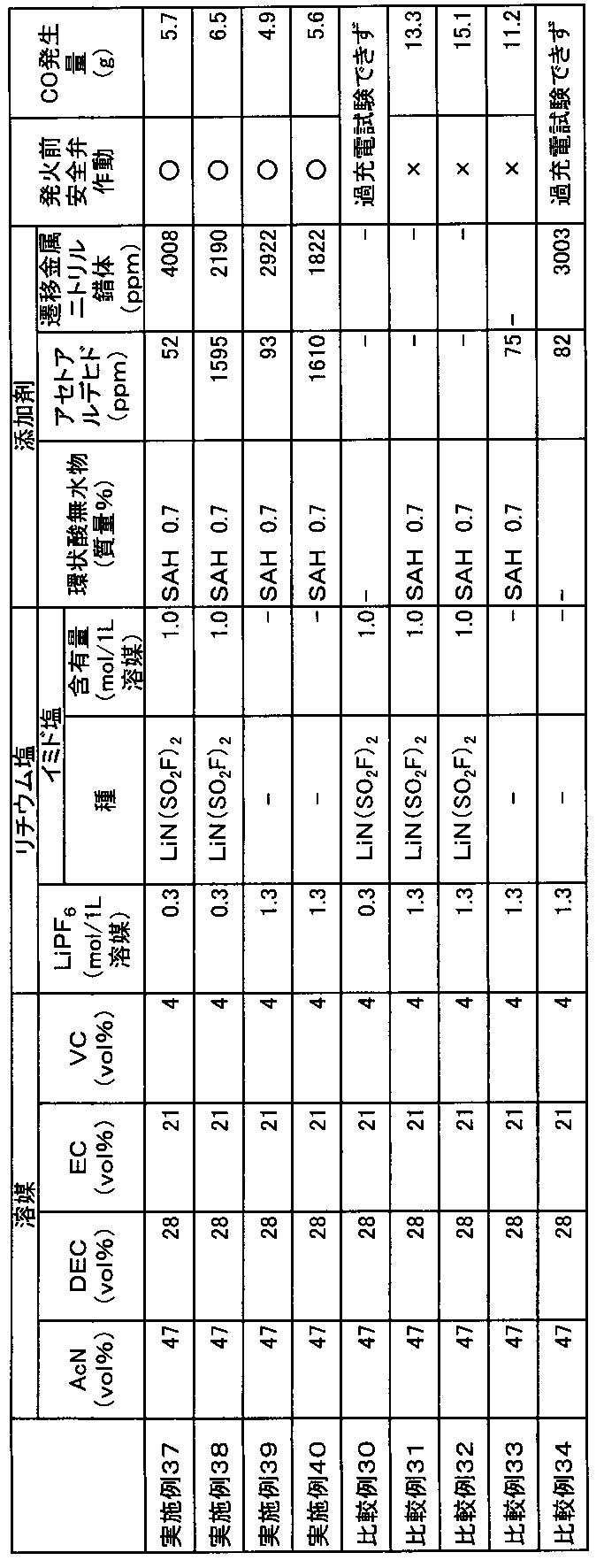
(1-1)正極の作製
正極活物質として数平均粒子径11μmのリチウムとニッケル、マンガン及びコバルトとの複合酸化物(Ni/Mn/Co=1/1/1(元素比);密度4.70g/cm3)と、導電助剤として数平均粒子径6.5μmのグラファイト炭素粉末(密度2.26g/cm3)及び数平均粒子径48nmのアセチレンブラック粉末(密度1.95g/cm3)と、バインダーとしてポリフッ化ビニリデン(PVdF;密度1.75g/cm3)とを、100:4.2:1.8:4.6の質量比で混合し、正極合剤を得た。得られた正極合剤に溶剤としてN-メチル-2-ピロリドンを固形分68質量%となるように投入して更に混合して、正極合剤含有スラリーを調製した。正極集電体となる厚さ20μm、幅200mmのアルミニウム箔の片面に、この正極合剤含有スラリーを目付量が12.0mg/cm2になるように調節しながらドクターブレード法で塗布し、溶剤を乾燥除去した。その後、ロールプレスで実電極密度が2.80g/cm3になるよう圧延して、正極活物質層と正極集電体からなる正極を得た。
負極活物質として数平均粒子径12.7μmのグラファイト炭素粉末(密度2.23g/cm3)及び数平均粒子径6.5μmのグラファイト炭素粉末(密度2.27g/cm3)と、バインダーとしてカルボキシメチルセルロース(密度1.60g/cm3)溶液(固形分濃度1.83質量%)と、ジエン系ゴム(ガラス転移温度:-5℃、乾燥時の数平均粒子径:120nm、密度1.00g/cm3、分散媒:水、固形分濃度40質量%)とを、87.2:9.7:1.4:1.7の固形分質量比で混合し、負極合剤を得た。得られた負極合剤に溶剤として水を固形分45質量%となるように投入して更に混合して、負極合剤含有スラリーを調製した。負極集電体となる厚さ10μm、幅200mmの銅箔の片面に、この負極合剤含有スラリーを目付量が5.3mg/cm2になるよう調節しながらドクターブレード法で塗布し、溶剤を乾燥除去した。その後、ロールプレスで実電極密度が1.30g/cm3になるよう圧延して、負極活物質層と負極集電体からなる負極を得た。
CR2032タイプの電池ケース(SUS304/Alクラッド)にポリプロピレン製ガスケットをセットし、その中央に上述のようにして得られた正極を直径16mmの円盤状に打ち抜いたものを、正極活物質層を上向きにしてセットした。その上からガラス繊維濾紙(アドバンテック社製ガラス繊維濾紙 GA-100)を直径16mmの円盤状に打ち抜いたものをセットして、電解液を150μL注入した後、上述のようにして得られた負極を直径16mmの円盤状に打ち抜いたものを、負極活物質層を下向きにしてセットした。さらにスペーサーとスプリングをセットした後に電池キャップをはめ込み、カシメ機でかしめた。あふれた電解液はウエスできれいにふきとった。25℃で24時間保持し、積層体に電解液を十分馴染ませてコイン型非水系二次電池を得た。
上述のようにして得られた評価用電池について、まず、下記(2-1)の手順に従って初回充電処理を行った。次に(2-2)の手順に従ってそれぞれの電池を評価した。なお、充放電はアスカ電子(株)製の充放電装置ACD-01(商品名)及び二葉科学社製の恒温槽PLM-63S(商品名)を用いて行った。
電池の周囲温度を25℃に設定し、0.1Cに相当する0.3mAの定電流で充電して4.2Vに到達した後、4.2Vの定電圧で合計15時間充電を行った。その後、0.3Cに相当する0.9mAの定電流で3.0Vまで放電した。このときの放電容量を充電容量で割ることによって、初回効率を算出した。
上記(2-1)に記載の方法で初回充放電処理を行った電池について、サイクル試験を実施した。まず、電池の周囲温度を25℃に設定し、1Cに相当する3mAの定電流で充電して4.2Vに到達した後、4.2Vの定電圧で合計3時間充電を行った。その後、3mAの定電流で3Vまで放電した。充電と放電とを各々1回ずつ行うこの工程を1サイクルとし、100サイクルの充放電を行った。1サイクル目の放電容量を100%としたときの100サイクル目の放電容量を容量維持率とした。
交流インピーダンス測定は、ソーラトロン社製周波数応答アナライザ1400(商品名)とソーラトロン社製ポテンショ-ガルバノスタット1470E(商品名)を用いた。1000kHz~0.01Hzに周波数を変えつつ交流信号を付与し、電圧・電流の応答信号からインピーダンスを測定し、1kHzにおける交流インピーダンス値を求めた。印可する交流電圧の振幅は±5mVとした。また、交流インピーダンスを測定する際の電池の周囲温度は25℃とした。また、これらの結果から下記の値を算出した。
不活性雰囲気下、アセトニトリル(AcN)とジエチルカーボネート(DEC)と、エチレンカーボネート(EC)とビニレンカーボネート(VC)の体積比が44:25:26:5となるよう混合した。更に、この混合液1Lあたり0.25molのヘキサフルオロリン酸リチウム(LiPF6)と1.25molのリチウムビス(フルオロスルホニル)イミド(LiN(SO2F)2)を溶解させ、さらに2,6-ジ-tert-ブチル-p-クレゾール(BHT)を4ppm、環状酸無水物としての無水コハク酸を0.2質量%加えて混合し、実施例41の電解液を得た。得られた電解液について、目視でリチウム塩、BHTおよび環状酸無水物が全て溶解していることを確認した。この電解液について上記(1-3)に記載の方法で電池作製した後、上記(2-1)~(2-3)に記載の手順で測定を行った。
不活性雰囲気下、アセトニトリル(AcN)とエチルメチルカーボネート(EMC)と、エチレンカーボネート(EC)とビニレンカーボネート(VC)の体積比が35:40:21:4となるよう混合した。更に、この混合液1Lあたり0.6molのヘキサフルオロリン酸リチウム(LiPF6)と0.6molのリチウムビス(フルオロスルホニル)イミド(LiN(SO2F)2)を溶解させ、さらに2,6-ジ-tert-ブチル-p-クレゾール(BHT)を1ppm、環状酸無水物としての無水マレイン酸を0.15質量%加えて混合し、実施例42の電解液を得た。得られた電解液について、目視でリチウム塩、BHTおよび環状酸無水物が全て溶解していることを確認した。この電解液について上記(1-3)に記載の方法で電池作製した後、上記(2-1)~(2-3)に記載の手順で測定を行った。
不活性雰囲気下、アセトニトリル(AcN)とジエチルカーボネート(DEC)と、エチレンカーボネート(EC)とビニレンカーボネート(VC)の体積比が45:13:25:17となるよう混合した。更に、この混合液1Lあたり0.5molのヘキサフルオロリン酸リチウム(LiPF6)と1.5molのリチウムビス(トリフルオロメタンスルホニル)イミド(LiN(SO2CF3)2)を溶解させ、さらに2,6-ジ-tert-ブチル-p-クレゾール(BHT)を15ppm、環状酸無水物としての無水フタル酸を0.5質量%加えて混合し、実施例43の電解液を得た。得られた電解液について、目視でリチウム塩、BHTおよび環状酸無水物が全て溶解していることを確認した。この電解液について上記(1-3)に記載の方法で電池作製した後、上記(2-1)~(2-3)に記載の手順で測定を行った。
不活性雰囲気下、アセトニトリル(AcN)とプロピレンカーボネート(PC)とビニレンカーボネート(VC)の体積比が60:32:8となるよう混合した。更に、この混合液1Lあたり1.0molのヘキサフルオロリン酸リチウム(LiPF6)と0.1molのリチウムビス(フルオロスルホニル)イミド(LiN(SO2F)2)を溶解させ、さらに環状酸無水物としての無水マレイン酸を0.07質量%加えて混合し、比較例35の電解液を得た。この電解液にはBHTを添加していない。得られた電解液について、目視でリチウム塩及び環状酸無水物が全て溶解していることを確認した。この電解液について上記(1-3)に記載の方法で電池作製した後、上記(2-1)~(2-3)に記載の手順で測定を行った。
不活性雰囲気下、アセトニトリル(AcN)とジエチルカーボネート(DEC)とビニレンカーボネート(VC)の体積比が85:11:4となるよう混合した。更に、この混合液1Lあたり1.1molのヘキサフルオロリン酸リチウム(LiPF6)を溶解させ、さらに2,6-ジ-tert-ブチル-p-クレゾール(BHT)を5ppm加えて混合し、比較例36の電解液を得た。なお、この電解液には環状酸無水物を添加していない。得られた電解液について、目視でリチウム塩及びBHTが全て溶解していることを確認した。この電解液について上記(1-3)に記載の方法で電池作製した後、上記(2-1)~(2-3)に記載の手順で測定を行った。

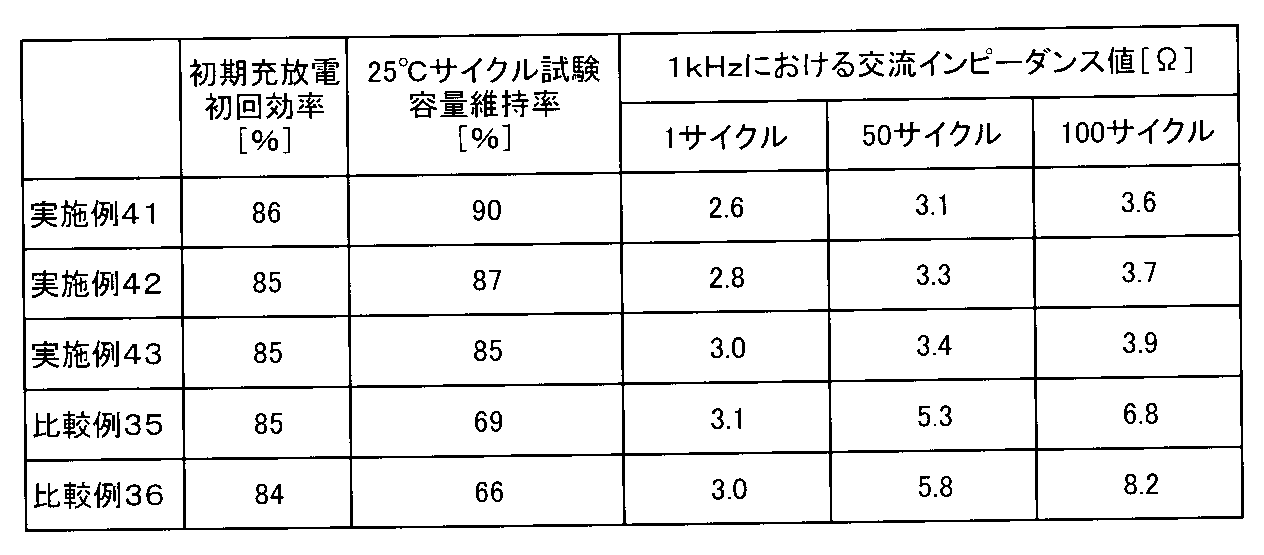
各種溶媒及び添加剤を所定の体積比になるように混ぜることで電解液を調製した。実施例及び比較例で用いた各電解液の組成は表27に示した。なお、表27において「AcN」はアセトニトリル、「DEC」はジエチルカーボネート、「EC」はエチレンカーボネート、「VC」はビニレンカーボネート、「LiPF6」はヘキサフルオロリン酸リチウム、「LiN(SO2F)2」はリチウムビス(フルオロスルホニル)イミド、「MBTA」は、1-メチル-1H-ベンゾトリアゾール、「SAH」は無水コハク酸をそれぞれ示す。

〔正極の作製〕
正極活物質としてリチウム、ニッケル、マンガン、及びコバルトの複合酸化物(LiNi0.5Mn0.3Co0.2O2)と、導電助剤としてアセチレンブラック粉末と、バインダーとしてポリフッ化ビニリデン(PVDF)とを、100:3.5:3の質量比で混合し、正極合剤を得た。得られた正極合剤に溶剤としてN-メチル-2-ピロリドンを投入して更に混合して、正極合剤含有スラリーを調製した。正極集電体となる厚さ15μmのアルミニウム箔片面に、この正極合剤含有スラリーを、目付量が約95.0g/m2になるように調節しながら塗布した。正極合剤含有スラリーをアルミニウム箔に塗布する際には、アルミニウム箔の一部が露出するように未塗布領域を形成した。その後、ロールプレスで正極活物質層の密度が2.50g/cm3になるように圧延することにより、正極活物質層と正極集電体とからなる正極を得た。
負極活物質である黒鉛と、バインダーであるカルボキシメチルセルロースと、同じくバインダーであるスチレンブタジエンラテックスとを、100:1.1:1.5の質量比で混合し、負極合剤を得た。得られた負極合剤に適量の水を添加した後に十分に混合して、負極合剤含有スラリーを調製した。このスラリーを、厚みが10μmの銅箔の片面に、目付量が約61.0g/m2になるように調節しながら一定厚みで塗布した。負極合剤含有スラリーを銅箔に塗布する際には、銅箔の一部が露出するように未塗布領域を形成した。その後、ロールプレスで負極活物質層の密度が1.35g/cm3になるように圧延することにより、負極活物質層と負極集電体とからなる負極を得た。
リード付き正極とリード付き負極とを、各極の合剤塗布面が対向するようにポリエチレン製微多孔膜セパレータ(厚み21μm)を介して重ね合わせて積層電極体とした。この積層電極体を、90mm×80mmのアルミニウムラミネートシート外装体内に収容し、水分を除去するために80℃で5時間真空乾燥を行った。続いて、上記した各電解液を外装体内に注入した後、外装体を封止することにより、単層ラミネート型(パウチ型)非水系二次電池(以下、単に「単層ラミネート電池」ともいう。)を作製した。この単層ラミネート電池は、設計容量値が23mAh、定格電圧値が4.2Vのものである。
上述のようにして得られた評価用電池について、まず、下記(1-1)の手順に従って初回充電処理を行った。次に(1-2)の手順に従ってそれぞれの電池を評価した。なお、充放電はアスカ電子(株)製の充放電装置ACD-01(商品名)及び二葉科学社製の恒温槽PLM-63S(商品名)を用いて行った。
電池の周囲温度を25℃に設定し、0.1Cに相当する2.3mAの定電流で充電して4.2Vに到達した後、4.2Vの定電圧で1.5時間充電を行った。その後、0.3Cに相当する6.9mAの定電流で3.0Vまで放電した。このときの放電容量を充電容量で割ることによって、初回効率を算出した。
上記(1-1)に記載の方法で初回充放電処理を行った電池について、サイクル試験を実施した。なお、サイクル試験は電池の周囲温度を50℃に設定た3時間後に開始した。まず、2Cに相当する46mAの定電流で充電して4.2Vに到達した後、4.2Vの定電圧で合計3時間充電を行った。その後、46mAの定電流で3.0Vまで放電した。充電と放電とを各々1回ずつ行うこの工程を1サイクルとし、100サイクルの充放電を行った。1サイクル目の放電容量を100%としたときの100サイクル目の放電容量を容量維持率とした。
遷移金属溶出量を測定するためXPS(X-ray Photoelectron Spectroscopy)分析を行った。XPS分析装置はアルバックファイ Versa probeIIを用いた。分析条件に関して、励起源はmono.AlKα 15kV×3.3mAとし、分析サイズは約200μmφとし、光電子取出角は45°とした。また、測定試料は試験前の電池を解体して、取り出した負極をアセトニトリルに約1分間浸漬して試料に付着している電解液を洗浄した。その後、12時間風乾した。乾燥した試料はそれぞれ3mm四方の小片に切り出し、XPS分析用試料とした。なお、試料作製に関する一連の作業は露点-60℃以下に制御されたアルゴングローブボックス内で実施した。試料のXPS装置への搬送は専用治具を用いて大気非暴露で行った。得られた各ピーク(C1S、O1s、F1s、P2p、N1s、S2p、Li1s、Mn3p、Ni3p、Co3p)の面積強度と装置付属の相対感度係数を用いて各元素の相対元素濃度を求めた。ここでは約40~80eVに観測された、Ni3p、Co3p、Mn3pスペクトルについてピーク分割を行って面積強度を導出して、Ni濃度、Co濃度、Mn濃度を求めた。

[非水系二次電池の作製]
(1-1) 正極の作製
正極活物質として数平均粒子径11μmのリチウムとニッケル、マンガン及びコバルトとの複合酸化物(Ni/Mn/Co=1/1/1(元素比);密度4.70g/cm3)と、導電助剤として数平均粒子径6.5μmのグラファイト炭素粉末(密度2.26g/cm3)及び数平均粒子径48nmのアセチレンブラック粉末(密度1.95g/cm3)と、バインダーとしてポリフッ化ビニリデン(PVdF;密度1.75g/cm3)とを、100:4.2:1.8:4.6の質量比で混合し、正極合剤を得た。
負極活物質として数平均粒子径12.7μmのグラファイト炭素粉末(密度2.23g/cm3)及び数平均粒子径6.5μmのグラファイト炭素粉末(密度2.27g/cm3)と、バインダーとしてカルボキシメチルセルロース(密度1.60g/cm3)溶液(固形分濃度1.83質量%)と、ジエン系ゴム(ガラス転移温度:-5℃、乾燥時の数平均粒子径:120nm、密度1.00g/cm3、分散媒:水、固形分濃度40質量%)とを、87.2:9.7:1.4:1.7の固形分質量比で混合し、負極合剤を得た。
CR2032タイプの電池ケース(SUS304/Alクラッド)にポリプロピレン製ガスケットをセットし、その中央に上述のようにして得られた正極を直径16mmの円盤状に打ち抜いたものを、正極活物質層を上向きにしてセットした。その上からガラス繊維濾紙(アドバンテック社製ガラス繊維濾紙 GA-100)を直径16mmの円盤状に打ち抜いたものをセットして、電解液を150μL注入した後、上述のようにして得られた負極を直径16mmの円盤状に打ち抜いたものを、負極活物質層を下向きにしてセットした。さらにスペーサーとスプリングをセットした後に電池キャップをはめ込み、カシメ機でかしめた。あふれた電解液はウエスできれいにふきとった。25℃で24時間保持し、積層体に電解液を十分馴染ませてコイン型非水系二次電池を得た。
上述のようにして得られた評価用電池について、まず、下記(2-1)の手順に従って初回充電処理を行った。次に(2-2)の手順に従ってそれぞれの電池を評価した。なお、充放電はアスカ電子(株)製の充放電装置ACD-01(商品名)及び二葉科学社製の恒温槽PLM-63S(商品名)を用いて行った。
電池の周囲温度を25℃に設定し、0.1Cに相当する0.6mAの定電流で充電して4.2Vに到達した後、4.2Vの定電圧で合計15時間充電を行った。その後、0.3Cに相当する1.8mAの定電流で3.0Vまで放電した。このときの放電容量を充電容量で割ることによって、初回効率を算出した。
上記(2-1)に記載の方法で初回充放電処理を行った電池について、電池の周囲温度を25℃に設定し、1Cに相当する6mAの定電流で充電して4.2Vに到達した後、4.2Vの定電圧で合計3時間充電を行った。次に、この非水系二次電池を60℃の恒温槽に720時間保存した。その後、電池の周囲温度を25℃に戻した。
交流インピーダンス測定は、ソーラトロン社製周波数応答アナライザ1400(商品名)とソーラトロン社製ポテンショ-ガルバノスタット1470E(商品名)を用いた。1000kHz~0.01Hzに周波数を変えつつ交流信号を付与し、電圧・電流の応答信号からインピーダンスを測定し、1kHzにおける交流インピーダンス値を求めた。印可する交流電圧の振幅は±5mVとした。また、交流インピーダンスを測定する際の電池の周囲温度は25℃とした。
抵抗増加率=(60℃満充電保存試験後の抵抗値/60℃満充電保存試験前の抵抗値)×100[%]
(3-1)セル組み立て、及び交流インピーダンス測定
上記の調製した電解液を東陽テクニカ製密閉セル(セルサイズ:24mmφ×0.35mmt)に入れて封入し、ホルダー(SH1-Z)にはめ込んで結線、恒温槽に入れて交流インピーダンス測定を行った。電極には金を使用した。電解液の採取から密閉セルへの充填、封入まではArグローブBOX内で行った。
得られたデータはインピーダンスの実数成分(Z’)と虚数成分(Z’’)からなるナイキスト線図で表した。そして、Z’’=0におけるZ’値(R)を読み取って、以下の式によりLiイオン伝導度を求めた。
Liイオン伝導度(mS/cm)=d/(R・S)
ここで、dは電極間距離(0.35cm)、Sは電極面積(4.522cm2)である。
不活性雰囲気下、アセトニトリル(AcN)とエチルメチルカーボネ―ト(EMC)とエチレンカーボネート(EC)とビニレンカーボネート(VC)の体積比が45:35:16:4となるよう混合した。さらにこの混合液1Lあたり0.3molのヘキサフルオロリン酸リチウム(LiPF6)と1.3molのリチウムビス(フルオロスルホニル)イミド(LiN(SO2F)2)を添加するとともに、ジフルオロリン酸リチウム(LiPO2F2)を0.1質量%(1000ppm)、無水コハク酸(SAH)を0.5質量%溶解させ、実施例46の電解液を得た。得られた電解液について、目視でリチウム塩が全て溶解していることを確認した。この電解液について上記(1-3)に記載の方法で電池作製した後、上記(2-1)~(2-3)に記載の手順でコイン型非水系二次電池の評価を行い、(3-1)(3-2)に記載の手順で各温度のイオン伝導度を算出した。
不活性雰囲気下、アセトニトリル(AcN)とジエチルカーボネート(DEC)とエチレンカーボネート(EC)とビニレンカーボネート(VC)の体積比が50:35:10:5となるよう混合した。さらにこの混合液1Lあたり0.3molのヘキサフルオロリン酸リチウム(LiPF6)と2.7molのリチウムビス(フルオロスルホニル)イミド(LiN(SO2F)2)を添加するとともに、ジフルオロリン酸リチウム(LiPO2F2)を0.8質量%(8000ppm)、無水マレイン酸(MAH)を0.2質量%溶解させ、実施例47の電解液を得た。得られた電解液について、目視でリチウム塩が全て溶解していることを確認した。この電解液について上記(1-3)に記載の方法で電池作製した後、上記(2-1)~(2-3)に記載の手順でコイン型非水系二次電池の評価を行い、(3-1)(3-2)に記載の手順で各温度のイオン伝導度を算出した。
不活性雰囲気下、アセトニトリル(AcN)とジメチルカーボネート(DMC)とエチレンカーボネート(EC)とビニレンカーボネート(VC)の体積比が65:6:22:7となるよう混合した。さらにこの混合液1Lあたり0.6molとなるようヘキサフルオロリン酸リチウム(LiPF6)と0.6molのリチウムビス(トリフルオロメタンスルホニル)イミド(LiN(SO2CF3)2)を添加するとともに、ジフルオロリン酸リチウム(LiPO2F2)を0.005質量%(50ppm)、無水フタル酸(PAH)を0.5質量%溶解させ、実施例48の電解液を得た。得られた電解液について、目視でリチウム塩が全て溶解していることを確認した。この電解液について上記(1-3)に記載の方法で電池作製した後、上記(2-1)~(2-3)に記載の手順でコイン型非水系二次電池の評価を行い、(3-1)(3-2)に記載の手順で各温度のイオン伝導度を算出した。
不活性雰囲気下、アセトニトリル(AcN)とジエチルカーボネート(DEC)とビニレンカーボネート(VC)の体積比が47:42:11となるよう混合した。さらにこの混合液1Lあたり1.3molのヘキサフルオロリン酸リチウム(LiPF6)と0.3molのリチウムビス(フルオロスルホニル)イミド(LiN(SO2F)2)を添加するとともに、無水マレイン酸(MAH)を0.05質量%溶解させ、比較例39の電解液を得た。比較例39では、LiPO2F2を添加していない。得られた電解液について、目視でリチウム塩が全て溶解していることを確認した。この電解液について上記(1-3)に記載の方法で電池作製した後、上記(2-1)~(2-3)に記載の手順でコイン型非水系二次電池の評価を行い、(3-1)(3-2)に記載の手順で各温度のイオン伝導度を算出した。
不活性雰囲気下、1アセトニトリル(AcN)とジメチルカーボネート(DMC)とエチレンカーボネート(EC)とビニレンカーボネート(VC)の体積比が20:42:21:17となるよう混合した。さらにこの混合液1Lあたり0.5molのヘキサフルオロリン酸リチウム(LiPF6)と0.5molのリチウムビス(フルオロスルホニル)イミド(LiN(SO2F)2)を添加するとともに、LiPO2F2を5ppm溶解させ、比較例40の電解液を得た。比較例40では、環状酸無水物を添加していない。得られた電解液について、目視でリチウム塩が全て溶解していることを確認した。この電解液について上記(1-3)に記載の方法で電池作製した後、上記(2-1)~(2-3)に記載の手順でコイン型非水系二次電池の評価を行い、(3-1)(3-2)に記載の手順で各温度のイオン伝導度を算出した。
不活性雰囲気下、アセトニトリル(AcN)とジエチルカーボネート(DEC)とエチレンカーボネート(EC)とビニレンカーボネート(VC)の体積比が42:30:15:13となるよう混合した。さらにこの混合液1Lあたり1.2molのヘキサフルオロリン酸リチウム(LiPF6)を添加するとともに、ジフルオロリン酸リチウム(LiPO2F2)を0.5質量%(5000ppm)、無水マレイン酸(MAH)を0.4質量%溶解させ、比較例41の電解液を得た。比較例41では、イミド塩を添加していない。得られた電解液について、目視でリチウム塩が全て溶解していることを確認した。この電解液について上記(1-3)に記載の方法で電池作製した後、上記(2-1)~(2-3)に記載の手順でコイン型非水系二次電池の評価を行い、(3-1)(3-2)に記載の手順で各温度のイオン伝導度を算出した。
不活性雰囲気下、1Lのアセトニトリル(AcN)に対して4.2molのリチウムビス(フルオロスルホニル)イミド(LiN(SO2F)2)を溶解させて、比較例42の電解液を得た。比較例42では、LiPF6、LiPO2F2、及び環状酸無水物をいずれも添加していない。得られた電解液について、目視でリチウム塩が全て溶解していることを確認した。この電解液について上記(1-3)に記載の方法で電池作製した後、上記(2-1)~(2-3)に記載の手順でコイン型非水系二次電池の評価を行い、(3-1)(3-2)に記載の手順で各温度のイオン伝導度を算出した。

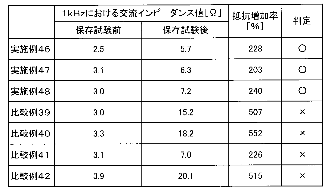
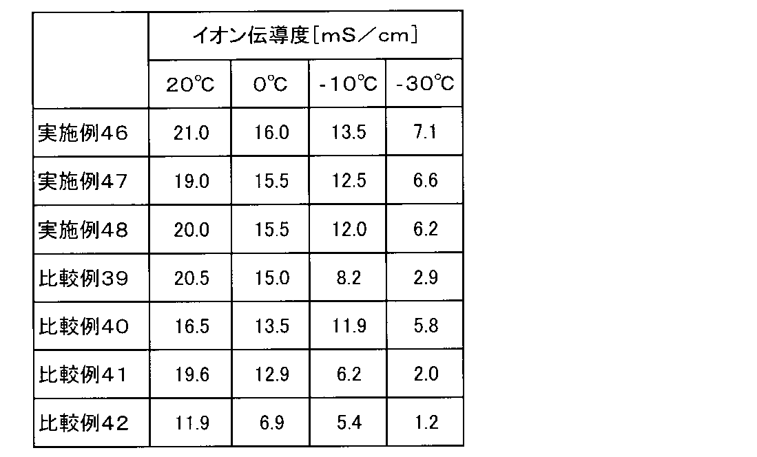
[電解液の調製]
各種溶媒及び添加剤を所定の体積比になるように混ぜることで電解液を調製した。実施例及び比較例で用いた各電解液の組成は表32に示した。なお、表32において「AcN」はアセトニトリル、「DEC」はジエチルカーボネート、「EMC」はエチルメチルカーボネート、「EC」はエチレンカーボネート、「VC」はビニレンカーボネート、「LiPF6」はヘキサフルオロリン酸リチウム、「LiN(SO2F)2」はリチウムビス(フルオロスルホニル)イミド、「LiN(SO2CF3)2」はリチウムビス(トリフルオロメタンスルホニル)イミド、「LiPO2F2」はジフルオロリン酸リチウム、「SAH」は無水コハク酸をそれぞれ示す。
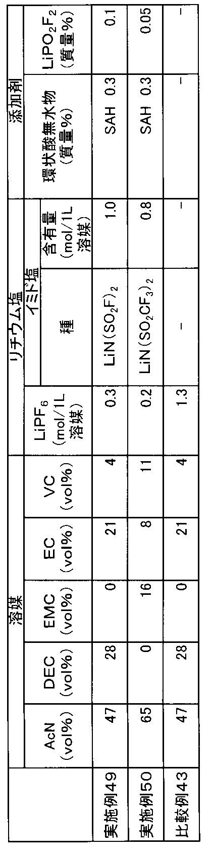
得られたデータは、インピーダンスの実数成分(Z´)と虚数成分(Z´´)からなるナイキスト線図で表した。そして、Z´´=0におけるZ´値(R)を読み取って、以下の式によりLiイオン伝導度を求めた。
Liイオン伝導度(mS/cm)=d/(R・S)
ここで、dは、電極間距離(0.35cm)、Sは、電極面積(4.522cm2)である。
上記の式より得られた各温度におけるLiイオン伝導度を用い、アレニウスの式:σ=Aexp(-Ea/kT)(σ:イオン伝導度、A:頻度因子、k:ボルツマン定数、T:絶対温度)より、-20~0℃と0~20℃のアレニウスプロットの傾きを求めた。

(1-1) 正極の作製
正極活物質として数平均粒子径11μmのリチウムとニッケル、マンガン及びコバルトとの複合酸化物(Ni/Mn/Co=1/1/1(元素比);密度4.70g/cm3)と、導電助剤として数平均粒子径6.5μmのグラファイト炭素粉末(密度2.26g/cm3)及び数平均粒子径48nmのアセチレンブラック粉末(密度1.95g/cm3)と、バインダーとしてポリフッ化ビニリデン(PVdF;密度1.75g/cm3)とを、100:4.2:1.8:4.6の質量比で混合し、正極合剤を得た。得られた正極合剤に溶剤としてN-メチル-2-ピロリドンを固形分68質量%となるように投入して更に混合して、正極合剤含有スラリーを調製した。正極集電体となる厚さ20μm、幅200mmのアルミニウム箔の片面に、この正極合剤含有スラリーを目付量が12.0mg/cm2になるように調節しながらドクターブレード法で塗布し、溶剤を乾燥除去した。その後、ロールプレスで実電極密度が2.80g/cm3になるよう圧延して、正極活物質層と正極集電体からなる正極を得た。
負極活物質として数平均粒子径12.7μmのグラファイト炭素粉末(密度2.23g/cm3)及び数平均粒子径6.5μmのグラファイト炭素粉末(密度2.27g/cm3)と、バインダーとしてカルボキシメチルセルロース(密度1.60g/cm3)溶液(固形分濃度1.83質量%)と、ジエン系ゴム(ガラス転移温度:-5℃、乾燥時の数平均粒子径:120nm、密度1.00g/cm3、分散媒:水、固形分濃度40質量%)とを、87.2:9.7:1.4:1.7の固形分質量比で混合し、負極合剤を得た。得られた負極合剤に溶剤として水を固形分45質量%となるように投入して更に混合して、負極合剤含有スラリーを調製した。負極集電体となる厚さ10μm、幅200mmの銅箔の片面に、この負極合剤含有スラリーを目付量が5.3mg/cm2になるよう調節しながらドクターブレード法で塗布し、溶剤を乾燥除去した。その後、ロールプレスで実電極密度が1.30g/cm3になるよう圧延して、負極活物質層と負極集電体からなる負極を得た。
CR2032タイプの電池ケース(SUS304/Alクラッド)にポリプロピレン製ガスケットをセットし、その中央に上述のようにして得られた正極を直径16mmの円盤状に打ち抜いたものを、正極活物質層を上向きにしてセットした。その上からポリエチレン微多孔膜を直径19mmの円盤状に打ち抜いたものをセットして、電解液を100μL注入した後、上述のようにして得られた負極を直径16mmの円盤状に打ち抜いたものを、負極活物質層を下向きにしてセットした。さらにスペーサーとスプリングをセットした後に電池キャップをはめ込み、カシメ機でかしめた。あふれた電解液はウエスできれいにふきとった。25℃で24時間保持し、積層体に電解液を十分馴染ませてコイン型非水系二次電池を得た。
上述のようにして得られた評価用電池について、実施例および比較例に記載されているそれぞれの手順に従って初回充電処理後を行った。次に(2-1)、(2-2)の手順に従ってそれぞれの電池を評価した。なお、充放電はアスカ電子(株)製の充放電装置ACD-01(商品名)及び二葉科学社製の恒温槽PLM-63S(商品名)を用いて行った。
初回充放電処理(初回放電のエージング処理については各実施例や比較例の欄に記載)を行った電池について、電池の周囲温度を25℃に設定し、1Cに相当する3mAの定電流で充電して4.2Vに到達した後、4.2Vの定電圧で合計3時間充電を行った。次に、この非水系二次電池を85℃の恒温槽に4時間保存した。その後、電池の周囲温度を25℃に戻した。
上記(2-1)に記載の方法で85℃満充電保存試験を行った電池について、電池の周囲温度を25℃に設定し、1Cに相当する3mAの定電流で充電して4.2Vに到達した後、4.2Vの定電圧で合計3時間充電を行った。その後、1Cに相当する3mAの電流値で3.0Vまで放電した。次に、定電流放電時の電流値を5Cに相当する15mAに変更した以外は、上記と同様の充放電を行い、下記の容量維持率を算出した。
容量維持率=(5C放電時の容量/1C放電時の容量)×100[%]
不活性雰囲気下、アセトニトリル(AcN)とジエチルカーボネート(DEC)とエチレンカーボネート(EC)とビニレンカーボネート(VC)の体積比が45:35:16:4となるよう混合し混合溶媒を得た。さらに、この混合溶媒に無水コハク酸(SAH)を電解液として最終的に0.15質量%となるよう溶解させた。その後、混合溶媒1Lあたり0.3molのヘキサフルオロリン酸リチウム(LiPF6)と1.3molのリチウムビス(フルオロスルホニル)イミド(LiN(SO2F)2)を添加し、実施例100の電解液を得た。得られた電解液について、目視でリチウム塩が全て溶解していることを確認した。この電解液を用いて上記(1-3)に記載の方法で電池作製した後、初回充放電処理を行った。電池の周囲温度を25℃に設定し、0.1Cに相当する0.3mAの定電流で充電して2.8Vまで充電した後、2.8Vの定電圧で1時間半充電を行った。その後、周囲温度を55℃に設定し、6時間保存した後、再び電池の周囲温度を25℃に設定し、冷却のため3時間静置した。その後、0.1Cに相当する0.3mAの定電流で充電して4.2Vに到達した後、4.2Vの定電圧で合計1.5時間充電を行った。その後、0.3Cに相当する0.9mAの定電流で3.0Vまで放電した。このときの放電容量を充電容量で割ることによって、初回効率を算出した。その後、上記(2-1)、(2-2)に記載の手順でコイン型非水系二次電池の評価を行った。
不活性雰囲気下、アセトニトリル(AcN)とエチルメチルカーボネート(EMC)とエチレンカーボネート(EC)とビニレンカーボネート(VC)の体積比が45:35:16:4となるよう混合し混合溶媒を得た。さらに、この混合溶媒に無水コハク酸(SAH)を電解液として最終的に0.3質量%となるよう溶解させた。更に、この混合溶媒に1-メチル-1H-ベンゾトリアゾール(MBTA)を電解液として最終的に0.2質量%となるよう溶解させた。その後、混合溶媒1Lあたり1.3molのヘキサフルオロリン酸リチウム(LiPF6)を添加し、実施例101の電解液を得た。得られた電解液について、目視でリチウム塩が全て溶解していることを確認した。この電解液を用いて上記(1-3)に記載の方法で電池作製した後、初回充放電処理を行った。電池の周囲温度を25℃に設定し、0.1Cに相当する0.3mAの定電流で充電して2.8Vまで充電した後、2.8Vの定電圧で1時間半充電を行った。その後、周囲温度を45℃に設定し、72時間保存した後、再び電池の周囲温度を25℃に設定し、冷却のため3時間静置した。その後、0.1Cに相当する0.3mAの定電流で充電して4.2Vに到達した後、4.2Vの定電圧で合計1.5時間充電を行った。その後、0.3Cに相当する0.9mAの定電流で3.0Vまで放電した。このときの放電容量を充電容量で割ることによって、初回効率を算出した。その後、上記(2-1)(2-2)に記載の手順でコイン型非水系二次電池の評価を行った。
不活性雰囲気下、アセトニトリル(AcN)とエチルメチルカーボネート(EMC)とエチレンカーボネート(EC)とビニレンカーボネート(VC)の体積比が35:40:21:4となるよう混合し混合溶媒を得た。さらに、この混合溶媒に無水マレイン酸(MAH)を電解液として最終的に0.15質量%となるよう溶解させた。更に、この混合溶媒に1-メチル-1H-ベンゾトリアゾール(MBTA)を電解液として最終的に0.1質量%となるよう溶解させた。その後、混合溶媒1Lあたり1.2molのヘキサフルオロリン酸リチウム(LiPF6)を添加し、実施例102の電解液を得た。得られた電解液について、目視でリチウム塩が全て溶解していることを確認した。この電解液を用いて上記(1-3)に記載の方法で電池作製した後、初回充放電処理を行った。電池の周囲温度を25℃に設定し、0.1Cに相当する0.3mAの定電流で充電して3.0Vまで充電した後、3.0Vの定電圧で1時間半充電を行った。その後、周囲温度を55℃に設定し、6時間保存した後、再び電池の周囲温度を25℃に設定し、冷却のため3時間静置した。その後、0.1Cに相当する0.3mAの定電流で充電して4.2Vに到達した後、4.2Vの定電圧で合計1.5時間充電を行った。その後、0.3Cに相当する0.9mAの定電流で3.0Vまで放電した。このときの放電容量を充電容量で割ることによって、初回効率を算出した。その後、上記(2-1)(2-2)に記載の手順でコイン型非水系二次電池の評価を行った。
不活性雰囲気下、アセトニトリル(AcN)とジメチルカーボネート(DMC)とエチレンカーボネート(EC)とビニレンカーボネート(VC)の体積比が65:6:22:7となるよう混合し混合溶媒を得た。さらに、この混合溶媒に無水コハク酸(SAH)を電解液として最終的に0.2質量%となるよう溶解させた。さらに、この混合溶媒にメチルスクシノニトリルを電解液として最終的に0.2質量%となるよう溶解させた。その後、混合溶媒1Lあたり0.6molのヘキサフルオロリン酸リチウム(LiPF6)と0.6molのリチウムビス(トリフルオロメタンスルホニル)イミド(LiN(SO2CF3)2)を添加し、実施例103の電解液を得た。得られた電解液について、目視でリチウム塩が全て溶解していることを確認した。この電解液を用いて上記(1-3)に記載の方法で電池作製した後、初回充放電処理を行った。電池の周囲温度を25℃に設定し、0.1Cに相当する0.3mAの定電流で充電して3.0Vまで充電した後、3.0Vの定電圧で1時間半充電を行った。その後、周囲温度を60℃に設定し、6時間保存した後、再び電池の周囲温度を25℃に設定し、冷却のため3時間静置した。その後、0.1Cに相当する0.3mAの定電流で充電して4.2Vに到達した後、4.2Vの定電圧で合計1.5時間充電を行った。その後、0.3Cに相当する0.9mAの定電流で3.0Vまで放電した。このときの放電容量を充電容量で割ることによって、初回効率を算出した。その後、上記(2-1)(2-2)に記載の手順でコイン型非水系二次電池の評価を行った。
不活性雰囲気下、アセトニトリル(AcN)とジエチルカーボネート(DEC)とエチレンカーボネート(EC)とビニレンカーボネート(VC)の体積比が45:30:23:2となるよう混合し混合溶媒を得た。さらに、この混合溶媒に無水コハク酸(SAH)を電解液として最終的に0.2質量%となるよう溶解させた。更に、この混合溶媒に1-メチル-1H-ベンゾトリアゾール(MBTA)を電解液として最終的に0.3質量%となるよう溶解させた。その後、混合溶媒1Lあたり1.0molのヘキサフルオロリン酸リチウム(LiPF6)を添加し、実施例104の電解液を得た。得られた電解液について、目視でリチウム塩が全て溶解していることを確認した。この電解液を用いて上記(1-3)に記載の方法で電池作製した後、初回充放電処理を行った。電池の周囲温度を25℃に設定し、0.1Cに相当する0.3mAの定電流で充電して3.3Vまで充電した後、3.3Vの定電圧で1時間半充電を行った。その後、周囲温度を55℃に設定し、24時間保存した後、再び電池の周囲温度を25℃に設定し、冷却のため3時間静置した。その後、0.1Cに相当する0.3mAの定電流で充電して4.2Vに到達した後、4.2Vの定電圧で合計1.5時間充電を行った。その後、0.3Cに相当する0.9mAの定電流で3.0Vまで放電した。このときの放電容量を充電容量で割ることによって、初回効率を算出した。その後、上記(2-1)(2-2)に記載の手順でコイン型非水系二次電池の評価を行った。
不活性雰囲気下、アセトニトリル(AcN)とエチルメチルカーボネート(EMC)とエチレンカーボネート(EC)とビニレンカーボネート(VC)の体積比が50:30:18:2となるよう混合し混合溶媒を得た。さらに、この混合溶媒に無水コハク酸(SAH)を電解液として最終的に0.2質量%となるよう溶解させた。その後、混合溶媒1Lあたり0.3molのヘキサフルオロリン酸リチウム(LiPF6)と1.0molのリチウムビス(フルオロスルホニル)イミド(LiN(SO2F)2)を添加し、実施例105の電解液を得た。得られた電解液について、目視でリチウム塩が全て溶解していることを確認した。この電解液を用いて上記(1-3)に記載の方法で電池作製した後、初回充放電処理を行った。電池の周囲温度を25℃に設定し、0.1Cに相当する0.3mAの定電流で充電して3.2Vまで充電した後、3.2Vの定電圧で1時間半充電を行った。その後、周囲温度を50℃に設定し、48時間保存した後、再び電池の周囲温度を25℃に設定し、冷却のため3時間静置した。その後、0.1Cに相当する0.3mAの定電流で充電して4.2Vに到達した後、4.2Vの定電圧で合計1.5時間充電を行った。その後、0.3Cに相当する0.9mAの定電流で3.0Vまで放電した。このときの放電容量を充電容量で割ることによって、初回効率を算出した。その後、上記(2-1)(2-2)に記載の手順でコイン型非水系二次電池の評価を行った。
不活性雰囲気下、アセトニトリル(AcN)とジエチルカーボネート(DEC)とビニレンカーボネート(VC)の体積比が47:42:11となるよう混合した。この混合溶媒に無水マレイン酸(環状酸無水物)を電解液として最終的に0.14質量%となるよう溶解させた。さらにこの混合液1Lあたり1.3molのヘキサフルオロリン酸リチウム(LiPF6)と0.01molのリチウムビス(フルオロスルホニル)イミド(LiN(SO2F)2)を添加して、比較例100の電解液を得た。得られた電解液について、目視でリチウム塩が全て溶解していることを確認した。この電解液を用いて上記(1-3)に記載の方法で電池作製した後、初回充放電処理を行った。電池の周囲温度を25℃に設定し、0.1Cに相当する0.3mAの定電流で充電して4.2Vに到達した後、4.2Vの定電圧で合計1.5時間充電を行った。その後、0.3Cに相当する0.9mAの定電流で3.0Vまで放電した。このときの放電容量を充電容量で割ることによって、初回効率を算出した。その後、上記(2-1)(2-2)に記載の手順でコイン型非水系二次電池の評価を行った。比較例100では、初回充電のエージング処理を行っていない。
不活性雰囲気下、アセトニトリル(AcN)とジエチルカーボネート(DEC)とビニレンカーボネート(VC)の体積比が47:49:4となるよう混合した。さらにこの混合液1Lあたり1.3molのヘキサフルオロリン酸リチウム(LiPF6)と0.05molのリチウムビス(トリフルオロメタンスルホニル)イミド(LiN(SO2CF3)2)を添加するとともに、無水コハク酸(SAH)を0.05質量%溶解させ、比較例101の電解液を得た。得られた電解液について、目視でリチウム塩が全て溶解していることを確認した。この電解液を用いて上記(1-3)に記載の方法で電池作製した後、初回充放電処理を行った。電池の周囲温度を25℃に設定し、0.1Cに相当する0.3mAの定電流で充電して2.8Vまで充電した後、2.8Vの定電圧で1時間半充電を行った。その後、周囲温度を25℃のままとし、72時間保存した後、電池の周囲温度をそのまま25℃に設定し、3時間静置した。その後、0.1Cに相当する0.3mAの定電流で充電して4.2Vに到達した後、4.2Vの定電圧で合計1.5時間充電を行った。その後、0.3Cに相当する0.9mAの定電流で3.0Vまで放電した。このときの放電容量を充電容量で割ることによって、初回効率を算出した。その後、上記(2-1)(2-2)に記載の手順でコイン型非水系二次電池の評価を行った。
不活性雰囲気下、アセトニトリル(AcN)とジエチルカーボネート(DEC)とビニレンカーボネート(VC)の体積比が47:49:4となるよう混合し混合溶媒を得た。さらにこの混合溶媒に無水コハク酸(SAH)を電解液として最終的に0.05質量%となるよう溶解させた。更に、この混合溶媒に1-メチル-1H-ベンゾトリアゾール(MBTA)を電解液として最終的に2.5質量%となるよう溶解させた。その後、混合溶媒1Lあたり0.3molのヘキサフルオロリン酸リチウム(LiPF6)と1molのリチウムビス(トリフルオロメタンスルホニル)イミド(LiN(SO2CF3)2)を添加し、比較例102の電解液を得た。得られた電解液について、目視でリチウム塩が全て溶解していることを確認した。この電解液を用いて上記(1-3)に記載の方法で電池作製した後、初回充放電処理を行った。電池の周囲温度を25℃に設定し、0.1Cに相当する0.3mAの定電流で充電して4.2Vまで充電した後、4.2Vの定電圧で合計1.5時間充電を行った。その後、周囲温度を85℃とし、24時間保存した後、電池の周囲温度をそのまま25℃に設定し、冷却のため3時間静置した。その後、0.1Cに相当する0.3mAの定電流で充電して4.2Vに到達した後、4.2Vの定電圧で1時間半充電を行った。その後、0.3Cに相当する0.9mAの定電流で3.0Vまで放電した。このときの放電容量を充電容量で割ることによって、初回効率を算出した。その後、上記(2-1)(2-2)に記載の手順でコイン型非水系二次電池の評価を行った。


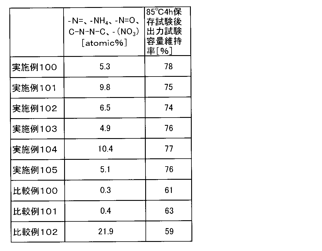
各種溶媒及び添加剤を所定の体積比になるように混ぜることで電解液を調製した。実施例及び比較例で用いた各電解液の組成は表37に示した。なお、表37において「AcN」はアセトニ
トリル、「DEC」はジエチルカーボネート、「EMC」はエチルメチルカーボネート、「DM
C」はジメチルカーボネート、「EC」はエチレンカーボネート、「VC」はビニレンカーボネート、「LiPF6」はヘキサフルオロリン酸リチウム、「LiN(SO2F)2」はリチウムビス(フルオロスルホニル)イミド、「LiN(SO2CF3)2」はリチウムビス(トリフルオロメタンスルホニル)イミド、「MBTA」は、1-メチル-1H-ベンゾトリアゾール、「SAH」は無水コハク酸、「MAH」は無水マレイン酸、「PAH」は無水フタル酸をそれぞれ示す。
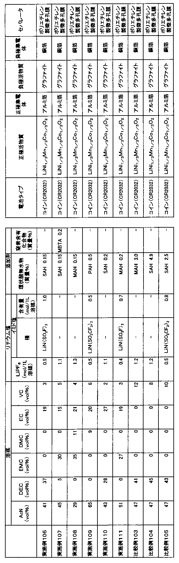
(1-1) 正極の作製
正極活物質として数平均粒子径11μmのリチウムとニッケル、マンガン及びコバルトとの複合酸化物(Ni/Mn/Co=1/1/1(元素比);密度4.70g/cm3)と、導電助剤として数平均粒子径6.5μmのグラファイト炭素粉末(密度2.26g/cm3)及び数平均粒子径48nmのアセチレンブラック粉末(密度1.95g/cm3)と、バインダーとしてポリフッ化ビニリデン(PVdF;密度1.75g/cm3)とを、100:4.2:1.8:4.6の質量比で混合し、正極合剤を得た。得られた正極合剤に溶剤としてN-メチル-2-ピロリドンを固形分68質量%となるように投入して更に混合して、正極合剤含有スラリーを調製した。正極集電体となる厚さ20μm、幅200mmのアルミニウム箔の片面に、この正極合剤含有スラリーを目付量が12.0mg/cm2になるように調節しながらドクターブレード法で塗布し、溶剤を乾燥除去した。その後、ロールプレスで実電極密度が2.80g/cm3になるよう圧延して、正極活物質層と正極集電体からなる正極を得た。
負極活物質として数平均粒子径12.7μmのグラファイト炭素粉末(密度2.23g/cm3)及び数平均粒子径6.5μmのグラファイト炭素粉末(密度2.27g/cm3)と、バインダーとしてカルボキシメチルセルロース(密度1.60g/cm3)溶液(固形分濃度1.83質量%)と、ジエン系ゴム(ガラス転移温度:-5℃、乾燥時の数平均粒子径:120nm、密度1.00g/cm3、分散媒:水、固形分濃度40質量%)とを、87.2:9.7:1.4:1.7の固形分質量比で混合し、負極合剤を得た。得られた負極合剤に溶剤として水を固形分45質量%となるように投入して更に混合して、負極合剤含有スラリーを調製した。負極集電体となる厚さ10μm、幅200mmの銅箔の片面に、この負極合剤含有スラリーを目付量が5.3mg/cm2になるよう調節しながらドクターブレード法で塗布し、溶剤を乾燥除去した。その後、ロールプレスで実電極密度が1.30g/cm3になるよう圧延して、負極活物質層と負極集電体からなる負極を得た。
CR2032タイプの電池ケース(SUS304/Alクラッド)にポリプロピレン製ガスケットをセットし、その中央に上述のようにして得られた正極を直径16mmの円盤状に打ち抜いたものを、正極活物質層を上向きにしてセットした。その上からポリエチレン微多孔膜を直径19mmの円盤状に打ち抜いたものをセットして、電解液を100μL注入した後、上述のようにして得られた負極を直径16mmの円盤状に打ち抜いたものを、負極活物質層を下向きにしてセットした。さらにスペーサーとスプリングをセットした後に電池キャップをはめ込み、カシメ機でかしめた。あふれた電解液はウエスできれいにふきとった。25℃で24時間保持し、積層体に電解液を十分馴染ませてコイン型非水系二次電池を得た。
上述のようにして得られた評価用電池について、実施例および比較例に記載されているそれぞれの手順に従って初回充電処理後を行った。次に(2-1)、(2-2)の手順に従ってそれぞれの電池を評価した。なお、充放電はアスカ電子(株)製の充放電装置ACD-01(商品名)及び二葉科学社製の恒温槽PLM-63S(商品名)を用いて行った。
初回充放電処理(初回放電のエージング処理については各実施例や比較例の欄に記載)を行った電池について、電池の周囲温度を25℃に設定し、1Cに相当する3mAの定電流で充電して4.2Vに到達した後、4.2Vの定電圧で合計3時間充電を行った。次に、この非水系二次電池を85℃の恒温槽に4時間保存した。その後、電池の周囲温度を25℃に戻した。
上記(2-1)に記載の方法で85℃満充電保存試験を行った電池について、電池の周囲温度を25℃に設定し、1Cに相当する3mAの定電流で充電して4.2Vに到達した後、4.2Vの定電圧で合計3時間充電を行った。その後、1Cに相当する3mAの電流値で3.0Vまで放電した。次に、定電流放電時の電流値を5Cに相当する15mAに変更した以外は、上記と同様の充放電を行い、下記の容量維持率を算出した。
容量維持率=(5C放電時の容量/1C放電時の容量)×100[%]
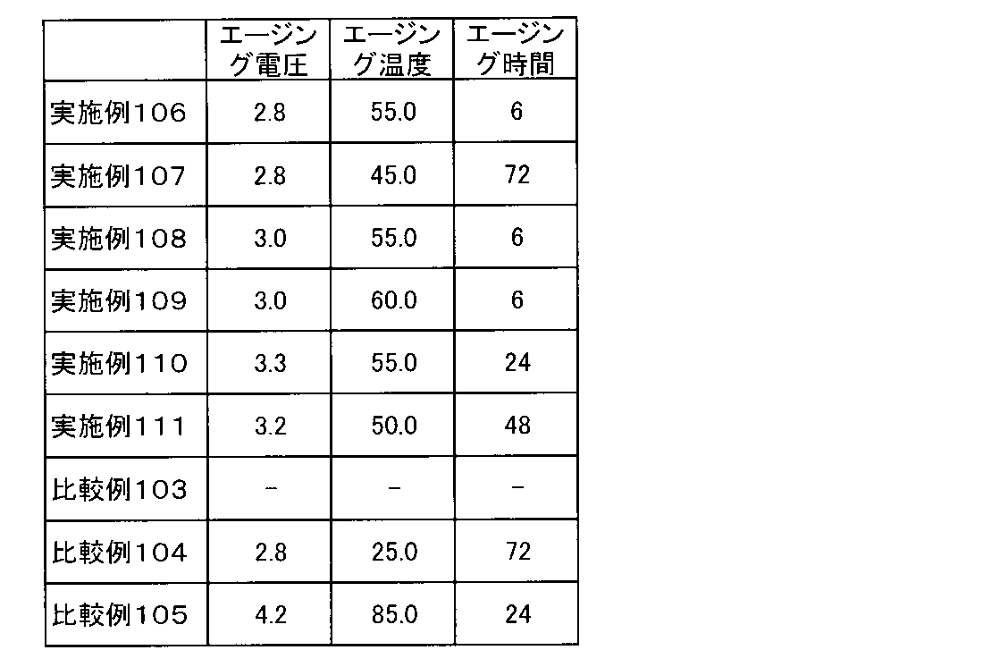
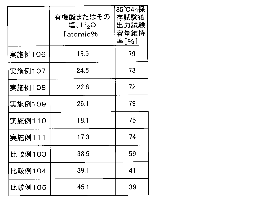
(1-1) 正極の作製
正極活物質として数平均粒子径11μmのリチウムとニッケル、マンガン及びコバルトとの複合酸化物(Ni/Mn/Co=1/1/1(元素比);密度4.70g/cm3)と、導電助剤として数平均粒子径6.5μmのグラファイト炭素粉末(密度2.26g/cm3)及び数平均粒子径48nmのアセチレンブラック粉末(密度1.95g/cm3)と、バインダーとしてポリフッ化ビニリデン(PVdF;密度1.75g/cm3)とを、100:4.2:1.8:4.6の質量比で混合し、正極合剤を得た。得られた正極合剤に溶剤としてN-メチル-2-ピロリドンを固形分68質量%となるように投入して更に混合して、正極合剤含有スラリーを調製した。この正極合剤含有スラリーを、正極集電体となる厚さ20μm、幅200mmのアルミニウム箔の両面に、片面あたりの目付量が11.5mg/cm2になるように調節しながらドクターブレード法で塗布し、溶剤を乾燥除去した。正極合剤含有スラリーをアルミニウム箔に塗布する際には、アルミニウム箔の一部が露出するように未塗布領域を形成した。その後、ロールプレスで実電極密度が2.80g/cm3になるよう圧延して、正極活物質層と正極集電体からなる正極を得た。
負極活物質として数平均粒子径12.7μmのグラファイト炭素粉末(密度2.23g/cm3)及び数平均粒子径6.5μmのグラファイト炭素粉末(密度2.27g/cm3)と、バインダーとしてカルボキシメチルセルロース(密度1.60g/cm3)溶液(固形分濃度1.83質量%)と、ジエン系ゴム(ガラス転移温度:-5℃、乾燥時の数平均粒子径:120nm、密度1.00g/cm3、分散媒:水、固形分濃度40質量%)とを、87.2:9.7:1.4:1.7の固形分質量比で混合し、負極合剤を得た。得られた負極合剤に溶剤として水を固形分45質量%となるように投入して更に混合して、負極合剤含有スラリーを調製した。この負極合剤含有スラリーを、負極集電体となる厚さ10μm、幅200mmの銅箔の両面に、片面あたりの目付量が6.9mg/cm2になるよう調節しながらドクターブレード法で塗布し、溶剤を乾燥除去した。負極合剤含有スラリーを銅箔に塗布する際には、銅箔の一部が露出するように未塗布領域を形成した。その後、ロールプレスで実電極密度が1.30g/cm3になるよう圧延して、負極活物質層と負極集電体からなる負極を得た。
リード付き正極とリード付き負極とを、各極の合剤塗布面が対向するようにポリエチレン製樹脂フィルムを介して重ね合わせて積層電極体とした。
上述のようにして得られた積層ラミネート電池について、(2-1)の手順に従って初回充放電処理を行った。続いて(2-2)及び(2-3)の手順に従ってそれぞれの電池を評価した。また、(2-4)の手順に従って電解液を評価した。
充電装置は菊水電子工業製バッテリテスタPFX2011を使用した。積層ラミネート電池の周囲温度を25℃に設定し、0.2Cの電流値で4.2Vまで定電流充電を行った後、4.2Vで1時間の定電圧充電を行った。その後、0.2Cに相当する定電流で2.7Vになるまで放電した。その後、露点-60℃以下に制御されたグローブボックス内にて、電池の封止部を開口しガス抜きを行った。ガス抜き後、同じ環境下において真空シールを行った。
上記(2-1)に記載の方法で初回充放電処理を行った電池について、電池の周囲温度を25℃に設定し、1Cの定電流で充電して4.2Vに到達した後、4.2Vの定電圧で合計3時間充電を行った。次に、この非水系二次電池を85℃の恒温槽に4時間保存した。その後、電池の周囲温度を25℃に戻した。
電解液を東陽テクニカ製の密閉セル(セルサイズ:24mmφ×0.35mmt)に入れて封入し、ホルダー(SH1-Z)にはめ込んで結線した。更に、恒温槽に入れて交流インピーダンス測定を行った。電極には金を使用した。電解液の採取から密閉セルへの充填、封入まではArグローブBOX内で行った。
Liイオン伝導度(mS/cm)=d/(R・S)
ここで、dは、電極間距離(0.35cm)、Sは、電極面積(4.522cm2)である。
不活性雰囲気下、アセトニトリル(AcN)とエチルメチルカーボネート(EMC)とエチレンカーボネート(EC)とビニレンカーボネート(VC)の体積比が45:36:16:3となるよう混合し混合溶媒を得た。さらに、この混合溶媒に無水コハク酸(SAH)を電解液として最終的に0.18質量%となるよう溶解させた。更に、この混合溶媒に1-メチル-1H-ベンゾトリアゾール(MBTA)を電解液として最終的に0.1質量%となるよう溶解させた。このとき、混合液の温度は30℃であった。その後、混合溶媒1Lあたり0.5molのヘキサフルオロリン酸リチウム(LiPF6)と1.0molのリチウムビス(フルオロスルホニル)イミド(LiN(SO2F)2)を順番に添加し、実施例112の電解液を得た。このとき、電解液の温度は40℃であり、50℃以下の熱履歴のみを受けて生成された。得られた電解液について、目視でリチウム塩が全て溶解していることを確認した。この電解液について上記(1-3)に記載の方法で電池作製した後、上記(2-1)~(2-3)に記載の手順で評価を行い、最終的に、各温度のイオン伝導度を算出した。
不活性雰囲気下、アセトニトリル(AcN)とエチルメチルカーボネート(EMC)とエチレンカーボネート(EC)とビニレンカーボネート(VC)の体積比が55:25:16:4となるよう混合し混合溶媒を得た。さらに、この混合溶媒に無水コハク酸(SAH)を電解液として最終的に0.12質量%となるよう溶解させた。更に、この混合溶媒に1-メチル-1H-ベンゾトリアゾール(MBTA)を電解液として最終的に0.25質量%となるよう溶解させた。このとき、混合液の温度は30℃であった。その後、混合溶媒1Lあたり1.1molのヘキサフルオロリン酸リチウム(LiPF6)を添加し、実施例113の電解液を得た。このとき、電解液の温度は43℃であり、50℃以下の熱履歴のみを受けて生成された。得られた電解液について、目視でリチウム塩が全て溶解していることを確認した。この電解液について上記(1-3)に記載の方法で電池作製した後、上記(2-1)~(2-3)に記載の手順で評価を行い、最終的に、各温度のイオン伝導度を算出した。
不活性雰囲気下、アセトニトリル(AcN)とエチルメチルカーボネート(EMC)とエチレンカーボネート(EC)とビニレンカーボネート(VC)の体積比が31:45:21:3となるよう混合し混合溶媒を得た。さらに、この混合溶媒に無水マレイン酸(MAH)を電解液として最終的に0.1質量%となるよう溶解させた。さらに、この混合溶媒にアジポニトリルを電解液として最終的に0.1質量%となるよう溶解させた。このとき、混合液の温度は31℃であった。その後、混合溶媒1Lあたり1.3molのヘキサフルオロリン酸リチウム(LiPF6)を添加し、実施例114の電解液を得た。このとき、電解液の温度は42℃であり、50℃以下の熱履歴のみを受けて生成された。得られた電解液について、目視でリチウム塩が全て溶解していることを確認した。この電解液について上記(1-3)に記載の方法で電池作製した後、上記(2-1)~(2-3)に記載の手順で評価を行い、最終的に、各温度のイオン伝導度を算出した。
不活性雰囲気下、アセトニトリル(AcN)とジメチルカーボネート(DMC)とエチレンカーボネート(EC)とビニレンカーボネート(VC)の体積比が65:10:22:3となるよう混合し混合溶媒を得た。さらに、この混合溶媒に無水フタル酸(PAH)を電解液として最終的に0.45質量%となるよう溶解させた。さらに、この混合溶媒にアジポニトリルを電解液として最終的に0.4質量%となるよう溶解させた。このとき、混合液の温度は29℃であった。その後、混合溶媒1Lあたり0.6molのヘキサフルオロリン酸リチウム(LiPF6)と0.6molのリチウムビス(トリフルオロメタンスルホニル)イミド(LiN(SO2CF3)2)を順番に添加し、実施例115の電解液を得た。このとき、電解液の温度は41℃であり、50℃以下の熱履歴のみを受けて生成された。得られた電解液について、目視でリチウム塩が全て溶解していることを確認した。この電解液について上記(1-3)に記載の方法で電池作製した後、上記(2-1)~(2-3)に記載の手順で評価を行い、最終的に、各温度のイオン伝導度を算出した。
不活性雰囲気下、アセトニトリル(AcN)とエチルメチルカーボネート(EMC)とエチレンカーボネート(EC)とビニレンカーボネート(VC)の体積比が45:35:17:3となるよう混合し混合溶媒を得た。このとき、混合溶媒の温度は30℃であった。次に、この混合溶媒1Lあたり1.3molのヘキサフルオロリン酸リチウム(LiPF6)を容器に入れ、その上から混合溶媒を流し込むとともに、無水コハク酸(SAH)を0.02質量%、1-メチル-1H-ベンゾトリアゾール(MBTA)を0.02質量%溶解させ、比較例106の電解液を得た。このとき、電解液の温度は63℃であり、50℃以上の熱履歴を受けて生成された。得られた電解液について、目視でリチウム塩が全て溶解していることを確認した。この電解液について上記(1-3)に記載の方法で電池作製した後、上記(2-1)~(2-3)に記載の手順で評価を行い、最終的に、各温度のイオン伝導度を算出した。
不活性雰囲気下、アセトニトリル(AcN)とジエチルカーボネート(DEC)とビニレンカーボネート(VC)の体積比が41:48:11となるよう混合し混合溶媒を得た。更に、この混合溶媒にアジポニトリルを電解液として最終的に2質量%となるよう溶解させた。このとき、混合溶媒の温度は30℃であった。次に、この混合溶媒1Lあたり2.0molのヘキサフルオロリン酸リチウム(LiPF6)を容器に入れ、その上から混合溶媒を流し込み、比較例107の電解液を得た。このとき、電解液の温度は68℃であり、50℃以上の熱履歴を受けて生成された。得られた電解液について、目視でリチウム塩が全て溶解していることを確認した。なお、比較例107では、環状酸無水物を添加していない。この電解液について上記(1-3)に記載の方法で電池作製した後、上記(2-1)~(2-3)に記載の手順で評価を行い、最終的に、各温度のイオン伝導度を算出した。


各種溶媒及び添加剤を所定の体積比になるように混ぜることで電解液を調製した。実施例及び比較例で用いた各電解液の組成は表42に示した。なお、表42において「AcN」はアセトニトリル、「DEC」はジエチルカーボネート、「EMC」はエチルメチルカーボネート、「DMC」はジメチルカーボネート、「EC」はエチレンカーボネート、「VC」はビニレンカーボネート、「LiPF6」はヘキサフルオロリン酸リチウム、「LiN(SO2F)2」はリチウムビス(フルオロスルホニル)イミド、「LiN(SO2CF3)2」はリチウムビス(トリフルオロメタンスルホニル)イミド、「MBTA」は、1-メチル-1H-ベンゾトリアゾール、「SAH」は無水コハク酸、「MAH」は無水マレイン酸、「PAH」は無水フタル酸をそれぞれ示す。

(1-1) 正極の作製
正極活物質として数平均粒子径11μmのリチウムとニッケル、マンガン及びコバルトとの複合酸化物(Ni/Mn/Co=1/1/1(元素比);密度4.70g/cm3)と、導電助剤として数平均粒子径6.5μmのグラファイト炭素粉末(密度2.26g/cm3)及び数平均粒子径48nmのアセチレンブラック粉末(密度1.95g/cm3)と、バインダーとしてポリフッ化ビニリデン(PVdF;密度1.75g/cm3)とを、100:4.2:1.8:4.6の質量比で混合し、正極合剤を得た。得られた正極合剤に溶剤としてN-メチル-2-ピロリドンを固形分68質量%となるように投入して更に混合して、正極合剤含有スラリーを調製した。この正極合剤含有スラリーを、正極集電体となる厚さ20μm、幅200mmのアルミニウム箔の両面に、片面あたりの目付量が11.5mg/cm2になるように調節しながらドクターブレード法で塗布し、溶剤を乾燥除去した。正極合剤含有スラリーをアルミニウム箔に塗布する際には、アルミニウム箔の一部が露出するように未塗布領域を形成した。その後、ロールプレスで実電極密度が2.80g/cm3になるよう圧延して、正極活物質層と正極集電体からなる正極を得た。
負極活物質として数平均粒子径12.7μmのグラファイト炭素粉末(密度2.23g/cm3)及び数平均粒子径6.5μmのグラファイト炭素粉末(密度2.27g/cm3)と、バインダーとしてカルボキシメチルセルロース(密度1.60g/cm3)溶液(固形分濃度1.83質量%)と、ジエン系ゴム(ガラス転移温度:-5℃、乾燥時の数平均粒子径:120nm、密度1.00g/cm3、分散媒:水、固形分濃度40質量%)とを、87.2:9.7:1.4:1.7の固形分質量比で混合し、負極合剤を得た。得られた負極合剤に溶剤として水を固形分45質量%となるように投入して更に混合して、負極合剤含有スラリーを調製した。この負極合剤含有スラリーを、負極集電体となる厚さ10μm、幅200mmの銅箔の両面に、片面あたりの目付量が6.9mg/cm2になるよう調節しながらドクターブレード法で塗布し、溶剤を乾燥除去した。負極合剤含有スラリーを銅箔に塗布する際には、銅箔の一部が露出するように未塗布領域を形成した。その後、ロールプレスで実電極密度が1.30g/cm3になるよう圧延して、負極活物質層と負極集電体からなる負極を得た。
リード付き正極とリード付き負極とを、各極の合剤塗布面が対向するようにポリエチレン製樹脂フィルムを介して重ね合わせて積層電極体とした。
上述のようにして得られた積層ラミネート電池について、(2-1)の手順に従って初回充放電処理を行った。続いて(2-2)及び(2-3)の手順に従ってそれぞれの電池を評価した。また、(2-4)の手順に従って電解液を評価した。
充電装置は菊水電子工業製バッテリテスタPFX2011を使用した。積層ラミネート電池の周囲温度を25℃に設定し、0.2Cの電流値で4.2Vまで定電流充電を行った後、4.2Vで1時間の定電圧充電を行った。その後、0.2Cに相当する定電流で2.7Vになるまで放電した。その後、露点-60℃以下に制御されたグローブボックス内にて、電池の封止部を開口しガス抜きを行った。ガス抜き後、同じ環境下において真空シールを行った。
上記(2-1)に記載の方法で初回充放電処理を行った電池について、電池の周囲温度を25℃に設定し、1Cの定電流で充電して4.2Vに到達した後、4.2Vの定電圧で合計3時間充電を行った。次に、この非水系二次電池を85℃の恒温槽に4時間保存した。その後、電池の周囲温度を25℃に戻した。
電解液を東陽テクニカ製の密閉セル(セルサイズ:24mmφ×0.35mmt)に入れて封入し、ホルダー(SH1-Z)にはめ込んで結線した。更に、恒温槽に入れて交流インピーダンス測定を行った。電極には金を使用した。電解液の採取から密閉セルへの充填、封入まではArグローブBOX内で行った。
Liイオン伝導度(mS/cm)=d/(R・S)
ここで、dは、電極間距離(0.35cm)、Sは、電極面積(4.522cm2)である。
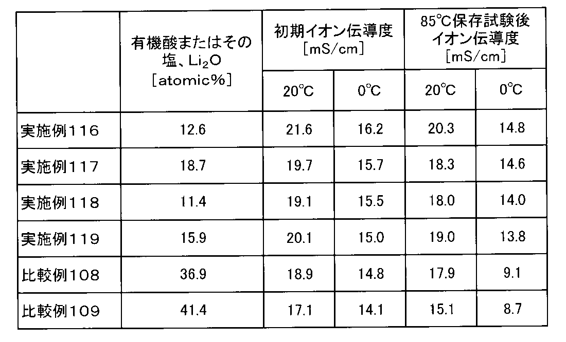
各種溶媒及び添加剤を所定の体積比になるように混ぜることで電解液を調製した。実施例及び比較例で用いた各電解液の組成は表44に示した。なお、表44において「AcN」はアセトニトリル、「DEC」はジエチルカーボネート、「EMC」はエチルメチルカーボネート、「DMC」はジメチルカーボネート、「EC」はエチレンカーボネート、「VC」はビニレンカーボネート、「LiPF6」はヘキサフルオロリン酸リチウム、「LiN(SO2F)2」はリチウムビス(フルオロスルホニル)イミド、「LiN(SO2CF3)2」はリチウムビス(トリフルオロメタンスルホニル)イミド、「MBTA」は、1-メチル-1H-ベンゾトリアゾール、「SAH」は無水コハク酸をそれぞれ示す。
正極活物質としてリチウム、ニッケル、マンガン、及びコバルトの複合酸化物(LiNi0.8Mn0.1Co0.1O2)と、導電助剤としてアセチレンブラック粉末と、バインダーとしてポリフッ化ビニリデン(PVDF)とを、100:4.3:4.3の質量比で混合し、正極合剤を得た。得られた正極合剤に溶剤としてN-メチル-2-ピロリドンを投入して更に混合して、正極合剤含有スラリーを調製した。正極集電体となる厚さ15μmのアルミニウム箔片面に、この正極合剤含有スラリーを、目付量が約180g/m2になるように調節しながら塗布した。正極合剤含有スラリーをアルミニウム箔に塗布する際には、アルミニウム箔の一部が露出するように未塗布領域を形成した。その後、ロールプレスで正極活物質層の密度が2.80g/cm3になるように圧延することにより、正極活物質層と正極集電体とからなる正極を得た。
負極活物質である黒鉛と、導電助剤としてアセチレンブラック粉末と、バインダーとしてポリフッ化ビニリデン(PVDF)とを、100:2.2:5.4の質量比で混合し、負極合剤を得た。得られた負極合剤に溶剤としてN-メチル-2-ピロリドンを投入した後に十分に混合して、負極合剤含有スラリーを調製した。このスラリーを、厚みが10μmの銅箔の片面に、目付量が約110.0g/m2になるように調節しながら一定厚みで塗布した。負極合剤含有スラリーを銅箔に塗布する際には、銅箔の一部が露出するように未塗布領域を形成した。その後、ロールプレスで負極活物質層の密度が1.5g/cm3になるように圧延することにより、負極活物質層と負極集電体とからなる負極を得た。
リード付き正極とリード付き負極とを、各極の合剤塗布面が対向するようにポリエチレン製微多孔膜セパレータ(厚み21μm)を介して重ね合わせて積層電極体とした。この積層電極体を、90mm×80mmのアルミニウムラミネートシート外装体内に収容し、水分を除去するために80℃で5時間真空乾燥を行った。続いて、上記した各電解液を外装体内に注入した後、外装体を封止することにより、単層ラミネート型(パウチ型)非水系二次電池(以下、単に「単層ラミネート電池」ともいう。)を作製した。この単層ラミネート電池は、設計容量値が7.5mAh、定格電圧値が4.2Vのものである。

上述のようにして得られた評価用電池について、下記の手順に従ってそれぞれの電池を評価した。
電池の周囲温度を25℃に設定し、1Cに相当する7.5mAの定電流で充電して4.2Vに到達した後、7.5mAの定電流で2.7Vまで放電した。充電と放電とを各々1回ずつ行うこの工程を1サイクルとし、100サイクルの充放電を行った。1サイクル目の放電容量を100%としたときの100サイクル目の放電容量を容量維持率とした。
電池の周囲温度を25℃に設定し、1Cに相当する7.5mAの定電流で充電して4.3Vに到達した後、7.5mAの定電流で2.7Vまで放電した。充電と放電とを各々1回ずつ行うこの工程を1サイクルとし、100サイクルの充放電を行った。1サイクル目の放電容量を100%としたときの100サイクル目の放電容量を容量維持率とした。その実験結果が、表45に示されている。
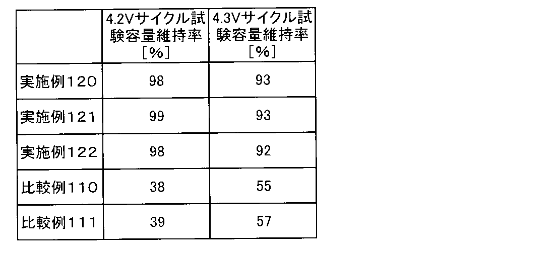
各種溶媒及び添加剤を所定の体積比になるように混ぜることで電解液を調製した。実施例及び比較例で用いた各電解液の組成は表46に示した。なお、表46において「AcN」はアセトニトリル、「DEC」はジエチルカーボネート、「EMC」はエチルメチルカーボネート、「DMC」はジメチルカーボネート、「EC」はエチレンカーボネート、「VC」はビニレンカーボネート、「LiPF6」はヘキサフルオロリン酸リチウム、「LiN(SO2F)2」はリチウムビス(フルオロスルホニル)イミド、「LiN(SO2CF3)2」はリチウムビス(トリフルオロメタンスルホニル)イミド、「SAH」は無水コハク酸、「MAH」は無水マレイン酸をそれぞれ示す。
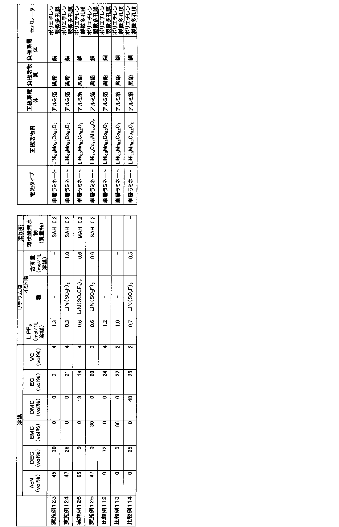
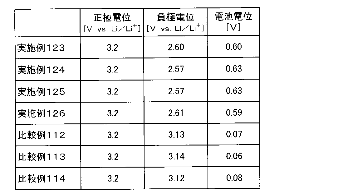
各種溶媒及び添加剤を所定の体積比になるように混ぜることで電解液を調製した。実施例及び比較例で用いた各電解液の組成は表48に示した。なお、表48において「AcN」はアセトニトリル、「DEC」はジエチルカーボネート、「EMC」はエチルメチルカーボネート、「DMC」はジメチルカーボネート、「EC」はエチレンカーボネート、「VC」はビニレンカーボネート、「LiPF6」はヘキサフルオロリン酸リチウム、「LiBOB」はリチウムビスオキサレートボレート、「LiN(SO2F)2」はリチウムビス(フルオロスルホニル)イミド、「LiN(SO2CF3)2」はリチウムビス(トリフルオロメタンスルホニル)イミド、「SAH」は無水コハク酸、「MAH」は無水マレイン酸、「PAH」は無水フタル酸をそれぞれ示す。

〔正極の作製〕
正極活物質としてリチウム、ニッケル、マンガン、及びコバルトの複合酸化物(LiNi0.5Mn0.3Co0.2O2)と、導電助剤としてアセチレンブラック粉末と、バインダーとしてポリフッ化ビニリデン(PVDF)とを、100:3.5:3の質量比で混合し、正極合剤を得た。得られた正極合剤に溶剤としてN-メチル-2-ピロリドンを投入して更に混合して、正極合剤含有スラリーを調製した。正極集電体となる厚さ15μmのアルミニウム箔片面に、この正極合剤含有スラリーを、目付量が約95.0g/m2になるように調節しながら塗布した。正極合剤含有スラリーをアルミニウム箔に塗布する際には、アルミニウム箔の一部が露出するように未塗布領域を形成した。その後、ロールプレスで正極活物質層の密度が2.74g/cm3になるように圧延することにより、正極活物質層と正極集電体とからなる正極を得た。
負極活物質である黒鉛と、バインダーであるカルボキシメチルセルロースと、同じくバインダーであるスチレンブタジエンラテックスとを、100:1.1:1.5の質量比で混合し、負極合剤を得た。得られた負極合剤に適量の水を添加した後に十分に混合して、負極合剤含有スラリーを調製した。このスラリーを、厚みが10μmの銅箔の片面に、目付量が約61.0g/m2になるように調節しながら一定厚みで塗布した。負極合剤含有スラリーを銅箔に塗布する際には、銅箔の一部が露出するように未塗布領域を形成した。その後、ロールプレスで負極活物質層の密度が1.20g/cm3になるように圧延することにより、負極活物質層と負極集電体とからなる負極を得た。
リード付き正極とリード付き負極とを、各極の合剤塗布面が対向するようにポリエチレン製微多孔膜セパレータ(厚み21μm)を介して重ね合わせて積層電極体とした。この積層電極体を、90mm×80mmのアルミニウムラミネートシート外装体内に収容し、水分を除去するために80℃で5時間真空乾燥を行った。続いて、上記した各電解液を外装体内に注入した後、外装体を封止することにより、単層ラミネート型(パウチ型)非水系二次電池(以下、単に「単層ラミネート電池」ともいう。)を作製した。この単層ラミネート電池は、設計容量値が23mAh、定格電圧値が4.2Vのものである。
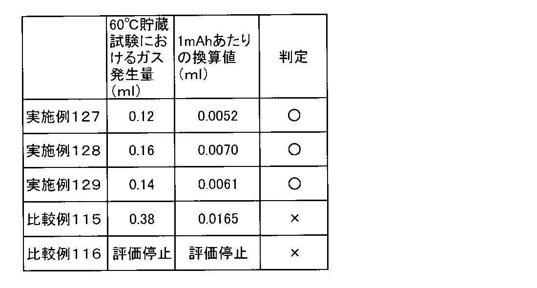
各種溶媒及び添加剤を所定の体積比になるように混ぜることで電解液を調製した。実施例及び比較例で用いた各電解液の組成は表50に示した。なお、表50において「AcN」はアセトニトリル、「DEC」はジエチルカーボネート、「EMC」はエチルメチルカーボネート、「DMC」はジメチルカーボネート、「EC」はエチレンカーボネート、「VC」はビニレンカーボネート、「LiPF6」はヘキサフルオロリン酸リチウム、「LiN(SO2F)2」はリチウムビス(フルオロスルホニル)イミド、「LiN(SO2CF3)2」はリチウムビス(トリフルオロメタンスルホニル)イミド、「SAH」は無水コハク酸、「MAH」は無水マレイン酸、「PAH」は無水フタル酸をそれぞれ示す。
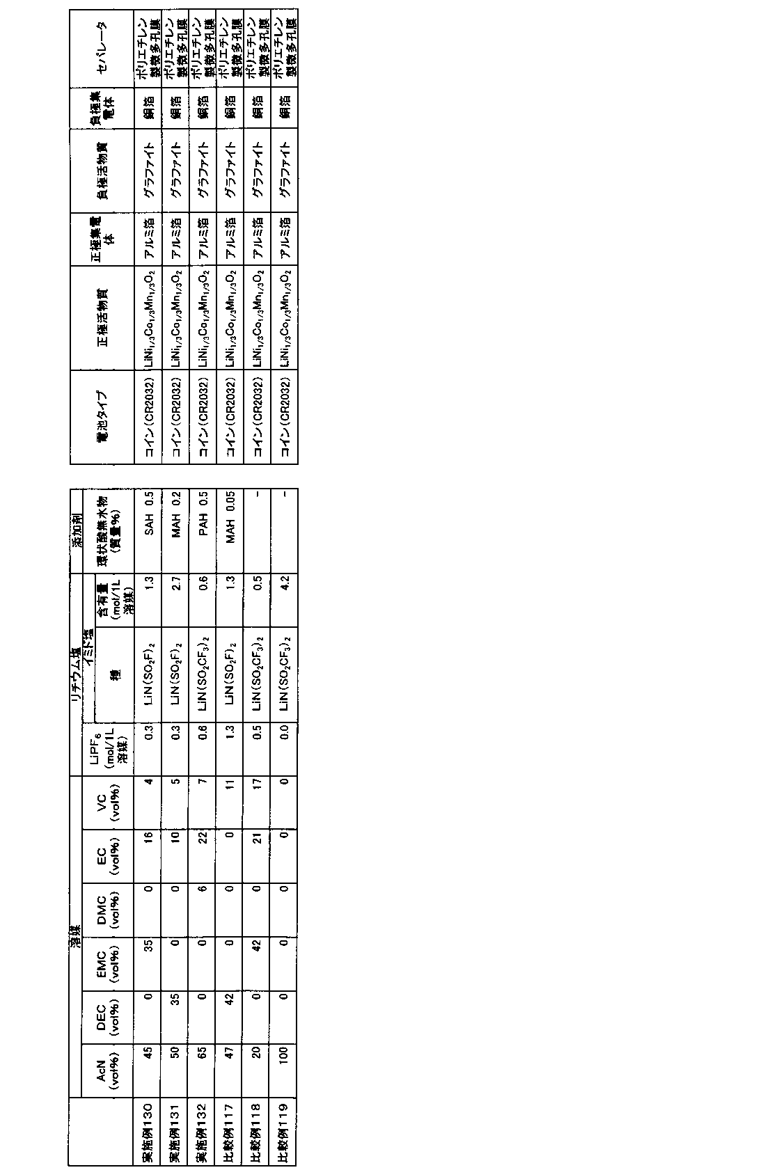
〔正極の作製〕
正極活物質としてリチウム、ニッケル、マンガン、及びコバルトの複合酸化物(LiNi0.5Mn0.3Co0.2O2)と、導電助剤としてアセチレンブラック粉末と、バインダーとしてポリフッ化ビニリデン(PVDF)とを、100:3.5:3の質量比で混合し、正極合剤を得た。得られた正極合剤に溶剤としてN-メチル-2-ピロリドンを投入して更に混合して、正極合剤含有スラリーを調製した。正極集電体となる厚さ15μmのアルミニウム箔片面に、この正極合剤含有スラリーを、目付量が約95.0g/m2になるように調節しながら塗布した。正極合剤含有スラリーをアルミニウム箔に塗布する際には、アルミニウム箔の一部が露出するように未塗布領域を形成した。その後、ロールプレスで正極活物質層の密度が2.74g/cm3になるように圧延することにより、正極活物質層と正極集電体とからなる正極を得た。
負極活物質である黒鉛と、バインダーであるカルボキシメチルセルロースと、同じくバインダーであるスチレンブタジエンラテックスとを、100:1.1:1.5の質量比で混合し、負極合剤を得た。得られた負極合剤に適量の水を添加した後に十分に混合して、負極合剤含有スラリーを調製した。このスラリーを、厚みが10μmの銅箔の片面に、目付量が約61.0g/m2になるように調節しながら一定厚みで塗布した。負極合剤含有スラリーを銅箔に塗布する際には、銅箔の一部が露出するように未塗布領域を形成した。その後、ロールプレスで負極活物質層の密度が1.20g/cm3になるように圧延することにより、負極活物質層と負極集電体とからなる負極を得た。
リード付き正極とリード付き負極とを、各極の合剤塗布面が対向するようにポリエチレン製微多孔膜セパレータ(厚み21μm)を介して重ね合わせて積層電極体とした。この積層電極体を、90mm×80mmのアルミニウムラミネートシート外装体内に収容し、水分を除去するために80℃で5時間真空乾燥を行った。続いて、上記した各電解液を外装体内に注入した後、外装体を封止することにより、単層ラミネート型(パウチ型)非水系二次電池(以下、単に「単層ラミネート電池」ともいう。)を作製した。この単層ラミネート電池は、設計容量値が23mAh、定格電圧値が4.2Vのものである。
上述のようにして得られた評価用電池について、まず、下記(1-1)の手順に従って初回充電処理を行った。次に(1-2)(1-3)の手順に従ってそれぞれの電池を評価した。なお、充放電はアスカ電子(株)製の充放電装置ACD-01(商品名)及び二葉科学社製の恒温槽PLM-63S(商品名)を用いて行った。
電池の周囲温度を25℃に設定し、0.1Cに相当する2.3mAの定電流で充電して4.2Vに到達した後、4.2Vの定電圧で合計1.5時間充電を行った。その後、0.3Cに相当する6.9mAの定電流で3.0Vまで放電した。このときの放電容量を充電容量で割ることによって、初回効率を算出した。
実験では、単層ラミネート電池について、25℃において、0.05Cの電流値で4.2Vになるまで定電流充電を行った後、4.2Vで1.5時間の定電圧充電を行った。そして、この充電後の単層ラミネート電池を60℃の恒温槽内で貯蔵した。720時間経過後、単層ラミネート電池を恒温槽から取り出して室温に戻した。
交流インピーダンス測定は、ソーラトロン社製周波数応答アナライザ1400(商品名)とソーラトロン社製ポテンショ-ガルバノスタット1470E(商品名)を用いた。1000kHz~0.01Hzに周波数を変えつつ交流信号を付与し、電圧・電流の応答信号からインピーダンスを測定し、1kHzにおける交流インピーダンス値を求め抵抗値とした。印可する交流電圧の振幅は±5mVとした。また、交流インピーダンスを測定する際の電池の周囲温度は25℃とした。また、これらの結果から下記の値を算出した。
抵抗増加率=(60℃満充電保存試験後の抵抗値/60℃満充電保存試験前の抵抗値)×100[%]

式(2)
1モジュールあたりのセル直列接続数X:X=2,4,8、16
式(3)
セルパックあたりのモジュール直列接続数Y:Y=16/X
また、このセルパック7は、以下の式(2)に基づいて、前記非水系二次電池(LIB)1のセル数を規定したセルパックを1個、或いは2個以上並列接続して構成されたモジュール6が、式(3)に基づいて直列接続されて構成している。なお、非水系二次電池1は各々2セル以上並列接続されていてもよい。
式(2)
1モジュールあたりのセル直列接続数X:X=2,4,8、16
式(3)
セルパックあたりのモジュール直列接続数Y:Y=16/X
Claims (46)
- アセトニトリルと、リチウム塩と、環状酸無水物と、を含有することを特徴とする非水系電解液。
- 前記非水系電解液が、PF6アニオンを含有することを特徴とする請求項1に記載の非水系電解液。
- 前記PF6アニオンは、LiPF6が解離したものであることを特徴とする請求項2に記載の非水系電解液。
- 前記環状酸無水物が、無水コハク酸、無水マレイン酸及び無水フタル酸のうち少なくとも1種を含むことを特徴とする請求項1から請求項3のいずれかに記載の非水系電解液。
- 前記環状酸無水物の含有量が、非水系電解液に対し、0.01質量%以上1質量%以下であることを特徴とする請求項1から請求項4のいずれかに記載の非水系電解液。
- 更に、鎖状カーボネートを含有することを特徴とする請求項1から請求項5のいずれかに記載の非水系電解液。
- 前記鎖状カーボネートが、ジエチルカーボネート、エチルメチルカーボネート及びジメチルカーボネートからなる群から選択される少なくとも1種であることを特徴とする請求項6に記載の非水系電解液。
- 前記アセトニトリルに対する前記鎖状カーボネートの混合モル比が、0.15以上2以下であることを特徴とする請求項6又は請求項7に記載の非水系電解液。
- 前記アセトニトリルに対する前記鎖状カーボネートの混合モル比が、0.25以上2以下であることを特徴とする請求項6又は請求項7に記載の非水系電解液。
- 前記アセトニトリルに対する前記鎖状カーボネートの混合モル比が、0.4以上2以下であることを特徴とする請求項6又は請求項7に記載の非水系電解液。
- 前記非水系電解液が、水を含有することを特徴とする請求項1から請求項10のいずれかに記載の非水系電解液。
- 前記水の含有量が、非水系電解液に対し、1ppm以上200ppm以下であることを特徴とする請求項11に記載の非水系電解液。
- 前記非水系電解液が、イミド塩を含有することを特徴とする請求項1から請求項12のいずれかに記載の非水系電解液。
- 前記イミド塩が、LiN(SO2F)2及びLiN(SO2CF3)2からなる群のうち少なくとも1種であることを特徴とする請求項13に記載の非水系電解液。
- 更に、飽和第二級炭素を有さない環状カーボネートを含有することを特徴とする請求項1から請求項14のいずれかに記載の非水系電解液。
- 前記飽和第二級炭素を有さない環状カーボネートが、エチレンカーボネート及びビニレンカーボネートからなる群から選択される少なくとも1種であることを特徴とする請求項15に記載の非水系電解液。
- 前記飽和第二級炭素を有さない環状カーボネートが、ビニレンカーボネートであって、ビニレンカーボネートの量が非水系電解液中、0.5体積%以上4体積%以下であることを特徴とする請求項16に記載の非水系電解液。
- 更に、前記環状カーボネートの塩素付加体である有機塩素化合物を含有することを特徴とする請求項15から請求項17のいずれかに記載の非水系電解液。
- 前記非水系電解液の-30℃におけるイオン伝導度が、3mS/cm以上であることを特徴とする請求項13から請求項14のいずれかに記載の非水系電解液。
- 前記非水系電解液の-10℃におけるイオン伝導度が、10mS/cm以上であることを特徴とする請求項1から請求項18のいずれかに記載の非水系電解液。
- 前記非水系電解液の20℃におけるイオン伝導度が、15mS/cm以上であることを特徴とする請求項1から請求項18のいずれかに記載の非水系電解液。
- 更に、酢酸を含有することを特徴とする請求項1から請求項21のいずれかに記載の非水系電解液。
- 更に、プロピオニトリルを含有することを特徴とする請求項22に記載の非水系電解液。
- 更に、アセトアルデヒドを含有することを特徴とする請求項1から請求項23のいずれかに記載の非水系電解液。
- 更に、2,6-ジ-tert-ブチル-p-クレゾールを含有することを特徴とする請求項1から請求項24のいずれかに記載の非水系電解液。
- 更に、以下の式(1)を有する化合物を含有することを特徴とする請求項1から請求項25のいずれかに記載の非水系電解液。

- 前記化合物は、窒素含有環状化合物であることを特徴とする請求項26に記載の非水系電解液。
- 前記リチウム塩の主成分は、前記イミド塩であり、或いは、前記イミド塩と、前記イミド塩以外の前記リチウム塩とが主成分として同量含まれることを特徴とする請求項13又は請求項14に記載の非水系電解液。
- LiPF6≦イミド塩となるモル濃度で前記イミド塩を含有することを特徴とする請求項13、請求項14又は請求項28のいずれかに記載の非水系電解液。
- 前記イミド塩の含有量は、非水系溶媒1Lに対して、0.5mol以上3.0mol以下であることを特徴とする請求項13、請求項14、請求項28、又は請求項29のいずれかに記載の非水系電解液。
- 前記アセトニトリルに対するPF6アニオンの混合モル比が、0.01以上0.08未満であることを特徴とする請求項13、請求項14、又は請求項28から請求項30のいずれかに記載の非水系電解液。
- 前記リチウム塩が、PO2F2アニオンを含有することを特徴とする請求項1から請求項31のいずれかに記載の非水系電解液。
- 前記PO2F2アニオンの含有量が、非水系電解液に対し、0.001質量%以上1質量%以下であることを特徴とする請求項32に記載の非水系電解液。
- 前記非水系電解液のイオン伝導における活性化エネルギーが-20~0℃において15kJ/mol以下であることを特徴とする請求項13、請求項14、請求項28、請求項30、又は請求項31のいずれかに記載の非水系電解液。
- 集電体の片面又は両面に、正極活物質層を有する正極と、集電体の片面又は両面に、負極活物質層を有する負極と、非水系電解液と、を具備する非水系二次電池において、
前記非水系二次電池に、-N=、-NH4、-N=O、-NH-NH-、及び(NO3)-からなる群から選ばれる少なくとも一種の官能基を有する化合物が含まれ、
前記非水系二次電池は、85℃での4時間保存試験後にて、5C放電容量を1C放電容量で除して算出してなる容量維持率は、70%以上であることを特徴とする非水系二次電池。 - 集電体の片面又は両面に、正極活物質層を有する正極と、集電体の片面又は両面に、負極活物質層を有する負極と、非水系電解液と、を具備する非水系二次電池において、
前記非水系二次電池に有機酸およびその塩、無水酸、並びにLi2Oからなる群から選ばれる少なくとも一種の化合物が含まれ、
前記有機酸は、酢酸、シュウ酸またはギ酸のうち少なくとも1種を含み、
前記非水系二次電池は、85℃での4時間保存試験後にて、5C放電容量を1C放電容量で除して算出してなる容量維持率は、70%以上であることを特徴とする非水系二次電池。 - 集電体の片面又は両面に、正極活物質層を有する正極と、集電体の片面又は両面に、負極活物質層を有する負極と、非水系電解液と、を具備する非水系二次電池において、
前記非水系二次電池に、-N=、-NH4、-N=O、-NH-NH-、及び(NO3)-からなる群から選ばれる少なくとも一種の官能基を有する化合物が含まれ、
前記非水系二次電池は、85℃での4時間保存試験後における、0℃でのイオン伝導度が、10mS/cm以上であることを特徴とする非水系二次電池。 - 集電体の片面又は両面に、正極活物質層を有する正極と、集電体の片面又は両面に、負極活物質層を有する負極と、非水系電解液と、を具備する非水系二次電池において、
前記非水系二次電池に有機酸およびその塩、無水酸、並びにLi2Oからなる群から選ばれる少なくとも一種の化合物が含まれ、
前記有機酸は、酢酸、シュウ酸またはギ酸のうち少なくとも1種を含み、
前記非水系二次電池は、85℃での4時間保存試験後における、0℃でのイオン伝導度が、10mS/cm以上であることを特徴とする非水系二次電池。 - 正極活物質がLizMO2(MはNiを含み、且つ、Mn、Co、Al、及びMgからなる群より選ばれる1種以上の金属元素を含み、さらに、Niの元素含有比は50%より多い。また、zは0.9超1.2未満の数を示す。)で表されるリチウム含有複合金属酸化物であることを特徴とする請求項35から請求項38のいずれかに記載の非水系二次電池。
- 前記非水系電解液の注液前後における負極電位差が0.3V以上であることを特徴とする請求項35から請求項39のいずれかに記載の非水系二次電池。
- 60℃での200時間貯蔵試験におけるガス発生量が1mAhあたり0.008ml以下であることを特徴とする請求項35から請求項40のいずれかに記載の非水系二次電池。
- 60℃での720時間満充電保存試験における抵抗増加率が400%以下であることを特徴とする請求項35から請求項41のいずれかに記載の非水系二次電池。
- 請求項35から請求項42のいずれかに記載の非水系二次電池を備えたセルパックであって、
前記正極活物質層にFeが含まれるリチウム含有化合物を含有し、
前記負極活物質層に黒鉛、またはTi、V、Sn、Cr、Mn、Fe、Co、Ni、Zn、Al、Si、及びBからなる群から選択される少なくとも1種以上の元素を含有し、
前記非水系電解液には、飽和第二級炭素を有さない環状カーボネートを含有し、前記飽和第二級炭素を有さない環状カーボネートが、エチレンカーボネート及びビニレンカーボネートからなる群から選択される少なくとも1種であり、
前記非水系二次電池が4セル直列接続されたモジュールを1モジュール、あるいは2モジュール以上並列接続して構成され、または、前記非水系二次電池が2セル以上並列接続されたモジュールを4モジュール直列接続して構成されており、
1セルあたりの作動電圧範囲が1.8V-3.7Vの範囲内であり、且つ平均作動電圧が2.5V-3.5Vであり、
前記モジュールにはBMSが搭載されている、ことを特徴とするセルパック。 - 請求項43に記載のセルパックと、リチウムイオン電池以外の二次電池から構成されるモジュールまたはセルパックと、を組み合わせてなることを特徴とするハイブリッドシステム。
- 請求項35から請求項42のいずれかに記載の非水系二次電池を備えたセルパックであって、
前記正極活物質層にFeが含まれるリチウム含有化合物を含有し、
前記負極活物質層に黒鉛、またはTi、V、Sn、Cr、Mn、Fe、Co、Ni、Zn、Al、Si、及びBからなる群から選択される少なくとも1種以上の元素を含有し、
前記非水系電解液には、飽和第二級炭素を有さない環状カーボネートを含有し、前記飽和第二級炭素を有さない環状カーボネートが、エチレンカーボネート及びビニレンカーボネートからなる群から選択される少なくとも1種であり、
式(2)及び式(3)に基づいて、前記非水系二次電池のセル数及びモジュール数を規定した前記セルパックを1個、或いは2個以上並列接続して構成され、または、前記非水系二次電池が2セル以上並列接続したモジュールが式(2)及び式(3)に基づいて接続されて前記セルパックを構成しており、
1セルあたりの作動電圧範囲が1.8V-3.7Vの範囲内であり、且つ平均作動電圧が2.5V-3.5Vであり、前記モジュールにはBMSが搭載されている、ことを特徴とするセルパック。
式(2)
1モジュールあたりのセル直列接続数X:X=2,4,8、16
式(3)
セルパックあたりのモジュール直列接続数Y:Y=16/X - 請求項45に記載のセルパックと、リチウムイオン電池以外の二次電池から構成されるモジュールまたはセルパックと、を組み合わせてなることを特徴とするハイブリッドシステム。
Priority Applications (7)
| Application Number | Priority Date | Filing Date | Title |
|---|---|---|---|
| EP18767214.2A EP3598558A4 (en) | 2017-03-17 | 2018-03-16 | WATER-FREE ELECTROLYTE, WATER-FREE SECONDARY BATTERY, CELL PACK AND HYBRID SYSTEM |
| KR1020217035021A KR102441300B1 (ko) | 2017-03-17 | 2018-03-16 | 비수계 전해액, 비수계 이차 전지, 셀 팩, 및 하이브리드 시스템 |
| JP2019506280A JP6974434B2 (ja) | 2017-03-17 | 2018-03-16 | 非水系電解液 |
| KR1020197024735A KR102321741B1 (ko) | 2017-03-17 | 2018-03-16 | 비수계 전해액, 비수계 이차 전지, 셀 팩, 및 하이브리드 시스템 |
| US16/489,554 US11515567B2 (en) | 2017-03-17 | 2018-03-16 | Non-aqueous electrolyte solution, non-aqueous secondary battery, cell pack, and hybrid power system |
| CN201880015059.4A CN110383564B (zh) | 2017-03-17 | 2018-03-16 | 非水系电解液、非水系二次电池、电池包和混合动力系统 |
| JP2021180264A JP7248764B2 (ja) | 2017-03-17 | 2021-11-04 | 非水系二次電池、セルパック、及び、ハイブリッドシステム |
Applications Claiming Priority (30)
| Application Number | Priority Date | Filing Date | Title |
|---|---|---|---|
| JP2017052258 | 2017-03-17 | ||
| JP2017052397 | 2017-03-17 | ||
| JP2017052259 | 2017-03-17 | ||
| JP2017-052086 | 2017-03-17 | ||
| JP2017052088 | 2017-03-17 | ||
| JP2017-052399 | 2017-03-17 | ||
| JP2017-052397 | 2017-03-17 | ||
| JP2017052085 | 2017-03-17 | ||
| JP2017052260 | 2017-03-17 | ||
| JP2017-052088 | 2017-03-17 | ||
| JP2017052257 | 2017-03-17 | ||
| JP2017052398 | 2017-03-17 | ||
| JP2017052086 | 2017-03-17 | ||
| JP2017-052396 | 2017-03-17 | ||
| JP2017-052260 | 2017-03-17 | ||
| JP2017-052085 | 2017-03-17 | ||
| JP2017-052255 | 2017-03-17 | ||
| JP2017052400 | 2017-03-17 | ||
| JP2017-052259 | 2017-03-17 | ||
| JP2017-052398 | 2017-03-17 | ||
| JP2017052256 | 2017-03-17 | ||
| JP2017-052258 | 2017-03-17 | ||
| JP2017-052254 | 2017-03-17 | ||
| JP2017052255 | 2017-03-17 | ||
| JP2017-052400 | 2017-03-17 | ||
| JP2017-052256 | 2017-03-17 | ||
| JP2017052396 | 2017-03-17 | ||
| JP2017-052257 | 2017-03-17 | ||
| JP2017052399 | 2017-03-17 | ||
| JP2017052254 | 2017-03-17 |
Publications (1)
| Publication Number | Publication Date |
|---|---|
| WO2018169028A1 true WO2018169028A1 (ja) | 2018-09-20 |
Family
ID=63523230
Family Applications (1)
| Application Number | Title | Priority Date | Filing Date |
|---|---|---|---|
| PCT/JP2018/010380 Ceased WO2018169028A1 (ja) | 2017-03-17 | 2018-03-16 | 非水系電解液、非水系二次電池、セルパック、及び、ハイブリッドシステム |
Country Status (7)
| Country | Link |
|---|---|
| US (1) | US11515567B2 (ja) |
| EP (1) | EP3598558A4 (ja) |
| JP (2) | JP6974434B2 (ja) |
| KR (2) | KR102441300B1 (ja) |
| CN (1) | CN110383564B (ja) |
| TW (2) | TWI664769B (ja) |
| WO (1) | WO2018169028A1 (ja) |
Cited By (15)
| Publication number | Priority date | Publication date | Assignee | Title |
|---|---|---|---|---|
| WO2019138724A1 (ja) * | 2018-01-15 | 2019-07-18 | パナソニックIpマネジメント株式会社 | 二次電池及び電解液 |
| JPWO2021066174A1 (ja) * | 2019-10-04 | 2021-04-08 | ||
| CN112640180A (zh) * | 2019-06-28 | 2021-04-09 | 旭化成株式会社 | 非水系电解液及非水系二次电池 |
| WO2021131742A1 (ja) * | 2019-12-26 | 2021-07-01 | 株式会社村田製作所 | 二次電池 |
| WO2021141784A1 (en) * | 2020-01-10 | 2021-07-15 | A123 Systems, LLC | Electrolyte compositions for lithium ion batteries |
| JPWO2021241761A1 (ja) * | 2020-05-28 | 2021-12-02 | ||
| JP2021197341A (ja) * | 2020-06-18 | 2021-12-27 | 旭化成株式会社 | 非水系二次電池 |
| JP2021197281A (ja) * | 2020-06-15 | 2021-12-27 | 旭化成株式会社 | 非水系電解液及び非水系二次電池 |
| KR20220009486A (ko) | 2019-09-13 | 2022-01-24 | 아사히 가세이 가부시키가이샤 | 비수계 전해액 및 비수계 이차 전지 |
| JP2022091475A (ja) * | 2020-12-09 | 2022-06-21 | 三菱ケミカル株式会社 | 電解液、電気化学素子電極用表面処理剤、電気化学素子電極の表面処理方法及び電気化学素子電極の製造方法 |
| JP2022530786A (ja) * | 2019-10-28 | 2022-07-01 | エルジー エナジー ソリューション リミテッド | リチウム-硫黄二次電池 |
| JP2023524581A (ja) * | 2020-05-07 | 2023-06-12 | ファーストキャップ・システムズ・コーポレイション | 広温度域電解質 |
| JPWO2024116931A1 (ja) * | 2022-11-29 | 2024-06-06 | ||
| JP2024169035A (ja) * | 2023-05-25 | 2024-12-05 | プライムプラネットエナジー&ソリューションズ株式会社 | リチウムイオン蓄電デバイスの検査方法及びデバイス群の製造方法 |
| US12512515B2 (en) | 2020-01-10 | 2025-12-30 | A123 Systems Llc | Electrolyte compositions for lithium ion batteries |
Families Citing this family (13)
| Publication number | Priority date | Publication date | Assignee | Title |
|---|---|---|---|---|
| JP7182198B2 (ja) * | 2018-01-31 | 2022-12-02 | パナソニックIpマネジメント株式会社 | 非水電解質二次電池、電解液及び非水電解質二次電池の製造方法 |
| EP3576210B1 (en) * | 2018-06-01 | 2023-05-31 | Panasonic Intellectual Property Management Co., Ltd. | Lithium secondary battery |
| JP6831409B2 (ja) * | 2019-02-27 | 2021-02-17 | トヨタ自動車株式会社 | リチウムイオン二次電池用電解液、リチウムイオン二次電池及びモジュール |
| WO2020250394A1 (ja) * | 2019-06-13 | 2020-12-17 | 昭和電工マテリアルズ株式会社 | 二次電池 |
| KR102630408B1 (ko) * | 2020-05-29 | 2024-01-30 | 아사히 가세이 가부시키가이샤 | 비수계 전해액, 셀 팩 및 셀 팩의 제조 방법 |
| US11631866B2 (en) * | 2020-06-08 | 2023-04-18 | Saft America | Lithium-ion primary pouch battery |
| CN114695943A (zh) * | 2020-12-29 | 2022-07-01 | 深圳新宙邦科技股份有限公司 | 一种锂离子电池 |
| KR20230150837A (ko) * | 2021-03-26 | 2023-10-31 | 아사히 가세이 가부시키가이샤 | 비수계 전해액 및 비수계 이차 전지 |
| CN115207441B (zh) * | 2021-04-13 | 2025-05-16 | 深圳新宙邦科技股份有限公司 | 一种磷酸铁锂电池 |
| CN115036575B (zh) * | 2022-08-10 | 2022-11-04 | 中创新航科技股份有限公司 | 一种电解液及含有该电解液的锂离子电池 |
| CN115498258A (zh) * | 2022-08-16 | 2022-12-20 | 深圳市德方创域新能源科技有限公司 | 电解液添加剂、锂离子电池电解液及锂离子电池 |
| CN115425289B (zh) * | 2022-09-27 | 2026-02-10 | 欣旺达动力科技股份有限公司 | 电解液、二次电池及用电设备 |
| WO2024259692A1 (zh) * | 2023-06-21 | 2024-12-26 | 宁德时代新能源科技股份有限公司 | 电池单体、电池、用电装置及储能装置 |
Citations (24)
| Publication number | Priority date | Publication date | Assignee | Title |
|---|---|---|---|---|
| JPH10208742A (ja) | 1997-01-29 | 1998-08-07 | Hitachi Ltd | 電 池 |
| JP2000012079A (ja) | 1998-06-24 | 2000-01-14 | Shin Kobe Electric Mach Co Ltd | 非水電解液二次電池 |
| JP2000123632A (ja) * | 1998-10-13 | 2000-04-28 | Daiso Co Ltd | 高分子固体電解質及びその用途 |
| JP2003157719A (ja) * | 2001-11-22 | 2003-05-30 | Hitachi Maxell Ltd | 常温溶融塩型固体電解質およびそれを用いた全固体電気化学素子 |
| JP2004259681A (ja) * | 2003-02-27 | 2004-09-16 | Sanyo Electric Co Ltd | 非水系リチウム二次電池 |
| JP2005050585A (ja) * | 2003-07-30 | 2005-02-24 | Sanyo Electric Co Ltd | リチウム二次電池 |
| JP2005072003A (ja) | 2003-08-20 | 2005-03-17 | Samsung Sdi Co Ltd | リチウム二次電池用電解液及びこれを含むリチウム二次電池 |
| JP2006245001A (ja) | 2005-02-28 | 2006-09-14 | Samsung Sdi Co Ltd | リチウム電池用電解質,および,リチウム電池 |
| JP2008305771A (ja) * | 2007-05-08 | 2008-12-18 | Sony Corp | 非水溶液電池 |
| JP2009218056A (ja) | 2008-03-10 | 2009-09-24 | Sony Corp | 二次電池 |
| JP2011154987A (ja) | 2009-12-29 | 2011-08-11 | Sony Corp | 非水電解質および非水電解質電池 |
| JP2012025764A (ja) | 2000-11-29 | 2012-02-09 | Mitsubishi Chemicals Corp | 高純度ビニレンカーボネート |
| WO2013054795A1 (ja) * | 2011-10-11 | 2013-04-18 | Kachi Naoyoshi | ハイブリッド蓄電池、これを用いた走行車輌及び電力貯蔵設備、走行車輌を用いたスマートグリッド走行車輌システム、並びに電力貯蔵設備を用いた電力供給ネットワークシステム |
| WO2013062056A1 (ja) | 2011-10-28 | 2013-05-02 | 旭化成株式会社 | 非水系二次電池 |
| JP2014007052A (ja) * | 2012-06-25 | 2014-01-16 | Nippon Shokubai Co Ltd | 非水電解液 |
| JP2014194930A (ja) | 2013-02-27 | 2014-10-09 | Mitsubishi Chemicals Corp | 非水系電解液及びそれを用いた非水系電解液電池 |
| JP2015090859A (ja) * | 2013-11-07 | 2015-05-11 | 旭化成株式会社 | 非水電解質二次電池 |
| JP2015133255A (ja) * | 2014-01-14 | 2015-07-23 | 旭化成株式会社 | 非水電解液及びリチウムイオン二次電池 |
| JP2015531738A (ja) * | 2013-01-10 | 2015-11-05 | エルジー・ケム・リミテッド | リチウムリン酸鉄ナノ粉末の製造方法 |
| WO2016021596A1 (ja) * | 2014-08-07 | 2016-02-11 | 日本電気株式会社 | リチウム二次電池およびその製造方法 |
| JP2016035901A (ja) | 2014-07-31 | 2016-03-17 | 株式会社東芝 | 非水電解質電池、非水電解質電池の製造方法及び電池パック |
| JP2016134283A (ja) * | 2015-01-19 | 2016-07-25 | 株式会社日本触媒 | 非水電解液及びこれを備えた蓄電デバイス |
| JP2016143536A (ja) | 2015-01-30 | 2016-08-08 | 三菱化学株式会社 | 非水系電解質、及びそれを用いた非水系電解質二次電池 |
| JP2016178125A (ja) * | 2015-03-18 | 2016-10-06 | 旭化成株式会社 | 非水系リチウム型蓄電素子 |
Family Cites Families (40)
| Publication number | Priority date | Publication date | Assignee | Title |
|---|---|---|---|---|
| JP3154719B2 (ja) | 1990-11-28 | 2001-04-09 | 東芝電池株式会社 | 非水電解液二次電池 |
| JP3311104B2 (ja) * | 1993-09-17 | 2002-08-05 | 株式会社東芝 | リチウム二次電池 |
| JP3756232B2 (ja) | 1996-01-17 | 2006-03-15 | 宇部興産株式会社 | 非水電解質二次電池 |
| JPH09204932A (ja) * | 1996-01-25 | 1997-08-05 | Fujitsu Ltd | リチウム二次電池用電解液及びリチウム二次電池 |
| JP3730491B2 (ja) | 1999-07-28 | 2006-01-05 | 三菱化学株式会社 | 制御電極表面を有する電池 |
| JP4599639B2 (ja) | 1999-11-22 | 2010-12-15 | 株式会社デンソー | 非水電解液二次電池 |
| US8076033B2 (en) | 2004-10-19 | 2011-12-13 | Mitsubishi Chemical Corporation | Method for producing difluorophosphate, nonaqueous electrolyte solution for secondary battery and nonaqueous electrolyte secondary battery |
| KR101338814B1 (ko) | 2005-06-20 | 2013-12-06 | 미쓰비시 가가꾸 가부시키가이샤 | 디플루오로인산염의 제조 방법, 2 차 전지용 비수계 전해액 및 비수계 전해액 2 차 전지 |
| TW200845464A (en) | 2005-11-15 | 2008-11-16 | Asahi Kasei Fibers Corp | Separator for electric accumulator and electricity accumulation device |
| EP2768067B1 (en) | 2006-12-06 | 2017-09-06 | Mitsubishi Chemical Corporation | Nonaqueous electrolytic solution and nonaqueous electrolyte secondary battery |
| CN105633345B (zh) | 2007-04-05 | 2020-01-17 | 三菱化学株式会社 | 二次电池用非水电解液以及使用该非水电解液的非水电解质二次电池 |
| US9806377B2 (en) | 2009-12-07 | 2017-10-31 | Sony Corporation | Secondary battery, electrolytic solution, battery pack, electronic device, and electrical vehicle |
| CN102195089B (zh) * | 2010-03-02 | 2016-09-14 | 索尼公司 | 非水电解质和非水电解质电池 |
| JP2011198508A (ja) | 2010-03-17 | 2011-10-06 | Sony Corp | リチウム二次電池、リチウム二次電池用電解液、電動工具、電気自動車および電力貯蔵システム |
| CN103190027B (zh) | 2010-10-29 | 2015-11-25 | 旭化成电子材料株式会社 | 非水系电解液和非水系二次电池 |
| US20130337344A1 (en) * | 2011-03-10 | 2013-12-19 | Kabushiki Kaisha Toyota Jidoshokki | Lithium ion secondary battery |
| JP5455975B2 (ja) * | 2011-05-30 | 2014-03-26 | 日立マクセル株式会社 | 正極活物質、並びにこれを用いたリチウムイオン二次電池用正極及びリチウムイオン二次電池 |
| CN102324562A (zh) * | 2011-08-29 | 2012-01-18 | 上海空间电源研究所 | 含氟取代丁二酸酐及丁二酸酐衍生物的非水电解液及包含它的碱金属二次电池 |
| KR101946011B1 (ko) * | 2011-09-22 | 2019-02-11 | 삼성전자주식회사 | 리튬 이차 전지용 전해질 및 이를 채용한 리튬 전지 |
| KR101472169B1 (ko) | 2011-10-28 | 2014-12-16 | 주식회사 엘지화학 | 리튬 이차전지용 전해액 및 이를 구비한 리튬 이차전지 |
| JP2013197061A (ja) | 2012-03-22 | 2013-09-30 | Nippon Shokubai Co Ltd | 電解液及び電極材料 |
| JP5977573B2 (ja) | 2012-04-27 | 2016-08-24 | 旭化成株式会社 | 非水系二次電池 |
| TWI586676B (zh) * | 2012-12-26 | 2017-06-11 | 國立台灣科技大學 | 製備應用於電化學電池之熱穩定性及電化學安定性的新型腈基-苯並咪唑鹽 |
| CN104253283A (zh) | 2013-06-28 | 2014-12-31 | 苏州宝时得电动工具有限公司 | 电池 |
| WO2015046175A1 (ja) | 2013-09-24 | 2015-04-02 | 旭硝子株式会社 | 二次電池用非水電解液及びリチウムイオン二次電池 |
| DE112014004442T5 (de) * | 2013-09-25 | 2016-06-23 | The University Of Tokyo | Nichtwässrige Elektrolytsekundärbatterie |
| JP2015065050A (ja) | 2013-09-25 | 2015-04-09 | 旭化成株式会社 | 非水系電解液及び非水系二次電池 |
| JP6520151B2 (ja) * | 2014-01-29 | 2019-05-29 | 三菱ケミカル株式会社 | 非水系電解液及び非水系電解液二次電池 |
| CN105006593B (zh) * | 2014-04-21 | 2017-12-12 | 宁德时代新能源科技股份有限公司 | 锂离子二次电池及其电解液 |
| CN106233524B (zh) | 2014-04-23 | 2020-06-19 | 株式会社村田制作所 | 二次电池用电解液、二次电池、电池组、电动车辆、蓄电系统、电动工具及电子设备 |
| JP6028957B2 (ja) | 2014-06-13 | 2016-11-24 | エルジー・ケム・リミテッド | 非水電解液及びこれを含むリチウム二次電池 |
| JP6570843B2 (ja) * | 2014-07-31 | 2019-09-04 | 株式会社東芝 | 非水電解質電池及び電池パック |
| JP6484995B2 (ja) | 2014-10-24 | 2019-03-20 | Tdk株式会社 | リチウムイオン二次電池 |
| WO2016095116A1 (en) * | 2014-12-17 | 2016-06-23 | Basf Corporation | Electrolyte compositions for rechargeable lithium ion batteries |
| WO2016159117A1 (ja) | 2015-03-31 | 2016-10-06 | 旭化成株式会社 | 非水系電解液及び非水系二次電池 |
| WO2016159108A1 (ja) * | 2015-03-31 | 2016-10-06 | 旭化成株式会社 | 非水系電解液及び非水系二次電池 |
| KR102587533B1 (ko) * | 2015-09-15 | 2023-10-12 | 삼성전자주식회사 | 이차 전지용 전해질 및 이를 포함하는 이차 전지 |
| EP3367490B1 (en) | 2015-09-16 | 2019-07-31 | Kabushiki Kaisha Toshiba | Secondary battery, battery pack, and vehicle |
| KR101976174B1 (ko) * | 2016-02-24 | 2019-05-09 | 주식회사 엘지화학 | 리튬 이차전지용 전극 조립체, 이를 포함하는 리튬 이차전지 및 전지모듈 |
| KR101809189B1 (ko) * | 2016-05-23 | 2017-12-14 | 한국제이씨씨(주) | 금속박, 금속박 제조방법 및 이를 이용한 전극 제조방법 |
-
2018
- 2018-03-16 EP EP18767214.2A patent/EP3598558A4/en active Pending
- 2018-03-16 TW TW107109168A patent/TWI664769B/zh active
- 2018-03-16 JP JP2019506280A patent/JP6974434B2/ja active Active
- 2018-03-16 KR KR1020217035021A patent/KR102441300B1/ko active Active
- 2018-03-16 WO PCT/JP2018/010380 patent/WO2018169028A1/ja not_active Ceased
- 2018-03-16 US US16/489,554 patent/US11515567B2/en active Active
- 2018-03-16 CN CN201880015059.4A patent/CN110383564B/zh active Active
- 2018-03-16 TW TW108108280A patent/TWI670880B/zh active
- 2018-03-16 KR KR1020197024735A patent/KR102321741B1/ko active Active
-
2021
- 2021-11-04 JP JP2021180264A patent/JP7248764B2/ja active Active
Patent Citations (25)
| Publication number | Priority date | Publication date | Assignee | Title |
|---|---|---|---|---|
| JPH10208742A (ja) | 1997-01-29 | 1998-08-07 | Hitachi Ltd | 電 池 |
| JP2000012079A (ja) | 1998-06-24 | 2000-01-14 | Shin Kobe Electric Mach Co Ltd | 非水電解液二次電池 |
| JP2000123632A (ja) * | 1998-10-13 | 2000-04-28 | Daiso Co Ltd | 高分子固体電解質及びその用途 |
| JP2012025764A (ja) | 2000-11-29 | 2012-02-09 | Mitsubishi Chemicals Corp | 高純度ビニレンカーボネート |
| JP2003157719A (ja) * | 2001-11-22 | 2003-05-30 | Hitachi Maxell Ltd | 常温溶融塩型固体電解質およびそれを用いた全固体電気化学素子 |
| JP2004259681A (ja) * | 2003-02-27 | 2004-09-16 | Sanyo Electric Co Ltd | 非水系リチウム二次電池 |
| JP2005050585A (ja) * | 2003-07-30 | 2005-02-24 | Sanyo Electric Co Ltd | リチウム二次電池 |
| JP2005072003A (ja) | 2003-08-20 | 2005-03-17 | Samsung Sdi Co Ltd | リチウム二次電池用電解液及びこれを含むリチウム二次電池 |
| JP2006245001A (ja) | 2005-02-28 | 2006-09-14 | Samsung Sdi Co Ltd | リチウム電池用電解質,および,リチウム電池 |
| JP2008305771A (ja) * | 2007-05-08 | 2008-12-18 | Sony Corp | 非水溶液電池 |
| JP2009218056A (ja) | 2008-03-10 | 2009-09-24 | Sony Corp | 二次電池 |
| JP2011154987A (ja) | 2009-12-29 | 2011-08-11 | Sony Corp | 非水電解質および非水電解質電池 |
| WO2013054795A1 (ja) * | 2011-10-11 | 2013-04-18 | Kachi Naoyoshi | ハイブリッド蓄電池、これを用いた走行車輌及び電力貯蔵設備、走行車輌を用いたスマートグリッド走行車輌システム、並びに電力貯蔵設備を用いた電力供給ネットワークシステム |
| WO2013062056A1 (ja) | 2011-10-28 | 2013-05-02 | 旭化成株式会社 | 非水系二次電池 |
| JP2017054822A (ja) * | 2011-10-28 | 2017-03-16 | 旭化成株式会社 | 非水系二次電池 |
| JP2014007052A (ja) * | 2012-06-25 | 2014-01-16 | Nippon Shokubai Co Ltd | 非水電解液 |
| JP2015531738A (ja) * | 2013-01-10 | 2015-11-05 | エルジー・ケム・リミテッド | リチウムリン酸鉄ナノ粉末の製造方法 |
| JP2014194930A (ja) | 2013-02-27 | 2014-10-09 | Mitsubishi Chemicals Corp | 非水系電解液及びそれを用いた非水系電解液電池 |
| JP2015090859A (ja) * | 2013-11-07 | 2015-05-11 | 旭化成株式会社 | 非水電解質二次電池 |
| JP2015133255A (ja) * | 2014-01-14 | 2015-07-23 | 旭化成株式会社 | 非水電解液及びリチウムイオン二次電池 |
| JP2016035901A (ja) | 2014-07-31 | 2016-03-17 | 株式会社東芝 | 非水電解質電池、非水電解質電池の製造方法及び電池パック |
| WO2016021596A1 (ja) * | 2014-08-07 | 2016-02-11 | 日本電気株式会社 | リチウム二次電池およびその製造方法 |
| JP2016134283A (ja) * | 2015-01-19 | 2016-07-25 | 株式会社日本触媒 | 非水電解液及びこれを備えた蓄電デバイス |
| JP2016143536A (ja) | 2015-01-30 | 2016-08-08 | 三菱化学株式会社 | 非水系電解質、及びそれを用いた非水系電解質二次電池 |
| JP2016178125A (ja) * | 2015-03-18 | 2016-10-06 | 旭化成株式会社 | 非水系リチウム型蓄電素子 |
Cited By (34)
| Publication number | Priority date | Publication date | Assignee | Title |
|---|---|---|---|---|
| JPWO2019138724A1 (ja) * | 2018-01-15 | 2021-01-07 | パナソニックIpマネジメント株式会社 | 二次電池及び電解液 |
| WO2019138724A1 (ja) * | 2018-01-15 | 2019-07-18 | パナソニックIpマネジメント株式会社 | 二次電池及び電解液 |
| US11646446B2 (en) | 2018-01-15 | 2023-05-09 | Panasonic Intellectual Property Management Co., Ltd. | Rechargeable battery and electrolyte solution |
| JP7174922B2 (ja) | 2018-01-15 | 2022-11-18 | パナソニックIpマネジメント株式会社 | 二次電池及び電解液 |
| JPWO2020262670A1 (ja) * | 2019-06-28 | 2021-09-13 | 旭化成株式会社 | 非水系電解液、及び非水系二次電池 |
| CN112640180A (zh) * | 2019-06-28 | 2021-04-09 | 旭化成株式会社 | 非水系电解液及非水系二次电池 |
| US11843092B2 (en) | 2019-09-13 | 2023-12-12 | Asahi Kasei Kabushiki Kaisha | Nonaqueous electrolyte solution and nonaqueous electrolyte secondary battery |
| KR20220009486A (ko) | 2019-09-13 | 2022-01-24 | 아사히 가세이 가부시키가이샤 | 비수계 전해액 및 비수계 이차 전지 |
| KR20220150997A (ko) | 2019-09-13 | 2022-11-11 | 아사히 가세이 가부시키가이샤 | 비수계 전해액 및 비수계 이차 전지 |
| JP7301995B2 (ja) | 2019-10-04 | 2023-07-03 | 旭化成株式会社 | 非水系リチウム蓄電素子 |
| WO2021066174A1 (ja) * | 2019-10-04 | 2021-04-08 | 旭化成株式会社 | 非水系リチウム蓄電素子 |
| JPWO2021066174A1 (ja) * | 2019-10-04 | 2021-04-08 | ||
| US12199268B2 (en) | 2019-10-04 | 2025-01-14 | Asahi Kasei Kabushiki Kaisha | Non-aqueous lithium power storage element |
| US12573655B2 (en) | 2019-10-28 | 2026-03-10 | Lg Energy Solution, Ltd. | Lithium-sulfur secondary battery |
| JP7254210B2 (ja) | 2019-10-28 | 2023-04-07 | エルジー エナジー ソリューション リミテッド | リチウム-硫黄二次電池 |
| JP2022530786A (ja) * | 2019-10-28 | 2022-07-01 | エルジー エナジー ソリューション リミテッド | リチウム-硫黄二次電池 |
| WO2021131742A1 (ja) * | 2019-12-26 | 2021-07-01 | 株式会社村田製作所 | 二次電池 |
| JP2023509767A (ja) * | 2020-01-10 | 2023-03-09 | エー123 システムズ エルエルシー | リチウムイオン電池の電解質成分 |
| WO2021141784A1 (en) * | 2020-01-10 | 2021-07-15 | A123 Systems, LLC | Electrolyte compositions for lithium ion batteries |
| US12512515B2 (en) | 2020-01-10 | 2025-12-30 | A123 Systems Llc | Electrolyte compositions for lithium ion batteries |
| JP2023524581A (ja) * | 2020-05-07 | 2023-06-12 | ファーストキャップ・システムズ・コーポレイション | 広温度域電解質 |
| KR20220035220A (ko) | 2020-05-28 | 2022-03-21 | 아사히 가세이 가부시키가이샤 | 비수계 이차 전지 및 비수계 전해액 |
| JP7359868B2 (ja) | 2020-05-28 | 2023-10-11 | 旭化成株式会社 | 非水系二次電池及び非水系電解液 |
| JPWO2021241761A1 (ja) * | 2020-05-28 | 2021-12-02 | ||
| US12199280B2 (en) | 2020-05-28 | 2025-01-14 | Asahi Kasei Kabushiki Kaisha | Non-aqueous secondary battery and non-aqueous electrolyte |
| JP7366845B2 (ja) | 2020-06-15 | 2023-10-23 | 旭化成株式会社 | 非水系電解液及び非水系二次電池 |
| JP2021197281A (ja) * | 2020-06-15 | 2021-12-27 | 旭化成株式会社 | 非水系電解液及び非水系二次電池 |
| JP2021197341A (ja) * | 2020-06-18 | 2021-12-27 | 旭化成株式会社 | 非水系二次電池 |
| JP7590126B2 (ja) | 2020-06-18 | 2024-11-26 | 旭化成株式会社 | 非水系二次電池 |
| JP2022091475A (ja) * | 2020-12-09 | 2022-06-21 | 三菱ケミカル株式会社 | 電解液、電気化学素子電極用表面処理剤、電気化学素子電極の表面処理方法及び電気化学素子電極の製造方法 |
| JP7599322B2 (ja) | 2020-12-09 | 2024-12-13 | Muアイオニックソリューションズ株式会社 | 電解液、電気化学素子電極用表面処理剤、電気化学素子電極の表面処理方法及び電気化学素子電極の製造方法 |
| JPWO2024116931A1 (ja) * | 2022-11-29 | 2024-06-06 | ||
| JP7727682B2 (ja) | 2023-05-25 | 2025-08-21 | プライムプラネットエナジー&ソリューションズ株式会社 | リチウムイオン蓄電デバイスの検査方法及びデバイス群の製造方法 |
| JP2024169035A (ja) * | 2023-05-25 | 2024-12-05 | プライムプラネットエナジー&ソリューションズ株式会社 | リチウムイオン蓄電デバイスの検査方法及びデバイス群の製造方法 |
Also Published As
| Publication number | Publication date |
|---|---|
| US11515567B2 (en) | 2022-11-29 |
| KR20190103453A (ko) | 2019-09-04 |
| JP6974434B2 (ja) | 2021-12-01 |
| CN110383564B (zh) | 2022-09-20 |
| US20190393556A1 (en) | 2019-12-26 |
| KR102441300B1 (ko) | 2022-09-08 |
| TW201840052A (zh) | 2018-11-01 |
| TWI670880B (zh) | 2019-09-01 |
| EP3598558A4 (en) | 2021-09-01 |
| JP7248764B2 (ja) | 2023-03-29 |
| JP2022017483A (ja) | 2022-01-25 |
| KR102321741B1 (ko) | 2021-11-04 |
| TW201924128A (zh) | 2019-06-16 |
| TWI664769B (zh) | 2019-07-01 |
| EP3598558A1 (en) | 2020-01-22 |
| JPWO2018169028A1 (ja) | 2020-01-16 |
| CN110383564A (zh) | 2019-10-25 |
| KR20210132242A (ko) | 2021-11-03 |
Similar Documents
| Publication | Publication Date | Title |
|---|---|---|
| JP7248764B2 (ja) | 非水系二次電池、セルパック、及び、ハイブリッドシステム | |
| US11532839B2 (en) | Non-aqueous secondary battery | |
| EP3279997B1 (en) | Nonaqueous electrolyte and nonaqueous secondary battery | |
| JP6767151B2 (ja) | 非水系電解液及び非水系二次電池 | |
| JP2018060693A (ja) | 非水系二次電池 | |
| JP2018060692A (ja) | 非水系二次電池 |
Legal Events
| Date | Code | Title | Description |
|---|---|---|---|
| 121 | Ep: the epo has been informed by wipo that ep was designated in this application |
Ref document number: 18767214 Country of ref document: EP Kind code of ref document: A1 |
|
| ENP | Entry into the national phase |
Ref document number: 20197024735 Country of ref document: KR Kind code of ref document: A |
|
| ENP | Entry into the national phase |
Ref document number: 2019506280 Country of ref document: JP Kind code of ref document: A |
|
| NENP | Non-entry into the national phase |
Ref country code: DE |
|
| WWE | Wipo information: entry into national phase |
Ref document number: 2018767214 Country of ref document: EP |
|
| ENP | Entry into the national phase |
Ref document number: 2018767214 Country of ref document: EP Effective date: 20191017 |