WO2018168911A1 - 電動モビリティおよびその分解方法 - Google Patents
電動モビリティおよびその分解方法 Download PDFInfo
- Publication number
- WO2018168911A1 WO2018168911A1 PCT/JP2018/009915 JP2018009915W WO2018168911A1 WO 2018168911 A1 WO2018168911 A1 WO 2018168911A1 JP 2018009915 W JP2018009915 W JP 2018009915W WO 2018168911 A1 WO2018168911 A1 WO 2018168911A1
- Authority
- WO
- WIPO (PCT)
- Prior art keywords
- rear wheel
- vehicle body
- wheel side
- tilt
- side vehicle
- Prior art date
Links
Images


Classifications
-
- B—PERFORMING OPERATIONS; TRANSPORTING
- B62—LAND VEHICLES FOR TRAVELLING OTHERWISE THAN ON RAILS
- B62K—CYCLES; CYCLE FRAMES; CYCLE STEERING DEVICES; RIDER-OPERATED TERMINAL CONTROLS SPECIALLY ADAPTED FOR CYCLES; CYCLE AXLE SUSPENSIONS; CYCLE SIDE-CARS, FORECARS, OR THE LIKE
- B62K5/00—Cycles with handlebars, equipped with three or more main road wheels
- B62K5/003—Cycles with four or more wheels, specially adapted for disabled riders, e.g. personal mobility type vehicles with four wheels
- B62K5/007—Cycles with four or more wheels, specially adapted for disabled riders, e.g. personal mobility type vehicles with four wheels power-driven
-
- A—HUMAN NECESSITIES
- A61—MEDICAL OR VETERINARY SCIENCE; HYGIENE
- A61G—TRANSPORT, PERSONAL CONVEYANCES, OR ACCOMMODATION SPECIALLY ADAPTED FOR PATIENTS OR DISABLED PERSONS; OPERATING TABLES OR CHAIRS; CHAIRS FOR DENTISTRY; FUNERAL DEVICES
- A61G5/00—Chairs or personal conveyances specially adapted for patients or disabled persons, e.g. wheelchairs
- A61G5/04—Chairs or personal conveyances specially adapted for patients or disabled persons, e.g. wheelchairs motor-driven
-
- A—HUMAN NECESSITIES
- A61—MEDICAL OR VETERINARY SCIENCE; HYGIENE
- A61G—TRANSPORT, PERSONAL CONVEYANCES, OR ACCOMMODATION SPECIALLY ADAPTED FOR PATIENTS OR DISABLED PERSONS; OPERATING TABLES OR CHAIRS; CHAIRS FOR DENTISTRY; FUNERAL DEVICES
- A61G5/00—Chairs or personal conveyances specially adapted for patients or disabled persons, e.g. wheelchairs
- A61G5/10—Parts, details or accessories
-
- B—PERFORMING OPERATIONS; TRANSPORTING
- B62—LAND VEHICLES FOR TRAVELLING OTHERWISE THAN ON RAILS
- B62K—CYCLES; CYCLE FRAMES; CYCLE STEERING DEVICES; RIDER-OPERATED TERMINAL CONTROLS SPECIALLY ADAPTED FOR CYCLES; CYCLE AXLE SUSPENSIONS; CYCLE SIDE-CARS, FORECARS, OR THE LIKE
- B62K15/00—Collapsible or foldable cycles
Definitions
- the present invention relates to an electric mobility and a disassembling method thereof.
- the present invention has been made in view of such circumstances, and after removing the rear wheel side vehicle body from the front wheel side vehicle body, the rear wheel side vehicle body is formed by a projecting member and a rear wheel protruding from the rear wheel.
- An object of the present invention is to provide an electric mobility that can be stably supported and that can improve the degree of freedom in designing the rear wheel side vehicle body and a method for disassembling the mobility.
- the electric mobility according to the first aspect of the present invention includes a front wheel side vehicle body, a rear wheel side vehicle body that is detachably connected to the front wheel side vehicle body, and one end side supported by the rear wheel side vehicle body so that it can tilt in the vertical direction.
- the other end of the rear wheel provided on the rear wheel side vehicle body protrudes forward or rearward of the vehicle and the tilting member so as not to tilt upward from the first tilting position.
- Means and an operation means capable of releasing the tilt restriction by the first restricting means.
- the projecting member when the tilt restriction by the first restricting means is released by the operating means, the projecting member is tilted to the second tilt position above the first tilt position, and the second restricting means is at that position. Therefore, the upward tilt is restricted.
- the other end portion of the protruding member in a state where the tilting restriction is performed by the first restricting means, the other end portion of the protruding member is positioned near the ground behind the vehicle rather than the rear wheel in a state where the rear wheel side vehicle body is connected to the front wheel side vehicle body.
- the center of gravity of the rear wheel side vehicle body When the center of gravity of the rear wheel side vehicle body is located in front of the vehicle with respect to the rotation axis of the rear wheel, the position of the center of gravity can be Since it is not disposed between the other end of the projecting member, the rear wheel side vehicle body cannot be stably supported by the rear wheel and the projecting member.
- the center of gravity of the rear wheel side vehicle body is increased.
- the position moves to the rear of the vehicle.
- the position of the center of gravity is disposed between the ground contact portion of the rear wheel and the other end of the protruding member, and the rear wheel side vehicle body can be supported by the rear wheel and the protruding member.
- the other end of the projecting member is located near the ground in front of the vehicle relative to the rear wheel, and the center of gravity of the rear wheel side vehicle body is closer to the vehicle front than the rear wheel. The same applies to the case of being near the ground.
- connection lock member is provided on the rear wheel side vehicle body and is movable to a lock position for maintaining the connection between the front wheel side vehicle body and the rear wheel side vehicle body and to a retracted position for releasing the connection.
- the connection lock member is moved from the lock position to the retracted position when the operation means is operated, and the connection lock member is moved from the lock position to the retracted position by operation of the operation means. It is preferable that the tilting restriction by the first restricting means is released when moving to the position.
- connection lock member when the connection lock member is moved to the retracted position by the operating means and the connection lock between the front wheel side vehicle body and the rear wheel side vehicle body is released, the tilt restriction by the first restriction means is released, and the protruding member is Tilt to a second tilt position above the first tilt position, and tilting upward is regulated by the second restricting means at that position.
- the connection release operation when the connection release operation is performed, the rear wheel side vehicle body can be supported by the rear wheel and the protruding member, which is advantageous in facilitating the connection release operation.
- the first restricting means is a tilt lock member that engages the projecting member at the first tilt position to perform the tilt control, and the retracted position from the lock position of the coupling lock member. It is preferable to further include a link mechanism that interlocks the movement to the position where the tilt lock member engages with the protruding member to the position where the engagement with the protruding member is released.
- connection lock member and the tilt lock member are tilted, the other is also tilted by the link mechanism, so that when the connection release operation is performed, the tilt restriction by the first restricting means is released in conjunction with each other, and The rear wheel side vehicle body can be reliably supported by the rear wheel and the protruding member.
- the protruding member is configured to prevent the electric mobility from falling backward when the protruding member is disposed at the first tilt position.
- the rear wheel side vehicle body can be stably supported after the connection with the front wheel side vehicle body is released by using the protruding member that prevents the electric mobility from falling backward. There is no need to provide a dedicated member for supporting.
- the operation means is a tiltable operation lever provided in the rear wheel side vehicle body, and one of the connection lock member and the tilt lock member is operated by the tilt of the operation lever, and the other is It is preferable to be configured to be operated via the link mechanism.
- the tilt restriction state by the first restricting means and the lock state by the connecting lock member can be physically confirmed. Unreasonable operations such as tilting the rear wheel side vehicle body in a state where the regulation and the lock by the connecting lock member are not released are prevented. Further, when the front wheel side vehicle body and the rear wheel side vehicle body are connected, the state of tilting restriction by the first restricting means and the state of locking by the connecting lock member can be physically confirmed.
- the tilting of the projecting member is restricted and the tilting of the projecting member above the second tilting position is regulated by contacting the predetermined frame.
- a method for disassembling electric mobility in which a rear wheel side vehicle body can be detached from a front wheel side vehicle body, wherein the rear wheel side vehicle body includes a protruding member and a first restricting means.
- the projecting member is supported at one end side by the rear wheel side vehicle body and can tilt in the vertical direction, and the other end portion of the projecting member is a rear wheel provided on the rear wheel side vehicle body.
- the first projecting means projects from the outer peripheral surface to the front or rear of the vehicle, and the first regulating means regulates the tilt of the projecting member so as not to tilt upward from the first tilt position.
- the other end portion of the protruding member is positioned near the ground behind the vehicle rather than the rear wheel in a state where the rear wheel side vehicle body is connected to the front wheel side vehicle body.
- the center of gravity of the rear wheel side vehicle body is located in front of the vehicle with respect to the rotation axis of the rear wheel, the position of the center of gravity is the same as the grounding portion of the rear wheel even if the other end of the protruding member is grounded. Since it is not disposed between the other end of the projecting member, the rear wheel side vehicle body cannot be stably supported by the rear wheel and the projecting member.
- the position of the center of gravity of the rear wheel side vehicle body is the vehicle.
- the position of the center of gravity is disposed between the ground contact portion of the rear wheel and the other end of the protruding member, and the rear wheel side vehicle body can be supported by the rear wheel and the protruding member.
- the rear wheel side vehicle body after the rear wheel side vehicle body is removed from the front wheel side vehicle body, the rear wheel side vehicle body can be stably supported by the projecting member and the rear wheel projecting from the rear wheel.
- the degree of freedom in designing the side body can be improved.
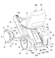
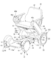
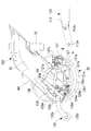
- the electric mobility has a mobility main body 30 as shown in FIGS. 1 to 3, and the mobility main body 30 is supported by a pair of front wheels 10, a pair of rear wheels 20, and a front wheel 10 and a rear wheel 20.
- the electric mobility includes a seat unit 40 that is detachably attached to the mobility main body 30, and a motor 50 that is attached to the mobility main body 30 and drives at least one of the pair of front wheels 10 and the pair of rear wheels 20.
- the vehicle front-rear direction may be referred to as the front-rear direction
- the vehicle width direction may be referred to as the width direction.
- a motor 50 is connected to each of the pair of rear wheels 20, and the two rear wheels 20 can be driven by each motor 50.
- You may comprise so that the driving force of the motor 50 may be transmitted to a pair of front wheels 10 via power transmission means, such as a belt and a gear.
- Each front wheel 10 is supported by the body 31 via an axle, a suspension, etc. (not shown).
- Each front wheel 10 has a ground contact surface formed by a plurality of rollers 13 and 14 arranged in the circumferential direction.
- the outer shape of the roller 13 is smaller than the outer shape of the roller 14, and the roller 13 and the roller 14 are alternately arranged in the circumferential direction.
- each front wheel 10 includes a hub 15 attached to the axle, and a plurality of roller support shafts arranged in the circumferential direction of the hub 15 and supported by the hub 15, respectively. Each is rotatably supported on a roller spindle.
- the hub 15 may be directly attached to the axle via a bearing or the like, or may be attached to the axle via a buffer member or other intermediate member.
- each of the rollers 13 and 14 can rotate around an axis extending in a direction intersecting the radial direction of the axle, and each front wheel 10 can move in all directions with respect to the ground plane. It is a moving wheel.
- each rear wheel 20 is provided on an axle (may be common with the main shaft of the motor 50), a hub 22 attached to the axle, and an outer peripheral side of the hub 22, and the outer peripheral surface has rubber-like elasticity.
- the outer peripheral member 23 is made of a material, an omnidirectional moving wheel may be used similarly to the front wheel 10.
- each front wheel 10 may be the same wheel as the rear wheel 10.
- each front wheel 10 may be the same wheel as the rear wheel 20, and means for changing the steering angle of the front wheel 10 and / or the rear wheel 20 may be provided.
- the mobility main body 30 includes a front wheel side vehicle body 110 and a rear wheel side vehicle body 120 that is detachably connected to the front wheel side vehicle body 110.
- the front wheel side vehicle body 110 is formed so as to extend along the ground, and is provided so as to cover at least a part of the front wheel side frame 111 and the front wheel side frame 111 to which the axle of the front wheel 10 is attached.
- a front wheel side cover 110a used for protection, a part on which a foot of a passenger sitting on the seat unit 40 is placed, a luggage placing part, mudguard and the like.
- the front wheel side frame 111 is made of a material suitable for obtaining strength, such as metal.
- the first to third cross members 113a to 113c extend in the vehicle width direction and connect the pair of side members 112 to each other.
- a first cross member (first front engaging portion) 113a is provided at a rear end portion of the pair of side members 112, and a second cross member (second front side engaging portion) is provided.
- the joint portion 113b is disposed on the vehicle front side with respect to the first cross member 113a.
- the rear wheel side body 120 supports the motor 50 and the rear wheel 20 on both sides in the vehicle width direction, and the rear wheel side frame 121 that supports the seat unit 40 on the upper end side, and at least a part of the rear wheel side frame 121.
- the rear wheel side cover 120a is provided so as to cover and used for protection of the rear wheel side frame 121, mudguard and the like.
- the rear wheel side frame 121 is made of a material suitable for obtaining strength such as metal, and as shown in FIGS. 3 and 5, for example, a lower member 122 having a pair of side members 122a extending in the front-rear direction.
- a pair of motor fixing portions 123 in the vehicle width direction to which the motor 50 to which the rear wheel 20 is attached is fixed, and a pair of motor fixing portions 123 extending in the vehicle width direction and connecting the pair of motor fixing portions 123 to each other.
- each fall prevention member 126 includes a metal tilting member 126a supported at one end side by the rear wheel side frame 121 and tiltable in the vertical direction, and an auxiliary wheel 126b rotatably supported at the other end of the tilting member 126a.
- One end side of the fall prevention member 126 is supported by the rear wheel side frame 121 and can be tilted in the vertical direction, and the auxiliary wheel 126b as the other end portion protrudes rearward of the pair of rear wheels 20.
- the pair of fall prevention members 126 are connected to each other by the connecting member 126c, whereby the pair of fall prevention members 126 are tilted together in the vertical direction.
- a seat support portion 33 for supporting the seat unit 40 is formed on the body 31 by the support portion frame 125 and a portion of the rear wheel side cover 120a that covers the support portion frame 125.
- the support portion frame 125 is inclined forward of the vehicle from the lower end side toward the upper end side. Therefore, the seat support portion 33 is also inclined forward of the vehicle from the lower end side toward the upper end side. Since the support part frame 125 has such a shape, the center of gravity of the rear wheel side vehicle body 120 is disposed in front of the vehicle with respect to the rotational axis 20a of the rear wheel 20 to such an extent that the center of gravity can be clearly seen.
- the seat support portion 33 has a front surface 33a, a back surface 33b, and a pair of side surfaces 33c disposed between the front surface 33a and the back surface 33b.
- a handle portion 125 c is integrally provided on the upper end side of the support portion frame 125, and the handle portion 125 c protrudes from the upper end side of the back surface 33 b of the seat support portion 33. It is preferable that the position of the handle portion 125c to be gripped by the hand is arranged in front of the rotation axis 20a of the rear wheel 20 of the rear wheel side vehicle body 120 connected to the front wheel side vehicle body 110.
- a rechargeable battery BA is detachably attached to the seat support 33.
- the front surface 33a and the rear surface 33b of the seat support portion 33 are inclined forward from the lower end side toward the upper end side, and an opening portion of an accommodation space 33d for accommodating the battery BA is provided on the rear surface 33b.
- a control unit 60 described later is disposed in the seat support portion 33.
- the seat mounting member 32 is a member having a longitudinal length, and is provided with a plurality of positioning holes 32a spaced in the vertical direction. Each positioning hole 32a penetrates the seat mounting member 32 in a direction orthogonal to the longitudinal direction thereof.
- a cylindrical portion 125a through which the seat mounting member 32 is inserted in the vertical direction is provided on the upper end side of the support portion frame 125, and a support portion side hole 125b penetrating in the front-rear direction is provided in the cylindrical portion 125a.
- the inner shape of the cylindrical portion 125 a is slightly larger than the outer shape of the seat mounting member 32.
- the seat mounting member 32 is inserted into the cylindrical portion 125a, and any positioning hole 32a and the support portion side hole 125b are aligned, and the positioning member 32b is inserted into the support portion side hole 125b and the positioning hole 32a.
- the seat attachment member 32 is attached by attaching to the cylindrical part 125a. Further, by changing the positioning hole 32a through which the positioning member 32b is inserted, the height position of the seat mounting member 32 relative to the mobility main body 30, that is, the height position of the seat unit 40 can be adjusted.
- the seat unit 40 is fixed under the seat surface portion 41, the backrest portion 42, the pair of control arms 43 in the vehicle width direction, and the seat surface portion 41, and is attached to and detached from the seat mounting member 32 of the seat support portion 33. And a seating frame 44 that can.
- An operation portion 43a having an operation lever 43b is provided at the upper end of the right control arm 43.
- the operation lever 43b is moved by a biasing member (not shown) disposed in the operation portion 43a. It is arranged at the neutral position, and the rider can displace the operation lever 43b in the right direction, the left direction, the front direction, and the rear direction with respect to the neutral position with the right hand.
- a signal corresponding to the displacement direction and displacement amount of the operation lever 43b is transmitted from the operation unit 43a to the control unit 60 described later, and each motor 50 is driven according to the signal.
- the operation lever 43b is displaced in the forward direction with respect to the neutral position
- a signal for rotating each motor 50 toward the front of the vehicle is transmitted, and the electric mobility advances at a speed corresponding to the displacement amount of the operation lever 43b.
- the operation lever 43b is displaced diagonally left forward with respect to the neutral position, a signal for rotating the left motor 50 toward the front of the vehicle at a slower speed than the right motor 50 is transmitted, and the electric mobility is operated by the operation lever.
- the vehicle advances while turning left at a speed corresponding to the amount of displacement 43b.
- the upper end of the left control arm 43 is provided with a setting unit 43c capable of performing various settings related to electric mobility such as maximum speed setting, operation mode setting, electric mobility lock setting, and the like. Operating buttons, a display device and the like are provided.
- the driving mode an energy saving driving mode that suppresses power consumption, a sports driving mode that emphasizes driving performance without reducing power consumption, a normal driving mode between the energy saving driving mode and the sports driving mode, etc.
- Examples of the setting of electric mobility lock include setting of a personal identification number for locking, setting of unlock timing, and the like.
- the setting signal of the setting unit 43c is transmitted to the control unit 60 described later, and the setting of the electric mobility is registered or changed in the control unit 60.
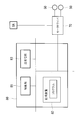
- the control unit 60 includes a motor driver 70 that drives each motor 50 and a control device 80.
- the motor driver 70 is connected to the battery BA through a power line and is connected to each motor 50 through a power line, and drives each motor 50 by supplying power.
- the control device 80 includes, for example, a control unit 81 having a CPU, a RAM, a storage device 82 having a nonvolatile memory, a ROM, and the like, and a transmission / reception unit 83.
- the storage device 82 stores a program for controlling the electric mobility.
- the control unit 81 operates based on the program, and drives each motor 50 based on signals from the operation unit 43a and the setting unit 43c. A drive signal is transmitted to the motor driver 70.
- each side member 122a of the rear wheel side frame 121 has a substantially U-shaped first recess (first rear engagement portion) 121a that opens toward the front of the vehicle. And a substantially U-shaped second recess (second rear engagement portion) 121b that is disposed in front of the vehicle relative to the first recess 121a and opens downward is formed. .
- the first recess 121a is engaged with the first cross member 113a of the front wheel side frame 111
- the second recess 121b is engaged with the second cross member 113b of the front wheel side frame 111 (See FIG. 9).
- the front wheel side frame 111 is in a state where the rear wheel side vehicle body 120 is tilted rearward around the rotation axis 20 a of the rear wheel 20 rather than being connected to the front wheel side vehicle body 110.
- the first cross member 113a is placed in the pair of first recesses 121a. In this state, each of the first recesses 121a is opened obliquely upward, so that the first cross member 113a of the front wheel side vehicle body 110 is difficult to drop off from the first recess 121a.
- the second cross member 113 b of the front wheel side frame 111 is paired with a pair. It enters the second recess 121b from below. Accordingly, the vertical movement of the first cross member 113a with respect to the rear wheel side frame 121 is restricted by the pair of side surfaces 121c of the first recess 121a shown in FIG. 11, and the rear wheel side of the second cross member 113b. The upward movement with respect to the frame 121 is restricted by the bottom surface 121f of the second recess 121b shown in FIG.
- the movement in the front-rear direction with respect to the rear wheel side frame 121 of the second cross member 113b is performed by the pair of side surfaces 121e (see FIG. 11) of the second recess 121b, or by the pair of side surfaces 121e of the second recess 121b and later.
- the connection lock member 127 is regulated. In this way, the front wheel side vehicle body 110 and the rear wheel side vehicle body 120 are connected. Note that the backward movement of the first cross member 113a relative to the rear wheel side frame 121 is also restricted by the bottom surface 121d of the first recess 121a.
- the rear wheel side frame 121 is provided with a connecting lock member 127 that tilts around a tilt axis 127c extending in the vehicle width direction.
- One end side of the connection lock member 127 is supported by one of the pair of side members 122a, the plurality of cross members 124a to 124c, the support portion frame 125, etc., and the connection lock member 127 tilts around the tilt axis 127c.
- the connection lock member 127 is disposed on the inner side in the vehicle width direction than the pair of second recesses 121b provided in the pair of side members 122a in the vehicle width direction.
- the connecting lock member 127 is urged by an urging member 127d such as a torsion spring so that the other end tilts backward. Further, when the connecting lock member 127 is tilted rearward by the biasing member 127d, a part of the connecting lock member 127 or a member fixed to the connecting lock member 127 comes into contact with a part of the rear wheel side frame 121, and The connection lock member 127 is configured not to tilt to the rear side of the vehicle with respect to the contact position.
- an urging member 127d such as a torsion spring
- the connecting lock member 127 is formed with a protruding portion 127a that protrudes rearward, and when the connecting lock member 127 is tilted rearward by the biasing member 127d and disposed at the lock position A indicated by the solid line in FIG.
- the protrusion 127a is configured to come into contact with the second cross member 113b entering the second recess 121b from below. For this reason, the engagement between the second cross member 113b and the second recess 121b is maintained by the connection lock member 127. That is, the connection between the front wheel side vehicle body 110 and the rear wheel side vehicle body 120 is maintained by the connection lock member 127.
- a part of the protrusion 127a (a part at the rear of the vehicle) is located at the rear of the pair of side surfaces 121e of the second recess 121b. It arrange
- connection lock member 127 has an inclined surface 127b that is inclined rearward from the bottom upward when the front wheel body 110 and the rear wheel body 120 are connected. Is provided. Then, when the rear wheel side vehicle body 120 is tilted forward of the vehicle around the rotation axis 20a of the rear wheel 20 with the first cross member 113a of the front wheel side frame 111 being in the pair of first recesses 121a, The second cross member 113b is configured to contact the inclined surface 127b from below (see FIG. 10).
- the connecting lock member 127 tilts forward of the vehicle against the urging force of the urging member 127d, whereby the second cross member 113b becomes the second cross member 113b.
- the connecting lock member 127 is tilted rearward by the biasing member 127d, and the front wheel side vehicle body 110 and the rear wheel side vehicle body 120 are moved by the connection lock member 127. The connection with is maintained.
- Each tilting member 126a is provided with a member engaging portion 126e that engages the cross member 124a from above, behind the vehicle, or from below. Further, on each tilting member 126a, the other end side of the member engaging portion 126e is engaged with an engaging pin 128a provided at one end portion of the tilting lock member (first restricting means) 128 from above or from the rear of the vehicle.
- a lock member engaging portion 126f is provided.
- each tilt lock member 128 is supported by the rear wheel side frame 121 and can be tilted around a tilt axis 128b extending in the vehicle width direction, and an engagement pin 128a is provided at one end (lower end).
- an engagement pin 128a is provided at one end (lower end).
- the lock member engaging portion 126f of the fall-preventing member 126 is engaged with the cross member (second restricting means) 124a from above or from the rear of the vehicle. Tilt to is regulated.
- tilting of the fall prevention member 126 below the third tilt position may be restricted.
- the second tilt position is above the first tilt position
- the third tilt position is equivalent to or slightly below the first tilt position.
- One end of a plate-like link member 129 is connected to the other end of the tilt lock member 128, and the other end of the link member 129 is connected to a position away from the tilt axis 127c of the connection lock member 127. .
- the engagement pin 128 a is engaged with the lock member engagement portion 126 f in a state where the connection lock member 127 is disposed at the lock position A, or is disposed at an engageable position.
- the engagement pin 128a and the lock member engagement portion 126f are not engaged.
- the other end of the tilt lock member 128 is connected to one end of an operation lever 130 as an operation means, and the operation lever 130 tilts around the tilt axis 128 b of the tilt lock member 128.
- the other end of the operation lever 130 protrudes from the rear wheel side cover 120a of the rear wheel body 120, so that the operation lever 130 is tilted rearward or downward to engage the engagement lever 130.
- the engagement between the coupling pin 128a and the lock member engagement portion 126f can be released, and the connection lock member 127 can be disposed at the retracted position B.
- the position of the center of gravity of the rear wheel side vehicle body 120 is disposed between or near the ground contact position of the rear wheel 20 and the ground contact position of the auxiliary wheel 126b of the fall prevention member 126 in the vehicle longitudinal direction. It is preferable. As a result, the rear wheel side vehicle body 120 is stably supported by the rear wheel 20 and the overturn prevention member 126.
- each first recess 121a is opened obliquely upward, so that the first cross member 113a of the front wheel side vehicle body 110 is stably in the first recess 121a. Supported. Therefore, the front wheel side vehicle body 110 is removed from the first recess 121a by releasing the handle 125c, lifting the rear end side of the front wheel side vehicle body 110, and pulling out the first cross member 113a from the first recess 121a. Can be removed from. Also at this time, the rear wheel side vehicle body 120 is stably supported by the rear wheel 20 and the fall prevention member 126. After being disassembled in this way, the front wheel side vehicle body 110 and the rear wheel side vehicle body 120 are loaded on an automobile or the like.
- the auxiliary wheel 126b and the rear wheel 20 of the fall prevention member 126 are grounded in a state where the fall prevention member 126 is disposed at the second tilt position.
- the first cross member 113a of the front wheel side vehicle body 110 is inserted into the first recess 121a.
- the front wheel side vehicle body 10 is supported by the first recess 121a and the front wheel 110.
- the rear wheel body 120 is tilted forward around the axle of the rear wheel 20.
- the second cross member 113 b comes into contact with the inclined surface 127 b of the connection lock member 127 from below.
- the connecting lock member 127 tilts forward of the vehicle, whereby the second cross member 113b is moved into the second recess 121b. enter.
- the connecting lock member 127 is tilted rearward by the biasing member 127d, and the front wheel side vehicle body 110 and the rear wheel side vehicle body 120 are moved by the connection lock member 127. The connection with is maintained.
- the fall prevention member 126 tilts to the second tilt position above the first tilt position. At this position, the upward tilting is restricted by the cross member 124a. For this reason, when the auxiliary wheel 126b of the fall prevention member 126 is grounded, the position of the center of gravity of the rear wheel-side vehicle body 120 moves to the rear of the vehicle. For example, the position of the center of gravity is the grounding part of the rear wheel 20 and the grounding part of the auxiliary wheel 126b.
- the rear wheel side vehicle body 120 can be stably supported by the rear wheel 20 and the toppling prevention member 126.
- connection lock member 127 when the connection lock member 127 is moved to the retracted position B by the operation lever 130 and the connection lock between the front wheel side vehicle body 110 and the rear wheel side vehicle body 120 is released, the tilting by the tilt lock member 128 is performed.
- the overturn prevention member 126 is tilted to the second tilt position above the first tilt position, and the tilting upward is regulated by the cross member 124a at that position. For this reason, when the connection release operation is performed, the rear wheel body 120 can be stably supported by the rear wheel 20 and the fall-preventing member 126, which is advantageous in facilitating the connection release operation. It is.
- the link lock member 129 also tilts the link lock member 127. Therefore, the tilt restriction by the tilt lock member 128 is released in conjunction with the release operation of the connection, and the rear wheel side vehicle body 120 can be stably and stably supported by the rear wheel 20 and the fall prevention member 126. Can be in a state.
- the operation lever 130 may be fixed to the connection lock member 127, and when the connection lock member 127 is tilted, the tilt lock member 128 may also be tilted by the link member 129.
- a fall prevention member 126 that is disposed at the first tilt position and prevents the electric mobility from falling backward is provided between the front wheel side vehicle body 110 and the front wheel side vehicle body 110. Since it is used to support the rear wheel side vehicle body 120 that has been released from the connection, there is no need to provide a dedicated member for supporting the rear wheel side vehicle body 120.
- the tilting restriction state by the tilting lock member 128 and the locking state by the connecting lock member 127 are physically confirmed. can do. For this reason, unreasonable operations such as tilting the rear wheel side vehicle body 120 rearward in a state where the tilting restriction by the tilting lock member 128 and the lock by the connecting lock member 127 are not released are prevented.
- the front wheel side vehicle body 110 and the rear wheel side vehicle body 120 are connected, the state of tilt restriction by the tilt lock member 128 and the state of lock by the connection lock member 127 can be physically confirmed.
- the downward tilt of the fall prevention member 126 is restricted by the cross member 124a of the rear wheel side frame 121. Further, even when the restriction of the tilting by the tilt lock member 128 is released and the tipping prevention member 126 is tilted to the second tilting position, the upward tilting of the tipping prevention member 126 is restricted by the same cross member 124a. For this reason, the configuration for controlling the tilting of the fall prevention member 126 can be simplified, which is advantageous in electric mobility where there is a strong demand for weight reduction and design space is limited.
- the tilting lock member 128 and the connecting lock member 127 are tilted by the operation lever 130.
- the output shaft of the speed reducer is connected to at least one of the tilting lock member 128 and the connecting lock member 127.
- the drive shaft of the speed reducer can be configured to be driven by a motor.
- the control device 80 may be configured to control the motor 50 based on the lock release signal or the lock signal received by the control device 80.
- the seat unit 40 is disassembled into the front wheel side vehicle body 110 and the rear wheel side vehicle body 120 after being removed from the mobility main body 30.
- the seat unit 40 is attached to the front wheel side vehicle body 110 instead of the rear wheel side vehicle body 120, or when the seat unit 40 is small, it may not be necessary to remove the seat unit 40.
- the fall prevention member 126 protrudes rearward of the rear wheel 20 and tilts the fall prevention member 126 upward so that the auxiliary wheel 126b and the rear wheel 20 at the other end of the fall prevention member 126
- the support for the rear wheel side vehicle body 120 is shown.
- the fall prevention member 126 may be configured without the auxiliary wheel 126b. Even in this case, the fall prevention member 126 can prevent the electric mobility from falling backward, and the rear wheel side vehicle body 120 can be supported by the other end portion of the fall prevention member 126 and the rear wheel 20.
- the fall prevention member 126 when the center of gravity of the rear wheel side vehicle body 120 is located behind the rotation axis 20a of the rear wheel 20, the fall prevention member 126 is located above the first tilt position.
- one end of the projecting member is supported by the rear wheel side vehicle body 120 and can be tilted in the vertical direction. Further, in a connected state of the front wheel side vehicle body 110 and the rear wheel side vehicle body 120, the projecting member is disposed at the first tilt position so as to extend in the vehicle longitudinal direction, for example. When the connection between the front wheel side vehicle body 110 and the rear wheel side vehicle body 120 is released, or after that, the projecting member can be tilted to a second tilt position that is higher than the first tilt position. As a result, when the rear wheel side vehicle body 120 is supported by the other end portion of the protruding member and the rear wheel 20, the position of the center of gravity of the rear wheel side vehicle body 120 moves forward of the vehicle as compared with the connection.
- the rear wheel side frame 121 is provided with a cross member, an engagement pin, etc. extending in the vehicle width direction instead of the first recess 121a, and each side member 112 of the front wheel side frame 111 is replaced with the first cross member 113a.
- a substantially U-shaped recess opening obliquely downward toward the front of the vehicle may be provided, and the recess may be configured such that a cross member, an engagement pin, or the like of the rear wheel side frame 121 is engaged with each recess.
- each side member 112 of the front wheel side frame 111 is replaced with the second cross member 113b.
- a substantially U-shaped recess that opens upward may be provided, and a cross member, an engagement pin, and the like of the rear wheel side frame 121 may be engaged with each recess.
- the front wheel side vehicle body 110 and the rear wheel side vehicle body 120 may be configured to be detachably connected by other methods.
- the first recess 121a contacts the first cross member 113a from below, above, and from the rear of the vehicle when the front wheel side vehicle body 110 and the rear wheel side vehicle body 120 are connected, and opens to the front of the vehicle. If it exists, even if it is another shape, there exists an effect similar to the above-mentioned.
- the second recess 121b is also configured so as to contact the second cross member 113b from the upper side, the rear side of the vehicle, and the front side of the vehicle when the front wheel side vehicle body 110 and the rear wheel side vehicle body 120 are connected, and open downward. Even in other shapes, the same effects as described above can be obtained.
- the front wheel side frame 111 when the front wheel side frame 111 is provided with a recess opening obliquely downward toward the front of the vehicle instead of the first cross member 113a, the front wheel side vehicle body 110 and the rear wheel side vehicle body 120 are connected. As long as it is in contact with the cross member, engagement pin, etc. of the rear wheel side vehicle body 120 from above, below, and from the rear of the vehicle and opens obliquely downward toward the front of the vehicle, it is the same as described above even in other shapes Has the effect of.
- the rear wheel side vehicle body 110 is connected when the front wheel side vehicle body 110 and the rear wheel side vehicle body 120 are connected. Any other shape can be obtained as long as it is in contact with 120 cross members, engagement pins, etc. from below, the rear of the vehicle, and the front of the vehicle and opens upward.
- the locking member engaging portion 126f of the tilting member 126a is engaged with the cross member 124a so that the tilting of the tipping prevention member 126 is restricted from being tilted upward from the second tilting position. Indicated.
- a part between the other end portion of the tilting member 126a and the tilting center 126d is engaged with the rear wheel side cover 120a and the rear wheel side frame 121, thereby the second tilting position of the fall prevention member 126. Further upward tilting may be restricted.
- the tilting of the fall-preventing member 126 upward from the second tilt position may be restricted by another structure.
Landscapes
- Health & Medical Sciences (AREA)
- Life Sciences & Earth Sciences (AREA)
- Animal Behavior & Ethology (AREA)
- General Health & Medical Sciences (AREA)
- Public Health (AREA)
- Veterinary Medicine (AREA)
- Engineering & Computer Science (AREA)
- Mechanical Engineering (AREA)
- Automatic Cycles, And Cycles In General (AREA)
- Electric Propulsion And Braking For Vehicles (AREA)
- Motorcycle And Bicycle Frame (AREA)
Abstract
この電動モビリティは、前輪側車体(110)と、前輪側車体(110)に取外し可能に連結された後輪側車体(120)と、後輪側車体(120)に一端側が支持されて上下方向に傾動可能であり、後輪側車体(120)に設けられた車両幅方向一対の後輪(20)の外周面よりも他端部が車両後方に突出している突出部材(126)と、第1の傾動位置よりも上方に傾動しないように突出部材の傾動規制を行う傾動ロック部材(128)と、第1の傾動位置に比べ上方である第2の傾動位置よりも上方に傾動しないように突出部材の傾動規制を行うクロスメンバ(124a)と、傾動ロック部材(128)による傾動規制を解除可能な操作手段とを備えている。
Description
本発明は電動モビリティおよびその分解方法に関する。
このような電動モビリティとして、取外し可能なシートと、前輪側車体と、後輪側車体とに分解可能であり、後輪側車体は単体で後輪の軸周りに回動して後傾姿勢となるような重量配分を有すると共に、後輪よりも後方に突出している突出部材(補助輪)を有し、前輪側車体から取外されると、後輪側車体が後傾して突出部材と後輪とにより支持されるものが知られている(例えば、特許文献1参照。)。
また、取外し可能なシートと、取外し可能なバッテリと、前輪側車体と、後輪側車体とに分解可能であり、後輪側車体は後輪よりも後方に突出している突出部材(転倒防止棒)を有し、前輪側車体から取外された時に、後輪側車体が後傾して突出部材と後輪とにより支持される電動モビリティが知られている(例えば、特許文献2参照。)。
前記2つの電動モビリティは、後輪側車体の重心を後輪の回転軸線よりも後側に配置しなければ、突出部材と後輪とにより後側車体を安定して支持することができないので、後輪側車体の設計の自由度が低くなる。
本発明は、このような事情に鑑みてなされたものであって、後輪側車体を前輪側車体から取外した後に、後輪よりも突出している突出部材と後輪とにより後輪側車体を安定して支持することができ、しかも後輪側車体の設計の自由度を向上することができる電動モビリティおよびその分解方法の提供を目的とする。
上記課題を解決するために、本発明は以下の手段を採用する。
本発明の第1の態様の電動モビリティは、前輪側車体と、該前輪側車体に取外し可能に連結された後輪側車体と、該後輪側車体に一端側が支持されて上下方向に傾動可能であり、該後輪側車体に設けられた後輪の外周面よりも他端部が車両前方又は車両後方に突出している突出部材と、第1の傾動位置よりも上方に傾動しないように前記突出部材の傾動規制を行う第1の規制手段と、前記第1の傾動位置に比べ上方である第2の傾動位置よりも上方に傾動しないように前記突出部材の傾動規制を行う第2の規制手段と、前記第1の規制手段による前記傾動規制を解除可能な操作手段とを備えている。
本発明の第1の態様の電動モビリティは、前輪側車体と、該前輪側車体に取外し可能に連結された後輪側車体と、該後輪側車体に一端側が支持されて上下方向に傾動可能であり、該後輪側車体に設けられた後輪の外周面よりも他端部が車両前方又は車両後方に突出している突出部材と、第1の傾動位置よりも上方に傾動しないように前記突出部材の傾動規制を行う第1の規制手段と、前記第1の傾動位置に比べ上方である第2の傾動位置よりも上方に傾動しないように前記突出部材の傾動規制を行う第2の規制手段と、前記第1の規制手段による前記傾動規制を解除可能な操作手段とを備えている。
当該態様では、操作手段により第1の規制手段による傾動規制が解除されると、突出部材が第1の傾動位置よりも上方の第2の傾動位置に傾動し、その位置で第2の規制手段により上方への傾動が規制される。
例えば、第1の規制手段による傾動規制が行われた状態で、後輪側車体が前輪側車体に連結された状態で突出部材の他端部が後輪よりも車両後方の地面の近傍に位置しており、後輪側車体の重心が後輪の回転軸線よりも車両前方に位置している場合は、突出部材の他端部を接地させても、重心の位置が後輪の接地部と突出部材の他端部との間に配置されないので、後輪側車体を後輪および突出部材により安定して支持することができない。
例えば、第1の規制手段による傾動規制が行われた状態で、後輪側車体が前輪側車体に連結された状態で突出部材の他端部が後輪よりも車両後方の地面の近傍に位置しており、後輪側車体の重心が後輪の回転軸線よりも車両前方に位置している場合は、突出部材の他端部を接地させても、重心の位置が後輪の接地部と突出部材の他端部との間に配置されないので、後輪側車体を後輪および突出部材により安定して支持することができない。
これに対し、当該態様では、操作手段により突出部材を第1の傾動位置よりも上方の第2の傾動位置に傾動させ、突出部材の他端部を接地させると、後輪側車体の重心の位置が車両後方に移動し、例えば重心の位置を後輪の接地部と突出部材の他端部との間に配置し、後輪側車体を後輪および突出部材により支持することが可能となる。後輪側車体が前輪側車体に連結された状態で突出部材の他端部が後輪よりも車両前方の地面の近傍に位置しており、後輪側車体の重心が後輪よりも車両前方の地面の近傍に位置している場合も同様である。
上記態様において、前記後輪側車体に設けられ、前記前輪側車体と前記後輪側車体との連結を維持するロック位置および該連結を解除可能な状態とする退避位置に移動可能な連結ロック部材をさらに備え、前記操作手段を操作すると前記連結ロック部材が前記ロック位置から前記退避位置に移動するように構成されており、前記操作手段の操作により前記連結ロック部材を前記ロック位置から前記退避位置に移動させる時に、前記第1の規制手段による前記傾動規制が解除されるように構成することが好ましい。
この場合、操作手段により連結ロック部材を退避位置に移動させて前輪側車体と後輪側車体との連結のロックを解除した際に、第1の規制手段による傾動規制が解除され、突出部材が第1の傾動位置よりも上方の第2の傾動位置に傾動し、その位置で第2の規制手段により上方への傾動が規制される。このため、連結の解除操作を行う時に、後輪側車体が後輪と突出部材とにより支持可能な状態になるため、連結の解除操作を容易化する上で有利である。
上記態様において、前記第1の規制手段が、前記第1の傾動位置で前記突出部材に係合して前記傾動規制を行う傾動ロック部材であり、前記連結ロック部材の前記ロック位置から前記退避位置への移動と、前記傾動ロック部材の前記突出部材に係合する位置から前記突出部材との係合が解除される位置への移動とを連動させるリンク機構をさらに備えることが好ましい。
この場合、連結ロック部材および傾動ロック部材の一方を傾動させると、リンク機構により他方も傾動するので、連結の解除操作を行う時に第1の規制手段による傾動規制が連動して解除され、容易且つ確実に後輪側車体を後輪と突出部材とにより安定して支持可能な状態にすることができる。
上記態様において、前記突出部材が、前記第1の傾動位置に配置された時に該電動モビリティの後方への転倒を防止するものであることが好ましい。
この場合、電動モビリティの後方への転倒を防止する突出部材を用いて、前輪側車体との連結を解除した後の後輪側車体を安定して支持することができるので、後輪側車体を支持するための専用の部材を設ける必要がない。
この場合、電動モビリティの後方への転倒を防止する突出部材を用いて、前輪側車体との連結を解除した後の後輪側車体を安定して支持することができるので、後輪側車体を支持するための専用の部材を設ける必要がない。
上記態様において、前記操作手段が前記後輪側車体に設けられた傾動可能な操作レバーであり、該操作レバーの傾動により前記連結ロック部材および前記傾動ロック部材の一方が操作されると共に、他方が前記リンク機構を介して操作されるように構成されていることが好ましい。
この場合、操作レバーの傾動状態を確認することにより、第1の規制手段による傾動規制の状態および連結ロック部材によるロックの状態を物理的に確認することができるので、第1の規制手段による傾動規制や連結ロック部材によるロックが解除されていない状態で後輪側車体を後傾させる等の無理な操作が防止される。また、前輪側車体と後輪側車体とを連結する時も、第1の規制手段による傾動規制の状態および連結ロック部材によるロックの状態を物理的に確認することができる。
上記態様において、前記後輪側車体を構成する所定のフレームと接触することにより、前記第1の傾動位置よりも下方又は前記第1の傾動位置よりも下方である第3の傾動位置よりも下方への前記突出部材の傾動が規制され、前記所定のフレームと接触することにより、前記第2の傾動位置よりも上方への前記突出部材の傾動が規制されることが好ましい。
この場合、第1の規制手段により上方への傾動が規制された状態で、突出部材の下方への傾動が所定のフレームにより規制され、第1の規制手段による傾動の規制が解除され、突出部材が第2の傾動位置に傾動した際にも、同じフレームにより突出部材の上方への傾動が規制される。このため、突出部材の傾動を制御するための構成をシンプルにすることができ、これは重量低減に関する強い要求があり設計スペースが限られている電動モビリティにおいて有利である。
本発明の第2の態様は、前輪側車体から後輪側車体を取外し可能な電動モビリティの分解方法であって、前記後輪側車体が、突出部材と、第1の規制手段とを備えるものであり、前記突出部材は、前記後輪側車体に一端側が支持されて上下方向に傾動可能であり、また、前記突出部材の他端部は、前記後輪側車体に設けられた後輪の外周面よりも車両前方又は車両後方に突出しており、前記第1の規制手段は、第1の傾動位置よりも上方に傾動しないように前記突出部材の傾動規制を行うものであり、前記第1の規制手段による前記傾動規制を解除して前記突出部材を前記第1の傾動位置よりも上方の第2の傾動位置まで傾動させるステップと、該第2の傾動位置に配置された前記突出部材の他端部を接地させ、該他端部と前記後輪とにより前記後輪側車体を支持するステップと、を有する。
例えば、第1の規制手段による傾動規制が行われた状態で、後輪側車体が前輪側車体に連結された状態で突出部材の他端部が後輪よりも車両後方の地面の近傍に位置しており、後輪側車体の重心が後輪の回転軸線よりも車両前方に位置している場合は、突出部材の他端部を接地させても、重心の位置が後輪の接地部と突出部材の他端部との間に配置されないので、後輪側車体を後輪および突出部材により安定して支持することができない。
これに対し、当該態様では、突出部材を第1の傾動位置よりも上方の第2の傾動位置に傾動させ、突出部材の他端部を接地させると、後輪側車体の重心の位置が車両後方に移動し、例えば重心の位置を後輪の接地部と突出部材の他端部との間に配置し、後輪側車体を後輪および突出部材により支持することが可能となる。後輪側車体が前輪側車体に連結された状態で突出部材の他端部が後輪よりも車両前方の地面の近傍に位置しており、後輪側車体の重心が後輪の回転軸線よりも車両前方の地面の近傍に位置している場合も同様である。
本発明によれば、後輪側車体を前輪側車体から取外した後に、後輪よりも突出している突出部材と後輪とにより後輪側車体を安定して支持することができ、しかも後輪側車体の設計の自由度を向上することができる。
本発明の一実施形態に係る電動モビリティを図面を参照して以下に説明する。
この電動モビリティは、図1~図3に示すように、モビリティ本体30を有し、モビリティ本体30は、一対の前輪10と、一対の後輪20と、前輪10および後輪20により支持されたボディ31とを有する。また、この電動モビリティは、モビリティ本体30に着脱自在に取付けられた座席ユニット40と、モビリティ本体30に取付けられ、一対の前輪10および一対の後輪20の少なくとも一方を駆動するためのモータ50とを有する。以下の説明では、車両前後方向を前後方向と称し、車両幅方向を幅方向と称する場合がある。
この電動モビリティは、図1~図3に示すように、モビリティ本体30を有し、モビリティ本体30は、一対の前輪10と、一対の後輪20と、前輪10および後輪20により支持されたボディ31とを有する。また、この電動モビリティは、モビリティ本体30に着脱自在に取付けられた座席ユニット40と、モビリティ本体30に取付けられ、一対の前輪10および一対の後輪20の少なくとも一方を駆動するためのモータ50とを有する。以下の説明では、車両前後方向を前後方向と称し、車両幅方向を幅方向と称する場合がある。
本実施形態では、一対の後輪20にそれぞれモータ50が接続され、各モータ50によって2つの後輪20をそれぞれ駆動可能である。モータ50の駆動力がベルト、ギヤ等の動力伝達手段を介して一対の前輪10に伝達されるように構成してもよい。
各前輪10は、図示しない車軸、サスペンション等を介してボディ31に支持されている。また、各前輪10はその周方向に並ぶ複数のローラ13,14によって接地面が形成されている。ローラ13の外形はローラ14の外形よりも小さく、ローラ13とローラ14が周方向に交互に並んでいる。
各前輪10は、図示しない車軸、サスペンション等を介してボディ31に支持されている。また、各前輪10はその周方向に並ぶ複数のローラ13,14によって接地面が形成されている。ローラ13の外形はローラ14の外形よりも小さく、ローラ13とローラ14が周方向に交互に並んでいる。
より具体的に、各前輪10は、車軸に取付けられたハブ15と、ハブ15の周方向に並ぶと共にそれぞれハブ15に支持された複数のローラ支軸とを備え、複数のローラ13,14はそれぞれローラ支軸に回転可能に支持されている。なお、ハブ15は車軸にベアリング等を介して直接取付けられていてもよく、車軸に緩衝部材やその他の中間部材を介して取付けられていてもよい。
このように構成されているので、各ローラ13,14は車軸の径方向と交差する方向に延びる軸線周りに回転することができ、各前輪10は接地面に対して全方向に移動する全方向移動車輪となっている。
本実施形態では、各後輪20は、車軸(モータ50の主軸と共通でもよい)と、車軸に取付けられたハブ22と、ハブ22の外周側に設けられ、外周面がゴム状弾性を有する材料により形成された外周部材23とを有するが、前輪10と同様に全方向移動車輪を用いてもよい。この場合、各前輪10が後輪10と同様の車輪であってもよい。さらに、各前輪10を後輪20と同様の車輪にすると共に、前輪10および/又は後輪20の操舵角を変更するための手段を設けてもよい。
本実施形態では、各後輪20は、車軸(モータ50の主軸と共通でもよい)と、車軸に取付けられたハブ22と、ハブ22の外周側に設けられ、外周面がゴム状弾性を有する材料により形成された外周部材23とを有するが、前輪10と同様に全方向移動車輪を用いてもよい。この場合、各前輪10が後輪10と同様の車輪であってもよい。さらに、各前輪10を後輪20と同様の車輪にすると共に、前輪10および/又は後輪20の操舵角を変更するための手段を設けてもよい。
モビリティ本体30は、前輪側車体110と、前輪側車体110に取外し可能に連結される後輪側車体120とを有する。前輪側車体110は、地面に沿って延びるように形成され、前輪10の車軸が取付けられた前輪側フレーム111と、前輪側フレーム111の少なくとも一部を覆うように設けられ、前輪側フレーム111の保護、座席ユニット40に座る乗車者の足を載せる部分、荷物載置部、泥除け等に活用される前輪側カバー110aとを有する。
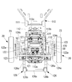
前輪側フレーム111は金属等の強度を得るのに適した材料から成り、例えば図3に示すように、それぞれ前後方向に延びる幅方向一対のサイドメンバ112と、互いに前後方向に間隔をおいて配置されると共にそれぞれ車両幅方向に延び、一対のサイドメンバ112を互いに接続する第1~第3のクロスメンバ113a~113cとを有する。複数のクロスメンバ113a~113cのうち、第1のクロスメンバ(第1の前側係合部)113aは一対のサイドメンバ112における後端部に設けられ、第2のクロスメンバ(第2の前側係合部)113bは第1のクロスメンバ113aよりも車両前側に配置されている。
後輪側車体120は、車両幅方向の両側にそれぞれモータ50および後輪20を支持し、上端側に座席ユニット40を支持する後輪側フレーム121と、後輪側フレーム121の少なくとも一部を覆うように設けられ、後輪側フレーム121の保護、泥除け等に活用される後輪側カバー120aとを有する。
後輪側フレーム121は金属等の強度を得るのに適した材料から成り、例えば図3および図5に示すように、それぞれ前後方向に延びる幅方向一対のサイドメンバ122aを有する下側部材122と、それぞれ後輪20が取付けられたモータ50が固定される車両幅方向一対のモータ固定部123と、それぞれ車両幅方向に延び、一対のモータ固定部123を互いに連結すると共に、一対のモータ固定部123を下側部材122に固定する複数のクロスメンバ124a~124cと、下端側がサイドメンバ122a、クロスメンバ124a~124c等に固定され、上端側に座席ユニット40を装着するための座席取付部材32が取付けられる支持部フレーム125とを有する(図4参照)。
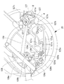
また、後輪側フレーム121には、電動モビリティの車両後方への転倒を防止するために幅方向一対の転倒防止部材(突出部材)126が設けられている。各転倒防止部材126は、一端側が後輪側フレーム121に支持され上下方向に傾動可能である金属製の傾動部材126aと、傾動部材126aの他端に回転可能に支持された補助輪126bとを有する。転倒防止部材126は一端側が後輪側フレーム121に支持され上下方向に傾動可能であり、他端部である補助輪126bが一対の後輪20よりも車両後方に突出している。また、一対の転倒防止部材126は連結部材126cにより互いに連結され、これにより一対の転倒防止部材126は一緒に上下方向に傾動する。
なお、支持部フレーム125と、後輪側カバー120aのうち支持部フレーム125を覆う部分とにより、座席ユニット40を支持するための座席支持部33がボディ31に形成されている。支持部フレーム125は下端側から上端側に向かって車両前方に傾斜しており、このため座席支持部33も下端側から上端側に向かって車両前方に傾斜している。支持部フレーム125がこのような形状を有するので、後輪側車体120の重心は明確にわかる程度に後輪20の回転軸線20aに対して車両前方に配置されている。
図1および図2に示すように、座席支持部33は前面33aと、背面33bと、前面33aと背面33bとの間に配置される一対の側面33cとを有する。支持部フレーム125の上端側には持ち手部125cが一体に設けられ、持ち手部125cは座席支持部33の背面33bの上端側から突出している。持ち手部125cにおいて手で握る位置は、前輪側車体110と連結された状態の後輪側車体120の後輪20の回転軸線20aよりも前方に配置されていることが好ましい。
また、図1および図4に示すように、座席支持部33には充電可能なバッテリBAが着脱自在に取付けられている。座席支持部33の前面33aおよび背面33bは下端側から上端側に向かって車両前方に傾斜しており、背面33bにはバッテリBAを収容するための収容スペース33dの開口部が設けられている。また、座席支持部33内には後述する制御ユニット60が配置されている。
座席取付部材32は上下方向に長手を有する部材であり、上下方向に間隔をおいて複数の位置決め孔32aが設けられている。各位置決め孔32aは座席取付部材32をその長手方向と直交する方向に貫通している。支持部フレーム125の上端側には座席取付部材32が上下方向に挿通する筒状部125aが設けられ、筒状部125aには前後方向に貫通する支持部側孔125bが設けられている。筒状部125aの内形は座席取付部材32の外形よりも若干大きい。
筒状部125aに座席取付部材32を挿入すると共に、何れかの位置決め孔32aと支持部側孔125bとを位置合わせし、支持部側孔125bおよび位置決め孔32aに挿通するように位置決め部材32bを筒状部125aに取付けることにより、座席取付部材32が取付けられる。また、位置決め部材32bを挿通させる位置決め孔32aを変更することにより、モビリティ本体30に対する座席取付部材32の高さ位置、つまり座席ユニット40の高さ位置を調整することができる。
座席ユニット40は、乗車者が座る座面部41と、背凭れ部42と、車両幅方向一対のコントロールアーム43と、座面部41の下に固定され、座席支持部33の座席取付部材32に着脱することができる座面フレーム44とを有する。
右側のコントロールアーム43の上端には操作レバー43bを有する操作部43aが設けられ、力が加えられていない状態では操作レバー43bは操作部43a内に配置された付勢部材(図示せず)により中立位置に配置されており、乗車者が右手により中立位置に対して右方向、左方向、前方向、および後方向に操作レバー43bを変位させることができる。
操作レバー43bの変位方向および変位量に応じた信号が操作部43aから後述する制御ユニット60に送信され、当該信号に応じて各モータ50が駆動される。例えば、操作レバー43bが中立位置に対し前方向に変位されると、各モータ50を車両前方に向かって回転させる信号が送信され、電動モビリティが操作レバー43bの変位量に応じた速度で前進する。また、操作レバー43bが中立位置に対し左斜め前方に変位されると、左側のモータ50を右側のモータ50よりも遅い速度で車両前方に向かって回転させる信号が送信され、電動モビリティが操作レバー43bの変位量に応じた速度で左に曲がりながら前進する。
左側のコントロールアーム43の上端には、最高速度設定、運転モード設定、電動モビリティのロックの設定等、電動モビリティに関する各種設定を行うことが可能な設定部43cが設けられ、設定部43cには複数の操作ボタン、表示装置等が設けられている。例えば、運転モードの例としては、電力の消費を抑えた省エネ運転モード、電力の消費を抑えずに走行性能を重視したスポーツ運転モード、省エネ運転モードとスポーツ運転モードとの間の通常運転モード等が挙げられる。電動モビリティのロックの設定としては、ロックをかけるための暗証番号の設定、ロック解除のタイミングの設定等が挙げられる。設定部43cの設定信号は後述する制御ユニット60に送信され、制御ユニット60において電動モビリティの設定が登録又は変更される。
制御ユニット60は、図12に示すように、各モータ50を駆動するモータドライバ70と、制御装置80とを有する。
モータドライバ70は電力線によりバッテリBAに接続されると共に、電力線により各モータ50に接続され、各モータ50に電力を供給して駆動する。
モータドライバ70は電力線によりバッテリBAに接続されると共に、電力線により各モータ50に接続され、各モータ50に電力を供給して駆動する。
制御装置80は、例えばCPU、RAM等を有する制御部81と、不揮発性メモリ、ROM等を有する記憶装置82と、送受信部83とを有する。記憶装置82には電動モビリティを制御するためのプログラムが格納されており、制御部81はプログラムに基づき動作し、操作部43aおよび設定部43cからの信号に基づき、各モータ50を駆動するための駆動信号をモータドライバ70に送信する。
次に、前輪側車体110と後輪側車体120との連結構造について説明する。
図4~図6に示すように、後輪側フレーム121の各サイドメンバ122aには、車両前方に向かって開口する略U字形状の第1の凹部(第1の後側係合部)121aが形成され、また、第1の凹部121aよりも車両前方に配置され、下方に向かって開口する略U字形状の第2の凹部(第2の後側係合部)121bが形成されている。第1の凹部121aは前輪側フレーム111の第1のクロスメンバ113aが係合するものであり、第2の凹部121bは前輪側フレーム111の第2のクロスメンバ113bが係合するものである(図9参照)。
図4~図6に示すように、後輪側フレーム121の各サイドメンバ122aには、車両前方に向かって開口する略U字形状の第1の凹部(第1の後側係合部)121aが形成され、また、第1の凹部121aよりも車両前方に配置され、下方に向かって開口する略U字形状の第2の凹部(第2の後側係合部)121bが形成されている。第1の凹部121aは前輪側フレーム111の第1のクロスメンバ113aが係合するものであり、第2の凹部121bは前輪側フレーム111の第2のクロスメンバ113bが係合するものである(図9参照)。
より具体的には、図7に示すように、前輪側車体110に連結された状態よりも後輪側車体120を後輪20の回転軸線20a周りに後傾させた状態で、前輪側フレーム111の第1のクロスメンバ113aを一対の第1の凹部121a内に入れる。この状態で、各第1の凹部121aは斜め上方に開口した状態となるので、前輪側車体110の第1のクロスメンバ113aが第1の凹部121aから脱落し難い。
続いて、図8および図9に示すように、後輪20の回転軸線20a周りに後輪側車体120を車両前方に向かって傾けると、前輪側フレーム111の第2のクロスメンバ113bが一対の第2の凹部121b内に下方から入る。これにより、第1のクロスメンバ113aの後輪側フレーム121に対する上下方向の移動が、図11に示す第1の凹部121aの一対の側面121cにより規制され、第2のクロスメンバ113bの後輪側フレーム121に対する上方への移動が、図11に示す第2の凹部121bの底面121fにより規制される。また、第2のクロスメンバ113bの後輪側フレーム121に対する前後方向の移動が第2の凹部121bの一対の側面121e(図11参照)により、又は第2の凹部121bの一対の側面121eおよび後述の連結ロック部材127により規制される。このようにして、前輪側車体110と後輪側車体120とが連結される。なお、第1のクロスメンバ113aの後輪側フレーム121に対する後方への移動も第1の凹部121aの底面121dにより規制される。
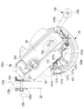
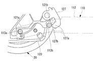
図4および図6に示すように、後輪側フレーム121には、車両幅方向に延びる傾動軸線127c周りに傾動する連結ロック部材127が設けられている。連結ロック部材127の一端側は、一対のサイドメンバ122a、複数のクロスメンバ124a~124cの何れか、支持部フレーム125等に支持され、連結ロック部材127は傾動軸線127c周りに傾動する。本実施形態では、連結ロック部材127は、車両幅方向一対のサイドメンバ122aにそれぞれ設けられた一対の第2の凹部121bよりも車両幅方向の内側に配置されている。
連結ロック部材127は、トーションスプリング等の付勢部材127dによって、他端側が後方に向かって傾動するように付勢されている。また、連結ロック部材127が付勢部材127dにより後方に向かって傾動すると、連結ロック部材127の一部又は連結ロック部材127に固定された部材が後輪側フレーム121の一部に当接し、当該当接位置よりも車両後側に連結ロック部材127が傾動しないように構成されている。
連結ロック部材127には後方に突出する突出部127aが形成され、付勢部材127dにより連結ロック部材127が後方に向かって傾動し、図6に実線で示すロック位置Aに配置されると、前述のように第2の凹部121bに入った第2のクロスメンバ113bに突出部127aが下方から当接するように構成されている。このため、第2のクロスメンバ113bと第2の凹部121bとの係合が連結ロック部材127により維持される。つまり、連結ロック部材127により前輪側車体110と後輪側車体120との連結が維持される。連結ロック部材127がロック位置Aに配置された時、図11に示すように、突出部127aの一部(車両後方の一部)が第2の凹部121bの一対の側面121eのうち車両後方の側面121eよりも車両後方に配置される。
一方、連結ロック部材127が車両前方に傾動し、図6に示す退避位置Bに配置されると、第2のクロスメンバ113bに突出部127aが当接しない状態となり、前輪側車体110と後輪側車体120との連結を解除可能な状態、又は解除された状態となる。
また、連結ロック部材127の他端側における車両後側の面には、前輪側車体110と後輪側車体120とが連結された状態において下から上に向かって車両後方に傾斜する傾斜面127bが設けられている。そして、前輪側フレーム111の第1のクロスメンバ113aが一対の第1の凹部121a内に入っている状態で、後輪20の回転軸線20a周りに後輪側車体120を車両前方に傾けると、第2のクロスメンバ113bが傾斜面127bに下方から当接するように構成されている(図10参照)。
第2のクロスメンバ113bが傾斜面127bに下方から当接すると、付勢部材127dの付勢力に抗して連結ロック部材127が車両前方に傾動し、これにより第2のクロスメンバ113bが第2の凹部121b内に入る。また、第2のクロスメンバ113bが第2の凹部121b内に入ると、付勢部材127dにより連結ロック部材127が車両後方に傾動し、連結ロック部材127により前輪側車体110と後輪側車体120との連結が維持される。
各傾動部材126aには、クロスメンバ124aに上方、車両後方、又は下方から係合するメンバ係合部126eが設けられている。また、各傾動部材126aにおいてメンバ係合部126eよりも他端側には、傾動ロック部材(第1の規制手段)128の一端部に設けられた係合ピン128aに上方又は車両後方から係合するロック部材係合部126fが設けられている。
各傾動ロック部材128はその中央側が後輪側フレーム121に支持されると共に、車両幅方向に延びる傾動軸線128b周りに傾動可能であり、一端(下端)に係合ピン128aが設けられている。傾動ロック部材128の一端部が車両前方に傾動すると、係合ピン128aと転倒防止部材126のロック部材係合部126fとの係合が解除され、転倒防止部材126の他端部が上方に傾動可能な状態となる。
転倒防止部材126が上方に傾動すると、転倒防止部材126のロック部材係合部126fがクロスメンバ(第2の規制手段)124aに上方又は車両後方から係合し、これにより転倒防止部材126の上方への傾動が規制される。
つまり、転倒防止部材126のロック部材係合部126fが傾動ロック部材128の係合ピン128aに係合することにより、転倒防止部材126の第1の傾動位置よりも上方への傾動が規制される。また、転倒防止部材126のロック部材係合部126fがクロスメンバ124aに係合すると、転倒防止部材126の第2の傾動位置よりも上方への傾動が規制される。また、転倒防止部材126のメンバ係合部126eがクロスメンバ124aに係合することにより、転倒防止部材126の第3の傾動位置よりも下方への傾動が規制される。転倒防止部材126の一部が後輪側車体120の他の部分に係合することによって、転倒防止部材126の第3の傾動位置よりも下方への傾動が規制されてもよい。第2の傾動位置は第1の傾動位置よりも上方であり、第3の傾動位置は第1の傾動位置と同等の位置又は僅かに下方である。
また、傾動ロック部材128の他端部には板状のリンク部材129の一端部が連結され、リンク部材129の他端部は連結ロック部材127における傾動軸線127cから離れた位置に連結されている。リンク部材129による連結により、連結ロック部材127がロック位置Aに配置されている状態で、係合ピン128aがロック部材係合部126fに係合し、又は、係合可能な位置に配置される。一方、連結ロック部材127が退避位置Bに配置された状態で、係合ピン128aとロック部材係合部126fとが係合しない状態となる。
傾動ロック部材128の他端側には操作手段としての操作レバー130の一端が連結され、操作レバー130は傾動ロック部材128の傾動軸線128b周りに傾動する。図1、図6等に示すように、操作レバー130の他端は後輪側車体120の後輪側カバー120aから突出しているので、操作レバー130を車両後方又は下方に傾動させることにより、係合ピン128aとロック部材係合部126fとの係合を解除すると共に、連結ロック部材127を退避位置Bに配置することができる。
このように構成された電動モビリティにおいて、前輪側車体110と後輪側車体120との連結を解除する方法の一例を説明する。
先ず、座席ユニット40が後輪側車体120から取外された状態で、一方の手で座席支持部33の背面33bの上端側から突出している持ち手部125cを掴み、持ち手部125cに上方又は車両後方への力を加えながら、操作レバー130を車両後方又は下方に傾動させる。これにより、係合ピン128aとロック部材係合部126fとの係合が解除されると共に、連結ロック部材127が退避位置Bに配置され、第2のクロスメンバ113bが第2の凹部121bから抜ける状態となる。
先ず、座席ユニット40が後輪側車体120から取外された状態で、一方の手で座席支持部33の背面33bの上端側から突出している持ち手部125cを掴み、持ち手部125cに上方又は車両後方への力を加えながら、操作レバー130を車両後方又は下方に傾動させる。これにより、係合ピン128aとロック部材係合部126fとの係合が解除されると共に、連結ロック部材127が退避位置Bに配置され、第2のクロスメンバ113bが第2の凹部121bから抜ける状態となる。
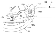
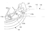
この状態で後輪側車体120を後輪20の車軸周りに後傾させていくと、転倒防止部材126の他端部である補助輪126bが接地する。さらに後輪側車体120を後輪20の車軸周りに後傾させていくと、前記第2の傾動位置で転倒防止部材126のロック部材係合部126fがクロスメンバ124aに係合し、転倒防止部材126の上方への傾動が規制される。
この時、後輪側車体120の重心位置が、車両前後方向において、後輪20の接地位置と転倒防止部材126の補助輪126bの接地位置との間に配置されるか、その近傍に配置されることが好ましい。これにより、後輪側車体120が後輪20および転倒防止部材126により安定して支持された状態となる。
一方、後輪側車体120が後傾すると、各第1の凹部121aが斜め上方に開口した状態となるので、前輪側車体110の第1のクロスメンバ113aが第1の凹部121aに安定して支持される。このため、持ち手部125cから手を離し、前輪側車体110の後端側を持ち上げて第1のクロスメンバ113aを第1の凹部121aから抜き出すことにより、前輪側車体110を後輪側車体120から取外すことができる。この時も後輪側車体120は後輪20および転倒防止部材126により安定して支持されている。このように分解された後に、前輪側車体110および後輪側車体120は自動車等に積載される。
続いて、前輪側車体110と後輪側車体120とを連結する方法の一例を説明する。
先ず、転倒防止部材126が第2の傾動位置に配置さている状態で、転倒防止部材126の補助輪126bと後輪20を接地させる。この状態で、第1の凹部121aに前輪側車体110の第1のクロスメンバ113aを入れる。これにより、前輪側車体10が第1の凹部121aと前輪110とにより支持された状態になる。
先ず、転倒防止部材126が第2の傾動位置に配置さている状態で、転倒防止部材126の補助輪126bと後輪20を接地させる。この状態で、第1の凹部121aに前輪側車体110の第1のクロスメンバ113aを入れる。これにより、前輪側車体10が第1の凹部121aと前輪110とにより支持された状態になる。
次に、後輪側車体120を後輪20の車軸周りに前方に傾動する。これにより、図10に示すように第2のクロスメンバ113bが連結ロック部材127の傾斜面127bに下方から当接する。この状態でさらに後輪側車体120を後輪20の車軸周りに前方に傾動させると、連結ロック部材127が車両前方に傾動し、これにより第2のクロスメンバ113bが第2の凹部121b内に入る。また、第2のクロスメンバ113bが第2の凹部121b内に入ると、付勢部材127dにより連結ロック部材127が車両後方に傾動し、連結ロック部材127により前輪側車体110と後輪側車体120との連結が維持される。
このように、本実施形態によれば、操作レバー130により傾動ロック部材128による傾動の規制が解除されると、転倒防止部材126が第1の傾動位置よりも上方の第2の傾動位置に傾動し、その位置でクロスメンバ124aにより上方への傾動が規制される。
このため、転倒防止部材126の補助輪126bを接地させると、後輪側車体120の重心の位置が車両後方に移動し、例えば重心の位置を後輪20の接地部と補助輪126bの接地部との間に配置し、後輪側車体120を後輪20および転倒防止部材126により安定して支持することが可能となる。
このため、転倒防止部材126の補助輪126bを接地させると、後輪側車体120の重心の位置が車両後方に移動し、例えば重心の位置を後輪20の接地部と補助輪126bの接地部との間に配置し、後輪側車体120を後輪20および転倒防止部材126により安定して支持することが可能となる。
また、本実施形態では、操作レバー130により連結ロック部材127を退避位置Bに移動させて前輪側車体110と後輪側車体120との連結のロックを解除した際に、傾動ロック部材128による傾動の規制が解除され、転倒防止部材126が第1の傾動位置よりも上方の第2の傾動位置に傾動し、その位置でクロスメンバ124aにより上方への傾動が規制される。このため、連結の解除操作を行う時に、後輪側車体120が後輪20と転倒防止部材126とにより安定して支持可能な状態になり、これは連結の解除操作を容易化する上で有利である。
また、傾動ロック部材128を傾動させると、リンク部材129により連結ロック部材127も傾動する。このため、連結の解除操作を行う時に傾動ロック部材128による傾動規制が連動して解除され、容易且つ確実に後輪側車体120を後輪20と転倒防止部材126とにより安定して支持可能な状態にすることができる。なお、操作レバー130を連結ロック部材127に固定し、連結ロック部材127を傾動させるとリンク部材129により傾動ロック部材128も傾動するように構成してもよい。
また、前輪側車体110と後輪側車体120とが連結されている時に第1の傾動位置に配置されて電動モビリティの後方への転倒を防止する転倒防止部材126を、前輪側車体110との連結が解除された後輪側車体120の支持に利用するので、後輪側車体120を支持するための専用の部材を設ける必要がない。
また、後輪側車体120に設けられた傾動可能な操作レバー130の傾動状態を確認することにより、傾動ロック部材128による傾動規制の状態や、連結ロック部材127によるロックの状態を物理的に確認することができる。このため、傾動ロック部材128による傾動規制や連結ロック部材127によるロックが解除されていない状態で後輪側車体120を後傾させる等の無理な操作が防止される。また、前輪側車体110と後輪側車体120とを連結する時も、傾動ロック部材128による傾動規制の状態および連結ロック部材127によるロックの状態を物理的に確認することができる。
また、傾動ロック部材128により上方への傾動が規制された状態で、転倒防止部材126の下方への傾動が後輪側フレーム121のクロスメンバ124aにより規制される。また、傾動ロック部材128による傾動の規制が解除され、転倒防止部材126が第2の傾動位置に傾動した際にも、同じクロスメンバ124aにより転倒防止部材126の上方への傾動が規制される。このため、転倒防止部材126の傾動を制御するための構成をシンプルにすることができ、これは重量低減に関する強い要求があり設計スペースが限られている電動モビリティにおいて有利である。
なお、本実施形態では、操作レバー130により傾動ロック部材128や連結ロック部材127を傾動させるものを示したが、例えば傾動ロック部材128および連結ロック部材127の少なくとも一方に減速機の出力軸を連結すると共に、減速機の駆動軸をモータにより駆動するように構成することも可能である。この場合、制御装置80が受付けるロック解除信号又はロック信号に基づき、制御装置80がモータ50を制御するように構成してもよい。
また、本実施形態では、座席ユニット40をモビリティ本体30から取外した後に、前輪側車体110と後輪側車体120とに分解したものを示した。これに対し、座席ユニット40を取外さずに前輪側車体110と後輪側車体120とに分解することも可能である。座席ユニット40が後輪側車体120ではなく前輪側車体110に取付けられている場合や、座席ユニット40が小さい場合は、座席ユニット40を取外す必要が無い場合もある。
また、本実施形態では、転倒防止部材126が後輪20よりも車両後方に突出し、転倒防止部材126を上方に傾動させて転倒防止部材126の他端部の補助輪126bと後輪20とにより後輪側車体120を支持するものを示した。これに対し、転倒防止部材126を補助輪126bが無いものとすることもできる。この場合でも、転倒防止部材126により電動モビリティの後方への転倒を防止することができ、転倒防止部材126の他端部と後輪20とにより後輪側車体120を支持することもできる。
また、本実施形態において、後輪側車体120の重心位置が後輪20の回転軸線20aに対し車両後方に位置している場合等は、転倒防止部材126が第1の傾動位置よりも上方に傾動しないように構成する一方、後輪側車体120よりも車両前方に突出する突出部材を設けることも可能である。
この場合、突出部材はその一端が後輪側車体120に支持されて上下方向に傾動可能である。また、前輪側車体110と後輪側車体120との連結状態において、突出部材は例えば車両前後方向に延びるように第1の傾動位置に配置されている。そして、前輪側車体110と後輪側車体120との連結を解除する時や、その後に、突出部材は第1の傾動位置よりも上方の第2の傾動位置に傾動可能となる。これにより、突出部材の他端部と後輪20とにより後輪側車体120を支持すると、連結時よりも後輪側車体120の重心位置が車両前方に移動する。
なお、後輪側フレーム121に第1の凹部121aの代わりに車両幅方向に延びるクロスメンバ、係合ピン等を設け、前輪側フレーム111の各サイドメンバ112に第1のクロスメンバ113aの代わりに例えば車両前方に向かって斜め下方に開口する略U字形状の凹部をそれぞれ設け、各凹部に後輪側フレーム121のクロスメンバ、係合ピン等が係合するように構成してもよい。
また、後輪側フレーム121の第2の凹部121bの代わりに車両幅方向に延びるクロスメンバ、係合ピン等を設け、前輪側フレーム111の各サイドメンバ112に第2のクロスメンバ113bの代わりに例えば上方に向かって開口する略U字形状の凹部をそれぞれ設け、各凹部に後輪側フレーム121のクロスメンバ、係合ピン等が係合するように構成してもよい。また、その他の方式で前輪側車体110と後輪側車体120とが取外し可能に連結されるように構成されていてもよい。
なお、本実施形態では、後輪側フレーム121にそれぞれ略U字形状の第1の凹部121aおよび第2の凹部121bを設けるものを示した。これに対し、第1の凹部121aは、前輪側車体110と後輪側車体120との連結時に第1のクロスメンバ113aに下方、上方、および車両後方から当接し、車両前方に開口するものであれば、他の形状であっても前述と同様の作用効果を奏する。また、第2の凹部121bも、前輪側車体110と後輪側車体120との連結時に第2のクロスメンバ113bに上方、車両後方、および車両前方から当接し、下方に開口するものであれば、他の形状であっても前述と同様の作用効果を奏する。
また、前述のように前輪側フレーム111に第1のクロスメンバ113aの代わりに車両前方に向かって斜め下方に開口する凹部を設ける場合も、前輪側車体110と後輪側車体120との連結時に後輪側車体120のクロスメンバ、係合ピン等に上方、下方、および車両後方から当接し、車両前方に向かって斜め下方に開口するものであれば、他の形状であっても前述と同様の作用効果を奏する。
また、前述のように前輪側フレーム111に第2のクロスメンバ113bの代わりに上方に向かって開口する凹部を設ける場合も、前輪側車体110と後輪側車体120との連結時に後輪側車体120のクロスメンバ、係合ピン等に下方、車両後方、および車両前方から当接し、上方に開口するものであれば、他の形状であっても前述と同様の作用効果を奏する。
なお、本実施形態では、傾動部材126aのロック部材係合部126fがクロスメンバ124aに係合することにより、転倒防止部材126の第2の傾動位置よりも上方への傾動が規制されるものを示した。これに対し、傾動部材126aの他端部と傾動中心126dとの間の一部が後輪側カバー120aや後輪側フレーム121と係合し、これにより転倒防止部材126の第2の傾動位置よりも上方への傾動が規制されてもよい。後輪20および転倒防止部材126により後輪側車体120を支持できるならば、さらに他の構造により転倒防止部材126の第2の傾動位置よりも上方への傾動が規制されてもよい。
10 前輪
20 後輪
30 モビリティ本体
31 ボディ
33 座席支持部
40 座席ユニット
41 座面部
42 背凭れ部
43 コントロールアーム
50 モータ
60 制御ユニット
110 前輪側車体
111 前輪側フレーム
112 サイドメンバ
113a 第1のクロスメンバ
113b 第2のクロスメンバ
120 後輪側車体
121 後輪側フレーム
121a 第1の凹部
121b 第2の凹部
122 下側部材
122a サイドメンバ
123 モータ固定部
124a,124b,124c クロスメンバ
125 支持部フレーム
125c 持ち手部
126 転倒防止部材(突出部材)
126a 傾動部材
126b 補助輪
127 連結ロック部材(第1の規制手段)
127b 傾斜面
128 傾動ロック部材
128a 係合ピン
129 リンク部材
130 操作レバー
BA バッテリ
Claims (7)
- 前輪側車体と、
該前輪側車体に取外し可能に連結された後輪側車体と、
該後輪側車体に一端側が支持されて上下方向に傾動可能であり、該後輪側車体に設けられた後輪の外周面よりも他端部が車両前方又は車両後方に突出している突出部材と、
第1の傾動位置よりも上方に傾動しないように前記突出部材の傾動規制を行う第1の規制手段と、
前記第1の傾動位置に比べ上方である第2の傾動位置よりも上方に傾動しないように前記突出部材の傾動規制を行う第2の規制手段と、
前記第1の規制手段による前記傾動規制を解除可能な操作手段と、
を備える電動モビリティ。 - 前記後輪側車体に設けられ、前記前輪側車体と前記後輪側車体との連結を維持するロック位置および該連結を解除可能な状態とする退避位置に移動可能な連結ロック部材をさらに備え、
前記操作手段を操作すると前記連結ロック部材が前記ロック位置から前記退避位置に移動するように構成されており、
前記操作手段の操作により前記連結ロック部材を前記ロック位置から前記退避位置に移動させる時に、前記第1の規制手段による前記傾動規制が解除されるように構成されている請求項1に記載の電動モビリティ。 - 前記第1の規制手段が、前記第1の傾動位置で前記突出部材に係合して前記傾動規制を行う傾動ロック部材であり、
前記連結ロック部材の前記ロック位置から前記退避位置への移動と、前記傾動ロック部材の前記突出部材に係合する位置から前記突出部材との係合が解除される位置への移動とを連動させるリンク機構をさらに備える請求項2に記載の電動モビリティ。 - 前記突出部材が、前記第1の傾動位置に配置された時に該電動モビリティの後方への転倒を防止するものである請求項1~3の何れかに記載の電動モビリティ。
- 前記操作手段が前記後輪側車体に設けられた傾動可能な操作レバーであり、
該操作レバーの傾動により前記連結ロック部材および前記傾動ロック部材の一方が操作されると共に、他方が前記リンク機構を介して操作されるように構成されている請求項3に記載の電動モビリティ。 - 前記後輪側車体を構成する所定のフレームと接触することにより、前記第1の傾動位置よりも下方又は前記第1の傾動位置よりも下方である第3の傾動位置よりも下方への前記突出部材の傾動が規制され、前記所定のフレームと接触することにより、前記第2の傾動位置よりも上方への前記突出部材の傾動が規制される請求項1~5の何れかに記載の電動モビリティ。
- 前輪側車体から後輪側車体を取外し可能な電動モビリティの分解方法であって、
前記後輪側車体が、突出部材と、第1の規制手段とを備えるものであり、前記突出部材は、前記後輪側車体に一端側が支持されて上下方向に傾動可能であり、また、前記突出部材の他端部は、前記後輪側車体に設けられた後輪の外周面よりも車両前方又は車両後方に突出しており、前記第1の規制手段は、第1の傾動位置よりも上方に傾動しないように前記突出部材の傾動規制を行うものであり、
前記第1の規制手段による前記傾動規制を解除して前記突出部材を前記第1の傾動位置よりも上方の第2の傾動位置まで傾動させるステップと、
該第2の傾動位置に配置された前記突出部材の他端部を接地させ、該他端部と前記後輪とにより前記後輪側車体を支持するステップと、
を有する電動モビリティの分解方法。
Priority Applications (2)
| Application Number | Priority Date | Filing Date | Title |
|---|---|---|---|
| CN201880001434.XA CN109070967B (zh) | 2017-03-16 | 2018-03-14 | 电动移动车和其拆解方法 |
| CN201811393523.1A CN109484544B (zh) | 2017-03-16 | 2018-03-14 | 电动移动车 |
Applications Claiming Priority (2)
| Application Number | Priority Date | Filing Date | Title |
|---|---|---|---|
| JP2017-051782 | 2017-03-16 | ||
| JP2017051782A JP6746521B2 (ja) | 2017-03-16 | 2017-03-16 | 電動モビリティおよびその分解方法 |
Publications (1)
| Publication Number | Publication Date |
|---|---|
| WO2018168911A1 true WO2018168911A1 (ja) | 2018-09-20 |
Family
ID=63523788
Family Applications (1)
| Application Number | Title | Priority Date | Filing Date |
|---|---|---|---|
| PCT/JP2018/009915 WO2018168911A1 (ja) | 2017-03-16 | 2018-03-14 | 電動モビリティおよびその分解方法 |
Country Status (3)
| Country | Link |
|---|---|
| JP (1) | JP6746521B2 (ja) |
| CN (2) | CN109070967B (ja) |
| WO (1) | WO2018168911A1 (ja) |
Cited By (2)
| Publication number | Priority date | Publication date | Assignee | Title |
|---|---|---|---|---|
| JP2021146216A (ja) * | 2020-03-17 | 2021-09-27 | 緯創資通股▲ふん▼有限公司Wistron Corporation | 歩行器 |
| US11273716B2 (en) * | 2019-03-12 | 2022-03-15 | Kubota Corporation | Electric work vehicle |
Families Citing this family (5)
| Publication number | Priority date | Publication date | Assignee | Title |
|---|---|---|---|---|
| WO2021132198A1 (ja) * | 2019-12-27 | 2021-07-01 | Whill株式会社 | 電動モビリティ |
| CN111249076B (zh) * | 2020-01-21 | 2022-04-12 | 广州视源电子科技股份有限公司 | 轮椅 |
| CN111249079B (zh) * | 2020-01-21 | 2021-12-07 | 广州视源电子科技股份有限公司 | 防倾轮椅 |
| JP2021123116A (ja) * | 2020-01-31 | 2021-08-30 | 本田技研工業株式会社 | 電動車両及び移動体 |
| JP7068359B2 (ja) * | 2020-01-31 | 2022-05-16 | 本田技研工業株式会社 | 移動体および電動車両 |
Citations (6)
| Publication number | Priority date | Publication date | Assignee | Title |
|---|---|---|---|---|
| JPH07300087A (ja) * | 1994-05-06 | 1995-11-14 | Kubota Corp | 小型電動カート |
| JPH08308882A (ja) * | 1995-05-19 | 1996-11-26 | Atex Co Ltd | 介助兼用電動車椅子のステップ装置 |
| JP2001029398A (ja) * | 1999-07-23 | 2001-02-06 | Araco Corp | 小型電動車両 |
| JP2004135811A (ja) * | 2002-10-17 | 2004-05-13 | Atex Co Ltd | 電動車椅子 |
| JP2007062669A (ja) * | 2005-09-01 | 2007-03-15 | Suzuki Motor Corp | 小型電動車両の転倒防止装置 |
| JP3135395U (ja) * | 2007-07-03 | 2007-09-13 | 自遊實股▲分▼有限公司 | 人載せキャリヤー用折畳み装置 |
Family Cites Families (14)
| Publication number | Priority date | Publication date | Assignee | Title |
|---|---|---|---|---|
| FR2675688A1 (fr) * | 1991-04-26 | 1992-10-30 | Poirier Ets | Vehicule individuel utilisable en version manuelle ou motorisee, notamment fauteuil roulant ou tricycle. |
| JP2610738B2 (ja) * | 1991-12-24 | 1997-05-14 | 株式会社クボタ | 小型電動車 |
| US5351774A (en) * | 1992-06-02 | 1994-10-04 | Quickie Designs Inc. | Powered wheelchair with a detachable power drive assembly |
| EP0912154B1 (en) * | 1996-07-17 | 2004-10-20 | Deka Products Limited Partnership | Anti-tipping mechanism |
| EP1441401A1 (en) * | 2003-01-25 | 2004-07-28 | Pihsiang Machinery MFG. Co., Ltd. | Battery module structure of electrical vehicle |
| TWM270935U (en) * | 2004-10-26 | 2005-07-21 | Yung-Cheng Chen | Detachable structure of scooter frame |
| JP4783624B2 (ja) * | 2005-12-13 | 2011-09-28 | 株式会社カワムラサイクル | 車いす |
| JP5045707B2 (ja) * | 2009-05-28 | 2012-10-10 | トヨタ自動車株式会社 | 走行装置、その制御方法、及び制御プログラム |
| CN201814751U (zh) * | 2010-10-11 | 2011-05-04 | 长沙恒润机械有限责任公司 | 一种既可站立又可平躺的电动轮椅 |
| CN202173534U (zh) * | 2011-07-06 | 2012-03-28 | 苏州康帝医疗器械有限公司 | 轻便型电动轮椅 |
| US20130149032A1 (en) * | 2011-12-09 | 2013-06-13 | Sunpex Technology Co., Ltd. | Fixing member for vehicle frame joint of scooter |
| JP6309297B2 (ja) * | 2014-02-18 | 2018-04-11 | Whill株式会社 | 電動モビリティおよびその制御方法 |
| CN106572937B (zh) * | 2014-06-23 | 2019-07-23 | 韩国生产技术研究院 | 具有另外的安装框架的行驶辅助装置 |
| CN104224462A (zh) * | 2014-08-22 | 2014-12-24 | 太仓市中峰模具塑胶有限公司 | 一种多功能电动轮椅 |
-
2017
- 2017-03-16 JP JP2017051782A patent/JP6746521B2/ja active Active
-
2018
- 2018-03-14 CN CN201880001434.XA patent/CN109070967B/zh active Active
- 2018-03-14 WO PCT/JP2018/009915 patent/WO2018168911A1/ja active Application Filing
- 2018-03-14 CN CN201811393523.1A patent/CN109484544B/zh active Active
Patent Citations (6)
| Publication number | Priority date | Publication date | Assignee | Title |
|---|---|---|---|---|
| JPH07300087A (ja) * | 1994-05-06 | 1995-11-14 | Kubota Corp | 小型電動カート |
| JPH08308882A (ja) * | 1995-05-19 | 1996-11-26 | Atex Co Ltd | 介助兼用電動車椅子のステップ装置 |
| JP2001029398A (ja) * | 1999-07-23 | 2001-02-06 | Araco Corp | 小型電動車両 |
| JP2004135811A (ja) * | 2002-10-17 | 2004-05-13 | Atex Co Ltd | 電動車椅子 |
| JP2007062669A (ja) * | 2005-09-01 | 2007-03-15 | Suzuki Motor Corp | 小型電動車両の転倒防止装置 |
| JP3135395U (ja) * | 2007-07-03 | 2007-09-13 | 自遊實股▲分▼有限公司 | 人載せキャリヤー用折畳み装置 |
Cited By (2)
| Publication number | Priority date | Publication date | Assignee | Title |
|---|---|---|---|---|
| US11273716B2 (en) * | 2019-03-12 | 2022-03-15 | Kubota Corporation | Electric work vehicle |
| JP2021146216A (ja) * | 2020-03-17 | 2021-09-27 | 緯創資通股▲ふん▼有限公司Wistron Corporation | 歩行器 |
Also Published As
| Publication number | Publication date |
|---|---|
| CN109070967B (zh) | 2021-01-29 |
| JP6746521B2 (ja) | 2020-08-26 |
| CN109484544A (zh) | 2019-03-19 |
| CN109070967A (zh) | 2018-12-21 |
| CN109484544B (zh) | 2023-02-28 |
| JP2018154201A (ja) | 2018-10-04 |
Similar Documents
| Publication | Publication Date | Title |
|---|---|---|
| WO2018168911A1 (ja) | 電動モビリティおよびその分解方法 | |
| EP3251930B1 (en) | Electric-powered vehicle | |
| JP3451426B2 (ja) | 車椅子の組付構造 | |
| WO2018169034A1 (ja) | コネクタ構造 | |
| WO2019106926A1 (ja) | 電動車椅子 | |
| JP2015070897A (ja) | 移乗支援装置及び連結機構 | |
| WO2018168914A1 (ja) | 電動モビリティおよびその分解方法 | |
| JP6795541B2 (ja) | 電動三輪車両 | |
| JP2018154202A5 (ja) | ||
| JP6980948B2 (ja) | 電動モビリティ | |
| WO2017104193A1 (ja) | 複輪車両 | |
| JP6791903B2 (ja) | 電動車両 | |
| JP2002337780A (ja) | 鞍乗型車両における折り畳み式車体構造 | |
| JP2018149009A (ja) | 電動モビリティおよびバッテリの装着方法 | |
| JP5825973B2 (ja) | 歩行型作業機及びその支持装置 | |
| CN114514169B (zh) | 电动移动设备 | |
| JP7399993B2 (ja) | 自転車用両脚スタンドおよび自転車 | |
| JP7370298B2 (ja) | スタンドおよびこれを備えた自転車 | |
| JP7033751B2 (ja) | キックスケーター | |
| JP2007176442A (ja) | 左右二輪車 | |
| JP2004182003A (ja) | 懸架装置 | |
| JP2014043219A (ja) | 作業車両の安全フレーム | |
| JPH08301120A (ja) | 多輪公転式移動装置 | |
| JP2008006943A (ja) | 産業車両 | |
| JP2005178412A (ja) | 乗用田植機 |
Legal Events
| Date | Code | Title | Description |
|---|---|---|---|
| 121 | Ep: the epo has been informed by wipo that ep was designated in this application |
Ref document number: 18768508 Country of ref document: EP Kind code of ref document: A1 |
|
| NENP | Non-entry into the national phase |
Ref country code: DE |
|
| 122 | Ep: pct application non-entry in european phase |
Ref document number: 18768508 Country of ref document: EP Kind code of ref document: A1 |