WO2018155162A1 - シールド板付き電子部品及び電子部品用シールド板 - Google Patents
シールド板付き電子部品及び電子部品用シールド板 Download PDFInfo
- Publication number
- WO2018155162A1 WO2018155162A1 PCT/JP2018/003964 JP2018003964W WO2018155162A1 WO 2018155162 A1 WO2018155162 A1 WO 2018155162A1 JP 2018003964 W JP2018003964 W JP 2018003964W WO 2018155162 A1 WO2018155162 A1 WO 2018155162A1
- Authority
- WO
- WIPO (PCT)
- Prior art keywords
- electronic component
- shield plate
- main surface
- metal film
- shield
- Prior art date
Links
Images


Classifications
-
- B—PERFORMING OPERATIONS; TRANSPORTING
- B32—LAYERED PRODUCTS
- B32B—LAYERED PRODUCTS, i.e. PRODUCTS BUILT-UP OF STRATA OF FLAT OR NON-FLAT, e.g. CELLULAR OR HONEYCOMB, FORM
- B32B38/00—Ancillary operations in connection with laminating processes
- B32B38/04—Punching, slitting or perforating
-
- H—ELECTRICITY
- H01—ELECTRIC ELEMENTS
- H01L—SEMICONDUCTOR DEVICES NOT COVERED BY CLASS H10
- H01L23/00—Details of semiconductor or other solid state devices
- H01L23/12—Mountings, e.g. non-detachable insulating substrates
- H01L23/14—Mountings, e.g. non-detachable insulating substrates characterised by the material or its electrical properties
- H01L23/15—Ceramic or glass substrates
-
- B—PERFORMING OPERATIONS; TRANSPORTING
- B32—LAYERED PRODUCTS
- B32B—LAYERED PRODUCTS, i.e. PRODUCTS BUILT-UP OF STRATA OF FLAT OR NON-FLAT, e.g. CELLULAR OR HONEYCOMB, FORM
- B32B9/00—Layered products comprising a layer of a particular substance not covered by groups B32B11/00 - B32B29/00
- B32B9/005—Layered products comprising a layer of a particular substance not covered by groups B32B11/00 - B32B29/00 comprising one layer of ceramic material, e.g. porcelain, ceramic tile
-
- B—PERFORMING OPERATIONS; TRANSPORTING
- B32—LAYERED PRODUCTS
- B32B—LAYERED PRODUCTS, i.e. PRODUCTS BUILT-UP OF STRATA OF FLAT OR NON-FLAT, e.g. CELLULAR OR HONEYCOMB, FORM
- B32B9/00—Layered products comprising a layer of a particular substance not covered by groups B32B11/00 - B32B29/00
- B32B9/04—Layered products comprising a layer of a particular substance not covered by groups B32B11/00 - B32B29/00 comprising such particular substance as the main or only constituent of a layer, which is next to another layer of the same or of a different material
- B32B9/045—Layered products comprising a layer of a particular substance not covered by groups B32B11/00 - B32B29/00 comprising such particular substance as the main or only constituent of a layer, which is next to another layer of the same or of a different material of synthetic resin
-
- H—ELECTRICITY
- H01—ELECTRIC ELEMENTS
- H01L—SEMICONDUCTOR DEVICES NOT COVERED BY CLASS H10
- H01L23/00—Details of semiconductor or other solid state devices
- H01L23/02—Containers; Seals
- H01L23/06—Containers; Seals characterised by the material of the container or its electrical properties
-
- H—ELECTRICITY
- H01—ELECTRIC ELEMENTS
- H01L—SEMICONDUCTOR DEVICES NOT COVERED BY CLASS H10
- H01L23/00—Details of semiconductor or other solid state devices
- H01L23/28—Encapsulations, e.g. encapsulating layers, coatings, e.g. for protection
- H01L23/29—Encapsulations, e.g. encapsulating layers, coatings, e.g. for protection characterised by the material, e.g. carbon
-
- H—ELECTRICITY
- H01—ELECTRIC ELEMENTS
- H01L—SEMICONDUCTOR DEVICES NOT COVERED BY CLASS H10
- H01L23/00—Details of semiconductor or other solid state devices
- H01L23/28—Encapsulations, e.g. encapsulating layers, coatings, e.g. for protection
- H01L23/31—Encapsulations, e.g. encapsulating layers, coatings, e.g. for protection characterised by the arrangement or shape
- H01L23/3107—Encapsulations, e.g. encapsulating layers, coatings, e.g. for protection characterised by the arrangement or shape the device being completely enclosed
- H01L23/3121—Encapsulations, e.g. encapsulating layers, coatings, e.g. for protection characterised by the arrangement or shape the device being completely enclosed a substrate forming part of the encapsulation
-
- H—ELECTRICITY
- H01—ELECTRIC ELEMENTS
- H01L—SEMICONDUCTOR DEVICES NOT COVERED BY CLASS H10
- H01L23/00—Details of semiconductor or other solid state devices
- H01L23/552—Protection against radiation, e.g. light or electromagnetic waves
-
- H—ELECTRICITY
- H01—ELECTRIC ELEMENTS
- H01L—SEMICONDUCTOR DEVICES NOT COVERED BY CLASS H10
- H01L24/00—Arrangements for connecting or disconnecting semiconductor or solid-state bodies; Methods or apparatus related thereto
- H01L24/01—Means for bonding being attached to, or being formed on, the surface to be connected, e.g. chip-to-package, die-attach, "first-level" interconnects; Manufacturing methods related thereto
- H01L24/42—Wire connectors; Manufacturing methods related thereto
- H01L24/47—Structure, shape, material or disposition of the wire connectors after the connecting process
- H01L24/48—Structure, shape, material or disposition of the wire connectors after the connecting process of an individual wire connector
-
- H—ELECTRICITY
- H01—ELECTRIC ELEMENTS
- H01L—SEMICONDUCTOR DEVICES NOT COVERED BY CLASS H10
- H01L24/00—Arrangements for connecting or disconnecting semiconductor or solid-state bodies; Methods or apparatus related thereto
- H01L24/80—Methods for connecting semiconductor or other solid state bodies using means for bonding being attached to, or being formed on, the surface to be connected
- H01L24/83—Methods for connecting semiconductor or other solid state bodies using means for bonding being attached to, or being formed on, the surface to be connected using a layer connector
-
- H—ELECTRICITY
- H01—ELECTRIC ELEMENTS
- H01L—SEMICONDUCTOR DEVICES NOT COVERED BY CLASS H10
- H01L25/00—Assemblies consisting of a plurality of individual semiconductor or other solid state devices ; Multistep manufacturing processes thereof
- H01L25/16—Assemblies consisting of a plurality of individual semiconductor or other solid state devices ; Multistep manufacturing processes thereof the devices being of types provided for in two or more different main groups of groups H01L27/00 - H01L33/00, or in a single subclass of H10K, H10N, e.g. forming hybrid circuits
- H01L25/165—Containers
-
- H—ELECTRICITY
- H05—ELECTRIC TECHNIQUES NOT OTHERWISE PROVIDED FOR
- H05K—PRINTED CIRCUITS; CASINGS OR CONSTRUCTIONAL DETAILS OF ELECTRIC APPARATUS; MANUFACTURE OF ASSEMBLAGES OF ELECTRICAL COMPONENTS
- H05K1/00—Printed circuits
- H05K1/02—Details
- H05K1/0213—Electrical arrangements not otherwise provided for
- H05K1/0216—Reduction of cross-talk, noise or electromagnetic interference
- H05K1/023—Reduction of cross-talk, noise or electromagnetic interference using auxiliary mounted passive components or auxiliary substances
- H05K1/0233—Filters, inductors or a magnetic substance
-
- H—ELECTRICITY
- H05—ELECTRIC TECHNIQUES NOT OTHERWISE PROVIDED FOR
- H05K—PRINTED CIRCUITS; CASINGS OR CONSTRUCTIONAL DETAILS OF ELECTRIC APPARATUS; MANUFACTURE OF ASSEMBLAGES OF ELECTRICAL COMPONENTS
- H05K1/00—Printed circuits
- H05K1/02—Details
- H05K1/03—Use of materials for the substrate
- H05K1/0306—Inorganic insulating substrates, e.g. ceramic, glass
-
- H—ELECTRICITY
- H05—ELECTRIC TECHNIQUES NOT OTHERWISE PROVIDED FOR
- H05K—PRINTED CIRCUITS; CASINGS OR CONSTRUCTIONAL DETAILS OF ELECTRIC APPARATUS; MANUFACTURE OF ASSEMBLAGES OF ELECTRICAL COMPONENTS
- H05K3/00—Apparatus or processes for manufacturing printed circuits
- H05K3/22—Secondary treatment of printed circuits
- H05K3/28—Applying non-metallic protective coatings
- H05K3/284—Applying non-metallic protective coatings for encapsulating mounted components
-
- H—ELECTRICITY
- H05—ELECTRIC TECHNIQUES NOT OTHERWISE PROVIDED FOR
- H05K—PRINTED CIRCUITS; CASINGS OR CONSTRUCTIONAL DETAILS OF ELECTRIC APPARATUS; MANUFACTURE OF ASSEMBLAGES OF ELECTRICAL COMPONENTS
- H05K9/00—Screening of apparatus or components against electric or magnetic fields
- H05K9/0007—Casings
- H05K9/002—Casings with localised screening
- H05K9/0022—Casings with localised screening of components mounted on printed circuit boards [PCB]
- H05K9/0024—Shield cases mounted on a PCB, e.g. cans or caps or conformal shields
- H05K9/0032—Shield cases mounted on a PCB, e.g. cans or caps or conformal shields having multiple parts, e.g. frames mating with lids
-
- H—ELECTRICITY
- H05—ELECTRIC TECHNIQUES NOT OTHERWISE PROVIDED FOR
- H05K—PRINTED CIRCUITS; CASINGS OR CONSTRUCTIONAL DETAILS OF ELECTRIC APPARATUS; MANUFACTURE OF ASSEMBLAGES OF ELECTRICAL COMPONENTS
- H05K9/00—Screening of apparatus or components against electric or magnetic fields
- H05K9/0007—Casings
- H05K9/002—Casings with localised screening
- H05K9/0039—Galvanic coupling of ground layer on printed circuit board [PCB] to conductive casing
-
- H—ELECTRICITY
- H05—ELECTRIC TECHNIQUES NOT OTHERWISE PROVIDED FOR
- H05K—PRINTED CIRCUITS; CASINGS OR CONSTRUCTIONAL DETAILS OF ELECTRIC APPARATUS; MANUFACTURE OF ASSEMBLAGES OF ELECTRICAL COMPONENTS
- H05K9/00—Screening of apparatus or components against electric or magnetic fields
- H05K9/0073—Shielding materials
- H05K9/0075—Magnetic shielding materials
-
- B—PERFORMING OPERATIONS; TRANSPORTING
- B32—LAYERED PRODUCTS
- B32B—LAYERED PRODUCTS, i.e. PRODUCTS BUILT-UP OF STRATA OF FLAT OR NON-FLAT, e.g. CELLULAR OR HONEYCOMB, FORM
- B32B38/00—Ancillary operations in connection with laminating processes
- B32B38/04—Punching, slitting or perforating
- B32B2038/045—Slitting
-
- B—PERFORMING OPERATIONS; TRANSPORTING
- B32—LAYERED PRODUCTS
- B32B—LAYERED PRODUCTS, i.e. PRODUCTS BUILT-UP OF STRATA OF FLAT OR NON-FLAT, e.g. CELLULAR OR HONEYCOMB, FORM
- B32B2307/00—Properties of the layers or laminate
- B32B2307/20—Properties of the layers or laminate having particular electrical or magnetic properties, e.g. piezoelectric
- B32B2307/212—Electromagnetic interference shielding
-
- H—ELECTRICITY
- H01—ELECTRIC ELEMENTS
- H01L—SEMICONDUCTOR DEVICES NOT COVERED BY CLASS H10
- H01L2224/00—Indexing scheme for arrangements for connecting or disconnecting semiconductor or solid-state bodies and methods related thereto as covered by H01L24/00
- H01L2224/01—Means for bonding being attached to, or being formed on, the surface to be connected, e.g. chip-to-package, die-attach, "first-level" interconnects; Manufacturing methods related thereto
- H01L2224/10—Bump connectors; Manufacturing methods related thereto
- H01L2224/15—Structure, shape, material or disposition of the bump connectors after the connecting process
- H01L2224/16—Structure, shape, material or disposition of the bump connectors after the connecting process of an individual bump connector
- H01L2224/161—Disposition
- H01L2224/16151—Disposition the bump connector connecting between a semiconductor or solid-state body and an item not being a semiconductor or solid-state body, e.g. chip-to-substrate, chip-to-passive
- H01L2224/16221—Disposition the bump connector connecting between a semiconductor or solid-state body and an item not being a semiconductor or solid-state body, e.g. chip-to-substrate, chip-to-passive the body and the item being stacked
- H01L2224/16225—Disposition the bump connector connecting between a semiconductor or solid-state body and an item not being a semiconductor or solid-state body, e.g. chip-to-substrate, chip-to-passive the body and the item being stacked the item being non-metallic, e.g. insulating substrate with or without metallisation
- H01L2224/16235—Disposition the bump connector connecting between a semiconductor or solid-state body and an item not being a semiconductor or solid-state body, e.g. chip-to-substrate, chip-to-passive the body and the item being stacked the item being non-metallic, e.g. insulating substrate with or without metallisation the bump connector connecting to a via metallisation of the item
-
- H—ELECTRICITY
- H01—ELECTRIC ELEMENTS
- H01L—SEMICONDUCTOR DEVICES NOT COVERED BY CLASS H10
- H01L2224/00—Indexing scheme for arrangements for connecting or disconnecting semiconductor or solid-state bodies and methods related thereto as covered by H01L24/00
- H01L2224/01—Means for bonding being attached to, or being formed on, the surface to be connected, e.g. chip-to-package, die-attach, "first-level" interconnects; Manufacturing methods related thereto
- H01L2224/10—Bump connectors; Manufacturing methods related thereto
- H01L2224/15—Structure, shape, material or disposition of the bump connectors after the connecting process
- H01L2224/16—Structure, shape, material or disposition of the bump connectors after the connecting process of an individual bump connector
- H01L2224/161—Disposition
- H01L2224/16151—Disposition the bump connector connecting between a semiconductor or solid-state body and an item not being a semiconductor or solid-state body, e.g. chip-to-substrate, chip-to-passive
- H01L2224/16221—Disposition the bump connector connecting between a semiconductor or solid-state body and an item not being a semiconductor or solid-state body, e.g. chip-to-substrate, chip-to-passive the body and the item being stacked
- H01L2224/16225—Disposition the bump connector connecting between a semiconductor or solid-state body and an item not being a semiconductor or solid-state body, e.g. chip-to-substrate, chip-to-passive the body and the item being stacked the item being non-metallic, e.g. insulating substrate with or without metallisation
- H01L2224/16238—Disposition the bump connector connecting between a semiconductor or solid-state body and an item not being a semiconductor or solid-state body, e.g. chip-to-substrate, chip-to-passive the body and the item being stacked the item being non-metallic, e.g. insulating substrate with or without metallisation the bump connector connecting to a bonding area protruding from the surface of the item
-
- H—ELECTRICITY
- H01—ELECTRIC ELEMENTS
- H01L—SEMICONDUCTOR DEVICES NOT COVERED BY CLASS H10
- H01L2224/00—Indexing scheme for arrangements for connecting or disconnecting semiconductor or solid-state bodies and methods related thereto as covered by H01L24/00
- H01L2224/01—Means for bonding being attached to, or being formed on, the surface to be connected, e.g. chip-to-package, die-attach, "first-level" interconnects; Manufacturing methods related thereto
- H01L2224/42—Wire connectors; Manufacturing methods related thereto
- H01L2224/47—Structure, shape, material or disposition of the wire connectors after the connecting process
- H01L2224/48—Structure, shape, material or disposition of the wire connectors after the connecting process of an individual wire connector
- H01L2224/481—Disposition
- H01L2224/48151—Connecting between a semiconductor or solid-state body and an item not being a semiconductor or solid-state body, e.g. chip-to-substrate, chip-to-passive
- H01L2224/48221—Connecting between a semiconductor or solid-state body and an item not being a semiconductor or solid-state body, e.g. chip-to-substrate, chip-to-passive the body and the item being stacked
- H01L2224/48245—Connecting between a semiconductor or solid-state body and an item not being a semiconductor or solid-state body, e.g. chip-to-substrate, chip-to-passive the body and the item being stacked the item being metallic
- H01L2224/48247—Connecting between a semiconductor or solid-state body and an item not being a semiconductor or solid-state body, e.g. chip-to-substrate, chip-to-passive the body and the item being stacked the item being metallic connecting the wire to a bond pad of the item
-
- H—ELECTRICITY
- H01—ELECTRIC ELEMENTS
- H01L—SEMICONDUCTOR DEVICES NOT COVERED BY CLASS H10
- H01L23/00—Details of semiconductor or other solid state devices
- H01L23/52—Arrangements for conducting electric current within the device in operation from one component to another, i.e. interconnections, e.g. wires, lead frames
- H01L23/538—Arrangements for conducting electric current within the device in operation from one component to another, i.e. interconnections, e.g. wires, lead frames the interconnection structure between a plurality of semiconductor chips being formed on, or in, insulating substrates
- H01L23/5383—Multilayer substrates
-
- H—ELECTRICITY
- H01—ELECTRIC ELEMENTS
- H01L—SEMICONDUCTOR DEVICES NOT COVERED BY CLASS H10
- H01L23/00—Details of semiconductor or other solid state devices
- H01L23/58—Structural electrical arrangements for semiconductor devices not otherwise provided for, e.g. in combination with batteries
- H01L23/64—Impedance arrangements
- H01L23/645—Inductive arrangements
-
- H—ELECTRICITY
- H01—ELECTRIC ELEMENTS
- H01L—SEMICONDUCTOR DEVICES NOT COVERED BY CLASS H10
- H01L24/00—Arrangements for connecting or disconnecting semiconductor or solid-state bodies; Methods or apparatus related thereto
- H01L24/01—Means for bonding being attached to, or being formed on, the surface to be connected, e.g. chip-to-package, die-attach, "first-level" interconnects; Manufacturing methods related thereto
- H01L24/10—Bump connectors ; Manufacturing methods related thereto
- H01L24/15—Structure, shape, material or disposition of the bump connectors after the connecting process
- H01L24/16—Structure, shape, material or disposition of the bump connectors after the connecting process of an individual bump connector
-
- H—ELECTRICITY
- H01—ELECTRIC ELEMENTS
- H01L—SEMICONDUCTOR DEVICES NOT COVERED BY CLASS H10
- H01L2924/00—Indexing scheme for arrangements or methods for connecting or disconnecting semiconductor or solid-state bodies as covered by H01L24/00
- H01L2924/19—Details of hybrid assemblies other than the semiconductor or other solid state devices to be connected
- H01L2924/191—Disposition
- H01L2924/19101—Disposition of discrete passive components
- H01L2924/19105—Disposition of discrete passive components in a side-by-side arrangement on a common die mounting substrate
-
- H—ELECTRICITY
- H05—ELECTRIC TECHNIQUES NOT OTHERWISE PROVIDED FOR
- H05K—PRINTED CIRCUITS; CASINGS OR CONSTRUCTIONAL DETAILS OF ELECTRIC APPARATUS; MANUFACTURE OF ASSEMBLAGES OF ELECTRICAL COMPONENTS
- H05K1/00—Printed circuits
- H05K1/02—Details
- H05K1/14—Structural association of two or more printed circuits
- H05K1/141—One or more single auxiliary printed circuits mounted on a main printed circuit, e.g. modules, adapters
-
- H—ELECTRICITY
- H05—ELECTRIC TECHNIQUES NOT OTHERWISE PROVIDED FOR
- H05K—PRINTED CIRCUITS; CASINGS OR CONSTRUCTIONAL DETAILS OF ELECTRIC APPARATUS; MANUFACTURE OF ASSEMBLAGES OF ELECTRICAL COMPONENTS
- H05K2201/00—Indexing scheme relating to printed circuits covered by H05K1/00
- H05K2201/07—Electric details
- H05K2201/0707—Shielding
- H05K2201/0715—Shielding provided by an outer layer of PCB
-
- H—ELECTRICITY
- H05—ELECTRIC TECHNIQUES NOT OTHERWISE PROVIDED FOR
- H05K—PRINTED CIRCUITS; CASINGS OR CONSTRUCTIONAL DETAILS OF ELECTRIC APPARATUS; MANUFACTURE OF ASSEMBLAGES OF ELECTRICAL COMPONENTS
- H05K2201/00—Indexing scheme relating to printed circuits covered by H05K1/00
- H05K2201/10—Details of components or other objects attached to or integrated in a printed circuit board
- H05K2201/10227—Other objects, e.g. metallic pieces
- H05K2201/10371—Shields or metal cases
Definitions
- the present invention relates to an electronic component having a shield plate and a shield plate used for the electronic component.
- the shield plate described in Patent Document 1 a metal plate obtained by processing a metal thin film into a predetermined shape is used. Further, the shield plate described in Patent Document 2 uses a metal mesh supported by a resin film.
- an object of the present invention is to provide a shield plate and an electronic component including the same that can efficiently shield noises of various frequencies.
- the electronic component with a shield plate includes a wiring board, a surface-mounted component mounted on the surface of the wiring board, and a shield plate attached to the top side of the surface-mounted component.
- the shield plate includes a magnetic ceramic sintered plate having a first main surface and a second main surface, and a first metal film provided on the first main surface of the magnetic ceramic sintered plate.
- the magnetic ceramic sintered plate acts as a magnetic shield layer
- the first metal film acts as a metal shield layer.
- the magnetic ceramic sintered plate has a higher magnetic permeability than a composite material in which a magnetic filler is dispersed in a resin layer.
- the magnetic shield layer can shield low frequency noise mainly efficiently.
- the metal shield layer can mainly shield high frequency noise.
- the second main surface of the magnetic ceramic sintered plate is provided with a plurality of cuts.
- the flexibility can be enhanced by the plurality of cuts in the second main surface of the magnetic ceramic sintered plate.
- Magnetic ceramic sintered plates are less flexible than composite materials and mesh materials. However, flexibility is improved by having a cut.
- the first main surface of the magnetic ceramic sintered plate is provided with the first metal film, even if the magnetic ceramic sintered plate is cracked, the first metal film is not divided. That is, since the first metal film functions as a support material for the magnetic ceramic sintered plate and the shape of the shield plate is maintained, it does not affect the shielding of low frequency noise.
- the first metal film of the electronic component with a shield plate of the present invention is preferably a metal thin film.
- the first metal film is a metal thin film
- the entire thickness of the shield plate does not increase.
- the metal thin film has high adhesion to the ceramic sintered plate.
- the electronic component with a shield plate of the present invention preferably includes a first metal film on the first main surface of the magnetic ceramic sintered plate and a second metal film on the second main surface.
- the second metal film of the electronic component with a shield plate of the present invention is preferably a metal thin film.
- the second metal film is a metal thin film
- the entire thickness of the shield plate does not increase.
- the metal thin film has high adhesion to the ceramic sintered plate.
- the first main surface of the magnetic ceramic sintered plate is opposed to the surface-mounted component.
- the first metal film since the first metal film is provided on the first main surface side, the first metal film can be easily connected to the ground of the electronic component. Thereby, high frequency noise can be efficiently guided to the ground, and the shielding performance is improved.
- the electronic component with a shield plate of the present invention preferably has a conductor for connecting the surface electrode of the wiring board and the first metal film.
- the high frequency noise propagated to the first metal film can be efficiently guided to the surface electrode of the wiring board, and the shielding performance is improved.
- a sealing resin is provided on the surface of the wiring electrode.
- the shield plate is preferably attached to the top surface side of the sealing resin.
- the shield plate can be easily attached to a desired position.
- the electronic component with a shield plate of the present invention includes a via electrode that penetrates through the magnetic ceramic sintered plate and has one end exposed at the first main surface and the other end exposed at the second main surface. Is preferred.
- the first metal film can be easily connected to the ground of the electronic component by the via electrode penetrating the magnetic ceramic sintered plate. Thereby, the high frequency noise can be efficiently guided to the ground, and the shielding property is improved.
- the electronic component with a shield plate of the present invention includes a wiring board, a surface-mounted component mounted on the surface of the wiring board, and a shield plate attached to the top surface side of the surface-mounted component.
- a plurality of cuts are formed on one main surface of the shield plate.
- a metal film is provided only on one main surface where a plurality of cuts are formed.
- the shield plate for electronic parts includes a magnetic ceramic sintered plate having a first main surface and a second main surface, and a metal film on at least one of the first main surface and the second main surface of the ceramic sintered plate. I have.
- both low-frequency noise and high-frequency noise can be shielded by simply placing a shield plate on the surface side (top surface side) of the electronic component.
- the surface-mounted component in the electronic component with a shield plate of the present invention includes a first surface-mounted component and a second surface-mounted component mounted so as to be adjacent to the wiring board.
- the first surface mount component and the second surface mount component are covered with a sealing resin.
- the sealing resin has a gap. In addition, this gap constitutes a thin portion that is thinner than the thickness of the region where the first surface mount component and the second surface mount component are disposed.
- the space of the surface mount component is preferably opened on the top or bottom surface of the sealing resin.
- the thin part in the electronic component with a shield plate according to the present invention is formed between the first surface mount component and the second surface mount component in plan view from the one main surface of the first metal film to the one main surface of the wiring board. ing.
- the surface-mounted component in the electronic component with a shield plate of the present invention includes a first surface-mounted component and a second surface-mounted component that are mounted adjacent to each other on the wiring board.
- a plurality of cuts are formed between the first surface mount component and the second surface mount component when the one main surface of the wiring board is viewed in plan from the one main surface of the first metal film.
- interruption comprises the thin part thinner than the thickness of the area
- a thin portion can be easily formed by a plurality of cuts. Further, stress can be concentrated on the thin portion.
- an inductor conductor is provided on the top surface side of the first surface mount component.
- the surface mount component generates a first magnetic flux
- the inductor conductor on the top surface side generates a second magnetic flux.
- the inductor conductor on the top surface side is formed on the first surface mount component at a position where at least a part of the opening overlaps the first surface mount component when the one main surface of the wiring board is viewed in plan from the one main surface of the first metal film. It is arranged to face each other.
- the winding direction of the inductor conductor on the top surface side is set to a direction in which the second magnetic flux generated from the inductor conductor on the top surface side and the first magnetic flux generated from the first surface mount component are weakened.
- the first magnetic flux generated from the first surface mount component to the top surface side can be weakened by the second magnetic flux generated from the inductor conductor, and the characteristics of the electronic component with the shield plate can be improved.
- noises of various frequencies can be efficiently shielded.
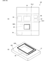
- (A) is the external appearance perspective view from the 1st main surface side in the shield plate for electronic components which concerns on the 1st Embodiment of this invention
- (B) is an external appearance perspective view from the 2nd main surface side. is there.
- (A) is side sectional drawing which shows the structure of the electronic component with a shield board which concerns on the 1st Embodiment of this invention
- (B) is the figure which expanded a part of shield board.
- (A) is side surface sectional drawing which shows the structure of the electronic component with a shield board which concerns on the 4th Embodiment of this invention
- (B) is the figure which expanded a part of shield board.
- (A) is side surface sectional drawing which shows the structure of the electronic component with a shield board which concerns on the 5th Embodiment of this invention
- (B) is the figure which expanded a part of shield board. It is a partial exploded perspective view which shows the structure of the electronic component with a shield board which concerns on the 6th Embodiment of this invention.
- (A) is side surface sectional drawing which shows the structure of the electronic component with a shield board which concerns on the 6th Embodiment of this invention.
- (B) is the elements on larger scale of the side sectional view showing the composition of the electronic component with a shield board concerning the 6th embodiment of the present invention. It is side surface sectional drawing which shows the structure of the electronic component with a shield board which concerns on the 7th Embodiment of this invention. It is side surface sectional drawing which shows the structure of the electronic component with a shield board which concerns on the 8th Embodiment of this invention. It is side surface sectional drawing which shows the structure of the electronic component with a shield board which concerns on the 9th Embodiment of this invention. It is side surface sectional drawing which shows the structure of the electronic component with a shield board which concerns on the 10th Embodiment of this invention.
- (A) is the front schematic diagram from the 1st main surface side of the electronic component with a shield board concerning the 16th embodiment of the present invention
- (B) is the perspective view which expanded the portion where the coil is arranged. It is. It is a figure which shows the outline
- FIG. 1A is an external perspective view from the first main surface side of the electronic component shield plate according to the first embodiment of the present invention.
- FIG. 1B is an external perspective view from the second main surface side of the electronic component shield plate according to the first embodiment of the present invention.
- FIG. 2A is a side cross-sectional view showing the configuration of the electronic component with a shield plate according to the first embodiment of the present invention.
- FIG. 2B is an enlarged view of a part of the shield plate in FIG. In FIG. 1 (A) and FIG. 1 (B), in order to make the drawings easy to see, some of the reference numerals are omitted.
- the electronic component shield plate 10 includes a metal film 11 and a magnetic ceramic sintered plate 12.
- the metal film 11 corresponds to the “first metal film” of the present invention.
- the metal film 11 is formed on the first main surface 101 of the magnetic ceramic sintered plate 12.
- a plurality of cut lines SL are formed on the second main surface 102 of the magnetic ceramic sintered plate 12.
- the electronic component 1 with a shield plate includes a shield plate 10 for electronic components, a printed wiring board 20, a sealing resin 40, and surface mount electronic components 51 and 52.
- the electronic component shield plate 10 is mounted on the surface side of the surface-mounted electronic components 51 and 52 and the printed wiring board 20 via the adhesive layer 15.
- the printed wiring board 20 has a rectangular shape in plan view, that is, a rectangular parallelepiped shape.
- the printed wiring board 20 includes a first main surface 201 and a second main surface 202 that face each other, and further has side surfaces that connect the first main surface 201 and the second main surface 202.
- the printed wiring board 20 is a glass epoxy board such as FR4.
- the ground terminal conductors 33 and 34 and the external connection terminal conductor 35 are formed on the second main surface 202 of the printed wiring board 20.
- the component mounting land conductors 41 and 42 are formed on the first main surface 201 of the printed wiring board 20.
- the component mounting land conductors 41 and 42 are connected to the ground terminal conductors 33 and 34 and the external connection terminal conductor 35 by connection conductors 31 and 32 in a predetermined circuit pattern.
- the surface mount electronic component 51 is mounted on the component mounting land conductor 41, and the surface mount electronic component 52 is mounted on the component mounting land conductor.
- the sealing resin 40 is formed on the first main surface 201 side of the printed wiring board 20.
- the sealing resin 40 covers the first main surface 201 of the printed wiring board 20 and the surface mount electronic components 51 and 52.
- the shield plate 10 for electronic parts is mounted on the surface of the sealing resin 40 opposite to the surface that contacts the printed wiring board 20. That is, the electronic component shield plate 10 is arranged on the top surface side of the printed wiring board 20. The electronic component shield plate 10 is disposed on the top surface side of the sealing resin 40. The electronic component shield plate 10 is attached to the sealing resin 40 such that the second main surface 102 faces the sealing resin 40. The electronic component shield plate 10 is attached to the sealing resin 40 via the adhesive layer 15.
- the adhesive layer 15 may be conductive or insulating.
- the electronic component shield plate 10 includes the metal film 11 and the magnetic ceramic sintered plate 12.
- the metal film 11 is preferably a metal thin film.
- the thickness of the metal thin film is preferably 25 ⁇ m to 50 ⁇ m. For this reason, the thickness of the shield plate 10 for electronic components does not increase.
- a metal shield layer having a dense arrangement of metal particles can be obtained.
- the metal film 11 is formed on the sintered magnetic ceramic sintered plate 12 by sputtering or the like.
- the metal film 11 may be a printed film of a conductive paste. In this case, you may bake what printed the electrically conductive paste on the sintered magnetic ceramic sintered plate 12. Alternatively, a conductive paste may be printed on the magnetic ceramic sintered plate 12 before firing, and the magnetic ceramic sintered plate 12 and the conductive paste may be fired simultaneously. By using these forming methods, the adhesion between the metal film 11 and the magnetic ceramic sintered plate 12 is high.
- the magnetic ceramic sintered plate 12 acts as a magnetic shield layer
- the metal film 11 acts as a metal shield layer.
- the magnetic ceramic sintered plate 12 forming the magnetic shield layer has a higher magnetic permeability than a composite material in which a magnetic filler is dispersed in a resin layer. Thereby, the magnetic shield layer can shield low frequency noise mainly efficiently.
- the metal film 11 is preferably made of Ni, Si, Cu, permalloy or the like. Thereby, mainly high frequency noise can be effectively shielded.
- the low frequency is less than 100 MHz
- the high frequency is higher than 100 MHz.
- a plurality of slits SL are formed in the magnetic ceramic sintered plate 12.
- the cut SL is formed from the second main surface 102 of the magnetic ceramic sintered plate 12 toward the first main surface 101.
- the slits SL are formed in a lattice shape when the second main surface 102 of the magnetic ceramic sintered plate 12 is viewed in plan. As shown in FIG. 2B, the gap d is about 2 mm, for example.
- the magnetic ceramic sintered plate 12 is a sintered plate, it is inferior in flexibility as compared with a composite material or a mesh material. However, the flexibility is improved by forming a plurality of cut lines SL. In addition, one or more cuts SL may be formed, but the flexibility is further improved by forming a plurality of cuts SL. As described above, the cut SL is not intended to divide the shield plate 10 for electronic parts, but improves flexibility. Therefore, the cut SL may not be V-shaped but may be thinner than other parts. Further, the cut SL need not be formed by a straight line continuous from one end to the other end of the magnetic ceramic sintered plate 12. For example, the cut SL may be formed by disposing a plurality of concave portions intermittently in a straight line.
- the metal film 11 is formed on the first main surface 101 of the magnetic ceramic sintered plate 12, even if the magnetic ceramic sintered plate 12 is cracked from the cut SL during bending or the like, The metal film 11 functions as a support material for the magnetic ceramic sintered plate 12. As a result, the shape of the electronic component shield plate 10 is maintained, and the gap through the cut SL cannot be formed in the magnetic ceramic sintered plate 12, so that there is no effect on the shielding of low-frequency noise.
- the electronic component shield plate 10 and the shielded electronic component 1 that can shield low-frequency noise and high-frequency noise.
- the electronic component shield plate 10 is deformed according to the shape of the place to be mounted, is in close contact with this place, and is easy to attach.
- FIG. 3 is a side sectional view showing the configuration of the electronic component with a shield plate according to the second embodiment of the present invention.
- the electronic component 1A with a shield plate according to the second embodiment is different from the electronic component 1 with a shield plate according to the first embodiment in that the electronic component shield plate 10A, the via-hole conductor 62A, 64A differs in the shape of the terminal conductor 63A.
- the electronic component shield plate 10A includes a metal film 11A and a magnetic ceramic sintered plate 12A.
- Other configurations of the electronic component with shield plate 1A are the same as those of the electronic component with shield plate 1, and the description of the same parts is omitted.
- the metal film 11A corresponds to the metal film 11 of the first embodiment of the present invention
- the magnetic ceramic sintered plate 12A corresponds to the magnetic ceramic sintered plate 12 of the first embodiment of the present invention.
- the electronic component shield plate 10A is mounted on the surface of the sealing resin 40 opposite to the surface in contact with the printed wiring board 20A.
- the electronic component shield plate 10 ⁇ / b> A is disposed on the top surface side of the sealing resin 40.
- the electronic component shield plate 10 ⁇ / b> A is attached to the sealing resin 40 so that the first main surface 101 ⁇ / b> A faces the sealing resin 40.
- the electronic component shield plate 10A having an inverted shape of the electronic component shield plate 10 of FIG. 2 is mounted on the connection conductor 61A on the surface of the sealing resin 40 via the adhesive layer 15A.
- the adhesive layer 15A has conductivity.
- the electronic component shield plate 10A includes a metal film 11A and a magnetic ceramic sintered plate 12A.
- the metal film 11A corresponds to the “first metal film” of the present invention.
- the metal film 11A is formed on the first main surface 101A of the magnetic ceramic sintered plate 12A.
- a plurality of cut lines SL are formed in the second main surface 102A of the magnetic ceramic sintered plate 12A.
- connection conductor 61A is formed on the surface of the sealing resin 40.
- the terminal conductor 63A is formed on the surface where the printed wiring board 20A contacts the sealing resin 40.
- the via-hole conductor 62A penetrates the sealing resin 40, and one end thereof is exposed on the surface on which the electronic component shield plate 10A is mounted, and is connected to the connection conductor 61A. The other end is exposed on the surface on which the printed wiring board 20A is mounted and is connected to the terminal conductor 63A.
- the via-hole conductor 64A penetrates the printed wiring board 20A, one end is exposed to the first main surface 201A of the printed wiring board 20A, and is connected to the terminal conductor 63A. The other end is exposed on the second main surface 202A of the printed wiring board 20A and is connected to the ground terminal conductor 33.
- the magnetic ceramic sintered plate 12A acts as a magnetic shield layer, and can mainly shield low-frequency noise efficiently.
- the metal film 11A functions as a metal shield layer, and can mainly shield high-frequency noise efficiently.
- the high-frequency noise propagated to the electronic component shield plate 10A is efficiently guided to the ground of the shielded electronic component 1A through the connection conductor 61A, the via-hole conductor 62A, the terminal conductor 63A, and the via-hole conductor 64A. Therefore, the shielding property of high frequency noise is improved.
- connection conductor 61A can be omitted, but by providing the connection conductor 61A, high-frequency noise can be more efficiently guided to the ground.
- the metal film 11A can be easily connected to the ground of the electronic component 1A with a shield plate.
- FIG. 4 is a side sectional view showing a configuration of an electronic component with a shield plate according to a third embodiment of the present invention.
- the shielded electronic component 1B according to the third embodiment is different from the shielded electronic component 1 according to the first embodiment in that the electronic component shield plate 10B, magnetic ceramic ceramic
- the shapes of the connecting plate 12B, the metal post 62B, the terminal conductor 63B, and the via hole conductor 64B are different.
- the other configuration of the electronic component 1B with the shield plate is the same as that of the electronic component 1 with the shield plate, and the description of the same parts is omitted.
- the metal film 11B corresponds to the metal film 11 of the first embodiment of the present invention
- the magnetic ceramic sintered plate 12B corresponds to the magnetic ceramic sintered plate 12 of the first embodiment of the present invention.
- the electronic component shield plate 10B is mounted on the surface of the sealing resin 40 opposite to the surface in contact with the printed wiring board 20B.
- the electronic component shield plate 10 ⁇ / b> B is disposed on the top surface side of the sealing resin 40.
- the electronic component shield plate 10 ⁇ / b> B is attached to the sealing resin 40 such that the first main surface 101 ⁇ / b> B faces the sealing resin 40.
- the electronic component shield plate 10B having an inverted shape of the electronic component shield plate 10 of FIG. 2 is mounted on the sealing resin 40 via the adhesive layer 15A.
- the electronic component shield plate 10B includes a metal film 11B, a magnetic ceramic sintered plate 12B, and a metal film 13B.
- the metal film 11B corresponds to the “first metal film” of the present invention.
- the metal film 11B is formed on the first main surface 101B of the magnetic ceramic sintered plate 12B.
- the metal film 13B corresponds to the “second metal film” of the present invention.
- the metal film 13B is formed on the second main surface 102B of the magnetic ceramic sintered plate 12B.
- the metal films 11B and 13B are formed by sputtering or the like. Further, a plurality of cut lines SL are formed on the second main surface 102B of the magnetic ceramic sintered plate 12B.
- the terminal conductor 63B is formed on the surface where the printed wiring board 20B contacts the sealing resin 40.
- the metal post 62B is formed from the surface that penetrates the sealing resin 40 and contacts the first main surface 201B of the printed wiring board 20B toward the surface on which the electronic component shield plate 10B is mounted. One end of the metal post 62B protrudes from the surface of the sealing resin 40, and the other end is connected to the terminal conductor 63B.
- the metal post 62B is a conductor.
- the via-hole conductor 64B penetrates the printed wiring board 20B, one end is exposed on the first main surface 201B of the printed wiring board 20B, and is connected to the terminal conductor 63B. The other end is exposed on the second main surface 202B of the printed wiring board 20B. Further, the metal film 11B is in contact with the metal post 62B.
- the magnetic ceramic sintered plate 12B acts as a magnetic shield layer, and can mainly shield low-frequency noise efficiently.
- the metal films 11B and 13B function as a metal shield layer. Since both surfaces of the first main surface 101B and the second main surface 102B of the magnetic ceramic sintered plate 12B act as metal shield layers, mainly high-frequency noise can be shielded more efficiently.
- the high-frequency noise passes through the metal post 62B, the terminal conductor 63B, and the via-hole conductor 64B, and is efficiently guided to the ground of the electronic component 1B with the shield plate.
- FIG. 5A is a side sectional view showing a configuration of an electronic component with a shield plate according to the fourth embodiment of the present invention.
- FIG. 5B is an enlarged view of a part of the shield plate in FIG. In FIG. 5A, in order to make the drawing easier to see, some of the reference numerals are omitted.
- the electronic component with a shield plate 1C according to the fourth embodiment is different from the electronic component 1 with a shield plate according to the first embodiment.
- the shield plate 10C, the magnetic ceramic sintered plate 12C, the connection conductor 61C, the via-hole conductors 62C and 64C, and the terminal conductor 63C are different in shape.
- Other configurations of the electronic component with shield plate 1 ⁇ / b> C are the same as those of the electronic component with shield plate 1, and the description of similar parts is omitted.
- the metal film 11C corresponds to the metal film 11 of the first embodiment of the present invention
- the magnetic ceramic sintered plate 12C corresponds to the magnetic ceramic sintered plate 12 of the first embodiment of the present invention.
- the electronic component shield plate 10C is mounted on the surface of the sealing resin 40 opposite to the surface in contact with the printed wiring board 20C.
- the electronic component shield plate 10 ⁇ / b> C is disposed on the top surface side of the sealing resin 40.
- the electronic component shield plate 10 ⁇ / b> C is attached to the sealing resin 40 such that the first main surface 101 ⁇ / b> C faces the sealing resin 40.
- the electronic component shield plate 10C having an inverted shape of the electronic component shield plate 10 of FIG. 2 is mounted via the connection conductor 61C and the adhesive layer 15C.
- the electronic component shield plate 10C includes a metal film 11C, a magnetic ceramic sintered plate 12C, a metal film 13C, and a via conductor 16C.
- the metal film 11C corresponds to the “first metal film” of the present invention.
- the metal film 11C is formed on the first main surface 101C of the magnetic ceramic sintered plate 12C.
- the metal film 13C corresponds to the “second metal film” of the present invention.
- the metal film 13C is formed on the second main surface 102C of the magnetic ceramic sintered plate 12C.
- the metal films 11C and 13C are formed on the second main surface 102C of the electronic component shield plate 10C by sputtering or the like.
- a plurality of cuts SL are formed in the second main surface 102C of the magnetic ceramic sintered plate 12C.
- a plurality of via conductors 16C are formed on the magnetic ceramic sintered plate 12C.
- the via conductor 16C is preferably formed between the cuts SL.
- the via conductor 16C penetrates the magnetic ceramic sintered plate 12C, and one end is exposed to the first main surface 101C of the magnetic ceramic sintered plate 12C and is connected to the metal film 11C. The other end is exposed on the second main surface 102C of the magnetic ceramic sintered plate 12C and connected to the metal film 13C.
- the connection conductor 61C is formed on the surface of the sealing resin 40.
- the terminal conductor 63C is formed on the surface where the printed wiring board 20C contacts the sealing resin 40.
- the via-hole conductor 62C penetrates the sealing resin 40, and one end of the via-hole conductor 62C is exposed on the surface on which the electronic component shield plate 10C is mounted and connected to the connection conductor 61C. The other end is exposed on the surface on which the printed wiring board 20C is mounted and is connected to the terminal conductor 63C.
- the via-hole conductor 64C penetrates the printed wiring board 20C, and one end thereof is exposed to the first main surface 201C of the printed wiring board 20C and is connected to the terminal conductor 63C. The other end is exposed on the second main surface 202C of the printed wiring board 20C and connected to the ground terminal conductor 33.
- the magnetic ceramic sintered plate 12C acts as a magnetic shield layer, and can mainly shield low-frequency noise efficiently.
- the metal films 11C and 13C function as a metal shield layer. Since both surfaces of the first main surface 101C and the second main surface 102C of the magnetic ceramic sintered plate 12C act as metal shield layers, mainly high-frequency noise can be shielded more efficiently.
- the via conductor 16C the metal film 11C can be electrically connected to the metal film 13C and the connection conductor 61C, and the high frequency propagated to the metal film 11C can be guided to the ground of the electronic component 1C with a shield plate.
- FIG. 6A is a side sectional view showing a configuration of an electronic component with a shield plate according to the fifth embodiment of the present invention.
- FIG. 6B is an enlarged view of a part of the shield plate in FIG.
- the electronic component with shield plate 1D according to the fifth embodiment is different from the electronic component with shield plate according to the first embodiment.
- the shield plate 10D, the solder 14D, the via-hole conductors 62D and 64D, and the terminal conductor 63D are different in shape.
- Other configurations of the electronic component 1D with the shield plate are the same as those of the electronic component 1 with the shield plate, and the description of the same parts is omitted.
- the metal film 11D corresponds to the metal film 11 of the first embodiment of the present invention
- the magnetic ceramic sintered plate 12D corresponds to the magnetic ceramic sintered plate 12 of the first embodiment of the present invention.
- the electronic component shield plate 10D is mounted on the surface of the sealing resin 40 opposite to the surface in contact with the printed wiring board 20D.
- the electronic component shield plate 10 ⁇ / b> D is disposed on the top surface side of the sealing resin 40.
- the electronic component shield plate 10 ⁇ / b> D is attached to the sealing resin 40 such that the first main surface 101 ⁇ / b> D faces the sealing resin 40.
- an electronic component shield plate 10D having a shape obtained by inverting the electronic component shield plate 10 of FIG. 2 is mounted via the adhesive layer 15D.
- the electronic component shield plate 10D includes a metal film 11D, a magnetic ceramic sintered plate 12D, and a metal film 13D.
- the metal film 11D corresponds to the “first metal film” of the present invention.
- the metal film 11D is formed on the first main surface 101D of the magnetic ceramic sintered plate 12D.
- the metal film 13D corresponds to the “second metal film” of the present invention.
- the metal film 11D is formed on the first main surface 101D of the electronic component shield plate 10D, and the metal film 13D is formed on the second main surface 102D of the electronic component shield plate 10D by sputtering or the like.
- a plurality of cut lines SL are formed on the second main surface 102D of the magnetic ceramic sintered plate 12D.
- the magnetic ceramic sintered plate 12D has a side surface that connects the first main surface 101D and the second main surface 102D. Similarly, the metal films 11D and 13D reach the side surface of the magnetic ceramic sintered plate 12D.
- the solder 14D is disposed along the side surface of the magnetic ceramic sintered plate 12D and connects the metal films 11D and 13D.
- the via-hole conductor 62D penetrates the sealing resin 40, one end is exposed on the surface on which the electronic component shield plate 10D is mounted, and the other end is exposed on the surface on which the printed wiring board 20D is mounted. It is connected to the conductor 63D.
- the via-hole conductor 64D penetrates the printed wiring board 20D, one end is exposed at the first main surface 201D of the printed wiring board 20D, is connected to the terminal conductor 63D, and the other end is the second main wiring board 20D.
- the surface 202D is exposed and connected to the ground terminal conductor 33.
- the magnetic ceramic sintered plate 12D acts as a magnetic shield layer, and can mainly shield low-frequency noise efficiently.
- the metal films 11D and 13D function as a metal shield layer. Since both surfaces of the first main surface 101D and the second main surface 102D of the magnetic ceramic sintered plate 12D act as a metal shield layer, mainly high-frequency noise can be shielded more efficiently. Furthermore, the high-frequency noise propagated to the metal film 13D passes through the solder 14D, the via hole conductor 62D, the terminal conductor 63D, and the via hole conductor 64D, and is efficiently guided to the ground of the electronic component 1D with the shield plate.
- the example in which the metal shield layers of the metal films 11D and 13D are formed on the magnetic ceramic sintered plate 12D is shown. Even when the metal film 13D is formed only on the second main surface 102D, the above-described effects can be obtained.
- FIG. 7 is a partially exploded perspective view showing a configuration of an electronic component 1E with a shield plate according to a sixth embodiment of the present invention.
- FIG. 8A is a view showing an AA cross section of FIG. 7 according to the sixth embodiment of the present invention.
- FIG. 8B is a partially enlarged view of FIG.
- an electronic component with shield plate 1E includes a shield plate 10E for electronic components, surface-mounted electronic components 51 and 52, a printed wiring board 70, and a metal frame 71.
- the electronic component shield plate 10E includes a metal film 11E and a magnetic ceramic sintered plate 12E.
- the metal film 11E corresponds to the “first metal film” of the present invention.
- the metal film 11E is formed on the first main surface 101E of the magnetic ceramic sintered plate 12D.
- a plurality of slits SL are formed in the second main surface 102E of the magnetic ceramic sintered plate 12E.
- the printed wiring board 70 has a rectangular shape in plan view, that is, a rectangular parallelepiped shape.
- the printed wiring board 70 includes a first main surface 701 and a second main surface 702 that face each other, and further has side surfaces that connect the first main surface 701 and the second main surface 702.
- the printed wiring board 70 is a glass epoxy board such as FR4.
- the component mounting land conductors 43 and 44 are formed on the first main surface 701 of the printed wiring board 70.
- the surface mounting electronic component 51 is mounted on the component mounting land conductor 43, and the surface mounting electronic component 52 is mounted on the component mounting land conductor 44.
- the shape of the metal frame 71 is a rectangular frame, and the metal frame 71 is mounted on the first main surface 701 of the printed wiring board 70.
- the metal frame 71 is made of a metal having high conductivity.
- the metal frame 71 is arranged so as to surround the mounting area of the surface-mounted electronic components 51 and 52.
- the electronic component shield plate 10E is mounted on the surface of the metal frame 71 opposite to the surface in contact with the first main surface 701.
- the electronic component shield plate 10E is attached to the metal frame 71 via the adhesive layer 15E so that the second main surface 102E faces the first main surface 701 of the printed wiring board 70.
- the surface mount electronic components 51 and 52 are surrounded by the electronic component shield plate 10 ⁇ / b> E, the printed wiring board 70, and the metal frame 71.
- the adhesive layer 15E preferably has conductivity, and preferably has a frame shape that is the same shape as the metal frame 71. Further, for example, the adhesive layer 15E may be a conductive bonding material such as solder.
- the electronic component shield plate 10E includes the metal film 11E and the magnetic ceramic sintered plate 12E.
- the metal film 11E is preferably a metal thin film.
- the thickness of the metal thin film is preferably 25 ⁇ m to 50 ⁇ m. For this reason, the thickness of the electronic component shield plate 10E on which the metal film 11E is mounted does not increase.
- a metal shield layer having a dense arrangement of metal particles can be obtained.
- the metal film 11E is formed by sputtering or the like on the sintered magnetic ceramic sintered plate 12E.
- the metal film 11E may be a printed film of conductive paste. In this case, you may bake what printed the electrically conductive paste on the sintered magnetic ceramic sintered plate 12E. Alternatively, a conductive paste may be printed on the magnetic ceramic sintered plate 12E before firing, and the magnetic ceramic sintered plate 12E and the conductive paste may be fired simultaneously. By using these forming methods, the metal film 11E has high adhesion to the magnetic ceramic sintered plate 12E.
- the magnetic ceramic sintered plate 12E acts as a magnetic shield layer
- the metal film 11E acts as a metal shield layer.
- the magnetic ceramic sintered plate 12E forming the magnetic shield layer has a higher magnetic permeability than a composite material in which a magnetic filler is dispersed in a resin layer. Thereby, the magnetic shield layer can shield low frequency noise mainly efficiently.
- the metal film 11 is preferably made of Ni, Si, Cu, permalloy or the like. Thereby, mainly high frequency noise can be effectively shielded.
- a plurality of slits SL are formed in the magnetic ceramic sintered plate 12E.
- the gap d shown in FIG. 8B is about 2 mm, for example.
- the cut SL is formed from the second main surface 102E of the magnetic ceramic sintered plate 12E toward the first main surface 101E.
- the slits SL are formed in a lattice shape when the second main surface 102E of the magnetic ceramic sintered plate 12E is viewed in plan. Since the magnetic ceramic sintered plate 12E is a sintered plate, it is inferior in flexibility as compared with a composite material or a mesh material. However, the flexibility is improved by forming a plurality of cut lines SL. In addition, one or more cuts SL may be formed, but the flexibility is further improved by forming a plurality of cuts SL.
- a via conductor 16E is formed on the magnetic ceramic sintered plate 12E.
- the via conductor 16E only needs to be formed at a position where it can be connected to the metal frame 71 between the cuts SL.
- the via conductor 16E penetrates the magnetic ceramic sintered plate 12E, and one end is exposed to the first main surface 101E of the magnetic ceramic sintered plate 12E and is connected to the metal film 11E. The other end is exposed to the second main surface 102E of the magnetic ceramic sintered plate 12E and is electrically connected to the metal frame 71 through the adhesive layer 15E.
- the magnetic ceramic sintered plate 12E acts as a magnetic shield layer, and can mainly shield low-frequency noise efficiently.
- the metal film 11E functions as a metal shield layer. Since the first main surface 101E of the magnetic ceramic sintered plate 12E functions as a metal shield layer, mainly high-frequency noise can be effectively shielded. Further, the high frequency noise is guided to the ground of the printed wiring board 70 (not shown) along the via conductor 16E, the adhesive layer 15E, and the metal frame 71.
- a plurality of cuts SL are formed in the magnetic ceramic sintered plate 12E, and the flexibility can be improved. Since the metal film 11E is formed on the first main surface 101E of the magnetic ceramic sintered plate 12E, even if the magnetic ceramic sintered plate 12E is cracked from the cut SL during bending or the like, the metal film 11E functions as a support material for the magnetic ceramic sintered plate 12E. As a result, the shape of the electronic component shield plate 10E is maintained, and the gap through the cut SL cannot be formed in the magnetic ceramic sintered plate 12E.
- FIG. 9 is a side sectional view showing the configuration of the electronic component with a shield plate according to the seventh embodiment of the present invention.
- the electronic component 1F with a shield plate according to the seventh embodiment differs from the electronic component 1E with a shield plate according to the sixth embodiment in the shape of the shield plate 10F for electronic components.
- Other configurations of the electronic component with shield plate 1F are the same as those of the electronic component with shield plate 1E, and the description of the same parts is omitted.
- the metal film 11F corresponds to the metal film 11E of the sixth embodiment of the present invention
- the magnetic ceramic sintered plate 12F corresponds to the magnetic ceramic sintered plate 12E of the sixth embodiment of the present invention.
- the shield plate 10F for electronic parts is mounted on the surface opposite to the surface that contacts the first main surface 701 of the metal frame 71.
- the electronic component shield plate 10F is attached to the metal frame 71 via the adhesive layer 15F so that the first main surface 101F faces the first main surface 701 of the printed wiring board 70.
- the electronic component shield plate 10F having a shape obtained by inverting the electronic component shield plate 10E of FIG. 8 is mounted on the metal frame 71 via the adhesive layer 15F.
- the adhesive layer 15 ⁇ / b> F preferably has conductivity, and preferably has a frame shape that is the same shape as the metal frame 71.
- the adhesive layer 15F may be a conductive bonding material such as solder.
- the magnetic ceramic sintered plate 12E acts as a magnetic shield layer
- the metal film 11F acts as a metal shield layer.
- the flexibility can be enhanced by the plurality of cut lines SL of the magnetic ceramic sintered plate 12F. That is, the same effect as that of the sixth embodiment of the present invention can be obtained.
- FIG. 10 is a side sectional view showing a configuration of an electronic component with a shield plate according to an eighth embodiment of the present invention.
- the electronic component with shield plate 1G according to the eighth embodiment differs from the electronic component with shield plate 1E according to the sixth embodiment in the shape of the shield plate for electronic components 10G.
- Other configurations of the electronic component with shield plate 1G are the same as those of the electronic component with shield plate 1E, and the description of the same parts is omitted.
- the magnetic ceramic sintered plate 12G corresponds to the magnetic ceramic sintered plate 12E of the sixth embodiment of the present invention.
- the metal film 11G is formed on the first main surface 101G of the magnetic ceramic sintered plate 12G. Furthermore, the metal film 11G has a shape that extends to the side surface of the magnetic ceramic sintered plate 12G and the end surface of the second main surface 102G.
- the electronic component shield plate 10G is mounted on the surface of the metal frame 71 opposite to the surface in contact with the first main surface 701.
- the electronic component shield plate 10G is attached to the metal frame 71 via the adhesive layer 15G so that the second main surface 102G faces the first main surface 701 of the printed wiring board 70.
- a portion of the metal film 11G that extends to the second main surface 102G is in contact with the adhesive layer 15G.
- the adhesive layer 15 ⁇ / b> G preferably has conductivity, and preferably has a frame shape that is the same shape as the metal frame 71. Further, for example, the adhesive layer 15G may be a conductive bonding material such as solder.
- the magnetic ceramic sintered plate 12G acts as a magnetic shield layer
- the metal film 11G acts as a metal shield layer.
- the flexibility can be enhanced by the plurality of cut lines SL of the magnetic ceramic sintered plate 12G. That is, the same effect as that of Embodiment 6 of the present invention can be obtained.
- FIG. 11 is a side sectional view showing a configuration of an electronic component with a shield plate according to a ninth embodiment of the present invention.
- the electronic component with shield plate 1H according to the ninth embodiment is different from the electronic component with shield plate 1E according to the sixth embodiment in the shape of the shield plate 10H for electronic components, and the solder 14H. It differs in that it has.
- Other configurations of the electronic component with shield plate 1H are the same as those of the electronic component with shield plate 1E, and the description of the same parts is omitted.
- the metal film 11H corresponds to the metal film 11E of the sixth embodiment of the present invention
- the magnetic ceramic sintered plate 12H corresponds to the magnetic ceramic sintered plate 12E of the sixth embodiment of the present invention.
- the electronic component shield plate 10H is obtained by omitting the via conductor 16E of the electronic component shield plate 10E and adding a metal film 17H.
- the metal film 17H is formed only on the end portion of the second main surface 102H.
- the electronic component shield plate 10G is mounted on the surface of the metal frame 71 opposite to the surface in contact with the first main surface 701.
- the electronic component shield plate 10 ⁇ / b> H is disposed such that the second main surface 102 ⁇ / b> H faces the first main surface 701 of the printed wiring board 70.
- the electronic component shield plate 10H is attached to the metal frame 71 via the adhesive layer 15H, and the metal film 17H is connected to the metal frame 71 via the adhesive layer 15H.
- the metal film 11H and the metal film 17H are electrically connected by solder 14H spreading on the side surface of the magnetic ceramic sintered plate 12H.
- the adhesive layer 15H preferably has conductivity, and preferably has a frame shape that is the same shape as the metal frame 71. Further, for example, the adhesive layer 15H may be a conductive bonding material such as solder.
- the magnetic ceramic sintered plate 12H acts as a magnetic shield layer
- the metal film 11H acts as a metal shield layer.
- the flexibility can be enhanced by the plurality of cut lines SL of the magnetic ceramic sintered plate 12H. That is, the same effect as that of Embodiment 6 of the present invention can be obtained.
- FIG. 12 is a side sectional view showing a configuration of an electronic component with a shield plate according to a tenth embodiment of the present invention.
- the electronic component 1J with a shield plate according to the tenth embodiment is provided with a gap 81 in the sealing resin 40J with respect to the electronic component 1 with a shield plate according to the first embodiment, Furthermore, it is different in that the LTCC substrate 21 is provided.
- Other configurations of the electronic component 1J with the shield plate are the same as those of the electronic component 1 with the shield plate, and the description of the same parts is omitted.
- FIG. 12 in order to make the configuration easy to see, some symbols are omitted and the dimensional relationship is changed as appropriate.
- the printed wiring board 20 in the first embodiment is replaced with an LTCC board 21 and described.
- the shape and circuit pattern of the LTCC substrate 21 are the same as those of the printed wiring substrate 20 in the first embodiment.
- the LTCC substrate 21 is mounted on the printed wiring board 90 via the connection conductor 36.
- a gap 81 is formed in the sealing resin 40J.
- the gap 81 has an opening 810 on the side (top surface side) of the sealing resin 40J that contacts the electronic component shield plate 10, and is formed between the surface mount electronic component 51 and the surface mount electronic component 52. Yes.
- the thickness of the sealing resin 40J is d42
- the thickness of the LTCC substrate 21 is d20.
- the total thickness (d20 + d42) of the thickness d42 and the thickness d20 is the total thickness of the present invention.
- the thickness of the sealing resin in the portion where the void 81 is formed is d41.
- d41 is smaller than d42. Accordingly, the portion where the gap 81 is formed and the thickness (d20 + d41) of the thickness d20 and the thickness d41 is the thin portion of the present invention.
- the gap 81 is formed between the surface-mounted electronic component 51 and the surface-mounted electronic component 52, stress on the surface-mounted electronic components 51 and 52 is relieved, and disconnection and the like are suppressed. Therefore, the performance of the electronic component 1J with a shield plate can be maintained.
- the magnetic ceramic sintered plate 12 functions as a magnetic shield layer
- the metal film 11 functions as a metal shield layer. Further, the flexibility can be enhanced by the plurality of cut lines SL of the magnetic ceramic sintered plate 12. That is, the same effect as that of the first embodiment of the present invention can be obtained.
- the effect of suppressing cracks can be obtained by relaxing the stress due to the formation of the air gap 81 while maintaining the performance of the electronic component 1J with the shield plate. Moreover, it is preferable that the space
- the thickness d41 only needs to be smaller than the thickness d42.
- FIG. 13 is a side sectional view showing a configuration of an electronic component with a shield plate according to an eleventh embodiment of the present invention.
- the electronic component 1K with a shield plate according to the eleventh embodiment is provided with a gap 82 in the sealing resin 40K with respect to the electronic component 1 with a shield plate according to the first embodiment.
- the difference is that the LTCC substrate 21 is provided.
- Other configurations of the electronic component 1K with the shield plate are the same as those of the electronic component 1 with the shield plate, and the description of the same parts is omitted.
- FIG. 13 in order to make the configuration easy to see, some symbols are omitted and the dimensional relationship is appropriately changed.
- the printed wiring board 20 in the first embodiment is replaced with an LTCC board 21 and described.
- the shape and circuit pattern of the LTCC substrate 21 are the same as those of the printed wiring substrate 20 in the first embodiment.
- the LTCC substrate 21 is mounted on the printed wiring board 90 via the connection conductor 36.
- a gap 82 is formed in the sealing resin 40K.
- the air gap 82 has an opening 820 on the side (lower surface side) in contact with the LTCC substrate 21, that is, the first main surface 201, and is formed between the surface mount electronic component 51 and the surface mount electronic component 52.
- the thickness of the sealing resin 40K is d42
- the thickness of the printed wiring board 20 is d20.
- the total thickness (d20 + d42) of the thickness d42 and the thickness d20 is the total thickness of the present invention.
- the thickness of the sealing resin in the portion where the gap 82 is formed is d43.
- d43 is smaller than d42. Therefore, the portion where the gap 82 is formed and the thickness (d20 + d43) of the thickness d20 and the thickness d43 is the thin portion of the present invention.
- the air gap 82 is formed between the surface-mounted electronic component 51 and the surface-mounted electronic component 52, stress on the surface-mounted electronic components 51 and 52 is relieved, and disconnection or the like is suppressed. As a result, the performance of the shielded electronic component 1K can be maintained.
- the magnetic ceramic sintered plate 12 acts as a magnetic shield layer
- the metal film 11 acts as a metal shield layer.
- the flexibility can be enhanced by the plurality of cut lines SL of the magnetic ceramic sintered plate 12. That is, the same effect as that of the first embodiment of the present invention can be obtained.
- the effect of suppressing cracks can be obtained by relaxing the stress due to the formation of the air gap 82 while maintaining the performance of the electronic component 1K with the shield plate. Moreover, it is preferable that the space
- the thickness d43 only needs to be smaller than the thickness d42.
- FIG. 14 is an external perspective view from the second main surface side in the electronic component shield plate according to the twelfth embodiment of the present invention.
- the electronic component shielding plate 10M according to the twelfth embodiment has a shape in which the intervals between the plurality of cut lines SL are wider than the electronic component shielding plate 10 according to the first embodiment. It differs in point.
- Other configurations of the electronic component shielding plate 10M are the same as those of the electronic component 1 with a shielding plate, and the description of the same parts is omitted.
- FIG. 14 in order to make the configuration easy to see, some symbols are omitted, and the dimensional relationship is appropriately changed.
- the slit SL1 is formed in a lattice shape when the second main surface 102 of the magnetic ceramic sintered plate 12 is viewed in plan. As shown in FIG. 14, the interval of the cut SL1 is set to d1.
- the gap d1 of the cut SL1 is formed wider than the gap d of the cut SL in the first embodiment.
- the flexibility is improved by forming a plurality of cuts SL1 as compared to an electronic component in which no cuts are created. Furthermore, the effect that the intensity
- FIG. 15 is an external appearance perspective view from the 2nd main surface 102 side in the shield plate for electronic components which concerns on the 13th Embodiment of this invention.
- the electronic component shield plate 10N according to the thirteenth embodiment is different from the electronic component shield plate 10 according to the first embodiment in the shape of the intervals between the plurality of cut lines SL.
- Other configurations of the electronic component shield plate 10N are the same as those of the electronic component shield plate 10, and the description of similar portions is omitted.
- FIG. 15 in order to make the configuration easy to see, some symbols are omitted and the dimensional relationship is appropriately changed.
- the placement position of the parts is set on the second main surface 102 of the shield plate 10N for electronic parts.
- component positions 110 and 111 are set.
- the surface mount electronic component 51 (not shown) is arranged at a position overlapping the component position 110 in a plan view, and the surface mount electronic component 52 (not shown) is arranged at a position overlapping the component position 111 in a plan view.
- the surface mount electronic component 51 is the first surface mount component of the present invention
- the surface mount electronic component 52 is the second surface mount component of the present invention.
- the magnetic ceramic sintered plate 12 is formed with a plurality of cuts SL2 avoiding the parts positions 110 and 111.
- the cut SL2 is formed from the second main surface 102 of the magnetic ceramic sintered plate 12 toward the first main surface 101.
- the cut SL2 is formed in a predetermined pattern when the second main surface 102 of the magnetic ceramic sintered plate 12 is viewed in plan.
- the cut SL2 is formed between the component position 110 and the component position 111. That is, the cut SL2 is formed between the surface-mounted electronic component 51 and the surface-mounted electronic component 52.
- the flexibility is improved by the plurality of cuts SL2 formed in the magnetic ceramic sintered plate 12. Furthermore, since the cut SL2 is provided between the surface-mounted electronic component 51 and the surface-mounted electronic component 52, the possibility of bending at the position where the surface-mounted electronic components 51 and 52 are disposed is reduced.
- FIG. 16 is a side sectional view showing a configuration of an electronic component with a shield plate according to a fourteenth embodiment of the present invention.
- an electronic component 1P with a shield plate according to the fourteenth embodiment is a magnetic ceramic ceramic in a shield plate 10P for electronic components as compared with the electronic component 1 with a shield plate according to the first embodiment. It differs in the point provided with the shape of the binding plate 12P and the LTCC substrate 21.
- the other configuration of the electronic component 1P with the shield plate is the same as that of the electronic component 1 with the shield plate, and the description of the same parts is omitted.
- some symbols are omitted and the dimensional relationship is appropriately changed.
- the printed wiring board 20 in the first embodiment is replaced with an LTCC board 21 and described.
- the shape and circuit pattern of the LTCC substrate 21 are the same as those of the printed wiring substrate 20 in the first embodiment.
- the LTCC substrate 21 is mounted on the printed wiring board 90 via the connection conductor 36.
- the electronic component shield plate 10P includes a metal film 11P and a magnetic ceramic sintered plate 12P.
- the other configuration of the electronic component 1P with the shield plate is the same as that of the electronic component 1 with the shield plate, and the description of the same parts is omitted.
- the metal film 11P corresponds to the metal film 11 of the first embodiment of the present invention
- the magnetic ceramic sintered plate 12P corresponds to the magnetic ceramic sintered plate 12 of the first embodiment of the present invention.
- the electronic component shield plate 10P is mounted on the surface (top surface) of the sealing resin 40 opposite to the surface in contact with the LTCC substrate 21.
- the electronic component shield plate 10P is mounted on the sealing resin 40 such that the first main surface 101P faces the sealing resin 40.
- the electronic component shield plate 10P of FIG. 2 and the magnetic ceramic sintered plate 12P having different shapes are mounted via the adhesive layer 15P.
- the electronic component shield plate 10P includes a metal film 11P and a magnetic ceramic sintered plate 12P.
- the metal film 11P corresponds to the “first metal film” of the present invention.
- the metal film 11P is formed on the first main surface 101P of the magnetic ceramic sintered plate 12P.
- a plurality of cut lines SL3 are formed on the second main surface 102P of the magnetic ceramic sintered plate 12P.
- one end of the plurality of cut lines SL3 does not overlap the end portion of the surface mount electronic component 51. Also, in plan view, when the electronic component 1P with the shield plate is viewed from the top surface side, that is, the first main surface 201 side, the other ends of the plurality of cuts SL3 do not overlap with the end portions of the surface mount electronic component 52.
- the surface mount electronic component 51 is the first surface mount component of the present invention
- the surface mount electronic component 52 is the second surface mount component of the present invention.
- the total width d3 in which the plurality of cuts SL3 are formed is smaller than the distance between the surface-mounted electronic component 51 and the surface-mounted electronic component 52 in plan view.
- the cut SL3 is preferably between the surface mount electronic component 51 and the mounting electrode of the surface mount electronic component 52.
- the magnetic ceramic sintered plate 12P acts as a magnetic shield layer, and can mainly shield low-frequency noise efficiently.
- the metal film 11P acts as a metal shield layer, and can mainly shield high-frequency noise efficiently.
- the plurality of cuts SL3 are formed only between the surface-mounted electronic components 51 and 52 and no cuts are formed in other portions, it is possible to suppress a decrease in the strength of the shielded electronic component 1P.
- the plurality of cuts SL3 become thin portions, and the stress on the side surfaces of the surface mount electronic components 51 and 52 and the electronic component 1P with the shield plate is relieved.
- FIG. 17 is a side sectional view showing a configuration of an electronic component with a shield plate according to a fifteenth embodiment of the present invention.
- the electronic component 1Q with a shield plate according to the fifteenth embodiment is a magnetic ceramic ceramic in the electronic component shield plate 10Q, compared to the electronic component 1 with a shield plate according to the first embodiment. It differs in the point provided with the shape of the binding plate 12Q and the LTCC substrate 21.
- the electronic component shield plate 10Q includes a metal film 11Q and a magnetic ceramic sintered plate 12Q.
- Other configurations of the electronic component 1Q with the shield plate are the same as those of the electronic component 1 with the shield plate, and the description of the same parts is omitted.
- the metal film 11Q corresponds to the metal film 11 of the first embodiment of the present invention
- the magnetic ceramic sintered plate 12Q corresponds to the magnetic ceramic sintered plate 12 of the first embodiment of the present invention.
- the printed wiring board 20 in the first embodiment is replaced with an LTCC board 21 and described.
- the shape and circuit pattern of the LTCC substrate 21 are the same as those of the printed wiring substrate 20 in the first embodiment.
- the LTCC substrate 21 is mounted on the printed wiring board 90 via the connection conductor 36.
- the electronic component shield plate 10Q is mounted on the surface of the sealing resin 40 that contacts the LTCC substrate 21.
- the electronic component shield plate 10 ⁇ / b> Q is disposed on the top surface side of the sealing resin 40.
- the electronic component shield plate 10Q is mounted on the sealing resin 40 such that the first main surface 101Q faces the sealing resin 40.
- the electronic component shield plate 10Q in FIG. 2 and the magnetic ceramic sintered plate 12Q having different shapes are mounted via the adhesive layer 15Q.
- the electronic component shield plate 10Q includes a metal film 11Q and a magnetic ceramic sintered plate 12Q.
- the metal film 11Q corresponds to the “first metal film” of the present invention.
- the metal film 11Q is formed on the first main surface 101Q of the magnetic ceramic sintered plate 12Q.
- a plurality of cut lines SL4 are formed on the second main surface 102Q of the magnetic ceramic sintered plate 12Q.
- one end of the plurality of cut lines SL4 does not overlap the end portion of the surface mount electronic component 51. Further, in plan view, when the electronic component 1Q with the shield plate is viewed from the top surface side, that is, the first main surface 201 side, the other ends of the plurality of cut lines SL4 do not overlap with the end portions of the surface mount electronic component 52.
- the surface mount electronic component 51 is the first surface mount component of the present invention
- the surface mount electronic component 52 is the second surface mount component of the present invention.
- the total width d4 in which the plurality of cuts SL4 are formed is smaller than the distance between the surface-mounted electronic component 51 and the surface-mounted electronic component 52 in plan view.
- the cut SL4 is preferably located between the surface mount electronic component 51 and the mounting electrode of the surface mount electronic component 52.
- the magnetic ceramic sintered plate 12Q acts as a magnetic shield layer, and can mainly shield low frequency noise efficiently. Further, the metal film 11Q acts as a metal shield layer, and mainly high frequency noise can be efficiently shielded.
- the plurality of cuts SL4 are formed only between the surface-mounted electronic components 51 and 52 and no cuts are formed in other portions, it is possible to suppress a decrease in strength of the electronic component 1Q with the shield plate.
- the plurality of cuts SL4 are thinned, and the stress on the side surfaces of the surface-mounted electronic components 51 and 52 and the electronic component 1Q with the shield plate is relieved.
- the metal film 11Q is formed so as to cover the electronic component 1Q with the shield plate, the electronic component 1Q with the shield plate becomes flat, so that restrictions on product pickup during mounting can be reduced. .
- FIG. 18A is a schematic front view from the first main surface side of the electronic component with a shield plate according to the sixteenth embodiment of the present invention.
- FIG. 18B is an enlarged perspective view of a part of the LTCC substrate 21 on which the coil is arranged.
- FIG. 19: is a figure which shows the outline
- the electronic component 1R with a shield plate according to the sixteenth embodiment is magnetic in the shield plate 10R for electronic components as compared with the electronic component 1 with a shield plate according to the first embodiment.
- the shape of the body ceramic sintered plate 12 ⁇ / b> R is different in that the coil is provided on the top surface side (first main surface 201 side) and the LTCC substrate 21 is further provided.
- the electronic component shield plate 10R includes a metal film 11R and a magnetic ceramic sintered plate 12R. Other configurations of the electronic component 1R with the shield plate are the same as those of the electronic component 1 with the shield plate, and the description of the same parts is omitted.
- the metal film 11R corresponds to the metal film 11 of the first embodiment of the present invention
- the magnetic ceramic sintered plate 12R corresponds to the magnetic ceramic sintered plate 12 of the first embodiment of the present invention.
- the printed wiring board 20 in the first embodiment is replaced with an LTCC board 21 and described.
- the shape and circuit pattern of the LTCC substrate 21 are the same as those of the printed wiring substrate 20 in the first embodiment.
- the LTCC substrate 21 is mounted on the printed wiring board 90 via the connection conductor 36.
- the surface mount electronic component 54 is an inductor including an inductor conductor 500.
- the inductor conductor 500 has a shape in which the first main surface 201 is viewed in plan and the thickness direction is a winding axis.
- an inductor conductor 600 is provided on the top surface side of the surface mount electronic component 54.
- Inductor conductor 600 has a spiral shape made of a linear conductor wound in a plane parallel to first main surface 201 with the thickness direction as the winding axis.
- the inductor conductor 600 constitutes an inductor.
- the inductor conductor 600 may be connected to the metal film 11R or the ground terminal conductors 33 and 34 of the LTCC substrate 21 via metal pins or the like.
- the surface mount electronic component 54 is mounted on the component mounting land conductor 42.
- the sealing resin 40 is formed on the first main surface 201 side of the LTCC substrate 21.
- the sealing resin 40 covers the first main surface 201 of the LTCC substrate 21 and the surface mount electronic component 54.
- the electronic component shield plate 10R is mounted on the surface (top surface) of the sealing resin 40 opposite to the surface in contact with the LTCC substrate 21.
- the electronic component shield plate 10 ⁇ / b> R is disposed on the top surface side of the sealing resin 40.
- the electronic component shield plate 10 ⁇ / b> R is attached to the sealing resin 40 such that the first main surface 101 ⁇ / b> R faces the sealing resin 40.
- the electronic component shield plate 10R shown in FIG. 2 and the magnetic ceramic sintered plate 12R having different shapes are mounted on the surface of the sealing resin 40 via the adhesive layer 15R.
- the adhesive layer 15R is insulative.
- the first magnetic flux 550 is generated by passing a current through the inductor conductor 500.
- the second magnetic flux 650 is generated from the inductor conductor 600.
- the opening of the inductor conductor 500 and the inductor conductor 600 overlap when the electronic component shield plate 10R is viewed in plan from the top surface direction so that the first magnetic flux 550 and the second magnetic flux 650 are weakened in the thickness direction.
- the inductor conductor 500 is disposed as the surface-mounted electronic component 54.
- the same effect can be achieved as long as the electronic component generates a magnetic flux in the thickness direction even if it is not an inductor conductor. .
- a plurality of cuts SL5 are formed on the second main surface 102R of the shield plate 10R for electronic parts, that is, the magnetic ceramic sintered plate 12R.
- the plurality of cuts SL5 do not overlap the surface-mounted electronic component 54.
- the end portions of the plurality of cuts SL5 do not overlap with the end portions of the surface mount electronic component 54 in plan view.
- the surface mount electronic component 54 is the first surface mount component of the present invention.
- the magnetic ceramic sintered plate 12R acts as a magnetic shield layer, and can mainly shield low-frequency noise efficiently.
- the metal film 11R acts as a metal shield layer, and can mainly shield high-frequency noise efficiently.
- the plurality of cuts SL5 are formed only at positions where they do not overlap the surface-mounted electronic component 54. Since no cut is formed in the portion, it is possible to suppress a decrease in strength of the electronic component 1R with the shield plate.
- the plurality of cut lines SL5 are thinned, and the stress on the side surfaces of the surface-mounted electronic component 54 and the electronic component 1R with the shield plate is relieved.
- the conductive adhesive layer is used.
- the shield plate may be insulative.
- the conductive adhesive layer is used.
- the shield plate may be insulative.
- SL, SL1, SL2, SL3, SL4, SL5 cuts d20, d41, d42, d43 ... thickness d3, d4 ... total width 1, 1A, 1B, 1C, 1D, 1E, 1F, 1G, 1H, 1J, 1K, 1M, 1N, 1P, 1Q, 1R ... Electronic parts with shield plate 10, 10A, 10B, 10C, 10D, 10E, 10F, 10G, 10H, 10J, 10K, 10M, 10N, 10P, 10Q, 10R ...
- metal frame 81, 82 gaps 101, 101A, 101B, 101C, 101D, 101E, 101F, 101G, 10 N, 101P, 101Q, 201, 201A, 201B, 201C, 201D, 701 ... first main surface 102, 102A, 102B, 102C, 102D, 102E, 102G, 102H, 102N, 102P, 102R, 202, 202A, 202B, 202C, 202D, 702 ... 2nd main surface 110, 111 ... Component position 500, 600 ... Inductor conductor 550 ... 1st magnetic flux 650 ... 2nd magnetic flux 810, 820 ... Opening
Abstract
様々な周波数のノイズを効率よくシールドできる、シールド板を提供することである。配線基板(20)と、配線基板(20)の表面に実装された表面実装部品(51、52)と、表面実装部品(51、52)の天面側に取り付けられたシールド板(10)とを備えている。シールド板(10)は、第1主面(101)及び第2主面(102)を有する磁性体セラミック焼結板(12)と、磁性体セラミック焼結板(12)の第1主面(101)に設けられた第1金属膜(11)と、を備えている。
Description
この発明は、シールド板を有する電子部品と、電子部品に用いられるシールド板に関する。
従来、半導体デバイスをはじめとする電子部品において、電子部品を外来ノイズから保護する、あるいは、電子部品から外部に、ノイズが輻射されるのを抑制するため、シールド板が各種実用化されている。
特許文献1に記載のシールド板には、金属薄膜を所定形状に加工した金属板が用いられている。また、特許文献2に記載のシールド板には、金属メッシュを樹脂フィルムに支持させたものが用いられている。
しかしながら、特許文献1、2に記載のシールド板は、特定の周波数ノイズを遮蔽することはできるが、様々な周波数のノイズを遮蔽することができない。
したがって、本発明の目的は、様々な周波数のノイズを効率よく遮蔽できる、シールド板及びこれを備えた電子部品を提供することである。
この発明のシールド板付き電子部品は、配線基板と、配線基板の表面に実装された表面実装部品と、表面実装部品の天面側に取り付けられたシールド板とを備えている。シールド板は、第1主面及び第2主面を有する磁性体セラミック焼結板と、磁性体セラミック焼結板の第1主面に設けられた第1金属膜と、を備えている。
この構成では、磁性体セラミック焼結板が磁性シールド層として作用し、第1金属膜が金属シールド層として作用する。磁性体セラミック焼結板は、磁性体フィラーを樹脂層に分散したコンポジット材に比べ、高い透磁率を有している。これにより、磁性シールド層は主に低周波ノイズを効率よく遮蔽できる。また、金属シールド層は主に高周波ノイズを遮蔽できる。
また、この発明のシールド板付き電子部品では、磁性体セラミック焼結板の第2主面に複数の切れ目を備えていることが好ましい。
この構成では、磁性体セラミック焼結板の第2主面の複数の切れ目により、屈曲性を高めることができる。磁性体セラミック焼結板はコンポジット材やメッシュ材に比べ屈曲性が劣る。しかし、切れ目を有することで屈曲性は向上する。この際、磁性体セラミック焼結板の第1主面には第1金属膜を備えているので、磁性体セラミック焼結板に仮にひびが入ったとしても、第1金属膜は分断されない。すなわち、第1金属膜は磁性体セラミック焼結板の支持材として機能し、シールド板の形状は維持されるので、低周波ノイズの遮蔽に影響を及ぼすことはない。
また、この発明のシールド板付き電子部品の第1金属膜は金属薄膜であることが好ましい。
この構成では、第1金属膜が金属薄膜であるため、シールド板全体の厚みが大きくならない。また、金属薄膜はセラミック焼結板との密着性も高い。
また、この発明のシールド板付き電子部品は、磁性体セラミック焼結板の第1主面に第1金属膜を備え、第2主面に第2金属膜を備えていることが好ましい。
この構成では、第1主面側のみに第1金属膜が備えられている場合よりも、より効率的に高周波ノイズを遮蔽できる。
また、この発明のシールド板付き電子部品の第2金属膜は金属薄膜であることが好ましい。
この構成では、第2金属膜が金属薄膜であるため、シールド板全体の厚みが大きくならない。また、金属薄膜はセラミック焼結板との密着性も高い。
また、この発明のシールド板付き電子部品では、磁性体セラミック焼結板の第1主面が表面実装部品に対向していることが好ましい。
この構成では、第1主面側に第1金属膜が備えられていることにより、第1金属膜を電子部品のグランドに接続しやすい。これにより、高周波ノイズをグランドへ効率的に導くことができ、遮蔽性が向上する。
また、この発明のシールド板付き電子部品では、配線基板の表面電極と第1金属膜とを接続する導体を有することが好ましい。
この構成では、第1金属膜に伝搬された高周波ノイズを配線基板の表面電極へ効率的に導くことができ、遮蔽性が向上する。
また、この発明のシールド板付き電子部品では、配線電極の表面に封止樹脂が設けられていることが好ましい。シールド板は封止樹脂の天面側に取り付けられることが好ましい。
この構成では、配線電極と表面に取り付けられた表面実装部品が封止樹脂によって、保護されるため、信頼性が向上する。また、シールド板を所望の位置に容易に取り付けることができる。
また、この発明のシールド板付き電子部品では、磁性体セラミック焼結板を貫通し、一方端が第1主面に露出し、他方端が第2主面に露出するビア電極を備えていることが好ましい。
この構成においても、磁性体セラミック焼結板を貫通したビア電極により、第1金属膜を電子部品のグランドに接続しやすい。これにより、高周波ノイズを効率的にグランドに導くことができ、遮蔽性が向上する。
この発明のシールド板付き電子部品は、配線基板と、配線基板の表面に実装された表面実装部品と、表面実装部品の天面側に取り付けられたシールド板を備える。シールド板の一方主面に複数の切れ目が形成されている。複数の切れ目が形成されている一方主面のみに、金属膜を備えている。
この構成でも、低周波ノイズ、高周波ノイズの両方を遮蔽することができる。
この発明の電子部品用シールド板は、第1主面及び第2主面を有する磁性体セラミック焼結板と、セラミック焼結板の第1主面及び第2主面の少なくとも一方に金属膜を備えている。
この構成では、電子部品の表面側(天面側)にシールド板を配置するだけで、低周波ノイズ、高周波ノイズの両方を遮蔽することができる。
この発明のシールド板付き電子部品における表面実装部品は、配線基板に隣り合うように実装された、第1表面実装部品と、第2表面実装部品を含んでいる。第1表面実装部品と第2表面実装部品は封止樹脂で覆われている。封止樹脂は、空隙を備えている。また、この空隙は、第1表面実装部品と第2表面実装部品が配置された領域の厚みよりも薄い薄厚部を構成している。
この構成では、厚みよりも薄い部分である、薄厚部に応力を集中させることができる。
この発明のシールド板付き電子部品における表面実装部品の空隙は、封止樹脂の天面または下面に開口していることが好ましい。
この構成では、所定の方向へ曲がりやすい。
この発明のシールド板付き電子部品における薄厚部は、第1金属膜の一方主面から配線基板の一方主面を平面視して、第1表面実装部品と第2表面実装部品の間に形成されている。
この構成では、第1表面実装部品と第2表面実装部品への不要な応力を抑制することができる。
この発明のシールド板付き電子部品における表面実装部品は、配線基板に、隣り合うように実装された、第1表面実装部品と、第2表面実装部品を含む。第1金属膜の一方主面から配線基板の一方主面を平面視して、第1表面実装部品と、第2表面実装部品と、の間には、複数の切れ目が形成されている。また、この切れ目は、第1表面実装部品と第2表面実装部品が配置された領域の厚みよりも薄い薄厚部を構成している。
この構成では、複数の切れ目によって、薄厚部を容易に形成することができる。また、該薄厚部に応力を集中させることができる。
この発明のシールド板付き電子部品における第1表面実装部品の天面側にはインダクタ導体を備えている。表面実装部品は、第1磁束を発生し、天面側のインダクタ導体は、第2磁束を発生する。天面側のインダクタ導体は、第1金属膜の一方主面から配線基板の一方主面を平面視して、少なくとも開口の一部が第1表面実装部品と重なる位置に第1表面実装部品に対向するよう配置されている。また、天面側のインダクタ導体の巻回方向は、天面側のインダクタ導体から発生する第2磁束と第1表面実装部品から発生する第1磁束とが互いに弱め合う方向に設定されている。
この構成では、第1表面実装部品から天面側へ発生する第1磁束をインダクタ導体から発生する第2磁束で弱め合うことができ、シールド板付き電子部品の特性を向上させることができる。
この発明によれば、様々な周波数のノイズを効率よく遮蔽できる。
(第1の実施形態)
本発明の第1の実施形態に係るシールド板付き電子部品について、図を参照して説明する。図1(A)は、本発明の第1の実施形態に係る電子部品用シールド板の第1主面側からの外観斜視図である。図1(B)は、本発明の第1の実施形態に係る電子部品用シールド板の第2主面側からの外観斜視図である。図2(A)は、本発明の第1の実施形態に係るシールド板付き電子部品の構成を示す側面断面図である。図2(B)は、図2(A)におけるシールド板の一部分を拡大した図である。図1(A)、図1(B)では、図を見やすくするために、一部の符号の付記を省略している。
本発明の第1の実施形態に係るシールド板付き電子部品について、図を参照して説明する。図1(A)は、本発明の第1の実施形態に係る電子部品用シールド板の第1主面側からの外観斜視図である。図1(B)は、本発明の第1の実施形態に係る電子部品用シールド板の第2主面側からの外観斜視図である。図2(A)は、本発明の第1の実施形態に係るシールド板付き電子部品の構成を示す側面断面図である。図2(B)は、図2(A)におけるシールド板の一部分を拡大した図である。図1(A)、図1(B)では、図を見やすくするために、一部の符号の付記を省略している。
図1(A)、図1(B)に示すように、電子部品用シールド板10は、金属膜11、磁性体セラミック焼結板12を備える。金属膜11は、本発明の「第1金属膜」に対応する。金属膜11は磁性体セラミック焼結板12の第1主面101に形成されている。また、磁性体セラミック焼結板12の第2主面102には、複数の切れ目SLが形成されている。
図2(A)に示すように、シールド板付き電子部品1は、電子部品用シールド板10とプリント配線基板20、封止樹脂40、表面実装電子部品51、52を備える。電子部品用シールド板10は、接着層15を介して、表面実装電子部品51、52、プリント配線基板20の表面側に装着されている。
プリント配線基板20は、平面視して矩形、すなわち、直方体形状である。言い換えれば、プリント配線基板20は、互いに対向する第1主面201、第2主面202を備え、さらに、当該第1主面201と第2主面202とを連接させる側面を有する。プリント配線基板20は例えばFR4などのガラスエポキシ基板である。
グランド用端子導体33、34及び、外部接続用端子導体35はプリント配線基板20の第2主面202に形成されている。部品実装用ランド導体41、42はプリント配線基板20の第1主面201に形成されている。部品実装用ランド導体41、42は、接続導体31、32によって、グランド用端子導体33、34及び、外部接続用端子導体35に対して、所定の回路パターンで接続されている。
表面実装電子部品51は部品実装用ランド導体41に実装され、表面実装電子部品52は部品実装用ランド導体42に実装されている。
封止樹脂40はプリント配線基板20の第1主面201側に形成されている。封止樹脂40は、プリント配線基板20の第1主面201及び、表面実装電子部品51、52を覆っている。
封止樹脂40におけるプリント配線基板20に当接する面と反対側の面に、電子部品用シールド板10は装着されている。すなわち、電子部品用シールド板10はプリント配線基板20の天面側に配置されている。また、電子部品用シールド板10は封止樹脂40の天面側に配置されている。電子部品用シールド板10は、第2主面102が封止樹脂40に対向するように、封止樹脂40に装着されている。電子部品用シールド板10は接着層15を介して封止樹脂40に装着されている。なお、接着層15は、導電性であっても、絶縁性であってもよい。
上述のように、電子部品用シールド板10は、金属膜11、磁性体セラミック焼結板12を備える。金属膜11は金属薄膜であることが好ましい。金属薄膜の厚さは、25μm~50μmであることが好ましい。このことから、電子部品用シールド板10の厚みが大きくならない。また、金属粒子の配置が緻密な金属シールド層を得ることができる。
金属膜11は、焼成後の磁性体セラミック焼結板12に対して、スパッタリング等によって形成される。金属膜11は導電性ペーストの印刷膜であってもよい。この場合、焼成後の磁性体セラミック焼結板12に導電性ペーストを印刷したものを焼き付けてもよい。また、焼成前の磁性体セラミック焼結板12に導電ペーストを印刷し、該磁性体セラミック焼結板12と導電性ペーストを同時に焼成してもよい。これらの形成方法を用いることにより、金属膜11と磁性体セラミック焼結板12の密着性は高い。
このような構成の電子部品用シールド板10では、磁性体セラミック焼結板12が磁性シールド層として作用し、金属膜11が金属シールド層として作用する。磁性シールド層を形成する磁性体セラミック焼結板12は、磁性体フィラーを樹脂層に分散したようなコンポジット材と比べ、高い透磁率を有している。これにより、磁性シールド層は主に低周波ノイズを効率良く遮蔽することができる。また、金属膜11は、Ni、Si、Cu、パーマロイ等で構成されていることが好ましい。これにより、主に高周波ノイズを効率よく遮蔽することができる。なお、例えば低周波とは100MHz未満であり、高周波とは100MHzよりも高いものを示す。
磁性体セラミック焼結板12には、複数の切れ目SLが形成されている。切れ目SLは磁性体セラミック焼結板12の第2主面102から第1主面101に向けて形成されている。切れ目SLは磁性体セラミック焼結板12の第2主面102を平面視して格子状に形成されている。図2(B)に示すように、切れ目の間隔dは例えば約2mmである。
磁性体セラミック焼結板12は、焼結板であるためコンポジット材やメッシュ材と比べ、屈曲性の面で劣る。しかし、複数の切れ目SLを形成することにより、屈曲性が向上する。また、切れ目SLは1つ以上形成されていればよいが、複数形成されることにより屈曲性がさらに向上する。このように、切れ目SLは電子部品用シールド板10を分割することを目的とするものではなく、屈曲性を向上させるものである。したがって、切れ目SLはV字ではなく、他の部品よりも薄い形状であってもよい。また、切れ目SLは、磁性体セラミック焼結板12の一端から他端まで連続した直線で形成される必要はない。例えば、切れ目SLは、複数の凹部を断続的に直線状に配置することによって、形成されていてもよい。
そして、金属膜11が磁性体セラミック焼結板12の第1主面101に形成されていることによって、屈曲時等に切れ目SLから、磁性体セラミック焼結板12にひびが入ったとしても、金属膜11が磁性体セラミック焼結板12の支持材として機能する。これにより、電子部品用シールド板10の形状は維持され、切れ目SLを介する隙間が磁性体セラミック焼結板12にできないので、低周波ノイズの遮蔽には影響がない。このように、本実施形態の構成を用いることで、低周波数のノイズと高周波数のノイズを遮蔽できる、電子部品用シールド板10及びシールド板付き電子部品1を実現できる。また、電子部品用シールド板10は、装着される箇所の形状に応じて変形し、この箇所に密着し、取り付けやすい。
(第2の実施形態)
本発明の第2の実施形態に係るシールド板付き電子部品について、図を参照して説明する。図3は本発明の第2の実施形態に係るシールド板付き電子部品の構成を示す側面断面図である。
本発明の第2の実施形態に係るシールド板付き電子部品について、図を参照して説明する。図3は本発明の第2の実施形態に係るシールド板付き電子部品の構成を示す側面断面図である。
図3に示すように、第2の実施形態に係るシールド板付き電子部品1Aは、第1の実施形態に係るシールド板付き電子部品1に対して、電子部品用シールド板10A、ビアホール導体62A、64A、端子導体63Aの形状において異なる。電子部品用シールド板10Aは、金属膜11A、磁性体セラミック焼結板12Aを備える。シールド板付き電子部品1Aの他の構成は、シールド板付き電子部品1と同様であり、同様の箇所の説明は省略する。金属膜11Aは本発明の第1実施形態の金属膜11に、磁性体セラミック焼結板12Aは本発明の第1実施形態の磁性体セラミック焼結板12に対応する。
図3に示すように、電子部品用シールド板10Aは封止樹脂40におけるプリント配線基板20Aに当接する面と反対側の面に装着されている。電子部品用シールド板10Aは封止樹脂40の天面側に配置されている。電子部品用シールド板10Aは、第1主面101Aが封止樹脂40に対向するように、封止樹脂40に装着されている。言い換えれば、図2の電子部品用シールド板10を反転した形状の電子部品用シールド板10Aを、接着層15Aを介して封止樹脂40の表面の接続導体61Aに装着している。なお、接着層15Aは導電性を有する。
電子部品用シールド板10Aは、金属膜11A、磁性体セラミック焼結板12Aを備える。金属膜11Aは、本発明の「第1金属膜」に対応する。金属膜11Aは磁性体セラミック焼結板12Aの第1主面101Aに形成されている。また、磁性体セラミック焼結板12Aの第2主面102Aには、複数の切れ目SLが形成されている。
接続導体61Aは封止樹脂40の表面に形成されている。端子導体63Aはプリント配線基板20Aが封止樹脂40と当接する面に形成されている。ビアホール導体62Aは、封止樹脂40を貫通し、一方端は電子部品用シールド板10Aを装着している面に露出し、接続導体61Aに接続している。他方端はプリント配線基板20Aを装着している面に露出し、端子導体63Aに接続している。
また、ビアホール導体64Aは、プリント配線基板20Aを貫通し、一方端がプリント配線基板20Aの第1主面201Aに露出し、端子導体63Aに接続している。他方端がプリント配線基板20Aの第2主面202Aに露出し、グランド用端子導体33に接続している。
このような構成の電子部品用シールド板10Aにおいても、磁性体セラミック焼結板12Aが磁性シールド層として作用し、主に低周波ノイズを効率良く遮蔽することができる。また、金属膜11Aが金属シールド層として作用し、主に高周波ノイズを効率よく遮蔽することができる。電子部品用シールド板10Aに伝搬された高周波ノイズは、接続導体61A、ビアホール導体62A、端子導体63A、ビアホール導体64Aを通り、効率良くシールド板付き電子部品1Aのグランドに導かれる。したがって、高周波ノイズの遮蔽性は向上する。
なお、接続導体61Aは、省略することも可能であるが、設けることによって、より効率的に高周波ノイズを効率的にグランドに導くことができる。
また、上述の構成を用いることにより、金属膜11Aをシールド板付き電子部品1Aのグランドに接続しやすい。
(第3の実施形態)
本発明の第3の実施形態に係るシールド板付き電子部品について、図を参照して説明する。図4は本発明の第3の実施形態に係るシールド板付き電子部品の構成を示す側面断面図である。
本発明の第3の実施形態に係るシールド板付き電子部品について、図を参照して説明する。図4は本発明の第3の実施形態に係るシールド板付き電子部品の構成を示す側面断面図である。
図4に示すように、第3の実施形態に係るシールド板付き電子部品1Bは、第1の実施形態に係るシールド板付き電子部品1に対して、電子部品用シールド板10B、磁性体セラミック焼結板12B、金属ポスト62B、端子導体63B、ビアホール導体64Bの形状において異なる。シールド板付き電子部品1Bの他の構成は、シールド板付き電子部品1と同様であり、同様の箇所の説明は省略する。金属膜11Bは本発明の第1実施形態の金属膜11に、磁性体セラミック焼結板12Bは本発明の第1実施形態の磁性体セラミック焼結板12に対応する。
図4に示すように、電子部品用シールド板10Bは封止樹脂40におけるプリント配線基板20Bに当接する面と反対側の面に装着されている。電子部品用シールド板10Bは封止樹脂40の天面側に配置されている。電子部品用シールド板10Bは、第1主面101Bが封止樹脂40に対向するように、封止樹脂40に装着されている。言い換えれば、図2の電子部品用シールド板10を反転した形状の電子部品用シールド板10Bを、接着層15Aを介して封止樹脂40に装着している。
電子部品用シールド板10Bは、金属膜11B、磁性体セラミック焼結板12B、金属膜13Bを備える。金属膜11Bは、本発明の「第1金属膜」に対応する。金属膜11Bは磁性体セラミック焼結板12Bの第1主面101Bに形成されている。金属膜13Bは、本発明の「第2金属膜」に対応する。金属膜13Bは磁性体セラミック焼結板12Bの第2主面102Bに形成されている。金属膜11B、13Bはスパッタリング等によって形成されている。また、磁性体セラミック焼結板12Bの第2主面102Bには、複数の切れ目SLが形成されている。
端子導体63Bはプリント配線基板20Bが封止樹脂40と当接する面に形成されている。金属ポスト62Bは、封止樹脂40を貫通し、プリント配線基板20Bの第1主面201Bに当接する面から、電子部品用シールド板10Bを装着している面に向けて、形成されている。金属ポスト62Bの一方端は封止樹脂40の表面から突出しており、他方端は端子導体63Bに接続している。金属ポスト62Bは導体である。
ビアホール導体64Bは、プリント配線基板20Bを貫通し、一方端がプリント配線基板20Bの第1主面201Bに露出し、端子導体63Bに接続している。他方端がプリント配線基板20Bの第2主面202Bに露出している。また、金属膜11Bは金属ポスト62Bに接触している。
このような構成の電子部品用シールド板10Bにおいても、磁性体セラミック焼結板12Bが磁性シールド層として作用し、主に低周波ノイズを効率良く遮蔽することができる。また、金属膜11B、13Bが金属シールド層として作用する。磁性体セラミック焼結板12Bの第1主面101B、第2主面102Bの両面が金属シールド層として作用するため、主に高周波ノイズをより効率よく遮蔽することができる。高周波ノイズは、金属ポスト62B、端子導体63B、ビアホール導体64Bを通り、効率良く、シールド板付き電子部品1Bのグランドに導かれる。
(第4の実施形態)
本発明の第4の実施形態に係るシールド板付き電子部品について、図を参照して説明する。図5(A)は、本発明の第4の実施形態に係るシールド板付き電子部品の構成を示す側面断面図である。図5(B)は、図5(A)におけるシールド板の一部分を拡大した図である。図5(A)では、図を見やすくするために、一部の符号の付記を省略している。
本発明の第4の実施形態に係るシールド板付き電子部品について、図を参照して説明する。図5(A)は、本発明の第4の実施形態に係るシールド板付き電子部品の構成を示す側面断面図である。図5(B)は、図5(A)におけるシールド板の一部分を拡大した図である。図5(A)では、図を見やすくするために、一部の符号の付記を省略している。
図5(A)、図5(B)に示すように、第4の実施形態に係るシールド板付き電子部品1Cは、第1の実施形態に係るシールド板付き電子部品1に対して、電子部品用シールド板10C、磁性体セラミック焼結板12C、接続導体61C、ビアホール導体62C、64C、端子導体63Cの形状において異なる。シールド板付き電子部品1Cの他の構成は、シールド板付き電子部品1と同様であり、同様の箇所の説明は省略する。金属膜11Cは本発明の第1実施形態の金属膜11に、磁性体セラミック焼結板12Cは本発明の第1実施形態の磁性体セラミック焼結板12に対応する。
図5(A)に示すように電子部品用シールド板10Cは封止樹脂40におけるプリント配線基板20Cに当接する面と反対側の面に装着されている。電子部品用シールド板10Cは封止樹脂40の天面側に配置されている。電子部品用シールド板10Cは、第1主面101Cが封止樹脂40に対向するように、封止樹脂40に装着されている。言い換えれば、図2の電子部品用シールド板10を反転した形状の電子部品用シールド板10Cを、接続導体61C、接着層15Cを介して装着している。
電子部品用シールド板10Cは、金属膜11C、磁性体セラミック焼結板12C、金属膜13C、ビア導体16Cを備える。金属膜11Cは、本発明の「第1金属膜」に対応する。金属膜11Cは磁性体セラミック焼結板12Cの第1主面101Cに形成されている。金属膜13Cは、本発明の「第2金属膜」に対応する。金属膜13Cは磁性体セラミック焼結板12Cの第2主面102Cに形成されている。金属膜11C、13Cは、電子部品用シールド板10Cの第2主面102Cに、スパッタリング等によって形成されている。また、磁性体セラミック焼結板12Cの第2主面102Cには、複数の切れ目SLが形成されている。
磁性体セラミック焼結板12Cには、複数のビア導体16Cが形成されている。ビア導体16Cは切れ目SLの間に形成されていることが好ましい。ビア導体16Cは、磁性体セラミック焼結板12Cを貫通し、一方端は磁性体セラミック焼結板12Cの第1主面101Cに露出し、金属膜11Cに接続している。他方端は磁性体セラミック焼結板12Cの第2主面102Cに露出し、金属膜13Cに接続している。
接続導体61Cは封止樹脂40の表面に形成されている。端子導体63Cはプリント配線基板20Cが封止樹脂40と当接する面に形成されている。ビアホール導体62Cは、封止樹脂40を貫通し、一方端は電子部品用シールド板10Cを装着している面に露出し、接続導体61Cに接続している。他方端はプリント配線基板20Cを装着している面に露出し、端子導体63Cに接続している。また、ビアホール導体64Cは、プリント配線基板20Cを貫通し、一方端はプリント配線基板20Cの第1主面201Cに露出し、端子導体63Cに接続している。他方端はプリント配線基板20Cの第2主面202Cに露出し、グランド用端子導体33に接続している。
このような構成の電子部品用シールド板10Cにおいても、磁性体セラミック焼結板12Cが磁性シールド層として作用し、主に低周波ノイズを効率良く遮蔽することができる。また、金属膜11C、13Cが金属シールド層として作用する。磁性体セラミック焼結板12Cの第1主面101C、第2主面102Cの両面が金属シールド層として作用するため、主に高周波ノイズをより効率よく遮蔽することができる。さらに、ビア導体16Cを備えることによって、金属膜11Cを金属膜13C及び接続導体61Cに電気的に接続でき、金属膜11Cに伝搬した高周波もシールド板付き電子部品1Cのグランドに導くことができる。
(第5の実施形態)
本発明の第5の実施形態に係るシールド板付き電子部品について、図を参照して説明する。図6(A)は、本発明の第5の実施形態に係るシールド板付き電子部品の構成を示す側面断面図である。図6(B)は、図6(A)におけるシールド板の一部分を拡大した図である。
本発明の第5の実施形態に係るシールド板付き電子部品について、図を参照して説明する。図6(A)は、本発明の第5の実施形態に係るシールド板付き電子部品の構成を示す側面断面図である。図6(B)は、図6(A)におけるシールド板の一部分を拡大した図である。
図6(A)、図6(B)に示すように、第5の実施形態に係るシールド板付き電子部品1Dは、第1の実施形態に係るシールド板付き電子部品1に対して、電子部品用シールド板10D、半田14D、ビアホール導体62D、64D、端子導体63Dの形状において異なる。シールド板付き電子部品1Dの他の構成は、シールド板付き電子部品1と同様であり、同様の箇所の説明は省略する。金属膜11Dは本発明の第1実施形態の金属膜11に、磁性体セラミック焼結板12Dは本発明の第1実施形態の磁性体セラミック焼結板12に対応する。
図6(A)に示すように電子部品用シールド板10Dは、封止樹脂40におけるプリント配線基板20Dに当接する面と反対側の面に、電子部品用シールド板10Dは装着されている。電子部品用シールド板10Dは封止樹脂40の天面側に配置されている。電子部品用シールド板10Dは、第1主面101Dが封止樹脂40に対向するように、封止樹脂40に装着されている。言い換えれば、図2の電子部品用シールド板10を反転した形状の電子部品用シールド板10Dを、接着層15Dを介して装着している。
電子部品用シールド板10Dは、金属膜11D、磁性体セラミック焼結板12D、金属膜13Dを備える。金属膜11Dは、本発明の「第1金属膜」に対応する。金属膜11Dは磁性体セラミック焼結板12Dの第1主面101Dに形成されている。金属膜13Dは、本発明の「第2金属膜」に対応する。金属膜11Dは、電子部品用シールド板10Dの第1主面101Dに、また、金属膜13Dは、電子部品用シールド板10Dの第2主面102Dに、スパッタリング等によって形成されている。また、磁性体セラミック焼結板12Dの第2主面102Dには、複数の切れ目SLが形成されている。
磁性体セラミック焼結板12Dは、当該第1主面101Dと、第2主面102Dとを連接させる側面を有している。また同様に、金属膜11D、13Dは、磁性体セラミック焼結板12Dの側面まで達している。半田14Dは、磁性体セラミック焼結板12Dの側面に沿って配置され、金属膜11D、13Dを接続している。
ビアホール導体62Dは、封止樹脂40を貫通し、一方端が電子部品用シールド板10Dを装着している面に露出し、他方端がプリント配線基板20Dを装着している面に露出し、端子導体63Dに接続されている。また、ビアホール導体64Dは、プリント配線基板20Dを貫通し、一方端がプリント配線基板20Dの第1主面201Dに露出し、端子導体63Dに接続し、他方端がプリント配線基板20Dの第2主面202Dに露出し、グランド用端子導体33に接続している。
このような構成の電子部品用シールド板10Dにおいても、磁性体セラミック焼結板12Dが磁性シールド層として作用し、主に低周波ノイズを効率良く遮蔽することができる。また、金属膜11D、13Dが金属シールド層として作用する。磁性体セラミック焼結板12Dの第1主面101D、第2主面102Dの両面が金属シールド層として作用するため、主に高周波ノイズをより効率よく遮蔽することができる。さらに、金属膜13Dに伝搬した高周波ノイズは、半田14D、ビアホール導体62D、端子導体63D、ビアホール導体64Dを通り、効率良くシールド板付き電子部品1Dのグランドに導かれる。
なお、上述した本発明の第5の実施形態において、磁性体セラミック焼結板12Dに対し、金属膜11D、13Dの金属シールド層を形成した例を示したが、磁性体セラミック焼結板12Dの第2主面102Dのみに金属膜13Dを形成した場合でも、上述の作用効果が得られる。
(第6の実施形態)
本発明の第6の実施形態に係るシールド板付き電子部品について、図を参照して説明する。図7は本発明の第6の実施形態に係るシールド板付き電子部品1Eの構成を示す部分分解斜視図である。図8(A)は、本発明の第6の実施形態に係る図7のA-A断面を示す図である。図8(B)は、図8(A)の部分拡大図である。
本発明の第6の実施形態に係るシールド板付き電子部品について、図を参照して説明する。図7は本発明の第6の実施形態に係るシールド板付き電子部品1Eの構成を示す部分分解斜視図である。図8(A)は、本発明の第6の実施形態に係る図7のA-A断面を示す図である。図8(B)は、図8(A)の部分拡大図である。
図7、図8(A)、図8(B)に示すようにシールド板付き電子部品1Eは、電子部品用シールド板10E、表面実装電子部品51、52、プリント配線基板70、金属枠体71、部品実装用ランド導体43、44、接着層15E、及び、ビア導体16Eで構成されている。電子部品用シールド板10Eは、金属膜11E、磁性体セラミック焼結板12Eを備える。金属膜11Eは、本発明の「第1金属膜」に対応する。金属膜11Eは磁性体セラミック焼結板12Dの第1主面101Eに形成されている。また、磁性体セラミック焼結板12Eの第2主面102Eには、複数の切れ目SLが形成されている。
プリント配線基板70は、平面視して矩形、すなわち、直方体形状である。言い換えれば、プリント配線基板70は、互いに対向する第1主面701、第2主面702を備え、さらに、当該第1主面701と第2主面702とを連接させる側面を有する。プリント配線基板70は例えばFR4などのガラスエポキシ基板である。
部品実装用ランド導体43、44はプリント配線基板70の第1主面701に形成されている。表面実装電子部品51が部品実装用ランド導体43に実装され、表面実装電子部品52が部品実装用ランド導体44に実装されている。
金属枠体71の形状は、矩形の枠状であり、金属枠体71はプリント配線基板70の第1主面701に装着されている。金属枠体71は高い導電性を有する金属で構成されている。金属枠体71は、表面実装電子部品51、52の実装領域を囲むように配置されている。
金属枠体71の第1主面701に当接する面と反対側の面に、電子部品用シールド板10Eは装着されている。電子部品用シールド板10Eは、第2主面102Eがプリント配線基板70の第1主面701に対向するように、接着層15Eを介して金属枠体71に装着されている。これにより、表面実装電子部品51、52は、電子部品用シールド板10E、プリント配線基板70、金属枠体71によって囲まれる。接着層15Eは導電性を有することが好ましく、金属枠体71と同形状の枠状であることが好ましい。また、例えば接着層15Eは半田などの導電性接合材であっても構わない。
上述のように、電子部品用シールド板10Eは、金属膜11E、磁性体セラミック焼結板12Eを備える。金属膜11Eは金属薄膜であることが好ましい。金属薄膜の厚さは、25μm~50μmであることが好ましい。このことから、金属膜11Eを実装する電子部品用シールド板10Eの厚みが大きくならない。また、金属粒子の配置が緻密な金属シールド層を得ることができる。
金属膜11Eは、焼成後の磁性体セラミック焼結板12Eに対して、スパッタリング等によって形成される。金属膜11Eは導電性ペーストの印刷膜であってもよい。この場合、焼成後の磁性体セラミック焼結板12Eに導電性ペーストを印刷したものを焼き付けてもよい。また、焼成前の磁性体セラミック焼結板12Eに導電ペーストを印刷し、該磁性体セラミック焼結板12Eと導電性ペーストを同時に焼成してもよい。これらの形成方法を用いることにより、金属膜11Eは磁性体セラミック焼結板12Eと密着性が高い。
このような構成の電子部品用シールド板10Eでは、磁性体セラミック焼結板12Eが磁性シールド層として作用し、金属膜11Eが金属シールド層として作用する。磁性シールド層を形成する磁性体セラミック焼結板12Eは、磁性体フィラーを樹脂層に分散したようなコンポジット材と比べ、高い透磁率を有している。これにより、磁性シールド層は主に低周波ノイズを効率良く遮蔽することができる。また、金属膜11は、Ni、Si、Cu、パーマロイ等で構成されていることが好ましい。これにより、主に高周波ノイズを効率よく遮蔽することができる。
磁性体セラミック焼結板12Eには、複数の切れ目SLが形成されている。図8(B)に示す、切れ目の間隔dは例えば約2mmである。切れ目SLは磁性体セラミック焼結板12Eの第2主面102Eから第1主面101Eに向けて形成されている。切れ目SLは磁性体セラミック焼結板12Eの第2主面102Eを平面視して格子状に形成されている。磁性体セラミック焼結板12Eは、焼結板であるためコンポジット材やメッシュ材と比べ、屈曲性の面で劣る。しかし、複数の切れ目SLを形成することにより、屈曲性が向上する。また、切れ目SLは1つ以上形成されていればよいが、複数形成されることにより屈曲性がさらに向上する。
磁性体セラミック焼結板12Eには、ビア導体16Eが形成されている。ビア導体16Eは切れ目SLの間において、金属枠体71と接続できる位置に形成されていればよい。ビア導体16Eは、磁性体セラミック焼結板12Eを貫通し、一方端は磁性体セラミック焼結板12Eの第1主面101Eに露出し、金属膜11Eに接続している。他方端は磁性体セラミック焼結板12Eの第2主面102Eに露出し、接着層15Eを介して、金属枠体71に電気的に接続している。
このような構成の電子部品用シールド板10Eにおいても、磁性体セラミック焼結板12Eが磁性シールド層として作用し、主に低周波ノイズを効率良く遮蔽することができる。また、金属膜11Eが金属シールド層として作用する。磁性体セラミック焼結板12Eの第1主面101Eが金属シールド層として作用するため、主に高周波ノイズを効率よく遮蔽することができる。さらに、高周波ノイズは、ビア導体16E、接着層15E、金属枠体71に沿って、図示しないプリント配線基板70のグランドに導かれる。
上述したとおり、磁性体セラミック焼結板12Eには、複数の切れ目SLが形成されており、屈曲性を高めることができる。金属膜11Eが磁性体セラミック焼結板12Eの第1主面101Eに形成されていることによって、屈曲時等に切れ目SLから、磁性体セラミック焼結板12Eにひびが入ったとしても、金属膜11Eが磁性体セラミック焼結板12Eの支持材として機能する。これにより、電子部品用シールド板10Eの形状は維持され、切れ目SLを介する隙間が磁性体セラミック焼結板12Eにできないので、低周波ノイズの遮蔽には影響がない。
(第7の実施形態)
本発明の第7の実施形態に係るシールド板付き電子部品について、図を参照して説明する。図9は本発明の第7の実施形態に係るシールド板付き電子部品の構成を示す側面断面図である。
本発明の第7の実施形態に係るシールド板付き電子部品について、図を参照して説明する。図9は本発明の第7の実施形態に係るシールド板付き電子部品の構成を示す側面断面図である。
図9に示すように、第7の実施形態に係るシールド板付き電子部品1Fは、第6の実施形態に係るシールド板付き電子部品1Eに対して、電子部品用シールド板10Fの形状において異なる。シールド板付き電子部品1Fの他の構成は、シールド板付き電子部品1Eと同様であり、同様の箇所の説明は省略する。金属膜11Fは本発明の第6実施形態の金属膜11Eに対応し、磁性体セラミック焼結板12Fは本発明の第6実施形態の磁性体セラミック焼結板12Eに対応する。
金属枠体71の第1主面701に当接する面と反対側の面に、電子部品用シールド板10Fは装着されている。電子部品用シールド板10Fは、第1主面101Fがプリント配線基板70の第1主面701に対向するように、接着層15Fを介して金属枠体71に装着されている。言い換えれば、図8の電子部品用シールド板10Eを反転した形状の電子部品用シールド板10Fが接着層15Fを介して金属枠体71に装着されている。なお、接着層15Fは導電性を有することが好ましく、金属枠体71と同形状の枠状であることが好ましい。また、例えば接着層15Fは半田などの導電性接合材であっても構わない。
このような構成の電子部品用シールド板10Fにおいても、磁性体セラミック焼結板12Eが磁性シールド層として作用し、金属膜11Fが金属シールド層として作用する。また、磁性体セラミック焼結板12Fの複数の切れ目SLによって、屈曲性を高めることができる。すなわち、本発明の第6の実施形態と同様の効果を得ることができる。
(第8の実施形態)
本発明の第8の実施形態に係るシールド板付き電子部品について、図を参照して説明する。図10は本発明の第8の実施形態に係るシールド板付き電子部品の構成を示す側面断面図である。
本発明の第8の実施形態に係るシールド板付き電子部品について、図を参照して説明する。図10は本発明の第8の実施形態に係るシールド板付き電子部品の構成を示す側面断面図である。
図10に示すように、第8の実施形態に係るシールド板付き電子部品1Gは、第6の実施形態に係るシールド板付き電子部品1Eに対して、電子部品用シールド板10Gの形状において異なる。シールド板付き電子部品1Gの他の構成は、シールド板付き電子部品1Eと同様であり、同様の箇所の説明は省略する。磁性体セラミック焼結板12Gは本発明の第6実施形態の磁性体セラミック焼結板12Eに対応する。
金属膜11Gは磁性体セラミック焼結板12Gの第1主面101Gに形成されている。さらに金属膜11Gは、磁性体セラミック焼結板12Gの側面及び、第2主面102Gの端面に拡がる形状である。金属枠体71の第1主面701に当接する面と反対側の面に、電子部品用シールド板10Gは装着されている。電子部品用シールド板10Gは、第2主面102Gがプリント配線基板70の第1主面701に対向するように、接着層15Gを介して金属枠体71に装着されている。この際、金属膜11Gにおける、第2主面102Gに拡がる部分が、接着層15Gに当接している。接着層15Gは導電性を有することが好ましく、金属枠体71と同形状の枠状であることが好ましい。また、例えば接着層15Gは半田などの導電性接合材であっても構わない。
このような構成の電子部品用シールド板10Gにおいても、磁性体セラミック焼結板12Gが磁性シールド層として作用し、金属膜11Gが金属シールド層として作用する。また、磁性体セラミック焼結板12Gの複数の切れ目SLによって、屈曲性を高めることができる。すなわち、本発明の実施形態6と同様の効果を得ることができる。
(第9の実施形態)
本発明の第9の実施形態に係るシールド板付き電子部品について、図を参照して説明する。図11は本発明の第9の実施形態に係るシールド板付き電子部品の構成を示す側面断面図である。
本発明の第9の実施形態に係るシールド板付き電子部品について、図を参照して説明する。図11は本発明の第9の実施形態に係るシールド板付き電子部品の構成を示す側面断面図である。
図11に示すように、第9の実施形態に係るシールド板付き電子部品1Hは、第6の実施形態に係るシールド板付き電子部品1Eに対して、電子部品用シールド板10Hの形状、半田14Hを備えている点において異なる。シールド板付き電子部品1Hの他の構成は、シールド板付き電子部品1Eと同様であり、同様の箇所の説明は省略する。金属膜11Hは本発明の第6実施形態の金属膜11Eに対応し、磁性体セラミック焼結板12Hは本発明の第6実施形態の磁性体セラミック焼結板12Eに対応する。
電子部品用シールド板10Hは、電子部品用シールド板10Eのビア導体16Eを省略し、金属膜17Hを追加したものである。金属膜17Hは第2主面102Hの端部のみに形成されている。金属枠体71の第1主面701に当接する面と反対側の面に、電子部品用シールド板10Gは装着されている。電子部品用シールド板10Hは、第2主面102Hがプリント配線基板70の第1主面701に対向するように、配置されている。この際、電子部品用シールド板10Hは、接着層15Hを介して、金属枠体71に装着されており、金属膜17Hが接着層15Hを介して金属枠体71に接続されている。金属膜11Hと金属膜17Hは、磁性体セラミック焼結板12Hの側面に拡がる半田14Hにより、電気的に接続されている。なお、接着層15Hは導電性を有することが好ましく、金属枠体71と同形状の枠状であることが好ましい。また、例えば接着層15Hは半田などの導電性接合材であっても構わない。
このような構成の電子部品用シールド板10Hにおいても、磁性体セラミック焼結板12Hが磁性シールド層として作用し、金属膜11Hが金属シールド層として作用する。また、磁性体セラミック焼結板12Hの複数の切れ目SLによって、屈曲性を高めることができる。すなわち、本発明の実施形態6と同様の効果を得ることができる。
(第10の実施形態)
本発明の第10の実施形態に係るシールド板付き電子部品について、図を参照して説明する。図12は本発明の第10の実施形態に係るシールド板付き電子部品の構成を示す側面断面図である。
本発明の第10の実施形態に係るシールド板付き電子部品について、図を参照して説明する。図12は本発明の第10の実施形態に係るシールド板付き電子部品の構成を示す側面断面図である。
図12に示すように、第10の実施形態に係るシールド板付き電子部品1Jは、第1の実施形態に係るシールド板付き電子部品1に対して、封止樹脂40Jに、空隙81を備え、さらに、LTCC基板21を備えている点において異なる。シールド板付き電子部品1Jの他の構成は、シールド板付き電子部品1と同様であり、同様の箇所の説明は省略する。なお、図12では、構成を見やすくするため、一部の符合を省略し、寸法関係を適宜変更している。
本実施形態では、第1の実施形態におけるプリント配線基板20をLTCC基板21に置き換えて説明する。LTCC基板21の形状、回路パターンは、第1の実施形態におけるプリント配線基板20と同様である。
また、本実施形態では、LTCC基板21は、プリント配線基板90に接続導体36を介して実装されている。
封止樹脂40Jには、空隙81が形成されている。空隙81は、封止樹脂40Jにおける電子部品用シールド板10に当接する側(天面側)に開口810を有し、表面実装電子部品51と、表面実装電子部品52との間に形成されている。
具体的には、封止樹脂40Jの厚みをd42とし、LTCC基板21の厚みをd20とする。厚みd42と厚みd20を合わせた厚み(d20+d42)が、本発明の全体の厚みである。
また、空隙81が形成されている部分の封止樹脂の厚みをd41とする。ここで、d41は、d42よりも小さい。したがって、空隙81が形成されている、厚みd20と厚みd41を合わせた厚み(d20+d41)である部分が、本発明の薄厚部となる。
シールド板付き電子部品1Jに対して熱が加わると、構成部材の線膨張係数の差等から熱膨張等により、反り等による応力が発生する。また、シールド板付き電子部品1Jと、プリント配線基板90との接合部に応力が加わる。しかしながら、空隙81の部分である薄厚部を設けることで、応力を該薄厚部に集中させることができる。これにより、シールド板付き電子部品1Jの側面、シールド板付き電子部品1Jとプリント配線基板90との接合部に発生する応力を緩和することができる。すなわち、シールド板付き電子部品1Jの側面に発生する応力による破損、シールド板付き電子部品1Jとプリント配線基板90との接合部の破断を抑制することができる。
さらに、上述したとおり、空隙81は、表面実装電子部品51と表面実装電子部品52との間に形成されているため、表面実装電子部品51、52への応力が緩和され、断線等が抑制されることにより、シールド板付き電子部品1Jの性能は維持できる。
このような構成の電子部品用シールド板10Jにおいても、磁性体セラミック焼結板12が磁性シールド層として作用し、金属膜11が金属シールド層として作用する。また、磁性体セラミック焼結板12の複数の切れ目SLによって、屈曲性を高めることができる。すなわち、本発明の実施形態1と同様の効果を得ることができる。
また、シールド板付き電子部品1Jの性能を維持しながら、空隙81が形成されることによる、応力の緩和によって、クラックを抑制できる効果が得られる。また、空隙81は、シールド板付き電子部品1Jの略中央に形成されていることが好ましい。
なお、厚みd41は、厚みd42よりも小さければよい。
(第11の実施形態)
本発明の第11の実施形態に係るシールド板付き電子部品について、図を参照して説明する。図13は本発明の第11の実施形態に係るシールド板付き電子部品の構成を示す側面断面図である。
本発明の第11の実施形態に係るシールド板付き電子部品について、図を参照して説明する。図13は本発明の第11の実施形態に係るシールド板付き電子部品の構成を示す側面断面図である。
図13に示すように、第11の実施形態に係るシールド板付き電子部品1Kは、第1の実施形態に係るシールド板付き電子部品1に対して、封止樹脂40Kに空隙82を備え、さらに、LTCC基板21を備えている点において異なる。シールド板付き電子部品1Kの他の構成は、シールド板付き電子部品1と同様であり、同様の箇所の説明は省略する。なお、図13では、構成を見やすくするため、一部の符合を省略し、寸法関係を適宜変更している。
本実施形態では、第1の実施形態におけるプリント配線基板20をLTCC基板21に置き換えて説明する。LTCC基板21の形状、回路パターンは、第1の実施形態におけるプリント配線基板20と同様である。
また、本実施形態では、LTCC基板21は、プリント配線基板90に接続導体36を介して実装されている。
封止樹脂40Kには、空隙82が形成されている。空隙82は、LTCC基板21に当接する側(下面側)、すなわち第1主面201に開口820を有し、表面実装電子部品51と、表面実装電子部品52との間に形成されている。
具体的には、封止樹脂40Kの厚みをd42とし、プリント配線基板20の厚みをd20とする。厚みd42と厚みd20を合わせた厚み(d20+d42)が、本発明の全体の厚みである。
また、空隙82が形成されている部分の封止樹脂の厚みをd43とする。ここで、d43は、d42よりも小さい。したがって、空隙82が形成されている、厚みd20と厚みd43を合わせた厚み(d20+d43)である部分が、本発明の薄厚部となる。
シールド板付き電子部品1Kに対して熱が加わると、構成部材の線膨張係数の差等から熱膨張等により、反り等による応力が発生する。また、シールド板付き電子部品1Kと、プリント配線基板90との接合部に応力が加わる。しかしながら、空隙82の部分である薄厚部を設けることで、応力を該薄厚部に集中させることができる。これにより、シールド板付き電子部品1Kの側面、シールド板付き電子部品1Kとプリント配線基板90との接合部に発生する応力を緩和することができる。すなわち、シールド板付き電子部品1Kの側面に発生する応力による破損、シールド板付き電子部品1Kとプリント配線基板90との接合部の破断を抑制することができる。
さらに、上述したとおり、空隙82は、表面実装電子部品51と表面実装電子部品52との間に形成されているため、表面実装電子部品51、52への応力が緩和され、断線等が抑制されることにより、シールド板付き電子部品1Kの性能は維持できる。
このような構成の電子部品用シールド板10Kにおいても、磁性体セラミック焼結板12が磁性シールド層として作用し、金属膜11が金属シールド層として作用する。また、磁性体セラミック焼結板12の複数の切れ目SLによって、屈曲性を高めることができる。すなわち、本発明の実施形態1と同様の効果を得ることができる。
また、シールド板付き電子部品1Kの性能を維持しながら、空隙82が形成されることによる、応力の緩和によって、クラックを抑制できる効果が得られる。また、空隙82は、シールド板付き電子部品1Kの略中央に形成されていることが好ましい。
なお、厚みd43は、厚みd42よりも小さければよい。
(第12の実施形態)
本発明の第12の実施形態に係るシールド板付き電子部品について、図を参照して説明する。図14は、本発明の第12の実施形態に係る電子部品用シールド板における、第2主面側からの外観斜視図である。
本発明の第12の実施形態に係るシールド板付き電子部品について、図を参照して説明する。図14は、本発明の第12の実施形態に係る電子部品用シールド板における、第2主面側からの外観斜視図である。
図14に示すように、第12の実施形態に係る電子部品用シールド板10Mは、第1の実施形態に係る電子部品用シールド板10に対して、複数の切れ目SLの間隔が広い形状である点において異なる。電子部品用シールド板10Mの他の構成は、シールド板付き電子部品1と同様であり、同様の箇所の説明は省略する。なお、図14では、構成を見やすくするため、一部の符合を省略し、寸法関係を適宜変更している。
切れ目SL1は磁性体セラミック焼結板12の第2主面102を平面視して格子状に形成されている。図14に示すように、切れ目SL1の間隔をd1とする。
第1の実施形態における切れ目SLの間隔dと比較して、切れ目SL1の間隔d1が広くなるように形成する。
この構成においても、切れ目が作成されていない電子部品と比較すると、複数の切れ目SL1を形成することにより、屈曲性が向上する。さらに、切れ目SL1の間隔が広くなることによって、シールド板付き電子部品1Mの強度を低下させないという効果を実現できる。また、表面実装電子部品51、52と切れ目SL1とが重なり難くなり、表面実装電子部品51、52の応力への印加を抑制しやすい。
(第13の実施形態)
本発明の第13の実施形態に係るシールド板付き電子部品について、図を参照して説明する。図15は、本発明の第13の実施形態に係る電子部品用シールド板における、第2主面102側からの外観斜視図である。
本発明の第13の実施形態に係るシールド板付き電子部品について、図を参照して説明する。図15は、本発明の第13の実施形態に係る電子部品用シールド板における、第2主面102側からの外観斜視図である。
図15に示すように、第13の実施形態に係る電子部品用シールド板10Nは、第1の実施形態に係る電子部品用シールド板10に対して、複数の切れ目SLの間隔における形状が異なる。電子部品用シールド板10Nの他の構成は、電子部品用シールド板10と同様であり、同様の箇所の説明は省略する。なお、図15では、構成を見やすくするため、一部の符合を省略し、寸法関係を適宜変更している。
電子部品用シールド板10Nの第2主面102上に部品の配置位置を設定する。本実施形態では、部品位置110、111を設定している。
図示しない表面実装電子部品51は、平面視で、部品位置110に重なる位置に配置されており、図示しない表面実装電子部品52は、平面視で、部品位置111に重なる位置に配置されている。なお、表面実装電子部品51は、本発明の第1表面実装部品であり、表面実装電子部品52は、本発明の第2表面実装部品である。
磁性体セラミック焼結板12には、部品位置110、111を避けて、複数の切れ目SL2が形成されている。切れ目SL2は磁性体セラミック焼結板12の第2主面102から第1主面101に向けて形成されている。切れ目SL2は磁性体セラミック焼結板12の第2主面102を平面視して、所定のパターンで形成されている。
切れ目SL2は、部品位置110と部品位置111との間に形成されている。すなわち、切れ目SL2は、表面実装電子部品51と表面実装電子部品52との間に形成されている。
このことによって、磁性体セラミック焼結板12に形成された複数の切れ目SL2によって、屈曲性が向上する。さらに、切れ目SL2が表面実装電子部品51と、表面実装電子部品52との間に設けられることによって、表面実装電子部品51、52の配置されている位置で屈曲する可能性が低くなる。
また、本実施形態では、2つの表面実装電子部品について説明した。しかしながら、切れ目SL2が形成されていない位置に複数の表面実装電子部品を実装することによっても同様の効果を得られる。
(第14の実施形態)
本発明の第14の実施形態に係るシールド板付き電子部品について、図を参照して説明する。図16は本発明の第14の実施形態に係るシールド板付き電子部品の構成を示す側面断面図である。
本発明の第14の実施形態に係るシールド板付き電子部品について、図を参照して説明する。図16は本発明の第14の実施形態に係るシールド板付き電子部品の構成を示す側面断面図である。
図16に示すように、第14の実施形態に係るシールド板付き電子部品1Pは、第1の実施形態に係るシールド板付き電子部品1に対して、電子部品用シールド板10Pにおける磁性体セラミック焼結板12Pの形状、さらに、LTCC基板21を備えている点において異なる。シールド板付き電子部品1Pの他の構成は、シールド板付き電子部品1と同様であり、同様の箇所の説明は省略する。なお、図16では、構成を見やすくするため、一部の符合を省略し、寸法関係を適宜変更している。
本実施形態では、第1の実施形態におけるプリント配線基板20をLTCC基板21に置き換えて説明する。LTCC基板21の形状、回路パターンは、第1の実施形態におけるプリント配線基板20と同様である。
また、本実施形態では、LTCC基板21は、プリント配線基板90に接続導体36を介して実装されている。
電子部品用シールド板10Pは、金属膜11P、磁性体セラミック焼結板12Pを備える。シールド板付き電子部品1Pの他の構成は、シールド板付き電子部品1と同様であり、同様の箇所の説明は省略する。金属膜11Pは本発明の第1実施形態の金属膜11に、磁性体セラミック焼結板12Pは本発明の第1実施形態の磁性体セラミック焼結板12に対応する。
図16に示すように、電子部品用シールド板10Pは封止樹脂40におけるLTCC基板21に当接する面と反対側の面(天面)に装着されている。電子部品用シールド板10Pは、第1主面101Pが封止樹脂40に対向するように、封止樹脂40に装着されている。言い換えれば、図2の電子部品用シールド板10と磁性体セラミック焼結板12Pの形状が異なる電子部品用シールド板10Pを、接着層15Pを介して装着している。
電子部品用シールド板10Pは、金属膜11P、磁性体セラミック焼結板12Pを備える。金属膜11Pは、本発明の「第1金属膜」に対応する。金属膜11Pは磁性体セラミック焼結板12Pの第1主面101Pに形成されている。また、磁性体セラミック焼結板12Pの第2主面102Pには、複数の切れ目SL3が形成されている。
平面視において、シールド板付き電子部品1Pを天面側、すなわち、第1主面201側から見て、複数の切れ目SL3の一方端は、表面実装電子部品51の端部と重ならない。また、平面視において、シールド板付き電子部品1Pを天面側、すなわち、第1主面201側から見て、複数の切れ目SL3の他方端は、表面実装電子部品52の端部と重ならない。なお、表面実装電子部品51は、本発明の第1表面実装部品であり、表面実装電子部品52は、本発明の第2表面実装部品である。
言い換えれば、平面視において、複数の切れ目SL3の形成されている合計幅d3は、表面実装電子部品51と、表面実装電子部品52との間隔よりも小さい。なお、切れ目SL3は、表面実装電子部品51と表面実装電子部品52の実装用電極との間にあることが好ましい。
このような構成の電子部品用シールド板10Pにおいても、磁性体セラミック焼結板12Pが磁性シールド層として作用し、主に低周波ノイズを効率良く遮蔽することができる。また、金属膜11Pが金属シールド層として作用し、主に高周波ノイズを効率よく遮蔽することができる。
さらに、複数の切れ目SL3が表面実装電子部品51、52との間のみに形成され、他の部分に切れ目が形成されていないことにより、シールド板付き電子部品1Pの強度の低下を抑制できる。
また、複数の切れ目SL3が薄厚部となり、表面実装電子部品51、52、シールド板付き電子部品1Pの側面への応力は緩和される。
(第15の実施形態)
本発明の第15の実施形態に係るシールド板付き電子部品について、図を参照して説明する。図17は本発明の第15の実施形態に係るシールド板付き電子部品の構成を示す側面断面図である。
本発明の第15の実施形態に係るシールド板付き電子部品について、図を参照して説明する。図17は本発明の第15の実施形態に係るシールド板付き電子部品の構成を示す側面断面図である。
図17に示すように、第15の実施形態に係るシールド板付き電子部品1Qは、第1の実施形態に係るシールド板付き電子部品1に対して、電子部品用シールド板10Qにおける磁性体セラミック焼結板12Qの形状、さらに、LTCC基板21を備えている点において異なる。電子部品用シールド板10Qは、金属膜11Q、磁性体セラミック焼結板12Qを備える。シールド板付き電子部品1Qの他の構成は、シールド板付き電子部品1と同様であり、同様の箇所の説明は省略する。金属膜11Qは本発明の第1実施形態の金属膜11に、磁性体セラミック焼結板12Qは本発明の第1実施形態の磁性体セラミック焼結板12に対応する。
本実施形態では、第1の実施形態におけるプリント配線基板20をLTCC基板21に置き換えて説明する。LTCC基板21の形状、回路パターンは、第1の実施形態におけるプリント配線基板20と同様である。
また、本実施形態では、LTCC基板21は、プリント配線基板90に接続導体36を介して実装されている。
図17に示すように、電子部品用シールド板10Qは封止樹脂40におけるLTCC基板21に当接する面に装着されている。電子部品用シールド板10Qは封止樹脂40の天面側に配置されている。電子部品用シールド板10Qは、第1主面101Qが封止樹脂40に対向するように、封止樹脂40に装着されている。言い換えれば、図2の電子部品用シールド板10と磁性体セラミック焼結板12Qの形状が異なる電子部品用シールド板10Qを、接着層15Qを介して装着している。
電子部品用シールド板10Qは、金属膜11Q、磁性体セラミック焼結板12Qを備える。金属膜11Qは、本発明の「第1金属膜」に対応する。金属膜11Qは磁性体セラミック焼結板12Qの第1主面101Qに形成されている。また、磁性体セラミック焼結板12Qの第2主面102Qには、複数の切れ目SL4が形成されている。
平面視において、シールド板付き電子部品1Qを天面側、すなわち、第1主面201側から見て、複数の切れ目SL4の一方端は、表面実装電子部品51の端部と重ならない。また、平面視において、シールド板付き電子部品1Qを天面側、すなわち、第1主面201側から見て、複数の切れ目SL4の他方端は、表面実装電子部品52の端部と重ならない。なお、表面実装電子部品51は、本発明の第1表面実装部品であり、表面実装電子部品52は、本発明の第2表面実装部品である。
言い換えれば、平面視において、複数の切れ目SL4の形成されている合計幅d4は、表面実装電子部品51と、表面実装電子部品52との間隔よりも小さい。なお、切れ目SL4は、表面実装電子部品51と表面実装電子部品52の実装用電極との間にあることが好ましい。
このような構成の電子部品用シールド板10Qであっても、磁性体セラミック焼結板12Qが磁性シールド層として作用し、主に低周波ノイズを効率良く遮蔽することができる。また、金属膜11Qが金属シールド層として作用し、主に高周波ノイズを効率よく遮蔽することができる。
さらに、複数の切れ目SL4が表面実装電子部品51、52との間のみに形成され、他の部分に切れ目が形成されていないことにより、シールド板付き電子部品1Qの強度の低下を抑制できる。
また、複数の切れ目SL4が薄厚となり、表面実装電子部品51、52、シールド板付き電子部品1Qの側面への応力は緩和される。
また、金属膜11Qが、シールド板付き電子部品1Qに蓋をするように形成されることにより、シールド板付き電子部品1Qが平坦になるため、実装時の製品ピックアップの制約を軽減することができる。
(第16の実施形態)
本発明の第16の実施形態に係るシールド板付き電子部品について、図を参照して説明する。図18(A)、は本発明の第16の実施形態に係るシールド板付き電子部品を第1主面側からの正面概要図である。図18(B)は、コイルが配置されたLTCC基板21の一部分を拡大した斜視図である。図19は、本発明の第16の実施形態に係るシールド板付き電子部品の構成を示す側面の概要を示す図である。
本発明の第16の実施形態に係るシールド板付き電子部品について、図を参照して説明する。図18(A)、は本発明の第16の実施形態に係るシールド板付き電子部品を第1主面側からの正面概要図である。図18(B)は、コイルが配置されたLTCC基板21の一部分を拡大した斜視図である。図19は、本発明の第16の実施形態に係るシールド板付き電子部品の構成を示す側面の概要を示す図である。
図18(A)に示すように、第16の実施形態に係るシールド板付き電子部品1Rは、第1の実施形態に係るシールド板付き電子部品1に対して、電子部品用シールド板10Rにおける磁性体セラミック焼結板12Rの形状、天面側(第1主面201側)にコイルを備え、さらに、LTCC基板21を備えている点において異なる。電子部品用シールド板10Rは、金属膜11R、磁性体セラミック焼結板12Rを備える。シールド板付き電子部品1Rの他の構成は、シールド板付き電子部品1と同様であり、同様の箇所の説明は省略する。金属膜11Rは本発明の第1実施形態の金属膜11に、磁性体セラミック焼結板12Rは本発明の第1実施形態の磁性体セラミック焼結板12に対応する。
本実施形態では、第1の実施形態におけるプリント配線基板20をLTCC基板21に置き換えて説明する。LTCC基板21の形状、回路パターンは、第1の実施形態におけるプリント配線基板20と同様である。
また、本実施形態では、LTCC基板21は、プリント配線基板90に接続導体36を介して実装されている。
図18(A)は、シールド板付き電子部品1Rを第1主面201側から正面視すると、複数の表面実装電子部品53、54が実装されている。また、表面実装電子部品53、54が実装されていない部分に複数の切れ目SL5が形成されている。なお、表面実装電子部品54は、インダクタ導体500を備えるインダクタである。例えば、インダクタ導体500は、第1主面201を平面視して、厚み方向を巻回軸とし、巻回させた形状である。
図18(B)に示すように、表面実装電子部品54の天面側には、インダクタ導体600を備えている。インダクタ導体600は、第1主面201に平行な面内において、厚み方向を巻回軸とし、巻回する線状導体からなる螺旋状である。インダクタ導体600はインダクタを構成する。インダクタ導体600は、金属膜11R、または、LTCC基板21のグランド用端子導体33、34に、金属ピン等を介して接続されていてもよい。
より具体的には、図19に示すように、表面実装電子部品54は部品実装用ランド導体42に実装されている。封止樹脂40はLTCC基板21の第1主面201側に形成されている。封止樹脂40は、LTCC基板21の第1主面201及び、表面実装電子部品54を覆っている。
電子部品用シールド板10Rは封止樹脂40におけるLTCC基板21に当接する面と反対側の面(天面)に装着されている。電子部品用シールド板10Rは封止樹脂40の天面側に配置されている。電子部品用シールド板10Rは、第1主面101Rが封止樹脂40に対向するように、封止樹脂40に装着されている。言い換えれば、図2の電子部品用シールド板10と磁性体セラミック焼結板12Rの形状が異なる電子部品用シールド板10Rを、接着層15Rを介して封止樹脂40の表面に装着している。なお、接着層15Rは絶縁性である。
インダクタ導体500に電流を流すことによって、第1磁束550が発生する。
インダクタ導体600からは、第2磁束650が発生する。また、第1磁束550と、第2磁束650とが、厚み方向において弱め合うように、電子部品用シールド板10Rを天面方向から平面視して、インダクタ導体500とインダクタ導体600の開口が重なる位置に、インダクタ導体500(表面実装電子部品54)と、インダクタ導体600とを配置することによって、第1磁束550と、第2磁束650とは、弱め合う。
さらに、インダクタ導体500の開口と、インダクタ導体600の開口の重なり合う範囲を大きくした場合、漏れ磁束の抑制効果は向上する。
なお、本実施形態では、表面実装電子部品54としてインダクタ導体500を配置しているが、インダクタ導体でなくとも厚み方向の磁束を発生する電子部品であれば、同様の効果を発揮することができる。
また、電子部品用シールド板10R、すなわち磁性体セラミック焼結板12Rの第2主面102Rには、複数の切れ目SL5が形成されている。平面視において、シールド板付き電子部品1Rを天面側、すなわち、第1主面201側から見て、複数の切れ目SL5は、表面実装電子部品54とは重ならない。また、平面視において、シールド板付き電子部品1Rを天面側、すなわち、第1主面201側から見て、複数の切れ目SL5の端部は、表面実装電子部品54の端部と重ならない。なお、表面実装電子部品54は、本発明の第1表面実装部品である。
このような構成の電子部品用シールド板10Rであっても、磁性体セラミック焼結板12Rが磁性シールド層として作用し、主に低周波ノイズを効率良く遮蔽することができる。また、金属膜11Rが金属シールド層として作用し、主に高周波ノイズを効率よく遮蔽することができる。
さらに、平面視において、シールド板付き電子部品1Rを天面側、すなわち、第1主面201側から見て、複数の切れ目SL5が表面実装電子部品54と重ならない位置のみに形成され、他の部分に切れ目が形成されていないことにより、シールド板付き電子部品1Rの強度の低下を抑制できる。
また、複数の切れ目SL5が薄厚となり、表面実装電子部品54、シールド板付き電子部品1Rの側面への応力は緩和される。
なお、上述の各実施形態において、プリント配線基板を用いたが、磁性体基板であっても、上述の作用効果が得られる。
また、上述の各実施形態において、導電性がある接着層を用いたが、シールド板をグランドに導通させる必要がなければ、絶縁性であってもよい。また、両面テープのように両面が接着力を持つ接着層を用いてもよい。
また、上述の各実施形態において、導電性がある接着層を用いたが、シールド板をグランドに導通させる必要がなければ、絶縁性であってもよい。また、両面テープのように両面が接着力を持つ接着層を用いてもよい。
SL、SL1、SL2、SL3、SL4、SL5…切れ目
d20、d41、d42、d43…厚み
d3、d4…合計幅
1、1A、1B、1C、1D、1E、1F、1G、1H、1J、1K、1M、1N、1P、1Q、1R…シールド板付き電子部品
10、10A、10B、10C、10D、10E、10F、10G、10H、10J、10K、10M、10N、10P、10Q、10R…電子部品用シールド板
11、11A、11B、11C、11D、11E、11F、11G、11H、11N、11P、11Q、11R、13B、13C、13D、17H…金属膜
12、12A、12B、12C、12D、12E、12F、12G、12H、12N、12P、12Q、12R…磁性体セラミック焼結板
14D、14H…半田
15、15A、15C、15D、15E、15F、15G、15H、15N、15P、15Q、15R…接着層
16C、16E…ビア導体
20、20A、20B、20C、20D、70、90…プリント配線基板
21…LTCC基板
31、32、36、61A、61C…接続導体
33、34…グランド用端子導体
35…外部接続用端子導体
40、40J、40K…封止樹脂
41、42、43、44…部品実装用ランド導体
51、52、53、54…表面実装電子部品
62A、62C、62D、64A、64B、64C、64D…ビアホール導体
62B…金属ポスト
63A、63B、63C、63D…端子導体
70…プリント配線基板
71…金属枠体
81、82…空隙
101、101A、101B、101C、101D、101E、101F、101G、101N、101P、101Q、201、201A、201B、201C、201D、701…第1主面
102、102A、102B、102C、102D、102E、102G、102H、102N、102P、102R、202、202A、202B、202C、202D、702…第2主面
110、111…部品位置
500、600…インダクタ導体
550…第1磁束
650…第2磁束
810、820…開口
Claims (16)
- 配線基板と、
前記配線基板の表面に実装された表面実装部品と、
前記表面実装部品の天面側に取り付けられたシールド板と、
を備え、
前記シールド板は、
第1主面及び第2主面を有する磁性体セラミック焼結板と、
前記磁性体セラミック焼結板の前記第1主面に設けられた第1金属膜と、
を有する、シールド板付き電子部品。 - 前記磁性体セラミック焼結板の前記第2主面には、複数の切れ目が形成されている、
請求項1に記載のシールド板付き電子部品。 - 前記第1金属膜は金属薄膜である、
請求項1乃至請求項2に記載のシールド板付き電子部品。 - 前記第1主面に第1金属膜を有し、
前記第2主面に第2金属膜を有する、
請求項3に記載のシールド板付き電子部品。 - 前記第2金属膜は金属薄膜である、
請求項4に記載のシールド板付き電子部品。 - 前記磁性体セラミック焼結板の前記第1主面が、
前記表面実装部品に対向している、
請求項1乃至請求項5に記載のシールド板付き電子部品。 - 前記配線基板の表面電極と前記第1金属膜とを接続する導体を有する、
請求項6に記載のシールド板付き電子部品。 - 前記配線基板の表面に設けられた封止樹脂を有し、前記シールド板は前記封止樹脂の天面側に取り付けられる、
請求項1乃至請求項7に記載のシールド板付き電子部品。 - 前記磁性体セラミック焼結板を貫通し、
一方端が前記第1主面に露出し、他方端が前記第2主面に露出する、
ビア電極を備える、
請求項1乃至請求項8に記載のシールド板付き電子部品。 - 配線基板と、
前記配線基板の表面に実装された表面実装部品と、
前記表面実装部品の天面側に取り付けられたシールド板と、
を備え、
前記シールド板の一方主面に、複数の切れ目が形成されており、
前記一方主面のみに、金属膜が設けられている、
シールド板付き電子部品。 - 第1主面及び第2主面を有する磁性体セラミック焼結板と、
前記磁性体セラミック焼結板の前記第1主面及び前記第2主面の少なくとも一方に設けられた金属膜と、を備える、
電子部品用シールド板。 - 前記表面実装部品は、
前記配線基板に、隣り合うように実装された、第1表面実装部品と、第2表面実装部品を含み、
前記第1表面実装部品と、前記第2表面実装部品と、を覆う封止樹脂と、を備え、
前記封止樹脂は、空隙を備え、
前記空隙は、前記第1表面実装部品と、前記第2表面実装部品が配置された領域の厚みよりも薄い薄厚部を構成する、請求項1に記載のシールド板付き電子部品。 - 前記空隙は、前記封止樹脂の天面または下面に開口する、請求項12に記載のシールド付き電子部品。
- 前記薄厚部は、
前記第1金属膜の一方主面から前記配線基板の一方主面を平面視して、前記第1表面実装部品と、前記第2表面実装部品と、の間に形成されていることを特徴とする、請求項12または請求項13に記載のシールド板付き電子部品。 - 前記表面実装部品は、
前記配線基板に、隣り合うように実装された、第1表面実装部品と、第2表面実装部品を含み、
前記第1金属膜の一方主面から前記配線基板の一方主面を平面視して、前記第1表面実装部品と、前記第2表面実装部品と、の間に複数の切れ目が形成され、
前記切れ目は、前記第1表面実装部品と前記第2表面実装部品が配置された領域の厚みよりも薄い薄厚部を構成する、請求項1に記載のシールド板付き電子部品。 - 前記第1表面実装部品の天面側にインダクタ導体を備え、
前記表面実装部品は、第1磁束を発生し、
前記天面側のインダクタ導体は第2磁束を発生し、
前記天面側のインダクタ導体は、
前記第1金属膜の一方主面から前記配線基板の一方主面を平面視して、少なくとも開口の一部が前記第1表面実装部品と重なる位置に、前記第1表面実装部品に対向するよう配置され、
前記天面側のインダクタ導体の巻回方向は、前記天面側のインダクタ導体から発生する第2磁束と前記第1表面実装部品から発生する第1磁束とが互いに弱め合う方向に設定される、請求項12乃至請求項14のいずれかに記載のシールド板付き電子部品。
Priority Applications (3)
| Application Number | Priority Date | Filing Date | Title |
|---|---|---|---|
| JP2019501193A JP6699796B2 (ja) | 2017-02-23 | 2018-02-06 | シールド板付き電子部品及び電子部品用シールド板 |
| CN201890000534.6U CN211457877U (zh) | 2017-02-23 | 2018-02-06 | 附带屏蔽板的电子部件和电子部件用屏蔽板 |
| US16/538,948 US10861757B2 (en) | 2017-02-23 | 2019-08-13 | Electronic component with shield plate and shield plate of electronic component |
Applications Claiming Priority (4)
| Application Number | Priority Date | Filing Date | Title |
|---|---|---|---|
| JP2017-031951 | 2017-02-23 | ||
| JP2017031951 | 2017-02-23 | ||
| JP2017-138899 | 2017-07-18 | ||
| JP2017138899 | 2017-07-18 |
Related Child Applications (1)
| Application Number | Title | Priority Date | Filing Date |
|---|---|---|---|
| US16/538,948 Continuation US10861757B2 (en) | 2017-02-23 | 2019-08-13 | Electronic component with shield plate and shield plate of electronic component |
Publications (1)
| Publication Number | Publication Date |
|---|---|
| WO2018155162A1 true WO2018155162A1 (ja) | 2018-08-30 |
Family
ID=63253196
Family Applications (1)
| Application Number | Title | Priority Date | Filing Date |
|---|---|---|---|
| PCT/JP2018/003964 WO2018155162A1 (ja) | 2017-02-23 | 2018-02-06 | シールド板付き電子部品及び電子部品用シールド板 |
Country Status (4)
| Country | Link |
|---|---|
| US (1) | US10861757B2 (ja) |
| JP (1) | JP6699796B2 (ja) |
| CN (1) | CN211457877U (ja) |
| WO (1) | WO2018155162A1 (ja) |
Cited By (2)
| Publication number | Priority date | Publication date | Assignee | Title |
|---|---|---|---|---|
| WO2023026890A1 (ja) * | 2021-08-26 | 2023-03-02 | 戸田工業株式会社 | フェライトシート並びにそれを用いたアンテナ装置及び非接触給電装置 |
| WO2023095488A1 (ja) * | 2021-11-25 | 2023-06-01 | 株式会社村田製作所 | モジュール |
Families Citing this family (2)
| Publication number | Priority date | Publication date | Assignee | Title |
|---|---|---|---|---|
| CN209658154U (zh) * | 2016-12-05 | 2019-11-19 | 株式会社村田制作所 | 电子元件 |
| US11328850B2 (en) * | 2019-07-02 | 2022-05-10 | 3M Innovative Properties Company | Magnetic film including regular pattern of through-cracks |
Citations (3)
| Publication number | Priority date | Publication date | Assignee | Title |
|---|---|---|---|---|
| JPH07193386A (ja) * | 1993-12-27 | 1995-07-28 | Fuji Elelctrochem Co Ltd | 電子回路のシールドケース |
| JP2014019163A (ja) * | 2012-07-12 | 2014-02-03 | Skc Co Ltd | 屈曲性を有するセラミック積層シートおよびその製造方法 |
| WO2016067615A1 (ja) * | 2014-10-31 | 2016-05-06 | 戸田工業株式会社 | セラミック複合シートの分割装置及びセラミック複合シートの製造方法 |
Family Cites Families (14)
| Publication number | Priority date | Publication date | Assignee | Title |
|---|---|---|---|---|
| JPH01146393A (ja) | 1987-12-02 | 1989-06-08 | Nissha Printing Co Ltd | 積層回路基板 |
| US7129422B2 (en) * | 2003-06-19 | 2006-10-31 | Wavezero, Inc. | EMI absorbing shielding for a printed circuit board |
| JP2005026622A (ja) | 2003-07-03 | 2005-01-27 | Mitsubishi Rayon Co Ltd | 電磁波シールド接着フィルム及び電磁波シールド板材 |
| JP4677991B2 (ja) * | 2004-12-02 | 2011-04-27 | 株式会社村田製作所 | 電子部品及びその製造方法 |
| WO2006129704A1 (ja) * | 2005-06-03 | 2006-12-07 | Murata Manufacturing Co., Ltd. | フェライトシート及びその製造方法 |
| JP4361532B2 (ja) * | 2006-01-10 | 2009-11-11 | Tdk株式会社 | フェライト部品 |
| JP5023377B2 (ja) * | 2007-05-30 | 2012-09-12 | 北川工業株式会社 | セラミックシート |
| JP2010114246A (ja) * | 2008-11-06 | 2010-05-20 | Alps Electric Co Ltd | 多層型磁性シート |
| JP5577839B2 (ja) | 2009-06-05 | 2014-08-27 | 大日本印刷株式会社 | 半導体装置 |
| JP5974428B2 (ja) | 2011-07-14 | 2016-08-23 | 三菱電機株式会社 | 半導体装置 |
| KR20130058292A (ko) * | 2011-11-25 | 2013-06-04 | 한국전자통신연구원 | 전자파 차폐장치 |
| CN103547135B (zh) * | 2012-07-12 | 2016-08-10 | Skc株式会社 | 具有弯曲性的陶瓷层叠片及其制造方法 |
| JP2015002245A (ja) | 2013-06-14 | 2015-01-05 | 株式会社デンソー | モールドパッケージを備えた電子装置 |
| JP6244958B2 (ja) * | 2014-02-12 | 2017-12-13 | 株式会社村田製作所 | 半導体装置 |
-
2018
- 2018-02-06 CN CN201890000534.6U patent/CN211457877U/zh active Active
- 2018-02-06 JP JP2019501193A patent/JP6699796B2/ja active Active
- 2018-02-06 WO PCT/JP2018/003964 patent/WO2018155162A1/ja active Application Filing
-
2019
- 2019-08-13 US US16/538,948 patent/US10861757B2/en active Active
Patent Citations (3)
| Publication number | Priority date | Publication date | Assignee | Title |
|---|---|---|---|---|
| JPH07193386A (ja) * | 1993-12-27 | 1995-07-28 | Fuji Elelctrochem Co Ltd | 電子回路のシールドケース |
| JP2014019163A (ja) * | 2012-07-12 | 2014-02-03 | Skc Co Ltd | 屈曲性を有するセラミック積層シートおよびその製造方法 |
| WO2016067615A1 (ja) * | 2014-10-31 | 2016-05-06 | 戸田工業株式会社 | セラミック複合シートの分割装置及びセラミック複合シートの製造方法 |
Cited By (2)
| Publication number | Priority date | Publication date | Assignee | Title |
|---|---|---|---|---|
| WO2023026890A1 (ja) * | 2021-08-26 | 2023-03-02 | 戸田工業株式会社 | フェライトシート並びにそれを用いたアンテナ装置及び非接触給電装置 |
| WO2023095488A1 (ja) * | 2021-11-25 | 2023-06-01 | 株式会社村田製作所 | モジュール |
Also Published As
| Publication number | Publication date |
|---|---|
| US10861757B2 (en) | 2020-12-08 |
| JP6699796B2 (ja) | 2020-05-27 |
| CN211457877U (zh) | 2020-09-08 |
| JPWO2018155162A1 (ja) | 2019-12-12 |
| US20190363030A1 (en) | 2019-11-28 |
Similar Documents
| Publication | Publication Date | Title |
|---|---|---|
| WO2018155162A1 (ja) | シールド板付き電子部品及び電子部品用シールド板 | |
| CN105472867B (zh) | 高频信号线路 | |
| JP4653005B2 (ja) | 電子部品パッケージ | |
| US9865388B2 (en) | Electronic component and common mode choke coil | |
| JP6156610B2 (ja) | 電子機器、およびアンテナ素子 | |
| WO2019098316A1 (ja) | 高周波モジュール | |
| JP6397127B2 (ja) | 半導体素子パッケージ、半導体装置および実装構造体 | |
| JP5741781B1 (ja) | 高周波信号伝送線路及び電子機器 | |
| JP6478001B2 (ja) | 電子部品 | |
| JP7000964B2 (ja) | 多層伝送線路 | |
| WO2018101381A1 (ja) | 高周波モジュール | |
| JP5472555B2 (ja) | 高周波信号伝送線路及び電子機器 | |
| JP5356520B2 (ja) | 配線基板、フィルタデバイスおよび携帯機器 | |
| JP6197979B1 (ja) | 樹脂基板および電子機器 | |
| JP6406474B2 (ja) | 表面実装型シールド部材及び回路モジュール | |
| JP2016115736A (ja) | 半導体素子パッケージおよび半導体装置 | |
| JP2015015513A (ja) | Fpc基板及びその接続方法、ならびに電子部品収納用パッケージ | |
| WO2014027457A1 (ja) | 電流抑制素子及び電流抑制方法 | |
| JP6282944B2 (ja) | 配線基板およびこれを用いた高周波装置 | |
| WO2021049399A1 (ja) | 電子部品モジュール | |
| JP2018026793A (ja) | アンテナ素子 | |
| JP7345278B2 (ja) | 電子部品実装基板及びプリント回路基板 | |
| JPWO2018211915A1 (ja) | 電子機器および通信機器 | |
| JP2007189396A (ja) | バラン | |
| WO2019181169A1 (ja) | アンテナ装置 |
Legal Events
| Date | Code | Title | Description |
|---|---|---|---|
| 121 | Ep: the epo has been informed by wipo that ep was designated in this application |
Ref document number: 18757545 Country of ref document: EP Kind code of ref document: A1 |
|
| ENP | Entry into the national phase |
Ref document number: 2019501193 Country of ref document: JP Kind code of ref document: A |
|
| NENP | Non-entry into the national phase |
Ref country code: DE |
|
| 122 | Ep: pct application non-entry in european phase |
Ref document number: 18757545 Country of ref document: EP Kind code of ref document: A1 |