WO2018147063A1 - Tuyauterie de réfrigérant et appareil à cycle de réfrigération - Google Patents
Tuyauterie de réfrigérant et appareil à cycle de réfrigération Download PDFInfo
- Publication number
- WO2018147063A1 WO2018147063A1 PCT/JP2018/001845 JP2018001845W WO2018147063A1 WO 2018147063 A1 WO2018147063 A1 WO 2018147063A1 JP 2018001845 W JP2018001845 W JP 2018001845W WO 2018147063 A1 WO2018147063 A1 WO 2018147063A1
- Authority
- WO
- WIPO (PCT)
- Prior art keywords
- refrigerant
- flow path
- pipe
- refrigeration cycle
- flow
- Prior art date
Links
Images


Classifications
-
- B—PERFORMING OPERATIONS; TRANSPORTING
- B60—VEHICLES IN GENERAL
- B60H—ARRANGEMENTS OF HEATING, COOLING, VENTILATING OR OTHER AIR-TREATING DEVICES SPECIALLY ADAPTED FOR PASSENGER OR GOODS SPACES OF VEHICLES
- B60H1/00—Heating, cooling or ventilating [HVAC] devices
- B60H1/00507—Details, e.g. mounting arrangements, desaeration devices
- B60H1/00557—Details of ducts or cables
- B60H1/00571—Details of ducts or cables of liquid ducts, e.g. for coolant liquids or refrigerants
-
- B—PERFORMING OPERATIONS; TRANSPORTING
- B60—VEHICLES IN GENERAL
- B60H—ARRANGEMENTS OF HEATING, COOLING, VENTILATING OR OTHER AIR-TREATING DEVICES SPECIALLY ADAPTED FOR PASSENGER OR GOODS SPACES OF VEHICLES
- B60H1/00—Heating, cooling or ventilating [HVAC] devices
- B60H1/00642—Control systems or circuits; Control members or indication devices for heating, cooling or ventilating devices
- B60H1/00814—Control systems or circuits characterised by their output, for controlling particular components of the heating, cooling or ventilating installation
- B60H1/00878—Control systems or circuits characterised by their output, for controlling particular components of the heating, cooling or ventilating installation the components being temperature regulating devices
- B60H1/00899—Controlling the flow of liquid in a heat pump system
-
- F—MECHANICAL ENGINEERING; LIGHTING; HEATING; WEAPONS; BLASTING
- F04—POSITIVE - DISPLACEMENT MACHINES FOR LIQUIDS; PUMPS FOR LIQUIDS OR ELASTIC FLUIDS
- F04B—POSITIVE-DISPLACEMENT MACHINES FOR LIQUIDS; PUMPS
- F04B39/00—Component parts, details, or accessories, of pumps or pumping systems specially adapted for elastic fluids, not otherwise provided for in, or of interest apart from, groups F04B25/00 - F04B37/00
- F04B39/12—Casings; Cylinders; Cylinder heads; Fluid connections
-
- F—MECHANICAL ENGINEERING; LIGHTING; HEATING; WEAPONS; BLASTING
- F04—POSITIVE - DISPLACEMENT MACHINES FOR LIQUIDS; PUMPS FOR LIQUIDS OR ELASTIC FLUIDS
- F04C—ROTARY-PISTON, OR OSCILLATING-PISTON, POSITIVE-DISPLACEMENT MACHINES FOR LIQUIDS; ROTARY-PISTON, OR OSCILLATING-PISTON, POSITIVE-DISPLACEMENT PUMPS
- F04C23/00—Combinations of two or more pumps, each being of rotary-piston or oscillating-piston type, specially adapted for elastic fluids; Pumping installations specially adapted for elastic fluids; Multi-stage pumps specially adapted for elastic fluids
- F04C23/008—Hermetic pumps
-
- F—MECHANICAL ENGINEERING; LIGHTING; HEATING; WEAPONS; BLASTING
- F16—ENGINEERING ELEMENTS AND UNITS; GENERAL MEASURES FOR PRODUCING AND MAINTAINING EFFECTIVE FUNCTIONING OF MACHINES OR INSTALLATIONS; THERMAL INSULATION IN GENERAL
- F16L—PIPES; JOINTS OR FITTINGS FOR PIPES; SUPPORTS FOR PIPES, CABLES OR PROTECTIVE TUBING; MEANS FOR THERMAL INSULATION IN GENERAL
- F16L11/00—Hoses, i.e. flexible pipes
- F16L11/22—Multi-channel hoses
-
- F—MECHANICAL ENGINEERING; LIGHTING; HEATING; WEAPONS; BLASTING
- F16—ENGINEERING ELEMENTS AND UNITS; GENERAL MEASURES FOR PRODUCING AND MAINTAINING EFFECTIVE FUNCTIONING OF MACHINES OR INSTALLATIONS; THERMAL INSULATION IN GENERAL
- F16L—PIPES; JOINTS OR FITTINGS FOR PIPES; SUPPORTS FOR PIPES, CABLES OR PROTECTIVE TUBING; MEANS FOR THERMAL INSULATION IN GENERAL
- F16L55/00—Devices or appurtenances for use in, or in connection with, pipes or pipe systems
- F16L55/04—Devices damping pulsations or vibrations in fluids
-
- F—MECHANICAL ENGINEERING; LIGHTING; HEATING; WEAPONS; BLASTING
- F16—ENGINEERING ELEMENTS AND UNITS; GENERAL MEASURES FOR PRODUCING AND MAINTAINING EFFECTIVE FUNCTIONING OF MACHINES OR INSTALLATIONS; THERMAL INSULATION IN GENERAL
- F16L—PIPES; JOINTS OR FITTINGS FOR PIPES; SUPPORTS FOR PIPES, CABLES OR PROTECTIVE TUBING; MEANS FOR THERMAL INSULATION IN GENERAL
- F16L9/00—Rigid pipes
- F16L9/18—Double-walled pipes; Multi-channel pipes or pipe assemblies
-
- F—MECHANICAL ENGINEERING; LIGHTING; HEATING; WEAPONS; BLASTING
- F25—REFRIGERATION OR COOLING; COMBINED HEATING AND REFRIGERATION SYSTEMS; HEAT PUMP SYSTEMS; MANUFACTURE OR STORAGE OF ICE; LIQUEFACTION SOLIDIFICATION OF GASES
- F25B—REFRIGERATION MACHINES, PLANTS OR SYSTEMS; COMBINED HEATING AND REFRIGERATION SYSTEMS; HEAT PUMP SYSTEMS
- F25B30/00—Heat pumps
- F25B30/02—Heat pumps of the compression type
-
- F—MECHANICAL ENGINEERING; LIGHTING; HEATING; WEAPONS; BLASTING
- F25—REFRIGERATION OR COOLING; COMBINED HEATING AND REFRIGERATION SYSTEMS; HEAT PUMP SYSTEMS; MANUFACTURE OR STORAGE OF ICE; LIQUEFACTION SOLIDIFICATION OF GASES
- F25B—REFRIGERATION MACHINES, PLANTS OR SYSTEMS; COMBINED HEATING AND REFRIGERATION SYSTEMS; HEAT PUMP SYSTEMS
- F25B41/00—Fluid-circulation arrangements
- F25B41/40—Fluid line arrangements
- F25B41/42—Arrangements for diverging or converging flows, e.g. branch lines or junctions
-
- B—PERFORMING OPERATIONS; TRANSPORTING
- B60—VEHICLES IN GENERAL
- B60H—ARRANGEMENTS OF HEATING, COOLING, VENTILATING OR OTHER AIR-TREATING DEVICES SPECIALLY ADAPTED FOR PASSENGER OR GOODS SPACES OF VEHICLES
- B60H1/00—Heating, cooling or ventilating [HVAC] devices
- B60H1/00507—Details, e.g. mounting arrangements, desaeration devices
- B60H2001/006—Noise reduction
-
- F—MECHANICAL ENGINEERING; LIGHTING; HEATING; WEAPONS; BLASTING
- F25—REFRIGERATION OR COOLING; COMBINED HEATING AND REFRIGERATION SYSTEMS; HEAT PUMP SYSTEMS; MANUFACTURE OR STORAGE OF ICE; LIQUEFACTION SOLIDIFICATION OF GASES
- F25B—REFRIGERATION MACHINES, PLANTS OR SYSTEMS; COMBINED HEATING AND REFRIGERATION SYSTEMS; HEAT PUMP SYSTEMS
- F25B2500/00—Problems to be solved
- F25B2500/12—Sound
Definitions
- the present disclosure relates to a refrigerant pipe used in a refrigeration cycle and a refrigeration cycle apparatus including the refrigerant pipe.
- Patent Documents 1 and 2 describe a silencer used in a refrigeration cycle. This silencer reduces the drive noise and pulsation noise of the compressor transmitted to the refrigerant in the refrigeration cycle, and is disposed in the middle of the low-pressure refrigerant pipe on the compressor suction side.
- the silencer of Patent Document 1 is called a straight type.
- the silencer of Patent Document 1 is a silencer formed by forming a silencer chamber in a bulging shape between an inlet pipe and an outlet pipe.
- the silencer of Patent Document 2 is called an elbow type.
- the silencer of Patent Document 2 is a silencer for a hermetic compressor, and the silencer is disposed in the internal space of the hermetic compressor and the refrigerant suction path leading from the suction pipe to the compressor, thereby The generated pulsating sound is attenuated by the silencer.
- a communication pipe that connects between the internal space of the compressor and the compression unit is disposed through the resonance chamber formed in a sealed structure, and the communication pipe is connected to the communication pipe.
- a resonance hole is formed in the resonance chamber to form a resonance type silencing structure.
- JP 2002-61508 A Japanese Patent Laid-Open No. 11-62827
- the above silencer is arranged in the engine room of the vehicle. Since the silencer has a silencer chamber and a resonance chamber, a mounting space for the engine room becomes large. Therefore, it may not be easy to secure a mounting space for the silencer, for example, the silencer may interfere with other mounted parts in the engine room.
- the present disclosure aims to reduce pulsation noise from the compressor while suppressing increase in mounting space and pressure loss as much as possible.
- the refrigerant pipe according to the first aspect of the present disclosure includes a flow dividing section, a first flow path section, a second flow path section, and a merge section.
- the diversion unit diverts the refrigerant flow on the refrigerant outlet side of the evaporator of the refrigeration cycle and on the refrigerant suction side of the compressor of the refrigeration cycle.
- the refrigerant diverted in the diversion part flows in parallel with each other.
- the refrigerant that has flowed through the first flow path portion and the second flow path portion merges at the merge portion.
- the first channel portion and the second channel portion have different channel lengths.
- the pulsation noise can be reduced without using the silencer chamber and the resonance chamber described in Patent Documents 1 and 2, the pulsation noise from the compressor can be reduced while suppressing an increase in mounting space and pressure loss as much as possible. .
- the refrigeration cycle apparatus includes a compressor, a radiator, a decompression unit, an evaporator, and a low-pressure refrigerant pipe.
- the compressor sucks in refrigerant, compresses it, and discharges it.
- the radiator dissipates heat from the refrigerant discharged by the compressor.
- the decompression unit decompresses the refrigerant radiated by the radiator.
- the evaporator evaporates the refrigerant decompressed by the decompression unit.
- the refrigerant on the refrigerant outlet side of the evaporator and the refrigerant suction side of the compressor flows through the low-pressure refrigerant pipe.
- the low-pressure refrigerant pipe has a diversion part, a first flow path part and a second flow path part, and a merge part.
- the diversion unit diverts the refrigerant flow.
- the refrigerant diverted in the diversion part flows in parallel with each other.
- the refrigerant that has flowed through the first flow path portion and the second flow path portion merges at the merge portion.
- the first channel portion and the second channel portion have different channel lengths.
- a refrigeration cycle apparatus 10 shown in FIG. 1 is applied to a vehicle air conditioner.
- the refrigeration cycle apparatus 10 is a vapor compression refrigerator that includes a compressor 11, a condenser 12, an expansion valve 13, and an evaporator 14.
- a chlorofluorocarbon refrigerant is used as the refrigerant, and a subcritical refrigeration cycle in which the high-pressure side refrigerant pressure does not exceed the critical pressure of the refrigerant is configured.
- the compressor 11, the condenser 12, the expansion valve 13 and the evaporator 14 are arranged in series with each other in the refrigerant flow.
- the compressor 11 sucks in the refrigerant of the refrigeration cycle apparatus 10, compresses it, and discharges it.
- the compressor 11 is a belt-driven compressor or an electric compressor.
- a belt-driven compressor is a compressor that is driven by the driving force of an engine being transmitted through a belt.
- the electric compressor is an electric compressor driven by electric power supplied from a battery.
- the compressor 11 is disposed in the engine room.
- the condenser 12 is a radiator that condenses the high-pressure side refrigerant by causing the high-pressure side refrigerant to dissipate heat to the outside air by exchanging heat between the high-pressure side refrigerant discharged from the compressor 11 and the outside air.
- the condenser 12 is disposed at the forefront in the engine room.
- the expansion valve 13 is a decompression unit that decompresses and expands the liquid-phase refrigerant that has flowed out of the condenser 12.
- the expansion valve 13 has a temperature sensing part.
- the temperature sensing unit detects the degree of superheat of the evaporator 14 outlet-side refrigerant based on the temperature and pressure of the evaporator 14 outlet-side refrigerant.
- the expansion valve 13 is a temperature type expansion valve that adjusts the throttle passage area by a mechanical mechanism so that the degree of superheat of the refrigerant on the outlet side of the evaporator 14 falls within a predetermined range.
- the expansion valve 13 may be an electric expansion valve that adjusts the throttle passage area by an electric mechanism.
- the evaporator 14 heat-exchanges the low-pressure refrigerant that has flowed out of the expansion valve 13 and the air blown into the passenger compartment, thereby evaporating the low-pressure refrigerant and cooling the air blown into the passenger compartment. It is.
- the gas-phase refrigerant evaporated in the evaporator 14 is sucked into the compressor 11 through the low-pressure refrigerant pipe 15 and compressed.
- the evaporator 14 is housed in a casing (hereinafter referred to as an air conditioning casing) of an indoor air conditioning unit (not shown).
- the indoor air conditioning unit is disposed inside an instrument panel (not shown) at the front of the vehicle interior.
- the air conditioning casing is an air passage forming member that forms an air passage.
- a heater core (not shown) is arranged on the downstream side of the air flow of the evaporator 14.
- the heater core is an air heating heat exchanger that heats air blown into the vehicle interior by exchanging heat between the engine coolant and the air blown into the vehicle interior.
- an inside / outside air switching box (not shown) and an indoor fan (not shown) are arranged.
- the inside / outside air switching box is an inside / outside air switching unit that switches between introduction of inside air and outside air into an air passage in the air conditioning casing.
- the indoor blower sucks and blows the inside air and the outside air introduced into the air passage in the air conditioning casing through the inside / outside air switching box.
- An air mix door (not shown) is arranged between the evaporator 14 and the heater core in the air passage in the air conditioning casing.
- the air mix door adjusts the air volume ratio between the cold air that has passed through the evaporator 14 and the cold air that flows into the heater core and the cold air that flows by bypassing the heater core.
- the air mix door is a rotary door having a rotary shaft that is rotatably supported with respect to the air conditioning casing, and a door base plate portion coupled to the rotary shaft.
- a plurality of blowout openings are formed in the most downstream portion of the airflow of the air conditioning casing.
- the conditioned air whose temperature has been adjusted by the air conditioning casing is blown out into the vehicle interior, which is the air-conditioning target space, through these blowout openings.
- An air outlet mode switching door (not shown) is arranged on the upstream side of the air flow in the air outlet.
- the outlet mode switching door switches the outlet mode.
- a blower outlet mode there are a face mode, a bi-level mode, a foot mode, and the like.
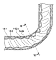
- At least a part of the low-pressure refrigerant pipe 15 is composed of a double pipe 16 shown in FIGS.
- the double pipe 16 has a total length of about 700 to 900 mm and is arranged in the engine room.
- the double pipe 16 includes an outer pipe 161 and an inner pipe 162, and is arranged so that the inner pipe 162 penetrates the inside of the outer pipe 161.
- the outer tube 161 is, for example, a ⁇ 22 mm tube made of aluminum.
- the ⁇ 22 mm tube is a tube having an outer diameter of 22 mm and an inner diameter of 19.6 mm.
- the inner tube 162 is a tube having an outer diameter of 19.1 mm.
- the inner space of the inner tube 162 is an inner flow path 16b.
- the inner / outer channel 16a and the inner channel 16b are refrigerant channels through which refrigerant flows in parallel to each other.
- the inner-outer channel 16a and the inner channel 16b are refrigerant channels having different channel lengths.
- the inner / outer flow path 16a is a first flow path section, and the inner flow path 16b is a second flow path section.
- the inner pipe 162 is, for example, an aluminum 3/4 inch pipe.
- the 3/4 inch tube is a tube having an outer diameter of 19.1 mm and an inner diameter of 16.7 mm.
- the outer diameter of the inner tube 162 is as close as possible to the outer tube 161 while securing the inner / outer flow path 16a. Thereby, the surface area of the inner tube 162 is increased.
- a branch passage 162a is formed at one end of the inner pipe 162 in the longitudinal direction. At the other end in the longitudinal direction of the inner pipe 162, a merging communication hole 162b is formed.
- the diversion communication hole 162a is a diversion part that diverts the flow of the refrigerant into the inner and outer flow paths 16a and the inner flow path 16b.
- the diversion communication hole 162a and the merging communication hole 162b are holes that penetrate the inner pipe 162 in the radial direction.
- the diversion communication hole 162a and the merging communication hole 162b are merging portions that merge the refrigerant that has flowed through the inner and outer flow paths 16a and the inner flow path 16b.
- the outer surface of the inner tube 162 is provided with an inlet groove 162c, an outlet groove 162d, and a spiral groove 162e.
- the inlet groove 162c is a groove extending in the circumferential direction of the inner tube 162 at a portion where the branch flow communication hole 162a is formed on the outer surface of the inner tube 162.
- the outlet groove portion 162d is a groove extending in the circumferential direction of the inner tube 162 at a site where the merge communication hole 162b is formed on the outer surface of the inner tube 162.
- the inlet groove 162c and the outlet groove 162d are grooves extending in the circumferential direction of the inner tube 162.
- the spiral groove 162e is connected to the inlet groove 162c and the outlet groove 162d.
- the spiral groove 162e is a multi-slot (three in this example) groove extending spirally in the longitudinal direction of the inner tube 162 between the inlet groove 162c and the outlet groove 162d.
- ridges 162f are formed between the spiral grooves 162e.
- the outer diameter of the inner tube 162 is substantially maintained.
- the inner / outer flow path 16a is enlarged by the inlet groove 162c, the outlet groove 162d, and the spiral groove 162e.
- the groove depth in the spiral groove 162e is set in a range of 5 to 15% of the outer diameter of the inner tube 162.
- the total length of the spiral groove 162e is set in the range of 300 to 800 mm.
- the inlet groove 162c, the outlet groove 162d, and the spiral groove 162e of the inner pipe 162 are formed by, for example, a grooving tool.
- the spiral groove 162e and the ridge 162f form a wavy wall in the inner tube 162.
- the spiral groove 162e and the ridge 162f form a bellows-like or bowl-like wall in the inner tube 162.
- the inner tube 162 is separated from the inner surface of the outer tube 161. That is, the inner tube 162 is not in contact with the inner surface of the outer tube 161. Only a part of the inner tube 162 in the circumferential direction may be in contact with the inner surface of the outer tube 161.
- the compressor 11 When there is a cooling request from the occupant, the compressor 11 is driven, sucks and compresses the refrigerant from the evaporator 14 side, and then discharges it as a high-temperature high-pressure refrigerant to the condenser 12 side.
- the high-pressure refrigerant is cooled and condensed and liquefied in the condenser 12.
- the refrigerant here is almost in a liquid phase.
- the condensed and liquefied refrigerant is decompressed and expanded by the expansion valve 131 and evaporated by the evaporator 14.
- the refrigerant here is in a substantially saturated gas state with a superheat degree of 0 to 3 ° C.
- the conditioned air is cooled as the refrigerant evaporates.
- the saturated gas refrigerant evaporated in the evaporator 14 flows through the low-pressure refrigerant pipe 15 as a low-temperature low-pressure refrigerant and returns to the compressor 11.
- the low-pressure refrigerant branches into the inner / outer flow path 16a and the inner flow path 16b in the diversion communication hole 162a and flows in parallel to each other, and then merges in the merge communication hole 162b.
- the refrigerant flow on the refrigerant outlet side of the evaporator 14 and the refrigerant suction side of the compressor 11 is divided by the diversion communication hole 162a, and the refrigerant diverted by the diversion communication hole 162a is the internal / external flow path 16a.
- the refrigerant that has flowed through the inner flow path 16b and flowed through the inner-outer flow path 16a and the inner flow path 16b merges at the merge communication hole 162b.
- the inner and outer channel 16a and the inner channel 16b have different channel lengths.
- the pulsation noise can be reduced without using the silencing chamber or the resonance chamber as in Patent Documents 1 and 2, the pulsation noise from the compressor can be reduced while suppressing an increase in mounting space and pressure loss as much as possible. .
- the low-pressure refrigerant pipe 15 includes an outer pipe 161 and an inner pipe 162 that form a double pipe 16, and an inner-outer flow path 16 a is formed between the inner pipe and the outer pipe 161.
- the flow path 16b is formed inside the inner tube.
- the diversion communication hole 162a and the merging communication hole 162b are formed in the inner pipe 162 so as to communicate the inner-outer flow path 16a and the inner flow path 16b. Thereby, the structure of the branching communication hole 162a and the merging communication hole 162b can be simplified.
- the diversion communication hole 162a is disposed at one end (first end) of the inner tube 162, and the merge communication hole 162b is disposed at the other end (second end) of the inner tube 162.
- the refrigerant can be effectively diverted and merged.
- a spiral groove 162e extending in the longitudinal direction of the inner tube 162 is formed on the outer surface of the inner tube 162.
- the spiral groove 162e extends spirally in the longitudinal direction of the inner tube 162. Thereby, the flow path length of the inner-outer flow path 16a can be reliably made different from the inner flow path 16b.
- the diversion communication hole 162a and the merging communication hole 162b are formed at both longitudinal ends of the inner tube 162.
- the diversion communication hole 162a and the merging communication hole In addition to 162b, a plurality of intermediate communication holes 162g are formed in the intermediate portion in the longitudinal direction of the inner tube 162.
- an intermediate communication hole 162g is disposed between the diversion communication hole 162a and the merge communication hole 162b. Thereby, the refrigerant can be reliably divided and merged.
- the double tube 16 extends straight, but in this embodiment, the double tube 16 is bent as shown in FIG.
- the double pipe 16 is formed with a plurality of bent portions 163 in order to avoid interference with the engine and various devices in the engine room, the body, and the like.
- a method for forming the bent portion 163 will be briefly described. First, the inner tube 162 having the inlet groove 162c, the outlet groove 162d, and the spiral groove 162e is inserted into the outer tube 161. Next, both the tubes 161 and 162 are bent at a predetermined portion while the inner tube 162 is positioned inside the outer tube 161. Thereby, the bending part 163 is formed.
- the circular cross section of the outer tube 161 is deformed into a flat shape before the inner tube 162. Therefore, as shown in FIG. 7, the inner wall of the outer tube 161 is in contact with the ridge 162 f, so that the inner tube 162 is clamped and held in the radial direction by the outer tube 161.
- the outer diameter of the inner tube 162 that is, the outer diameter of the peak 162f is in the range of 0.7 to 0.95 times the inner diameter of the outer tube 161, or 0. It should be set within the range of 8 to 0.95 times.
- the groove pitch of the spiral groove 162e the smaller the outer diameter of the peak 162f. Therefore, in order to make the outer diameter of the peak 162f 0.7 times or more the inner diameter of the outer tube 161, the groove pitch Is preferably 12 mm or more. Further, when the inner tube 162 is inserted into the outer tube 161, if the straightness of the inner tube 162 and the outer tube 161 is not firm, it becomes difficult to insert and the productivity deteriorates.
- the diameter is preferably 95% or less with respect to the inner diameter of the outer tube 161.
- the spiral groove 162e and the ridge 162f form a wavy wall in the inner tube 162.
- the wavy wall is contracted by reducing the width of the spiral groove portion 162e and the width of the peak portion 162f.
- the wavy wall is extended by increasing the width of the spiral groove portion 162e and the width of the peak portion 162f.
- the ridge 162 f of the inner pipe 162 comes into contact with the inner wall of the outer pipe 161 at the bending part 163, and the inner pipe 162 is held by being tightened in the radial direction by the outer pipe 161. Therefore, there is an advantage that the outer tube 161 and the inner tube 162 can be fixed with a simple configuration at the bent portion 163 while a flow path between the outer tube 161 and the inner tube 162 is secured by the spiral groove 162e.
- the inner tube 162 can be securely fixed, vibration and resonance between the outer tube 161 and the inner tube 162 can be prevented even when an external force such as vibration is applied from the vehicle, and the two tubes 161 and 162 are prevented from hitting. Thus, it is possible to prevent the generation of abnormal noise and the damage of both tubes 161 and 162 themselves.
- the groove portion of the inner tube 162 is a spiral groove portion 162e, the distortion at the time of bending is reduced while ensuring a flow path between the outer tube 161 and the inner tube 162 in the bending portion 163.
- the bending workability of the inner tube 162 can be improved.
- the strain can be reduced, it is possible to reduce the processing force when bending the double tube 16.
- spiral groove 162e is a multi-groove, even if one spiral groove 162e is crushed by the bent portion 163, the flow path between the outer tube 161 and the inner tube 162 by the other spiral groove 162e. Can be secured. In addition, since the flow path can be enlarged by the multi-row spiral groove 162e, it is possible to reduce the resistance when the refrigerant flows.
- the outer tube 161 and the inner tube 162 are securely fixed at the bent portion 163. be able to.
- the inner tube 162 is firmly fixed in the outer tube 161.
- the inner tube 162 is firmly fixed in the outer tube 161.
- the vibration resistance of the double pipe 160 is improved by providing at least one bent part 163b in the range of 700 mm in the longitudinal direction of the outer pipe 161 and the inner pipe 162.
- the spiral groove portion 162e is not limited to the three-row one, and may be one, two, four, or other groove portions. Moreover, it is good also as a straight groove part extended in the longitudinal direction of the inner pipe
- the outer tube 161 and the inner tube 162 are made of aluminum, but the present invention is not limited to this, and may be made of iron or copper.
- the double pipe 16 disposed in the refrigeration cycle apparatus 10 is applied to a vehicle air conditioner.
- the present invention is not limited to this and is applied to a stationary air conditioner such as a home air conditioner. May be.
- a chlorofluorocarbon refrigerant is used as the refrigerant of the refrigeration cycle apparatus 10, and the high-pressure side refrigerant pressure constitutes a subcritical refrigeration cycle that does not exceed the critical pressure of the refrigerant.
- a supercritical refrigeration cycle in which the high-pressure side refrigerant pressure is equal to or higher than the critical pressure of the refrigerant may be configured.
Landscapes
- Engineering & Computer Science (AREA)
- Mechanical Engineering (AREA)
- General Engineering & Computer Science (AREA)
- Physics & Mathematics (AREA)
- Thermal Sciences (AREA)
- Compressor (AREA)
- Air-Conditioning For Vehicles (AREA)
Abstract
Une tuyauterie de réfrigérant selon un premier aspect de la présente invention est pourvue de parties de division (162a, 162g), d'une première partie de passage d'écoulement (16a), d'une seconde partie de passage d'écoulement (16b) et de parties de fusion (162b, 162g). Les parties de division divisent l'écoulement d'un réfrigérant au niveau d'un côté de sortie de réfrigérant d'un évaporateur (14) d'un cycle de réfrigération (10) et au niveau d'un côté d'entrée de réfrigérant d'un compresseur (11) du cycle de réfrigération. Dans la première partie de passage d'écoulement et la seconde partie de passage d'écoulement, les réfrigérants divisés dans la partie de division s'écoulent en parallèle l'un par rapport à l'autre. Les réfrigérants s'écoulant à travers la première partie de passage d'écoulement et la seconde partie de passage d'écoulement se fusionnent au niveau de la partie de fusion. La première partie de passage d'écoulement et la seconde partie de passage d'écoulement ont des longueurs de passage d'écoulement différentes l'une de l'autre. Conformément à la tuyauterie de réfrigérant, étant donné que les longueurs de passage d'écoulement de la première partie de passage d'écoulement et de la seconde partie de passage d'écoulement sont différentes l'une de l'autre, une différence de phase est générée entre les pulsations du flux de réfrigérant de la première partie de passage d'écoulement et du flux de réfrigérant de la seconde partie de passage d'écoulement, et un effet dans lequel les pulsations s'annulent mutuellement. Au final, le bruit de pulsation peut être réduit. De plus, le bruit de pulsation provenant du compresseur peut être réduit tout en supprimant au maximum une augmentation de l'espace de montage ou de la perte de pression.
Priority Applications (3)
| Application Number | Priority Date | Filing Date | Title |
|---|---|---|---|
| CN201880010238.9A CN110249189A (zh) | 2017-02-07 | 2018-01-23 | 制冷剂配管和制冷循环装置 |
| DE112018000718.9T DE112018000718T5 (de) | 2017-02-07 | 2018-01-23 | Kältemittelrohr und Kühlkreislaufgerät |
| US16/524,399 US20190345937A1 (en) | 2017-02-07 | 2019-07-29 | Refrigerant pipe and refrigeration cycle device |
Applications Claiming Priority (2)
| Application Number | Priority Date | Filing Date | Title |
|---|---|---|---|
| JP2017020265A JP6737196B2 (ja) | 2017-02-07 | 2017-02-07 | 冷媒配管および冷凍サイクル装置 |
| JP2017-020265 | 2017-09-15 |
Related Child Applications (1)
| Application Number | Title | Priority Date | Filing Date |
|---|---|---|---|
| US16/524,399 Continuation US20190345937A1 (en) | 2017-02-07 | 2019-07-29 | Refrigerant pipe and refrigeration cycle device |
Publications (1)
| Publication Number | Publication Date |
|---|---|
| WO2018147063A1 true WO2018147063A1 (fr) | 2018-08-16 |
Family
ID=63107343
Family Applications (1)
| Application Number | Title | Priority Date | Filing Date |
|---|---|---|---|
| PCT/JP2018/001845 WO2018147063A1 (fr) | 2017-02-07 | 2018-01-23 | Tuyauterie de réfrigérant et appareil à cycle de réfrigération |
Country Status (5)
| Country | Link |
|---|---|
| US (1) | US20190345937A1 (fr) |
| JP (1) | JP6737196B2 (fr) |
| CN (1) | CN110249189A (fr) |
| DE (1) | DE112018000718T5 (fr) |
| WO (1) | WO2018147063A1 (fr) |
Families Citing this family (5)
| Publication number | Priority date | Publication date | Assignee | Title |
|---|---|---|---|---|
| CN110476024B (zh) * | 2018-03-09 | 2021-10-22 | 日立江森自控空调有限公司 | 冷冻循环装置 |
| CN109236610A (zh) * | 2018-10-16 | 2019-01-18 | 杭州钱江制冷压缩机集团有限公司 | 新型压缩机消音器 |
| CN111140467A (zh) * | 2020-01-14 | 2020-05-12 | 福建启盛实验设备科技有限公司 | 一种中央切片冷台工作系统 |
| CN113757124B (zh) * | 2021-10-26 | 2023-04-11 | 广东美芝制冷设备有限公司 | 压缩机和制冷设备 |
| CN116251255B (zh) * | 2023-05-15 | 2023-07-14 | 四川省医学科学院·四川省人民医院 | 一种具有加温功能的膀胱冲洗装置 |
Citations (7)
| Publication number | Priority date | Publication date | Assignee | Title |
|---|---|---|---|---|
| JPH09112245A (ja) * | 1995-10-20 | 1997-04-28 | Carrier Corp | マフラーおよびマフラーの組み立て方法 |
| JP2005283010A (ja) * | 2004-03-30 | 2005-10-13 | Mitsubishi Electric Corp | 流路装置、冷凍サイクル装置、圧力脈動低減装置、圧力脈動低減方法 |
| JP2008050989A (ja) * | 2006-08-24 | 2008-03-06 | Denso Corp | 消音器 |
| JP2009097784A (ja) * | 2007-10-16 | 2009-05-07 | Denso Corp | 配管装置及びそれを備えた冷凍サイクル装置並びにその製造方法 |
| JP2011185207A (ja) * | 2010-03-10 | 2011-09-22 | Toyota Motor Corp | 消音器 |
| JP2015063895A (ja) * | 2013-09-24 | 2015-04-09 | 株式会社豊田自動織機 | 冷凍サイクルにおける脈動圧低減装置 |
| US20160084521A1 (en) * | 2013-08-23 | 2016-03-24 | Halla Visteon Climate Control Corp | Silencer for a vehicle air conditioning system |
Family Cites Families (12)
| Publication number | Priority date | Publication date | Assignee | Title |
|---|---|---|---|---|
| JPS5194538U (fr) * | 1975-01-29 | 1976-07-29 | ||
| JPS52125644U (fr) * | 1976-03-22 | 1977-09-24 | ||
| JPH0633918B2 (ja) * | 1987-10-20 | 1994-05-02 | 三菱電機株式会社 | 冷蔵庫 |
| JPH02309095A (ja) * | 1989-05-22 | 1990-12-25 | Tokai Rubber Ind Ltd | 脈動吸収管 |
| JPH0681627A (ja) * | 1992-09-03 | 1994-03-22 | Tanaka Pipe:Kk | エンジン用排気消音器 |
| JPH06147624A (ja) * | 1992-10-30 | 1994-05-27 | Sanbetsuku Kk | 送風ダクトの消音ボックス |
| JPH1163733A (ja) * | 1997-08-27 | 1999-03-05 | Mitsubishi Heavy Ind Ltd | 冷凍装置 |
| JP2001004250A (ja) * | 1999-06-23 | 2001-01-12 | Kobo Koki:Kk | 流体回路用振動減衰器と冷凍回路用の配管構造 |
| KR100474908B1 (ko) * | 2002-06-12 | 2005-03-08 | 엘지전자 주식회사 | 공기조화기의 냉난방 시스템 |
| CN100460794C (zh) * | 2004-11-09 | 2009-02-11 | 株式会社电装 | 双壁管及其制造方法和设有双壁管的制冷剂循环装置 |
| JP4659066B2 (ja) * | 2008-05-26 | 2011-03-30 | 三菱電機株式会社 | 流路装置 |
| CN105909598A (zh) * | 2016-05-12 | 2016-08-31 | 绍兴文理学院 | 一种全频段液压系统压力脉动抑制装置 |
-
2017
- 2017-02-07 JP JP2017020265A patent/JP6737196B2/ja active Active
-
2018
- 2018-01-23 CN CN201880010238.9A patent/CN110249189A/zh active Pending
- 2018-01-23 WO PCT/JP2018/001845 patent/WO2018147063A1/fr active Application Filing
- 2018-01-23 DE DE112018000718.9T patent/DE112018000718T5/de active Pending
-
2019
- 2019-07-29 US US16/524,399 patent/US20190345937A1/en not_active Abandoned
Patent Citations (7)
| Publication number | Priority date | Publication date | Assignee | Title |
|---|---|---|---|---|
| JPH09112245A (ja) * | 1995-10-20 | 1997-04-28 | Carrier Corp | マフラーおよびマフラーの組み立て方法 |
| JP2005283010A (ja) * | 2004-03-30 | 2005-10-13 | Mitsubishi Electric Corp | 流路装置、冷凍サイクル装置、圧力脈動低減装置、圧力脈動低減方法 |
| JP2008050989A (ja) * | 2006-08-24 | 2008-03-06 | Denso Corp | 消音器 |
| JP2009097784A (ja) * | 2007-10-16 | 2009-05-07 | Denso Corp | 配管装置及びそれを備えた冷凍サイクル装置並びにその製造方法 |
| JP2011185207A (ja) * | 2010-03-10 | 2011-09-22 | Toyota Motor Corp | 消音器 |
| US20160084521A1 (en) * | 2013-08-23 | 2016-03-24 | Halla Visteon Climate Control Corp | Silencer for a vehicle air conditioning system |
| JP2015063895A (ja) * | 2013-09-24 | 2015-04-09 | 株式会社豊田自動織機 | 冷凍サイクルにおける脈動圧低減装置 |
Also Published As
| Publication number | Publication date |
|---|---|
| DE112018000718T5 (de) | 2019-11-21 |
| JP6737196B2 (ja) | 2020-08-05 |
| US20190345937A1 (en) | 2019-11-14 |
| CN110249189A (zh) | 2019-09-17 |
| JP2018128180A (ja) | 2018-08-16 |
Similar Documents
| Publication | Publication Date | Title |
|---|---|---|
| WO2018147063A1 (fr) | Tuyauterie de réfrigérant et appareil à cycle de réfrigération | |
| US9669499B2 (en) | Double-wall pipe, method of manufacturing the same and refrigerant cycle device provided with the same | |
| US20070251265A1 (en) | Piping structure with inner heat exchanger and refrigeration cycle device having the same | |
| JP2005308384A (ja) | エジェクタサイクル | |
| JP2006162241A (ja) | 二重管、その製造方法、およびそれを備える冷凍サイクル装置 | |
| JP7156413B2 (ja) | 内部熱交換器 | |
| JP2006132905A (ja) | 冷凍サイクル | |
| JP2009097784A (ja) | 配管装置及びそれを備えた冷凍サイクル装置並びにその製造方法 | |
| WO2017159542A1 (fr) | Tuyau double | |
| KR20150069354A (ko) | 차량용 에어컨시스템 | |
| WO2019150968A1 (fr) | Échangeur de chaleur de type à double tube | |
| KR20150072610A (ko) | 차량 공조장치용 소음기 | |
| JP2010127498A (ja) | 冷凍サイクル装置 | |
| KR101544882B1 (ko) | 차량용 에어컨의 냉방시스템 | |
| KR101487202B1 (ko) | 차량용 공조장치의 소음기 | |
| US20130299143A1 (en) | Internal heat exchanger | |
| JP2018124024A (ja) | 凝縮器 | |
| JP2009204183A (ja) | 冷凍サイクル装置 | |
| KR20080038784A (ko) | 자동차 공조장치용 소음기 | |
| JP2008281338A (ja) | エジェクタサイクル | |
| KR102365018B1 (ko) | 차량용 공조장치 | |
| WO2020116271A1 (fr) | Échangeur de chaleur interne et dispositif à cycle frigorifique doté de celui-ci | |
| JP2021188788A (ja) | 内部熱交換器の製造方法 | |
| KR20210025749A (ko) | 냉매 배관 시스템 | |
| KR20090029890A (ko) | 이중관형 내부 열교환기 |
Legal Events
| Date | Code | Title | Description |
|---|---|---|---|
| 121 | Ep: the epo has been informed by wipo that ep was designated in this application |
Ref document number: 18751327 Country of ref document: EP Kind code of ref document: A1 |
|
| 122 | Ep: pct application non-entry in european phase |
Ref document number: 18751327 Country of ref document: EP Kind code of ref document: A1 |