WO2018147063A1 - Refrigerant piping and refrigeration cycle apparatus - Google Patents
Refrigerant piping and refrigeration cycle apparatus Download PDFInfo
- Publication number
- WO2018147063A1 WO2018147063A1 PCT/JP2018/001845 JP2018001845W WO2018147063A1 WO 2018147063 A1 WO2018147063 A1 WO 2018147063A1 JP 2018001845 W JP2018001845 W JP 2018001845W WO 2018147063 A1 WO2018147063 A1 WO 2018147063A1
- Authority
- WO
- WIPO (PCT)
- Prior art keywords
- refrigerant
- flow path
- pipe
- refrigeration cycle
- flow
- Prior art date
Links
Images


Classifications
-
- B—PERFORMING OPERATIONS; TRANSPORTING
- B60—VEHICLES IN GENERAL
- B60H—ARRANGEMENTS OF HEATING, COOLING, VENTILATING OR OTHER AIR-TREATING DEVICES SPECIALLY ADAPTED FOR PASSENGER OR GOODS SPACES OF VEHICLES
- B60H1/00—Heating, cooling or ventilating [HVAC] devices
- B60H1/00507—Details, e.g. mounting arrangements, desaeration devices
- B60H1/00557—Details of ducts or cables
- B60H1/00571—Details of ducts or cables of liquid ducts, e.g. for coolant liquids or refrigerants
-
- B—PERFORMING OPERATIONS; TRANSPORTING
- B60—VEHICLES IN GENERAL
- B60H—ARRANGEMENTS OF HEATING, COOLING, VENTILATING OR OTHER AIR-TREATING DEVICES SPECIALLY ADAPTED FOR PASSENGER OR GOODS SPACES OF VEHICLES
- B60H1/00—Heating, cooling or ventilating [HVAC] devices
- B60H1/00642—Control systems or circuits; Control members or indication devices for heating, cooling or ventilating devices
- B60H1/00814—Control systems or circuits characterised by their output, for controlling particular components of the heating, cooling or ventilating installation
- B60H1/00878—Control systems or circuits characterised by their output, for controlling particular components of the heating, cooling or ventilating installation the components being temperature regulating devices
- B60H1/00899—Controlling the flow of liquid in a heat pump system
-
- F—MECHANICAL ENGINEERING; LIGHTING; HEATING; WEAPONS; BLASTING
- F04—POSITIVE - DISPLACEMENT MACHINES FOR LIQUIDS; PUMPS FOR LIQUIDS OR ELASTIC FLUIDS
- F04B—POSITIVE-DISPLACEMENT MACHINES FOR LIQUIDS; PUMPS
- F04B39/00—Component parts, details, or accessories, of pumps or pumping systems specially adapted for elastic fluids, not otherwise provided for in, or of interest apart from, groups F04B25/00 - F04B37/00
- F04B39/12—Casings; Cylinders; Cylinder heads; Fluid connections
-
- F—MECHANICAL ENGINEERING; LIGHTING; HEATING; WEAPONS; BLASTING
- F04—POSITIVE - DISPLACEMENT MACHINES FOR LIQUIDS; PUMPS FOR LIQUIDS OR ELASTIC FLUIDS
- F04C—ROTARY-PISTON, OR OSCILLATING-PISTON, POSITIVE-DISPLACEMENT MACHINES FOR LIQUIDS; ROTARY-PISTON, OR OSCILLATING-PISTON, POSITIVE-DISPLACEMENT PUMPS
- F04C23/00—Combinations of two or more pumps, each being of rotary-piston or oscillating-piston type, specially adapted for elastic fluids; Pumping installations specially adapted for elastic fluids; Multi-stage pumps specially adapted for elastic fluids
- F04C23/008—Hermetic pumps
-
- F—MECHANICAL ENGINEERING; LIGHTING; HEATING; WEAPONS; BLASTING
- F16—ENGINEERING ELEMENTS AND UNITS; GENERAL MEASURES FOR PRODUCING AND MAINTAINING EFFECTIVE FUNCTIONING OF MACHINES OR INSTALLATIONS; THERMAL INSULATION IN GENERAL
- F16L—PIPES; JOINTS OR FITTINGS FOR PIPES; SUPPORTS FOR PIPES, CABLES OR PROTECTIVE TUBING; MEANS FOR THERMAL INSULATION IN GENERAL
- F16L11/00—Hoses, i.e. flexible pipes
- F16L11/22—Multi-channel hoses
-
- F—MECHANICAL ENGINEERING; LIGHTING; HEATING; WEAPONS; BLASTING
- F16—ENGINEERING ELEMENTS AND UNITS; GENERAL MEASURES FOR PRODUCING AND MAINTAINING EFFECTIVE FUNCTIONING OF MACHINES OR INSTALLATIONS; THERMAL INSULATION IN GENERAL
- F16L—PIPES; JOINTS OR FITTINGS FOR PIPES; SUPPORTS FOR PIPES, CABLES OR PROTECTIVE TUBING; MEANS FOR THERMAL INSULATION IN GENERAL
- F16L55/00—Devices or appurtenances for use in, or in connection with, pipes or pipe systems
- F16L55/04—Devices damping pulsations or vibrations in fluids
-
- F—MECHANICAL ENGINEERING; LIGHTING; HEATING; WEAPONS; BLASTING
- F16—ENGINEERING ELEMENTS AND UNITS; GENERAL MEASURES FOR PRODUCING AND MAINTAINING EFFECTIVE FUNCTIONING OF MACHINES OR INSTALLATIONS; THERMAL INSULATION IN GENERAL
- F16L—PIPES; JOINTS OR FITTINGS FOR PIPES; SUPPORTS FOR PIPES, CABLES OR PROTECTIVE TUBING; MEANS FOR THERMAL INSULATION IN GENERAL
- F16L9/00—Rigid pipes
- F16L9/18—Double-walled pipes; Multi-channel pipes or pipe assemblies
-
- F—MECHANICAL ENGINEERING; LIGHTING; HEATING; WEAPONS; BLASTING
- F25—REFRIGERATION OR COOLING; COMBINED HEATING AND REFRIGERATION SYSTEMS; HEAT PUMP SYSTEMS; MANUFACTURE OR STORAGE OF ICE; LIQUEFACTION SOLIDIFICATION OF GASES
- F25B—REFRIGERATION MACHINES, PLANTS OR SYSTEMS; COMBINED HEATING AND REFRIGERATION SYSTEMS; HEAT PUMP SYSTEMS
- F25B30/00—Heat pumps
- F25B30/02—Heat pumps of the compression type
-
- F—MECHANICAL ENGINEERING; LIGHTING; HEATING; WEAPONS; BLASTING
- F25—REFRIGERATION OR COOLING; COMBINED HEATING AND REFRIGERATION SYSTEMS; HEAT PUMP SYSTEMS; MANUFACTURE OR STORAGE OF ICE; LIQUEFACTION SOLIDIFICATION OF GASES
- F25B—REFRIGERATION MACHINES, PLANTS OR SYSTEMS; COMBINED HEATING AND REFRIGERATION SYSTEMS; HEAT PUMP SYSTEMS
- F25B41/00—Fluid-circulation arrangements
- F25B41/40—Fluid line arrangements
- F25B41/42—Arrangements for diverging or converging flows, e.g. branch lines or junctions
-
- B—PERFORMING OPERATIONS; TRANSPORTING
- B60—VEHICLES IN GENERAL
- B60H—ARRANGEMENTS OF HEATING, COOLING, VENTILATING OR OTHER AIR-TREATING DEVICES SPECIALLY ADAPTED FOR PASSENGER OR GOODS SPACES OF VEHICLES
- B60H1/00—Heating, cooling or ventilating [HVAC] devices
- B60H1/00507—Details, e.g. mounting arrangements, desaeration devices
- B60H2001/006—Noise reduction
-
- F—MECHANICAL ENGINEERING; LIGHTING; HEATING; WEAPONS; BLASTING
- F25—REFRIGERATION OR COOLING; COMBINED HEATING AND REFRIGERATION SYSTEMS; HEAT PUMP SYSTEMS; MANUFACTURE OR STORAGE OF ICE; LIQUEFACTION SOLIDIFICATION OF GASES
- F25B—REFRIGERATION MACHINES, PLANTS OR SYSTEMS; COMBINED HEATING AND REFRIGERATION SYSTEMS; HEAT PUMP SYSTEMS
- F25B2500/00—Problems to be solved
- F25B2500/12—Sound
Definitions
- the present disclosure relates to a refrigerant pipe used in a refrigeration cycle and a refrigeration cycle apparatus including the refrigerant pipe.
- Patent Documents 1 and 2 describe a silencer used in a refrigeration cycle. This silencer reduces the drive noise and pulsation noise of the compressor transmitted to the refrigerant in the refrigeration cycle, and is disposed in the middle of the low-pressure refrigerant pipe on the compressor suction side.
- the silencer of Patent Document 1 is called a straight type.
- the silencer of Patent Document 1 is a silencer formed by forming a silencer chamber in a bulging shape between an inlet pipe and an outlet pipe.
- the silencer of Patent Document 2 is called an elbow type.
- the silencer of Patent Document 2 is a silencer for a hermetic compressor, and the silencer is disposed in the internal space of the hermetic compressor and the refrigerant suction path leading from the suction pipe to the compressor, thereby The generated pulsating sound is attenuated by the silencer.
- a communication pipe that connects between the internal space of the compressor and the compression unit is disposed through the resonance chamber formed in a sealed structure, and the communication pipe is connected to the communication pipe.
- a resonance hole is formed in the resonance chamber to form a resonance type silencing structure.
- JP 2002-61508 A Japanese Patent Laid-Open No. 11-62827
- the above silencer is arranged in the engine room of the vehicle. Since the silencer has a silencer chamber and a resonance chamber, a mounting space for the engine room becomes large. Therefore, it may not be easy to secure a mounting space for the silencer, for example, the silencer may interfere with other mounted parts in the engine room.
- the present disclosure aims to reduce pulsation noise from the compressor while suppressing increase in mounting space and pressure loss as much as possible.
- the refrigerant pipe according to the first aspect of the present disclosure includes a flow dividing section, a first flow path section, a second flow path section, and a merge section.
- the diversion unit diverts the refrigerant flow on the refrigerant outlet side of the evaporator of the refrigeration cycle and on the refrigerant suction side of the compressor of the refrigeration cycle.
- the refrigerant diverted in the diversion part flows in parallel with each other.
- the refrigerant that has flowed through the first flow path portion and the second flow path portion merges at the merge portion.
- the first channel portion and the second channel portion have different channel lengths.
- the pulsation noise can be reduced without using the silencer chamber and the resonance chamber described in Patent Documents 1 and 2, the pulsation noise from the compressor can be reduced while suppressing an increase in mounting space and pressure loss as much as possible. .
- the refrigeration cycle apparatus includes a compressor, a radiator, a decompression unit, an evaporator, and a low-pressure refrigerant pipe.
- the compressor sucks in refrigerant, compresses it, and discharges it.
- the radiator dissipates heat from the refrigerant discharged by the compressor.
- the decompression unit decompresses the refrigerant radiated by the radiator.
- the evaporator evaporates the refrigerant decompressed by the decompression unit.
- the refrigerant on the refrigerant outlet side of the evaporator and the refrigerant suction side of the compressor flows through the low-pressure refrigerant pipe.
- the low-pressure refrigerant pipe has a diversion part, a first flow path part and a second flow path part, and a merge part.
- the diversion unit diverts the refrigerant flow.
- the refrigerant diverted in the diversion part flows in parallel with each other.
- the refrigerant that has flowed through the first flow path portion and the second flow path portion merges at the merge portion.
- the first channel portion and the second channel portion have different channel lengths.
- a refrigeration cycle apparatus 10 shown in FIG. 1 is applied to a vehicle air conditioner.
- the refrigeration cycle apparatus 10 is a vapor compression refrigerator that includes a compressor 11, a condenser 12, an expansion valve 13, and an evaporator 14.
- a chlorofluorocarbon refrigerant is used as the refrigerant, and a subcritical refrigeration cycle in which the high-pressure side refrigerant pressure does not exceed the critical pressure of the refrigerant is configured.
- the compressor 11, the condenser 12, the expansion valve 13 and the evaporator 14 are arranged in series with each other in the refrigerant flow.
- the compressor 11 sucks in the refrigerant of the refrigeration cycle apparatus 10, compresses it, and discharges it.
- the compressor 11 is a belt-driven compressor or an electric compressor.
- a belt-driven compressor is a compressor that is driven by the driving force of an engine being transmitted through a belt.
- the electric compressor is an electric compressor driven by electric power supplied from a battery.
- the compressor 11 is disposed in the engine room.
- the condenser 12 is a radiator that condenses the high-pressure side refrigerant by causing the high-pressure side refrigerant to dissipate heat to the outside air by exchanging heat between the high-pressure side refrigerant discharged from the compressor 11 and the outside air.
- the condenser 12 is disposed at the forefront in the engine room.
- the expansion valve 13 is a decompression unit that decompresses and expands the liquid-phase refrigerant that has flowed out of the condenser 12.
- the expansion valve 13 has a temperature sensing part.
- the temperature sensing unit detects the degree of superheat of the evaporator 14 outlet-side refrigerant based on the temperature and pressure of the evaporator 14 outlet-side refrigerant.
- the expansion valve 13 is a temperature type expansion valve that adjusts the throttle passage area by a mechanical mechanism so that the degree of superheat of the refrigerant on the outlet side of the evaporator 14 falls within a predetermined range.
- the expansion valve 13 may be an electric expansion valve that adjusts the throttle passage area by an electric mechanism.
- the evaporator 14 heat-exchanges the low-pressure refrigerant that has flowed out of the expansion valve 13 and the air blown into the passenger compartment, thereby evaporating the low-pressure refrigerant and cooling the air blown into the passenger compartment. It is.
- the gas-phase refrigerant evaporated in the evaporator 14 is sucked into the compressor 11 through the low-pressure refrigerant pipe 15 and compressed.
- the evaporator 14 is housed in a casing (hereinafter referred to as an air conditioning casing) of an indoor air conditioning unit (not shown).
- the indoor air conditioning unit is disposed inside an instrument panel (not shown) at the front of the vehicle interior.
- the air conditioning casing is an air passage forming member that forms an air passage.
- a heater core (not shown) is arranged on the downstream side of the air flow of the evaporator 14.
- the heater core is an air heating heat exchanger that heats air blown into the vehicle interior by exchanging heat between the engine coolant and the air blown into the vehicle interior.
- an inside / outside air switching box (not shown) and an indoor fan (not shown) are arranged.
- the inside / outside air switching box is an inside / outside air switching unit that switches between introduction of inside air and outside air into an air passage in the air conditioning casing.
- the indoor blower sucks and blows the inside air and the outside air introduced into the air passage in the air conditioning casing through the inside / outside air switching box.
- An air mix door (not shown) is arranged between the evaporator 14 and the heater core in the air passage in the air conditioning casing.
- the air mix door adjusts the air volume ratio between the cold air that has passed through the evaporator 14 and the cold air that flows into the heater core and the cold air that flows by bypassing the heater core.
- the air mix door is a rotary door having a rotary shaft that is rotatably supported with respect to the air conditioning casing, and a door base plate portion coupled to the rotary shaft.
- a plurality of blowout openings are formed in the most downstream portion of the airflow of the air conditioning casing.
- the conditioned air whose temperature has been adjusted by the air conditioning casing is blown out into the vehicle interior, which is the air-conditioning target space, through these blowout openings.
- An air outlet mode switching door (not shown) is arranged on the upstream side of the air flow in the air outlet.
- the outlet mode switching door switches the outlet mode.
- a blower outlet mode there are a face mode, a bi-level mode, a foot mode, and the like.
- At least a part of the low-pressure refrigerant pipe 15 is composed of a double pipe 16 shown in FIGS.
- the double pipe 16 has a total length of about 700 to 900 mm and is arranged in the engine room.
- the double pipe 16 includes an outer pipe 161 and an inner pipe 162, and is arranged so that the inner pipe 162 penetrates the inside of the outer pipe 161.
- the outer tube 161 is, for example, a ⁇ 22 mm tube made of aluminum.
- the ⁇ 22 mm tube is a tube having an outer diameter of 22 mm and an inner diameter of 19.6 mm.
- the inner tube 162 is a tube having an outer diameter of 19.1 mm.
- the inner space of the inner tube 162 is an inner flow path 16b.
- the inner / outer channel 16a and the inner channel 16b are refrigerant channels through which refrigerant flows in parallel to each other.
- the inner-outer channel 16a and the inner channel 16b are refrigerant channels having different channel lengths.
- the inner / outer flow path 16a is a first flow path section, and the inner flow path 16b is a second flow path section.
- the inner pipe 162 is, for example, an aluminum 3/4 inch pipe.
- the 3/4 inch tube is a tube having an outer diameter of 19.1 mm and an inner diameter of 16.7 mm.
- the outer diameter of the inner tube 162 is as close as possible to the outer tube 161 while securing the inner / outer flow path 16a. Thereby, the surface area of the inner tube 162 is increased.
- a branch passage 162a is formed at one end of the inner pipe 162 in the longitudinal direction. At the other end in the longitudinal direction of the inner pipe 162, a merging communication hole 162b is formed.
- the diversion communication hole 162a is a diversion part that diverts the flow of the refrigerant into the inner and outer flow paths 16a and the inner flow path 16b.
- the diversion communication hole 162a and the merging communication hole 162b are holes that penetrate the inner pipe 162 in the radial direction.
- the diversion communication hole 162a and the merging communication hole 162b are merging portions that merge the refrigerant that has flowed through the inner and outer flow paths 16a and the inner flow path 16b.
- the outer surface of the inner tube 162 is provided with an inlet groove 162c, an outlet groove 162d, and a spiral groove 162e.
- the inlet groove 162c is a groove extending in the circumferential direction of the inner tube 162 at a portion where the branch flow communication hole 162a is formed on the outer surface of the inner tube 162.
- the outlet groove portion 162d is a groove extending in the circumferential direction of the inner tube 162 at a site where the merge communication hole 162b is formed on the outer surface of the inner tube 162.
- the inlet groove 162c and the outlet groove 162d are grooves extending in the circumferential direction of the inner tube 162.
- the spiral groove 162e is connected to the inlet groove 162c and the outlet groove 162d.
- the spiral groove 162e is a multi-slot (three in this example) groove extending spirally in the longitudinal direction of the inner tube 162 between the inlet groove 162c and the outlet groove 162d.
- ridges 162f are formed between the spiral grooves 162e.
- the outer diameter of the inner tube 162 is substantially maintained.
- the inner / outer flow path 16a is enlarged by the inlet groove 162c, the outlet groove 162d, and the spiral groove 162e.
- the groove depth in the spiral groove 162e is set in a range of 5 to 15% of the outer diameter of the inner tube 162.
- the total length of the spiral groove 162e is set in the range of 300 to 800 mm.
- the inlet groove 162c, the outlet groove 162d, and the spiral groove 162e of the inner pipe 162 are formed by, for example, a grooving tool.
- the spiral groove 162e and the ridge 162f form a wavy wall in the inner tube 162.
- the spiral groove 162e and the ridge 162f form a bellows-like or bowl-like wall in the inner tube 162.
- the inner tube 162 is separated from the inner surface of the outer tube 161. That is, the inner tube 162 is not in contact with the inner surface of the outer tube 161. Only a part of the inner tube 162 in the circumferential direction may be in contact with the inner surface of the outer tube 161.
- the compressor 11 When there is a cooling request from the occupant, the compressor 11 is driven, sucks and compresses the refrigerant from the evaporator 14 side, and then discharges it as a high-temperature high-pressure refrigerant to the condenser 12 side.
- the high-pressure refrigerant is cooled and condensed and liquefied in the condenser 12.
- the refrigerant here is almost in a liquid phase.
- the condensed and liquefied refrigerant is decompressed and expanded by the expansion valve 131 and evaporated by the evaporator 14.
- the refrigerant here is in a substantially saturated gas state with a superheat degree of 0 to 3 ° C.
- the conditioned air is cooled as the refrigerant evaporates.
- the saturated gas refrigerant evaporated in the evaporator 14 flows through the low-pressure refrigerant pipe 15 as a low-temperature low-pressure refrigerant and returns to the compressor 11.
- the low-pressure refrigerant branches into the inner / outer flow path 16a and the inner flow path 16b in the diversion communication hole 162a and flows in parallel to each other, and then merges in the merge communication hole 162b.
- the refrigerant flow on the refrigerant outlet side of the evaporator 14 and the refrigerant suction side of the compressor 11 is divided by the diversion communication hole 162a, and the refrigerant diverted by the diversion communication hole 162a is the internal / external flow path 16a.
- the refrigerant that has flowed through the inner flow path 16b and flowed through the inner-outer flow path 16a and the inner flow path 16b merges at the merge communication hole 162b.
- the inner and outer channel 16a and the inner channel 16b have different channel lengths.
- the pulsation noise can be reduced without using the silencing chamber or the resonance chamber as in Patent Documents 1 and 2, the pulsation noise from the compressor can be reduced while suppressing an increase in mounting space and pressure loss as much as possible. .
- the low-pressure refrigerant pipe 15 includes an outer pipe 161 and an inner pipe 162 that form a double pipe 16, and an inner-outer flow path 16 a is formed between the inner pipe and the outer pipe 161.
- the flow path 16b is formed inside the inner tube.
- the diversion communication hole 162a and the merging communication hole 162b are formed in the inner pipe 162 so as to communicate the inner-outer flow path 16a and the inner flow path 16b. Thereby, the structure of the branching communication hole 162a and the merging communication hole 162b can be simplified.
- the diversion communication hole 162a is disposed at one end (first end) of the inner tube 162, and the merge communication hole 162b is disposed at the other end (second end) of the inner tube 162.
- the refrigerant can be effectively diverted and merged.
- a spiral groove 162e extending in the longitudinal direction of the inner tube 162 is formed on the outer surface of the inner tube 162.
- the spiral groove 162e extends spirally in the longitudinal direction of the inner tube 162. Thereby, the flow path length of the inner-outer flow path 16a can be reliably made different from the inner flow path 16b.
- the diversion communication hole 162a and the merging communication hole 162b are formed at both longitudinal ends of the inner tube 162.
- the diversion communication hole 162a and the merging communication hole In addition to 162b, a plurality of intermediate communication holes 162g are formed in the intermediate portion in the longitudinal direction of the inner tube 162.
- an intermediate communication hole 162g is disposed between the diversion communication hole 162a and the merge communication hole 162b. Thereby, the refrigerant can be reliably divided and merged.
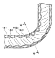
- the double tube 16 extends straight, but in this embodiment, the double tube 16 is bent as shown in FIG.
- the double pipe 16 is formed with a plurality of bent portions 163 in order to avoid interference with the engine and various devices in the engine room, the body, and the like.
- a method for forming the bent portion 163 will be briefly described. First, the inner tube 162 having the inlet groove 162c, the outlet groove 162d, and the spiral groove 162e is inserted into the outer tube 161. Next, both the tubes 161 and 162 are bent at a predetermined portion while the inner tube 162 is positioned inside the outer tube 161. Thereby, the bending part 163 is formed.
- the circular cross section of the outer tube 161 is deformed into a flat shape before the inner tube 162. Therefore, as shown in FIG. 7, the inner wall of the outer tube 161 is in contact with the ridge 162 f, so that the inner tube 162 is clamped and held in the radial direction by the outer tube 161.
- the outer diameter of the inner tube 162 that is, the outer diameter of the peak 162f is in the range of 0.7 to 0.95 times the inner diameter of the outer tube 161, or 0. It should be set within the range of 8 to 0.95 times.
- the groove pitch of the spiral groove 162e the smaller the outer diameter of the peak 162f. Therefore, in order to make the outer diameter of the peak 162f 0.7 times or more the inner diameter of the outer tube 161, the groove pitch Is preferably 12 mm or more. Further, when the inner tube 162 is inserted into the outer tube 161, if the straightness of the inner tube 162 and the outer tube 161 is not firm, it becomes difficult to insert and the productivity deteriorates.
- the diameter is preferably 95% or less with respect to the inner diameter of the outer tube 161.
- the spiral groove 162e and the ridge 162f form a wavy wall in the inner tube 162.
- the wavy wall is contracted by reducing the width of the spiral groove portion 162e and the width of the peak portion 162f.
- the wavy wall is extended by increasing the width of the spiral groove portion 162e and the width of the peak portion 162f.
- the ridge 162 f of the inner pipe 162 comes into contact with the inner wall of the outer pipe 161 at the bending part 163, and the inner pipe 162 is held by being tightened in the radial direction by the outer pipe 161. Therefore, there is an advantage that the outer tube 161 and the inner tube 162 can be fixed with a simple configuration at the bent portion 163 while a flow path between the outer tube 161 and the inner tube 162 is secured by the spiral groove 162e.
- the inner tube 162 can be securely fixed, vibration and resonance between the outer tube 161 and the inner tube 162 can be prevented even when an external force such as vibration is applied from the vehicle, and the two tubes 161 and 162 are prevented from hitting. Thus, it is possible to prevent the generation of abnormal noise and the damage of both tubes 161 and 162 themselves.
- the groove portion of the inner tube 162 is a spiral groove portion 162e, the distortion at the time of bending is reduced while ensuring a flow path between the outer tube 161 and the inner tube 162 in the bending portion 163.
- the bending workability of the inner tube 162 can be improved.
- the strain can be reduced, it is possible to reduce the processing force when bending the double tube 16.
- spiral groove 162e is a multi-groove, even if one spiral groove 162e is crushed by the bent portion 163, the flow path between the outer tube 161 and the inner tube 162 by the other spiral groove 162e. Can be secured. In addition, since the flow path can be enlarged by the multi-row spiral groove 162e, it is possible to reduce the resistance when the refrigerant flows.
- the outer tube 161 and the inner tube 162 are securely fixed at the bent portion 163. be able to.
- the inner tube 162 is firmly fixed in the outer tube 161.
- the inner tube 162 is firmly fixed in the outer tube 161.
- the vibration resistance of the double pipe 160 is improved by providing at least one bent part 163b in the range of 700 mm in the longitudinal direction of the outer pipe 161 and the inner pipe 162.
- the spiral groove portion 162e is not limited to the three-row one, and may be one, two, four, or other groove portions. Moreover, it is good also as a straight groove part extended in the longitudinal direction of the inner pipe
- the outer tube 161 and the inner tube 162 are made of aluminum, but the present invention is not limited to this, and may be made of iron or copper.
- the double pipe 16 disposed in the refrigeration cycle apparatus 10 is applied to a vehicle air conditioner.
- the present invention is not limited to this and is applied to a stationary air conditioner such as a home air conditioner. May be.
- a chlorofluorocarbon refrigerant is used as the refrigerant of the refrigeration cycle apparatus 10, and the high-pressure side refrigerant pressure constitutes a subcritical refrigeration cycle that does not exceed the critical pressure of the refrigerant.
- a supercritical refrigeration cycle in which the high-pressure side refrigerant pressure is equal to or higher than the critical pressure of the refrigerant may be configured.
Abstract
Refrigerant piping according to a first aspect of the present disclosure is provided with dividing parts (162a, 162g), a first flow passage part (16a), a second flow passage part (16b), and merging parts (162b, 162g). The dividing parts divide the flow of a refrigerant at a refrigerant outlet-side of an evaporator (14) of a refrigeration cycle (10) and at a refrigerant inlet-side of a compressor (11) of the refrigeration cycle. In the first flow passage part and the second flow passage part, the refrigerants divided in the dividing part flow in parallel to each other. The refrigerants flowing through the first flow passage part and the second flow passage part merge at the merging part. The first flow passage part and the second flow passage part have flow passage lengths different from each other. According to the refrigerant piping, since the flow passage lengths of the first flow passage part and the second flow passage part are different from each other, a phase difference is generated between the pulsations of the refrigerant flow of the first flow passage part and the refrigerant flow of the second flow passage part, and an effect in which the pulsations cancel each other occurs. As a result, pulsation noise can be reduced. Also, the pulsation noise from the compressor can be reduced while maximally suppressing an increase in mounting space or pressure loss.
Description
本出願は、2017年2月7日に出願された日本特許出願番号2017-20265号に基づくもので、ここにその記載内容を援用する。
This application is based on Japanese Patent Application No. 2017-20265 filed on Feb. 7, 2017, the contents of which are incorporated herein by reference.
本開示は、冷凍サイクルに用いられる冷媒配管、および冷媒配管を備える冷凍サイクル装置に関する。
The present disclosure relates to a refrigerant pipe used in a refrigeration cycle and a refrigeration cycle apparatus including the refrigerant pipe.
特許文献1、2には、冷凍サイクルに用いられる消音装置が記載されている。この消音装置は、冷凍サイクルの冷媒に伝達された圧縮機の駆動音や脈動音を低減するものであり、圧縮機吸入側の低圧冷媒配管の途中に配置されている。
Patent Documents 1 and 2 describe a silencer used in a refrigeration cycle. This silencer reduces the drive noise and pulsation noise of the compressor transmitted to the refrigerant in the refrigeration cycle, and is disposed in the middle of the low-pressure refrigerant pipe on the compressor suction side.
特許文献1の消音装置は、ストレートタイプと呼ばれるものである。具体的には、特許文献1の消音装置は、入口管と出口管との間に消音室を膨出状に形成して成る消音装置である。
The silencer of Patent Document 1 is called a straight type. Specifically, the silencer of Patent Document 1 is a silencer formed by forming a silencer chamber in a bulging shape between an inlet pipe and an outlet pipe.
特許文献2の消音装置は、エルボータイプと呼ばれるものである。特許文献2の消音装置は、密閉型圧縮機の消音装置であり、密閉型圧縮機の内部空間及び吸入配管から圧縮部に通じる冷媒の吸入経路に消音器を配設することにより、圧縮部で生じた脈動音を前記消音器で減衰させる。
The silencer of Patent Document 2 is called an elbow type. The silencer of Patent Document 2 is a silencer for a hermetic compressor, and the silencer is disposed in the internal space of the hermetic compressor and the refrigerant suction path leading from the suction pipe to the compressor, thereby The generated pulsating sound is attenuated by the silencer.
具体的には、特許文献2の消音装置は、圧縮機の内部空間と圧縮部との間を接続する連通管を密閉構造に形成された共鳴室内を貫通させて配設し、この連通管に、共鳴室内に開口する共鳴穴を形成して共鳴型消音構造を形成している。
Specifically, in the silencer of Patent Document 2, a communication pipe that connects between the internal space of the compressor and the compression unit is disposed through the resonance chamber formed in a sealed structure, and the communication pipe is connected to the communication pipe. A resonance hole is formed in the resonance chamber to form a resonance type silencing structure.
上記の消音器は、車両のエンジンルームに配置されている。消音器は、消音室や共鳴室を有しているので、エンジンルームに対する搭載スペースが大きくなる。そのため、消音器がエンジンルーム内の他の搭載部品と干渉するなど、消音器の搭載スペースの確保が容易でない場合がある。
The above silencer is arranged in the engine room of the vehicle. Since the silencer has a silencer chamber and a resonance chamber, a mounting space for the engine room becomes large. Therefore, it may not be easy to secure a mounting space for the silencer, for example, the silencer may interfere with other mounted parts in the engine room.
また、消音室や共鳴室で冷媒の圧力損失が大きくなってしまうので、サイクルの成績係数(いわゆるCOP)が悪化してしまう場合がある。
Also, since the pressure loss of the refrigerant increases in the silencer chamber and the resonance chamber, the cycle coefficient of performance (so-called COP) may deteriorate.
本開示は上記点に鑑みて、搭載スペースや圧力損失の増加を極力抑制しつつ、圧縮機からの脈動異音を低減することを目的とする。
In view of the above points, the present disclosure aims to reduce pulsation noise from the compressor while suppressing increase in mounting space and pressure loss as much as possible.
本開示の第一態様による冷媒配管は、分流部と、第1流路部および第2流路部と、合流部とを備える。分流部は、冷凍サイクルの蒸発器の冷媒出口側かつ冷凍サイクルの圧縮機の冷媒吸入側における冷媒の流れを分流させる。第1流路部および第2流路部では、分流部で分流された冷媒が互いに並行に流れる。第1流路部および第2流路部を流れた冷媒は、合流部にて合流する。第1流路部および第2流路部は、流路長が互いに異なっている。
The refrigerant pipe according to the first aspect of the present disclosure includes a flow dividing section, a first flow path section, a second flow path section, and a merge section. The diversion unit diverts the refrigerant flow on the refrigerant outlet side of the evaporator of the refrigeration cycle and on the refrigerant suction side of the compressor of the refrigeration cycle. In the first flow path part and the second flow path part, the refrigerant diverted in the diversion part flows in parallel with each other. The refrigerant that has flowed through the first flow path portion and the second flow path portion merges at the merge portion. The first channel portion and the second channel portion have different channel lengths.
これによると、第1流路部と第2流路部とでは流路長が互いに異なっているので、第1流路部の冷媒流れと第2流路部の冷媒流れとの間で脈動の位相差が生じ、脈動を打ち消し合う作用が発生する。その結果、脈動異音を低減することができる。
According to this, since the flow path lengths of the first flow path part and the second flow path part are different from each other, pulsation occurs between the refrigerant flow in the first flow path part and the refrigerant flow in the second flow path part. A phase difference occurs, and the action of canceling out pulsation occurs. As a result, pulsating abnormal noise can be reduced.
しかも、特許文献1,2に記載の消音室や共鳴室を用いることなく脈動異音を低減できるので、搭載スペースや圧力損失の増加を極力抑制しつつ、圧縮機からの脈動異音を低減できる。
Moreover, since the pulsation noise can be reduced without using the silencer chamber and the resonance chamber described in Patent Documents 1 and 2, the pulsation noise from the compressor can be reduced while suppressing an increase in mounting space and pressure loss as much as possible. .
本開示の第二態様による冷凍サイクル装置は、圧縮機と、放熱器と、減圧部と、蒸発器と、低圧冷媒配管とを備える。圧縮機は、冷媒を吸入して圧縮し吐出する。放熱器は、圧縮機によって吐出された冷媒を放熱させる。減圧部は、放熱器で放熱された冷媒を減圧させる。蒸発器は、減圧部で減圧された冷媒を蒸発させる。低圧冷媒配管には、蒸発器の冷媒出口側かつ圧縮機の冷媒吸入側における冷媒が流れる。低圧冷媒配管は、分流部と、第1流路部および第2流路部と、合流部とを有する。分流部は、冷媒の流れを分流させる。第1流路部および第2流路部では、分流部で分流された冷媒が互いに並行に流れる。第1流路部および第2流路部を流れた冷媒は、合流部にて合流する。第1流路部および第2流路部は、流路長が互いに異なっている。
The refrigeration cycle apparatus according to the second aspect of the present disclosure includes a compressor, a radiator, a decompression unit, an evaporator, and a low-pressure refrigerant pipe. The compressor sucks in refrigerant, compresses it, and discharges it. The radiator dissipates heat from the refrigerant discharged by the compressor. The decompression unit decompresses the refrigerant radiated by the radiator. The evaporator evaporates the refrigerant decompressed by the decompression unit. The refrigerant on the refrigerant outlet side of the evaporator and the refrigerant suction side of the compressor flows through the low-pressure refrigerant pipe. The low-pressure refrigerant pipe has a diversion part, a first flow path part and a second flow path part, and a merge part. The diversion unit diverts the refrigerant flow. In the first flow path part and the second flow path part, the refrigerant diverted in the diversion part flows in parallel with each other. The refrigerant that has flowed through the first flow path portion and the second flow path portion merges at the merge portion. The first channel portion and the second channel portion have different channel lengths.
これにより、第一態様の冷媒配管と同様の作用効果を奏することができる。
Thereby, the same effect as the refrigerant pipe of the first aspect can be obtained.
以下に、図面を参照しながら本開示を実施するための複数の形態を説明する。各形態において先行する形態で説明した事項に対応する部分には同一の参照符号を付して重複する説明を省略する場合がある。各形態において構成の一部のみを説明している場合は、構成の他の部分については先行して説明した他の形態を適用することができる。各実施形態で具体的に組合せが可能であることを明示している部分同士の組合せばかりではなく、特に組合せに支障が生じなければ、明示してなくとも実施形態同士を部分的に組み合せることも可能である。
Hereinafter, a plurality of modes for carrying out the present disclosure will be described with reference to the drawings. In each embodiment, parts corresponding to the matters described in the preceding embodiment may be denoted by the same reference numerals, and redundant description may be omitted. When only a part of the configuration is described in each mode, the other modes described above can be applied to the other parts of the configuration. Not only combinations of parts that clearly show that combinations are possible in each embodiment, but also combinations of the embodiments even if they are not explicitly stated unless there is a problem with the combination. Is also possible.
以下、実施形態について図に基づいて説明する。以下の各実施形態相互において、互いに同一もしくは均等である部分には、図中、同一符号を付してある。
Hereinafter, embodiments will be described with reference to the drawings. In the following embodiments, the same or equivalent parts are denoted by the same reference numerals in the drawings.
(第1実施形態)
図1に示す冷凍サイクル装置10は、車両用空調装置に適用されるものである。冷凍サイクル装置10は、圧縮機11、凝縮器12、膨張弁13および蒸発器14を備える蒸気圧縮式冷凍機である。本実施形態の冷凍サイクル装置10では、冷媒としてフロン系冷媒を用いており、高圧側冷媒圧力が冷媒の臨界圧力を超えない亜臨界冷凍サイクルを構成している。 (First embodiment)
Arefrigeration cycle apparatus 10 shown in FIG. 1 is applied to a vehicle air conditioner. The refrigeration cycle apparatus 10 is a vapor compression refrigerator that includes a compressor 11, a condenser 12, an expansion valve 13, and an evaporator 14. In the refrigeration cycle apparatus 10 of the present embodiment, a chlorofluorocarbon refrigerant is used as the refrigerant, and a subcritical refrigeration cycle in which the high-pressure side refrigerant pressure does not exceed the critical pressure of the refrigerant is configured.
図1に示す冷凍サイクル装置10は、車両用空調装置に適用されるものである。冷凍サイクル装置10は、圧縮機11、凝縮器12、膨張弁13および蒸発器14を備える蒸気圧縮式冷凍機である。本実施形態の冷凍サイクル装置10では、冷媒としてフロン系冷媒を用いており、高圧側冷媒圧力が冷媒の臨界圧力を超えない亜臨界冷凍サイクルを構成している。 (First embodiment)
A
圧縮機11、凝縮器12、膨張弁13および蒸発器14は、冷媒の流れにおいて互いに直列に配置されている。
The compressor 11, the condenser 12, the expansion valve 13 and the evaporator 14 are arranged in series with each other in the refrigerant flow.
圧縮機11は、冷凍サイクル装置10の冷媒を吸入して圧縮して吐出する。圧縮機11は、ベルト駆動式圧縮機または電動圧縮機である。ベルト駆動式圧縮機は、エンジンの駆動力がベルトを介して伝達されることによって駆動される圧縮機である。電動圧縮機は、電池から供給される電力によって駆動される電動圧縮機である。圧縮機11はエンジンルーム内に配置されている。
The compressor 11 sucks in the refrigerant of the refrigeration cycle apparatus 10, compresses it, and discharges it. The compressor 11 is a belt-driven compressor or an electric compressor. A belt-driven compressor is a compressor that is driven by the driving force of an engine being transmitted through a belt. The electric compressor is an electric compressor driven by electric power supplied from a battery. The compressor 11 is disposed in the engine room.
凝縮器12は、圧縮機11から吐出された高圧側冷媒と外気とを熱交換させることによって高圧側冷媒を外気に放熱させて高圧側冷媒を凝縮させる放熱器である。凝縮器12はエンジンルーム内の最前部に配置されている。
The condenser 12 is a radiator that condenses the high-pressure side refrigerant by causing the high-pressure side refrigerant to dissipate heat to the outside air by exchanging heat between the high-pressure side refrigerant discharged from the compressor 11 and the outside air. The condenser 12 is disposed at the forefront in the engine room.
膨張弁13は、凝縮器12から流出した液相冷媒を減圧膨張させる減圧部である。膨張弁13は感温部を有している。感温部は、蒸発器14出口側冷媒の温度および圧力に基づいて蒸発器14出口側冷媒の過熱度を検出する。膨張弁13は、蒸発器14出口側冷媒の過熱度が予め定めた所定範囲となるように機械的機構によって絞り通路面積を調節する温度式膨張弁である。膨張弁13は、電気的機構によって絞り通路面積を調節する電気式膨張弁であってもよい。
The expansion valve 13 is a decompression unit that decompresses and expands the liquid-phase refrigerant that has flowed out of the condenser 12. The expansion valve 13 has a temperature sensing part. The temperature sensing unit detects the degree of superheat of the evaporator 14 outlet-side refrigerant based on the temperature and pressure of the evaporator 14 outlet-side refrigerant. The expansion valve 13 is a temperature type expansion valve that adjusts the throttle passage area by a mechanical mechanism so that the degree of superheat of the refrigerant on the outlet side of the evaporator 14 falls within a predetermined range. The expansion valve 13 may be an electric expansion valve that adjusts the throttle passage area by an electric mechanism.
蒸発器14は、膨張弁13を流出した低圧冷媒と車室内へ送風される空気とを熱交換させることによって低圧冷媒を蒸発させるとともに車室内へ送風される空気を冷却する空気冷却用熱交換器である。蒸発器14で蒸発した気相冷媒は低圧冷媒配管15を介して圧縮機11に吸入されて圧縮される。
The evaporator 14 heat-exchanges the low-pressure refrigerant that has flowed out of the expansion valve 13 and the air blown into the passenger compartment, thereby evaporating the low-pressure refrigerant and cooling the air blown into the passenger compartment. It is. The gas-phase refrigerant evaporated in the evaporator 14 is sucked into the compressor 11 through the low-pressure refrigerant pipe 15 and compressed.
蒸発器14は、図示しない室内空調ユニットのケーシング(以下、空調ケーシングと言う。)に収容されている。室内空調ユニットは、車室内前部の図示しない計器盤の内側に配置されている。空調ケーシングは、空気通路を形成する空気通路形成部材である。
The evaporator 14 is housed in a casing (hereinafter referred to as an air conditioning casing) of an indoor air conditioning unit (not shown). The indoor air conditioning unit is disposed inside an instrument panel (not shown) at the front of the vehicle interior. The air conditioning casing is an air passage forming member that forms an air passage.
空調ケーシング内の空気通路において、蒸発器14の空気流れ下流側には、図示しないヒータコアが配置されている。ヒータコアは、エンジン冷却水と車室内へ送風される空気とを熱交換させて車室内へ送風される空気を加熱する空気加熱用熱交換器である。
In the air passage in the air conditioning casing, a heater core (not shown) is arranged on the downstream side of the air flow of the evaporator 14. The heater core is an air heating heat exchanger that heats air blown into the vehicle interior by exchanging heat between the engine coolant and the air blown into the vehicle interior.
空調ケーシングには、図示しない内外気切替箱と図示しない室内送風機とが配置されている。内外気切替箱は、空調ケーシング内の空気通路に内気と外気とを切替導入する内外気切替部である。室内送風機は、内外気切替箱を通して空調ケーシング内の空気通路に導入された内気および外気を吸入して送風する。
In the air conditioning casing, an inside / outside air switching box (not shown) and an indoor fan (not shown) are arranged. The inside / outside air switching box is an inside / outside air switching unit that switches between introduction of inside air and outside air into an air passage in the air conditioning casing. The indoor blower sucks and blows the inside air and the outside air introduced into the air passage in the air conditioning casing through the inside / outside air switching box.
空調ケーシング内の空気通路において蒸発器14とヒータコアとの間には、図示しないエアミックスドアが配置されている。エアミックスドアは、蒸発器14を通過した冷風のうちヒータコアに流入する冷風とヒータコアをバイパスして流れる冷風との風量割合を調整する。
An air mix door (not shown) is arranged between the evaporator 14 and the heater core in the air passage in the air conditioning casing. The air mix door adjusts the air volume ratio between the cold air that has passed through the evaporator 14 and the cold air that flows into the heater core and the cold air that flows by bypassing the heater core.
エアミックスドアは、空調ケーシングに対して回転可能に支持された回転軸と、回転軸に結合されたドア基板部とを有する回転式ドアである。エアミックスドアの開度位置を調整することによって、空調ケーシングから車室内に吹き出される空調風の温度を所望温度に調整できる。
The air mix door is a rotary door having a rotary shaft that is rotatably supported with respect to the air conditioning casing, and a door base plate portion coupled to the rotary shaft. By adjusting the opening position of the air mix door, the temperature of the conditioned air blown from the air conditioning casing into the vehicle compartment can be adjusted to a desired temperature.
空調ケーシングの空気流れ最下流部には、複数の吹出開口部が形成されている。空調ケーシングにて温度調整された空調風は、これらの吹出開口部を介して、空調対象空間である車室内へ吹き出される。
A plurality of blowout openings are formed in the most downstream portion of the airflow of the air conditioning casing. The conditioned air whose temperature has been adjusted by the air conditioning casing is blown out into the vehicle interior, which is the air-conditioning target space, through these blowout openings.
吹出開口部の空気流れ上流側には、図示しない吹出口モード切替ドアが配置されている。吹出口モード切替ドアは、吹出口モードを切り替える。吹出口モードとしては、フェイスモード、バイレベルモード、フットモード等がある。
An air outlet mode switching door (not shown) is arranged on the upstream side of the air flow in the air outlet. The outlet mode switching door switches the outlet mode. As a blower outlet mode, there are a face mode, a bi-level mode, a foot mode, and the like.
低圧冷媒配管15の少なくとも一部は、図2および図3に示す二重管16で構成されている。二重管16は、全長が700~900mm程度の長さを有しており、エンジンルーム内に配置されている。
At least a part of the low-pressure refrigerant pipe 15 is composed of a double pipe 16 shown in FIGS. The double pipe 16 has a total length of about 700 to 900 mm and is arranged in the engine room.
二重管16は、外管161と内管162とを備え、外管161の内部を内管162が貫通するように配設されている。外管161は、例えばアルミニウム製のφ22mm管である。φ22mm管は、外径が22mm、内径が19.6mmの管である。内管162は、外径が19.1mmの管である。
The double pipe 16 includes an outer pipe 161 and an inner pipe 162, and is arranged so that the inner pipe 162 penetrates the inside of the outer pipe 161. The outer tube 161 is, for example, a φ22 mm tube made of aluminum. The φ22 mm tube is a tube having an outer diameter of 22 mm and an inner diameter of 19.6 mm. The inner tube 162 is a tube having an outer diameter of 19.1 mm.
外管161の長手方向両端部は、内管162と組み合わされた後に、その全周が径方向内側へ向けて縮管されて、内管162の円周表面に気密あるいは液密となるように溶接されている。
After the end portions of the outer tube 161 in the longitudinal direction are combined with the inner tube 162, the entire circumference thereof is contracted radially inward so that the circumferential surface of the inner tube 162 becomes airtight or liquid tight. Welded.
これにより、外管161と内管162との間には空間が形成され、この空間が内外間流路16aとなるようにしている。内管162の内部空間は、内側流路16bとなっている。
Thereby, a space is formed between the outer tube 161 and the inner tube 162, and this space becomes the inner-outer flow path 16a. The inner space of the inner tube 162 is an inner flow path 16b.
内外間流路16aおよび内側流路16bは、冷媒が互いに並行に流れる冷媒流路である。内外間流路16aおよび内側流路16bは、流路長が互いに異なる冷媒流路である。内外間流路16aは第1流路部であり、内側流路16bは第2流路部である。
The inner / outer channel 16a and the inner channel 16b are refrigerant channels through which refrigerant flows in parallel to each other. The inner-outer channel 16a and the inner channel 16b are refrigerant channels having different channel lengths. The inner / outer flow path 16a is a first flow path section, and the inner flow path 16b is a second flow path section.
内管162は、例えばアルミニウム製の3/4インチ管としている。3/4インチ管は、外径が19.1mm、内径が16.7mmの管である。
The inner pipe 162 is, for example, an aluminum 3/4 inch pipe. The 3/4 inch tube is a tube having an outer diameter of 19.1 mm and an inner diameter of 16.7 mm.
内外間流路16aを確保しつつ、内管162の外径をできるだけ外管161に近づけている。これにより、内管162の表面積を大きくしている。
The outer diameter of the inner tube 162 is as close as possible to the outer tube 161 while securing the inner / outer flow path 16a. Thereby, the surface area of the inner tube 162 is increased.
内管162の長手方向一端には、分流連通孔162aが形成されている。内管162の長手方向他端には、合流連通孔162bが形成されている。分流連通孔162aは、冷媒の流れを内外間流路16aと内側流路16bとに分流させる分流部である。
A branch passage 162a is formed at one end of the inner pipe 162 in the longitudinal direction. At the other end in the longitudinal direction of the inner pipe 162, a merging communication hole 162b is formed. The diversion communication hole 162a is a diversion part that diverts the flow of the refrigerant into the inner and outer flow paths 16a and the inner flow path 16b.
分流連通孔162aおよび合流連通孔162bは、内管162を径方向に貫く孔である。分流連通孔162aおよび合流連通孔162bは、内外間流路16aおよび内側流路16bを流れた冷媒を合流させる合流部である。
The diversion communication hole 162a and the merging communication hole 162b are holes that penetrate the inner pipe 162 in the radial direction. The diversion communication hole 162a and the merging communication hole 162b are merging portions that merge the refrigerant that has flowed through the inner and outer flow paths 16a and the inner flow path 16b.
内管162の外表面には、入口溝部162c、出口溝部162dおよび螺旋溝部162eが設けられている。
The outer surface of the inner tube 162 is provided with an inlet groove 162c, an outlet groove 162d, and a spiral groove 162e.
入口溝部162cは、内管162の外表面のうち分流連通孔162aの形成部位において、内管162の周方向に延びる溝である。出口溝部162dは、内管162の外表面のうち合流連通孔162bの形成部位において、内管162の周方向に延びる溝である。入口溝部162c、出口溝部162dは、内管162の周方向に延びる溝である。
The inlet groove 162c is a groove extending in the circumferential direction of the inner tube 162 at a portion where the branch flow communication hole 162a is formed on the outer surface of the inner tube 162. The outlet groove portion 162d is a groove extending in the circumferential direction of the inner tube 162 at a site where the merge communication hole 162b is formed on the outer surface of the inner tube 162. The inlet groove 162c and the outlet groove 162d are grooves extending in the circumferential direction of the inner tube 162.
螺旋溝部162eは、入口溝部162cおよび出口溝部162dと接続されている。螺旋溝部162eは、入口溝部162cと出口溝部162d間で内管162の長手方向に螺旋状に延びる多条(本例では3条)の溝である。
The spiral groove 162e is connected to the inlet groove 162c and the outlet groove 162d. The spiral groove 162e is a multi-slot (three in this example) groove extending spirally in the longitudinal direction of the inner tube 162 between the inlet groove 162c and the outlet groove 162d.
図4に示すように、螺旋溝部162eの間には峰部162fが形成されている。峰部162fでは、内管162の外径寸法がほぼ保持されている。入口溝部162c、出口溝部162dおよび螺旋溝部162eによって、内外間流路16aが拡大されている。
As shown in FIG. 4, ridges 162f are formed between the spiral grooves 162e. In the ridge 162f, the outer diameter of the inner tube 162 is substantially maintained. The inner / outer flow path 16a is enlarged by the inlet groove 162c, the outlet groove 162d, and the spiral groove 162e.
螺旋溝部162eにおける溝深さは、内管162の外径寸法の5~15%の範囲で設定されている。螺旋溝部162eの全長は、300~800mmの範囲で設定されている。
The groove depth in the spiral groove 162e is set in a range of 5 to 15% of the outer diameter of the inner tube 162. The total length of the spiral groove 162e is set in the range of 300 to 800 mm.
内管162の入口溝部162c、出口溝部162dおよび螺旋溝部162eは、例えば溝付け工具によって形成されている。
The inlet groove 162c, the outlet groove 162d, and the spiral groove 162e of the inner pipe 162 are formed by, for example, a grooving tool.
螺旋溝部162eおよび峰部162fは、内管162に波状の壁を形成している。螺旋溝部162eおよび峰部162fは、内管162に蛇腹状あるいは襞状の壁を形成している。
The spiral groove 162e and the ridge 162f form a wavy wall in the inner tube 162. The spiral groove 162e and the ridge 162f form a bellows-like or bowl-like wall in the inner tube 162.
内管162は、外管161の内面に対して離間している。すなわち、内管162は、外管161の内面に接触していない。内管162のうち周方向の一部のみが外管161の内面に接触していてもよい。
The inner tube 162 is separated from the inner surface of the outer tube 161. That is, the inner tube 162 is not in contact with the inner surface of the outer tube 161. Only a part of the inner tube 162 in the circumferential direction may be in contact with the inner surface of the outer tube 161.
次に、上記構成における作動を説明する。乗員からの冷房要求があると、圧縮機11が駆動され、蒸発器14側から冷媒を吸入、圧縮した後、高温の高圧冷媒として凝縮器12側に吐出する。高圧冷媒は凝縮器12において、冷却されて凝縮液化される。ここでの冷媒は、ほぼ液相状態である。凝縮液化された冷媒は、膨張弁131で減圧膨張され、蒸発器14で蒸発される。ここでの冷媒は、過熱度0~3℃のほぼ飽和ガス状態である。蒸発器14では、冷媒の蒸発に伴って空調空気が冷却される。そして、蒸発器14で蒸発した飽和ガス冷媒は、低温の低圧冷媒として低圧冷媒配管15を流通して、圧縮機11に戻る。
Next, the operation in the above configuration will be described. When there is a cooling request from the occupant, the compressor 11 is driven, sucks and compresses the refrigerant from the evaporator 14 side, and then discharges it as a high-temperature high-pressure refrigerant to the condenser 12 side. The high-pressure refrigerant is cooled and condensed and liquefied in the condenser 12. The refrigerant here is almost in a liquid phase. The condensed and liquefied refrigerant is decompressed and expanded by the expansion valve 131 and evaporated by the evaporator 14. The refrigerant here is in a substantially saturated gas state with a superheat degree of 0 to 3 ° C. In the evaporator 14, the conditioned air is cooled as the refrigerant evaporates. The saturated gas refrigerant evaporated in the evaporator 14 flows through the low-pressure refrigerant pipe 15 as a low-temperature low-pressure refrigerant and returns to the compressor 11.
低圧冷媒配管15における冷媒流れには、圧縮機11の冷媒吸入に伴って発生する圧力脈動が伝播される。この圧力脈動の伝播は、蒸発器14における異音発生の原因となる。
In the refrigerant flow in the low-pressure refrigerant pipe 15, pressure pulsations generated as the refrigerant is sucked by the compressor 11 are propagated. The propagation of this pressure pulsation causes abnormal noise in the evaporator 14.
低圧冷媒配管15の二重管16では、低圧冷媒が分流連通孔162aにおいて内外間流路16aと内側流路16bとに分岐して互いに並行に流れた後、合流連通孔162bにおいて合流する。
In the double pipe 16 of the low-pressure refrigerant pipe 15, the low-pressure refrigerant branches into the inner / outer flow path 16a and the inner flow path 16b in the diversion communication hole 162a and flows in parallel to each other, and then merges in the merge communication hole 162b.
内外間流路16aと内側流路16bとでは流路長が互いに異なっているので、内側流路16bの冷媒流れと内外間流路16aの冷媒流れとの間で脈動の位相差が生じ、脈動を打ち消し合う作用が発生する。そのため、蒸発器14における脈動異音を低減することができる。
Since the flow path lengths of the inner and outer flow paths 16a and the inner flow path 16b are different from each other, a pulsation phase difference occurs between the refrigerant flow in the inner flow path 16b and the refrigerant flow in the inner and outer flow paths 16a. The action of canceling each other occurs. Therefore, pulsation noise in the evaporator 14 can be reduced.
すなわち、本実施形態では、蒸発器14の冷媒出口側かつ圧縮機11の冷媒吸入側における冷媒の流れが分流連通孔162aで分流され、分流連通孔162aで分流された冷媒が内外間流路16aおよび内側流路16bを流れ、内外間流路16aおよび内側流路16bを流れた冷媒が合流連通孔162bで合流する。そして、内外間流路16aおよび内側流路16bは、流路長が互いに異なっている。
That is, in the present embodiment, the refrigerant flow on the refrigerant outlet side of the evaporator 14 and the refrigerant suction side of the compressor 11 is divided by the diversion communication hole 162a, and the refrigerant diverted by the diversion communication hole 162a is the internal / external flow path 16a. The refrigerant that has flowed through the inner flow path 16b and flowed through the inner-outer flow path 16a and the inner flow path 16b merges at the merge communication hole 162b. The inner and outer channel 16a and the inner channel 16b have different channel lengths.
これにより、内外間流路16aの冷媒流れと内側流路16bの冷媒流れとの間で脈動の位相差が生じ、内外間流路16aの冷媒流れと内側流路16bの冷媒流れとで脈動を打ち消し合う作用が発生するので、脈動異音を低減することができる。
As a result, a phase difference of pulsation occurs between the refrigerant flow in the inner and outer flow paths 16a and the refrigerant flow in the inner flow path 16b, and pulsation occurs between the refrigerant flow in the inner and outer flow paths 16a and the refrigerant flow in the inner flow path 16b. Since the action of canceling each other occurs, pulsation noise can be reduced.
しかも、特許文献1,2のような消音室や共鳴室を用いることなく脈動異音を低減できるので、搭載スペースや圧力損失の増加を極力抑制しつつ、圧縮機からの脈動異音を低減できる。
Moreover, since the pulsation noise can be reduced without using the silencing chamber or the resonance chamber as in Patent Documents 1 and 2, the pulsation noise from the compressor can be reduced while suppressing an increase in mounting space and pressure loss as much as possible. .
本実施形態では、低圧冷媒配管15は、二重管16を形成する外管161および内管162を備え、内外間流路16aは内管と外管161との間に形成されており、内側流路16bは内管の内部に形成されている。これにより、内外間流路16aおよび内側流路16bの構成を簡素化できる。
In the present embodiment, the low-pressure refrigerant pipe 15 includes an outer pipe 161 and an inner pipe 162 that form a double pipe 16, and an inner-outer flow path 16 a is formed between the inner pipe and the outer pipe 161. The flow path 16b is formed inside the inner tube. Thereby, the structure of the inner-outer flow path 16a and the inner flow path 16b can be simplified.
本実施形態では、分流連通孔162aおよび合流連通孔162bは、内外間流路16aと内側流路16bとを連通させるように内管162に形成されている。これにより、分流連通孔162aおよび合流連通孔162bの構成を簡素化できる。
In this embodiment, the diversion communication hole 162a and the merging communication hole 162b are formed in the inner pipe 162 so as to communicate the inner-outer flow path 16a and the inner flow path 16b. Thereby, the structure of the branching communication hole 162a and the merging communication hole 162b can be simplified.
本実施形態では、分流連通孔162aは、内管162の一端部(第1端部)に配置されており、合流連通孔162bは、内管162の他端部(第2端部)に配置されている。これにより、冷媒の分流および合流を効果的に行うことができる。
In the present embodiment, the diversion communication hole 162a is disposed at one end (first end) of the inner tube 162, and the merge communication hole 162b is disposed at the other end (second end) of the inner tube 162. Has been. As a result, the refrigerant can be effectively diverted and merged.
本実施形態では、内管162の外面には、内管162の長手方向に延びる螺旋溝部162eが形成されている。これにより、内外間流路16aを確実に確保できる。
In this embodiment, a spiral groove 162e extending in the longitudinal direction of the inner tube 162 is formed on the outer surface of the inner tube 162. Thereby, the inside-outside flow path 16a can be reliably ensured.
本実施形態では、螺旋溝部162eは、内管162の長手方向に螺旋状に延びている。これにより、内外間流路16aの流路長を内側流路16bに対して確実に異ならせることができる。
In the present embodiment, the spiral groove 162e extends spirally in the longitudinal direction of the inner tube 162. Thereby, the flow path length of the inner-outer flow path 16a can be reliably made different from the inner flow path 16b.
(第2実施形態)
上記実施形態では、内管162の長手方向両端部に分流連通孔162aおよび合流連通孔162bが形成されているが、本実施形態では、図5に示すように、分流連通孔162aおよび合流連通孔162bに加えて、さらに複数の中間連通孔162gが内管162の長手方向中間部に形成されている。 (Second Embodiment)
In the above embodiment, thediversion communication hole 162a and the merging communication hole 162b are formed at both longitudinal ends of the inner tube 162. In this embodiment, as shown in FIG. 5, the diversion communication hole 162a and the merging communication hole In addition to 162b, a plurality of intermediate communication holes 162g are formed in the intermediate portion in the longitudinal direction of the inner tube 162.
上記実施形態では、内管162の長手方向両端部に分流連通孔162aおよび合流連通孔162bが形成されているが、本実施形態では、図5に示すように、分流連通孔162aおよび合流連通孔162bに加えて、さらに複数の中間連通孔162gが内管162の長手方向中間部に形成されている。 (Second Embodiment)
In the above embodiment, the
これにより、内外間流路16aと内側流路16bとの間における冷媒の分流および合流の頻度が増加するので、脈動を効果的に低減できる。
This increases the frequency of refrigerant branching and merging between the inner-outer flow path 16a and the inner flow path 16b, thereby effectively reducing pulsation.
本実施形態では、分流連通孔162aと合流連通孔162bとの間に中間連通孔162gが配置されている。これにより、冷媒の分流および合流を確実に行うことができる。
In the present embodiment, an intermediate communication hole 162g is disposed between the diversion communication hole 162a and the merge communication hole 162b. Thereby, the refrigerant can be reliably divided and merged.
(第3実施形態)
上記実施形態では、二重管16は真っ直ぐに延びているが、本実施形態では、図6に示すように、二重管16は屈曲している。 (Third embodiment)
In the above embodiment, thedouble tube 16 extends straight, but in this embodiment, the double tube 16 is bent as shown in FIG.
上記実施形態では、二重管16は真っ直ぐに延びているが、本実施形態では、図6に示すように、二重管16は屈曲している。 (Third embodiment)
In the above embodiment, the
二重管16は、エンジンルーム内のエンジンおよび各種機器、ならびにボディ等との干渉を避けるために、複数の曲げ部163が形成されている。
The double pipe 16 is formed with a plurality of bent portions 163 in order to avoid interference with the engine and various devices in the engine room, the body, and the like.
曲げ部163の形成方法を簡単に説明する。まず、入口溝部162c、出口溝部162dおよび螺旋溝部162eを形成した内管162を外管161内に挿入する。次に、外管161の内部に内管162を位置させたまま、両管161、162を所定部位で曲げる。これにより、曲げ部163が形成される。
A method for forming the bent portion 163 will be briefly described. First, the inner tube 162 having the inlet groove 162c, the outlet groove 162d, and the spiral groove 162e is inserted into the outer tube 161. Next, both the tubes 161 and 162 are bent at a predetermined portion while the inner tube 162 is positioned inside the outer tube 161. Thereby, the bending part 163 is formed.
このように曲げ部163を形成する際に、内管162よりも先に外管161の円形断面が扁平状に変形する。そのため、図7に示すように外管161の内壁が峰部162fに接触するので、内管162が外管161により径方向に締め付けられて保持される。
When forming the bent portion 163 in this way, the circular cross section of the outer tube 161 is deformed into a flat shape before the inner tube 162. Therefore, as shown in FIG. 7, the inner wall of the outer tube 161 is in contact with the ridge 162 f, so that the inner tube 162 is clamped and held in the radial direction by the outer tube 161.
実際に上記の保持状態を確保するために、内管162の外径寸法、即ち峰部162fの外径寸法は、外管161の内径寸法の0.7~0.95倍の範囲、あるいは0.8~0.95倍の範囲で設定されるようにしている 。
In order to actually secure the above holding state, the outer diameter of the inner tube 162, that is, the outer diameter of the peak 162f is in the range of 0.7 to 0.95 times the inner diameter of the outer tube 161, or 0. It should be set within the range of 8 to 0.95 times.
螺旋溝部162eの溝ピッチは小さくなるほど峰部162fの外径寸法も小さくなることから、峰部162fの外径寸法を外管161の内径寸法の0.7倍以上とするためには、溝ピッチを12mm以上とするのが良い。また、内管162を外管161に挿入する時に、内管162と外管161の直真度がしっかりしていなければ、挿入しづらくなり、生産性が悪化することから、峰部162fの外径寸法は外管161の内径寸法に対して95%以下とするのが良い。
The smaller the groove pitch of the spiral groove 162e, the smaller the outer diameter of the peak 162f. Therefore, in order to make the outer diameter of the peak 162f 0.7 times or more the inner diameter of the outer tube 161, the groove pitch Is preferably 12 mm or more. Further, when the inner tube 162 is inserted into the outer tube 161, if the straightness of the inner tube 162 and the outer tube 161 is not firm, it becomes difficult to insert and the productivity deteriorates. The diameter is preferably 95% or less with respect to the inner diameter of the outer tube 161.
螺旋溝部162eおよび峰部162fは、内管162に波状の壁を形成している。曲げ部163の内側においては、螺旋溝部162eの幅並びに峰部162fの幅が狭くなることで、波状の壁が収縮している。曲げ部163の外側においては、螺旋溝部162eの幅並びに峰部162fの幅が広くなることで、波状の壁が伸長している。この結果、内管162の壁材に過大な応力を与えることなく、外管161の内部において内管162が変形することが許容される。
The spiral groove 162e and the ridge 162f form a wavy wall in the inner tube 162. On the inner side of the bent portion 163, the wavy wall is contracted by reducing the width of the spiral groove portion 162e and the width of the peak portion 162f. On the outside of the bent portion 163, the wavy wall is extended by increasing the width of the spiral groove portion 162e and the width of the peak portion 162f. As a result, the inner tube 162 is allowed to deform inside the outer tube 161 without applying excessive stress to the wall material of the inner tube 162.
二重管16においては、曲げ部163にて内管162の峰部162fが外管161の内壁に接触し、内管162が外管161によって径方向に締め付けられるようにして保持される。このため、螺旋溝部162eによって外管161と内管162との間の流路を確保しつつ、曲げ部163において外管161と内管162とを簡単な構成で固定可能という利点がある。しかも、内管162を確実に固定できるため、車両から振動等の外力が作用しても、外管161と内管162との振動、共振を防止でき、両管161、162が当たるのを防止して、異音の発生や両管161、162自身の破損を防止できる。
In the double pipe 16, the ridge 162 f of the inner pipe 162 comes into contact with the inner wall of the outer pipe 161 at the bending part 163, and the inner pipe 162 is held by being tightened in the radial direction by the outer pipe 161. Therefore, there is an advantage that the outer tube 161 and the inner tube 162 can be fixed with a simple configuration at the bent portion 163 while a flow path between the outer tube 161 and the inner tube 162 is secured by the spiral groove 162e. In addition, since the inner tube 162 can be securely fixed, vibration and resonance between the outer tube 161 and the inner tube 162 can be prevented even when an external force such as vibration is applied from the vehicle, and the two tubes 161 and 162 are prevented from hitting. Thus, it is possible to prevent the generation of abnormal noise and the damage of both tubes 161 and 162 themselves.
ここで、内管162の溝部は螺旋状の螺旋溝部162eであるので、曲げ部163での外管161と内管162との間の流路を確保しつつ、曲げ加工時の歪みを小さくして、内管162の曲げ加工性を向上させることができる。また、歪みを小さくできることから、二重管16の状態で曲げる時の加工力を低減することができる。
Here, since the groove portion of the inner tube 162 is a spiral groove portion 162e, the distortion at the time of bending is reduced while ensuring a flow path between the outer tube 161 and the inner tube 162 in the bending portion 163. Thus, the bending workability of the inner tube 162 can be improved. Further, since the strain can be reduced, it is possible to reduce the processing force when bending the double tube 16.
更に、螺旋溝部162eを多条の溝部としているので、曲げ部163で仮に一本の螺旋溝部162eが潰れた場合でも、他の螺旋溝部162eによって外管161と内管162との間の流路を確保することができる。併せて、多条螺旋溝部162eによって流路を拡大できることから冷媒流通時の抵抗を低減することができる。
Furthermore, since the spiral groove 162e is a multi-groove, even if one spiral groove 162e is crushed by the bent portion 163, the flow path between the outer tube 161 and the inner tube 162 by the other spiral groove 162e. Can be secured. In addition, since the flow path can be enlarged by the multi-row spiral groove 162e, it is possible to reduce the resistance when the refrigerant flows.
また、外管161の外径寸法を内管162の外径寸法の1.1~1.3倍とすることで、曲げ部163での外管161と内管162との固定を確実に行うことができる。
Further, by setting the outer diameter of the outer tube 161 to 1.1 to 1.3 times the outer diameter of the inner tube 162, the outer tube 161 and the inner tube 162 are securely fixed at the bent portion 163. be able to.
曲げ部163bでは、内管162が外管161内に強固に固定される。二重管16に少なくとも1ヶ所の曲げ部163を設けることで、車両からの振動に対する共振を防止することができる。その結果、外管161と内管162とが互いに衝突することによって発生する異音、摩耗、異物発生を防止できる。
In the bent part 163b, the inner tube 162 is firmly fixed in the outer tube 161. By providing at least one bent portion 163 in the double pipe 16, it is possible to prevent resonance with respect to vibration from the vehicle. As a result, it is possible to prevent abnormal noise, wear, and foreign matter generated when the outer tube 161 and the inner tube 162 collide with each other.
曲げ部163bが外管161および内管162の長手方向の700mmの範囲に少なくとも1つ設けられることによって、二重管160の耐振性が向上する。
The vibration resistance of the double pipe 160 is improved by providing at least one bent part 163b in the range of 700 mm in the longitudinal direction of the outer pipe 161 and the inner pipe 162.
上記実施形態を適宜組み合わせ可能である。上記実施形態を例えば以下のように種々変形可能である。
The above embodiments can be appropriately combined. The above embodiment can be variously modified as follows, for example.
螺旋溝部162eは、3条のものに限らず、1条、2条、4条等の溝部としても良い。また、螺旋溝部162eに代えて、内管162の長手方向に延びるストレート溝部としてもよい。
The spiral groove portion 162e is not limited to the three-row one, and may be one, two, four, or other groove portions. Moreover, it is good also as a straight groove part extended in the longitudinal direction of the inner pipe | tube 162 instead of the spiral groove part 162e.
上記実施形態では外管161および内管162をアルミニウム製としたが、これに限らず、鉄製や銅製等のものとしても良い。
In the above embodiment, the outer tube 161 and the inner tube 162 are made of aluminum, but the present invention is not limited to this, and may be made of iron or copper.
上記実施形態では冷凍サイクル装置10に配設される二重管16を車両用空調装置に適用したものとしたが、これに限らず、家庭用の空調装置等、据置型の空調装置に適用しても良い。
In the above embodiment, the double pipe 16 disposed in the refrigeration cycle apparatus 10 is applied to a vehicle air conditioner. However, the present invention is not limited to this and is applied to a stationary air conditioner such as a home air conditioner. May be.
上記実施形態では冷凍サイクル装置10の冷媒としてフロン系冷媒を用いており、高圧側冷媒圧力が冷媒の臨界圧力を超えない亜臨界冷凍サイクルを構成しているが、冷媒として二酸化炭素を用いて、高圧側冷媒圧力が冷媒の臨界圧力以上となる超臨界冷凍サイクルを構成してもよい。
In the above embodiment, a chlorofluorocarbon refrigerant is used as the refrigerant of the refrigeration cycle apparatus 10, and the high-pressure side refrigerant pressure constitutes a subcritical refrigeration cycle that does not exceed the critical pressure of the refrigerant. A supercritical refrigeration cycle in which the high-pressure side refrigerant pressure is equal to or higher than the critical pressure of the refrigerant may be configured.
本開示は、実施例に準拠して記述されたが、本開示は当該実施例や構造に限定されるものではないと理解される。本開示は、様々な変形例や均等範囲内の変形をも包含する。加えて、様々な組み合わせや形態が本開示に示されているが、それらに一要素のみ、それ以上、あるいはそれ以下、を含む他の組み合わせや形態をも、本開示の範疇や思想範囲に入るものである。
Although the present disclosure has been described based on the embodiments, it is understood that the present disclosure is not limited to the embodiments and structures. The present disclosure includes various modifications and modifications within the equivalent range. In addition, although various combinations and forms are shown in the present disclosure, other combinations and forms including only one element, more or less than them are also included in the scope and concept of the present disclosure. Is.
Claims (14)
- 冷凍サイクル(10)の蒸発器(14)の冷媒出口側かつ前記冷凍サイクルの圧縮機(11)の冷媒吸入側における冷媒の流れを分流させる分流部(162a、162g)と、
前記分流部で分流された前記冷媒が互いに並行に流れる第1流路部(16a)および第2流路部(16b)と、
前記第1流路部および前記第2流路部を流れた前記冷媒を合流させる合流部(162b、162g)とを備え、
前記第1流路部および前記第2流路部は、流路長が互いに異なっている冷媒配管。 A flow dividing section (162a, 162g) for diverting the flow of the refrigerant on the refrigerant outlet side of the evaporator (14) of the refrigeration cycle (10) and the refrigerant suction side of the compressor (11) of the refrigeration cycle;
A first flow path section (16a) and a second flow path section (16b) in which the refrigerant branched in the flow dividing section flows in parallel with each other;
A merging section (162b, 162g) for merging the refrigerant that has flowed through the first flow path section and the second flow path section,
The first flow path part and the second flow path part are refrigerant pipes having different flow path lengths. - 二重管(16)を形成する外管(161)および内管(162)を備え、
前記第1流路部は前記内管と前記外管との間に形成されており、
前記第2流路部は前記内管の内部に形成されている請求項1に記載の冷媒配管。 An outer tube (161) and an inner tube (162) forming a double tube (16);
The first flow path portion is formed between the inner tube and the outer tube,
The refrigerant pipe according to claim 1, wherein the second flow path portion is formed inside the inner pipe. - 前記分流部および前記合流部は、前記第1流路部と前記第2流路部とを連通させるように前記内管に形成された複数の連通孔(162a、162b、162g)で構成されている請求項2に記載の冷媒配管。 The diversion part and the merging part are configured by a plurality of communication holes (162a, 162b, 162g) formed in the inner pipe so as to communicate the first flow path part and the second flow path part. The refrigerant piping according to claim 2.
- 前記複数の連通孔は、前記内管の第1端部に配置された分流連通孔(162a)と、前記内管の第2端部に配置された合流連通孔(162b)とを含む請求項3に記載の冷媒配管。 The plurality of communication holes include a diversion communication hole (162a) disposed at a first end portion of the inner pipe and a merging communication hole (162b) disposed at a second end portion of the inner pipe. 3. Refrigerant piping according to 3.
- 前記複数の連通孔は、前記分流連通孔と前記合流連通孔との間に配置された中間連通孔(162g)を含む請求項4に記載の冷媒配管。 The refrigerant pipe according to claim 4, wherein the plurality of communication holes include an intermediate communication hole (162g) arranged between the branch flow communication hole and the merge communication hole.
- 前記内管の外面には、前記内管の長手方向に延びる溝部(162e)が形成されている請求項2ないし5のいずれか1つに記載の冷媒配管。 The refrigerant pipe according to any one of claims 2 to 5, wherein a groove (162e) extending in a longitudinal direction of the inner pipe is formed on an outer surface of the inner pipe.
- 前記溝部は、前記内管の長手方向に螺旋状に延びる螺旋溝部である請求項6に記載の冷媒配管。 The refrigerant pipe according to claim 6, wherein the groove is a spiral groove extending spirally in a longitudinal direction of the inner tube.
- 冷媒を吸入して圧縮し吐出する圧縮機(11)と、
前記圧縮機によって吐出された前記冷媒を放熱させる放熱器(12)と、
前記放熱器で放熱された前記冷媒を減圧させる減圧部(13)と、
前記減圧部で減圧された前記冷媒を蒸発させる蒸発器(14)と、
前記蒸発器の冷媒出口側かつ前記圧縮機の冷媒吸入側における前記冷媒が流れる低圧冷媒配管(15)とを備え、
前記低圧冷媒配管は、前記冷媒の流れを分流させる分流部(162a、162g)と、
前記分流部で分流された前記冷媒が互いに並行に流れる第1流路部(16a)および第2流路部(16b)と、
前記第1流路部および前記第2流路部を流れた前記冷媒を合流させる合流部(162b、162g)とを有しており、
前記第1流路部および前記第2流路部は、流路長が互いに異なっている冷凍サイクル装置。 A compressor (11) for sucking and compressing and discharging refrigerant;
A radiator (12) for radiating heat from the refrigerant discharged by the compressor;
A decompression section (13) for decompressing the refrigerant radiated by the radiator;
An evaporator (14) for evaporating the refrigerant decompressed by the decompression unit;
A low-pressure refrigerant pipe (15) through which the refrigerant flows on the refrigerant outlet side of the evaporator and the refrigerant suction side of the compressor;
The low-pressure refrigerant pipe has a diversion part (162a, 162g) for diverting the flow of the refrigerant,
A first flow path section (16a) and a second flow path section (16b) in which the refrigerant branched in the flow dividing section flows in parallel with each other;
A merging portion (162b, 162g) for merging the refrigerant that has flowed through the first channel portion and the second channel portion;
The first flow path unit and the second flow path unit are refrigeration cycle apparatuses having different flow path lengths. - 前記低圧冷媒配管は、二重管(16)を形成する外管(161)および内管(162)を有しており、
前記第1流路部は前記内管と前記外管との間に形成されており、
前記第2流路部は前記内管の内部に形成されている請求項8に記載の冷凍サイクル装置。 The low-pressure refrigerant pipe has an outer pipe (161) and an inner pipe (162) forming a double pipe (16),
The first flow path portion is formed between the inner tube and the outer tube,
The refrigeration cycle apparatus according to claim 8, wherein the second flow path portion is formed inside the inner pipe. - 前記分流部および前記合流部は、前記第1流路部と前記第2流路部とを連通させるように前記内管に形成された複数の連通孔(162a、162b、162g)で構成されている請求項9に記載の冷凍サイクル装置。 The diversion part and the merging part are configured by a plurality of communication holes (162a, 162b, 162g) formed in the inner pipe so as to communicate the first flow path part and the second flow path part. The refrigeration cycle apparatus according to claim 9.
- 前記複数の連通孔は、前記内管の第1端部に配置された分流連通孔(162a)と、前記内管の第2端部に配置された合流連通孔(162b)とを含む請求項10に記載の冷凍サイクル装置。 The plurality of communication holes include a diversion communication hole (162a) disposed at a first end portion of the inner pipe and a merging communication hole (162b) disposed at a second end portion of the inner pipe. The refrigeration cycle apparatus according to 10.
- 前記複数の連通孔は、前記分流連通孔と前記合流連通孔との間に配置された中間連通孔(162g)を含む請求項11に記載の冷凍サイクル装置。 The refrigeration cycle apparatus according to claim 11, wherein the plurality of communication holes include an intermediate communication hole (162g) disposed between the diversion communication hole and the merging communication hole.
- 前記内管の外面には、前記内管の長手方向に延びる溝部(162e)が形成されている請求項9ないし12のいずれか1つに記載の冷凍サイクル装置。 The refrigeration cycle apparatus according to any one of claims 9 to 12, wherein a groove (162e) extending in a longitudinal direction of the inner tube is formed on an outer surface of the inner tube.
- 前記溝部は、前記内管の長手方向に螺旋状に延びる螺旋溝部である請求項13に記載の冷凍サイクル装置。 The refrigeration cycle apparatus according to claim 13, wherein the groove is a spiral groove extending spirally in the longitudinal direction of the inner tube.
Priority Applications (3)
| Application Number | Priority Date | Filing Date | Title |
|---|---|---|---|
| CN201880010238.9A CN110249189A (en) | 2017-02-07 | 2018-01-23 | Refrigerant piping and refrigerating circulatory device |
| DE112018000718.9T DE112018000718T5 (en) | 2017-02-07 | 2018-01-23 | Refrigerant tube and cooling circuit device |
| US16/524,399 US20190345937A1 (en) | 2017-02-07 | 2019-07-29 | Refrigerant pipe and refrigeration cycle device |
Applications Claiming Priority (2)
| Application Number | Priority Date | Filing Date | Title |
|---|---|---|---|
| JP2017020265A JP6737196B2 (en) | 2017-02-07 | 2017-02-07 | Refrigerant piping and refrigeration cycle equipment |
| JP2017-020265 | 2017-02-07 |
Related Child Applications (1)
| Application Number | Title | Priority Date | Filing Date |
|---|---|---|---|
| US16/524,399 Continuation US20190345937A1 (en) | 2017-02-07 | 2019-07-29 | Refrigerant pipe and refrigeration cycle device |
Publications (1)
| Publication Number | Publication Date |
|---|---|
| WO2018147063A1 true WO2018147063A1 (en) | 2018-08-16 |
Family
ID=63107343
Family Applications (1)
| Application Number | Title | Priority Date | Filing Date |
|---|---|---|---|
| PCT/JP2018/001845 WO2018147063A1 (en) | 2017-02-07 | 2018-01-23 | Refrigerant piping and refrigeration cycle apparatus |
Country Status (5)
| Country | Link |
|---|---|
| US (1) | US20190345937A1 (en) |
| JP (1) | JP6737196B2 (en) |
| CN (1) | CN110249189A (en) |
| DE (1) | DE112018000718T5 (en) |
| WO (1) | WO2018147063A1 (en) |
Families Citing this family (4)
| Publication number | Priority date | Publication date | Assignee | Title |
|---|---|---|---|---|
| EP3764024A4 (en) * | 2018-03-09 | 2021-10-06 | Hitachi-Johnson Controls Air Conditioning, Inc. | Refrigeration cycle device |
| CN109236610A (en) * | 2018-10-16 | 2019-01-18 | 杭州钱江制冷压缩机集团有限公司 | New type compressor muffler |
| CN113757124B (en) * | 2021-10-26 | 2023-04-11 | 广东美芝制冷设备有限公司 | Compressor and refrigeration equipment |
| CN116251255B (en) * | 2023-05-15 | 2023-07-14 | 四川省医学科学院·四川省人民医院 | Bladder irrigation device with heating function |
Citations (7)
| Publication number | Priority date | Publication date | Assignee | Title |
|---|---|---|---|---|
| JPH09112245A (en) * | 1995-10-20 | 1997-04-28 | Carrier Corp | Muffler and assembling method of muffler |
| JP2005283010A (en) * | 2004-03-30 | 2005-10-13 | Mitsubishi Electric Corp | Passage device, refrigerating cycle device, pressure pulsation reducing device, and pressure pulsation reducing method |
| JP2008050989A (en) * | 2006-08-24 | 2008-03-06 | Denso Corp | Muffler |
| JP2009097784A (en) * | 2007-10-16 | 2009-05-07 | Denso Corp | Piping device, refrigeration cycle device equipped with the same, and method for manufacturing the same |
| JP2011185207A (en) * | 2010-03-10 | 2011-09-22 | Toyota Motor Corp | Muffler |
| JP2015063895A (en) * | 2013-09-24 | 2015-04-09 | 株式会社豊田自動織機 | Pulsation pressure reducing device in refrigeration cycle |
| US20160084521A1 (en) * | 2013-08-23 | 2016-03-24 | Halla Visteon Climate Control Corp | Silencer for a vehicle air conditioning system |
Family Cites Families (12)
| Publication number | Priority date | Publication date | Assignee | Title |
|---|---|---|---|---|
| JPS5194538U (en) * | 1975-01-29 | 1976-07-29 | ||
| JPS52125644U (en) * | 1976-03-22 | 1977-09-24 | ||
| JPH0633918B2 (en) * | 1987-10-20 | 1994-05-02 | 三菱電機株式会社 | refrigerator |
| JPH02309095A (en) * | 1989-05-22 | 1990-12-25 | Tokai Rubber Ind Ltd | Pulsation absorbing pipe |
| JPH0681627A (en) * | 1992-09-03 | 1994-03-22 | Tanaka Pipe:Kk | Exhaust muffler for engine |
| JPH06147624A (en) * | 1992-10-30 | 1994-05-27 | Sanbetsuku Kk | Sound-damping box for supply air duct |
| JPH1163733A (en) * | 1997-08-27 | 1999-03-05 | Mitsubishi Heavy Ind Ltd | Refrigerating device |
| JP2001004250A (en) * | 1999-06-23 | 2001-01-12 | Kobo Koki:Kk | Vibration damper for fluid circuit and piping structure for refrigeration circuit |
| KR100474908B1 (en) * | 2002-06-12 | 2005-03-08 | 엘지전자 주식회사 | heating and cooling system |
| CN100460794C (en) * | 2004-11-09 | 2009-02-11 | 株式会社电装 | Double-wall pipe, method of manufacturing the same and refrigerant cycle device provided with the same |
| JP4659066B2 (en) * | 2008-05-26 | 2011-03-30 | 三菱電機株式会社 | Channel device |
| CN105909598A (en) * | 2016-05-12 | 2016-08-31 | 绍兴文理学院 | Full-frequency-band hydraulic system pressure pulsating suppression device |
-
2017
- 2017-02-07 JP JP2017020265A patent/JP6737196B2/en active Active
-
2018
- 2018-01-23 CN CN201880010238.9A patent/CN110249189A/en active Pending
- 2018-01-23 DE DE112018000718.9T patent/DE112018000718T5/en active Pending
- 2018-01-23 WO PCT/JP2018/001845 patent/WO2018147063A1/en active Application Filing
-
2019
- 2019-07-29 US US16/524,399 patent/US20190345937A1/en not_active Abandoned
Patent Citations (7)
| Publication number | Priority date | Publication date | Assignee | Title |
|---|---|---|---|---|
| JPH09112245A (en) * | 1995-10-20 | 1997-04-28 | Carrier Corp | Muffler and assembling method of muffler |
| JP2005283010A (en) * | 2004-03-30 | 2005-10-13 | Mitsubishi Electric Corp | Passage device, refrigerating cycle device, pressure pulsation reducing device, and pressure pulsation reducing method |
| JP2008050989A (en) * | 2006-08-24 | 2008-03-06 | Denso Corp | Muffler |
| JP2009097784A (en) * | 2007-10-16 | 2009-05-07 | Denso Corp | Piping device, refrigeration cycle device equipped with the same, and method for manufacturing the same |
| JP2011185207A (en) * | 2010-03-10 | 2011-09-22 | Toyota Motor Corp | Muffler |
| US20160084521A1 (en) * | 2013-08-23 | 2016-03-24 | Halla Visteon Climate Control Corp | Silencer for a vehicle air conditioning system |
| JP2015063895A (en) * | 2013-09-24 | 2015-04-09 | 株式会社豊田自動織機 | Pulsation pressure reducing device in refrigeration cycle |
Also Published As
| Publication number | Publication date |
|---|---|
| JP2018128180A (en) | 2018-08-16 |
| JP6737196B2 (en) | 2020-08-05 |
| CN110249189A (en) | 2019-09-17 |
| DE112018000718T5 (en) | 2019-11-21 |
| US20190345937A1 (en) | 2019-11-14 |
Similar Documents
| Publication | Publication Date | Title |
|---|---|---|
| WO2018147063A1 (en) | Refrigerant piping and refrigeration cycle apparatus | |
| US9669499B2 (en) | Double-wall pipe, method of manufacturing the same and refrigerant cycle device provided with the same | |
| US20070251265A1 (en) | Piping structure with inner heat exchanger and refrigeration cycle device having the same | |
| JP2005308384A (en) | Ejector cycle | |
| JP2006162241A (en) | Double wall tube, its manufacturing method and refrigerating cycle device having this double wall tube | |
| JP7156413B2 (en) | internal heat exchanger | |
| JP2006132905A (en) | Refrigerating cycle | |
| JP2009097784A (en) | Piping device, refrigeration cycle device equipped with the same, and method for manufacturing the same | |
| WO2017159542A1 (en) | Double pipe | |
| KR20150069354A (en) | Air conditioner system for vehicle | |
| WO2019150968A1 (en) | Double pipe-type heat exchanger | |
| KR20150072610A (en) | Muffler for air conditioner of vehicle | |
| JP2010127498A (en) | Refrigerating cycle device | |
| KR101544882B1 (en) | Cooling system of air conditioner for vehicle | |
| KR101487202B1 (en) | Noise reduction apparatus of car air conditioning system | |
| US20130299143A1 (en) | Internal heat exchanger | |
| JP2018124024A (en) | Condenser | |
| JP2009204183A (en) | Refrigerating cycle device | |
| KR20080038784A (en) | Muffler for air conditioner of vehicles | |
| JP2008281338A (en) | Ejector cycle | |
| KR102365018B1 (en) | Air conditioner for vehicle | |
| WO2020116271A1 (en) | Internal heat exchanger and refrigerating cycle device equipped with internal heat exchanger | |
| JP2021188788A (en) | Manufacturing method of internal heat exchanger | |
| KR20210025749A (en) | System for refrigerants pipe | |
| KR20090029890A (en) | Dual pipe type internal heat exchanger |
Legal Events
| Date | Code | Title | Description |
|---|---|---|---|
| 121 | Ep: the epo has been informed by wipo that ep was designated in this application |
Ref document number: 18751327 Country of ref document: EP Kind code of ref document: A1 |
|
| 122 | Ep: pct application non-entry in european phase |
Ref document number: 18751327 Country of ref document: EP Kind code of ref document: A1 |