WO2018135372A1 - ポリアリーレンスルフィドの製造方法及びポリアリーレンスルフィドの製造装置 - Google Patents
ポリアリーレンスルフィドの製造方法及びポリアリーレンスルフィドの製造装置 Download PDFInfo
- Publication number
- WO2018135372A1 WO2018135372A1 PCT/JP2018/000477 JP2018000477W WO2018135372A1 WO 2018135372 A1 WO2018135372 A1 WO 2018135372A1 JP 2018000477 W JP2018000477 W JP 2018000477W WO 2018135372 A1 WO2018135372 A1 WO 2018135372A1
- Authority
- WO
- WIPO (PCT)
- Prior art keywords
- sulfur source
- dihaloaromatic compound
- gas phase
- liquid phase
- polar solvent
- Prior art date
- Legal status (The legal status is an assumption and is not a legal conclusion. Google has not performed a legal analysis and makes no representation as to the accuracy of the status listed.)
- Ceased
Links
Images


Classifications
-
- C—CHEMISTRY; METALLURGY
- C08—ORGANIC MACROMOLECULAR COMPOUNDS; THEIR PREPARATION OR CHEMICAL WORKING-UP; COMPOSITIONS BASED THEREON
- C08G—MACROMOLECULAR COMPOUNDS OBTAINED OTHERWISE THAN BY REACTIONS ONLY INVOLVING UNSATURATED CARBON-TO-CARBON BONDS
- C08G75/00—Macromolecular compounds obtained by reactions forming a linkage containing sulfur with or without nitrogen, oxygen, or carbon in the main chain of the macromolecule
- C08G75/02—Polythioethers
-
- C—CHEMISTRY; METALLURGY
- C08—ORGANIC MACROMOLECULAR COMPOUNDS; THEIR PREPARATION OR CHEMICAL WORKING-UP; COMPOSITIONS BASED THEREON
- C08G—MACROMOLECULAR COMPOUNDS OBTAINED OTHERWISE THAN BY REACTIONS ONLY INVOLVING UNSATURATED CARBON-TO-CARBON BONDS
- C08G75/00—Macromolecular compounds obtained by reactions forming a linkage containing sulfur with or without nitrogen, oxygen, or carbon in the main chain of the macromolecule
- C08G75/02—Polythioethers
- C08G75/0204—Polyarylenethioethers
- C08G75/0227—Polyarylenethioethers derived from monomers containing two or more aromatic rings
-
- C—CHEMISTRY; METALLURGY
- C08—ORGANIC MACROMOLECULAR COMPOUNDS; THEIR PREPARATION OR CHEMICAL WORKING-UP; COMPOSITIONS BASED THEREON
- C08G—MACROMOLECULAR COMPOUNDS OBTAINED OTHERWISE THAN BY REACTIONS ONLY INVOLVING UNSATURATED CARBON-TO-CARBON BONDS
- C08G75/00—Macromolecular compounds obtained by reactions forming a linkage containing sulfur with or without nitrogen, oxygen, or carbon in the main chain of the macromolecule
- C08G75/02—Polythioethers
- C08G75/0204—Polyarylenethioethers
-
- C—CHEMISTRY; METALLURGY
- C08—ORGANIC MACROMOLECULAR COMPOUNDS; THEIR PREPARATION OR CHEMICAL WORKING-UP; COMPOSITIONS BASED THEREON
- C08G—MACROMOLECULAR COMPOUNDS OBTAINED OTHERWISE THAN BY REACTIONS ONLY INVOLVING UNSATURATED CARBON-TO-CARBON BONDS
- C08G75/00—Macromolecular compounds obtained by reactions forming a linkage containing sulfur with or without nitrogen, oxygen, or carbon in the main chain of the macromolecule
- C08G75/02—Polythioethers
- C08G75/0204—Polyarylenethioethers
- C08G75/025—Preparatory processes
-
- C—CHEMISTRY; METALLURGY
- C08—ORGANIC MACROMOLECULAR COMPOUNDS; THEIR PREPARATION OR CHEMICAL WORKING-UP; COMPOSITIONS BASED THEREON
- C08G—MACROMOLECULAR COMPOUNDS OBTAINED OTHERWISE THAN BY REACTIONS ONLY INVOLVING UNSATURATED CARBON-TO-CARBON BONDS
- C08G75/00—Macromolecular compounds obtained by reactions forming a linkage containing sulfur with or without nitrogen, oxygen, or carbon in the main chain of the macromolecule
- C08G75/02—Polythioethers
- C08G75/0204—Polyarylenethioethers
- C08G75/025—Preparatory processes
- C08G75/0259—Preparatory processes metal hydrogensulfides
-
- C—CHEMISTRY; METALLURGY
- C08—ORGANIC MACROMOLECULAR COMPOUNDS; THEIR PREPARATION OR CHEMICAL WORKING-UP; COMPOSITIONS BASED THEREON
- C08G—MACROMOLECULAR COMPOUNDS OBTAINED OTHERWISE THAN BY REACTIONS ONLY INVOLVING UNSATURATED CARBON-TO-CARBON BONDS
- C08G75/00—Macromolecular compounds obtained by reactions forming a linkage containing sulfur with or without nitrogen, oxygen, or carbon in the main chain of the macromolecule
- C08G75/02—Polythioethers
- C08G75/0204—Polyarylenethioethers
- C08G75/0277—Post-polymerisation treatment
- C08G75/0281—Recovery or purification
-
- Y—GENERAL TAGGING OF NEW TECHNOLOGICAL DEVELOPMENTS; GENERAL TAGGING OF CROSS-SECTIONAL TECHNOLOGIES SPANNING OVER SEVERAL SECTIONS OF THE IPC; TECHNICAL SUBJECTS COVERED BY FORMER USPC CROSS-REFERENCE ART COLLECTIONS [XRACs] AND DIGESTS
- Y02—TECHNOLOGIES OR APPLICATIONS FOR MITIGATION OR ADAPTATION AGAINST CLIMATE CHANGE
- Y02P—CLIMATE CHANGE MITIGATION TECHNOLOGIES IN THE PRODUCTION OR PROCESSING OF GOODS
- Y02P20/00—Technologies relating to chemical industry
- Y02P20/50—Improvements relating to the production of bulk chemicals
- Y02P20/582—Recycling of unreacted starting or intermediate materials
Definitions
- the ratio S1 / S2 between the number of moles of hydrogen sulfide (S1) in the first intermediate gas phase and the number of moles of sulfur source in terms of hydrogen sulfide (S2) in the first intermediate liquid phase is the efficiency of recovery of the sulfur source, etc. Therefore, it is usually 1 or more, preferably 2 or more, more preferably 5 or more.
- the upper limit of the molar ratio is not particularly limited, and may be, for example, 1000 or less, or 500 or less.
- first recovery step In the first recovery step, the first intermediate gas phase is brought into contact with an organic polar solvent, a first recovery gas phase containing hydrogen sulfide, an organic polar solvent, a dihaloaromatic compound, and a first source containing a sulfur source. A recovered liquid phase.
- the dihaloaromatic compound can be sufficiently recovered from the first intermediate gas phase in the first recovery liquid phase.
- a part of hydrogen sulfide can also be collect
- the conversion rate of the dihaloaromatic compound is preferably 50 to 98%, more preferably 60 to 97%, still more preferably 65 to 96%, and particularly preferably 70 to 95%.
- the conversion rate of the dihaloaromatic compound is calculated based on the amount of the dihaloaromatic compound remaining in the reaction mixture by gas chromatography and based on the remaining amount, the charged amount of the dihaloaromatic compound, and the charged amount of the sulfur source. Can do.
- the reaction tanks are connected in series in the order of the maximum liquid level of the liquid that can be accommodated in each reaction tank, and the reaction with the higher maximum liquid level according to the order due to the difference in level of the maximum liquid level. It is preferable to sequentially move the reaction mixture from the tank to the reaction tank having a lower maximum liquid level. More preferably, the step of feeding an inert gas into the gas phase from the downstream side to the upstream side in the moving direction of the reaction mixture is further performed in parallel.
- the polymerization step for continuously producing PAS in this way can be performed by a PAS continuous production device disclosed as Embodiments 1 and 2 to be described later.
- An apparatus for producing a PAS according to an embodiment of the present invention includes a gas-liquid system including a gas phase containing water, a dihaloaromatic compound, and hydrogen sulfide, and a liquid phase containing an organic polar solvent and polyarylene sulfide.
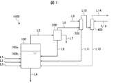
- FIG. 1 is a schematic diagram showing an embodiment of a PAS manufacturing apparatus according to an embodiment of the present invention. The configuration and operation of the above embodiment will be described below with reference to FIG.
- the PAS manufacturing apparatus 1000 includes a polymerization unit 100, a dehydration unit 200, a first recovery unit 300, and a second recovery unit 400.
- the polymerization unit 100 is supplied with an organic polar solvent, a sulfur source, and a dihaloaromatic compound through lines L1 to L3, respectively.
- a gas phase 100 a and a liquid phase 100 b are accommodated in the polymerization unit 100.
- the polymerization unit 100 generates a PAS by polymerizing a sulfur source and a dihaloaromatic compound in an organic polar solvent.
- the reaction mixture containing the PAS, the organic polar solvent, and the alkali metal halide generated in the polymerization unit 100 is recovered through the line L4.
- the gas phase 100a communicates with the dehydrating unit 200 through the line L5.
- the dehydration unit 200 includes a first intermediate gas phase containing dihaloaromatic compound (DH11) and hydrogen sulfide (S1), water, and water by condensation from the gas phase 100a containing water, dihaloaromatic compound, and hydrogen sulfide.
- a dihaloaromatic compound (DH12) and a first intermediate liquid phase containing a sulfur source (S2). Therefore, the dehydrating unit 200 includes at least water, a dihaloaromatic compound, hydrogen sulfide (present in the gas phase), and a sulfur source (present in the liquid phase).
- the first intermediate gas phase is supplied to the first recovery unit 300 through the line L6.
- the first recovery unit 300 is configured to bring the first intermediate gas phase supplied through the line L6 into contact with the organic polar solvent supplied to the first recovery unit 300 through the line L9 to contain hydrogen sulfide (S3).
- a recovered gas phase and a first recovered liquid phase containing an organic polar solvent, a dihaloaromatic compound, and a sulfur source (S4) are generated. Therefore, the first recovery unit 300 includes at least a dihaloaromatic compound, hydrogen sulfide (present in the gas phase), a sulfur source (present in the liquid phase), and an organic polar solvent.
- the first recovery gas phase is supplied to the second recovery unit 400 through the line L10.
- the first recovered liquid phase is supplied to the polymerization unit 100 through the line L11, and the components in the first recovered liquid phase are reused as raw materials for the polymerization reaction.
- the second recovery unit 400 brings the first recovery gas phase supplied through the line L10 into contact with the aqueous alkali metal hydroxide solution supplied to the second recovery unit 400 through the line L12, thereby providing a water and sulfur source (S5). And a second recovered liquid phase containing an alkali metal hydroxide and a waste gas phase containing the remaining hydrogen sulfide. Therefore, the second recovery unit 400 includes at least hydrogen sulfide (present in the gas phase), a sulfur source (present in the liquid phase), water, and an alkali metal hydroxide.
- FIG. 2 is a partial cross-sectional view showing an embodiment (hereinafter, referred to as “Embodiment 1”) of the polymerization section 100 in the case of a PAS continuous production apparatus.
- Embodiment 1 an embodiment of the polymerization section 100 in the case of a PAS continuous production apparatus.
- the PAS continuous production apparatus 101 includes a storage chamber 2 that stores reaction vessels 1a, 1b, and 1c.
- the storage chamber 2 is installed so as to be inclined with respect to the horizontal plane H so as to form an angle ⁇ .
- the shape of the storage chamber 2 is not particularly limited, and examples thereof include a hollow cylindrical shape or a hollow prism shape having a side wall 3a in contact with the reaction vessel 1a and a side wall 3b in contact with the reaction vessel 1c as bottom surfaces.
- One end of the exhaust line 13 is connected to the vicinity of the side wall 3 a of the storage chamber 2.
- the other end of the exhaust line 13 is connected to a dehydrating unit 200 (not shown in FIG. 2) that performs dehydration from the gas phase in the storage chamber 2.
- the dehydrating unit 200 communicates with the gas phase in the storage chamber 2 through the exhaust line 13.
- a mixture supply line 4a (not shown) is connected to the side wall 3a, and the mixture is supplied to the storage chamber 2 through the mixture supply line 4a. Can be supplied.
- the reaction tanks 1a to 1c communicate with each other through the gas phase in the storage chamber 2, and since the pressure of the gas phase in the storage chamber 2 is uniform, any one of the reaction tanks 1a to 1c is performed by the dehydrating unit 200. Therefore, the amount of water in the reaction mixture decreases from the reaction tank 1a toward the reaction tank 1c, that is, from the upstream side to the downstream side in the moving direction of the reaction mixture. As a result, reaction inhibition by water is suppressed and the polymerization reaction is promoted. Moreover, since the boiling point of the reaction mixture increases, polymerization at a high temperature becomes possible, and further the polymerization reaction can be promoted.
- the inert gas is fed into the gas phase in the storage chamber 2 from the downstream side in the moving direction of the reaction mixture toward the upstream side, that is, from the reaction tank 1c toward the reaction tank 1a.
- the water evaporated from the reaction mixture flows to the downstream side. It is preferred not to condense on the reaction mixture.
- the inert gas may not be sent into the gas phase in the storage chamber 2.
- the flow rate of the inert gas is, for example, F >> D ⁇ ⁇ r, more specifically F> 10D ⁇ ⁇ r, preferably F> 25D ⁇ ⁇ r, more preferably F> 50D ⁇ ⁇ r. Range values are listed.
- the storage chamber 2 has a side wall 3a and a side wall 3b as bottom surfaces and a hollow column shape having an arbitrary shape in a cross section perpendicular to the moving direction of the reaction mixture
- a representative example in a direction perpendicular to the moving direction of the reaction mixture is used. It is possible to apply the above formula where r is an equivalent length, for example, an equivalent circle diameter of a cross section having an arbitrary shape.
- the shaft 11 is rotated by the rotation driving device 12, and the stirring blades 10a to 10c installed on the shaft 11 are rotated around the shaft 11, and the reaction mixtures 9a to 9c are stirred.
- the stirring blades 10a to 10c are installed on the same shaft 11. Therefore, only by rotating the shaft 11 by the rotation drive device 12, all of the stirring blades 10a to 10c can be rotated under the same conditions, and homogeneous stirring can be realized with high efficiency.
- alkali metal halide such as NaCl precipitates and accumulates in the reaction vessels 1a to 1c.
- productivity is likely to be lowered.
- a speed that is 5 rmp or less is more preferable.
- the stirring blade preferably passes through at least a portion deeper than the average depth of each of the reaction vessels 1a to 1c.
- the gap between the stirring blade 10a and the bottom of the reaction tank 1a, the stirring blade 10a, and the partition wall 8a are sufficiently stirred around the deepest part of each of the reaction tanks 1a to 1c so that alkali metal halide does not accumulate.
- the PAS continuous production apparatus 101 does not require a plurality of polymerization cans. Therefore, piping between a plurality of polymerization cans, transfer equipment, instrumentation, and the like are unnecessary. Moreover, the driving of the PAS continuous manufacturing apparatus 101 uses the gravity to move the reaction mixture on the basis of the difference in the maximum liquid level, so that a great deal of energy is not required. Therefore, the PAS continuous manufacturing apparatus 101 can easily save resources, save energy, reduce equipment costs, and the like.
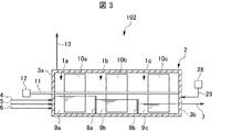
- FIG. 3 is a partial cross-sectional view showing another embodiment (hereinafter referred to as “Embodiment 2”) of the overlapping portion 100 in the case of a PAS continuous production device.
- Embodiment 2 Another embodiment of the overlapping portion 100 in the case of a PAS continuous production device.
- the configuration and operation of the second embodiment will be described below based on FIG.
- the point that the storage chamber 2 is installed horizontally, the height of the partition wall 8a is higher than the height of the partition wall 8b, and the connection position of the reaction mixture recovery line 7 on the side wall 3b are as follows. Except for the differences, this is the same as the PAS continuous production apparatus 101 according to the first embodiment.
- the reaction mixture moves in the order of the reaction tanks 1a, 1b, and 1c, and the PAS continuous production device 102 operates in the same manner as the PAS continuous production device 101.
- the depth of each of the reaction vessels 1a to 1c is almost constant depending on the location. Therefore, it is particularly preferable that the stirring by the stirring blades 10a to 10c is sufficiently performed because the alkali metal halide is likely to accumulate on the entire bottom surface of the reaction tanks 1a to 1c.
- the width of the stirring blades 10a to 10c is preferably wide, for example, 50% of the width of the reaction tanks 1a to 1c. % Or more, preferably 60% or more, more preferably 70% or more, and even more preferably 80% or more. Further, all or a part of the stirring blades 10a to 10c are preferably located at the center of each reaction tank from the viewpoint that a large bias is not easily generated in stirring.
- the stirring shafts described in Embodiments 1 and 2 may be biaxial or multiaxial with three or more axes.
- the partition walls described in Embodiments 1 and 2 may be installed on a stirring shaft.
- PAS continuous manufacturing apparatus of the second embodiment may be configured as described in the following modification.
- a plurality of reaction tanks are arranged adjacent to each other in the vertical direction in the accommodation chamber.
- the reaction tanks adjacent to each other are separated by a partition plate, and the reaction mixture is sequentially moved from the upper reaction tank to the lower reaction tank through the communication pipe.
- each reaction tank communicates with the gas phase portion of each reaction tank through a communication pipe. Therefore, the pressure of the gas phase in each reaction tank in the storage chamber is almost the same.
- the communication pipe communicating with the gas phase portion may be the same as the communication pipe through which the reaction mixture sequentially moves, or may be a communication pipe provided separately.
- the first reaction tank and the second reaction tank communicate with each other through a first communication pipe, and a tube wall of the first communication pipe projects from the first reaction tank side.
- the height of the tube wall of the first communication pipe is set to be equal to the maximum liquid level of the liquid that can be accommodated in the first reaction tank.
- the first communication pipe passes through the first partition plate that separates the first reaction tank and the second reaction tank.
- the reaction mixture when the height of the reaction mixture exceeds the maximum liquid level of the first reaction tank, the reaction mixture exceeds the wall of the first connection pipe and is connected to the first connection pipe. It flows into the pipe and flows into the second reaction tank through the first connecting pipe.
- the reaction mixture may be moved sequentially. While the height of the reaction mixture in the first reaction tank is below the maximum liquid level of the first reaction tank, the first reaction tank and the second reaction tank are connected to the first reaction tank by the communication pipe. And the gas phase part of the second reaction tank communicate with each other.
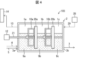
- FIG. 4 is a partial cross-sectional view showing still another embodiment (hereinafter, referred to as “Embodiment 3”) of the polymerization section 100 in the case of a PAS continuous production apparatus.
- Embodiment 3 still another embodiment of the polymerization section 100 in the case of a PAS continuous production apparatus.
- the configuration and operation of the third embodiment will be described below based on FIG.
- the continuous polymerization apparatus 104 is different from the first embodiment in that the isolating means for isolating the reaction tank is not a partition wall but a partition plate having a rotation center in the storage chamber 2.
- reaction tank 1a and the reaction tank 1b are separated by a partition plate 20a, and the reaction tank 1b and the reaction tank 1c are separated by a partition plate 20b.
- the reaction tank 1a, the reaction tank 1b, and the reaction tank 1c are in communication with each other through a gas phase portion in the storage chamber 2.
- a stirring blade 10a for stirring the reaction mixture 9a in the reaction tank 1a is attached to one side of the partition plate 20a.
- a stirring blade 10b for stirring the reaction mixture 9b in the reaction tank 1b is attached to one surface of the partition plate 20b.
- the stirring blades 10a and 10b in this embodiment have a structure in which an opening is provided on the inner side.
- the stirring blades 10a and 10b and the partition plates 20a and 20b are all installed on the same rotating shaft 21.
- the rotating shaft 21 is installed so as to penetrate the side wall 3a from the outside of the storage chamber 2 and reach the side wall 3b.
- a rotary drive device 12 that rotates the rotary shaft 21 is installed at the end of the rotary shaft 21 on the side wall 3a side.
- the stirring blade can be installed at an arbitrary position with respect to the partition plate.
- the partition plate may be on the upstream side of the stirring blade, may be on the downstream side, or these may be mixed.
- the partition plate may be separated from the stirring blade, it is preferable that the partition plate can be fixed and reinforced by being in close contact as shown in FIG.
- the stirring blade and the partition plate do not necessarily need to be a pair, and there may be a place where there is no stirring blade between adjacent partition plates.
- the stirring blade may not be provided, and thereby a simpler apparatus configuration is possible.
- the shape of the partition plate is not particularly limited.
- the partition plate has a center of rotation and a clearance having a predetermined width so that adjacent reaction vessels communicate with each other while partially closing the vertical section in the storage chamber 2.
- any shape that provides an opening for example, when the storage chamber 2 has a hollow cylindrical shape, as shown in FIG. 3, it may be a disk-shaped partition plate having a radius that is slightly smaller than the internal space of the storage chamber.
- the shape of a partition plate is not limited to this, A cage
- the number of partition plates provided on the rotating shaft may be an arbitrary number of 1 or more depending on the size of the storage chamber and the type of polymerization reaction.
- each partition plate is not particularly limited, and can be provided at an arbitrary position.
- the shape of the stirring blade is not particularly limited, and may be any shape that is provided coaxially with the partition plate and stirs the reaction mixture.
- the stirring blade 10 may be attached to any one surface of the partition plate 20, or may be attached to both surfaces.
- the rotating shaft 21 may be attached separately from the partition plate.
- the liquid phase portions communicate with each other.
- the raw material and solvent supplied to the reaction tank 1a sequentially move to the reaction tanks 1b and 1c while a polymerization reaction proceeds as a reaction mixture.
- reaction tanks 1a to 1c are in communication with each other in the gas phase. As a result, the pressure of the gas phase in the storage chamber 2 becomes uniform.
- the evaporation components generated during the polymerization in each reaction tank are sequentially moved from the reaction tank 1c to the directions 1b and 1a through the gas phase due to a temperature difference in the apparatus, and the like. Discharged.
- a clearance having a predetermined width exists between the inner wall of the storage chamber 2 and the outer edges of the partition plates 20a to 20b.
- the gas phase portions and the liquid phase portions of the adjacent reaction tanks communicate with each other, and the reaction mixture, the gas containing the evaporation component, and the like move.
- an opening such as a through hole or a slit may be provided in the partition plate, and the reaction tank may be communicated with the opening.
- the partition plate may have a mesh shape having a plurality of fine through holes.
- the width of the clearance or the size of the opening is not particularly limited, and can be appropriately set according to the shape of the container, the shape and number of the partition plates, and the like.
- FIG. 5 is a partial cross-sectional view showing still another embodiment (hereinafter referred to as “Embodiment 4”) of the polymerization section 100 in the case of a PAS continuous production device.
- Embodiment 4 the fourth embodiment of the fourth embodiment will be described below based on FIG.
- the continuous production apparatus 104 includes a first reaction tank 50, a second reaction tank 51, and a third reaction tank 52.
- the second reaction tank 51 is disposed below the first reaction tank 50
- the third reaction tank 52 is disposed below the second reaction tank 51 in the vertical direction.
- the first reaction tank 50 and the second reaction tank 51 are connected by a first pipe 65.
- the second reaction tank 51 and the third reaction tank 52 are connected by a second pipe 67.
- the reaction raw material is supplied to the first reaction tank 50.
- the polymerization solvent and the reaction raw material are supplied from the organic polar solvent supply line 4 to the first reaction tank 50, and the first pipe 65 is used when the reaction mixture in the first reaction tank 50 exceeds the maximum liquid level.
- the reaction mixture is provided so as to move to the second reaction tank 51 through the first pipe 65.
- the second pipe 67 moves to the third reaction tank 52 through the second pipe 67 when the reaction mixture in the second reaction tank 51 exceeds the maximum liquid level. It is provided as follows. And it collect
- a vent 70 is connected to each of the first to third reaction vessels 50 to 52.
- the first to third reaction tanks 50 to 52 are communicated with each other via a gas phase via the aeration unit 70.
- Embodiment 1 Even if the reaction mixture is sequentially moved by using the difference in the maximum liquid level between the first reaction tank 50 and the second reaction tank 51 by the configuration of the continuous production apparatus 104 as described above, Embodiment 1 The same effect can be obtained. Furthermore, according to the continuous manufacturing machine 104, it is not necessary to provide a partition wall as shown in the first embodiment.
- a method for producing a PAS includes a gas phase containing water, a dihaloaromatic compound, and hydrogen sulfide, and a liquid phase containing an organic polar solvent and PAS.
- a condensation step to obtain a first intermediate gas phase containing a dihaloaromatic compound and hydrogen sulfide and a first intermediate liquid phase containing water, a dihaloaromatic compound and a sulfur source by condensation from the gas phase;
- the first intermediate gas phase is brought into contact with an organic polar solvent, a first recovery gas phase containing hydrogen sulfide, and a first recovery liquid phase containing an organic polar solvent, a dihaloaromatic compound, and a sulfur source.
- a method for producing a PAS according to an embodiment of the present invention while evaporating water from a liquid phase of a reaction system containing an organic polar solvent, water, a sulfur source, and a dihaloaromatic compound to the gas phase of the reaction system, It is preferable that a polymerization step of polymerizing a sulfur source and a dihaloaromatic compound in an organic polar solvent to produce PAS to obtain the gas-liquid system is further included before the condensation step.
- the method for producing a PAS it is preferable to use at least a part of the dihaloaromatic compound in the first recovery liquid phase as at least a part of the dihaloaromatic compound in the polymerization step.
- the organic polar solvent in the first recovered liquid phase and the organic polar solvent in the polymerization step are preferably the same type.
- Operation 1 Continuous raw material supply operation for continuously supplying an organic polar solvent, a sulfur source, and a dihaloaromatic compound
- Operation 2 Continuous dehydration operation for continuously discharging water in the reaction system out of the reaction system
- Operation 3 Continuous polymerization operation in which a sulfur source and a dihaloaromatic compound are continuously polymerized in an organic polar solvent
- Operation 4 Pressure adjustment operation for adjusting the pressure in the reaction system by continuously discharging non-condensable gas in the reaction system to the outside of the reaction system
- Operation 5 Continuously producing the generated reaction mixture Continuous collection operation to collect, Are preferably performed in parallel to continuously generate PAS.
- An apparatus for producing a PAS according to the present invention includes a gas phase containing water, a dihaloaromatic compound, and hydrogen sulfide, and a liquid phase containing an organic polar solvent and PAS.
- a dehydration unit that produces a first intermediate gas phase containing a dihaloaromatic compound and hydrogen sulfide and a first intermediate liquid phase containing water, a dihaloaromatic compound, and a sulfur source by condensation;
- the first intermediate gas phase is brought into contact with an organic polar solvent, a first recovery gas phase containing hydrogen sulfide, and a first recovery liquid phase containing an organic polar solvent, a dihaloaromatic compound, and a sulfur source.
- the apparatus for producing a PAS evaporates water from a liquid phase of a reaction system containing an organic polar solvent, water, a sulfur source, and a dihaloaromatic compound to the gas phase of the reaction system, It further comprises a polymerization part for polymerizing a sulfur source and a dihaloaromatic compound in an organic polar solvent to produce PAS, thereby producing the gas-liquid system.
- Example 1 The PAS manufacturing apparatus shown in FIG. 1 was used. As the superposition
- the temperature 1 of the part partitioned by the first partition and the second partition from the upstream side is divided at 230 ° C, the third partition and the fourth partition
- the raw material was continuously supplied at a flow rate of 0.84 g / min.
- the dehydrating unit 200 as a distillation apparatus connected to the PAS continuous production device, water was continuously removed from the PAS continuous production device while controlling the pressure to a gauge pressure of 0.32 MPa by a pressure regulating valve. Furthermore, the removed pDCB in water was separated in a stationary tank constituting a part of the dewatering unit 200 and returned to the PAS continuous production apparatus. Of the first intermediate liquid phase, water and sulfur source were discarded through line L7. The gas from the dehydration unit 200 was passed through the first recovery unit 300, which is a packed tower, and contacted with NMP having a flow rate of 0.5 g / min in a countercurrent. The liquid phase from the first recovery unit 300 was returned to the PAS continuous production device.
- recovery part 300 led to the 2nd collection
- the liquid phase from the second recovery unit 400 was returned to the PAS continuous production machine.
- the gas from the second recovery unit 400 was exhausted through a line L14 after passing through 5 kg of 5% by weight sodium hydroxide aqueous solution and completely absorbing and recovering hydrogen sulfide.
- the polymerization reaction product was continuously discharged from the continuous production apparatus of PAS and cooled.
Landscapes
- Chemical & Material Sciences (AREA)
- Health & Medical Sciences (AREA)
- Chemical Kinetics & Catalysis (AREA)
- Medicinal Chemistry (AREA)
- Polymers & Plastics (AREA)
- Organic Chemistry (AREA)
- General Chemical & Material Sciences (AREA)
- Polymers With Sulfur, Phosphorus Or Metals In The Main Chain (AREA)
Abstract
Description
前記第1中間気相を有機極性溶媒と接触させて、硫化水素を含有する第1回収気相と、有機極性溶媒、ジハロ芳香族化合物、及び硫黄源を含有する第1回収液相と、を得る第1回収工程と、
前記第1回収気相をアルカリ金属水酸化物水溶液と接触させて、水、硫黄源、及びアルカリ金属水酸化物を含有する第2回収液相を得る第2回収工程と、
を含む。
前記第1中間気相を有機極性溶媒と接触させて、硫化水素を含有する第1回収気相と、有機極性溶媒、ジハロ芳香族化合物、及び硫黄源を含有する第1回収液相と、を生成する第1回収部と、
前記第1回収気相をアルカリ金属水酸化物水溶液と接触させて、水、硫黄源、及びアルカリ金属水酸化物を含有する第2回収液相を生成する第2回収部と、
を備える。
本発明の一実施形態に係るPASの製造方法は、水、ジハロ芳香族化合物、及び硫化水素を含有する気相と、有機極性溶媒及びPASを含有する液相と、を含む気液系における前記気相からの凝縮により、ジハロ芳香族化合物及び硫化水素を含有する第1中間気相と、水、ジハロ芳香族化合物、及び硫黄源を含有する第1中間液相と、を得る凝縮工程と、
前記第1中間気相を有機極性溶媒と接触させて、硫化水素を含有する第1回収気相と、有機極性溶媒、ジハロ芳香族化合物、及び硫黄源を含有する第1回収液相と、を得る第1回収工程と、
前記第1回収気相をアルカリ金属水酸化物水溶液と接触させて、水、硫黄源、及びアルカリ金属水酸化物を含有する第2回収液相を得る第2回収工程と、
を含む。本発明の一実施形態に係るPASの製造方法によれば、前記気液系における前記気相からの脱水時に揮散し得るジハロ芳香族化合物及び硫化水素を効果的に回収することができる。
凝縮工程では、水、ジハロ芳香族化合物、及び硫化水素を含有する気相と、有機極性溶媒及びPASを含有する液相と、を含む気液系における前記気相からの凝縮により、ジハロ芳香族化合物及び硫化水素を含有する第1中間気相と、水、ジハロ芳香族化合物、及び硫黄源を含有する第1中間液相と、を得る。上記凝縮工程により、上記気液系における上記気相から十分に脱水を行うことができる。それに伴い、ジハロ芳香族化合物は、主に上記第1中間液相に偏在し、硫化水素は、主に上記第1中間気相に偏在する。
第1回収工程では、前記第1中間気相を有機極性溶媒と接触させて、硫化水素を含有する第1回収気相と、有機極性溶媒、ジハロ芳香族化合物、及び硫黄源を含有する第1回収液相と、を得る。上記第1回収工程により、上記第1中間気相から、主にジハロ芳香族化合物を、第1回収液相中に十分に回収することができる。また、上記第1回収工程により、上記第1中間気相から、硫化水素の一部を第1回収液相中に回収することもできる。
第2回収工程では、前記第1回収気相をアルカリ金属水酸化物水溶液と接触させて、水、硫黄源、及びアルカリ金属水酸化物を含有する第2回収液相を得る。上記第2回収工程により、上記第1回収気相から硫化水素を第2回収液相中に十分に回収することができる。アルカリ金属水酸化物水溶液の濃度は、特に制限ないが、硫化水素を十分に回収できる濃度であることが好ましくより好ましくは5~80質量%、さらに好ましくは10~77質量%である。なお、前記第1回収気相中の硫化水素は、アルカリ金属水酸化物水溶液中のアルカリ金属水酸化物と反応して、アルカリ金属硫化物及びアルカリ金属水硫化物を生成し得る。よって、第2回収液相は、アルカリ金属硫化物、アルカリ金属水硫化物、硫化水素等の硫黄源を含有する。なお、当該アルカリ金属水酸化物水溶液は有機極性溶媒を含んでいてもよい。
本発明の一実施形態に係るPASの製造方法は、有機極性溶媒、水、硫黄源、及びジハロ芳香族化合物を含有する反応系の液相から前記反応系の気相へ水を蒸発させつつ、有機極性溶媒中で硫黄源とジハロ芳香族化合物とを重合させてPASを生成させて、前記気液系を得る重合工程を、前記凝縮工程の前に更に含んでもよい。有機極性溶媒、硫黄源、及びジハロ芳香族化合物としては、PASの製造において通常用いられるものを用いることができる。
有機極性溶媒、硫黄源、及びジハロ芳香族化合物の供給と、
有機極性溶媒中での硫黄源とジハロ芳香族化合物との重合によるPASの生成と、
前記PASを含む反応混合物の回収と、
を同時並行で行うことにより、上記重合反応を連続的に行うことができる。
操作1:有機極性溶媒、硫黄源、及びジハロ芳香族化合物を連続的に供給する連続原料供給操作、
操作2:前記反応系内の水を前記反応系外に連続的に排出する連続脱水操作、
操作3:有機極性溶媒中で硫黄源とジハロ芳香族化合物とを連続的に重合させる連続重合操作、
操作4:前記反応系内の非凝縮性気体を前記反応系外に連続的に排出することにより前記反応系内の圧力を調整する圧力調整操作、並びに
操作5:生成した反応混合物を連続的に回収する連続回収操作、
を同時並行で行い、PASを連続的に生成させることが好ましい。
複数の反応槽を収容する収容室を備え、前記反応槽が直列に接続されるPASの製造装置内の前記収容室に、少なくとも、有機極性溶媒、アルカリ金属硫化物、アルカリ金属水硫化物、及び硫化水素からなる群より選ばれる少なくとも一種の硫黄源、並びにジハロ芳香族化合物を供給する工程と、
各反応槽において、前記有機極性溶媒中で、前記硫黄源と前記ジハロ芳香族化合物との重合反応を行うことにより、反応混合物を形成する工程と、
前記収容室内の水の少なくとも一部を、前記収容室における気相を介して、前記収容室から除去する工程と、
各反応槽に、前記反応混合物を順次移動させる工程と、
を同時並行で行い、PASを連続的に生成させることが好ましい。前記反応槽は、各反応槽が収容し得る液体の最大液面レベルの高い順番で直列に接続され、前記最大液面レベルの高低差により、前記順番に従って、前記最大液面レベルのより高い反応槽から前記最大液面レベルのより低い反応槽に、前記反応混合物を順次移動させることが好ましい。前記反応混合物の移動方向の下流側から上流側に向けて、前記気相に不活性ガスを送り込む工程を更に同時並行で行うことがより好ましい。このようにしてPASを連続的に生成させる重合工程は、後述の実施形態1及び2として開示するPAS連続製造器により行うことができる。
本発明の一実施形態に係るPASの製造装置は、水、ジハロ芳香族化合物、及び硫化水素を含有する気相と、有機極性溶媒及びポリアリーレンスルフィドを含有する液相と、を含む気液系における前記気相からの凝縮により、ジハロ芳香族化合物及び硫化水素を含有する第1中間気相と、水、ジハロ芳香族化合物、及び硫黄源を含有する第1中間液相と、を生成する脱水部と、
前記第1中間気相を有機極性溶媒と接触させて、硫化水素を含有する第1回収気相と、有機極性溶媒、ジハロ芳香族化合物、及び硫黄源を含有する第1回収液相と、を生成する第1回収部と、
前記第1回収気相をアルカリ金属水酸化物水溶液と接触させて、水、硫黄源、及びアルカリ金属水酸化物を含有する第2回収液相を生成する第2回収部と、
を備える。本発明に係るPASの製造装置によれば、前記気液系における前記気相からの脱水時に揮散し得るジハロ芳香族化合物及び硫化水素を効果的に回収することができる。
図2は、PAS連続製造器である場合の重合部100の一実施形態(以下、「実施形態1」という。)を示す部分断面図である。以下、図2に基づき、実施形態1の構成を説明する。
図3は、PAS連続製造器である場合の重合部100の別の実施形態(以下、「実施形態2」という。)を示す部分断面図である。以下、図3に基づき、実施形態2の構成及び動作を説明する。
変形例に係るPAS連続製造器(図示せず)は、収容室内において、複数の反応槽が鉛直方向に隣接して配置されている。互いに隣接する反応槽は仕切り板によって隔たれているとともに、連通管を通して上側の反応槽から下側の反応槽へと反応混合物が順次移動さするように構成されている。また各反応槽は連通管により、各反応槽の気相部が互いに連通している。そのため収容室における各反応槽の気相の圧力はほぼ同一である。気相部を連通する連通管は、反応混合物が順次移動する連通管と同一であってもよいし、別に設けた連通管であってもよい。ここで、鉛直方向上側から順に第1の反応槽と、第2の反応槽が設けられている場合を例にして具体的に説明する。第1の反応槽と第2の反応槽とは第1の連通管を通じて連通しており、第1の反応槽側には、第1の連通管の管壁が突出している。第1の連通管の管壁の高さは、第1の反応槽が収容し得る液体の最大液面レベルと等しくなるように設けられている。第1の連通管は、第1の反応槽と第2の反応槽とを隔てる第1の仕切り板を貫通している。
図4は、PAS連続製造器である場合の重合部100のさらに別の実施形態(以下、「実施形態3」という。)を示す部分断面図である。以下、図4に基づき、実施形態3の構成及び動作を説明する。
図5は、PAS連続製造器である場合の重合部100のさらに別の実施形態(以下、「実施形態4」という。)を示す部分断面図である。以下、図5に基づき、実施形態4の構成及び動作を説明する。
本発明の一実施形態に係るPASの製造方法は、水、ジハロ芳香族化合物、及び硫化水素を含有する気相と、有機極性溶媒及びPASを含有する液相と、を含む気液系における前記気相からの凝縮により、ジハロ芳香族化合物及び硫化水素を含有する第1中間気相と、水、ジハロ芳香族化合物、及び硫黄源を含有する第1中間液相と、を得る凝縮工程と、
前記第1中間気相を有機極性溶媒と接触させて、硫化水素を含有する第1回収気相と、有機極性溶媒、ジハロ芳香族化合物、及び硫黄源を含有する第1回収液相と、を得る第1回収工程と、
前記第1回収気相をアルカリ金属水酸化物水溶液と接触させて、水、硫黄源、及びアルカリ金属水酸化物を含有する第2回収液相を得る第2回収工程と、
を含む。
操作1:有機極性溶媒、硫黄源、及びジハロ芳香族化合物を連続的に供給する連続原料供給操作、
操作2:前記反応系内の水を前記反応系外に連続的に排出する連続脱水操作、
操作3:有機極性溶媒中で硫黄源とジハロ芳香族化合物とを連続的に重合させる連続重合操作、
操作4:前記反応系内の非凝縮性気体を前記反応系外に連続的に排出することにより前記反応系内の圧力を調整する圧力調整操作、並びに
操作5:生成した反応混合物を連続的に回収する連続回収操作、
を同時並行で行い、PASを連続的に生成させることが好ましい。
前記第1中間気相を有機極性溶媒と接触させて、硫化水素を含有する第1回収気相と、有機極性溶媒、ジハロ芳香族化合物、及び硫黄源を含有する第1回収液相と、を生成する第1回収部と、
前記第1回収気相をアルカリ金属水酸化物水溶液と接触させて、水、硫黄源、及びアルカリ金属水酸化物を含有する第2回収液相を生成する第2回収部と、
を備える。
図1に示すPASの製造装置を用いた。重合部100としては、収容室2が5枚の隔壁により仕切られて形成された6個の反応槽を有する以外は、図2に示すのと同様のPAS連続製造器を用いた。このPAS連続製造器は、隔壁が半円形状であり、直径100mm×300mmの寸法を有するTi製反応装置であった。上記PAS連続製造器に、NMP950gを仕込んだ後、上流側から1番目の隔壁と2番目の隔壁とで区切られた部分の温度1を230℃、3番目の隔壁と4番目の隔壁とで区切られた部分の温度2を260℃に保持し、各供給ラインより定量ポンプを用いてNMP-pDCB混合液3.52g/min(NMP:pDCB(質量比)=990:278)、36質量%NaSH水溶液0.84g/minの流量にて連続的に原料を供給した。同時にPAS連続製造器に接続された蒸留装置として脱水部200を用いて、圧力調整弁によって圧力をゲージ圧0.32MPaに制御しながら、PAS連続製造器より連続的に水を除去した。更に、除去した水中のpDCBについては、脱水部200の一部を構成する静置槽で分離してPAS連続製造器に戻した。第1中間液相のうち、水及び硫黄源はラインL7を通して廃棄した。脱水部200からのガスは、充填塔である第1回収部300に通じ、向流で0.5g/minの流量のNMPと接触させた。第1回収部300からの液相は、PAS連続製造器に戻した。一方、第1回収部300からのガスは、充填塔である第2回収部400に通じ、向流で1.37g/minの流量の15.84質量%水酸化ナトリウム水溶液と接触させた。第2回収部400からの液相は、PAS連続製造器に戻した。一方、第2回収部400からのガスは、5質量%の水酸化ナトリウム水溶液5kgに通じて硫化水素を完全に吸収・回収した後に、ラインL14を通じて排気した。重合反応物はPAS連続製造器から連続的に溢流させて抜出し、冷却した。

操作時間を5時間から2時間に変更し、NMP-pDCB混合液の流量及び組成をそれぞれ3.54g/min及びNMP:pDCB(質量比)=988:286に変更した以外は、実施例1と同様にして、硫黄についてマテリアルバランスを調べた。結果を表2に示す。
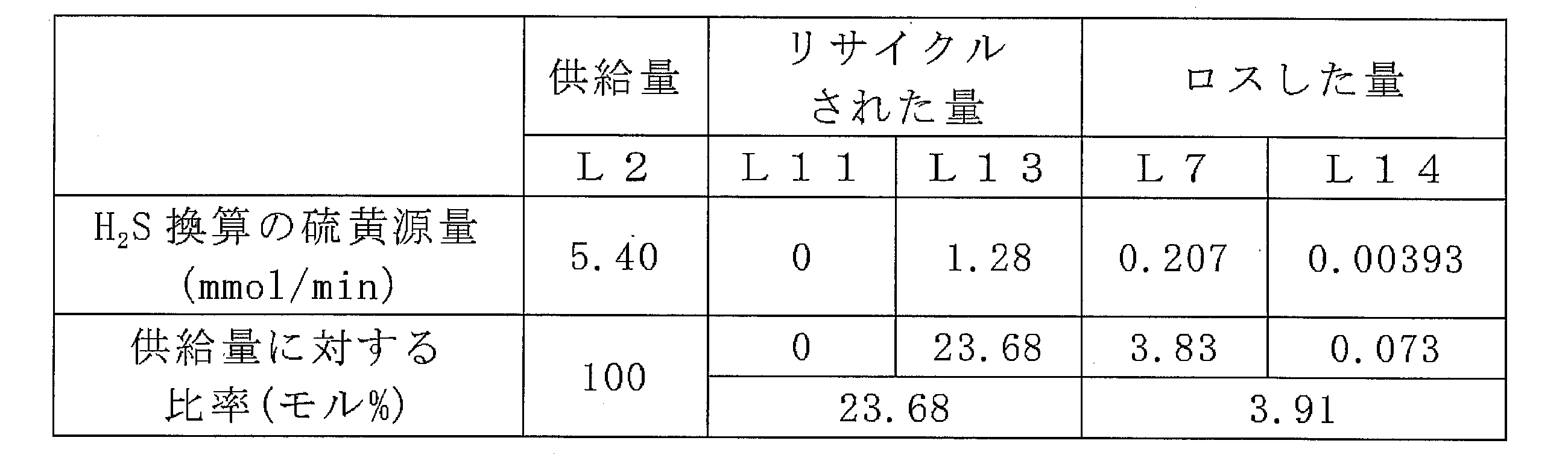
操作時間を5時間から7時間に変更し、NMP-pDCB混合液の流量及び組成をそれぞれ3.55g/min及びNMP:pDCB(質量比)=986:294に変更し、15.84質量%水酸化ナトリウム水溶液の流量を1.36g/minに変更した以外は、実施例1と同様にして、硫黄についてマテリアルバランスを調べた。結果を表3に示す。
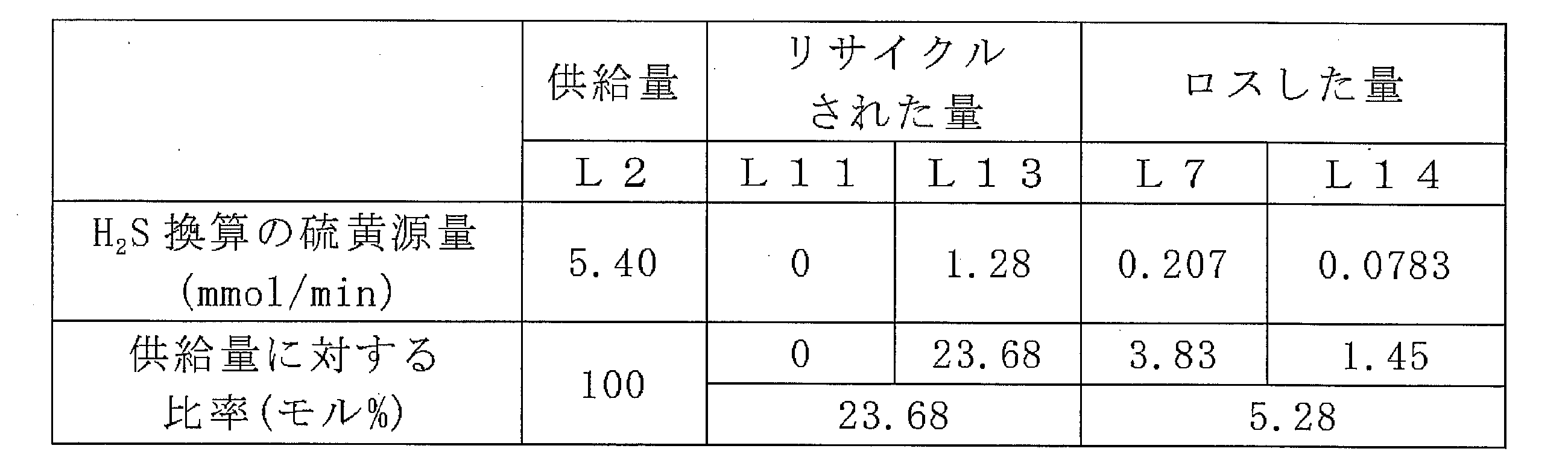
操作時間を5時間から7時間に変更し、第1回収部300及び第2回収部400を用いず、第2回収部400からのガスの代わりに脱水部200からのガスを用いた以外は、実施例1と同様にして、硫黄についてマテリアルバランスを調べた。結果を表4に示す。

Claims (11)
- 水、ジハロ芳香族化合物、及び硫化水素を含有する気相と、有機極性溶媒及びポリアリーレンスルフィドを含有する液相と、を含む気液系における前記気相からの凝縮により、ジハロ芳香族化合物及び硫化水素を含有する第1中間気相と、水、ジハロ芳香族化合物、及び硫黄源を含有する第1中間液相と、を得る凝縮工程と、
前記第1中間気相を有機極性溶媒と接触させて、硫化水素を含有する第1回収気相と、有機極性溶媒、ジハロ芳香族化合物、及び硫黄源を含有する第1回収液相と、を得る第1回収工程と、
前記第1回収気相をアルカリ金属水酸化物水溶液と接触させて、水、硫黄源、及びアルカリ金属水酸化物を含有する第2回収液相を得る第2回収工程と、
を含む、ポリアリーレンスルフィドの製造方法。 - 有機極性溶媒、水、硫黄源、及びジハロ芳香族化合物を含有する反応系の液相から前記反応系の気相へ水を蒸発させつつ、有機極性溶媒中で硫黄源とジハロ芳香族化合物とを重合させてポリアリーレンスルフィドを生成させて、前記気液系を得る重合工程を、前記凝縮工程の前に更に含む請求項1に記載の方法。
- 前記第1回収液相中のジハロ芳香族化合物の少なくとも一部を、前記重合工程におけるジハロ芳香族化合物の少なくとも一部として用いる請求項2に記載の方法。
- 前記第1回収液相中の硫黄源の少なくとも一部を、前記重合工程における硫黄源の少なくとも一部として用いる請求項2又は3に記載の方法。
- 前記第1回収液相中の有機極性溶媒と前記重合工程における有機極性溶媒とが同じ種類である請求項3又は4に記載の方法。
- 前記第2回収液相中の硫黄源の少なくとも一部を、前記重合工程における硫黄源の少なくとも一部として用いる請求項2から5のいずれか1項に記載の方法。
- 前記重合工程においては、
操作1:有機極性溶媒、硫黄源、及びジハロ芳香族化合物を連続的に供給する連続原料供給操作、
操作2:前記反応系内の水を前記反応系外に連続的に排出する連続脱水操作、
操作3:有機極性溶媒中で硫黄源とジハロ芳香族化合物とを連続的に重合させる連続重合操作、
操作4:前記反応系内の非凝縮性気体を前記反応系外に連続的に排出することにより前記反応系内の圧力を調整する圧力調整操作、並びに
操作5:生成した反応混合物を連続的に回収する連続回収操作、
を同時並行で行い、ポリアリーレンスルフィドを連続的に生成させる請求項2から6のいずれか1項に記載の方法。 - 前記第1中間液相中の硫化水素の少なくとも一部を、(1)前記第2回収工程において用いる前記アルカリ金属水酸化物水溶液に予め吸収させ、(2)前記第2回収工程において、前記第1回収気相とともに、アルカリ金属水酸化物水溶液と接触させ、及び/又は、(3)前記第2回収液相に吸収させる請求項1から7のいずれか1項に記載の方法。
- 前記第1中間液相中のジハロ芳香族化合物の少なくとも一部を、前記重合工程におけるジハロ芳香族化合物の少なくとも一部として用いる請求項2から7のいずれか1項に記載の方法。
- 水、ジハロ芳香族化合物、及び硫化水素を含有する気相と、有機極性溶媒及びポリアリーレンスルフィドを含有する液相と、を含む気液系における前記気相からの凝縮により、ジハロ芳香族化合物及び硫化水素を含有する第1中間気相と、水、ジハロ芳香族化合物、及び硫黄源を含有する第1中間液相と、を生成する脱水部と、
前記第1中間気相を有機極性溶媒と接触させて、硫化水素を含有する第1回収気相と、有機極性溶媒、ジハロ芳香族化合物、及び硫黄源を含有する第1回収液相と、を生成する第1回収部と、
前記第1回収気相をアルカリ金属水酸化物水溶液と接触させて、水、硫黄源、及びアルカリ金属水酸化物を含有する第2回収液相を生成する第2回収部と、
を備える、ポリアリーレンスルフィドの製造装置。 - 有機極性溶媒、水、硫黄源、及びジハロ芳香族化合物を含有する反応系の液相から前記反応系の気相へ水を蒸発させつつ、有機極性溶媒中で硫黄源とジハロ芳香族化合物とを重合させてポリアリーレンスルフィドを生成させて、前記気液系を生成する重合部を更に備える請求項10に記載の装置。
Priority Applications (4)
| Application Number | Priority Date | Filing Date | Title |
|---|---|---|---|
| KR1020187029135A KR101945017B1 (ko) | 2017-01-18 | 2018-01-11 | 폴리아릴렌 설파이드의 제조 방법 및 폴리아릴렌 설파이드의 제조 장치 |
| US16/096,837 US10604630B2 (en) | 2017-01-18 | 2018-01-11 | Polyarylene sulfide production method and polyarylene sulfide production apparatus |
| JP2018544946A JP6438180B1 (ja) | 2017-01-18 | 2018-01-11 | ポリアリーレンスルフィドの製造方法及びポリアリーレンスルフィドの製造装置 |
| CN201880001618.6A CN109071815B (zh) | 2017-01-18 | 2018-01-11 | 聚亚芳基硫醚的制造方法以及聚亚芳基硫醚的制造装置 |
Applications Claiming Priority (2)
| Application Number | Priority Date | Filing Date | Title |
|---|---|---|---|
| JP2017-006747 | 2017-01-18 | ||
| JP2017006747 | 2017-01-18 |
Publications (1)
| Publication Number | Publication Date |
|---|---|
| WO2018135372A1 true WO2018135372A1 (ja) | 2018-07-26 |
Family
ID=62908027
Family Applications (1)
| Application Number | Title | Priority Date | Filing Date |
|---|---|---|---|
| PCT/JP2018/000477 Ceased WO2018135372A1 (ja) | 2017-01-18 | 2018-01-11 | ポリアリーレンスルフィドの製造方法及びポリアリーレンスルフィドの製造装置 |
Country Status (5)
| Country | Link |
|---|---|
| US (1) | US10604630B2 (ja) |
| JP (1) | JP6438180B1 (ja) |
| KR (1) | KR101945017B1 (ja) |
| CN (1) | CN109071815B (ja) |
| WO (1) | WO2018135372A1 (ja) |
Cited By (3)
| Publication number | Priority date | Publication date | Assignee | Title |
|---|---|---|---|---|
| WO2020026590A1 (ja) * | 2018-07-31 | 2020-02-06 | 株式会社クレハ | ポリアリーレンスルフィドの製造方法 |
| WO2020044819A1 (ja) * | 2018-08-29 | 2020-03-05 | 株式会社クレハ | 連続脱水方法およびポリアリーレンスルフィドの製造方法 |
| JPWO2021005839A1 (ja) * | 2019-07-09 | 2021-01-14 |
Families Citing this family (2)
| Publication number | Priority date | Publication date | Assignee | Title |
|---|---|---|---|---|
| KR102499842B1 (ko) * | 2018-12-07 | 2023-02-13 | 주식회사 엘지화학 | 폴리아릴렌 설파이드의 제조 방법 |
| CN113667122A (zh) * | 2021-07-20 | 2021-11-19 | 山东明化新材料有限公司 | 聚芳硫醚树脂的梯度控温连续缩合方法 |
Citations (7)
| Publication number | Priority date | Publication date | Assignee | Title |
|---|---|---|---|---|
| JPH02160833A (ja) * | 1988-12-14 | 1990-06-20 | Toray Philips Petorooriamu Kk | ポリアリーレンスルフィドの製造方法 |
| JPH09286861A (ja) * | 1996-02-21 | 1997-11-04 | Kureha Chem Ind Co Ltd | ポリアリーレンスルフィドの製造方法 |
| JPH107798A (ja) * | 1996-06-27 | 1998-01-13 | Dainippon Ink & Chem Inc | ポリアリーレンスルフィドの製造方法 |
| JPH10158399A (ja) * | 1996-11-29 | 1998-06-16 | Dainippon Ink & Chem Inc | ポリアリーレンスルフィドの製造方法 |
| JP2015218214A (ja) * | 2014-05-15 | 2015-12-07 | Dic株式会社 | スルフィド化剤およびポリアリーレンスルフィド樹脂の製造方法 |
| JP2016536377A (ja) * | 2013-09-25 | 2016-11-24 | ティコナ・エルエルシー | ポリアリーレンスルフィドを形成するためのスクラビングプロセス |
| JP2017043748A (ja) * | 2015-08-28 | 2017-03-02 | Dic株式会社 | ポリアリーレンスルフィド樹脂の製造方法 |
Family Cites Families (9)
| Publication number | Priority date | Publication date | Assignee | Title |
|---|---|---|---|---|
| US5840830A (en) | 1996-02-21 | 1998-11-24 | Kureha Kagaku Kogyo K.K. | Process for producing poly(arylene sulfide) |
| ATE420914T1 (de) * | 2002-12-27 | 2009-01-15 | Kureha Corp | Verfahren zur herstellung von polyarylensulfid |
| JP5361295B2 (ja) | 2008-09-05 | 2013-12-04 | ユニキャリア株式会社 | バッテリ式作業車両の表示装置 |
| CN102224187A (zh) | 2008-11-21 | 2011-10-19 | Dic株式会社 | 聚芳硫醚树脂的制造方法 |
| JP2010144085A (ja) * | 2008-12-19 | 2010-07-01 | Tosoh Corp | ポリフェニレンスルフィドの製造方法 |
| CN103134133B (zh) | 2013-03-08 | 2015-06-24 | 锦州鹏翔电力轻钢设备有限公司 | 薄型屋顶通风器 |
| JP2016536376A (ja) * | 2013-09-25 | 2016-11-24 | ティコナ・エルエルシー | 低ハロゲン含量のポリアリーレンスルフィドを形成する方法 |
| KR101758039B1 (ko) | 2014-03-31 | 2017-07-13 | 가부시끼가이샤 구레하 | 폴리아릴렌 설파이드의 제조방법 |
| WO2015166838A1 (ja) | 2014-04-30 | 2015-11-05 | 株式会社クレハ | ポリアリーレンスルフィドの製造方法、及び、ポリアリーレンスルフィドの製造装置 |
-
2018
- 2018-01-11 CN CN201880001618.6A patent/CN109071815B/zh active Active
- 2018-01-11 JP JP2018544946A patent/JP6438180B1/ja active Active
- 2018-01-11 US US16/096,837 patent/US10604630B2/en active Active
- 2018-01-11 KR KR1020187029135A patent/KR101945017B1/ko not_active Expired - Fee Related
- 2018-01-11 WO PCT/JP2018/000477 patent/WO2018135372A1/ja not_active Ceased
Patent Citations (7)
| Publication number | Priority date | Publication date | Assignee | Title |
|---|---|---|---|---|
| JPH02160833A (ja) * | 1988-12-14 | 1990-06-20 | Toray Philips Petorooriamu Kk | ポリアリーレンスルフィドの製造方法 |
| JPH09286861A (ja) * | 1996-02-21 | 1997-11-04 | Kureha Chem Ind Co Ltd | ポリアリーレンスルフィドの製造方法 |
| JPH107798A (ja) * | 1996-06-27 | 1998-01-13 | Dainippon Ink & Chem Inc | ポリアリーレンスルフィドの製造方法 |
| JPH10158399A (ja) * | 1996-11-29 | 1998-06-16 | Dainippon Ink & Chem Inc | ポリアリーレンスルフィドの製造方法 |
| JP2016536377A (ja) * | 2013-09-25 | 2016-11-24 | ティコナ・エルエルシー | ポリアリーレンスルフィドを形成するためのスクラビングプロセス |
| JP2015218214A (ja) * | 2014-05-15 | 2015-12-07 | Dic株式会社 | スルフィド化剤およびポリアリーレンスルフィド樹脂の製造方法 |
| JP2017043748A (ja) * | 2015-08-28 | 2017-03-02 | Dic株式会社 | ポリアリーレンスルフィド樹脂の製造方法 |
Cited By (15)
| Publication number | Priority date | Publication date | Assignee | Title |
|---|---|---|---|---|
| CN112334514A (zh) * | 2018-07-31 | 2021-02-05 | 株式会社吴羽 | 聚亚芳基硫醚的制造方法 |
| WO2020026590A1 (ja) * | 2018-07-31 | 2020-02-06 | 株式会社クレハ | ポリアリーレンスルフィドの製造方法 |
| JPWO2020026590A1 (ja) * | 2018-07-31 | 2021-02-18 | 株式会社クレハ | ポリアリーレンスルフィドの製造方法 |
| KR102289068B1 (ko) | 2018-08-29 | 2021-08-11 | 가부시끼가이샤 구레하 | 연속 탈수 방법 및 폴리아릴렌 설파이드의 제조방법 |
| JPWO2020044819A1 (ja) * | 2018-08-29 | 2020-12-17 | 株式会社クレハ | 連続脱水方法およびポリアリーレンスルフィドの製造方法 |
| CN112513143A (zh) * | 2018-08-29 | 2021-03-16 | 株式会社吴羽 | 连续脱水方法以及聚亚芳基硫醚的制造方法 |
| KR20210041084A (ko) * | 2018-08-29 | 2021-04-14 | 가부시끼가이샤 구레하 | 연속 탈수 방법 및 폴리아릴렌 설파이드의 제조방법 |
| WO2020044819A1 (ja) * | 2018-08-29 | 2020-03-05 | 株式会社クレハ | 連続脱水方法およびポリアリーレンスルフィドの製造方法 |
| US11155682B2 (en) | 2018-08-29 | 2021-10-26 | Kureha Corporation | Continuous dehydration method and method for producing polyarylene sulfide |
| WO2021005839A1 (ja) * | 2019-07-09 | 2021-01-14 | 株式会社クレハ | ポリアリーレンスルフィドの製造方法、脱水処理方法、及びポリアリーレンスルフィドの製造装置 |
| JPWO2021005839A1 (ja) * | 2019-07-09 | 2021-01-14 | ||
| KR20220025102A (ko) * | 2019-07-09 | 2022-03-03 | 가부시끼가이샤 구레하 | 폴리아릴렌 설파이드의 제조 방법, 탈수 처리 방법 및 폴리아릴렌 설파이드의 제조 장치 |
| KR102415435B1 (ko) | 2019-07-09 | 2022-06-30 | 가부시끼가이샤 구레하 | 폴리아릴렌 설파이드의 제조 방법, 탈수 처리 방법 및 폴리아릴렌 설파이드의 제조 장치 |
| JP7108140B2 (ja) | 2019-07-09 | 2022-07-27 | 株式会社クレハ | ポリアリーレンスルフィドの製造方法、脱水処理方法、及びポリアリーレンスルフィドの製造装置 |
| US11453752B2 (en) | 2019-07-09 | 2022-09-27 | Kureha Corporation | Method for producing polyarylene sulfide, dehydration method, and device for producing polyarylene sulfide |
Also Published As
| Publication number | Publication date |
|---|---|
| US20190338075A1 (en) | 2019-11-07 |
| KR101945017B1 (ko) | 2019-02-01 |
| CN109071815A (zh) | 2018-12-21 |
| JP6438180B1 (ja) | 2018-12-12 |
| CN109071815B (zh) | 2019-11-29 |
| US10604630B2 (en) | 2020-03-31 |
| JPWO2018135372A1 (ja) | 2019-01-24 |
| KR20180114245A (ko) | 2018-10-17 |
Similar Documents
| Publication | Publication Date | Title |
|---|---|---|
| JP6438180B1 (ja) | ポリアリーレンスルフィドの製造方法及びポリアリーレンスルフィドの製造装置 | |
| JP6452890B2 (ja) | ポリアリーレンスルフィドの連続製造装置及びポリアリーレンスルフィドの連続製造方法 | |
| JP6479283B2 (ja) | ポリアリーレンスルフィドの製造方法 | |
| JP6473277B2 (ja) | ポリアリーレンスルフィドの製造方法及びポリアリーレンスルフィドの連続製造装置 | |
| JP6473279B2 (ja) | ポリアリーレンスルフィドの製造方法 | |
| JP6473278B2 (ja) | ポリアリーレンスルフィドの製造方法 | |
| CN112513143B (zh) | 连续脱水方法以及聚亚芳基硫醚的制造方法 | |
| JP6889085B2 (ja) | ポリアリーレンスルフィドの製造方法 | |
| CN114008111B (zh) | 聚亚芳基硫醚的制造方法、脱水处理方法以及聚亚芳基硫醚的制造装置 |
Legal Events
| Date | Code | Title | Description |
|---|---|---|---|
| ENP | Entry into the national phase |
Ref document number: 2018544946 Country of ref document: JP Kind code of ref document: A |
|
| ENP | Entry into the national phase |
Ref document number: 20187029135 Country of ref document: KR Kind code of ref document: A |
|
| 121 | Ep: the epo has been informed by wipo that ep was designated in this application |
Ref document number: 18741795 Country of ref document: EP Kind code of ref document: A1 |
|
| NENP | Non-entry into the national phase |
Ref country code: DE |
|
| 122 | Ep: pct application non-entry in european phase |
Ref document number: 18741795 Country of ref document: EP Kind code of ref document: A1 |