WO2018100940A1 - Outil motorisé - Google Patents
Outil motorisé Download PDFInfo
- Publication number
- WO2018100940A1 WO2018100940A1 PCT/JP2017/038896 JP2017038896W WO2018100940A1 WO 2018100940 A1 WO2018100940 A1 WO 2018100940A1 JP 2017038896 W JP2017038896 W JP 2017038896W WO 2018100940 A1 WO2018100940 A1 WO 2018100940A1
- Authority
- WO
- WIPO (PCT)
- Prior art keywords
- pulley
- motor
- cooling air
- rotating member
- housing
- Prior art date
Links
Images


Classifications
-
- B—PERFORMING OPERATIONS; TRANSPORTING
- B23—MACHINE TOOLS; METAL-WORKING NOT OTHERWISE PROVIDED FOR
- B23D—PLANING; SLOTTING; SHEARING; BROACHING; SAWING; FILING; SCRAPING; LIKE OPERATIONS FOR WORKING METAL BY REMOVING MATERIAL, NOT OTHERWISE PROVIDED FOR
- B23D45/00—Sawing machines or sawing devices with circular saw blades or with friction saw discs
- B23D45/04—Sawing machines or sawing devices with circular saw blades or with friction saw discs with a circular saw blade or the stock carried by a pivoted lever
- B23D45/042—Sawing machines or sawing devices with circular saw blades or with friction saw discs with a circular saw blade or the stock carried by a pivoted lever with the saw blade carried by a pivoted lever
- B23D45/044—Sawing machines or sawing devices with circular saw blades or with friction saw discs with a circular saw blade or the stock carried by a pivoted lever with the saw blade carried by a pivoted lever the saw blade being adjustable according to angle of cut
-
- B—PERFORMING OPERATIONS; TRANSPORTING
- B25—HAND TOOLS; PORTABLE POWER-DRIVEN TOOLS; MANIPULATORS
- B25F—COMBINATION OR MULTI-PURPOSE TOOLS NOT OTHERWISE PROVIDED FOR; DETAILS OR COMPONENTS OF PORTABLE POWER-DRIVEN TOOLS NOT PARTICULARLY RELATED TO THE OPERATIONS PERFORMED AND NOT OTHERWISE PROVIDED FOR
- B25F5/00—Details or components of portable power-driven tools not particularly related to the operations performed and not otherwise provided for
- B25F5/008—Cooling means
-
- B—PERFORMING OPERATIONS; TRANSPORTING
- B23—MACHINE TOOLS; METAL-WORKING NOT OTHERWISE PROVIDED FOR
- B23D—PLANING; SLOTTING; SHEARING; BROACHING; SAWING; FILING; SCRAPING; LIKE OPERATIONS FOR WORKING METAL BY REMOVING MATERIAL, NOT OTHERWISE PROVIDED FOR
- B23D47/00—Sawing machines or sawing devices working with circular saw blades, characterised only by constructional features of particular parts
- B23D47/12—Sawing machines or sawing devices working with circular saw blades, characterised only by constructional features of particular parts of drives for circular saw blades
-
- B—PERFORMING OPERATIONS; TRANSPORTING
- B27—WORKING OR PRESERVING WOOD OR SIMILAR MATERIAL; NAILING OR STAPLING MACHINES IN GENERAL
- B27B—SAWS FOR WOOD OR SIMILAR MATERIAL; COMPONENTS OR ACCESSORIES THEREFOR
- B27B5/00—Sawing machines working with circular or cylindrical saw blades; Components or equipment therefor
- B27B5/29—Details; Component parts; Accessories
-
- B—PERFORMING OPERATIONS; TRANSPORTING
- B23—MACHINE TOOLS; METAL-WORKING NOT OTHERWISE PROVIDED FOR
- B23D—PLANING; SLOTTING; SHEARING; BROACHING; SAWING; FILING; SCRAPING; LIKE OPERATIONS FOR WORKING METAL BY REMOVING MATERIAL, NOT OTHERWISE PROVIDED FOR
- B23D45/00—Sawing machines or sawing devices with circular saw blades or with friction saw discs
- B23D45/04—Sawing machines or sawing devices with circular saw blades or with friction saw discs with a circular saw blade or the stock carried by a pivoted lever
- B23D45/042—Sawing machines or sawing devices with circular saw blades or with friction saw discs with a circular saw blade or the stock carried by a pivoted lever with the saw blade carried by a pivoted lever
- B23D45/046—Sawing machines or sawing devices with circular saw blades or with friction saw discs with a circular saw blade or the stock carried by a pivoted lever with the saw blade carried by a pivoted lever the pivoted lever being mounted on a carriage
- B23D45/048—Sawing machines or sawing devices with circular saw blades or with friction saw discs with a circular saw blade or the stock carried by a pivoted lever with the saw blade carried by a pivoted lever the pivoted lever being mounted on a carriage the saw blade being adjustable according to angle of cut
-
- B—PERFORMING OPERATIONS; TRANSPORTING
- B23—MACHINE TOOLS; METAL-WORKING NOT OTHERWISE PROVIDED FOR
- B23D—PLANING; SLOTTING; SHEARING; BROACHING; SAWING; FILING; SCRAPING; LIKE OPERATIONS FOR WORKING METAL BY REMOVING MATERIAL, NOT OTHERWISE PROVIDED FOR
- B23D59/00—Accessories specially designed for sawing machines or sawing devices
- B23D59/006—Accessories specially designed for sawing machines or sawing devices for removing or collecting chips
-
- B—PERFORMING OPERATIONS; TRANSPORTING
- B24—GRINDING; POLISHING
- B24B—MACHINES, DEVICES, OR PROCESSES FOR GRINDING OR POLISHING; DRESSING OR CONDITIONING OF ABRADING SURFACES; FEEDING OF GRINDING, POLISHING, OR LAPPING AGENTS
- B24B21/00—Machines or devices using grinding or polishing belts; Accessories therefor
- B24B21/18—Accessories
-
- B—PERFORMING OPERATIONS; TRANSPORTING
- B27—WORKING OR PRESERVING WOOD OR SIMILAR MATERIAL; NAILING OR STAPLING MACHINES IN GENERAL
- B27B—SAWS FOR WOOD OR SIMILAR MATERIAL; COMPONENTS OR ACCESSORIES THEREFOR
- B27B5/00—Sawing machines working with circular or cylindrical saw blades; Components or equipment therefor
- B27B5/16—Saw benches
- B27B5/18—Saw benches with feedable circular saw blade, e.g. arranged on a carriage
- B27B5/20—Saw benches with feedable circular saw blade, e.g. arranged on a carriage the saw blade being adjustable according to depth or angle of cut; Radial saws, i.e. sawing machines with a pivoted radial arm for guiding the movable carriage
Definitions
- the present invention relates to a power tool.
- the final reduction part consisting of meshing of multiple metal gears is attached just before the rotating shaft of the saw blade as part of the power transmission mechanism from the motor to the saw blade. ing.
- This final reduction part is housed in the gear case and has a structure for sealing the gear case in order to suppress leakage of lubricating oil such as grease.
- the present invention intends to provide a power tool that facilitates cooling of components housed in a gear case.
- the power tool of the present invention includes a motor, a fan that is rotated by the motor to generate cooling air, a housing that houses the motor and the fan to define an air path of the cooling air, and a tip tool that is detachable.
- the cooling member is directly applied to the rotating member to cool the rotating member, the rotating member can be efficiently dissipated and deterioration of the rotating member can be suppressed.
- the housing has a case that accommodates the rotating member, and the case includes an intake port that introduces the cooling air into the case, and an exhaust port that exhausts the cooling air to the outside of the case.
- the space formed between the intake port and the exhaust port is included in the air passage, and the rotating member is disposed in the space.
- the rotating member is a pulley
- the transmission mechanism includes a belt that transmits the rotation of the motor to the pulley.
- the pulley is a toothed pulley
- the belt is a toothed belt.
- the toothed belt reliably engages the toothed pulley and transmits the rotation of the motor to the toothed pulley. Therefore, the rotation of the motor can be reliably transmitted to the output shaft.
- the transmission mechanism further includes a first pulley that rotates in synchronization with the motor, an intermediate shaft provided in the housing, and second and third pulleys that rotate about the intermediate shaft, respectively.
- the belt has a first belt suspended from the first pulley and the second pulley, and a second belt suspended from the third pulley and the rotating member, The first to third pulleys and the first and second belts are disposed in the air passage. With this configuration, all pulleys and belts can be cooled by cooling air.
- the exhaust port is formed on the tip tool side of the case, and the cooling air is exhausted toward the tip tool.
- the exhausted cooling air strikes the workpiece along the tip tool, the exhausted cooling air functions as a blower for chips and improves visibility during work.
- a work space is defined between a workpiece to be processed by the tip tool and the case, the exhaust port is formed on the work space side of the case, and the cooling air is Exhausted toward the work space.
- wind is generated in the work space by the exhausted cooling air and functions as a blower for chips, so that visibility during work is improved.
- the intake port is opened to a space in the housing, the housing has an air window, and the air passage is configured to communicate with the exhaust port from the air window through the intake port,
- the said wind window is provided in the opposite side to the said exhaust port with respect to the said output shaft.
- the intake port is provided on one side of the case, and the exhaust port is provided on the other side of the case.
- the rotation member is located between the exhaust port and the intake port in a direction parallel to or orthogonal to a rotation axis of the rotation member.
- the power tool of the present invention (Claim 11, deleted at the time of filing, the same applies hereinafter), a motor having a rotating shaft, a fan that is rotated by the motor to generate cooling air, the motor and the fan A housing for defining a cooling air path, an output shaft to which a tip tool can be attached and detached and rotated by the motor, an intermediate shaft provided in the housing and rotatable, and the motor A first transmission mechanism that transmits the rotation of the intermediate shaft to the output shaft, and a second transmission mechanism that transmits the rotation of the intermediate shaft to the output shaft.
- the output shaft side of the mechanism is disposed in the air passage and exposed to the cooling air.
- the first transmission mechanism includes a first rotation member that rotates integrally with the rotation shaft, and a second rotation that is provided integrally with the intermediate shaft and is rotated along with the rotation of the first rotation member.
- a third rotating member having a member and a first belt stretched between the first rotating member and the second rotating member, wherein the second transmission mechanism rotates integrally with the intermediate shaft.
- a fourth rotating member provided integrally with the output shaft and rotated in accordance with the rotation of the third rotating member; and a second rotating member stretched between the third rotating member and the fourth rotating member.
- the second rotating member and the fourth rotating member are disposed in the air passage.
- the second rotating member and the fourth rotating member that generate a large amount of heat can be cooled by the rotation of the motor, so that deterioration of the second rotating member and the fourth rotating member can be suppressed.
- the housing has a case for housing the intermediate shaft and the second transmission mechanism, and the case has an intake port for introducing the cooling air into the case, and the cooling air is supplied to the case.
- the air passage is formed by the cooling air flowing from the air inlet to the air outlet by the rotation of the fan, and the second rotating member and the fourth air passage are formed in the air passage.
- a rotating member is located.
- the second transmission mechanism can be efficiently cooled and the dustproof property by the case can be secured.
- the fan is provided on the rotating shaft, the housing has an air window, and the air path is formed by the cooling air flowing from the air window to the intake port by rotation of the fan, and the air path
- the motor is located in
- the first and second transmission mechanisms can be cooled while preferentially cooling the motor by using the wind generated by the fan attached to the rotating shaft of the motor.
- the fan is provided on at least one of the intermediate shaft and the output shaft.
- each of the first, second, third, and fourth rotating members includes a pulley, and at least one of the second rotating member and the fourth rotating member is between the cylindrical portion of the pulley and the rotating shaft. And has a plurality of wings formed in the circumferential direction through gaps, and the plurality of wings function as the fan when rotated.
- the number of components in the housing can be reduced and the housing can be downsized.
- the third and fourth rotating members are toothed pulleys
- the second belt is a toothed belt.
- the housing further includes a motor housing that houses the motor, and an air window that communicates the motor housing with the outside, and the air path flows from the air window through the motor housing by the rotation of the fan. It is formed by cooling air and the motor is located in the air passage.
- the air passage is formed to communicate with the exhaust port from the wind window through the motor housing by rotation of the fan, and the air window is on the opposite side of the output shaft from the output shaft. Is provided.
- the exhaust port is formed on the tip tool side of the housing, and the cooling air is exhausted toward the tip tool.
- the exhausted cooling air strikes the workpiece along the tip tool, the exhausted cooling air functions as a blower for chips and improves visibility during operation.
- a work space is defined between a workpiece to be processed by the tip tool and the case, the exhaust port is formed on the work space side of the case, and the cooling air is used for the work. Exhausted toward the space.
- a base portion having a placement surface on which a workpiece can be placed, a support portion that supports the housing so as to be able to move toward or away from the placement surface, and a support portion within the placement surface.
- a tilt mechanism that supports the housing so as to be tiltable with respect to the mounting surface with an extending tilt shaft as a center, and the output shaft is orthogonal to the tilt shaft.
- the motor housing that houses the motor can be downsized. Therefore, a wide range can be secured when the housing is tilted with respect to the mounting surface of the base, and the cutting ability of the power tool is improved.
- the fan further includes a motor fan attached to a rotation shaft of the motor.
- a motor fan attached to a rotation shaft of the motor.
- the fan further includes a motor fan attached to a rotation shaft of the motor, and the air path is formed by cooling air flowing in the motor housing from the wind window by rotation of the motor fan.
- the cooling air passage and the transmission mechanism cooling air passage are independent of each other.
- the first and second transmission mechanisms and the motor are cooled by different cooling air, so that the air heated by the motor does not go to the transmission mechanism, and the transmission mechanism can be cooled more effectively. .
- the intake port is provided on one side of the case, and the exhaust port is provided on the other side of the case.
- the first belt and the second belt are disposed in the air passage.
- the first and second transmission mechanisms can be efficiently cooled.
- the power tool of the present invention it is possible to radiate heat from the transmission mechanism and to prevent chips from entering the housing.
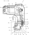
- FIG. 5 is a sectional view of a housing of a circular saw section cut along a line VV shown in FIG. 4.
- the enlarged view of the gear case shown in FIG. Sectional drawing which shows the air path formed in a housing. Sectional drawing which shows the air path formed in the housing of the tabletop cutting machine which is the 2nd Embodiment of this invention. Sectional drawing of the housing of the tabletop cutting machine which is the 3rd Embodiment of this invention.
- V pulley which functions as an axial fan.
- Sectional drawing which shows the air path formed in the housing shown in FIG. Sectional drawing of the housing of the tabletop cutting machine which is the 4th Embodiment of this invention.
- the perspective view of the timing pulley which functions as an axial fan.
- Sectional drawing which shows the air path formed in the housing shown in FIG. Sectional drawing of the housing of the tabletop cutting machine which is the 5th Embodiment of this invention.
- Sectional drawing which shows the air path formed in the housing shown in FIG. Sectional drawing of the housing of the tabletop cutting machine which is the 6th Embodiment of this invention.
- Sectional drawing of the housing of the tabletop cutting machine which is the 7th Embodiment of this invention.
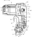
- the tabletop cutting machine 1 is mainly composed of a base part 2, a holder 3, and a circular saw part 4.
- a circular saw part 41 is mounted on the circular saw part 4 as a tip tool.
- the circular saw part 4 can be tilted with respect to the base part 2 in a direction perpendicular to the side surface of the saw blade 41.
- the base part 2 On the other hand, the circular saw portion 4 is configured to be swingable in the direction of approaching and separating.
- the base portion 2 is mainly composed of a base 21 that can be placed on a floor surface, a turntable 22 carried on the base 21, and a fence 23 provided on the base 21.
- the upper surface of the turntable 22 is substantially flush with the upper surface of the base 21, and the turntable 22 is connected to the base 21 so as to be rotatable about a rotation axis orthogonal to the upper surface.
- the workpiece W is placed on the base 21 and the turntable 22.
- the turntable 22 and the base 21 are formed with a groove portion (not shown) that allows the saw blade 41 to enter when the circular saw portion 4 is lowered.
- the base 21 and the turntable 22 are an example of a placement surface.
- the fence 23 includes a right fence 23 ⁇ / b> A and a left fence 23 ⁇ / b> B, and each fence includes a pressing surface 23 a that is substantially orthogonal to the upper surface of the base 21.
- each fence includes a pressing surface 23 a that is substantially orthogonal to the upper surface of the base 21.
- an operation unit 24 for performing a turning operation of the turntable 22 and a turning position fixing operation is provided.
- a tilting shaft 25 and a protruding part 26 are provided.
- the tilt shaft 25 extends in the front-rear direction so that the center axis thereof coincides with the upper surface of the turntable 22.
- the protruding portion 26 protrudes upward and has a long hole 26 a (FIG. 3) formed in an arc shape around the central axis of the tilting shaft 25.
- the holder 3 is erected upward as a support portion at the rear portion of the turntable 22, and the lower portion of the holder 3 is provided to be rotatable around the tilting shaft 25. Therefore, the holder 3 can tilt in the left-right direction with respect to the turntable 22.
- the holder 3 is formed with a screw hole 3a at a position coinciding with the above-described long hole 26a, and the clamp lever 31 is screwed into the screw hole 3a. Specifically, the screw portion of the clamp lever 31 passes through the long hole 26a and is screwed into the screwing hole 3a.
- the clamp lever 31 By operating the clamp lever 31 in the release direction, the pressing force against the surface of the protruding portion 26 of the clamp lever 31 is released, so that the holder 3 tilts around the tilt shaft 25 within the arc length range of the long hole 26a. it can.
- a pressing force is applied to the surface of the protruding portion 26 of the clamp lever 31, so that the holder 3 is fixed to the protruding portion 26 at a desired inclination angle. Therefore, it is fixed to the turntable 22.
- the above configuration is an example of a tilt mechanism.
- Two holders which are positioning means for tilting, are provided on the side surface of the holder 3 on the base part side, and two stopper bolts (not shown) are positioned on the movement trajectory of the stopper on the upper surface of the turntable 22. And it is screwed.
- the stopper comes into contact with each head of the stopper bolt at a predetermined tilt angle, and the tilt position of the circular saw portion 4 is positioned.
- One stopper bolt is provided so as to engage with one stopper when the holder 3 is tilted 45 degrees to the left.
- the other stopper bolt is provided so as to engage with the other stopper when the holder 3 is tilted to a position of 45 degrees in the right direction.
- a swing shaft 32 extending in a direction orthogonal to the side surface of the saw blade 41 is provided at the upper end portion of the holder 3.
- the tilting range of the circular saw part 4 depends on the length of the circular saw part 4 in the tilting direction. If the length of the circular saw part 4 in the tilting direction is short, the tilting range can be increased accordingly.
- the circular saw portion 4 is provided so as to be able to swing in the base portion direction and the counter-base portion direction around the swing shaft 32.
- FIG. 4 shows a side view of the tabletop cutting machine 1 when the circular saw part 4 is swung toward the base part 2 around the rocking shaft 32 and cutting of the workpiece W is started.
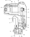
- FIG. 5 shows a side view of the first embodiment of the housing 40 of the circular saw section 4 when the tabletop cutting machine 1 shown in FIG. 4 is cut along the line VV.
- the housing 40 of the tabletop cutting machine 1 includes a saw cover 42 that covers a part of the outer periphery of the saw blade 41, and a spindle 43 that is connected to the saw cover 42 and serves as the rotation center of the saw blade 41.
- a gear case 44 that covers the motor 6 a main housing 45 that is connected to the gear case 44 and accommodates part of the transmission mechanism 5 described later, and a motor housing 46 that is connected to the main housing 45 and covers the motor 6. Composed.
- the spindle 43 is an example of an output shaft.
- a spring (not shown) is provided on the outer periphery of the swing shaft 32, and the circular saw portion 4 is urged by the spring so that the saw blade 41 is moved away from the base portion 2 (upward). It is located at the position swung upwards as shown in FIG. 1 by a stopper mechanism (not shown). The cutting process is performed by swinging the circular saw portion 4 downward with the swing shaft 32 as a fulcrum against the urging force of the spring. When the circular saw portion 4 is swung downward, the saw blade 41 enters a groove (not shown) provided in the turntable 22 and is swung by a stopper mechanism (not shown) in a state where a predetermined amount has entered. Stopped.
- the saw blade 41 is supported by the spindle 43 and is rotated coaxially and integrally with the spindle 43.
- the gear case 44 houses a first pulley 51 as a rotating member, a pulley shaft 52 as an intermediate shaft, and a second pulley 53.
- the gear case 44 is an example of a case.
- the first pulley 51 is a toothed pulley (timing pulley) in which a plurality of teeth are formed on the outer peripheral surface at a predetermined interval.
- the first pulley 51 is connected to the spindle 43 and coaxially and rotates integrally with the spindle 43.
- the pulley shaft 52 is disposed inside the gear case 44 so that the center thereof is parallel to the center axis of the spindle 43.
- a second pulley 53 is provided coaxially and integrally with the pulley shaft 52 on one end side of the pulley shaft 52 adjacent to the saw blade 41.
- the second pulley 53 is a toothed pulley (timing pulley) in which a plurality of teeth are formed at predetermined intervals on the outer peripheral surface. More specifically, the second pulley 53 has teeth (grooves) extending in the circumferential direction in parallel with the rotation axis (left and right direction) on the outer circumferential surface.
- first pulley 51 and the second pulley 53 are arranged so that the outer peripheral surfaces thereof face each other with a gap in the direction in which the side surface of the saw blade 41 extends.
- the first belt 54 is stretched between the two. More specifically, teeth (grooves) extending in a direction parallel to the rotation axis are formed on the first belt 54 side by side in the circumferential direction on the inner circumferential surface.
- the rotation of the second pulley 53 is transmitted to the first pulley 51 by the rotation of the first belt 54.
- the first belt 54 is a toothed belt such as a timing belt.
- the second pulley 53 is an example of a third rotating member
- the first belt 54 is an example of a second belt
- the first pulley 51 is an example of a fourth rotating member.
- the transmission mechanism formed by the second pulley 53, the first belt 54, and the first pulley 51 is an example of a second transmission mechanism.
- the gear case 44 is formed with a first opening 71 at a position on the outer peripheral surface facing the workpiece W placed on the base portion 2 and in the vicinity of the toothed surface of the first pulley 51. .
- the first opening 71 communicates the inside and the outside of the gear case 44 as an exhaust port.
- the first opening 71 has a shape and a size such that the cooling air discharged from the first opening 71 is directed to the workpiece W.
- the gear case 44 in which the first opening 71 is formed and the workpiece W define a working space.
- the spindle 43 is rotatably supported by a bearing holder 47 attached to the gear case 44 via a bearing 61, protrudes to the outside of the gear case 44, and is formed so that the rotation center of the saw blade 41 can be attached to the tip portion thereof.
- a second opening 72 is formed as an exhaust port on the surface of the bearing holder 47 facing the saw blade 41.
- the second opening 72 communicates the inside and the outside of the gear case 44.
- the second opening 72 has a shape and a size such that the cooling air discharged from the second opening 72 is directed to the saw blade 41.
- the second opening 72 is formed in an arc shape centering on the spindle 43 on the surface facing the saw blade 41 of the bearing holder 47.
- the second opening 72 faces the saw blade 41 of the bearing holder 47 so as to be positioned between the spindle 43 and the base 21 when the circular saw portion 4 is swung toward the base portion 2. Formed on the surface.
- the main housing 45 communicates with the gear case 44 through the communication space S ⁇ b> 1 and accommodates the third pulley 55 and the fourth pulley 56.
- the third pulley 55 is connected to the other end of the pulley shaft 52 at the same center as the pulley shaft 52 and rotates integrally with the pulley shaft 52.
- the pulley shaft 52 is supported by a bearing 62 so as to be rotatable with respect to the main housing 45.
- the fourth pulley 56 is connected coaxially with the output shaft 6A of the motor 6 and rotates integrally with the output shaft 6A. Further, the third pulley 55 and the fourth pulley 56 are arranged so that the outer peripheral surfaces thereof face each other in the direction in which the side surface of the saw blade 41 extends, and between the third pulley 55 and the fourth pulley 56.
- the second belt 57 is stretched.
- the second belt 57 is a toothed belt such as a timing belt.
- the first pulley 51, the pulley shaft 52, the second pulley 53, the first belt 54, the third pulley 55, the fourth pulley 56, and the second belt 57 are transmission mechanisms that transmit the output of the motor 6 to the saw blade 41. 5 is configured.
- each of the third pulley 55 and the fourth pulley 56 may be a V pulley formed such that a V groove extends in the circumferential direction on the cylindrical surface.
- the second belt 57 is a V belt.
- the output shaft 6A of the motor 6 is an example of a rotating shaft
- the fourth pulley 56 is an example of a first rotating member
- the second belt 57 is an example of a first belt
- the third pulley 55 is a second pulley. It is an example of a rotating member.
- the transmission mechanism formed by the fourth pulley 56, the second belt 57, and the third pulley 55 is an example of a first transmission mechanism.
- the communication space S1 is an example of an air inlet provided in the housing. Accordingly, the communication space S ⁇ b> 1 is located on one side of the gear case 44 near the main housing 45, and the second opening 72 is located on the other side of the gear case 44 near the saw blade 41.
- the motor housing 46 is formed in a cylindrical shape that accommodates the motor 6 and the cooling fan 7, and one end in the axial direction communicates with the main housing 45.
- the motor 6 is arranged such that the output shaft 6A extends toward the main housing 45, is parallel to the spindle 43 serving as the rotation shaft of the saw blade 41, and intersects with an extension line on the side surface of the saw blade 41.
- the cooling fan 7 is fixed to the output shaft 6A.
- the rotational force of the motor 6 is transmitted to the fourth pulley 56 that rotates integrally with the output shaft 6 ⁇ / b> A, and is transmitted to the transmission mechanism 5.
- the output shaft 6A is an example of a motor rotation shaft
- the cooling fan 7 is an example of a fan or a motor fan.
- a plurality of slit-shaped openings are formed as wind windows 48 at the other end of the motor housing 46 so that outside air can be introduced into the motor housing 46.
- a saw cover 49 (FIG. 1) having a shape covering the outer peripheral portion of the saw blade 41 protruding from the saw cover 42 is rotatably provided. As shown in FIG. 1, the saw cover 49 rotates to a position covering the outer periphery of the saw blade 41 at a portion protruding from the saw cover 42 when the circular saw portion 4 is swinging upward.
- the saw cover 49 is housed in the saw cover 42 by a link mechanism (not shown) in a state where the circular saw portion 4 is swinging downward, and the outer periphery of the saw blade 41 protruding from the saw cover 42 is exposed. To turn.
- the main housing 45 is integrally provided with a handle portion 8 located on an extension line of the side surface of the saw blade 41.
- the handle portion 8 is provided with a switch 9 for controlling the driving of the motor 6.
- the motor housing 46 is provided with a fixing mechanism (not shown) that fixes the movement of the circular saw portion 4 relative to the base portion 2 in a state where the circular saw portion 4 swings to the lowest position. By using the fixing mechanism, the tabletop cutting machine can be easily transported.
- the switch 9 provided on the handle portion 8 is operated to rotate the motor 6 and rotate the saw blade 41 around the spindle 43.
- the handle portion 8 is gripped, the circular saw portion 4 is pushed down against the biasing force of the spring, and the workpiece W is cut.
- the saw blade 41 enters the groove portion of the turntable 22 and the cutting force of the circular saw portion 4 is released when the workpiece W has been cut, the circular saw portion 4 is moved to the original upper limit position by the biasing force of the spring.
- the fourth pulley 56 rotates together with the rotation of the output shaft 6A, and the rotation of the fourth pulley 56 is transmitted to the third pulley 55 via the second belt 57, so that the third pulley 55 rotates.
- the second pulley 53 rotates with the rotation of the third pulley 55, and the rotation of the second pulley 53 is transmitted to the first pulley 51 via the first belt 54, so that the first pulley 51 rotates. Since the spindle 43 rotates with the rotation of the first pulley 51 and the saw blade 41 rotates, the workpiece W can be cut by the saw blade 41.
- the cooling fan 7 rotates along with the rotation of the motor 6, and outside air is taken into the motor housing 46 as cooling air from the wind window 48 along with the rotation of the cooling fan 7. Since the motor housing 46 and the main housing 45 communicate with each other, and the main housing 45 communicates with the gear case 44 via the communication space S1, the cooling air taken into the motor housing 46 cools the motor 6, Next, the main housing 45 is entered and cooled by sequentially passing by the fourth pulley 56, the second belt 57, and the third pulley 55 in the main housing 45.
- the cooling air enters the gear case 44 through the communication space S ⁇ b> 1, and sequentially passes by the second pulley 53, the first belt 54, and the first pulley 51 in the gear case 44, and then the first opening of the gear case 44. 71 and the second opening 72 of the bearing holder 47 are exhausted to the outside. At this time, the cooling air passes from the communication space S1 to the second opening 72, and escapes from one end side of the second pulley 53, the first belt 54, and the first pulley 51 to the other end side (right side to left side). That is, the cooling air passes through the space where the first belt 54 is stretched between the second pulley 53 and the first pulley 51.
- the cooling air flow path P is formed across the motor housing 46, the main housing 45, the communication space S 1, and the gear case 44 from the wind window 48 to the first opening 71 or the second opening 72. Is done. Since the first to fourth pulleys 51, 53, 55, 56 and the first and second belts 54, 57 constituting the transmission mechanism 5 are located inside the air passage P, the first to fourth pulleys are located. The pulleys 51, 53, 55, 56 and the first and second belts 54, 57 can be cooled by cooling air that directly hits them, and heat generated in these members by driving can be dissipated.
- the first pulley 51 and the first belt 54 are placed in the air path P and directly exposed to the cooling air, the heat generated in the transmission mechanism 5 by the operation of the tabletop cutting machine 1 is efficiently radiated. It is possible. Therefore, deterioration due to heat of components constituting the transmission mechanism 5 including the first pulley 51 and the first belt 54, which are the most heavily loaded in the transmission mechanism, can be suppressed, so that the life can be improved.
- the cooling air passes through all the members that rotate during the work, such as the motor 6 and the saw blade 41, and the entire power transmission path from the motor 6 to the saw blade 41 is cooled. be able to.
- Cooling air is exhausted to the outside from the first opening 71 of the gear case 44 and the second opening 72 of the bearing holder 47 adjacent to the saw blade 41. At this time, the cooling air exhausted from the second opening 72 hits the side surface of the saw blade 41 and changes the traveling direction. Further, the cooling air that tends to flow in the direction approaching the wind window 48 is regulated by the spindle 43. Therefore, most of the cooling air exhausted from the first opening 71 and the second opening 72 flows in a direction away from the wind window 48. Thereby, it is possible to effectively suppress the exhaust that has absorbed the heat generated in the transmission mechanism 5 from moving toward the wind window 48, and to suppress the circulation of the cooling air (exhaust).
- the chips generated by cutting the workpiece W approach the first opening 71 and the second opening 72
- the chips from the first opening 71 and the second opening 72 to the inside of the gear case 44 due to the momentum of exhaust. Can be prevented from entering.
- the opening area per one can be reduced, and the plurality of opening portions (the first opening 71 and the second opening 72) face in different directions. Since it comprised so, it can suppress that a chip
- first opening 71 and the second opening 72 are provided in the lower portion of the gear case 44, even if dust such as chips enters the gear case 44, dust accumulated in the lower portion in the gear case 44 due to gravity. Can be suitably discharged by exhausting air from the first opening 71 and the second opening 72. In particular, since the first opening 71 opens downward, it is easier to discharge dust. Further, before starting the work, the exhaust from the second opening 72 is guided by the side surface of the saw blade 41 and reaches the end portion (blade edge) of the saw blade 41. Therefore, since the exhaust gas can eliminate chips adhering to the saw blade 41 including the cutting edge, it is possible to suppress a decrease in cutting performance.
- the cooling air discharged from the first opening 71 and the second opening 72 is covered. Since the chips are blown off by hitting the processed member W, the visibility of the cut portion by the saw blade 41 can be improved. That is, the cooling air discharged from the first opening 71 and the second opening 72 can be used as a blower for chips. Further, the chips scattered in the air also move away from the wind window 48 due to the air flow away from the wind window 48, so that it is possible to prevent the chips from entering the motor housing 46.
- the communication space S ⁇ b> 1 that functions as an intake port and the second opening 72 that functions as an exhaust port are provided so as to be separated in a direction orthogonal to the axial direction of the spindle 43.
- the spindle 43, the first pulley 51, a part of the first belt 54, and the bearing 61 are arranged so as to be positioned between the communication space S ⁇ b> 1 and the second opening 72 in a direction orthogonal to the axial direction of the spindle 43. .
- the cooling air escapes from the second pulley 53 side of the first pulley 51 to the opposite side (vertical direction in the figure), so that the spindle 43, the first pulley 51, a part of the first belt 54, and the bearing 61 are removed. It can be cooled effectively.
- the communication space S1 functioning as an intake port and the second opening 72 functioning as an exhaust port are provided so as to be separated in a direction parallel to the axial direction of the spindle 43.
- the cooling air flows from one end side of the rotation shaft of the second pulley 53, the first belt 54 and the first pulley 51 to the other end side (from the right side to the left side), and from the second pulley 53 side of the first pulley 51.
- the spindle 43, the first pulley 51, the second pulley 53, the first belt 54, and the bearing 61 can be effectively cooled because they come out in the opposite direction (vertical direction in the figure). Further, the cooling air passes through a space where the first belt 54 is stretched between the first pulley 51 and the second pulley 53. In other words, the cooling air passes through the first belt 54 in a direction crossing the stretching direction of the first belt 54. Therefore, even if shavings are generated from the first belt 54 due to wear due to the work load and the shavings adhere to the second pulley 53 and the first pulley 51, the right to left so as to cross the first belt 54. Shavings can be eliminated by the cooling air flowing through.
- first pulley 51 and the second pulley 53 which are timing pulleys, are formed with grooves extending in the direction parallel to the rotation axis (left and right direction), so that the cooling air flows along the grooves.
- the dust adhering in the groove can be suitably eliminated.
- the wind window 48 for taking in the cooling air into the housing and the first opening 71 and the second opening 72 for discharging the cooling air from the gear case 44 are provided apart from each other, the first opening 71 and the second opening 72 are provided.
- the recirculation of the cooling air exhausted from the air is taken into the housing again through the air window 48 and passes through the air passage P is suppressed. Therefore, since the outside air that does not always include exhaust heat can be taken into the housing, the transmission mechanism 5 can be efficiently cooled.
- the gear occlusion is not used to transmit the rotation of the motor 6 to the saw blade 41, it is necessary to use the lubricating oil indispensable for the gear occlusion and to seal the gear case 44 for suppressing the leakage of the lubricating oil. And not. Therefore, the gear case 44 can be reduced in size, and an opening can be formed in the gear case 44 itself, so that the cooling air can be directly applied to the first pulley 51 integrated with the spindle 43. Efficiency can be improved.
- the output of the motor 6 is transmitted to the saw blade 41 using the belts 54 and 57 instead of the engagement of the gear, the volume of the transmission mechanism 5 occupying the housing is reduced and the transmission mechanism 5 is reduced in weight.
- the cooling air flow path P can be widely provided in the housing. Furthermore, since the meshing of the gear made of metal is eliminated, noise is reduced.
- the location of the first opening 71 in the gear case 44 can be provided in an appropriate location of the gear case 44 regardless of the above embodiment as long as the first pulley 51 can be cooled by cooling air. is there.
- the 1st opening 71 and the 2nd opening 72 were provided as a discharge port of cooling air, only any one may be sufficient.
- the bearing holder 47 is provided as a separate member from the gear case 44, but the bearing holder 47 may be provided integrally with the gear case 44.
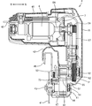
- FIG. 8 shows a housing of a tabletop cutting machine according to the second embodiment of the present invention.
- the same reference numerals are given to portions common to the embodiments described in FIGS. 1 to 7.
- the housing shown in FIG. 8 is different from the embodiment described in FIGS. 1 to 7 in that the first opening 71 and the second opening 72 are not provided, and a third opening 73 is newly formed.
- the third opening 73 is formed as an exhaust port on the surface of the gear case 44 facing the saw blade 41.
- the third opening 73 communicates the inside and the outside of the gear case 44.
- the third opening 73 is formed between the first pulley 51 and the second pulley 53 in the direction parallel to the side surface of the saw blade 41 on the outer peripheral surface of the gear case 44.
- the third opening 73 is defined inside the gear case 44 and is formed so as to face a space where the first belt 54 between the first pulley 51 and the second pulley 53 is stretched.
- the third opening 73 is provided at a position facing the communication space S ⁇ b> 1 so that the cooling air that has passed through the communication space S ⁇ b> 1 can reach the third opening 73 directly.
- the third opening 73 is formed in an arc shape centering on the spindle 43 on the surface of the bearing holder 47 facing the saw blade 41.
- the cooling air passes through the communication space S1, it passes from the right to the left through the space where the first belt 54 between the first pulley 51 and the second pulley 53 is stretched, and the third The air is exhausted from the opening 73 to the outside. That is, the air path P from the communication space S ⁇ b> 1 is formed so as to pass from the communication space S ⁇ b> 1 between the first pulley 51 and the second pulley 53 to the third opening 73.
- the communication space S1 and the third opening 73 are provided so as to be separated in a direction parallel to the axial direction of the spindle 43, and each of the communication space S1 and the third opening 73 is a pulley. They are arranged so as to be located between the central axis of the shaft 52 and the central axis of the spindle 43.
- the cooling air passing through the gear case 44 is formed to concentrate between the first pulley 51 and the second pulley 53. Therefore, even if shavings are generated from the first belt 54 due to wear due to the work load and the shavings adhere to the second pulley 53 and the first pulley 51, the right to left so as to cross the first belt 54.
- first pulley 51 and the second pulley 53 which are toothed pulleys, are formed with grooves extending in the direction parallel to the rotation axis (left and right direction), so that the cooling air flows along the grooves.
- the dust adhering to the inside of the grooves of the first pulley 51 and the second pulley 53 can be more suitably eliminated.
- the housing 140 has a shape that covers a saw cover 42 that covers a part of the outer periphery of the saw blade 41, and a spindle 43 that is connected to the saw cover 42 and serves as the rotation center of the saw blade 41.
- a fourth opening 74 is formed on the outer peripheral surface facing the saw blade 41 so as to communicate the inside and the outside of the gear case 144, and functions as an exhaust port.
- the fourth opening 74 is located between the first pulley 51 and the second pulley 53 on the outer peripheral surface of the gear case 144.
- the fourth opening 74 is formed in the gear case 144 at a position facing the space where the first belt 54 is stretched between the first pulley 51 and the second pulley 53. Further, the fourth opening 74 is provided at a position facing the communication space S ⁇ b> 1 so that the cooling air that has passed through the communication space S ⁇ b> 1 reaches the fourth opening 74 directly.
- the fourth opening 74 is formed in an arc shape centering on the spindle 43 on the surface of the gear case 144 facing the saw blade 41.
- the main housing 145 has a fifth opening 75 formed on the motor 6 side and a sixth opening 76 formed on the pulley shaft 52 side.
- a partition wall 145 ⁇ / b> A that protrudes inward is provided at a substantially intermediate position between the third pulley 55 and the fourth pulley 56 on the inner surface of the main housing 145 that faces the transmission mechanism 5.
- the partition wall 145A includes a motor cooling air passage W1 formed in the motor housing 46 by the rotation of the fan 7 and a transmission mechanism cooling air passage W2 formed in the gear case 144 in the main housing 145 independently of each other.
- the motor cooling air passage W1 and the transmission mechanism cooling air passage W2 are formed in such a size that they are prevented from crossing each other and the motor cooling air passage W1 and the transmission mechanism cooling air passage W2 are made independent of each other.
- each of the third pulley 155 and the fourth pulley 56 is a V pulley
- the second belt 57 is a toothed belt.
- the third pulley 155 includes a rotation shaft core 155A that is fixed coaxially to the pulley shaft 52, a cylindrical portion 155B on which the second belt 57 is suspended, and a cylindrical portion 155B that rotates.
- a plurality of wing portions 155C are formed between the shaft core 155A and the gap 155d in the circumferential direction.
- the cylindrical portion 155B has a V-groove extending in the circumferential direction on the surface, and at least one V-groove is formed side by side in the rotation axis direction.
- the plurality of wing portions 155C are radially formed so that each extends from the rotation axis 155A to the cylindrical portion 155B.
- a plurality of wing portions 155C are formed in the circumferential direction via gaps 155d.
- the plurality of wing portions 155C When the plurality of wing portions 155C are rotated around the rotating shaft core 155A, the plurality of wing portions 155C have a shape that functions as an axial fan, and generate wind that passes through the gap 155d and travels toward the second pulley 53.
- the number and specific shape of the wings 155C are appropriately set according to the strength of the cooling air generated by the third pulley 155 as an axial fan.
- the fourth pulley 56 rotates along with the rotation of the output shaft 6A, and the rotation of the fourth pulley 56 is transmitted to the third pulley 155 via the second belt 57, so that the third pulley 56 is rotated.
- Pulley 155 rotates.
- the second pulley 53 rotates with the rotation of the third pulley 155, and the rotation of the second pulley 53 is transmitted to the first pulley 51 via the first belt 54, so that the first pulley 51 rotates. Since the spindle 43 rotates with the rotation of the first pulley 51 and the saw blade 41 rotates, the workpiece W can be cut by the saw blade 41.
- the cooling fan 7 rotates with the rotation of the motor 6, so that outside air is taken into the motor housing 46 as cooling air from the wind window 48.
- the cooling air flows from the motor housing 46 into the main housing 145, but is prevented from moving toward the communication space S ⁇ b> 1 by the partition wall 145 ⁇ / b> A and is discharged to the outside of the housing 140 through the fifth opening 75. That is, a motor cooling air passage W ⁇ b> 1 extending from the wind window 48 to the fifth opening 75 is formed in the housing 140.
- the cooling air flowing through the air passage W1 cools the motor 6 located in the air passage W1, and the fourth pulley 56 and a part of the second belt 57.
- the third pulley 155 when the third pulley 155 rotates, it also functions as an axial fan and generates a wind toward the second pulley 53, so that outside air is taken in as cooling air from the sixth opening 76.
- the taken cooling air passes through the space 155d in the cylindrical portion 155B of the third pulley 155, passes through the space between the first and second pulleys 51 and 53, and passes through the fourth opening 74 to the outside of the housing 140. Discharged. That is, a transmission mechanism cooling air passage W2 including a part of the third pulley 155 and the first and second pulleys 51 and 53 is formed from the sixth opening 76.
- the cooling air flowing through the air passage W2 passes through the third pulley 155, the first and second pulleys 51 and 53, a part of the first belt 54, and the side of the bearing 61, and passes through the fourth opening 74 of the gear case 144. It is exhausted to the outside through.
- the third pulley 155 is more efficient from both the outer peripheral surface side and the inner peripheral surface side than when there is no gap 155c. Cools well. Further, since the third pulley 155 functions as an axial fan, the cross section in the traveling direction of the transmission mechanism cooling air passage W2 can be widened, a space having a cooling effect can be provided widely, and heat generation by driving in particular.
- the first, second and third pulleys 51, 53, 155 and the bearings 61, 62 having a large amount can be efficiently cooled.
- the first, second, and third pulleys 51, 53, and 155 and the bearings 61 and 62 to be cooled are examples of rotating members in the present invention.
- the motor cooling air passage W1 from the air window 48 toward the fifth opening 75 and the transmission mechanism cooling air passage W2 from the sixth opening 76 passing through the inside of the cylindrical portion 155B of the third pulley 155 toward the fourth opening 74 are provided. Are formed in the housing 140. Since the motor 6, the fourth pulley 56, and a part of the second belt 57 are located in the motor cooling air passage W1, these parts can be cooled by the cooling air directly exposed to the drive. The heat generated by can be efficiently radiated. On the other hand, a part of the second belt 57, the first to third pulleys 51, 53, 55, the first belt 54, and the bearings 61, 62 are located in the transmission mechanism cooling air passage W2. Since it is directly cooled by the cooling air that is taken in from the outside that is not heated by the exhaust heat of the motor 6, the heat generated in these members by driving can be efficiently radiated.
- the cooling air of any one of the air passages W 1 and W 2 passes through all members that operate during the work, such as the motor 6 and the saw blade 41, and the entire interior of the housing 140 is configured. Can be cooled.
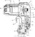
- the housing 240 of the tabletop cutting machine 1 according to the fourth embodiment will be described with reference to FIGS.
- the same components will be denoted by the same reference numerals, and detailed description thereof will be omitted.
- the configuration of the first pulley 251 and the position of the opening provided in the gear case 244 are different from the third embodiment. Since the other configuration is the same as that of the third embodiment, description of each component is omitted.
- the housing 240 of the tabletop cutting machine 1 includes a saw cover 42, a gear case 244 that is connected to the saw cover 42 and covers a spindle 43 that serves as a rotation center of the saw blade 41, and a gear case 244.
- the main housing 145 is connected to accommodate a part of the transmission mechanism 5, and the motor housing 46 is connected to the main housing 145 and covers the motor 6.
- a seventh opening 77 is formed in the gear case 244 on the outer peripheral surface facing the workpiece W placed on the base portion 2 and in the vicinity of the toothed surface of the first pulley 251.
- the seventh opening 77 serves as an exhaust port and allows communication between the inside and the outside of the gear case 244.
- the seventh opening 77 has a shape and a size such that the cooling air discharged from the seventh opening 77 is directed to the workpiece W.
- the bearing holder 247 is also formed with an eighth opening 78 that allows the gear case 244 to communicate with the outside via the bearing holder 247.
- the eighth opening 78 is formed on the surface of the bearing holder 247 that faces the saw blade 41.
- each of the first pulley 251 and the second pulley 53 is a timing pulley
- the first belt 54 is a toothed belt.
- the first pulley 251 includes a rotating shaft core 251A that is fixed coaxially to the spindle 43, a cylindrical portion 251B on which the first belt 54 is suspended, and a cylindrical portion 251B.
- a plurality of wings 251C are formed between the rotary shaft core 251A and the gap 251d in the circumferential direction.
- protrusions extending in the rotation axis direction are formed as teeth in the circumferential direction at intervals.
- the plurality of wing portions 251C are radially formed so that each extends from the rotation axis 251A to the cylindrical portion 251B.
- a plurality of wing portions 251C are formed in the circumferential direction via gaps 251d.
- the plurality of wing portions 251C When the plurality of wing portions 251C are rotated around the rotation axis 251A, the plurality of wing portions 251C have a shape that functions as an axial fan, and generate wind that passes through the gap 251d and travels toward the saw blade 41 side.
- the number and specific shape of the wings 155C are appropriately set according to the strength of the cooling air generated by the first pulley 251 as an axial fan.
- the fourth pulley 56 rotates along with the rotation of the output shaft 6A, and the rotation of the fourth pulley 56 is transmitted to the third pulley 55 via the second belt 57, so that the third pulley 56 rotates.
- the pulley 55 rotates.
- the second pulley 53 rotates with the rotation of the third pulley 55, and the rotation of the second pulley 53 is transmitted to the first pulley 251 via the first belt 54 and the first pulley 251 rotates. Since the spindle 43 rotates with the rotation of the first pulley 251 and the saw blade 41 rotates, the workpiece W can be cut by the saw blade 41.
- the cooling fan 7 rotates with the rotation of the motor 6, and the outside air is taken into the motor housing 46 as cooling air from the wind window 48 with the rotation of the cooling fan 7.
- the cooling air flows from the motor housing 46 into the main housing 45, but is prevented from proceeding toward the communication space S ⁇ b> 1 by the partition wall 145 ⁇ / b> A and is discharged to the outside of the housing 240 through the fifth opening 75. That is, a motor cooling air passage W11 extending from the wind window 48 to the fifth opening 75 is formed in the housing 240, and the motor 6, the fourth pulley 56, and a part of the second belt 57 are formed by the cooling air flowing through the air passage W1. And are cooled.
- the first pulley 251 also functions as an axial fan when rotated, the outside air is taken in as cooling air from the sixth opening 76, and the cooling air passes through the outer peripheral surface of the third pulley 55, and further communicates with the communication space. It passes through the inside of the cylindrical portion 251 ⁇ / b> B of the first pulley 251 through S ⁇ b> 1 and is discharged to the outside of the housing 240 through the seventh opening 77 or the eighth opening 78. That is, a transmission mechanism cooling air passage W12 including a part of the third pulley 55, the first pulley 251, and the second pulley 53 is formed from the sixth opening 76.
- the cooling air flowing through the air passage W12 passes through the second belt 57, the third pulley 55, the second pulley 53, the first pulley 251, a part of the first belt 54, the bearings 61 and 62, and the seventh opening 77. Alternatively, the air is exhausted to the outside through the eighth opening 78.
- the first pulley 251 can be efficiently cooled compared to the case without the gap 251c. Further, since the first pulley 251 functions as an axial fan, a cross section with respect to the traveling direction of the transmission mechanism cooling air passage W12 can be widened, and a space having a cooling effect can be widened. In particular, the first pulley 251 and the third pulley 55 and the bearings 61 and 62 that generate a large amount of heat generated by driving can be efficiently cooled.
- the motor cooling air passage W11 from the air window 48 toward the fifth opening 75 and the transmission mechanism cooling air passage W12 from the sixth opening 76 toward the seventh opening 77 or the eighth opening 78 are formed in the housing 240. Is done. Since the motor 6, the fourth pulley 56, and a part of the second belt 57 are located in the motor cooling air passage W11, these parts can be cooled by the cooling air directly exposed to the drive. The heat generated by can be efficiently radiated. On the other hand, a part of the second belt 57, the first to third pulleys 251, 53, 55, the first belt 54, and the bearings 61, 62 are located in the transmission mechanism cooling air passage W12. Since it is directly cooled by the cooling air that is taken in from the outside that is not heated by the exhaust heat of the motor 6, the heat generated in these members by driving can be efficiently radiated.
- any of the cooling air passes through all members that rotate during the operation, such as the motor 6 and the saw blade 41, and the inside of the housing 240 can be cooled as a whole.
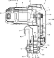
- a desktop cutting machine housing 340 according to a fifth embodiment of the present invention will be described with reference to FIGS. 15 and 16.
- the third and fourth embodiments are different from the third and fourth embodiments in that the pulley 251 that also functions as the axial fan used in the fourth embodiment is used as the first pulley, and the third pulley is the third pulley.
- a pulley 155 that also functions as the axial fan used in the embodiment is used.
- the gear case 344 is positioned on the outer peripheral surface facing the saw blade 41 at an opening 79 facing the intermediate position between the first pulley 251 and the second pulley 53, and on the opposite side of the spindle 43 from the opening 79.
- An opening 80 formed in the bearing holder 347 facing the saw blade 41 and an opening 81 on the surface facing the gear case 344 of the cylindrical portion 251B of the first pulley 251 are formed.
- the openings 79, 80, and 81 function as cooling air exhaust ports when the motor 6 is driven.
- the third pulley 155 when the third pulley 155 rotates, it also functions as an axial fan and generates a wind toward the second pulley 53, so that outside air is taken in as cooling air from the sixth opening 76.
- the taken cooling air passes through the space 155d in the cylindrical portion 155B of the third pulley 155, passes through the space between the first and second pulleys 251 and 53, and opens in the housing 340 through the openings 79, 80, and 81. It is discharged outside. That is, the transmission mechanism cooling air passage W22 including the third pulley 155, the second pulley 53, and the first pulley 251 is formed from the sixth opening 76.
- the cooling air flowing through the air passage W22 passes through the third pulley 155, the second pulley 53, the first pulley 251, the first belt 54, and the bearings 61 and 62, and passes through the openings 79, 80, and 81. Exhausted outside.
- the third pulley 155 is more efficient from both the outer peripheral surface side and the inner peripheral surface side than when there is no gap 155c. Cools well. Further, since the third pulley 155 functions as an axial fan, the cross section in the traveling direction of the transmission mechanism cooling air passage W22 can be widened, a space having a cooling effect can be provided large, and heat generation by driving in particular. The first, second and third pulleys 251, 53 and 155 and the bearings 61 and 62 having a large amount can be efficiently cooled.
- the first pulley 251 and the third pulley 155 function as an axial fan that generates cooling air that is directed toward the saw blade 41 in conjunction with each other. That is, in the transmission mechanism cooling air passage W22, since the two fans cooperate to generate cooling air, the air volume can be increased, and the cooling effect of the first pulley 251 and the third pulley 155 and the bearings 61 and 62 is enhanced. It is possible to prevent deterioration of these parts due to heat.
- the housing 440 of the sixth embodiment removes the cooling fan 7 from the housing 40 of the first embodiment, uses a pulley 251 that functions as an axial fan as a first pulley, and a shaft as a third pulley. A pulley 155 that functions as a flow fan is used.
- the motor housing 446 of the housing 440 is formed smaller than the motor housing 46 by the amount that the cooling fan is not provided.
- the first pulley 251 and the third pulley 155 are rotated by the transmission mechanism 5 to generate a wind toward the saw blade 41 side. Since no opening is formed in the main housing 45, outside air is introduced into the motor housing 446 as cooling air from the wind window 48, and cooling air flows toward the gear case 44 through the motor housing 446 and the main housing 45. The cooling air flows in the cylindrical portion 155 B of the third pulley 155 and the cylindrical portion 251 B of the first pulley 251, and is discharged to the outside of the housing 40 through the opening 71.
- the output shaft 6A of the motor 6 can be shortened, and as a result, the length of the saw blade 41 of the motor housing 446 in the rotation axis direction can be shortened. Accordingly, since the housing 440 itself can be made compact, the tilt angle range of the tabletop cutting machine 1 can be widened, and the operability of the tabletop cutting machine 1 can be improved.
- FIG. 18 is a sectional view of a disc grinder 500 to which the present invention is applied.
- a disc grinder 500 shown in FIG. 18 has a pulley 503 attached to an output shaft 502 on which a disc 501 as a tip tool is attached, instead of a final reduction portion formed by meshing gears that have been conventionally attached.
- the disc 501 is rotated by a belt drive of a pulley 505 mechanically connected to the output shaft of the motor 504.
- the pulleys 503 and 505 have a plurality of wings formed around the rotation axis within the cylindrical portion around which the belt is suspended, and when the pulleys rotate, the pulleys As well as an axial fan.
- the housing 507 is an outer peripheral surface facing the disk 501 and formed in the vicinity of the pulleys 503 and 505, and openings formed on the opposite side of the outer peripheral surface facing the disk 501. 511.
- an air passage W3 having the opening 511 as an intake port and the openings 508, 509 and 510 as an exhaust port is formed in the housing 507.
- An output shaft 502 that rotates at high speed, a bearing 506 that rotatably supports the output shaft 502, and pulleys 503 and 505 are taken into the air passage W3 and directly cooled. Therefore, the power transmission mechanism from the motor 504 to the disk 501 can be reduced in size, and each component can be efficiently cooled to prevent deterioration of the component due to heat.
- the present invention is not limited to a tabletop cutting machine and a disk grinder, and the rotation of a motor is output via a transmission mechanism.
- the present invention can be applied to an appropriate power tool that is transmitted to a shaft and can be operated by a tip tool.
Abstract
Outil motorisé dans lequel des composants contenus dans un carter d'engrenage sont facilement refroidis. Un outil motorisé 1 comporte : un moteur 6 ; un ventilateur 7 entraîné en rotation par le moteur 6 afin de produire un flux d'air de refroidissement ; un logement 42, 44, 45 contenant le moteur 6 et le ventilateur 7 et délimitant un passage d'écoulement d'air P pour l'écoulement d'air de refroidissement ; un arbre de sortie 43 sur lequel un outil d'extrémité avant 41 peut être monté de façon amovible et qui est entraîné en rotation par le moteur 6 ; et un mécanisme de transmission 5 pour transmettre la sortie de rotation du moteur 6 à l'arbre de sortie 43. Le mécanisme de transmission 5 comporte un élément rotatif 51 tournant avec l'arbre de sortie 43, et l'élément rotatif 51 est disposé dans le passage d'écoulement d'air P.
Priority Applications (4)
| Application Number | Priority Date | Filing Date | Title |
|---|---|---|---|
| JP2018553719A JP6750686B2 (ja) | 2016-11-30 | 2017-10-27 | 動力工具 |
| EP17876106.0A EP3549704A4 (fr) | 2016-11-30 | 2017-10-27 | Outil motorisé |
| US16/463,808 US11141804B2 (en) | 2016-11-30 | 2017-10-27 | Power tool |
| CN201780074021.XA CN110023018A (zh) | 2016-11-30 | 2017-10-27 | 动力工具 |
Applications Claiming Priority (4)
| Application Number | Priority Date | Filing Date | Title |
|---|---|---|---|
| JP2016233509 | 2016-11-30 | ||
| JP2016-233509 | 2016-11-30 | ||
| JP2017-090361 | 2017-04-28 | ||
| JP2017090361 | 2017-04-28 |
Publications (1)
| Publication Number | Publication Date |
|---|---|
| WO2018100940A1 true WO2018100940A1 (fr) | 2018-06-07 |
Family
ID=62242257
Family Applications (1)
| Application Number | Title | Priority Date | Filing Date |
|---|---|---|---|
| PCT/JP2017/038896 WO2018100940A1 (fr) | 2016-11-30 | 2017-10-27 | Outil motorisé |
Country Status (5)
| Country | Link |
|---|---|
| US (1) | US11141804B2 (fr) |
| EP (1) | EP3549704A4 (fr) |
| JP (1) | JP6750686B2 (fr) |
| CN (1) | CN110023018A (fr) |
| WO (1) | WO2018100940A1 (fr) |
Cited By (1)
| Publication number | Priority date | Publication date | Assignee | Title |
|---|---|---|---|---|
| CN109227329A (zh) * | 2018-10-12 | 2019-01-18 | 毛勤钧 | 一种适用于切割机的除尘装置及切割机除尘系统 |
Families Citing this family (1)
| Publication number | Priority date | Publication date | Assignee | Title |
|---|---|---|---|---|
| JP6601702B2 (ja) * | 2016-09-30 | 2019-11-06 | 工機ホールディングス株式会社 | 切断工具 |
Citations (5)
| Publication number | Priority date | Publication date | Assignee | Title |
|---|---|---|---|---|
| JPS6076913A (ja) * | 1983-09-30 | 1985-05-01 | Shibaura Eng Works Co Ltd | 電動工具 |
| JPH08336803A (ja) * | 1995-04-14 | 1996-12-24 | Makita Corp | 電動工具の通風構造 |
| JP2014104547A (ja) | 2012-11-28 | 2014-06-09 | Hitachi Koki Co Ltd | 卓上切断機 |
| JP2015221540A (ja) * | 2014-05-23 | 2015-12-10 | 日立工機株式会社 | 切断機 |
| WO2016158129A1 (fr) * | 2015-03-30 | 2016-10-06 | 日立工機株式会社 | Outil électrique |
Family Cites Families (24)
| Publication number | Priority date | Publication date | Assignee | Title |
|---|---|---|---|---|
| US2737213A (en) * | 1950-02-02 | 1956-03-06 | Syntron Co | Belt-driven hand saw with increased belt friction |
| US3454061A (en) * | 1966-12-22 | 1969-07-08 | Rockwell Mfg Co | Power tool |
| US4620367A (en) * | 1985-03-11 | 1986-11-04 | Tubesing William W | Saw drive tensioner |
| US4694721A (en) * | 1986-04-08 | 1987-09-22 | Delta International Machinery Corp. | Motor pack for circular saw |
| US5348102A (en) * | 1993-05-10 | 1994-09-20 | Roberson Henry C | Lawn edger with multi-directional forced air streams |
| US5425294A (en) * | 1993-06-03 | 1995-06-20 | Hitachi Koki Haramachi Co., Ltd. | Desk-top cutting machine with tiltable saw |
| US5634274A (en) | 1995-04-14 | 1997-06-03 | Makita Corporation | Ventilating device in power driven tool |
| JP3429983B2 (ja) * | 1997-08-27 | 2003-07-28 | 株式会社共立 | 吸塵装置付動力切断機 |
| US20030131703A1 (en) * | 2002-01-16 | 2003-07-17 | Gass Stephen F. | Apparatus and method for detecting dangerous conditions in power equipment |
| JP4248766B2 (ja) | 2001-05-23 | 2009-04-02 | 株式会社マキタ | 往復動切断工具 |
| JP4467964B2 (ja) * | 2003-12-08 | 2010-05-26 | 株式会社マキタ | 集塵丸鋸 |
| US7997177B2 (en) * | 2004-09-02 | 2011-08-16 | Hitachi Koki Co., Ltd. | Miter saw |
| JP4552759B2 (ja) * | 2005-05-27 | 2010-09-29 | 日立工機株式会社 | 卓上切断機 |
| CN2880336Y (zh) | 2006-03-15 | 2007-03-21 | 王骥 | 切割机皮带传动散热结构 |
| KR100635125B1 (ko) * | 2006-07-13 | 2006-10-18 | 최이구 | 절단기 |
| JP5429524B2 (ja) * | 2008-03-11 | 2014-02-26 | 日立工機株式会社 | 卓上切断機 |
| EP2366483B1 (fr) | 2008-12-17 | 2016-04-20 | Makita Corporation | Machine de coupe |
| JP5416397B2 (ja) | 2008-12-19 | 2014-02-12 | 株式会社マキタ | 作業工具 |
| JP2010274392A (ja) | 2009-05-29 | 2010-12-09 | Hitachi Koki Co Ltd | 卓上切断機 |
| JP5649834B2 (ja) | 2010-03-04 | 2015-01-07 | 株式会社マキタ | 手持ち式切断工具 |
| JP5826526B2 (ja) | 2011-06-08 | 2015-12-02 | 株式会社マキタ | 電動工具 |
| GB2504277A (en) | 2012-07-23 | 2014-01-29 | Black & Decker Inc | Saw with Fan Cooling Drive Belt |
| JP6129668B2 (ja) | 2012-09-26 | 2017-05-17 | 株式会社マキタ | 電動工具 |
| WO2015088963A1 (fr) * | 2013-12-11 | 2015-06-18 | Robert Bosch Gmbh | Scie à onglet comprenant un entraînement par chaîne |
-
2017
- 2017-10-27 CN CN201780074021.XA patent/CN110023018A/zh active Pending
- 2017-10-27 WO PCT/JP2017/038896 patent/WO2018100940A1/fr unknown
- 2017-10-27 EP EP17876106.0A patent/EP3549704A4/fr active Pending
- 2017-10-27 US US16/463,808 patent/US11141804B2/en active Active
- 2017-10-27 JP JP2018553719A patent/JP6750686B2/ja active Active
Patent Citations (5)
| Publication number | Priority date | Publication date | Assignee | Title |
|---|---|---|---|---|
| JPS6076913A (ja) * | 1983-09-30 | 1985-05-01 | Shibaura Eng Works Co Ltd | 電動工具 |
| JPH08336803A (ja) * | 1995-04-14 | 1996-12-24 | Makita Corp | 電動工具の通風構造 |
| JP2014104547A (ja) | 2012-11-28 | 2014-06-09 | Hitachi Koki Co Ltd | 卓上切断機 |
| JP2015221540A (ja) * | 2014-05-23 | 2015-12-10 | 日立工機株式会社 | 切断機 |
| WO2016158129A1 (fr) * | 2015-03-30 | 2016-10-06 | 日立工機株式会社 | Outil électrique |
Non-Patent Citations (1)
| Title |
|---|
| See also references of EP3549704A4 |
Cited By (1)
| Publication number | Priority date | Publication date | Assignee | Title |
|---|---|---|---|---|
| CN109227329A (zh) * | 2018-10-12 | 2019-01-18 | 毛勤钧 | 一种适用于切割机的除尘装置及切割机除尘系统 |
Also Published As
| Publication number | Publication date |
|---|---|
| US20200180050A1 (en) | 2020-06-11 |
| CN110023018A (zh) | 2019-07-16 |
| EP3549704A4 (fr) | 2020-07-29 |
| EP3549704A1 (fr) | 2019-10-09 |
| US11141804B2 (en) | 2021-10-12 |
| JP6750686B2 (ja) | 2020-09-02 |
| JPWO2018100940A1 (ja) | 2019-08-08 |
Similar Documents
| Publication | Publication Date | Title |
|---|---|---|
| EP1415746B1 (fr) | Outil motorisé | |
| JP4557555B2 (ja) | 電動工具 | |
| EP1260299B1 (fr) | Outils de coupe à mouvement de va-et-vient à moyens limitant la dispersion des poussières de découpage | |
| CN1974093B (zh) | 具有用于从工件去除碎屑的装置的动力工具 | |
| TWI639497B (zh) | 用於電動工具的氣流管理系統 | |
| US20120080206A1 (en) | Dust Extraction For Power Tools | |
| US8037614B2 (en) | Cutting machine | |
| WO2018100940A1 (fr) | Outil motorisé | |
| US20220297209A1 (en) | Cutting tool | |
| WO2019114777A1 (fr) | Scie circulaire électrique | |
| JP2006035404A (ja) | 電動工具 | |
| JP4467964B2 (ja) | 集塵丸鋸 | |
| JP2015160415A (ja) | 卓上切断機 | |
| CN109715329B (zh) | 切断工具 | |
| WO2022070765A1 (fr) | Engin de chantier | |
| JP6277634B2 (ja) | 携帯用切断機 | |
| CN112384331B (zh) | 作业机 | |
| WO2022254907A1 (fr) | Machine de travail | |
| JP6759759B2 (ja) | 電動工具 | |
| JP4251011B2 (ja) | 携帯用電気切断機 | |
| JP2022086048A (ja) | 作業機 | |
| JP2022086049A (ja) | 作業機 | |
| JP2013129025A (ja) | 電動工具 | |
| JP2009072911A (ja) | 電動工具 | |
| JP2004330656A (ja) | 携帯用電気切断機 |
Legal Events
| Date | Code | Title | Description |
|---|---|---|---|
| 121 | Ep: the epo has been informed by wipo that ep was designated in this application |
Ref document number: 17876106 Country of ref document: EP Kind code of ref document: A1 |
|
| ENP | Entry into the national phase |
Ref document number: 2018553719 Country of ref document: JP Kind code of ref document: A |
|
| NENP | Non-entry into the national phase |
Ref country code: DE |
|
| ENP | Entry into the national phase |
Ref document number: 2017876106 Country of ref document: EP Effective date: 20190701 |