WO2018100940A1 - 動力工具 - Google Patents
動力工具 Download PDFInfo
- Publication number
- WO2018100940A1 WO2018100940A1 PCT/JP2017/038896 JP2017038896W WO2018100940A1 WO 2018100940 A1 WO2018100940 A1 WO 2018100940A1 JP 2017038896 W JP2017038896 W JP 2017038896W WO 2018100940 A1 WO2018100940 A1 WO 2018100940A1
- Authority
- WO
- WIPO (PCT)
- Prior art keywords
- pulley
- motor
- cooling air
- rotating member
- housing
- Prior art date
Links
Images


Classifications
-
- B—PERFORMING OPERATIONS; TRANSPORTING
- B23—MACHINE TOOLS; METAL-WORKING NOT OTHERWISE PROVIDED FOR
- B23D—PLANING; SLOTTING; SHEARING; BROACHING; SAWING; FILING; SCRAPING; LIKE OPERATIONS FOR WORKING METAL BY REMOVING MATERIAL, NOT OTHERWISE PROVIDED FOR
- B23D45/00—Sawing machines or sawing devices with circular saw blades or with friction saw discs
- B23D45/04—Sawing machines or sawing devices with circular saw blades or with friction saw discs with a circular saw blade or the stock carried by a pivoted lever
- B23D45/042—Sawing machines or sawing devices with circular saw blades or with friction saw discs with a circular saw blade or the stock carried by a pivoted lever with the saw blade carried by a pivoted lever
- B23D45/044—Sawing machines or sawing devices with circular saw blades or with friction saw discs with a circular saw blade or the stock carried by a pivoted lever with the saw blade carried by a pivoted lever the saw blade being adjustable according to angle of cut
-
- B—PERFORMING OPERATIONS; TRANSPORTING
- B25—HAND TOOLS; PORTABLE POWER-DRIVEN TOOLS; MANIPULATORS
- B25F—COMBINATION OR MULTI-PURPOSE TOOLS NOT OTHERWISE PROVIDED FOR; DETAILS OR COMPONENTS OF PORTABLE POWER-DRIVEN TOOLS NOT PARTICULARLY RELATED TO THE OPERATIONS PERFORMED AND NOT OTHERWISE PROVIDED FOR
- B25F5/00—Details or components of portable power-driven tools not particularly related to the operations performed and not otherwise provided for
- B25F5/008—Cooling means
-
- B—PERFORMING OPERATIONS; TRANSPORTING
- B23—MACHINE TOOLS; METAL-WORKING NOT OTHERWISE PROVIDED FOR
- B23D—PLANING; SLOTTING; SHEARING; BROACHING; SAWING; FILING; SCRAPING; LIKE OPERATIONS FOR WORKING METAL BY REMOVING MATERIAL, NOT OTHERWISE PROVIDED FOR
- B23D47/00—Sawing machines or sawing devices working with circular saw blades, characterised only by constructional features of particular parts
- B23D47/12—Sawing machines or sawing devices working with circular saw blades, characterised only by constructional features of particular parts of drives for circular saw blades
-
- B—PERFORMING OPERATIONS; TRANSPORTING
- B27—WORKING OR PRESERVING WOOD OR SIMILAR MATERIAL; NAILING OR STAPLING MACHINES IN GENERAL
- B27B—SAWS FOR WOOD OR SIMILAR MATERIAL; COMPONENTS OR ACCESSORIES THEREFOR
- B27B5/00—Sawing machines working with circular or cylindrical saw blades; Components or equipment therefor
- B27B5/29—Details; Component parts; Accessories
-
- B—PERFORMING OPERATIONS; TRANSPORTING
- B23—MACHINE TOOLS; METAL-WORKING NOT OTHERWISE PROVIDED FOR
- B23D—PLANING; SLOTTING; SHEARING; BROACHING; SAWING; FILING; SCRAPING; LIKE OPERATIONS FOR WORKING METAL BY REMOVING MATERIAL, NOT OTHERWISE PROVIDED FOR
- B23D45/00—Sawing machines or sawing devices with circular saw blades or with friction saw discs
- B23D45/04—Sawing machines or sawing devices with circular saw blades or with friction saw discs with a circular saw blade or the stock carried by a pivoted lever
- B23D45/042—Sawing machines or sawing devices with circular saw blades or with friction saw discs with a circular saw blade or the stock carried by a pivoted lever with the saw blade carried by a pivoted lever
- B23D45/046—Sawing machines or sawing devices with circular saw blades or with friction saw discs with a circular saw blade or the stock carried by a pivoted lever with the saw blade carried by a pivoted lever the pivoted lever being mounted on a carriage
- B23D45/048—Sawing machines or sawing devices with circular saw blades or with friction saw discs with a circular saw blade or the stock carried by a pivoted lever with the saw blade carried by a pivoted lever the pivoted lever being mounted on a carriage the saw blade being adjustable according to angle of cut
-
- B—PERFORMING OPERATIONS; TRANSPORTING
- B23—MACHINE TOOLS; METAL-WORKING NOT OTHERWISE PROVIDED FOR
- B23D—PLANING; SLOTTING; SHEARING; BROACHING; SAWING; FILING; SCRAPING; LIKE OPERATIONS FOR WORKING METAL BY REMOVING MATERIAL, NOT OTHERWISE PROVIDED FOR
- B23D59/00—Accessories specially designed for sawing machines or sawing devices
- B23D59/006—Accessories specially designed for sawing machines or sawing devices for removing or collecting chips
-
- B—PERFORMING OPERATIONS; TRANSPORTING
- B24—GRINDING; POLISHING
- B24B—MACHINES, DEVICES, OR PROCESSES FOR GRINDING OR POLISHING; DRESSING OR CONDITIONING OF ABRADING SURFACES; FEEDING OF GRINDING, POLISHING, OR LAPPING AGENTS
- B24B21/00—Machines or devices using grinding or polishing belts; Accessories therefor
- B24B21/18—Accessories
-
- B—PERFORMING OPERATIONS; TRANSPORTING
- B27—WORKING OR PRESERVING WOOD OR SIMILAR MATERIAL; NAILING OR STAPLING MACHINES IN GENERAL
- B27B—SAWS FOR WOOD OR SIMILAR MATERIAL; COMPONENTS OR ACCESSORIES THEREFOR
- B27B5/00—Sawing machines working with circular or cylindrical saw blades; Components or equipment therefor
- B27B5/16—Saw benches
- B27B5/18—Saw benches with feedable circular saw blade, e.g. arranged on a carriage
- B27B5/20—Saw benches with feedable circular saw blade, e.g. arranged on a carriage the saw blade being adjustable according to depth or angle of cut; Radial saws, i.e. sawing machines with a pivoted radial arm for guiding the movable carriage
Definitions
- the present invention relates to a power tool.
- the final reduction part consisting of meshing of multiple metal gears is attached just before the rotating shaft of the saw blade as part of the power transmission mechanism from the motor to the saw blade. ing.
- This final reduction part is housed in the gear case and has a structure for sealing the gear case in order to suppress leakage of lubricating oil such as grease.
- the present invention intends to provide a power tool that facilitates cooling of components housed in a gear case.
- the power tool of the present invention includes a motor, a fan that is rotated by the motor to generate cooling air, a housing that houses the motor and the fan to define an air path of the cooling air, and a tip tool that is detachable.
- the cooling member is directly applied to the rotating member to cool the rotating member, the rotating member can be efficiently dissipated and deterioration of the rotating member can be suppressed.
- the housing has a case that accommodates the rotating member, and the case includes an intake port that introduces the cooling air into the case, and an exhaust port that exhausts the cooling air to the outside of the case.
- the space formed between the intake port and the exhaust port is included in the air passage, and the rotating member is disposed in the space.
- the rotating member is a pulley
- the transmission mechanism includes a belt that transmits the rotation of the motor to the pulley.
- the pulley is a toothed pulley
- the belt is a toothed belt.
- the toothed belt reliably engages the toothed pulley and transmits the rotation of the motor to the toothed pulley. Therefore, the rotation of the motor can be reliably transmitted to the output shaft.
- the transmission mechanism further includes a first pulley that rotates in synchronization with the motor, an intermediate shaft provided in the housing, and second and third pulleys that rotate about the intermediate shaft, respectively.
- the belt has a first belt suspended from the first pulley and the second pulley, and a second belt suspended from the third pulley and the rotating member, The first to third pulleys and the first and second belts are disposed in the air passage. With this configuration, all pulleys and belts can be cooled by cooling air.
- the exhaust port is formed on the tip tool side of the case, and the cooling air is exhausted toward the tip tool.
- the exhausted cooling air strikes the workpiece along the tip tool, the exhausted cooling air functions as a blower for chips and improves visibility during work.
- a work space is defined between a workpiece to be processed by the tip tool and the case, the exhaust port is formed on the work space side of the case, and the cooling air is Exhausted toward the work space.
- wind is generated in the work space by the exhausted cooling air and functions as a blower for chips, so that visibility during work is improved.
- the intake port is opened to a space in the housing, the housing has an air window, and the air passage is configured to communicate with the exhaust port from the air window through the intake port,
- the said wind window is provided in the opposite side to the said exhaust port with respect to the said output shaft.
- the intake port is provided on one side of the case, and the exhaust port is provided on the other side of the case.
- the rotation member is located between the exhaust port and the intake port in a direction parallel to or orthogonal to a rotation axis of the rotation member.
- the power tool of the present invention (Claim 11, deleted at the time of filing, the same applies hereinafter), a motor having a rotating shaft, a fan that is rotated by the motor to generate cooling air, the motor and the fan A housing for defining a cooling air path, an output shaft to which a tip tool can be attached and detached and rotated by the motor, an intermediate shaft provided in the housing and rotatable, and the motor A first transmission mechanism that transmits the rotation of the intermediate shaft to the output shaft, and a second transmission mechanism that transmits the rotation of the intermediate shaft to the output shaft.
- the output shaft side of the mechanism is disposed in the air passage and exposed to the cooling air.
- the first transmission mechanism includes a first rotation member that rotates integrally with the rotation shaft, and a second rotation that is provided integrally with the intermediate shaft and is rotated along with the rotation of the first rotation member.
- a third rotating member having a member and a first belt stretched between the first rotating member and the second rotating member, wherein the second transmission mechanism rotates integrally with the intermediate shaft.
- a fourth rotating member provided integrally with the output shaft and rotated in accordance with the rotation of the third rotating member; and a second rotating member stretched between the third rotating member and the fourth rotating member.
- the second rotating member and the fourth rotating member are disposed in the air passage.
- the second rotating member and the fourth rotating member that generate a large amount of heat can be cooled by the rotation of the motor, so that deterioration of the second rotating member and the fourth rotating member can be suppressed.
- the housing has a case for housing the intermediate shaft and the second transmission mechanism, and the case has an intake port for introducing the cooling air into the case, and the cooling air is supplied to the case.
- the air passage is formed by the cooling air flowing from the air inlet to the air outlet by the rotation of the fan, and the second rotating member and the fourth air passage are formed in the air passage.
- a rotating member is located.
- the second transmission mechanism can be efficiently cooled and the dustproof property by the case can be secured.
- the fan is provided on the rotating shaft, the housing has an air window, and the air path is formed by the cooling air flowing from the air window to the intake port by rotation of the fan, and the air path
- the motor is located in
- the first and second transmission mechanisms can be cooled while preferentially cooling the motor by using the wind generated by the fan attached to the rotating shaft of the motor.
- the fan is provided on at least one of the intermediate shaft and the output shaft.
- each of the first, second, third, and fourth rotating members includes a pulley, and at least one of the second rotating member and the fourth rotating member is between the cylindrical portion of the pulley and the rotating shaft. And has a plurality of wings formed in the circumferential direction through gaps, and the plurality of wings function as the fan when rotated.
- the number of components in the housing can be reduced and the housing can be downsized.
- the third and fourth rotating members are toothed pulleys
- the second belt is a toothed belt.
- the housing further includes a motor housing that houses the motor, and an air window that communicates the motor housing with the outside, and the air path flows from the air window through the motor housing by the rotation of the fan. It is formed by cooling air and the motor is located in the air passage.
- the air passage is formed to communicate with the exhaust port from the wind window through the motor housing by rotation of the fan, and the air window is on the opposite side of the output shaft from the output shaft. Is provided.
- the exhaust port is formed on the tip tool side of the housing, and the cooling air is exhausted toward the tip tool.
- the exhausted cooling air strikes the workpiece along the tip tool, the exhausted cooling air functions as a blower for chips and improves visibility during operation.
- a work space is defined between a workpiece to be processed by the tip tool and the case, the exhaust port is formed on the work space side of the case, and the cooling air is used for the work. Exhausted toward the space.
- a base portion having a placement surface on which a workpiece can be placed, a support portion that supports the housing so as to be able to move toward or away from the placement surface, and a support portion within the placement surface.
- a tilt mechanism that supports the housing so as to be tiltable with respect to the mounting surface with an extending tilt shaft as a center, and the output shaft is orthogonal to the tilt shaft.
- the motor housing that houses the motor can be downsized. Therefore, a wide range can be secured when the housing is tilted with respect to the mounting surface of the base, and the cutting ability of the power tool is improved.
- the fan further includes a motor fan attached to a rotation shaft of the motor.
- a motor fan attached to a rotation shaft of the motor.
- the fan further includes a motor fan attached to a rotation shaft of the motor, and the air path is formed by cooling air flowing in the motor housing from the wind window by rotation of the motor fan.
- the cooling air passage and the transmission mechanism cooling air passage are independent of each other.
- the first and second transmission mechanisms and the motor are cooled by different cooling air, so that the air heated by the motor does not go to the transmission mechanism, and the transmission mechanism can be cooled more effectively. .
- the intake port is provided on one side of the case, and the exhaust port is provided on the other side of the case.
- the first belt and the second belt are disposed in the air passage.
- the first and second transmission mechanisms can be efficiently cooled.
- the power tool of the present invention it is possible to radiate heat from the transmission mechanism and to prevent chips from entering the housing.
- FIG. 5 is a sectional view of a housing of a circular saw section cut along a line VV shown in FIG. 4.
- the enlarged view of the gear case shown in FIG. Sectional drawing which shows the air path formed in a housing. Sectional drawing which shows the air path formed in the housing of the tabletop cutting machine which is the 2nd Embodiment of this invention. Sectional drawing of the housing of the tabletop cutting machine which is the 3rd Embodiment of this invention.
- V pulley which functions as an axial fan.
- Sectional drawing which shows the air path formed in the housing shown in FIG. Sectional drawing of the housing of the tabletop cutting machine which is the 4th Embodiment of this invention.
- the perspective view of the timing pulley which functions as an axial fan.
- Sectional drawing which shows the air path formed in the housing shown in FIG. Sectional drawing of the housing of the tabletop cutting machine which is the 5th Embodiment of this invention.
- Sectional drawing which shows the air path formed in the housing shown in FIG. Sectional drawing of the housing of the tabletop cutting machine which is the 6th Embodiment of this invention.
- Sectional drawing of the housing of the tabletop cutting machine which is the 7th Embodiment of this invention.
- the tabletop cutting machine 1 is mainly composed of a base part 2, a holder 3, and a circular saw part 4.
- a circular saw part 41 is mounted on the circular saw part 4 as a tip tool.
- the circular saw part 4 can be tilted with respect to the base part 2 in a direction perpendicular to the side surface of the saw blade 41.
- the base part 2 On the other hand, the circular saw portion 4 is configured to be swingable in the direction of approaching and separating.
- the base portion 2 is mainly composed of a base 21 that can be placed on a floor surface, a turntable 22 carried on the base 21, and a fence 23 provided on the base 21.
- the upper surface of the turntable 22 is substantially flush with the upper surface of the base 21, and the turntable 22 is connected to the base 21 so as to be rotatable about a rotation axis orthogonal to the upper surface.
- the workpiece W is placed on the base 21 and the turntable 22.
- the turntable 22 and the base 21 are formed with a groove portion (not shown) that allows the saw blade 41 to enter when the circular saw portion 4 is lowered.
- the base 21 and the turntable 22 are an example of a placement surface.
- the fence 23 includes a right fence 23 ⁇ / b> A and a left fence 23 ⁇ / b> B, and each fence includes a pressing surface 23 a that is substantially orthogonal to the upper surface of the base 21.
- each fence includes a pressing surface 23 a that is substantially orthogonal to the upper surface of the base 21.
- an operation unit 24 for performing a turning operation of the turntable 22 and a turning position fixing operation is provided.
- a tilting shaft 25 and a protruding part 26 are provided.
- the tilt shaft 25 extends in the front-rear direction so that the center axis thereof coincides with the upper surface of the turntable 22.
- the protruding portion 26 protrudes upward and has a long hole 26 a (FIG. 3) formed in an arc shape around the central axis of the tilting shaft 25.
- the holder 3 is erected upward as a support portion at the rear portion of the turntable 22, and the lower portion of the holder 3 is provided to be rotatable around the tilting shaft 25. Therefore, the holder 3 can tilt in the left-right direction with respect to the turntable 22.
- the holder 3 is formed with a screw hole 3a at a position coinciding with the above-described long hole 26a, and the clamp lever 31 is screwed into the screw hole 3a. Specifically, the screw portion of the clamp lever 31 passes through the long hole 26a and is screwed into the screwing hole 3a.
- the clamp lever 31 By operating the clamp lever 31 in the release direction, the pressing force against the surface of the protruding portion 26 of the clamp lever 31 is released, so that the holder 3 tilts around the tilt shaft 25 within the arc length range of the long hole 26a. it can.
- a pressing force is applied to the surface of the protruding portion 26 of the clamp lever 31, so that the holder 3 is fixed to the protruding portion 26 at a desired inclination angle. Therefore, it is fixed to the turntable 22.
- the above configuration is an example of a tilt mechanism.
- Two holders which are positioning means for tilting, are provided on the side surface of the holder 3 on the base part side, and two stopper bolts (not shown) are positioned on the movement trajectory of the stopper on the upper surface of the turntable 22. And it is screwed.
- the stopper comes into contact with each head of the stopper bolt at a predetermined tilt angle, and the tilt position of the circular saw portion 4 is positioned.
- One stopper bolt is provided so as to engage with one stopper when the holder 3 is tilted 45 degrees to the left.
- the other stopper bolt is provided so as to engage with the other stopper when the holder 3 is tilted to a position of 45 degrees in the right direction.
- a swing shaft 32 extending in a direction orthogonal to the side surface of the saw blade 41 is provided at the upper end portion of the holder 3.
- the tilting range of the circular saw part 4 depends on the length of the circular saw part 4 in the tilting direction. If the length of the circular saw part 4 in the tilting direction is short, the tilting range can be increased accordingly.
- the circular saw portion 4 is provided so as to be able to swing in the base portion direction and the counter-base portion direction around the swing shaft 32.
- FIG. 4 shows a side view of the tabletop cutting machine 1 when the circular saw part 4 is swung toward the base part 2 around the rocking shaft 32 and cutting of the workpiece W is started.
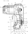
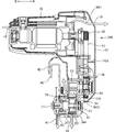
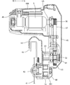
- FIG. 5 shows a side view of the first embodiment of the housing 40 of the circular saw section 4 when the tabletop cutting machine 1 shown in FIG. 4 is cut along the line VV.
- the housing 40 of the tabletop cutting machine 1 includes a saw cover 42 that covers a part of the outer periphery of the saw blade 41, and a spindle 43 that is connected to the saw cover 42 and serves as the rotation center of the saw blade 41.
- a gear case 44 that covers the motor 6 a main housing 45 that is connected to the gear case 44 and accommodates part of the transmission mechanism 5 described later, and a motor housing 46 that is connected to the main housing 45 and covers the motor 6. Composed.
- the spindle 43 is an example of an output shaft.
- a spring (not shown) is provided on the outer periphery of the swing shaft 32, and the circular saw portion 4 is urged by the spring so that the saw blade 41 is moved away from the base portion 2 (upward). It is located at the position swung upwards as shown in FIG. 1 by a stopper mechanism (not shown). The cutting process is performed by swinging the circular saw portion 4 downward with the swing shaft 32 as a fulcrum against the urging force of the spring. When the circular saw portion 4 is swung downward, the saw blade 41 enters a groove (not shown) provided in the turntable 22 and is swung by a stopper mechanism (not shown) in a state where a predetermined amount has entered. Stopped.
- the saw blade 41 is supported by the spindle 43 and is rotated coaxially and integrally with the spindle 43.
- the gear case 44 houses a first pulley 51 as a rotating member, a pulley shaft 52 as an intermediate shaft, and a second pulley 53.
- the gear case 44 is an example of a case.
- the first pulley 51 is a toothed pulley (timing pulley) in which a plurality of teeth are formed on the outer peripheral surface at a predetermined interval.
- the first pulley 51 is connected to the spindle 43 and coaxially and rotates integrally with the spindle 43.
- the pulley shaft 52 is disposed inside the gear case 44 so that the center thereof is parallel to the center axis of the spindle 43.
- a second pulley 53 is provided coaxially and integrally with the pulley shaft 52 on one end side of the pulley shaft 52 adjacent to the saw blade 41.
- the second pulley 53 is a toothed pulley (timing pulley) in which a plurality of teeth are formed at predetermined intervals on the outer peripheral surface. More specifically, the second pulley 53 has teeth (grooves) extending in the circumferential direction in parallel with the rotation axis (left and right direction) on the outer circumferential surface.
- first pulley 51 and the second pulley 53 are arranged so that the outer peripheral surfaces thereof face each other with a gap in the direction in which the side surface of the saw blade 41 extends.
- the first belt 54 is stretched between the two. More specifically, teeth (grooves) extending in a direction parallel to the rotation axis are formed on the first belt 54 side by side in the circumferential direction on the inner circumferential surface.
- the rotation of the second pulley 53 is transmitted to the first pulley 51 by the rotation of the first belt 54.
- the first belt 54 is a toothed belt such as a timing belt.
- the second pulley 53 is an example of a third rotating member
- the first belt 54 is an example of a second belt
- the first pulley 51 is an example of a fourth rotating member.
- the transmission mechanism formed by the second pulley 53, the first belt 54, and the first pulley 51 is an example of a second transmission mechanism.
- the gear case 44 is formed with a first opening 71 at a position on the outer peripheral surface facing the workpiece W placed on the base portion 2 and in the vicinity of the toothed surface of the first pulley 51. .
- the first opening 71 communicates the inside and the outside of the gear case 44 as an exhaust port.
- the first opening 71 has a shape and a size such that the cooling air discharged from the first opening 71 is directed to the workpiece W.
- the gear case 44 in which the first opening 71 is formed and the workpiece W define a working space.
- the spindle 43 is rotatably supported by a bearing holder 47 attached to the gear case 44 via a bearing 61, protrudes to the outside of the gear case 44, and is formed so that the rotation center of the saw blade 41 can be attached to the tip portion thereof.
- a second opening 72 is formed as an exhaust port on the surface of the bearing holder 47 facing the saw blade 41.
- the second opening 72 communicates the inside and the outside of the gear case 44.
- the second opening 72 has a shape and a size such that the cooling air discharged from the second opening 72 is directed to the saw blade 41.
- the second opening 72 is formed in an arc shape centering on the spindle 43 on the surface facing the saw blade 41 of the bearing holder 47.
- the second opening 72 faces the saw blade 41 of the bearing holder 47 so as to be positioned between the spindle 43 and the base 21 when the circular saw portion 4 is swung toward the base portion 2. Formed on the surface.
- the main housing 45 communicates with the gear case 44 through the communication space S ⁇ b> 1 and accommodates the third pulley 55 and the fourth pulley 56.
- the third pulley 55 is connected to the other end of the pulley shaft 52 at the same center as the pulley shaft 52 and rotates integrally with the pulley shaft 52.
- the pulley shaft 52 is supported by a bearing 62 so as to be rotatable with respect to the main housing 45.
- the fourth pulley 56 is connected coaxially with the output shaft 6A of the motor 6 and rotates integrally with the output shaft 6A. Further, the third pulley 55 and the fourth pulley 56 are arranged so that the outer peripheral surfaces thereof face each other in the direction in which the side surface of the saw blade 41 extends, and between the third pulley 55 and the fourth pulley 56.
- the second belt 57 is stretched.
- the second belt 57 is a toothed belt such as a timing belt.
- the first pulley 51, the pulley shaft 52, the second pulley 53, the first belt 54, the third pulley 55, the fourth pulley 56, and the second belt 57 are transmission mechanisms that transmit the output of the motor 6 to the saw blade 41. 5 is configured.
- each of the third pulley 55 and the fourth pulley 56 may be a V pulley formed such that a V groove extends in the circumferential direction on the cylindrical surface.
- the second belt 57 is a V belt.
- the output shaft 6A of the motor 6 is an example of a rotating shaft
- the fourth pulley 56 is an example of a first rotating member
- the second belt 57 is an example of a first belt
- the third pulley 55 is a second pulley. It is an example of a rotating member.
- the transmission mechanism formed by the fourth pulley 56, the second belt 57, and the third pulley 55 is an example of a first transmission mechanism.
- the communication space S1 is an example of an air inlet provided in the housing. Accordingly, the communication space S ⁇ b> 1 is located on one side of the gear case 44 near the main housing 45, and the second opening 72 is located on the other side of the gear case 44 near the saw blade 41.
- the motor housing 46 is formed in a cylindrical shape that accommodates the motor 6 and the cooling fan 7, and one end in the axial direction communicates with the main housing 45.
- the motor 6 is arranged such that the output shaft 6A extends toward the main housing 45, is parallel to the spindle 43 serving as the rotation shaft of the saw blade 41, and intersects with an extension line on the side surface of the saw blade 41.
- the cooling fan 7 is fixed to the output shaft 6A.
- the rotational force of the motor 6 is transmitted to the fourth pulley 56 that rotates integrally with the output shaft 6 ⁇ / b> A, and is transmitted to the transmission mechanism 5.
- the output shaft 6A is an example of a motor rotation shaft
- the cooling fan 7 is an example of a fan or a motor fan.
- a plurality of slit-shaped openings are formed as wind windows 48 at the other end of the motor housing 46 so that outside air can be introduced into the motor housing 46.
- a saw cover 49 (FIG. 1) having a shape covering the outer peripheral portion of the saw blade 41 protruding from the saw cover 42 is rotatably provided. As shown in FIG. 1, the saw cover 49 rotates to a position covering the outer periphery of the saw blade 41 at a portion protruding from the saw cover 42 when the circular saw portion 4 is swinging upward.
- the saw cover 49 is housed in the saw cover 42 by a link mechanism (not shown) in a state where the circular saw portion 4 is swinging downward, and the outer periphery of the saw blade 41 protruding from the saw cover 42 is exposed. To turn.
- the main housing 45 is integrally provided with a handle portion 8 located on an extension line of the side surface of the saw blade 41.
- the handle portion 8 is provided with a switch 9 for controlling the driving of the motor 6.
- the motor housing 46 is provided with a fixing mechanism (not shown) that fixes the movement of the circular saw portion 4 relative to the base portion 2 in a state where the circular saw portion 4 swings to the lowest position. By using the fixing mechanism, the tabletop cutting machine can be easily transported.
- the switch 9 provided on the handle portion 8 is operated to rotate the motor 6 and rotate the saw blade 41 around the spindle 43.
- the handle portion 8 is gripped, the circular saw portion 4 is pushed down against the biasing force of the spring, and the workpiece W is cut.
- the saw blade 41 enters the groove portion of the turntable 22 and the cutting force of the circular saw portion 4 is released when the workpiece W has been cut, the circular saw portion 4 is moved to the original upper limit position by the biasing force of the spring.
- the fourth pulley 56 rotates together with the rotation of the output shaft 6A, and the rotation of the fourth pulley 56 is transmitted to the third pulley 55 via the second belt 57, so that the third pulley 55 rotates.
- the second pulley 53 rotates with the rotation of the third pulley 55, and the rotation of the second pulley 53 is transmitted to the first pulley 51 via the first belt 54, so that the first pulley 51 rotates. Since the spindle 43 rotates with the rotation of the first pulley 51 and the saw blade 41 rotates, the workpiece W can be cut by the saw blade 41.
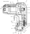
- the cooling fan 7 rotates along with the rotation of the motor 6, and outside air is taken into the motor housing 46 as cooling air from the wind window 48 along with the rotation of the cooling fan 7. Since the motor housing 46 and the main housing 45 communicate with each other, and the main housing 45 communicates with the gear case 44 via the communication space S1, the cooling air taken into the motor housing 46 cools the motor 6, Next, the main housing 45 is entered and cooled by sequentially passing by the fourth pulley 56, the second belt 57, and the third pulley 55 in the main housing 45.
- the cooling air enters the gear case 44 through the communication space S ⁇ b> 1, and sequentially passes by the second pulley 53, the first belt 54, and the first pulley 51 in the gear case 44, and then the first opening of the gear case 44. 71 and the second opening 72 of the bearing holder 47 are exhausted to the outside. At this time, the cooling air passes from the communication space S1 to the second opening 72, and escapes from one end side of the second pulley 53, the first belt 54, and the first pulley 51 to the other end side (right side to left side). That is, the cooling air passes through the space where the first belt 54 is stretched between the second pulley 53 and the first pulley 51.
- the cooling air flow path P is formed across the motor housing 46, the main housing 45, the communication space S 1, and the gear case 44 from the wind window 48 to the first opening 71 or the second opening 72. Is done. Since the first to fourth pulleys 51, 53, 55, 56 and the first and second belts 54, 57 constituting the transmission mechanism 5 are located inside the air passage P, the first to fourth pulleys are located. The pulleys 51, 53, 55, 56 and the first and second belts 54, 57 can be cooled by cooling air that directly hits them, and heat generated in these members by driving can be dissipated.
- the first pulley 51 and the first belt 54 are placed in the air path P and directly exposed to the cooling air, the heat generated in the transmission mechanism 5 by the operation of the tabletop cutting machine 1 is efficiently radiated. It is possible. Therefore, deterioration due to heat of components constituting the transmission mechanism 5 including the first pulley 51 and the first belt 54, which are the most heavily loaded in the transmission mechanism, can be suppressed, so that the life can be improved.
- the cooling air passes through all the members that rotate during the work, such as the motor 6 and the saw blade 41, and the entire power transmission path from the motor 6 to the saw blade 41 is cooled. be able to.
- Cooling air is exhausted to the outside from the first opening 71 of the gear case 44 and the second opening 72 of the bearing holder 47 adjacent to the saw blade 41. At this time, the cooling air exhausted from the second opening 72 hits the side surface of the saw blade 41 and changes the traveling direction. Further, the cooling air that tends to flow in the direction approaching the wind window 48 is regulated by the spindle 43. Therefore, most of the cooling air exhausted from the first opening 71 and the second opening 72 flows in a direction away from the wind window 48. Thereby, it is possible to effectively suppress the exhaust that has absorbed the heat generated in the transmission mechanism 5 from moving toward the wind window 48, and to suppress the circulation of the cooling air (exhaust).
- the chips generated by cutting the workpiece W approach the first opening 71 and the second opening 72
- the chips from the first opening 71 and the second opening 72 to the inside of the gear case 44 due to the momentum of exhaust. Can be prevented from entering.
- the opening area per one can be reduced, and the plurality of opening portions (the first opening 71 and the second opening 72) face in different directions. Since it comprised so, it can suppress that a chip
- first opening 71 and the second opening 72 are provided in the lower portion of the gear case 44, even if dust such as chips enters the gear case 44, dust accumulated in the lower portion in the gear case 44 due to gravity. Can be suitably discharged by exhausting air from the first opening 71 and the second opening 72. In particular, since the first opening 71 opens downward, it is easier to discharge dust. Further, before starting the work, the exhaust from the second opening 72 is guided by the side surface of the saw blade 41 and reaches the end portion (blade edge) of the saw blade 41. Therefore, since the exhaust gas can eliminate chips adhering to the saw blade 41 including the cutting edge, it is possible to suppress a decrease in cutting performance.
- the cooling air discharged from the first opening 71 and the second opening 72 is covered. Since the chips are blown off by hitting the processed member W, the visibility of the cut portion by the saw blade 41 can be improved. That is, the cooling air discharged from the first opening 71 and the second opening 72 can be used as a blower for chips. Further, the chips scattered in the air also move away from the wind window 48 due to the air flow away from the wind window 48, so that it is possible to prevent the chips from entering the motor housing 46.
- the communication space S ⁇ b> 1 that functions as an intake port and the second opening 72 that functions as an exhaust port are provided so as to be separated in a direction orthogonal to the axial direction of the spindle 43.
- the spindle 43, the first pulley 51, a part of the first belt 54, and the bearing 61 are arranged so as to be positioned between the communication space S ⁇ b> 1 and the second opening 72 in a direction orthogonal to the axial direction of the spindle 43. .
- the cooling air escapes from the second pulley 53 side of the first pulley 51 to the opposite side (vertical direction in the figure), so that the spindle 43, the first pulley 51, a part of the first belt 54, and the bearing 61 are removed. It can be cooled effectively.
- the communication space S1 functioning as an intake port and the second opening 72 functioning as an exhaust port are provided so as to be separated in a direction parallel to the axial direction of the spindle 43.
- the cooling air flows from one end side of the rotation shaft of the second pulley 53, the first belt 54 and the first pulley 51 to the other end side (from the right side to the left side), and from the second pulley 53 side of the first pulley 51.
- the spindle 43, the first pulley 51, the second pulley 53, the first belt 54, and the bearing 61 can be effectively cooled because they come out in the opposite direction (vertical direction in the figure). Further, the cooling air passes through a space where the first belt 54 is stretched between the first pulley 51 and the second pulley 53. In other words, the cooling air passes through the first belt 54 in a direction crossing the stretching direction of the first belt 54. Therefore, even if shavings are generated from the first belt 54 due to wear due to the work load and the shavings adhere to the second pulley 53 and the first pulley 51, the right to left so as to cross the first belt 54. Shavings can be eliminated by the cooling air flowing through.
- first pulley 51 and the second pulley 53 which are timing pulleys, are formed with grooves extending in the direction parallel to the rotation axis (left and right direction), so that the cooling air flows along the grooves.
- the dust adhering in the groove can be suitably eliminated.
- the wind window 48 for taking in the cooling air into the housing and the first opening 71 and the second opening 72 for discharging the cooling air from the gear case 44 are provided apart from each other, the first opening 71 and the second opening 72 are provided.
- the recirculation of the cooling air exhausted from the air is taken into the housing again through the air window 48 and passes through the air passage P is suppressed. Therefore, since the outside air that does not always include exhaust heat can be taken into the housing, the transmission mechanism 5 can be efficiently cooled.
- the gear occlusion is not used to transmit the rotation of the motor 6 to the saw blade 41, it is necessary to use the lubricating oil indispensable for the gear occlusion and to seal the gear case 44 for suppressing the leakage of the lubricating oil. And not. Therefore, the gear case 44 can be reduced in size, and an opening can be formed in the gear case 44 itself, so that the cooling air can be directly applied to the first pulley 51 integrated with the spindle 43. Efficiency can be improved.
- the output of the motor 6 is transmitted to the saw blade 41 using the belts 54 and 57 instead of the engagement of the gear, the volume of the transmission mechanism 5 occupying the housing is reduced and the transmission mechanism 5 is reduced in weight.
- the cooling air flow path P can be widely provided in the housing. Furthermore, since the meshing of the gear made of metal is eliminated, noise is reduced.
- the location of the first opening 71 in the gear case 44 can be provided in an appropriate location of the gear case 44 regardless of the above embodiment as long as the first pulley 51 can be cooled by cooling air. is there.
- the 1st opening 71 and the 2nd opening 72 were provided as a discharge port of cooling air, only any one may be sufficient.
- the bearing holder 47 is provided as a separate member from the gear case 44, but the bearing holder 47 may be provided integrally with the gear case 44.
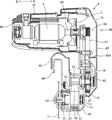
- FIG. 8 shows a housing of a tabletop cutting machine according to the second embodiment of the present invention.
- the same reference numerals are given to portions common to the embodiments described in FIGS. 1 to 7.
- the housing shown in FIG. 8 is different from the embodiment described in FIGS. 1 to 7 in that the first opening 71 and the second opening 72 are not provided, and a third opening 73 is newly formed.
- the third opening 73 is formed as an exhaust port on the surface of the gear case 44 facing the saw blade 41.
- the third opening 73 communicates the inside and the outside of the gear case 44.
- the third opening 73 is formed between the first pulley 51 and the second pulley 53 in the direction parallel to the side surface of the saw blade 41 on the outer peripheral surface of the gear case 44.
- the third opening 73 is defined inside the gear case 44 and is formed so as to face a space where the first belt 54 between the first pulley 51 and the second pulley 53 is stretched.
- the third opening 73 is provided at a position facing the communication space S ⁇ b> 1 so that the cooling air that has passed through the communication space S ⁇ b> 1 can reach the third opening 73 directly.
- the third opening 73 is formed in an arc shape centering on the spindle 43 on the surface of the bearing holder 47 facing the saw blade 41.
- the cooling air passes through the communication space S1, it passes from the right to the left through the space where the first belt 54 between the first pulley 51 and the second pulley 53 is stretched, and the third The air is exhausted from the opening 73 to the outside. That is, the air path P from the communication space S ⁇ b> 1 is formed so as to pass from the communication space S ⁇ b> 1 between the first pulley 51 and the second pulley 53 to the third opening 73.
- the communication space S1 and the third opening 73 are provided so as to be separated in a direction parallel to the axial direction of the spindle 43, and each of the communication space S1 and the third opening 73 is a pulley. They are arranged so as to be located between the central axis of the shaft 52 and the central axis of the spindle 43.
- the cooling air passing through the gear case 44 is formed to concentrate between the first pulley 51 and the second pulley 53. Therefore, even if shavings are generated from the first belt 54 due to wear due to the work load and the shavings adhere to the second pulley 53 and the first pulley 51, the right to left so as to cross the first belt 54.
- first pulley 51 and the second pulley 53 which are toothed pulleys, are formed with grooves extending in the direction parallel to the rotation axis (left and right direction), so that the cooling air flows along the grooves.
- the dust adhering to the inside of the grooves of the first pulley 51 and the second pulley 53 can be more suitably eliminated.
- the housing 140 has a shape that covers a saw cover 42 that covers a part of the outer periphery of the saw blade 41, and a spindle 43 that is connected to the saw cover 42 and serves as the rotation center of the saw blade 41.
- a fourth opening 74 is formed on the outer peripheral surface facing the saw blade 41 so as to communicate the inside and the outside of the gear case 144, and functions as an exhaust port.
- the fourth opening 74 is located between the first pulley 51 and the second pulley 53 on the outer peripheral surface of the gear case 144.
- the fourth opening 74 is formed in the gear case 144 at a position facing the space where the first belt 54 is stretched between the first pulley 51 and the second pulley 53. Further, the fourth opening 74 is provided at a position facing the communication space S ⁇ b> 1 so that the cooling air that has passed through the communication space S ⁇ b> 1 reaches the fourth opening 74 directly.
- the fourth opening 74 is formed in an arc shape centering on the spindle 43 on the surface of the gear case 144 facing the saw blade 41.
- the main housing 145 has a fifth opening 75 formed on the motor 6 side and a sixth opening 76 formed on the pulley shaft 52 side.
- a partition wall 145 ⁇ / b> A that protrudes inward is provided at a substantially intermediate position between the third pulley 55 and the fourth pulley 56 on the inner surface of the main housing 145 that faces the transmission mechanism 5.
- the partition wall 145A includes a motor cooling air passage W1 formed in the motor housing 46 by the rotation of the fan 7 and a transmission mechanism cooling air passage W2 formed in the gear case 144 in the main housing 145 independently of each other.
- the motor cooling air passage W1 and the transmission mechanism cooling air passage W2 are formed in such a size that they are prevented from crossing each other and the motor cooling air passage W1 and the transmission mechanism cooling air passage W2 are made independent of each other.
- each of the third pulley 155 and the fourth pulley 56 is a V pulley
- the second belt 57 is a toothed belt.
- the third pulley 155 includes a rotation shaft core 155A that is fixed coaxially to the pulley shaft 52, a cylindrical portion 155B on which the second belt 57 is suspended, and a cylindrical portion 155B that rotates.
- a plurality of wing portions 155C are formed between the shaft core 155A and the gap 155d in the circumferential direction.
- the cylindrical portion 155B has a V-groove extending in the circumferential direction on the surface, and at least one V-groove is formed side by side in the rotation axis direction.
- the plurality of wing portions 155C are radially formed so that each extends from the rotation axis 155A to the cylindrical portion 155B.
- a plurality of wing portions 155C are formed in the circumferential direction via gaps 155d.
- the plurality of wing portions 155C When the plurality of wing portions 155C are rotated around the rotating shaft core 155A, the plurality of wing portions 155C have a shape that functions as an axial fan, and generate wind that passes through the gap 155d and travels toward the second pulley 53.
- the number and specific shape of the wings 155C are appropriately set according to the strength of the cooling air generated by the third pulley 155 as an axial fan.
- the fourth pulley 56 rotates along with the rotation of the output shaft 6A, and the rotation of the fourth pulley 56 is transmitted to the third pulley 155 via the second belt 57, so that the third pulley 56 is rotated.
- Pulley 155 rotates.
- the second pulley 53 rotates with the rotation of the third pulley 155, and the rotation of the second pulley 53 is transmitted to the first pulley 51 via the first belt 54, so that the first pulley 51 rotates. Since the spindle 43 rotates with the rotation of the first pulley 51 and the saw blade 41 rotates, the workpiece W can be cut by the saw blade 41.
- the cooling fan 7 rotates with the rotation of the motor 6, so that outside air is taken into the motor housing 46 as cooling air from the wind window 48.
- the cooling air flows from the motor housing 46 into the main housing 145, but is prevented from moving toward the communication space S ⁇ b> 1 by the partition wall 145 ⁇ / b> A and is discharged to the outside of the housing 140 through the fifth opening 75. That is, a motor cooling air passage W ⁇ b> 1 extending from the wind window 48 to the fifth opening 75 is formed in the housing 140.
- the cooling air flowing through the air passage W1 cools the motor 6 located in the air passage W1, and the fourth pulley 56 and a part of the second belt 57.
- the third pulley 155 when the third pulley 155 rotates, it also functions as an axial fan and generates a wind toward the second pulley 53, so that outside air is taken in as cooling air from the sixth opening 76.
- the taken cooling air passes through the space 155d in the cylindrical portion 155B of the third pulley 155, passes through the space between the first and second pulleys 51 and 53, and passes through the fourth opening 74 to the outside of the housing 140. Discharged. That is, a transmission mechanism cooling air passage W2 including a part of the third pulley 155 and the first and second pulleys 51 and 53 is formed from the sixth opening 76.
- the cooling air flowing through the air passage W2 passes through the third pulley 155, the first and second pulleys 51 and 53, a part of the first belt 54, and the side of the bearing 61, and passes through the fourth opening 74 of the gear case 144. It is exhausted to the outside through.
- the third pulley 155 is more efficient from both the outer peripheral surface side and the inner peripheral surface side than when there is no gap 155c. Cools well. Further, since the third pulley 155 functions as an axial fan, the cross section in the traveling direction of the transmission mechanism cooling air passage W2 can be widened, a space having a cooling effect can be provided widely, and heat generation by driving in particular.
- the first, second and third pulleys 51, 53, 155 and the bearings 61, 62 having a large amount can be efficiently cooled.
- the first, second, and third pulleys 51, 53, and 155 and the bearings 61 and 62 to be cooled are examples of rotating members in the present invention.
- the motor cooling air passage W1 from the air window 48 toward the fifth opening 75 and the transmission mechanism cooling air passage W2 from the sixth opening 76 passing through the inside of the cylindrical portion 155B of the third pulley 155 toward the fourth opening 74 are provided. Are formed in the housing 140. Since the motor 6, the fourth pulley 56, and a part of the second belt 57 are located in the motor cooling air passage W1, these parts can be cooled by the cooling air directly exposed to the drive. The heat generated by can be efficiently radiated. On the other hand, a part of the second belt 57, the first to third pulleys 51, 53, 55, the first belt 54, and the bearings 61, 62 are located in the transmission mechanism cooling air passage W2. Since it is directly cooled by the cooling air that is taken in from the outside that is not heated by the exhaust heat of the motor 6, the heat generated in these members by driving can be efficiently radiated.
- the cooling air of any one of the air passages W 1 and W 2 passes through all members that operate during the work, such as the motor 6 and the saw blade 41, and the entire interior of the housing 140 is configured. Can be cooled.
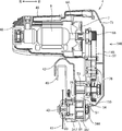
- the housing 240 of the tabletop cutting machine 1 according to the fourth embodiment will be described with reference to FIGS.
- the same components will be denoted by the same reference numerals, and detailed description thereof will be omitted.
- the configuration of the first pulley 251 and the position of the opening provided in the gear case 244 are different from the third embodiment. Since the other configuration is the same as that of the third embodiment, description of each component is omitted.
- the housing 240 of the tabletop cutting machine 1 includes a saw cover 42, a gear case 244 that is connected to the saw cover 42 and covers a spindle 43 that serves as a rotation center of the saw blade 41, and a gear case 244.
- the main housing 145 is connected to accommodate a part of the transmission mechanism 5, and the motor housing 46 is connected to the main housing 145 and covers the motor 6.
- a seventh opening 77 is formed in the gear case 244 on the outer peripheral surface facing the workpiece W placed on the base portion 2 and in the vicinity of the toothed surface of the first pulley 251.
- the seventh opening 77 serves as an exhaust port and allows communication between the inside and the outside of the gear case 244.
- the seventh opening 77 has a shape and a size such that the cooling air discharged from the seventh opening 77 is directed to the workpiece W.
- the bearing holder 247 is also formed with an eighth opening 78 that allows the gear case 244 to communicate with the outside via the bearing holder 247.
- the eighth opening 78 is formed on the surface of the bearing holder 247 that faces the saw blade 41.
- each of the first pulley 251 and the second pulley 53 is a timing pulley
- the first belt 54 is a toothed belt.
- the first pulley 251 includes a rotating shaft core 251A that is fixed coaxially to the spindle 43, a cylindrical portion 251B on which the first belt 54 is suspended, and a cylindrical portion 251B.
- a plurality of wings 251C are formed between the rotary shaft core 251A and the gap 251d in the circumferential direction.
- protrusions extending in the rotation axis direction are formed as teeth in the circumferential direction at intervals.
- the plurality of wing portions 251C are radially formed so that each extends from the rotation axis 251A to the cylindrical portion 251B.
- a plurality of wing portions 251C are formed in the circumferential direction via gaps 251d.
- the plurality of wing portions 251C When the plurality of wing portions 251C are rotated around the rotation axis 251A, the plurality of wing portions 251C have a shape that functions as an axial fan, and generate wind that passes through the gap 251d and travels toward the saw blade 41 side.
- the number and specific shape of the wings 155C are appropriately set according to the strength of the cooling air generated by the first pulley 251 as an axial fan.
- the fourth pulley 56 rotates along with the rotation of the output shaft 6A, and the rotation of the fourth pulley 56 is transmitted to the third pulley 55 via the second belt 57, so that the third pulley 56 rotates.
- the pulley 55 rotates.
- the second pulley 53 rotates with the rotation of the third pulley 55, and the rotation of the second pulley 53 is transmitted to the first pulley 251 via the first belt 54 and the first pulley 251 rotates. Since the spindle 43 rotates with the rotation of the first pulley 251 and the saw blade 41 rotates, the workpiece W can be cut by the saw blade 41.
- the cooling fan 7 rotates with the rotation of the motor 6, and the outside air is taken into the motor housing 46 as cooling air from the wind window 48 with the rotation of the cooling fan 7.
- the cooling air flows from the motor housing 46 into the main housing 45, but is prevented from proceeding toward the communication space S ⁇ b> 1 by the partition wall 145 ⁇ / b> A and is discharged to the outside of the housing 240 through the fifth opening 75. That is, a motor cooling air passage W11 extending from the wind window 48 to the fifth opening 75 is formed in the housing 240, and the motor 6, the fourth pulley 56, and a part of the second belt 57 are formed by the cooling air flowing through the air passage W1. And are cooled.
- the first pulley 251 also functions as an axial fan when rotated, the outside air is taken in as cooling air from the sixth opening 76, and the cooling air passes through the outer peripheral surface of the third pulley 55, and further communicates with the communication space. It passes through the inside of the cylindrical portion 251 ⁇ / b> B of the first pulley 251 through S ⁇ b> 1 and is discharged to the outside of the housing 240 through the seventh opening 77 or the eighth opening 78. That is, a transmission mechanism cooling air passage W12 including a part of the third pulley 55, the first pulley 251, and the second pulley 53 is formed from the sixth opening 76.
- the cooling air flowing through the air passage W12 passes through the second belt 57, the third pulley 55, the second pulley 53, the first pulley 251, a part of the first belt 54, the bearings 61 and 62, and the seventh opening 77. Alternatively, the air is exhausted to the outside through the eighth opening 78.
- the first pulley 251 can be efficiently cooled compared to the case without the gap 251c. Further, since the first pulley 251 functions as an axial fan, a cross section with respect to the traveling direction of the transmission mechanism cooling air passage W12 can be widened, and a space having a cooling effect can be widened. In particular, the first pulley 251 and the third pulley 55 and the bearings 61 and 62 that generate a large amount of heat generated by driving can be efficiently cooled.
- the motor cooling air passage W11 from the air window 48 toward the fifth opening 75 and the transmission mechanism cooling air passage W12 from the sixth opening 76 toward the seventh opening 77 or the eighth opening 78 are formed in the housing 240. Is done. Since the motor 6, the fourth pulley 56, and a part of the second belt 57 are located in the motor cooling air passage W11, these parts can be cooled by the cooling air directly exposed to the drive. The heat generated by can be efficiently radiated. On the other hand, a part of the second belt 57, the first to third pulleys 251, 53, 55, the first belt 54, and the bearings 61, 62 are located in the transmission mechanism cooling air passage W12. Since it is directly cooled by the cooling air that is taken in from the outside that is not heated by the exhaust heat of the motor 6, the heat generated in these members by driving can be efficiently radiated.
- any of the cooling air passes through all members that rotate during the operation, such as the motor 6 and the saw blade 41, and the inside of the housing 240 can be cooled as a whole.
- a desktop cutting machine housing 340 according to a fifth embodiment of the present invention will be described with reference to FIGS. 15 and 16.
- the third and fourth embodiments are different from the third and fourth embodiments in that the pulley 251 that also functions as the axial fan used in the fourth embodiment is used as the first pulley, and the third pulley is the third pulley.
- a pulley 155 that also functions as the axial fan used in the embodiment is used.
- the gear case 344 is positioned on the outer peripheral surface facing the saw blade 41 at an opening 79 facing the intermediate position between the first pulley 251 and the second pulley 53, and on the opposite side of the spindle 43 from the opening 79.
- An opening 80 formed in the bearing holder 347 facing the saw blade 41 and an opening 81 on the surface facing the gear case 344 of the cylindrical portion 251B of the first pulley 251 are formed.
- the openings 79, 80, and 81 function as cooling air exhaust ports when the motor 6 is driven.
- the third pulley 155 when the third pulley 155 rotates, it also functions as an axial fan and generates a wind toward the second pulley 53, so that outside air is taken in as cooling air from the sixth opening 76.
- the taken cooling air passes through the space 155d in the cylindrical portion 155B of the third pulley 155, passes through the space between the first and second pulleys 251 and 53, and opens in the housing 340 through the openings 79, 80, and 81. It is discharged outside. That is, the transmission mechanism cooling air passage W22 including the third pulley 155, the second pulley 53, and the first pulley 251 is formed from the sixth opening 76.
- the cooling air flowing through the air passage W22 passes through the third pulley 155, the second pulley 53, the first pulley 251, the first belt 54, and the bearings 61 and 62, and passes through the openings 79, 80, and 81. Exhausted outside.
- the third pulley 155 is more efficient from both the outer peripheral surface side and the inner peripheral surface side than when there is no gap 155c. Cools well. Further, since the third pulley 155 functions as an axial fan, the cross section in the traveling direction of the transmission mechanism cooling air passage W22 can be widened, a space having a cooling effect can be provided large, and heat generation by driving in particular. The first, second and third pulleys 251, 53 and 155 and the bearings 61 and 62 having a large amount can be efficiently cooled.
- the first pulley 251 and the third pulley 155 function as an axial fan that generates cooling air that is directed toward the saw blade 41 in conjunction with each other. That is, in the transmission mechanism cooling air passage W22, since the two fans cooperate to generate cooling air, the air volume can be increased, and the cooling effect of the first pulley 251 and the third pulley 155 and the bearings 61 and 62 is enhanced. It is possible to prevent deterioration of these parts due to heat.
- the housing 440 of the sixth embodiment removes the cooling fan 7 from the housing 40 of the first embodiment, uses a pulley 251 that functions as an axial fan as a first pulley, and a shaft as a third pulley. A pulley 155 that functions as a flow fan is used.
- the motor housing 446 of the housing 440 is formed smaller than the motor housing 46 by the amount that the cooling fan is not provided.
- the first pulley 251 and the third pulley 155 are rotated by the transmission mechanism 5 to generate a wind toward the saw blade 41 side. Since no opening is formed in the main housing 45, outside air is introduced into the motor housing 446 as cooling air from the wind window 48, and cooling air flows toward the gear case 44 through the motor housing 446 and the main housing 45. The cooling air flows in the cylindrical portion 155 B of the third pulley 155 and the cylindrical portion 251 B of the first pulley 251, and is discharged to the outside of the housing 40 through the opening 71.
- the output shaft 6A of the motor 6 can be shortened, and as a result, the length of the saw blade 41 of the motor housing 446 in the rotation axis direction can be shortened. Accordingly, since the housing 440 itself can be made compact, the tilt angle range of the tabletop cutting machine 1 can be widened, and the operability of the tabletop cutting machine 1 can be improved.
- FIG. 18 is a sectional view of a disc grinder 500 to which the present invention is applied.
- a disc grinder 500 shown in FIG. 18 has a pulley 503 attached to an output shaft 502 on which a disc 501 as a tip tool is attached, instead of a final reduction portion formed by meshing gears that have been conventionally attached.
- the disc 501 is rotated by a belt drive of a pulley 505 mechanically connected to the output shaft of the motor 504.
- the pulleys 503 and 505 have a plurality of wings formed around the rotation axis within the cylindrical portion around which the belt is suspended, and when the pulleys rotate, the pulleys As well as an axial fan.
- the housing 507 is an outer peripheral surface facing the disk 501 and formed in the vicinity of the pulleys 503 and 505, and openings formed on the opposite side of the outer peripheral surface facing the disk 501. 511.
- an air passage W3 having the opening 511 as an intake port and the openings 508, 509 and 510 as an exhaust port is formed in the housing 507.
- An output shaft 502 that rotates at high speed, a bearing 506 that rotatably supports the output shaft 502, and pulleys 503 and 505 are taken into the air passage W3 and directly cooled. Therefore, the power transmission mechanism from the motor 504 to the disk 501 can be reduced in size, and each component can be efficiently cooled to prevent deterioration of the component due to heat.
- the present invention is not limited to a tabletop cutting machine and a disk grinder, and the rotation of a motor is output via a transmission mechanism.
- the present invention can be applied to an appropriate power tool that is transmitted to a shaft and can be operated by a tip tool.
Landscapes
- Engineering & Computer Science (AREA)
- Mechanical Engineering (AREA)
- Life Sciences & Earth Sciences (AREA)
- Wood Science & Technology (AREA)
- Forests & Forestry (AREA)
- Sawing (AREA)
- Grinding-Machine Dressing And Accessory Apparatuses (AREA)
Abstract
ギヤケースに収容された部品の冷却を容易とする動力工具を提供する。動力工具1は、モータ6と、モータ6により回転されて冷却風を生じるファン7と、モータ6及びファン7を収容して冷却風の風路Pを画定するハウジング42、44、45と、先端工具41が着脱可能であってモータ6により回転される出力軸43と、モータ6の回転を出力軸43に伝達する伝達機構5とを有する。伝達機構5は、出力軸43と一体回転する回転部材51を有し、回転部材51は風路P内に配置されている。
Description
本発明は、動力工具に関する。
卓上丸鋸等の動力工具では、モータから鋸刃への動力伝達機構の一部として、複数の金属製のギヤ同士の噛み合わせからなる最終減速部が、鋸刃の回転軸の直前に取り付けられている。この最終減速部は、ギヤケースに収容され、グリス等の潤滑油の漏れを抑制するためにギヤケースを密封する構造をとっている。
上記構成の動力工具では、ギヤケースが密封されているため、ギヤ同士の噛み合いによって発生する熱がギヤケース内にこもり、温度上昇による部品の劣化及び損傷を促進させる可能性があった。また、ギヤケースが密閉されているため、内部に収容されて発熱するギヤ等の部品を風に直接晒して冷却することができず、ギヤケース内に収容された部材の冷却・放熱が困難な構造となっていた。
本発明は、斯かる実情に鑑み、ギヤケース内に収容された部品の冷却を容易とする動力工具を提供しようとするものである。
本発明の動力工具は、モータと、前記モータにより回転されて冷却風を生じるファンと、前記モータ及び前記ファンを収容して前記冷却風の風路を画定するハウジングと、先端工具が着脱可能であって前記モータにより回転される出力軸と、前記モータの回転を前記出力軸に伝達する伝達機構と、を有し、前記伝達機構は、前記出力軸と一体回転する回転部材を有し、前記回転部材は前記風路内に配置されている。
上記構成により、回転部材に冷却風が直接当たって回転部材を冷却するので、回転部材の放熱を効率良く行うことができ、回転部材の劣化を抑制可能である。
好ましくは、前記ハウジングは、前記回転部材を収容するケースを有し、前記ケースは、前記冷却風を前記ケースの内部に導入する吸気口と、前記冷却風を前記ケースの外部に排気する排気口とを有し、前記吸気口と前記排気口との間に形成される空間は、前記風路に含まれ、当該空間に前記回転部材が配置されている。
好ましくは、前記回転部材はプーリであり、前記伝達機構は、前記モータの回転を前記プーリに伝達するベルトを有する。当該構成により、出力軸の駆動に対する潤滑油の注油を低減でき、ケースからの潤滑油漏れを抑制することができる。
好ましくは、前記プーリは歯付プーリであり、前記ベルトは歯付ベルトである。当該構成により、歯付きベルトは歯付きプーリに確実に係合してモータの回転を歯付きプーリに伝える。従って、モータの回転を確実に出力軸に伝達することができる。
好ましくは、前記伝達機構は、さらに、前記モータと同期して回転する第1プーリと、前記ハウジング内に設けられた中間軸と、各々が前記中間軸を中心に回転する第2及び第3プーリとを有し、前記ベルトは、前記第1プーリと前記第2プーリとに懸架される第1ベルトと、前記第3プーリと前記回転部材とに懸架される第2ベルトとを有し、前記第1から第3プーリと前記第1及び第2ベルトとは、前記風路内に配置される。当該構成により、全てのプーリ及びベルトを冷却風により冷却することができる。
好ましくは、前記排気口は、前記ケースの前記先端工具側に形成されて、前記冷却風は、前記先端工具に向けて排気される。当該構成により、排気された冷却風が先端工具に沿って被加工部材に当たるので、排気された冷却風は切粉のブロアとして機能し、作業時の視認性を向上させる。
好ましくは、前記先端工具によって加工される被加工部材と前記ケースとの間に、作業空間が画定され、前記排気口は、前記ケースの前記作業空間側に形成されて、前記冷却風は、前記作業空間に向けて排気される。当該構成により、排気された冷却風によって作業空間内に風が生じて切粉のブロアとして機能するので、作業時の視認性を向上させる。
好ましくは、前記吸気口は、前記ハウジング内の空間に開口され、前記ハウジングは、風窓を有し、前記風路は、前記風窓から前記吸気口を経て前記排気口に連通するように構成され、前記風窓は、前記出力軸に対し前記排気口とは反対側に設けられている。当該構成により、排気され排熱により温められた冷却風が、風窓より再びハウジング内に導入されてハウジング内を循環することを防止できる。
好ましくは、前記回転部材の回転軸に平行な方向において、前記吸気口は前記ケースの一方側に設けられ、前記排気口は前記ケースの他方側に設けられる。
好ましくは、前記回転部材の回転軸に平行な方向、または直交する方向において、前記回転部材は、前記排気口と前記吸気口との間に位置する。
さらに、本発明の動力工具は(請求項11、出願時には削除します。以下、同じ)、回転軸を有するモータと、前記モータにより回転されて冷却風を発生させるファンと、前記モータ及び前記ファンを収容して前記冷却風の風路を画定するハウジングと、先端工具が着脱可能であって前記モータにより回転される出力軸と、前記ハウジング内に設けられて回転可能な中間軸と、前記モータの回転を前記中間軸に伝達する第1伝達機構と、前記中間軸の回転を前記出力軸に伝達する第2伝達機構とを有し、前記第1伝達機構の中間軸側及び前記第2伝達機構の出力軸側が前記風路内に配置されて前記冷却風に晒される。
上記構成により、先端工具の作業領域で発生する熱が、先端工具及び出力軸を介して第2伝達機構に伝達した場合であっても、当該部分が冷却風によって冷却されるので、当該部分の寿命を延ばすことができる。
好ましくは、前記第1伝達機構は、前記回転軸と一体的に回転する第1回転部材と、前記中間軸と一体的に設けられて前記第1回転部材の回転に伴い回転される第2回転部材と、前記第1回転部材と前記第2回転部材との間に張架される第1ベルトとを有し、前記第2伝達機構は、前記中間軸と一体的に回転する第3回転部材と、前記出力軸と一体的に設けられて前記第3回転部材の回転に伴い回転される第4回転部材と、前記第3回転部材と前記第4回転部材との間に張架される第2ベルトとを有し、前記第2回転部材及び第4回転部材が前記風路内に配置される。
上記構成により、モータの回転により発熱量の多い第2回転部材及び第4回転部材を冷却できるので、第2回転部材及び第4回転部材の劣化を抑制できる。
好ましくは、前記ハウジングは、前記中間軸及び前記第2伝達機構を収容するケースを有し、前記ケースは、前記冷却風を前記ケースの内部に導入する吸気口と、前記冷却風を前記ケースの外部に排気する排気口とを有し、前記風路は、前記ファンの回転により前記吸気口から前記排気口までに流れる前記冷却風によって形成され、前記風路に前記第2回転部材及び第4回転部材が位置する。
上記構成により、ケース内で熱せられた空気を排気口から排出できるので、第2伝達機構を効率良く冷却できると共に、ケースによる防塵性を確保できる。
好ましくは、前記ファンは、前記回転軸に設けられ、前記ハウジングは風窓を有し、前記風路は、前記ファンの回転により前記風窓から前記吸気口に流れる前記冷却風によって形成され、前記風路に前記モータが位置する。
上記構成により、モータの回転軸に取り付けられたファンが発生させる風を利用することで、モータを優先的に冷却しつつ第1及び第2伝達機構を冷却できる。
好ましくは、前記ファンは、前記中間軸及び前記出力軸の少なくとも一方に設けられている。
上記構成により、中間軸にファンを設ける場合、中間軸付近に強力な冷却風が生成されて、中間軸付近の第1及び第2伝達機構の部品を効果的に冷却できる。また、出力軸にファンを設ける場合、出力軸付近に強力な冷却風が生成され、出力軸付近の第2伝達機構の部品を効果的に冷却できる。また、中間軸及び出力軸の両方にファンを設ける場合はより効果的に第1及び第2伝達機構を冷却できる。特に、第3回転部材の冷却効果を高くできる。さらに、2つのファンの駆動によりハウジング内に発生させる風の風量が増加するので冷却効果が向上する。
好ましくは、前記第1、第2、第3及び第4回転部材はそれぞれプーリからなり、前記第2回転部材及び第4回転部材のうちの少なくとも一方は、プーリの円筒部と回転軸との間で円周方向に空隙を介して形成された複数の羽部を有し、前記複数の羽部は回転されると前記ファンとして機能する。
上記構成により、第2回転部材及び第4回転部材の少なくとも一方がファンとして機能して冷却風を発生させるため、ハウジング内の部品の個数を減らしてハウジングの小型化を図ることができる。
好ましくは、前記第3及び第4回転部材は歯付プーリであり、前記第2ベルトは歯付ベルトである。上記構成により、歯付きプーリを回転させると、プーリに設けられた複数の羽の回転によって生成された冷却風により、モータを冷却できる。従って、モータの回転軸へのファンの取付が不要となり、モータハウジングの小型化を図ることができる。
好ましくは、前記ハウジングは、前記モータを収容するモータハウジングと、前記モータハウジングを外部に連通させる風窓をさらに有し、前記風路は、前記ファンの回転により前記風窓から前記モータハウジング内を流れる前記冷却風によって形成され、前記風路に前記モータが位置する。
上記構成により、モータの回転軸にファンを設けずともモータ冷却用の冷却風を生成できるので、モータハウジングの小型化を図ることができる。
好ましくは、前記風路は、前記ファンの回転により前記風窓から前記モータハウジング内を経て前記排気口に連通するように形成され、前記風窓は、前記出力軸に対し前記排気口とは反対側に設けられている。
上記構成により、モータの排熱により温められた冷却風が風窓より再びハウジング内に導入されてハウジング内を循環することを防止できる。
好ましくは、前記排気口は、前記ハウジングの前記先端工具側に形成されて、前記冷却風は、前記先端工具に向けて排気される。
上記構成により、排気された冷却風が先端工具に沿って被加工部材に当たるので、排気された冷却風は切粉のブロアとして機能し、作業時の視認性を向上させる。
好ましくは、前記先端工具によって加工される被加工部材と前記ケースとの間に作業空間が画定され、前記排気口は、前記ケースの前記作業空間側に形成されて、前記冷却風は、前記作業空間に向けて排気される。
上記構成により、排気された冷却風によって作業空間内に風が生じて切粉のブロアとして機能するので、作業時の視認性を向上させる。
好ましくは、被加工部材を載置可能な載置面を有するベース部と、前記ハウジングを前記載置面に対し接近又は離間可能に揺動可能に支持する支持部と、前記載置面内に延びる傾動軸を中心に、前記ハウジングを前記載置面に対し傾動可能に支持する傾斜機構とを有し、前記出力軸は前記傾動軸と直交する。
上記構成により、モータの回転軸にファンを取り付けないので、モータを収容するモータハウジングを小型にできる。従って、ベースの載置面に対しハウジングを傾動させるときの範囲を広く確保でき、動力工具の切断能力が向上する。
好ましくは、前記ファンは、前記モータの回転軸に取り付けられるモータファンをさらに含む。上記構成により、ハウジング内に複数のファンが設けられることによって、ファン近傍に位置する冷却対象を強い流れの冷却風によって冷却することができる。従って、第1及び第2伝達機構とモータとの効果的な冷却を図ることができる。
好ましくは、前記ファンは、前記モータの回転軸に取り付けられるモータファンをさらに有し、前記風路は、前記モータファンの回転により前記風窓から前記モータハウジング内を流れる冷却風によって形成されて前記モータを冷却するモータ冷却風路と、前記吸気口から前記排気口に流れる冷却風によって形成されて前記第2回転部材及び前記第4回転部材を冷却する伝達機構冷却風路とを有し、前記モータ冷却風路と前記伝達機構冷却風路とは互いに独立している。
上記構成により、第1及び第2伝達機構とモータとをそれぞれ異なる冷却風で冷却するので、モータにより熱せられた空気が伝達機構に行かず、伝達機構の冷却をより効果的に行うことができる。
好ましくは、前記出力軸に平行な方向に関して、前記吸気口は前記ケースの一方側に設けられ、前記排気口は前記ケースの他方側に設けられる。
好ましくは、第1ベルト及び第2ベルトは前記風路内に配置される。上記構成により、第1及び第2伝達機構全体が風路に配置されるので、第1及び第2伝達機構を効率良く冷却できる。
本発明の動力工具によれば、伝達機構を放熱させることができると共に、ハウジング内への切粉の浸入を防止することができる。
本発明の動力工具としての第1の実施の形態である卓上切断機を図面を参照して説明する。図1から図4に示されるように、卓上切断機1は、ベース部2と、ホルダ3と、丸鋸部4とから主に構成される。丸鋸部4には円盤状の鋸刃41が先端工具として装着され、丸鋸部4は、ベース部2に対して鋸刃41の側面に直交する方向に傾動可能に、さらに、ベース部2に対して丸鋸部4が接近離反する方向に揺動可能に構成されている。
ベース部2は、床面等に載置可能なベース21と、ベース21上に担持されたターンテーブル22と、ベース21に設けられたフェンス23とから主に構成される。ターンテーブル22の上面は、ベース21の上面とほぼ面一であり、ターンテーブル22は、上面に直交する回動軸を中心に回動可能にベース21と連結されている。作業時には、ベース21及びターンテーブル22に被加工部材Wが載置される。ターンテーブル22とベース21には、丸鋸部4が下降したときに鋸刃41の進入を許容する図示せぬ溝部が形成されている。なお、ベース21及びターンテーブル22は載置面の一例である。
フェンス23は、図3を参照すると、右フェンス23Aと左フェンス23Bとを有し、それぞれのフェンスは、ベース21の上面とほぼ直交する押さえ面23aを備える。被加工部材Wを切断加工するときには、フェンス23の押さえ面23aに被加工部材Wの一面が当接される。
ターンテーブル22の前部には、ターンテーブル22の回動操作および回動位置固定操作を行うための操作部24が設けられている。ターンテーブル22の後部には、傾動軸25と、突出部26とが設けられている。傾動軸25は、その中心軸がターンテーブル22の上面と一致するように前後方向に延びている。突出部26は、上方に突出しており、傾動軸25の中心軸を中心として円弧状に形成された長穴26a(図3)を有する。
ホルダ3は、支持部として、ターンテーブル22の後部において上方に立設しており、ホルダ3の下部は傾動軸25の周りに回動可能に設けられている。よって、ホルダ3は、ターンテーブル22に対して左右方向に傾動可能である。ホルダ3には上述した長穴26aと一致する位置に螺合穴3aが形成されており、螺合穴3aにはクランプレバー31が螺合する。具体的には、クランプレバー31のねじ部が長穴26aを貫通して螺合穴3aに螺合する。クランプレバー31を解除方向に操作することで、クランプレバー31の突出部26の面に対する押圧力が解除されのるで、ホルダ3は傾動軸25の回りを長穴26aの円弧長さ範囲で傾動できる。一方、クランプレバー31を固定方向に操作することで、クランプレバー31の突出部26の面に対し押圧力が付与されるので、ホルダ3は、所望の傾斜角度にて突出部26に対し固定され、故にターンテーブル22に対して固定される。なお、上記構成は傾斜機構の一例である。
ホルダ3のベース部側側面部分には傾斜時の位置決め手段である図示せぬ2個のストッパが設けられ、ターンテーブル22上面には図示せぬ2本のストッパボルトがストッパの移動軌跡上に位置してねじ止めされている。傾動軸25を中心としてターンテーブル22に対してホルダ3を傾斜させると、所定の傾斜角度でストッパがストッパボルトの各々の頭部に当接し、丸鋸部4の傾動位置が位置決めされる。一方のストッパボルトは、ホルダ3が左方向に45度の位置に傾斜したときに一方のストッパに係合するように設けられている。また、他方のストッパボルトは、ホルダ3が右方向に45度の位置に傾斜したときに他方のストッパに係合するように設けられている。また、ホルダ3の上端部分には、鋸刃41の側面と直交する方向に延びる揺動軸32が設けられている。なお、丸鋸部4の傾動範囲は、丸鋸部4の傾動方向における長さに依存し、丸鋸部4の傾動方向における長さが短ければ、その分傾動範囲を広くとることができる。
丸鋸部4は、揺動軸32を中心としてベース部方向、反ベース部方向に揺動可能に設けられている。図4は、揺動軸32を中心として丸鋸部4をベース部2に向けて揺動させて被加工部材Wの切断を開始したときの卓上切断機1の側面図を示す。また、図5に、図4に示す卓上切断機1を線分V-Vについて切断したときの丸鋸部4のハウジング40の第1の実施の形態の側面図を示す。
図5に示されるように、卓上切断機1のハウジング40は、鋸刃41の一部外周を覆う形状をしたソーカバー42と、ソーカバー42に連結されて、鋸刃41の回転中心となるスピンドル43を覆う形状をしたギヤケース44と、ギヤケース44と連結して後述する伝達機構5の一部を収容するメインハウジング45と、メインハウジング45と連結されてモータ6を覆う形状をしたモータハウジング46とから構成される。メインハウジング45が揺動軸32を軸として揺動することで、丸鋸部4が揺動する。なお、スピンドル43は出力軸の一例である。
揺動軸32外周にはスプリング(不図示)が設けられ、スプリングによって丸鋸部4は、ベース部2から鋸刃41が離れる方向(上方)に揺動するよう付勢されており、通常時には図示しないストッパ機構によって図1に示す最も上方に揺動した場所に位置する。切断加工は、丸鋸部4をスプリングの付勢力に抗して揺動軸32を支点に下方に揺動させることにより行なわれる。なお、丸鋸部4を下方に揺動させると、鋸刃41はターンテーブル22に設けられた溝部(不図示)内に侵入し、所定量侵入した状態で図示せぬストッパ機構によって揺動が停止される。
図5に示されるように、ソーカバー42において、鋸刃41は、スピンドル43に支持されてスピンドル43と同軸中心に且つ一体的に回転される。
図6に示されるように、ギヤケース44は、回転部材としての第1プーリ51、中間軸としてのプーリ軸52、第2プーリ53を収容する。ギヤケース44は、ケースの一例である。第1プーリ51は、外周面に複数の歯が所定間隔で形成されている歯付プーリ(タイミングプーリ)であり、スピンドル43と同軸中心に接続されてスピンドル43と一体的に回転する。プーリ軸52は、ギヤケース44の内部で、中心がスピンドル43の中心軸と平行となるように配設される。プーリ軸52の鋸刃41に近接する一端部側には、第2プーリ53がプーリ軸52と同軸中心に且つ一体的に設けられている。第2プーリ53は、外周面に複数の歯が所定間隔で形成されている歯付プーリ(タイミングプーリ)である。より詳しくは、第2プーリ53には、外周面にその回転軸と平行(左右方向)に延びる歯(溝)が周方向に並んで形成されている。
さらに、第1プーリ51と第2プーリ53とは、鋸刃41の側面が延在する方向において間隔を開けて互いに外周面が対向するように配置され、第1プーリ51と第2プーリ53との間には、第1ベルト54が張設されている。より詳しくは、第1ベルト54にはその周回軸と平行な方向に延びる歯(溝)が内周面において周方向に並んで形成されている。第1ベルト54の周回によって、第2プーリ53の回転が第1プーリ51に伝達される。本実施の形態において、第1ベルト54は、タイミングベルトなどの歯付ベルトからなる。なお、第2プーリ53は第3回転部材の一例であり、第1ベルト54は第2ベルトの一例であり、第1プーリ51は第4回転部材の一例である。また、第2プーリ53、第1ベルト54及び第1プーリ51によって形成される伝達機構は第2伝達機構の一例である。
また、ギヤケース44には、ベース部2に載置される被加工部材Wと対向する外周面であって、第1プーリ51の歯付面と近接する箇所に、第1開口71が形成される。第1開口71は、排気口として、ギヤケース44の内部と外部とを連通させる。第1開口71は、第1開口71から排出された冷却風が被加工部材Wへ向かうような形状及び大きさを有している。さらに、鋸刃41の切断作業中は、第1開口71が形成されたギヤケース44と被加工部材Wとは、作業空間を画定する。
さらに、スピンドル43は、ギヤケース44に取り付けられたベアリングホルダ47にベアリング61を介して回転可能に支持されて、ギヤケース44の外部に突出し、その先端部に鋸刃41の回転中心が装着可能に形成されている。また、ベアリングホルダ47の鋸刃41と対向する面には、第2開口72が排気口として形成される。第2開口72は、ギヤケース44の内部と外部とを連通させる。第2開口72は、第2開口72から排出された冷却風が鋸刃41へ向かうような形状及び大きさを有している。例えば、第2開口72は、図2に示されるように、ベアリングホルダ47の鋸刃41と対向する面において、スピンドル43を中心とする円弧状に形成される。また、第2開口72は、丸鋸部4をベース部2に向けて揺動させたときに、スピンドル43とベース21との間に位置するように、ベアリングホルダ47の鋸刃41と対向する面に形成されている。
図5及び図6に示されるように、メインハウジング45は、連通空間S1を介して内部がギヤケース44と連通し、第3プーリ55及び第4プーリ56を収容する。第3プーリ55は、プーリ軸52の他端部側にプーリ軸52と同軸中心に接続されてプーリ軸52と一体的に回転する。また、プーリ軸52は、ベアリング62によってメインハウジング45に対して回転自在に支持されている。
第4プーリ56は、モータ6の出力軸6Aと同軸中心に接続されて出力軸6Aと一体的に回転する。また、第3プーリ55と第4プーリ56とは、鋸刃41の側面が延在する方向において外周面が互いに対向するように配置され、第3プーリ55と第4プーリ56との間には、第2ベルト57が張設される。第2ベルト57は、タイミングベルトなどの歯付ベルトからなる。そして、第1プーリ51、プーリ軸52、第2プーリ53、第1ベルト54、第3プーリ55、第4プーリ56、第2ベルト57は、モータ6の出力を鋸刃41に伝達する伝達機構5を構成する。
例えば、第3プーリ55及び第4プーリ56は、それぞれ円筒面においてV溝が円周方向に延びるように形成されたVプーリを用いることができる。この場合、第2ベルト57は、Vベルトからなる。なお、モータ6の出力軸6Aは回転軸の一例であり、第4プーリ56は第1回転部材の一例であり、第2ベルト57は第1ベルトの一例であり、第3プーリ55は第2回転部材の一例である。また、第4プーリ56、第2ベルト57及び第3プーリ55によって形成される伝達機構は第1伝達機構の一例である。さらに、連通空間S1は、ハウジングに設けられる吸気口の一例である。従って、連通空間S1は、メインハウジング45に近いギヤケース44の一方側に位置し、第2開口72は鋸刃41に近いギヤケース44の他方側に位置する。
モータハウジング46は、モータ6と冷却ファン7とを収容する円筒形状に形成され、軸方向の一端部がメインハウジング45と連通する。モータ6は、出力軸6Aが、メインハウジング45に向けて延びると共に、鋸刃41の回転軸となるスピンドル43と平行に、且つ鋸刃41側面の延長線と交差するように配置されている。冷却ファン7は、出力軸6Aに固定されている。モータ6の回転力は、出力軸6Aと一体的に回転する第4プーリ56に伝達され、伝達機構5に伝達される。なお、出力軸6Aはモータの回転軸の一例であり、冷却ファン7はファン又はモータファンの一例である。
また、モータハウジング46の他端部には、複数のスリット状の開口が風窓48として形成され、外気をモータハウジング46の内部に導入可能とする。
さらに、ソーカバー42内には、ソーカバー42より突出する鋸刃41の外周部分を覆う形状をした鋸カバー49(図1)が回動可能に設けられている。鋸カバー49は、図1に示されるように、丸鋸部4が上方に揺動している状態では、ソーカバー42より突出する部分の鋸刃41外周を覆う位置に回動する。一方、鋸カバー49は、丸鋸部4が下方に揺動している状態では図示せぬリンク機構によってソーカバー42内に収納され、ソーカバー42より突出する部分の鋸刃41外周が露出される位置に回動する。
メインハウジング45には、鋸刃41側面の延長線上に位置するハンドル部8が一体的に設けられている。そして、ハンドル部8には、モータ6の駆動を制御するスイッチ9が設けられている。ハンドル部8を鋸刃41側面の延長線上に設けることにより、切断加工時(揺動時)に鋸刃41を介して丸鋸部4に作用する反力を、丸鋸部4に傾き等を生じさせることなく受けとめることができる。また、モータハウジング46には丸鋸部4が最下方に揺動した状態でベース部2に対する丸鋸部4の移動を固定する図示しない固定機構が設けられている。固定機構を用いることで卓上切断機の運搬が容易となる。
次に、上記卓上切断機1の動作について説明する。被加工部材Wを切断するには、ハンドル部8に設けたスイッチ9を操作してモータ6を回転させ、スピンドル43を中心に鋸刃41を回転させる。この状態で、ハンドル部8を握りスプリングの付勢力に抗して丸鋸部4を押し下げ、被加工部材Wを切断する。鋸刃41がターンテーブル22の溝部内へ侵入し被加工部材Wの切断が完了したときに丸鋸部4への押し下げ力を解除すると、丸鋸部4はスプリングの付勢力によって元の上限位置に復帰する。
さらに、卓上切断機1の動作中の、丸鋸部4の動作について詳細に説明する。モータ6が回転すると、出力軸6Aの回転と共に第4プーリ56が回転し、第4プーリ56の回転が第2ベルト57を介して第3プーリ55に伝達されて第3プーリ55が回転する。第3プーリ55の回転と共に第2プーリ53が回転し、第2プーリ53の回転は、第1ベルト54を介して第1プーリ51に伝達されて第1プーリ51が回転する。第1プーリ51の回転と共にスピンドル43が回転して鋸刃41が回転するので、鋸刃41による被加工部材Wの切断が可能となる。
このとき、図7に示されるように、モータ6の回転に伴い冷却ファン7が回転し、冷却ファン7の回転に伴い風窓48から外気が冷却風としてモータハウジング46に取り込まれる。モータハウジング46とメインハウジング45とは連通し、さらに、メインハウジング45は連通空間S1を介してギヤケース44に連通しているので、モータハウジング46に取り込まれた冷却風は、モータ6を冷却し、次にメインハウジング45に入り、メインハウジング45内の第4プーリ56、第2ベルト57、第3プーリ55の傍らを順次通過して冷却する。次に、冷却風は、連通空間S1を介してギヤケース44に入り、ギヤケース44において、第2プーリ53、第1ベルト54及び第1プーリ51の傍らを順次通過して、ギヤケース44の第1開口71や、ベアリングホルダ47の第2開口72を介して外部に排気される。このとき、冷却風は、連通空間S1から第2開口72までを通り、第2プーリ53、第1ベルト54及び第1プーリ51の回転軸一端側から他端側(右側から左側)に抜ける。すなわち、冷却風は、第2プーリ53と第1プーリ51との間の第1ベルト54が張架されている空間を通る。
このように、風窓48から第1開口71又は第2開口72に到るまでの間に、冷却風の風路Pが、モータハウジング46、メインハウジング45、連通空間S1及びギヤケース44に亘って形成される。この風路Pの内部に、伝達機構5を構成する第1から第4プーリ51、53、55、56と、第1及び第2ベルト54、57が位置しているので、第1から第4プーリ51、53、55、56と、第1及び第2ベルト54、57とは、直接当たる冷却風により冷却可能であり、駆動によってこれら部材に発生した熱を放熱させることができる。特に、この風路Pの中に第1プーリ51及び第1ベルト54が置かれて直接冷却風に晒されるので、卓上切断機1の動作によって伝達機構5に生じた熱を効率的に放熱させることが可能である。従って、伝達機構中において最も負荷が大きくかかる第1プーリ51及び第1ベルト54を含む伝達機構5を構成する部品の熱による劣化を抑制することができるので、寿命向上を図ることができる。また、伝達機構5に加えモータ6や鋸刃41など、作業時において回転する部材全てを冷却風が通過する構成となっており、モータ6から鋸刃41までの動力の伝達経路全体を冷却することができる。
また、鋸刃41に近接するギヤケース44の第1開口71及びベアリングホルダ47の第2開口72から冷却風が外部に排気される。このとき、第2開口72から排気された冷却風は、鋸刃41の側面に当たって進行方向を変える。また、風窓48に接近する方向に流れようとする冷却風は、スピンドル43によって規制される。従って、第1開口71及び第2開口72から排気される冷却風は、大部分が風窓48から離れる方向に流れる。これによって、伝達機構5に生じた熱を吸収した排気が風窓48に向かうことを効果的に抑制でき、冷却風(排気)の循環を抑制できる。また、被加工部材Wの切断によって生じた切り屑が第1開口71や第2開口72に近づいたとしても、排気の勢いによって第1開口71及び第2開口72からギヤケース44の内部に切り屑が侵入することを抑制できる。特に、排気口として機能する開口部分を複数とすることで1つあたりの開口面積を小さくすることができ、さらに、複数の開口部分(第1開口71と第2開口72)が異なる方向に面するように構成したので、より一層ギヤケース44の内部に切り屑が侵入することを抑制できる。また、第1開口71や第2開口72はギヤケース44の下部に設けられているので、万が一ギヤケース44内に切り屑等の塵埃が侵入したとしても、重力によってギヤケース44内の下部に堆積する塵埃を第1開口71や第2開口72からの排気によって好適に排出することができる。特に第1開口71は下方に向けて開口しているので、より塵埃を排出しやすくなっている。さらに、作業開始前においては、第2開口72からの排気は、鋸刃41の側面にガイドされて鋸刃41の端部(刃先)まで到達する。故に、当該排気により、刃先を含む鋸刃41に付着した切り屑を排除することができるので、切断性能の低下を抑制することができる。
さらに、冷却風が排出される第1開口71及び第2開口72が、切断作業中は、被加工部材Wに近接するので、第1開口71及び第2開口72から排出された冷却風が被加工部材Wに当たって切り屑を吹き飛ばすので、鋸刃41による切断箇所の視認性を改善することができる。すなわち、第1開口71及び第2開口72から排出される冷却風を、切り屑に対するブロアとして利用することができる。また、風窓48から遠ざかるような空気の流れによって、空気中に飛散した切り屑も風窓48から遠ざかるので、モータハウジング46内に切り屑が侵入することを抑制できる。
また、吸気口として機能する連通空間S1と排気口として機能する第2開口72は、スピンドル43の軸方向と直交する方向で離間するように設けられる。そして、スピンドル43、第1プーリ51、第1ベルト54の一部、ベアリング61は、スピンドル43の軸方向と直交する方向で連通空間S1と第2開口72の間に位置するように配置される。これによって冷却風は、第1プーリ51の第2プーリ53側からその反対側(図中の上下方向)に抜けるので、スピンドル43、第1プーリ51、第1ベルト54の一部、ベアリング61を効果的に冷却できる。また、吸気口として機能する連通空間S1と排気口として機能する第2開口72は、スピンドル43の軸方向と平行な方向で離間するように設けられる。これによって冷却風は、第2プーリ53、第1ベルト54及び第1プーリ51の回転軸一端側から他端側(右側から左側)に抜けるとともに、第1プーリ51の第2プーリ53側からその反対側(図中の上下方向)に抜けるので、スピンドル43、第1プーリ51、第2プーリ53、第1ベルト54、ベアリング61を効果的に冷却できる。さらに、冷却風は、第1プーリ51と第2プーリ53との間の第1ベルト54が張架されている空間を通る。換言すれば、第1ベルト54の張架方向と交差する方向に、冷却風が第1ベルト54を横断するように通過する。従って、作業負荷による磨耗で第1ベルト54から削り屑が発生して、第2プーリ53と第1プーリ51とに削り屑が付着したとしても、第1ベルト54を横断するように右から左に流れる冷却風によって削り屑を排除することができる。特に、タイミングプーリである第1プーリ51と第2プーリ53とには、その回転軸と平行な方向(左右方向)に延びる溝が形成されているので、冷却風が溝に沿って流れることで、溝内に付着した塵埃を好適に排除することができる。
また、冷却風をハウジング内に取り込む風窓48と、冷却風をギヤケース44から排出する第1開口71及び第2開口72とは、離れて設けられているので、第1開口71や第2開口72から排出された冷却風が、再び風窓48を介してハウジング内に取り込まれて風路Pを通過するという再循環を抑制する。従って、常に排熱を含まない外気をハウジング内に取り込めるため、伝達機構5の冷却を効率良く行うことができる。
さらに、モータ6の回転を鋸刃41に伝達するためにギヤの咬合を利用しないので、ギヤの咬合に不可欠な潤滑油の使用や、潤滑油の漏れを抑制するためのギヤケース44の密閉を必要としない。このため、ギヤケース44の小型化が可能となると共に、ギヤケース44そのものに開口を形成できて、冷却風をスピンドル43と一体の第1プーリ51に直接に当てることができるので、伝達機構5の冷却効率を向上させることができる。
また、ギヤの咬合の代わりに、ベルト54、57を利用してモータ6の出力を鋸刃41に伝達しているので、ハウジングに占める伝達機構5の容積を減らして、伝達機構5の軽量化を図ると共に、冷却風の風路Pをハウジング内に広く設けることが可能となる。さらに、金属からなるギヤの咬合が無くなるので、騒音が低減される。
尚、第1開口71のギヤケース44における場所は、冷却風による第1プーリ51の冷却が可能となる場所であれば、上記実施の形態に拘わらずギヤケース44の適宜の場所に設けることが可能である。
また、上記実施の形態では、冷却風の排出口として、第1開口71と第2開口72とを設けたが、いずれか一方のみでも良い。
また、上記実施の形態では、ベアリングホルダ47をギヤケース44とは別部材として設けたが、ベアリングホルダ47をギヤケース44と一体的に設けても良い。
以上、本発明の実施の形態について説明したが、本発明による動力工具は、上述した実施の形態に限定されず特許請求の範囲に記載された発明の要旨の範囲内で種々の変更が可能である。以下、さらなる実施の形態について説明する。
図8は本発明の第2の実施である卓上切断機のハウジングを示す。第2の実施の形態において、図1から図7において説明した実施の形態と共通する部分については同じ符号を付与する。
図8に示すハウジングにおいて、図1から図7において説明した実施の形態との相違は、第1開口71及び第2開口72が無く、新たに第3開口73が形成されている構成である。第3開口73は、ギヤケース44の鋸刃41と対向する面に排気口として形成される。第3開口73は、ギヤケース44の内部と外部とを連通させる。第3開口73は、ギヤケース44の外周面において鋸刃41の側面と平行な方向において、第1プーリ51と第2プーリ53との間に位置するように形成される。また、第3開口73は、ギヤケース44の内部に画定され、第1プーリ51と第2プーリ53の間の第1ベルト54が張架されている空間に面するように形成される。さらに、第3開口73は、連通空間S1に対向して、連通空間S1を通過した冷却風が直接第3開口73に到達できるような位置に設けられている。例えば、第3開口73は、ベアリングホルダ47の鋸刃41と対向する面において、スピンドル43を中心とする円弧状に形成される。
本実施の形態においては、冷却風は連通空間S1を通った後、第1プーリ51と第2プーリ53の間の第1ベルト54が張架されている空間を右から左に抜け、第3開口73から外部へ排気される。すなわち、連通空間S1からの風路Pは、連通空間S1から第1プーリ51と第2プーリ53の間を通り、第3開口73に至るよう形成される。
このように本実施の形態においては、連通空間S1と第3開口73を、スピンドル43の軸方向と平行な方向で離間するように設けるとともに、連通空間S1と第3開口73のそれぞれが、プーリ軸52の中心軸とスピンドル43の中心軸の間に位置するように配置した。これによってギヤケース44内を通る冷却風が、第1プーリ51と第2プーリ53の間を集中的に通るよう形成している。よって、作業負荷による磨耗で第1ベルト54から削り屑が発生して、第2プーリ53と第1プーリ51に削り屑が付着したとしても、第1ベルト54を横断するように右から左に抜ける冷却風によって削り屑を排除する効果を向上させることができる。特に、歯付プーリである第1プーリ51と第2プーリ53には、その回転軸と平行な方向(左右方向)に延びる溝が形成されているので、冷却風が溝に沿って流れることで、第1プーリ51と第2プーリ53の溝の内部に付着した塵埃を一層好適に排除することができる。
次に、第3の実施の形態の卓上切断機のハウジングを図9から図11を参照して説明する。なお、以下の説明において、第1の実施の形態とは異なる構成を説明し、同一の部品には同一の参照符号を付してその詳細な説明を省略する。
図9に示されるように、ハウジング140は、鋸刃41の一部外周を覆う形状をしたソーカバー42と、ソーカバー42に連結されて、鋸刃41の回転中心となるスピンドル43を覆う形状をしたギヤケース144と、ギヤケース144と連結して伝達機構5の一部を収容するメインハウジング145と、メインハウジング145と連結されてモータ6を覆う形状をしたモータハウジング46とから構成される。
ギヤケース144には、第4開口74が鋸刃41と対向する外周面においてギヤケース144の内部と外部とを連通させるように形成され、排気口として機能する。第4開口74は、ギヤケース144の外周面において、第1プーリ51と第2プーリ53との間に位置する。また、第4開口74は、ギヤケース144の内部において、第1プーリ51と第2プーリ53の間の第1ベルト54が張架されている空間と対向するような位置に形成される。さらに、第4開口74は、連通空間S1に対向して、連通空間S1を通過した冷却風が直接第4開口74に到達するような位置に設けられる。例えば、第4開口74は、ギヤケース144の鋸刃41と対向する面において、スピンドル43を中心とする円弧状に形成されている。
メインハウジング145は、モータ6側に第5開口75が形成され、プーリ軸52側に第6開口76が形成されている。また、メインハウジング145の伝達機構5と対向する内面において、第3プーリ55と第4プーリ56との略中間位置に、内方に向けて突出する隔壁145Aが設けられている。隔壁145Aは、メインハウジング145において、ファン7の回転によりモータハウジング46内に形成されるモータ冷却風路W1と、ギヤケース144内に形成される伝達機構冷却風路W2とが、互いに独立して、すなわち、互いに交わることを阻止するような位置に形成され、また、モータ冷却風路W1と伝達機構冷却風路W2とを互いに独立させるような寸法に形成されている。
本実施の形態において、第3プーリ155及び第4プーリ56は、それぞれVプーリからなり、第2ベルト57は歯付きベルトからなる。特に、第3プーリ155は、図10に示されるように、プーリ軸52に同軸中心に固定される回転軸芯155Aと、第2ベルト57が懸架される円筒部155Bと、円筒部155Bと回転軸芯155Aとの間に円周方向に空隙155dを介して形成される複数の羽部155Cとを有する。円筒部155Bは、表面に円周方向に延びるV溝が形成され、V溝は回転軸方向に少なくとも1つ以上並んで形成されている。
複数の羽部155Cは、各々が回転軸芯155Aから円筒部155Bに亘るように放射状に形成される。また、羽部155Cは、円周方向に空隙155dを介して複数個形成されている。複数の羽部155Cは、回転軸芯155Aを中心に回転されると、軸流ファンとして機能する形状を有し、空隙155dを通過して第2プーリ53に向かう風を生成する。羽部155Cの枚数及び具体的な形状は、第3プーリ155が軸流ファンとして生成する冷却風の強度に応じて適宜設定される。
本実施の形態において、モータ6が回転すると、出力軸6Aの回転と共に第4プーリ56が回転し、第4プーリ56の回転が第2ベルト57を介して第3プーリ155に伝達されて第3プーリ155が回転する。第3プーリ155の回転と共に第2プーリ53が回転し、第2プーリ53の回転は、第1ベルト54を介して第1プーリ51に伝達されて第1プーリ51が回転する。第1プーリ51の回転と共にスピンドル43が回転して鋸刃41が回転するので、鋸刃41による被加工部材Wの切断が可能となる。
このとき、図11に示されるように、モータ6の回転に伴い冷却ファン7が回転するので、風窓48から外気が冷却風としてモータハウジング46内に取り込まれる。冷却風は、モータハウジング46からメインハウジング145に流れ込むが、隔壁145Aにより連通空間S1側への進行が阻まれて第5開口75よりハウジング140の外部に排出される。すなわち、ハウジング140内に、風窓48から第5開口75に至るモータ冷却風路W1が形成される。この風路W1を流れる冷却風によって、風路W1内に位置するモータ6と、第4プーリ56及び第2ベルト57の一部とが冷却される。
また、第3プーリ155は、回転すると軸流ファンとしても機能して第2プーリ53に向かう風を生成するので、第6開口76より外気を冷却風として取り込む。取り込まれた冷却風は、第3プーリ155の円筒部155B内の空隙155dを通過し、第1及び第2プーリ51、53の間の空間を通過して第4開口74よりハウジング140の外部に排出される。すなわち、第6開口76から第3プーリ155、第1及び第2プーリ51、53の一部を含む伝達機構冷却風路W2が形成される。この風路W2を流れる冷却風は、第3プーリ155、第1及び第2プーリ51、53、第1ベルト54の一部、及びベアリング61の傍らを通過して、ギヤケース144の第4開口74を介して外部に排気される。
このとき、冷却風は、第3プーリ155の円筒部155B内の空隙155cを通過するので、空隙155cの無い場合に比べて、第3プーリ155を外周面側及び内周面側の両方から効率良く冷却できる。また、第3プーリ155が軸流ファンとして機能するために伝達機構冷却風路W2の進行方向に対する断面を広くとることができ、冷却効果のある空間を大きく設けることができると共に、特に駆動による発熱量が多い第1、第2及び第3プーリ51、53、155、ベアリング61、62を効率良く冷却することができる。冷却対象となる第1、第2及び第3プーリ51、53、155、ベアリング61、62は、本発明における回転部材の一例である。
このように、風窓48から第5開口75に向かうモータ冷却風路W1と、第6開口76から第3プーリ155の円筒部155B内を通過して第4開口74に向かう伝達機構冷却風路W2とが、ハウジング140内に形成される。モータ冷却風路W1に、モータ6と、第4プーリ56と、第2ベルト57の一部とが位置しているので、これらの部品は、直接に晒される冷却風により冷却可能であり、駆動によって発生した熱を効率良く放熱させることができる。一方、伝達機構冷却風路W2に、第2ベルト57の一部、第1から第3プーリ51、53、55、第1ベルト54、ベアリング61、62が位置しているので、これらの部品は、モータ6の排熱により温められていない外部から取り込まれたに冷却風により直接冷却されるので、駆動によってこれら部材に発生した熱を効率良く放熱させることができる。
従って、伝達機構5中において最も負荷が大きくかかる第1プーリ51及びベアリング61、62の劣化を抑制することができ、寿命向上を図ることができる。また、伝達機構5に加えモータ6や鋸刃41など、作業時において動作する部材全てを何れかの風路W1,W2の冷却風が通過する構成となっており、ハウジング140内を全体的に冷却することができる。
次に、第4の実施の形態の卓上切断機1のハウジング240を図12から図14を参照して説明する。なお、以下の説明において、上記実施の形態とは異なる構成を説明し、同一の部品には同一の参照符号を付してその詳細な説明を省略する。本実施の形態において、第3の実施の形態とは、第1プーリ251の構成と、ギヤケース244に設けられる開口の位置とが異なる。それ以外の構成については、第3の実施の形態と同じであるので、各部品の説明は省略する。
図12に示されるように、卓上切断機1のハウジング240は、ソーカバー42と、ソーカバー42に連結されて、鋸刃41の回転中心となるスピンドル43を覆う形状をしたギヤケース244と、ギヤケース244と連結して伝達機構5の一部を収容するメインハウジング145と、メインハウジング145と連結されてモータ6を覆う形状をしたモータハウジング46とから構成される。
ギヤケース244には、ベース部2に載置される被加工部材Wと対向する外周面であって、第1プーリ251の歯付面と近接する箇所に、第7開口77が形成されている。第7開口77は、排気口として、ギヤケース244の内部と外部とを連通させる。第7開口77は、第7開口77から排出された冷却風が被加工部材Wへ向かうような形状及び大きさを有している。さらに、ベアリングホルダ247にもベアリングホルダ247を介してギヤケース244を外部に連通させる第8開口78が形成されている。第8開口78は、ベアリングホルダ247の鋸刃41と対向する面に形成されている。
本実施の形態において、第1プーリ251及び第2プーリ53は、それぞれタイミングプーリからなり、第1ベルト54は歯付きベルトからなる。特に、第1プーリ251は、図13に示されるように、スピンドル43に同軸中心に固定される回転軸芯251Aと、第1ベルト54が表面に懸架される円筒部251Bと、円筒部251Bと回転軸芯251Aとの間に円周方向に空隙251dを介して形成される複数の羽部251Cとを有する。円筒部251Bには、表面に回転軸方向に延びる突起が円周方向に間隔を介して歯として形成されている。
複数の羽部251Cは、各々が回転軸芯251Aから円筒部251Bに亘るように放射状に形成される。また、羽部251Cは、円周方向に空隙251dを介して複数個形成される。複数の羽部251Cは、回転軸芯251Aを中心に回転されると、軸流ファンとして機能する形状を有し、空隙251dを通過して鋸刃41側に向かう風を生成する。羽部155Cの枚数及び具体的な形状は、第1プーリ251が軸流ファンとして生成する冷却風の強度に応じて適宜設定される。
本実施の形態において、モータ6が回転すると、出力軸6Aの回転と共に第4プーリ56が回転し、第4プーリ56の回転が第2ベルト57を介して第3プーリ55に伝達されて第3プーリ55が回転する。第3プーリ55の回転と共に第2プーリ53が回転し、第2プーリ53の回転は、第1ベルト54を介して第1プーリ251に伝達されて第1プーリ251が回転する。第1プーリ251の回転と共にスピンドル43が回転して鋸刃41が回転するので、鋸刃41による被加工部材Wの切断が可能となる。
このとき、図14に示されるように、モータ6の回転に伴い冷却ファン7が回転し、冷却ファン7の回転に伴い風窓48から外気が冷却風としてモータハウジング46に取り込まれる。冷却風は、モータハウジング46からメインハウジング45に流れ込むが、隔壁145Aにより連通空間S1側への進行が阻まれて第5開口75よりハウジング240の外部に排出される。すなわち、ハウジング240内に、風窓48から第5開口75に至るモータ冷却風路W11が形成され、この風路W1を流れる冷却風によってモータ6と、第4プーリ56及び第2ベルト57の一部とが冷却される。
また、第1プーリ251は、回転すると軸流ファンとしても機能するので、第6開口76より外気を冷却風として取り込み、冷却風は、第3プーリ55の外周面を通過し、さらに、連通空間S1を経て第1プーリ251の円筒部251B内を通過して第7開口77又は第8開口78よりハウジング240の外部に排出される。すなわち、第6開口76から第3プーリ55、第1プーリ251、第2プーリ53の一部を含む伝達機構冷却風路W12が形成される。この風路W12を流れる冷却風は、第2ベルト57、第3プーリ55、第2プーリ53、第1プーリ251、第1ベルト54の一部、ベアリング61、62を通過し、第7開口77又は第8開口78を介して外部に排気される。
このとき、冷却風は、第1プーリ251の円筒部251B内の空隙251cを通過するので、空隙251cの無い場合に比べて、第1プーリ251を効率良く冷却できる。また、第1プーリ251が軸流ファンとして機能するために伝達機構冷却風路W12の進行方向に対する断面を広くとることができ、冷却効果のある空間を広くすることができる。特に駆動による発熱量が多い第1プーリ251及び第3プーリ55、ベアリング61、62を効率良く冷却することができる。
このように、風窓48から第5開口75に向かうモータ冷却風路W11と、第6開口76から第7開口77又は第8開口78に向かう伝達機構冷却風路W12とが、ハウジング240内に形成される。モータ冷却風路W11に、モータ6と、第4プーリ56と、第2ベルト57の一部とが位置しているので、これらの部品は、直接に晒される冷却風により冷却可能であり、駆動によって発生した熱を効率良く放熱させることができる。一方、伝達機構冷却風路W12に、第2ベルト57の一部、第1から第3プーリ251、53、55、第1ベルト54、ベアリング61、62が位置しているので、これらの部品は、モータ6の排熱により温められていない外部から取り込まれたに冷却風により直接冷却されるので、駆動によってこれら部材に発生した熱を効率良く放熱させることができる。
従って、伝達機構5中において最も負荷が大きくかかる第1プーリ251及びベアリング61、62の劣化を抑制することができ、寿命向上を図ることができる。また、伝達機構5に加えモータ6や鋸刃41など、作業時において回転する部材全てを何れかの冷却風が通過する構成となっており、ハウジング240内を全体的に冷却することができる。
次に、本発明の第5の実施の形態の卓上切断機のハウジング340を図15及び図16を参照して説明する。なお、以下の説明において、上記実施の形態とは異なる構成を説明し、同一の部品には同一の参照符号を付してその詳細な説明を省略する。本実施の形態において、第3及び第4の実施の形態とは、第1プーリとして第4の実施の形態で用いた軸流ファンとしても機能するプーリ251を用い、第3プーリとして第3の実施の形態で用いた軸流ファンとしても機能するプーリ155を用いる。ギヤケース344は、鋸刃41と対向する外周面において第1プーリ251と第2プーリ53との中間位置に対向して開口する開口79と、スピンドル43に対し開口79とは略反対側に位置して鋸刃41と対向するベアリングホルダ347に形成された開口80と、第1プーリ251の円筒部251Bのギヤケース344と対向する面に開口81とが形成されている。開口79、80、81は、モータ6の駆動により冷却風の排気口として機能する。
第5の実施の形態において、モータ6の回転に伴い冷却ファン7が回転すると、図16に示されるように、風窓48から外気が冷却風としてモータハウジング46内に取り込まれる。冷却風は、モータハウジング46からメインハウジング145に流れ込むが、隔壁145Aにより連通空間S1側への進行が阻まれて第5開口75よりハウジング340の外部に排出される。すなわち、ハウジング340内に、風窓48から第5開口75に至るモータ冷却風路W21が形成される。この風路W21を流れる冷却風によって、風路2W1内に位置するモータ6と、第4プーリ56及び第2ベルト57の一部とが冷却される。
また、第3プーリ155は、回転すると軸流ファンとしても機能して第2プーリ53に向かう風を生成するので、第6開口76より外気を冷却風として取り込む。取り込まれた冷却風は、第3プーリ155の円筒部155B内の空隙155dを通過し、第1及び第2プーリ251、53の間の空間を通過して開口79、80、81よりハウジング340の外部に排出される。すなわち、第6開口76から第3プーリ155、第2プーリ53、第1プーリ251を含む伝達機構冷却風路W22が形成される。この風路W22を流れる冷却風は、第3プーリ155、第2プーリ53、第1プーリ251、第1ベルト54、ベアリング61、62の傍らを通過して、開口79、80、81を介して外部に排気される。
このとき、冷却風は、第3プーリ155の円筒部155B内の空隙155cを通過するので、空隙155cの無い場合に比べて、第3プーリ155を外周面側及び内周面側の両方から効率良く冷却できる。また、第3プーリ155が軸流ファンとして機能するために伝達機構冷却風路W22の進行方向に対する断面を広くとることができ、冷却効果のある空間を大きく設けることができると共に、特に駆動による発熱量が多い第1、第2及び第3プーリ251、53、155、ベアリング61、62を効率良く冷却することができる。
伝達機構冷却風路W22では、第1プーリ251及び第3プーリ155の2つが連動して鋸刃41に向かわせる冷却風を発生させる軸流ファンとして機能する。すなわち、伝達機構冷却風路W22では、2つのファンが協働して冷却風を発生させるので、風量を強くでき、第1プーリ251及び第3プーリ155、ベアリング61、62の冷却効果を高め、これら部品の熱による劣化を防ぐことができる。
次に、本発明の第6の実施の形態の卓上切断機のハウジングを図17を参照して説明する。第6の実施の形態のハウジング440は、第1の実施の形態のハウジング40から、冷却ファン7を除去すると共に、第1プーリとして軸流ファンとして機能するプーリ251を用い、第3プーリとして軸流ファンとして機能するプーリ155を用いるものである。ハウジング440のモータハウジング446は、冷却ファンを設けない分だけ、モータハウジング46に比較して小型に形成されている。
本実施の形態において、モータ6が回転すると、伝達機構5により第1プーリ251及び第3プーリ155が回転して鋸刃41側に向かう風を生成する。メインハウジング45には何ら開口が形成されていないので、風窓48より外気が冷却風としてモータハウジング446内に導入され、モータハウジング446、メインハウジング45を介してギヤケース44に向けて冷却風が流れる。冷却風は、第3プーリ155の円筒部155B内及び第1プーリ251の円筒部251B内を流れ、開口71を介してハウジング40の外部に排出される。
このように軸流ファンとして動作するプーリ155、251を2つ有することによって、モータ6の冷却ファン7がなくても、十分な風量の冷却風をハウジング40内に生成して、モータ6及び伝達機構5を構成する部品を効率良く冷却できる。
また、冷却ファン7を除去したことで、モータ6の出力軸6Aを短くでき、その結果、モータハウジング446の鋸刃41の回転軸方向の長さを短くできる。従って、ハウジング440そのものをコンパクトにできるので、卓上切断機1の傾動角度範囲を広くとることができ、卓上切断機1の操作性を向上させることができる。
つぎに、本発明の第7の実施の形態を図18を参照して説明する。図18は、本発明を適用したディスクグラインダ500の断面図を示す。
図18に示すディスクグラインダ500は、先端工具であるディスク501が取り付けられる出力軸502に、従来取り付けられてきたギヤ同士の噛み合わせからなる最終減速部に代えて、プーリ503を取り付け、プーリ503をモータ504の出力軸と機械的に連結されたプーリ505とのベルト駆動によりディスク501を回転させる構成をとる。プーリ503、505は、第3から第5の実施の形態で使用したプーリと同様に、ベルトが懸架される円筒部の内部に回転軸芯を中心に複数の羽部が形成され、回転するとプーリとして機能すると共に軸流ファンとしても機能するものである。ハウジング507は、ディスク501と対向する外周面であってプーリ503、505のそれぞれの近傍に形成された開口508、509、510と、ディスク501と対向する外周面とは反対側に形成された開口511とを有する。
モータ504の回転によりプーリ503、505が回転すると、開口511を吸気口とし開口508、509、510を排気口とする風路W3がハウジング507内に形成される。この風路W3内に、高速で回転する出力軸502と、出力軸502を回転自在に支持するベアリング506と、プーリ503、505とが取り込まれて直接冷却される。従って、モータ504からディスク501までの動力伝達機構を小型化できると共に、各部品を効率良く冷却して部品の熱による劣化を防止できる。
なお、上記実施の形態では、本発明を卓上切断機及びディスクグラインダに適用した例について記載したが、本発明は、卓上切断機及びディスクグラインダに限らず、伝達機構を介してモータの回転を出力軸に伝達して先端工具により作業可能とする適宜の動力工具に適用することができる。
1…卓上切断機、5…伝達機構、6…モータ、7…冷却ファン、40…ハウジング、41…鋸刃、43…スピンドル、44…ギヤケース、45…メインハウジング、46…モータハウジング、51,251…第1プーリ、52…プーリ軸、54…第1ベルト、55,155…第3プーリ、P,W1,W2,W3,W11,W12,W21,W22…風路
Claims (15)
- モータと、
前記モータにより回転されて冷却風を生じるファンと、
前記モータ及び前記ファンを収容して前記冷却風の風路を画定するハウジングと、
先端工具が着脱可能であって前記モータにより回転される出力軸と、
前記モータの回転を前記出力軸に伝達する伝達機構と、を有し、
前記伝達機構は、前記出力軸と一体回転する回転部材を有し、前記回転部材は前記風路内に配置されていることを特徴とする動力工具。 -
前記ハウジングは、前記回転部材を収容するケースを有し、
前記ケースは、前記冷却風を前記ケースの内部に導入する吸気口と、前記冷却風を前記ケースの外部に排気する排気口とを有し、
前記吸気口と前記排気口との間に形成される空間は、前記風路に含まれ、当該空間に前記回転部材が配置されていることを特徴とする請求項1に記載の動力工具。 -
前記回転部材はプーリであり、
前記伝達機構は、前記モータの回転を前記プーリに伝達するベルトを有することを特徴とする請求項2に記載の動力工具。 - 前記伝達機構は、さらに、前記モータと同期して回転する第1プーリと、前記ハウジング内に設けられた中間軸と、各々が前記中間軸を中心に回転する第2及び第3プーリとを有し、
前記ベルトは、前記第1プーリと前記第2プーリとに懸架される第1ベルトと、前記第3プーリと前記回転部材とに懸架される第2ベルトとを有し、
前記第1から第3プーリと前記第1及び第2ベルトとは、前記風路内に配置されることを特徴とする請求項3に記載の動力工具。 -
前記先端工具によって加工される被加工部材と前記ケースとの間に、作業空間が画定され、
前記排気口は、前記ケースの前記先端工具側、または前記ケースの前記作業空間側の少なくとも一方に形成され、
前記冷却風は、前記先端工具または前記作業空間に向けて排気されることを特徴とする請求項2から4の何れか一に記載の動力工具。 -
前記吸気口は、前記ハウジング内の空間に開口され、
前記ハウジングは、風窓を有し、
前記風路は、前記風窓から前記吸気口を経て前記排気口に連通するように構成され、
前記風窓は、前記出力軸に対し前記排気口とは反対側に設けられていることを特徴とする請求項2から5の何れか一に記載の動力工具。 -
前記回転部材の回転軸に平行な方向、または直交する方向で、前記吸気口と前記排気口は離間するように配置され、
前記回転部材は、前記排気口と前記吸気口との間に位置することを特徴とする請求項2から6の何れか一に記載の動力工具。 -
前記出力軸はベアリングによって軸支され、
前記回転部材は前記ベアリングを含むことを特徴とする請求項1に記載の動力工具。 -
回転軸を有するモータと、
前記モータにより回転されて冷却風を発生させるファンと、
前記モータ及び前記ファンを収容して前記冷却風の風路を画定するハウジングと、
先端工具が着脱可能であって前記モータにより回転される出力軸と、
前記ハウジング内に設けられて回転可能な中間軸と、前記モータの回転を前記中間軸に伝達する第1伝達機構と、前記中間軸の回転を前記出力軸に伝達する第2伝達機構とを有し、
前記第1伝達機構の中間軸側及び前記第2伝達機構の出力軸側が前記風路内に配置されて前記冷却風に晒されることを特徴とする動力工具。 -
前記第1伝達機構は、
前記回転軸と一体的に回転する第1回転部材と、
前記中間軸と一体的に設けられて前記第1回転部材の回転に伴い回転される第2回転部材と、
前記第1回転部材と前記第2回転部材との間に張架される第1ベルトとを有し、
前記第2伝達機構は、
前記中間軸と一体的に回転する第3回転部材と、
前記出力軸と一体的に設けられて前記第3回転部材の回転に伴い回転される第4回転部材と、
前記第3回転部材と前記第4回転部材との間に張架される第2ベルトとを有し、
前記第2回転部材及び第4回転部材が前記風路内に配置され、
前記ハウジングは、前記中間軸の一部及び前記第2伝達機構を収容するケースを有し、
前記ケースは、前記冷却風を前記ケースの内部に導入する吸気口と、前記冷却風を前記ケースの外部に排気する排気口とを有し、
前記風路は、前記ファンの回転により前記吸気口から前記排気口までに流れる前記冷却風によって形成され、前記風路に前記第2回転部材及び第4回転部材が位置することを特徴とする請求項9に記載の動力工具。 -
前記ファンは、前記回転軸に設けられ、
前記ハウジングは風窓を有し、
前記風路は、前記ファンの回転により前記風窓から前記吸気口に流れる前記冷却風によって形成され、前記風路に前記モータが位置することを特徴とする請求項9に記載の動力工具。 -
前記ファンは、前記中間軸及び前記出力軸の少なくとも一方に設けられていることを特徴とする請求項10に記載の動力工具。 -
前記ファンは、前記モータの回転軸に取り付けられるモータファンをさらに有し、
前記風路は、前記モータファンの回転により前記風窓から前記モータハウジング内を流れる冷却風によって形成されて前記モータを冷却するモータ冷却風路と、前記吸気口から前記排気口に流れる冷却風によって形成されて前記第2回転部材及び前記第4回転部材を冷却する伝達機構冷却風路とを有し、
前記モータ冷却風路と前記伝達機構冷却風路とは互いに独立していることを特徴とする請求項12記載の動力工具。 -
前記第1、第2、第3及び第4回転部材はそれぞれプーリからなり、
前記第2回転部材及び第4回転部材のうちの少なくとも一方は、プーリの円筒部と回転軸との間に形成された複数の羽部を有し、前記複数の羽部は回転されると前記ファンとして機能することを特徴とする請求項12記載の動力工具。 -
被加工部材を載置可能な載置面を有するベース部と、
前記ハウジングを前記載置面に対し接近又は離間可能に揺動可能に支持する支持部と、
前記載置面内に延びる傾動軸を中心に、前記ハウジングを前記載置面に対し傾動可能に支持する傾斜機構とを有し、
前記出力軸は前記傾動軸と直交することを特徴とする請求項9から請求項14の何れか一に記載の動力工具。
Priority Applications (4)
| Application Number | Priority Date | Filing Date | Title |
|---|---|---|---|
| US16/463,808 US11141804B2 (en) | 2016-11-30 | 2017-10-27 | Power tool |
| JP2018553719A JP6750686B2 (ja) | 2016-11-30 | 2017-10-27 | 動力工具 |
| EP17876106.0A EP3549704B1 (en) | 2016-11-30 | 2017-10-27 | Power-driven tool |
| CN201780074021.XA CN110023018A (zh) | 2016-11-30 | 2017-10-27 | 动力工具 |
Applications Claiming Priority (4)
| Application Number | Priority Date | Filing Date | Title |
|---|---|---|---|
| JP2016-233509 | 2016-11-30 | ||
| JP2016233509 | 2016-11-30 | ||
| JP2017090361 | 2017-04-28 | ||
| JP2017-090361 | 2017-04-28 |
Publications (1)
| Publication Number | Publication Date |
|---|---|
| WO2018100940A1 true WO2018100940A1 (ja) | 2018-06-07 |
Family
ID=62242257
Family Applications (1)
| Application Number | Title | Priority Date | Filing Date |
|---|---|---|---|
| PCT/JP2017/038896 WO2018100940A1 (ja) | 2016-11-30 | 2017-10-27 | 動力工具 |
Country Status (5)
| Country | Link |
|---|---|
| US (1) | US11141804B2 (ja) |
| EP (1) | EP3549704B1 (ja) |
| JP (1) | JP6750686B2 (ja) |
| CN (1) | CN110023018A (ja) |
| WO (1) | WO2018100940A1 (ja) |
Cited By (1)
| Publication number | Priority date | Publication date | Assignee | Title |
|---|---|---|---|---|
| CN109227329A (zh) * | 2018-10-12 | 2019-01-18 | 毛勤钧 | 一种适用于切割机的除尘装置及切割机除尘系统 |
Families Citing this family (1)
| Publication number | Priority date | Publication date | Assignee | Title |
|---|---|---|---|---|
| EP3520941A4 (en) * | 2016-09-30 | 2020-05-20 | Koki Holdings Co., Ltd. | CUTTING TOOL |
Citations (5)
| Publication number | Priority date | Publication date | Assignee | Title |
|---|---|---|---|---|
| JPS6076913A (ja) * | 1983-09-30 | 1985-05-01 | Shibaura Eng Works Co Ltd | 電動工具 |
| JPH08336803A (ja) * | 1995-04-14 | 1996-12-24 | Makita Corp | 電動工具の通風構造 |
| JP2014104547A (ja) | 2012-11-28 | 2014-06-09 | Hitachi Koki Co Ltd | 卓上切断機 |
| JP2015221540A (ja) * | 2014-05-23 | 2015-12-10 | 日立工機株式会社 | 切断機 |
| WO2016158129A1 (ja) * | 2015-03-30 | 2016-10-06 | 日立工機株式会社 | 電動工具 |
Family Cites Families (24)
| Publication number | Priority date | Publication date | Assignee | Title |
|---|---|---|---|---|
| US2737213A (en) * | 1950-02-02 | 1956-03-06 | Syntron Co | Belt-driven hand saw with increased belt friction |
| US3454061A (en) * | 1966-12-22 | 1969-07-08 | Rockwell Mfg Co | Power tool |
| US4620367A (en) * | 1985-03-11 | 1986-11-04 | Tubesing William W | Saw drive tensioner |
| US4694721A (en) * | 1986-04-08 | 1987-09-22 | Delta International Machinery Corp. | Motor pack for circular saw |
| US5348102A (en) * | 1993-05-10 | 1994-09-20 | Roberson Henry C | Lawn edger with multi-directional forced air streams |
| US5425294A (en) * | 1993-06-03 | 1995-06-20 | Hitachi Koki Haramachi Co., Ltd. | Desk-top cutting machine with tiltable saw |
| DE19614580C2 (de) | 1995-04-14 | 2000-10-05 | Makita Corp | Ventilationseinrichtung in einem Motorwerkzeug |
| JP3429983B2 (ja) * | 1997-08-27 | 2003-07-28 | 株式会社共立 | 吸塵装置付動力切断機 |
| US20030131703A1 (en) * | 2002-01-16 | 2003-07-17 | Gass Stephen F. | Apparatus and method for detecting dangerous conditions in power equipment |
| JP4248766B2 (ja) * | 2001-05-23 | 2009-04-02 | 株式会社マキタ | 往復動切断工具 |
| JP4467964B2 (ja) * | 2003-12-08 | 2010-05-26 | 株式会社マキタ | 集塵丸鋸 |
| EP1632324B1 (en) * | 2004-09-02 | 2012-05-30 | Hitachi Koki Co., Ltd. | Slide type miter saw |
| JP4552759B2 (ja) * | 2005-05-27 | 2010-09-29 | 日立工機株式会社 | 卓上切断機 |
| CN2880336Y (zh) * | 2006-03-15 | 2007-03-21 | 王骥 | 切割机皮带传动散热结构 |
| KR100635125B1 (ko) * | 2006-07-13 | 2006-10-18 | 최이구 | 절단기 |
| JP5429524B2 (ja) * | 2008-03-11 | 2014-02-26 | 日立工機株式会社 | 卓上切断機 |
| US8707837B2 (en) * | 2008-12-17 | 2014-04-29 | Makita Corporation | Automatic torque adjusting cutter |
| JP5416397B2 (ja) * | 2008-12-19 | 2014-02-12 | 株式会社マキタ | 作業工具 |
| JP2010274392A (ja) * | 2009-05-29 | 2010-12-09 | Hitachi Koki Co Ltd | 卓上切断機 |
| JP5649834B2 (ja) * | 2010-03-04 | 2015-01-07 | 株式会社マキタ | 手持ち式切断工具 |
| JP5826526B2 (ja) * | 2011-06-08 | 2015-12-02 | 株式会社マキタ | 電動工具 |
| GB2504277A (en) * | 2012-07-23 | 2014-01-29 | Black & Decker Inc | Saw with Fan Cooling Drive Belt |
| JP6129668B2 (ja) | 2012-09-26 | 2017-05-17 | 株式会社マキタ | 電動工具 |
| EP3079868B1 (en) * | 2013-12-11 | 2021-02-17 | Robert Bosch GmbH | Miter saw including a chain drive |
-
2017
- 2017-10-27 EP EP17876106.0A patent/EP3549704B1/en active Active
- 2017-10-27 CN CN201780074021.XA patent/CN110023018A/zh active Pending
- 2017-10-27 JP JP2018553719A patent/JP6750686B2/ja active Active
- 2017-10-27 US US16/463,808 patent/US11141804B2/en active Active
- 2017-10-27 WO PCT/JP2017/038896 patent/WO2018100940A1/ja unknown
Patent Citations (5)
| Publication number | Priority date | Publication date | Assignee | Title |
|---|---|---|---|---|
| JPS6076913A (ja) * | 1983-09-30 | 1985-05-01 | Shibaura Eng Works Co Ltd | 電動工具 |
| JPH08336803A (ja) * | 1995-04-14 | 1996-12-24 | Makita Corp | 電動工具の通風構造 |
| JP2014104547A (ja) | 2012-11-28 | 2014-06-09 | Hitachi Koki Co Ltd | 卓上切断機 |
| JP2015221540A (ja) * | 2014-05-23 | 2015-12-10 | 日立工機株式会社 | 切断機 |
| WO2016158129A1 (ja) * | 2015-03-30 | 2016-10-06 | 日立工機株式会社 | 電動工具 |
Non-Patent Citations (1)
| Title |
|---|
| See also references of EP3549704A4 |
Cited By (1)
| Publication number | Priority date | Publication date | Assignee | Title |
|---|---|---|---|---|
| CN109227329A (zh) * | 2018-10-12 | 2019-01-18 | 毛勤钧 | 一种适用于切割机的除尘装置及切割机除尘系统 |
Also Published As
| Publication number | Publication date |
|---|---|
| EP3549704B1 (en) | 2024-07-17 |
| JP6750686B2 (ja) | 2020-09-02 |
| US20200180050A1 (en) | 2020-06-11 |
| US11141804B2 (en) | 2021-10-12 |
| CN110023018A (zh) | 2019-07-16 |
| EP3549704A1 (en) | 2019-10-09 |
| EP3549704A4 (en) | 2020-07-29 |
| JPWO2018100940A1 (ja) | 2019-08-08 |
Similar Documents
| Publication | Publication Date | Title |
|---|---|---|
| JP4557555B2 (ja) | 電動工具 | |
| JP4656806B2 (ja) | 電動工具 | |
| EP1260299B1 (en) | Reciprocating cutting tools having devices for limiting scattering of cutting chips | |
| CN1974093B (zh) | 具有用于从工件去除碎屑的装置的动力工具 | |
| US8037614B2 (en) | Cutting machine | |
| EP3099455B1 (en) | Airflow managemnet system for a power tool | |
| US20220297209A1 (en) | Cutting tool | |
| WO2018100940A1 (ja) | 動力工具 | |
| WO2019114777A1 (zh) | 电圆锯 | |
| JP2006035404A (ja) | 電動工具 | |
| JP2005169519A (ja) | 集塵丸鋸 | |
| JP2015160415A (ja) | 卓上切断機 | |
| JP2005193310A (ja) | 電動ハンマ | |
| CN112384331B (zh) | 作业机 | |
| JP7540499B2 (ja) | 作業機 | |
| JP4211478B2 (ja) | 携帯用電気切断機 | |
| JP2010000630A (ja) | 切断機 | |
| JP4870145B2 (ja) | 電動工具 | |
| JP6277634B2 (ja) | 携帯用切断機 | |
| JP7552306B2 (ja) | 作業機 | |
| WO2022254907A1 (ja) | 作業機 | |
| JP4251011B2 (ja) | 携帯用電気切断機 | |
| JP2022086049A (ja) | 作業機 | |
| JP2013129025A (ja) | 電動工具 | |
| JP4211554B2 (ja) | 携帯用電動切断機 |
Legal Events
| Date | Code | Title | Description |
|---|---|---|---|
| 121 | Ep: the epo has been informed by wipo that ep was designated in this application |
Ref document number: 17876106 Country of ref document: EP Kind code of ref document: A1 |
|
| ENP | Entry into the national phase |
Ref document number: 2018553719 Country of ref document: JP Kind code of ref document: A |
|
| NENP | Non-entry into the national phase |
Ref country code: DE |
|
| ENP | Entry into the national phase |
Ref document number: 2017876106 Country of ref document: EP Effective date: 20190701 |