WO2018092761A1 - 熱交換器 - Google Patents
熱交換器 Download PDFInfo
- Publication number
- WO2018092761A1 WO2018092761A1 PCT/JP2017/040906 JP2017040906W WO2018092761A1 WO 2018092761 A1 WO2018092761 A1 WO 2018092761A1 JP 2017040906 W JP2017040906 W JP 2017040906W WO 2018092761 A1 WO2018092761 A1 WO 2018092761A1
- Authority
- WO
- WIPO (PCT)
- Prior art keywords
- heat exchanger
- damping material
- pair
- header
- tubular members
- Prior art date
- Legal status (The legal status is an assumption and is not a legal conclusion. Google has not performed a legal analysis and makes no representation as to the accuracy of the status listed.)
- Ceased
Links
Images









Classifications
-
- B—PERFORMING OPERATIONS; TRANSPORTING
- B60—VEHICLES IN GENERAL
- B60H—ARRANGEMENTS OF HEATING, COOLING, VENTILATING OR OTHER AIR-TREATING DEVICES SPECIALLY ADAPTED FOR PASSENGER OR GOODS SPACES OF VEHICLES
- B60H1/00—Heating, cooling or ventilating devices
- B60H1/32—Cooling devices
-
- B—PERFORMING OPERATIONS; TRANSPORTING
- B60—VEHICLES IN GENERAL
- B60H—ARRANGEMENTS OF HEATING, COOLING, VENTILATING OR OTHER AIR-TREATING DEVICES SPECIALLY ADAPTED FOR PASSENGER OR GOODS SPACES OF VEHICLES
- B60H1/00—Heating, cooling or ventilating devices
- B60H1/00321—Heat exchangers for air-conditioning devices
- B60H1/00328—Heat exchangers for air-conditioning devices of the liquid-air type
-
- B—PERFORMING OPERATIONS; TRANSPORTING
- B60—VEHICLES IN GENERAL
- B60H—ARRANGEMENTS OF HEATING, COOLING, VENTILATING OR OTHER AIR-TREATING DEVICES SPECIALLY ADAPTED FOR PASSENGER OR GOODS SPACES OF VEHICLES
- B60H1/00—Heating, cooling or ventilating devices
- B60H1/32—Cooling devices
- B60H1/3233—Cooling devices characterised by condensed liquid drainage means
-
- F—MECHANICAL ENGINEERING; LIGHTING; HEATING; WEAPONS; BLASTING
- F28—HEAT EXCHANGE IN GENERAL
- F28D—HEAT-EXCHANGE APPARATUS, NOT PROVIDED FOR IN ANOTHER SUBCLASS, IN WHICH THE HEAT-EXCHANGE MEDIA DO NOT COME INTO DIRECT CONTACT
- F28D1/00—Heat-exchange apparatus having stationary conduit assemblies for one heat-exchange medium only, the media being in contact with different sides of the conduit wall, in which the other heat-exchange medium is a large body of fluid, e.g. domestic or motor car radiators
- F28D1/02—Heat-exchange apparatus having stationary conduit assemblies for one heat-exchange medium only, the media being in contact with different sides of the conduit wall, in which the other heat-exchange medium is a large body of fluid, e.g. domestic or motor car radiators with heat-exchange conduits immersed in the body of fluid
- F28D1/04—Heat-exchange apparatus having stationary conduit assemblies for one heat-exchange medium only, the media being in contact with different sides of the conduit wall, in which the other heat-exchange medium is a large body of fluid, e.g. domestic or motor car radiators with heat-exchange conduits immersed in the body of fluid with tubular conduits
-
- F—MECHANICAL ENGINEERING; LIGHTING; HEATING; WEAPONS; BLASTING
- F28—HEAT EXCHANGE IN GENERAL
- F28D—HEAT-EXCHANGE APPARATUS, NOT PROVIDED FOR IN ANOTHER SUBCLASS, IN WHICH THE HEAT-EXCHANGE MEDIA DO NOT COME INTO DIRECT CONTACT
- F28D1/00—Heat-exchange apparatus having stationary conduit assemblies for one heat-exchange medium only, the media being in contact with different sides of the conduit wall, in which the other heat-exchange medium is a large body of fluid, e.g. domestic or motor car radiators
- F28D1/02—Heat-exchange apparatus having stationary conduit assemblies for one heat-exchange medium only, the media being in contact with different sides of the conduit wall, in which the other heat-exchange medium is a large body of fluid, e.g. domestic or motor car radiators with heat-exchange conduits immersed in the body of fluid
- F28D1/04—Heat-exchange apparatus having stationary conduit assemblies for one heat-exchange medium only, the media being in contact with different sides of the conduit wall, in which the other heat-exchange medium is a large body of fluid, e.g. domestic or motor car radiators with heat-exchange conduits immersed in the body of fluid with tubular conduits
- F28D1/053—Heat-exchange apparatus having stationary conduit assemblies for one heat-exchange medium only, the media being in contact with different sides of the conduit wall, in which the other heat-exchange medium is a large body of fluid, e.g. domestic or motor car radiators with heat-exchange conduits immersed in the body of fluid with tubular conduits the conduits being straight
-
- F—MECHANICAL ENGINEERING; LIGHTING; HEATING; WEAPONS; BLASTING
- F28—HEAT EXCHANGE IN GENERAL
- F28F—DETAILS OF HEAT-EXCHANGE AND HEAT-TRANSFER APPARATUS, OF GENERAL APPLICATION
- F28F17/00—Removing ice or water from heat-exchange apparatus
- F28F17/005—Means for draining condensates from heat exchangers, e.g. from evaporators
-
- F—MECHANICAL ENGINEERING; LIGHTING; HEATING; WEAPONS; BLASTING
- F28—HEAT EXCHANGE IN GENERAL
- F28F—DETAILS OF HEAT-EXCHANGE AND HEAT-TRANSFER APPARATUS, OF GENERAL APPLICATION
- F28F9/00—Casings; Header boxes; Auxiliary supports for elements; Auxiliary members within casings
- F28F9/007—Auxiliary supports for elements
- F28F9/013—Auxiliary supports for elements for tubes or tube-assemblies
-
- F—MECHANICAL ENGINEERING; LIGHTING; HEATING; WEAPONS; BLASTING
- F28—HEAT EXCHANGE IN GENERAL
- F28F—DETAILS OF HEAT-EXCHANGE AND HEAT-TRANSFER APPARATUS, OF GENERAL APPLICATION
- F28F9/00—Casings; Header boxes; Auxiliary supports for elements; Auxiliary members within casings
- F28F9/02—Header boxes; End plates
-
- F—MECHANICAL ENGINEERING; LIGHTING; HEATING; WEAPONS; BLASTING
- F28—HEAT EXCHANGE IN GENERAL
- F28F—DETAILS OF HEAT-EXCHANGE AND HEAT-TRANSFER APPARATUS, OF GENERAL APPLICATION
- F28F9/00—Casings; Header boxes; Auxiliary supports for elements; Auxiliary members within casings
- F28F9/02—Header boxes; End plates
- F28F9/0236—Header boxes; End plates floating elements
- F28F9/0239—Header boxes; End plates floating elements floating header boxes
-
- F—MECHANICAL ENGINEERING; LIGHTING; HEATING; WEAPONS; BLASTING
- F28—HEAT EXCHANGE IN GENERAL
- F28F—DETAILS OF HEAT-EXCHANGE AND HEAT-TRANSFER APPARATUS, OF GENERAL APPLICATION
- F28F9/00—Casings; Header boxes; Auxiliary supports for elements; Auxiliary members within casings
- F28F9/02—Header boxes; End plates
- F28F9/0243—Header boxes having a circular cross-section
-
- F—MECHANICAL ENGINEERING; LIGHTING; HEATING; WEAPONS; BLASTING
- F25—REFRIGERATION OR COOLING; COMBINED HEATING AND REFRIGERATION SYSTEMS; HEAT PUMP SYSTEMS; MANUFACTURE OR STORAGE OF ICE; LIQUEFACTION SOLIDIFICATION OF GASES
- F25B—REFRIGERATION MACHINES, PLANTS OR SYSTEMS; COMBINED HEATING AND REFRIGERATION SYSTEMS; HEAT PUMP SYSTEMS
- F25B39/00—Evaporators; Condensers
- F25B39/02—Evaporators
-
- F—MECHANICAL ENGINEERING; LIGHTING; HEATING; WEAPONS; BLASTING
- F25—REFRIGERATION OR COOLING; COMBINED HEATING AND REFRIGERATION SYSTEMS; HEAT PUMP SYSTEMS; MANUFACTURE OR STORAGE OF ICE; LIQUEFACTION SOLIDIFICATION OF GASES
- F25B—REFRIGERATION MACHINES, PLANTS OR SYSTEMS; COMBINED HEATING AND REFRIGERATION SYSTEMS; HEAT PUMP SYSTEMS
- F25B39/00—Evaporators; Condensers
- F25B39/04—Condensers
-
- F—MECHANICAL ENGINEERING; LIGHTING; HEATING; WEAPONS; BLASTING
- F28—HEAT EXCHANGE IN GENERAL
- F28F—DETAILS OF HEAT-EXCHANGE AND HEAT-TRANSFER APPARATUS, OF GENERAL APPLICATION
- F28F2265/00—Safety or protection arrangements; Arrangements for preventing malfunction
- F28F2265/26—Safety or protection arrangements; Arrangements for preventing malfunction for allowing differential expansion between elements
-
- F—MECHANICAL ENGINEERING; LIGHTING; HEATING; WEAPONS; BLASTING
- F28—HEAT EXCHANGE IN GENERAL
- F28F—DETAILS OF HEAT-EXCHANGE AND HEAT-TRANSFER APPARATUS, OF GENERAL APPLICATION
- F28F2270/00—Thermal insulation; Thermal decoupling
Definitions
- the present invention relates to a heat exchanger.
- This application claims priority based on Japanese Patent Application No. 2016-225161 filed in Japan on November 18, 2016, the contents of which are incorporated herein by reference.
- the vehicle air conditioner includes a heat exchanger that includes a case and a heat exchanger body that is housed in the case and includes a plurality of tubes through which refrigerant flows and fins disposed between the tubes.
- the air-conditioning air is cooled by exchanging heat between the air-conditioning air introduced into the case and the refrigerant flowing in the tube of the heat exchanger main body.
- condensed water is generated on the surface of the heat exchanger body.
- the condensed water flows along the surface of the heat exchanger body and flows to the lower end side of the heat exchanger body.
- Patent Document 1 discloses that a damping material is provided in the heat exchanger body for the purpose of suppressing noise generated from the heat exchanger body.
- the damping material there is a case where a damping material having adhesiveness is used.
- the adhesive force between the damping material and the heat exchanger main body may be reduced due to the above-described condensed water or change over time, and the damping material may be peeled off from the heat exchanger main body. There was sex.
- an object of the present invention is to provide a heat exchanger capable of suppressing the damping material from peeling off from the heat exchanger body.
- a heat exchanger is provided with an upper header and a lower header that are spaced apart in the vertical direction and are tubular, and between the upper header and the lower header.
- a plurality of tubes arranged and connected to the upper header and the lower header and through which refrigerant flows, fins provided between the tubes provided at positions adjacent to each other, outer peripheries of lower portions at both ends of the lower header
- a lower cushioning material provided to cover the surface, and provided on the outer peripheral surface of the lower portion of the lower header exposed from the lower cushioning material provided at both ends of the lower header, at least a part of both ends
- the present invention at least a part of both end portions of the lower damping material is extended and disposed between the lower header and the lower cushioning material, thereby being supported by the first and second contact portions. It becomes possible to support a part of both ends of the lower damping material using the lower cushioning material. As a result, the heat exchanger main body even when the adhesive force of the lower damping material is reduced due to, for example, the condensed water flowing to the lower end side of the heat exchanger main body along the surface of the heat exchanger main body or the secular change of the lower damping material. It can suppress that a lower damping material peels off from (lower header).
- the lower header includes a pair of lower tubular members that are arranged adjacent to each other and extend in the same direction, and at least the pair of lower tubular members.
- the lower damping material is provided on each of both ends of the lower damping material, and the lower cushioning material collectively surrounds the lower damping material provided on both ends of the pair of lower tubular members. May be arranged.
- the lower cushioning material so as to collectively surround the lower damping material provided at both ends of the pair of lower tubular members, the lower damping material provided in the pair of lower tubular members is respectively
- the use of the lower cushioning material can be reduced as compared with the case where the lower cushioning material is disposed so as to surround the lower cushioning material. Thereby, the cost of a heat exchanger main body can be reduced.
- the lower header includes a pair of lower tubular members that are arranged adjacent to each other and extend in the same direction, and at least the pair of lower tubular members.
- the lower damping material is provided at each of both ends of the lower damping material, and the lower shock absorbing material collectively surrounds the lower damping material provided on the pair of lower tubular members. It is arrange
- the lower cushioning material so as to collectively surround the lower damping material provided on the pair of lower tubular members, the lower damping material provided between both ends of the pair of lower tubular members is arranged. It becomes possible to support the vibration material. Thereby, it can further suppress that a lower damping material peels off from a heat exchanger body (lower header).
- the amount of the lower cushioning material can be reduced as compared with the case where the lower cushioning material is disposed so as to surround the lower damping material provided in the pair of lower tubular members.
- the cost of a heat exchanger main body can be reduced.
- the lower header includes a pair of lower tubular members that are arranged adjacent to each other and extend in the same direction
- the lower vibration damping material includes: Of the pair of lower tubular members, a first lower damping member having adhesiveness and provided on one lower tubular member, and a second lower damping member having adhesiveness provided on the other lower tubular member.
- An adhesive surface of the first lower damping material in contact with the one lower tubular member, and an adhesive surface of the second lower damping material in contact with the other lower tubular member If it is smaller than the area, the lower cushioning material and only the both ends of the first lower damping material may be overlapped.
- the area of the adhesive surface of the first lower damping material is smaller than the area of the adhesive surface of the second lower damping material, and the adhesive force of the first lower damping material to one lower tubular member is When weak, it is possible to suppress peeling of the first lower damping material by overlapping only the lower cushioning material and both ends of the first lower damping material.
- the adhesive force of the second lower vibration damping material to the other lower tubular member is sufficiently strong, the lower cushioning material and the both ends of the second lower vibration damping material do not have to be overlapped.
- the heat exchanger body includes an upper cushioning material provided so as to cover upper outer peripheral surfaces of both end portions of the upper header, and both ends of the upper header.
- an upper cushioning material provided so as to cover upper outer peripheral surfaces of both end portions of the upper header, and both ends of the upper header.
- the case includes a third abutting portion on which one of the upper cushioning materials provided on both ends of the upper header is abutted, and the other abutting
- the fourth contact portion may be included.
- both end portions of the upper damping material extends between the upper header and the upper cushioning material so as to be supported by the third and fourth contact portions. It becomes possible to support a part of both ends of the upper damping material using the material. As a result, even if the adhesive force of the upper damping material is reduced due to the condensed water generated on the surface of the heat exchanger body or the time-dependent change of the upper damping material, the upper damping material is removed from the heat exchanger body (upper header). It can suppress peeling off.
- the upper header includes a pair of upper tubular members that are arranged adjacent to each other and extend in the same direction, and at least the pair of upper tubular members.
- the upper damping material is provided on a part of each of both ends of the upper damping material, and the upper shock absorbing material collectively surrounds the upper damping material provided on both ends of the pair of upper tubular members. May be arranged.
- the upper cushioning material so as to collectively surround the upper damping material provided at both ends of the pair of upper tubular members, the upper damping material provided in the pair of upper tubular members respectively Since the amount of use of the upper cushioning material can be reduced as compared with the case where the upper cushioning material is disposed so as to surround, the cost of the heat exchanger body can be reduced.
- the upper header includes a pair of upper tubular members that are arranged adjacent to each other and extend in the same direction, and at least the pair of upper tubular members.
- the upper damping material is provided on each of both ends of the upper damping material, and the upper cushioning material collectively surrounds the upper damping material provided on the pair of upper tubular members. It may be arranged.
- the upper cushioning material so as to collectively surround the entire upper damping material provided on the pair of upper tubular members, the upper damping material provided between the both ends of the pair of upper tubular members. It becomes possible to support the material. Thereby, it can further suppress that an upper damping material peels off from a heat exchanger main body.
- the damping material can be prevented from peeling off from the heat exchanger body.
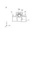
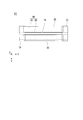
- FIG. 2 is a cross-sectional view of the heat exchanger shown in FIG. 1 in the direction of line A 1 -A 2 .
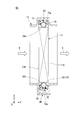
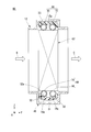
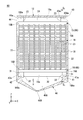
- FIG. 2 is a cross-sectional view of the heat exchanger shown in FIG. 1 in the B 1 -B 2 line direction.
- It is a front view which shows typically the heat exchanger which concerns on the 1st modification of the 1st Embodiment of this invention.
- It is a front view showing typically the heat exchanger concerning the 2nd modification of a 1st embodiment of the present invention.
- FIG. 1 is a cross-sectional view of the heat exchanger shown in FIG. 1 in the direction of line A 1 -A 2 .
- FIG. 2 is a cross-sectional view of the heat exchanger shown in FIG. 1 in the B 1 -B 2 line direction.
- It is a front view which shows typically the heat exchange
- FIG. 7 is a cross-sectional view of the heat exchanger shown in FIG. 6 in the D 1 -D 2 line direction. It is a front view which shows typically the heat exchanger which concerns on the 2nd Embodiment of this invention.
- FIG. 9 is a cross-sectional view of the heat exchanger shown in FIG. 8 in the E 1 -E 2 line direction. It is the figure which looked at the heat exchanger main body of the state which removed the case from the heat exchanger shown in FIG. It is a front view which shows typically the heat exchanger which concerns on the modification of the 2nd Embodiment of this invention.
- FIG. 12 is a cross-sectional view of the heat exchanger shown in FIG. 11 in the G 1 -G 2 line direction.
- FIG. 16 is a cross-sectional view of the heat exchanger shown in FIG. 15 in the I 1 -I 2 line direction.
- FIG. 16 is a cross-sectional view of the heat exchanger shown in FIG. 15 in the J 1 -J 2 line direction.
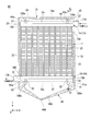
- FIGS. 1 to 3 A heat exchanger 10 according to a first embodiment of the present invention will be described with reference to FIGS. 1 to 3, the X direction is the width direction of the heat exchanger body 11, the Y direction is the depth direction of the heat exchanger body 11 orthogonal to the X direction, and the Z direction is a vertical direction orthogonal to the XY plane. (Vertical direction) is shown.
- FIG. 1 the case 12 is shown in cross section for convenience of explanation.
- B direction B direction
- C is the air conditioning air after heat exchange moves.
- Each direction (hereinafter referred to as “C direction”) is shown.
- positioned between the upper header 13 and the lower header 14 among the heat exchanger main bodies 11 is simplified and shown in figure.
- the heat exchanger 10 includes a heat exchanger main body 11 and a case 12.
- the heat exchanger body 11 includes an upper header 13, a lower header 14, a plurality of tubes 18, a plurality of fins 21, a pair of side plates 22, an upper cushioning material 23, an upper damping material 24, and a lower part It has a buffer material 31 and a lower vibration damping material 32.
- the upper header 13 constitutes the upper end portion of the heat exchanger body 11.
- the upper header 13 is composed of one upper tubular member 15.
- the upper tubular member 15 is arranged extending in the X direction.
- the upper tubular member 15 is connected to the upper ends of the plurality of tubes 18.
- the upper tubular member 15 has an outer peripheral surface 15a, one end 15A, an end 15Ae including one end 15A, the other end 15B, and an end 15Be including the other end 15B.
- the outer peripheral surface 15a is a surface on which the upper shock absorbing material 23 and the upper vibration damping material 24 are provided.
- One end 15A is an open end, and the other end 15B is a closed end.
- One end 15A is connected to the refrigerant introduction pipe 17A.
- the refrigerant flowing in the refrigerant introduction pipe 17A is supplied to one end 15A of the upper tubular member 15.
- the upper tubular member 15 distributes the refrigerant to the plurality of tubes 18.
- the end portions 15Ae and 15Be are portions where the upper cushioning material 23 is provided.
- the end portions 15Ae and 15Be are supported by the case 12 via the upper cushioning material 23.
- both ends of the upper tubular member 15 both ends of the upper header 13 may be described as “both ends 15Ae, 15Be”.
- the lower header 14 constitutes the lower end of the heat exchanger body 11.
- the lower header 14 is provided so as to be opposed to the upper header 13 in a state of being spaced below the upper header 13. That is, the upper header 13 and the lower header 14 are provided with an interval in the Z direction (up and down direction).
- the lower header 14 is composed of one lower tubular member 16.
- the lower tubular member 16 extends in the X direction.
- the lower tubular member 16 is connected to the lower ends of the plurality of tubes 18.
- the lower tubular member 16 has an outer peripheral surface 16a, one end 16A, an end 16Ae including one end 16A, the other end 16B, and an end 16Be including the other end 16B.
- the outer peripheral surface 16a is a surface on which the lower shock absorbing material 31 and the lower vibration damping material 32 are provided.
- One end 16A is a closed end, and the other end 16B is an open end.
- the other end 16B is connected to the refrigerant outlet pipe 17B.
- the other end 16B of the lower tubular member 16 passes through the plurality of tubes 18 and guides the refrigerant that has exchanged heat with the air-conditioning air to the refrigerant outlet pipe 17B.
- the end portions 16Ae and 16Be are portions where the lower cushioning material 31 is provided (portions corresponding to the lower cushioning material formation region).
- the end portions 16Ae and 16Be are supported by the case 12 via the lower cushioning material 31.
- both ends of the lower tubular member 16 both ends of the lower header 14 may be described as “both ends 16Ae, 16Be”.
- the material of the upper header 13 and the lower header 14 described above for example, aluminum or aluminum alloy can be used.
- the plurality of tubes 18 are provided between the upper header 13 and the lower header 14.
- the plurality of tubes 18 extend in the Z direction and are connected to the upper header 13 and the lower header 14.
- the plurality of tubes 18 are arranged in the X direction at a predetermined interval.
- a refrigerant flows through the plurality of tubes 18.
- the refrigerant flowing through the plurality of tubes 18 exchanges heat with air-conditioning air supplied to the front surface 11a of the heat exchanger body 11 from the B direction.
- the air-conditioning air after heat exchange passes through the back surface 11b of the heat exchanger body 11 and flows in the C direction.
- condensed water is generated on the surface of the heat exchanger body 11.
- the condensed water travels along the surface of the heat exchanger body 11 and moves to the lower end side of the heat exchanger body 11.
- the plurality of fins 21 are provided between the plurality of tubes 18 (between the tubes 18 provided at positions adjacent to each other).
- the pair of side plates 22 is provided so as to sandwich a structure including a plurality of tubes and a plurality of fins 21 from the X direction.
- the pair of side plates 22 has an upper end connected to the upper tubular member 15 (upper header 13) and a lower end connected to the lower tubular member 16 (lower header 14).
- the materials of the plurality of tubes 18, the plurality of fins 21, and the pair of side plates 22 described above for example, aluminum or aluminum alloy can be used.
- the upper cushioning material 23 is provided so as to cover the upper outer peripheral surface 15a of both end portions 15Ae and 15Be of the upper tubular member 15.
- a foam material can be used as the upper cushioning material 23.
- the upper cushioning material 23 includes heat insulation between the case 12 and the structure excluding the upper cushioning material 23 from the heat exchanger main body 11, and the structure and case 12 excluding the upper cushioning material 23 from the heat exchanger main body 11. It has the function of absorbing dimensional tolerances.
- the upper damping material 24 is provided so as to cover the upper outer peripheral surface 15a of the upper tubular member 15 located between the both end portions 15Ae and 15Be.
- the upper vibration damping material 24 is a vibration damping material having adhesiveness.
- the upper damping material 24 has an adhesive surface 24a that comes into contact with the outer peripheral surface 15a.
- the upper damping material 24 is provided so as not to overlap the upper shock absorbing material 23 (in other words, not to be disposed between the upper tubular member 15 and the upper shock absorbing material 23).
- the upper damping material 24 has a function of reducing noise generated from the heat exchanger body 11 by damping the vibration of the heat exchanger body 11.
- a material mainly composed of butyl rubber and containing an adhesive can be used as the upper damping material 24.
- the lower cushioning material 31 is provided so as to cover the lower outer peripheral surface 16a of both end portions 16Ae and 16Be of the lower tubular member 16. Part of the two lower cushioning materials 31 is exposed in a condensed water discharge space 46A described later.
- the lower cushioning material 31 includes heat insulation between the case 12 and the structure excluding the lower cushioning material 31 from the heat exchanger main body 11, and the structure and case 12 excluding the lower cushioning material 31 from the heat exchanger main body 11. It has the function of absorbing dimensional tolerances.
- a foam material can be used as the lower cushioning material 31.
- the lower damping material 32 covers the lower outer peripheral surface 16a of the lower tubular member 16 located between the both end portions 16Ae and 16Be.
- the lower damping material 32 is a damping material having adhesiveness.
- the lower vibration damping material 32 has an adhesive surface 32a that contacts the outer peripheral surface 16a.
- a part of both ends of the lower damping material 32 is provided to extend to a part of both ends 16Ae and 16Be of the lower tubular member 16. That is, a part of the lower damping material 32 is disposed on the outer peripheral surface 16a at the lower part of the both end portions 16Ae and 16Be.
- a portion of the lower damping member 32 that extends to a part of the outer peripheral surface 16a at the lower portion of the both end portions 16Ae and 16Be of the lower tubular member 16 is an end portion (end portion) 16Ae or the end 16Be) and the lower cushioning material 31.
- the lower damping material 32 for example, a material mainly containing butyl rubber and containing an adhesive can be used.
- the case 12 has a shape that can contact the upper and lower ends of the heat exchanger main body 11 and a pair of side surfaces arranged in the X direction.
- the case 12 accommodates the heat exchanger body 11.
- the end of the case 12 that faces the front surface 11a and the back surface 11b of the heat exchanger body 11 is an open end.
- the case 12 includes a first contact portion 41, a second contact portion 42, a third contact portion 43, a fourth contact portion 44, and a condensed water discharge portion 46.
- the first contact portion 41 has a shape capable of accommodating a part of the lower cushioning material 31 provided at the end portion 16Ae of the lower header 14.
- the first contact portion 41 includes a lower surface of the lower cushioning material 31 provided at the end portion 16Ae and a contact surface 41a with which a pair of side surfaces disposed in the Y direction are in contact.
- the first contact portion 41 regulates the position of one lower corner portion of the pair of lower corner portions of the heat exchanger body 11.
- the second contact portion 42 has a shape capable of accommodating a part of the lower cushioning material 31 provided at the end portion 16Be of the lower tubular member 16.
- the second contact portion 42 includes a lower surface of the lower cushioning material 31 provided at the end portion 16Be and a contact surface 42a with which a pair of side surfaces disposed in the Y direction are in contact.
- the second contact portion 42 regulates the position of one lower corner portion of the pair of lower corner portions of the heat exchanger main body 11.
- the first and second contact portions 41 and 42 described above support the lower end of the heat exchanger body 11.
- the third contact portion 43 has a shape capable of accommodating a part of the upper cushioning material 23 provided at the end portion 15Ae of the upper tubular member 15.
- the third contact portion 43 has an upper surface of the upper cushioning material 23 provided at the end portion 15Ae and a contact surface 43a with which a pair of side surfaces disposed in the Y direction are in contact.
- the third contact portion 43 restricts the position of one upper corner portion of the pair of upper corner portions of the heat exchanger body 11.
- the fourth contact portion 44 has a shape capable of accommodating a part of the upper cushioning material 23 provided at the end portion 15Be of the upper tubular member 15.
- the fourth contact portion 44 has an upper surface of the upper cushioning material 23 provided at the end portion 15Be and a contact surface 44a with which a pair of side surfaces disposed in the Y direction are in contact.
- the fourth contact portion 44 regulates the position of the other upper corner portion of the pair of upper corner portions of the heat exchanger body 11.
- the condensed water discharge part 46 is provided below the first and second contact parts 41 and 42.
- the condensed water discharge part 46 has a condensed water discharge space 46A and a discharge port 46B.
- the condensed water discharge space 46 ⁇ / b> A exposes a part of the two lower shock absorbers 31 and the lower vibration damping member 32 disposed between the two lower shock absorbers 31.
- the condensed water discharge space 46 ⁇ / b> A has a shape in which the width becomes narrower from the heat exchanger body 11 toward the lower side of the heat exchanger body 11. The condensed water that has moved to the lower damping material 32 is dropped into the condensed water discharge space 46A.
- the discharge port 46 ⁇ / b> B is provided at the lower end of the condensed water discharge unit 46.
- the discharge port 46 ⁇ / b> B is an opening for leading condensed water to the outside of the heat exchanger 10.
- a part of both ends of the lower damping material 32 extends between the lower header 14 (lower tubular member 16) and the lower cushioning material 31. Accordingly, it is possible to support a part of both end portions of the lower damping material 32 using the lower cushioning material 31 supported by the first and second contact portions 41 and 42. Thereby, even when the adhesive force of the lower damping material 32 is reduced due to, for example, condensed water flowing along the surface of the heat exchanger body 11 to the lower end side of the heat exchanger body 11 or a change over time of the lower damping material 32. It can suppress that the lower damping material 32 peels off from the heat exchanger main body 11.
- the heat exchanger 50 is configured in the same manner as the heat exchanger 10 of the first embodiment except that the lower damping material 32 is provided on the entire outer peripheral surface 16a of the lower portion of the end portions 16Ae and 16Be of the lower tubular member 16. Has been.
- the heat exchanger 50 according to the first modification of the first embodiment having such a configuration can obtain the same effects as the heat exchanger 10 of the first embodiment described above.
- the heat exchanger 55 is the first except that the lower cushioning material 31 is provided so as to cover the lower damping material 32 provided between the first contact portion 41 and the second contact portion 42. It is comprised similarly to the heat exchanger 10 of 1 embodiment.
- the lower shock absorber 32 is provided by the lower shock absorber 31 by providing the lower shock absorber 31 so as to cover the entire lower vibration damper 32. Can be supported. Thereby, even when the adhesive force of the lower damping material 32 falls, it can further suppress that the lower damping material 32 peels off from the heat exchanger main body 11.
- the heat exchanger 60 is the heat exchanger according to the first embodiment except that a part of both ends of the upper damping material 24 is arranged to extend between the upper header 13 and the upper cushioning material 23. 10 is the same.
- part of both end portions of the upper damping material 24 is interposed between the upper header 13 (upper tubular member 15) and the upper cushioning material 23.
- the upper cushioning material 23 supported by the third and fourth abutting portions 43 and 44 the positions of a part of both end portions of the upper damping material 24 are regulated by extending and arranging. Is possible. Thereby, even when the adhesive force of the upper damping material 24 falls, it can suppress that the upper damping material 24 peels off from the heat exchanger main body 11.
- heat exchanger 60 according to the third modification of the first embodiment can obtain the same effects as the heat exchanger 10 of the first embodiment described above.
- U-shaped concave portions are provided on the upper and lower sides of the case 12, respectively, the upper end portion of the heat exchanger body 11 is accommodated in one concave portion, and the heat exchanger main body is accommodated in the other concave portion.
- the case 12 does not necessarily have the above-described recess.
- the shape of the case 12 is, for example, one of the pair of surfaces disposed in the Y direction of the upper cushioning material 23 and the pair of surfaces disposed in the Y direction of the lower cushioning material 31. Among these, it is good also as a shape which one surface, the upper end surface of the upper shock absorbing material 23, and the lower end surface of the lower shock absorbing material 31 can contact. Or the shape of case 12 is good also as a shape which the upper end surface of the upper shock absorbing material 23 and the lower end surface of the lower shock absorbing material 31 can contact, for example.
- the heat exchanger 65 has a heat exchanger body 67 having an upper header 66 and a lower header 68 instead of the upper header 13 and the lower header 14 constituting the heat exchanger body 11 described in the first embodiment. Other than that, the configuration is the same as that of the heat exchanger 10.
- the upper header 66 is configured in the same manner as the upper header 13 except that the upper header 66 includes two upper tubular members 15 described in the first embodiment (including a pair of upper tubular members 15).
- the pair of upper tubular members 15 are arranged in the Y direction with a gap interposed therebetween.
- the pair of upper tubular members 15 extends in the X direction (the same direction).
- An upper cushioning material 23 is provided at the end portions 15 ⁇ / b> Ae and 15 ⁇ / b> Be of each upper tubular member 15.
- an upper damping material 24 is provided between the end 15Ae and the end 15Be.
- the lower header 68 is configured in the same manner as the lower header 14 except that the lower header 68 includes two lower tubular members 16 described in the first embodiment (including a pair of lower tubular members 16).
- the pair of lower tubular members 16 are arranged in the Y direction with a gap interposed.
- the pair of upper tubular members 16 extends in the X direction (the same direction).
- Part of both end portions of the lower vibration damping material 32 extends to the end portions 16 ⁇ / b> Ae and 16 ⁇ / b> Be of each lower tubular member 16.
- the lower damping material 32 is provided in each lower tubular member 16 in a state where a gap 71 between which the condensed water can move to the condensed water discharge space 46 ⁇ / b> A is possible between the two lower tubular members 16.
- a lower cushioning material 31 is provided at the end portions 16Ae and 16Be of the pair of lower tubular members 16 so as to surround a part of both ends of the lower damping material 32 together.
- the lower cushioning material 31 is disposed so as to surround the lower damping material 32 provided at both ends 16Ae and 16Be of the pair of lower tubular members 16, thereby providing the pair of lower tubular members.
- the amount of use of the lower cushioning material 31 can be reduced as compared with the case where the lower cushioning material 31 is arranged so as to surround the lower damping material. Thereby, the cost of the heat exchanger main body 67 can be reduced.
- the heat exchanger 65 of the second embodiment configured as described above can obtain the same effects as the heat exchanger 10 of the first embodiment described above.
- the heat exchanger 75 which concerns on the modification of 2nd Embodiment is demonstrated.
- the heat exchanger 75 according to the modified example of the second embodiment is the same as that of the first embodiment except that a part of both end portions of the upper damping material 24 and the upper cushioning material 23 are arranged to overlap each other.
- the heat exchanger 60 is configured in the same manner as the third modification.
- the heat exchanger 75 according to the modified example of the second embodiment having such a configuration can obtain the same effects as the heat exchanger 60 of the third modified example of the first embodiment.
- the lower cushioning material 31 may be arranged so as to collectively surround the lower damping material 32 provided on the pair of lower tubular members 16. .
- the heat exchanger 80 is configured in the same manner as the heat exchanger 65 of the second embodiment except that a heat exchanger main body 81 is provided instead of the heat exchanger main body 67.
- the heat exchanger main body 81 is provided with a lower cushioning material 31 so as to collectively surround the lower damping material 32 provided on the pair of lower tubular members 16, and on the lower cushioning material 31 positioned between the lower tubular members 16.
- the configuration is the same as that of the heat exchanger body 67 except that a plurality of through portions 31A are provided.
- the plurality of through portions 31A function as a path for guiding the condensed water generated in the heat exchanger body 11 to the condensed water discharge space 46A.
- the lower cushioning material 31 is disposed so as to collectively surround the lower damping material 32 provided on the pair of lower tubular members 16, thereby providing a pair of lower portions. It becomes possible to support the lower damping material 32 provided between the both end portions 16Ae and 16Be of the tubular member 16. Thereby, it can further suppress that the lower damping material 32 peels off from the heat exchanger main body 81 (a pair of lower tubular member 16).
- the amount of the lower cushioning material 31 can be reduced as compared with the case where the lower cushioning material 31 is disposed so as to surround the lower damping material 32 provided on the pair of lower tubular members 16. Thereby, the cost of the heat exchanger main body 81 can be reduced. Furthermore, by providing a plurality of through portions 31A in the lower cushioning material 31 disposed between the pair of lower tubular members 16, the condensed water generated in the heat exchanger body 81 can be guided to the condensed water discharge portion 46. It becomes possible. Thereby, it can suppress that condensed water accumulates in the lower end of the heat exchanger main body 81. FIG.
- FIG. 14 as an example, a case where slit-like through grooves are provided as the plurality of through portions 31 ⁇ / b> A has been described as an example, but the plurality of through portions 31 ⁇ / b> A is not limited thereto.
- a plurality of penetration parts 31A you may use a plurality of penetration holes, for example.
- the number of penetration parts 31A does not need to be plural, and may be one.
- FIGS. 15 to 17 A heat exchanger 90 according to a fourth embodiment will be described with reference to FIGS. 15 to 17. 15 to 17, the same components as those shown in FIGS. 8 to 10 are denoted by the same reference numerals.
- the heat exchanger 90 is configured in the same manner as the heat exchanger 65 of the second embodiment except that it has a heat exchanger body 93 instead of the heat exchanger body 67.
- the heat exchanger main body 93 includes first and second lower vibration damping materials 91 and 92 instead of the lower vibration damping material 32, and is provided at both ends of the lower shock absorber 31 and the first lower vibration damping material 91.
- the heat exchanger body 67 is configured in the same manner as the heat exchanger body 67 except that a part thereof is overlapped.
- the first lower damping material 91 is adhered to the outer peripheral surface 16 a of one lower tubular member 16.
- the first lower vibration damping material 91 has an adhesive surface 91 a that contacts the outer peripheral surface 16 a of one lower tubular member 16.
- the second lower damping material 92 is adhered to the outer peripheral surface 16 a of the other lower tubular member 16.
- the second lower vibration damping material 92 has an adhesive surface 92 a that contacts the outer peripheral surface 16 a of the other lower tubular member 16.
- the area of the adhesive surface 92 a of the second lower vibration damping material 92 is larger than the area of the adhesive surface 91 a of the first lower vibration damping material 91.
- the area of the adhesive surface 92 a of the second lower vibration damping material 92 is an area where a sufficient adhesive force can be obtained with respect to the other lower tubular member 16.
- the area of the adhesion surface 91a of the first lower vibration damping material 91 is smaller than the area of the adhesion surface 92a of the second lower vibration damping material 92, and one lower part
- the first lower vibration damping material 31 and the both ends of the first lower vibration damping material 91 are overlapped to overlap the first lower vibration damping material 91. Peeling of the material 91 can be suppressed.
- the adhesive force of the second lower damping material 92 to the other lower tubular member 16 is sufficiently strong, the lower cushioning material 31 and the both ends of the second lower damping material 92 need not be overlapped. Good.
- the 1st upper damping material provided in one upper tubular member 15, and the 2nd upper damping material provided in the other upper tubular member 15, and is the 1st upper damping material
- the area of the adhesive surface of the first upper damping material is smaller than the area of the adhesive surface of the second upper vibration damping material and the first upper damping material is weak against one upper tubular member, By peeling only the both ends of the upper vibration damping material, peeling of the first upper vibration damping material may be suppressed.
- the case where the heat exchanger bodies 11, 67, 81, 93 are arranged so as to extend in the vertical direction (Z direction) is described as an example.
- the heat exchanger bodies 11, 67, 81, 93 may be arranged so as to intersect with the vertical direction and the upper headers 13, 66 are located above the lower headers 14, 68.
- the upper damping material 24, the lower damping material 32, the first lower damping material 91, and the second lower damping material 92 have adhesiveness.
- the case has been described as an example, for example, a configuration in which an upper damping material and a lower damping material that do not have adhesiveness are adhered or bonded to the upper header and the lower header using an adhesive or an adhesive. Applicable.
- the present invention is applicable to a heat exchanger.
Landscapes
- Engineering & Computer Science (AREA)
- Physics & Mathematics (AREA)
- Thermal Sciences (AREA)
- Mechanical Engineering (AREA)
- General Engineering & Computer Science (AREA)
- Heat-Exchange Devices With Radiators And Conduit Assemblies (AREA)
- Air-Conditioning For Vehicles (AREA)
Abstract
少なくとも下部ヘッダ(14)を構成する下部管状部材(16)の両端部(16Ae,16Be)のうち、両端部(16Ae,16Be)に設けられた下部緩衝材(31)から露出された下部管状部材(16)の下部の外周面(16a)に設けられ、少なくとも両端部の一部が下部管状部材(16)と下部緩衝材(31)との間に延在し、粘着性を有する下部制振材(32)を含む熱交換器本体(11)と、下部緩衝材(31)が当接される第1及び第2の当接部(41,42)、及び凝縮水を外部に排出する凝縮水排出部(46)を含むケース(12)と、を有する。
Description
本発明は、熱交換器に関する。
本願は、2016年11月18日に、日本に出願された特願2016-225161号に基づき優先権を主張し、その内容をここに援用する。
本願は、2016年11月18日に、日本に出願された特願2016-225161号に基づき優先権を主張し、その内容をここに援用する。
車両用空調装置は、ケースと、ケース内に収容され、冷媒が流れる複数のチューブ及びチューブ間に配置されたフィンを含む熱交換器本体と、を備えた熱交換器を有する。
上記熱交換器では、ケース内に導入された空調用空気と熱交換器本体のチューブ内を流れる冷媒とを熱交換させることで、空調用空気を冷却する。
このとき、熱交換器本体の表面には、凝縮水が発生する。凝縮水は、熱交換器本体の表面を伝って、熱交換器本体の下端側へ流れる。
上記熱交換器では、ケース内に導入された空調用空気と熱交換器本体のチューブ内を流れる冷媒とを熱交換させることで、空調用空気を冷却する。
このとき、熱交換器本体の表面には、凝縮水が発生する。凝縮水は、熱交換器本体の表面を伝って、熱交換器本体の下端側へ流れる。
上記構成とされた熱交換器では、熱交換器本体を金属材料で構成すると、チューブ内を冷媒が流れることで熱交換器本体が振動し、騒音が発生する可能性があった。
特許文献1には、熱交換器本体から発生する騒音を抑制する目的で、熱交換器本体に制振材を設けることが開示されている。
特許文献1には、熱交換器本体から発生する騒音を抑制する目的で、熱交換器本体に制振材を設けることが開示されている。
ところで、上記制振材としては、粘着性を有する制振材を用いる場合がある。このような制振材を用いる場合、上述した凝縮水や経時変化により、制振材と熱交換器本体との間の粘着力が低下して、熱交換器本体から制振材が剥がれ落ちる可能性があった。
そこで、本発明は、熱交換器本体から制振材が剥がれ落ちることを抑制可能な熱交換器を提供することを目的とする。
上記課題を解決するため、本発明の一態様に係る熱交換器は、上下方向に間隔を空けて設けられ、管状とされた上部ヘッダ及び下部ヘッダ、前記上部ヘッダと前記下部ヘッダとの間に配列され、前記上部ヘッダ及び前記下部ヘッダと接続されるとともに冷媒が流れる複数のチューブ、互いに隣り合う位置に設けられた前記チューブの間に設けられたフィン、前記下部ヘッダの両端部の下部の外周面を覆うように設けられた下部緩衝材、及び前記下部ヘッダの両端部に設けられた前記下部緩衝材から露出された前記下部ヘッダの下部の外周面に設けられ、少なくとも両端部の一部が前記下部ヘッダと前記下部緩衝材との間に延在し、かつ粘着性を有する下部制振材を含む熱交換器本体と、前記下部ヘッダの両端部に設けられた前記下部緩衝材のうち、一方が当接される第1の当接部、及び他方が当接される第2の当接部、並びに前記第1及び第2の当接部よりも下方に設けられ、前記熱交換器本体に付着した凝縮水を外部に排出する凝縮水排出部を含むケースと、を備える。
本発明によれば、少なくとも下部制振材の両端部の一部を下部ヘッダと下部緩衝材との間に延在して配置させることにより、第1及び第2の当接部により支持された下部緩衝材を用いて、下部制振材の両端部の一部を支持することが可能となる。
これにより、熱交換器本体の表面に沿って熱交換器本体の下端側に流れる凝縮水や下部制振材の経時変化等により、下部制振材の粘着力が低下した場合でも熱交換器本体(下部ヘッダ)から下部制振材が剥がれ落ちることを抑制できる。
これにより、熱交換器本体の表面に沿って熱交換器本体の下端側に流れる凝縮水や下部制振材の経時変化等により、下部制振材の粘着力が低下した場合でも熱交換器本体(下部ヘッダ)から下部制振材が剥がれ落ちることを抑制できる。
また、上記本発明の一態様に係る熱交換器において、前記下部ヘッダは、互いに隣り合うように配置され、かつ同一方向に延在する一対の下部管状部材を含み、少なくとも前記一対の下部管状部材の両端部の一部には、それぞれ前記下部制振材が設けられており、前記下部緩衝材は、前記一対の下部管状部材の両端部に設けられた前記下部制振材をまとめて囲むように配置されていてもよい。
このように、一対の下部管状部材の両端部に設けられた下部制振材をまとめて囲むように下部緩衝材を配置させることで、一対の下部管状部材に設けられた下部制振材をそれぞれ囲むように下部緩衝材を配置させた場合よりも下部緩衝材の使用を少なくすることが可能となる。これにより、熱交換器本体のコストを低減することができる。
また、上記本発明の一態様に係る熱交換器において、前記下部ヘッダは、互いに隣り合うように配置され、かつ同一方向に延在する一対の下部管状部材を含み、少なくとも前記一対の下部管状部材の両端部の一部には、それぞれ前記下部制振材が設けられており、前記下部緩衝材は、前記一対の下部管状部材に設けられた前記下部制振材の全体をまとめて囲むように配置されており、前記一対の下部管状部材の間に配置された前記下部緩衝材に貫通部を有してもよい。
このように、一対の下部管状部材に設けられた下部制振材の全体をまとめて囲むように下部緩衝材を配置させることで、一対の下部管状部材の両端部の間に設けられた下部制振材を支持することが可能となる。これにより、熱交換器本体(下部ヘッダ)から下部制振材が剥がれ落ちることをさらに抑制できる。
また、一対の下部管状部材に設けられた下部制振材のそれぞれ囲むように下部緩衝材を配置させた場合よりも下部緩衝材の量を少なくすることが可能となる。これにより、熱交換器本体のコストを低減することができる。
さらに、一対の下部管状部材の間に配置された下部緩衝材に貫通部を設けることで、凝縮水を凝縮水排出部に案内することが可能となる。これにより、熱交換器本体の下端に凝縮水が溜まることを抑制できる。
さらに、一対の下部管状部材の間に配置された下部緩衝材に貫通部を設けることで、凝縮水を凝縮水排出部に案内することが可能となる。これにより、熱交換器本体の下端に凝縮水が溜まることを抑制できる。
また、上記本発明の一態様に係る熱交換器において、前記下部ヘッダは、互いに隣り合うように配置され、かつ同一方向に延在する一対の下部管状部材を含み、前記下部制振材は、前記一対の下部管状部材のうち、一方の下部管状部材に設けられ、粘着性を有する第1の下部制振材と、他方の下部管状部材に設けられ、粘着性を有する第2の下部制振材と、を含み、前記一方の下部管状部材と接触する前記第1の下部制振材の粘着面の面積が、前記他方の下部管状部材と接触する前記第2の下部制振材の粘着面の面積よりも小さい場合、前記下部緩衝材と前記第1の下部制振材の両端部のみとを重ねてもよい。
このように、第1の下部制振材の粘着面の面積が第2の下部制振材の粘着面の面積よりも小さく、一方の下部管状部材に対する第1の下部制振材の粘着力が弱い場合には、下部緩衝材と第1の下部制振材の両端部のみとを重ねることで、第1の下部制振材の剥がれを抑制することができる。
他方の下部管状部材に対する第2の下部制振材の粘着力が十分に強い場合には、下部緩衝材と第2の下部制振材の両端部とを重ねなくてもよい。
他方の下部管状部材に対する第2の下部制振材の粘着力が十分に強い場合には、下部緩衝材と第2の下部制振材の両端部とを重ねなくてもよい。
また、上記本発明の一態様に係る熱交換器において、前記熱交換器本体は、前記上部ヘッダの両端部の上部の外周面を覆うように設けられた上部緩衝材と、前記上部ヘッダの両端部に設けられた前記上部緩衝材から露出された前記上部ヘッダの上部の外周面に設けられ、少なくとも両端部の一部が前記上部ヘッダと前記上部緩衝材との間に延在し、粘着性を有する上部制振材と、を含み、前記ケースは、前記上部ヘッダの両端部に設けられた前記上部緩衝材のうち、一方が当接される第3の当接部、及び他方が当接される第4の当接部を含んでもよい。
このように、少なくとも上部制振材の両端部の一部を上部ヘッダと上部緩衝材との間に延在して配置させることにより、第3及び第4の当接部により支持された上部緩衝材を用いて、上部制振材の両端部の一部を支持することが可能となる。
これにより、熱交換器本体の表面に発生する凝縮水や上部制振材の経時変化により、上部制振材の粘着力が低下した場合でも熱交換器本体(上部ヘッダ)から上部制振材が剥がれ落ちることを抑制できる。
これにより、熱交換器本体の表面に発生する凝縮水や上部制振材の経時変化により、上部制振材の粘着力が低下した場合でも熱交換器本体(上部ヘッダ)から上部制振材が剥がれ落ちることを抑制できる。
また、上記本発明の一態様に係る熱交換器において、前記上部ヘッダは、互いに隣り合うように配置され、かつ同一方向に延在する一対の上部管状部材を含み、少なくとも前記一対の上部管状部材の両端部の一部には、それぞれ前記上部制振材が設けられており、前記上部緩衝材は、前記一対の上部管状部材の両端部に設けられた前記上部制振材をまとめて囲むように配置されていてもよい。
このように、一対の上部管状部材の両端部に設けられた上部制振材をまとめて囲むように上部緩衝材を配置させることで、一対の上部管状部材に設けられた上部制振材をそれぞれ囲むように上部緩衝材を配置させた場合よりも上部緩衝材の使用量を少なくすることが可能となるので、熱交換器本体のコストを低減できる。
また、上記本発明の一態様に係る熱交換器において、前記上部ヘッダは、互いに隣り合うように配置され、かつ同一方向に延在する一対の上部管状部材を含み、少なくとも前記一対の上部管状部材の両端部の一部には、それぞれ前記上部制振材が設けられており、前記上部緩衝材は、前記一対の上部管状部材に設けられた前記上部制振材の全体をまとめて囲むように配置されていてもよい。
このように、一対の上部管状部材に設けられた上部制振材の全体をまとめて囲むように上部緩衝材を設けることで、一対の上部管状部材の両端部の間に設けられた上部制振材を支持することが可能となる。これにより、熱交換器本体から上部制振材が剥がれ落ちることをさらに抑制することができる。
本発明によれば、熱交換器本体から制振材が剥がれ落ちることを抑制することができる。
以下、図面を参照して本発明を適用した実施形態について詳細に説明する。
(第1の実施形態)
図1~図3を参照して、本発明の第1の実施形態の熱交換器10について説明する。図1~図3では、X方向は熱交換器本体11の幅方向、Y方向はX方向に対して直交する熱交換器本体11の奥行方向、Z方向はXY平面に対して直交する鉛直方向(上下方向)をそれぞれ示している。
図1では、説明の便宜上、ケース12を断面で図示する。図2において、Bは熱交換器本体11の正面11a側に供給される外気(空調用空気)の移動方向(以下、「B方向」という)、Cは熱交換後の空調用空気が移動する方向(以下、「C方向」という)をそれぞれ示している。
また、図2及び図3では、熱交換器本体11のうち、上部ヘッダ13と下部ヘッダ14との間に配置される部分を簡略化して図示する。
図1~図3を参照して、本発明の第1の実施形態の熱交換器10について説明する。図1~図3では、X方向は熱交換器本体11の幅方向、Y方向はX方向に対して直交する熱交換器本体11の奥行方向、Z方向はXY平面に対して直交する鉛直方向(上下方向)をそれぞれ示している。
図1では、説明の便宜上、ケース12を断面で図示する。図2において、Bは熱交換器本体11の正面11a側に供給される外気(空調用空気)の移動方向(以下、「B方向」という)、Cは熱交換後の空調用空気が移動する方向(以下、「C方向」という)をそれぞれ示している。
また、図2及び図3では、熱交換器本体11のうち、上部ヘッダ13と下部ヘッダ14との間に配置される部分を簡略化して図示する。
熱交換器10は、熱交換器本体11と、ケース12と、を有する。熱交換器本体11は、上部ヘッダ13と、下部ヘッダ14と、複数のチューブ18と、複数のフィン21と、一対のサイドプレート22と、上部緩衝材23と、上部制振材24と、下部緩衝材31と、下部制振材32と、を有する。
上部ヘッダ13は、熱交換器本体11の上端部を構成している。上部ヘッダ13は、1つの上部管状部材15で構成されている。上部管状部材15は、X方向に延在して配置されている。上部管状部材15は、複数のチューブ18の上端と接続されている。
上部管状部材15は、外周面15aと、一方の端15Aと、一方の端15Aを含む端部15Aeと、他方の端15Bと、他方の端15Bを含む端部15Beと、を有する。
上部管状部材15は、外周面15aと、一方の端15Aと、一方の端15Aを含む端部15Aeと、他方の端15Bと、他方の端15Bを含む端部15Beと、を有する。
外周面15aは、上部緩衝材23、及び上部制振材24が設けられる面である。
一方の端15Aは、開放端とされており、他方の端15Bは、閉塞端とされている。一方の端15Aは、冷媒導入管17Aと接続されている。上部管状部材15の一方の端15Aには、冷媒導入管17A内を流れる冷媒が供給される。上部管状部材15は、複数のチューブ18に冷媒を分配する。
一方の端15Aは、開放端とされており、他方の端15Bは、閉塞端とされている。一方の端15Aは、冷媒導入管17Aと接続されている。上部管状部材15の一方の端15Aには、冷媒導入管17A内を流れる冷媒が供給される。上部管状部材15は、複数のチューブ18に冷媒を分配する。
端部15Ae,15Beは、上部緩衝材23が設けられる部分である。端部15Ae,15Beは、上部緩衝材23を介して、ケース12に支持されている。
なお、以下の説明において、上部管状部材15の両端部(上部ヘッダ13の両端部)を「両端部15Ae,15Be」と記載する場合がある。
なお、以下の説明において、上部管状部材15の両端部(上部ヘッダ13の両端部)を「両端部15Ae,15Be」と記載する場合がある。
下部ヘッダ14は、熱交換器本体11の下端部を構成している。下部ヘッダ14は、上部ヘッダ13から上部ヘッダ13の下方に離間した状態で対向するように設けられている。つまり、上部ヘッダ13及び下部ヘッダ14は、Z方向(上下方向)に間隔を空けて設けられている。
下部ヘッダ14は、1つの下部管状部材16で構成されている。下部管状部材16は、X方向に延在している。下部管状部材16は、複数のチューブ18の下端と接続されている。
下部管状部材16は、外周面16aと、一方の端16Aと、一方の端16Aを含む端部16Aeと、他方の端16Bと、他方の端16Bを含む端部16Beと、を有する。
下部管状部材16は、外周面16aと、一方の端16Aと、一方の端16Aを含む端部16Aeと、他方の端16Bと、他方の端16Bを含む端部16Beと、を有する。
外周面16aは、下部緩衝材31、及び下部制振材32が設けられる面である。
一方の端16Aは、閉塞端とされており、他方の端16Bは、開放端とされている。他方の端16Bは、冷媒導出管17Bと接続されている。下部管状部材16の他方の端16Bは、複数のチューブ18内を通過し、空調用空気と熱交換した冷媒を冷媒導出管17Bに導出する。
一方の端16Aは、閉塞端とされており、他方の端16Bは、開放端とされている。他方の端16Bは、冷媒導出管17Bと接続されている。下部管状部材16の他方の端16Bは、複数のチューブ18内を通過し、空調用空気と熱交換した冷媒を冷媒導出管17Bに導出する。
端部16Ae,16Beは、下部緩衝材31が設けられる部分(下部緩衝材形成領域に対応する部分)である。端部16Ae,16Beは、下部緩衝材31を介して、ケース12に支持されている。
なお、以下の説明において、下部管状部材16の両端部(下部ヘッダ14の両端部)を「両端部16Ae,16Be」と記載する場合がある。
なお、以下の説明において、下部管状部材16の両端部(下部ヘッダ14の両端部)を「両端部16Ae,16Be」と記載する場合がある。
上述した上部ヘッダ13及び下部ヘッダ14の材料としては、例えば、アルミニウムやアルミニウム合金等を用いることが可能である。
複数のチューブ18は、上部ヘッダ13と下部ヘッダ14との間に設けられている。複数のチューブ18は、Z方向に延在しており、上部ヘッダ13及び下部ヘッダ14と接続されている。複数のチューブ18は、所定の間隔を空けた状態で、X方向に配列されている。
複数のチューブ18内には、冷媒が流れている。複数のチューブ18内を流れる冷媒は、B方向から熱交換器本体11の正面11aに供給される空調用空気と熱交換する。熱交換後の空調用空気は、熱交換器本体11の背面11bを通過し、C方向に流れる。
上記熱交換時には、熱交換器本体11の表面に凝縮水が発生する。凝縮水は、熱交換器本体11の表面を伝って、熱交換器本体11の下端側に移動する。
上記熱交換時には、熱交換器本体11の表面に凝縮水が発生する。凝縮水は、熱交換器本体11の表面を伝って、熱交換器本体11の下端側に移動する。
複数のフィン21は、複数のチューブ18間(互いに隣り合う位置に設けられたチューブ18間)に設けられている。
一対のサイドプレート22は、複数のチューブ、及び複数のフィン21よりなる構造体をX方向から挟み込むように設けられている。一対のサイドプレート22は、上端が上部管状部材15(上部ヘッダ13)と接続されており、下端が下部管状部材16(下部ヘッダ14)と接続されている。
一対のサイドプレート22は、複数のチューブ、及び複数のフィン21よりなる構造体をX方向から挟み込むように設けられている。一対のサイドプレート22は、上端が上部管状部材15(上部ヘッダ13)と接続されており、下端が下部管状部材16(下部ヘッダ14)と接続されている。
上述した複数のチューブ18、複数のフィン21、及び一対のサイドプレート22の材料としては、例えば、アルミニウムやアルミニウム合金等を用いることが可能である。
上部緩衝材23は、上部管状部材15の両端部15Ae,15Beのうち、上部の外周面15aを覆うように設けられている。上部緩衝材23としては、例えば、発泡材を用いることが可能である。
上部緩衝材23は、熱交換器本体11から上部緩衝材23を除いた構造体とケース12との間の断熱、並びに熱交換器本体11から上部緩衝材23を除いた構造体とケース12との寸法公差を吸収する機能を有する。
上部緩衝材23は、熱交換器本体11から上部緩衝材23を除いた構造体とケース12との間の断熱、並びに熱交換器本体11から上部緩衝材23を除いた構造体とケース12との寸法公差を吸収する機能を有する。
上部制振材24は、両端部15Ae,15Beの間に位置する上部管状部材15のうち、上部の外周面15aを覆うように設けられている。上部制振材24は、粘着性を有する制振材である。上部制振材24は、外周面15aと接触する粘着面24aを有する。
上部制振材24は、上部緩衝材23と重ならないように(言い換えれば、上部管状部材15と上部緩衝材23との間に配置されないように)設けられている。
上部制振材24は、熱交換器本体11の振動を制振することで、熱交換器本体11から発生する騒音を低減させる機能を有する。
上部制振材24としては、例えば、ブチルゴムを主成分とし、粘着剤を含有したものを用いることが可能である。
上部制振材24は、上部緩衝材23と重ならないように(言い換えれば、上部管状部材15と上部緩衝材23との間に配置されないように)設けられている。
上部制振材24は、熱交換器本体11の振動を制振することで、熱交換器本体11から発生する騒音を低減させる機能を有する。
上部制振材24としては、例えば、ブチルゴムを主成分とし、粘着剤を含有したものを用いることが可能である。
下部緩衝材31は、下部管状部材16の両端部16Ae,16Beのうち、下部の外周面16aを覆うように設けられている。2つの下部緩衝材31の一部は、後述する凝縮水排出用空間46Aに露出されている。
下部緩衝材31は、熱交換器本体11から下部緩衝材31を除いた構造体とケース12との間の断熱、並びに熱交換器本体11から下部緩衝材31を除いた構造体とケース12との寸法公差を吸収する機能を有する。
下部緩衝材31としては、例えば、発泡材を用いることが可能である。
下部緩衝材31は、熱交換器本体11から下部緩衝材31を除いた構造体とケース12との間の断熱、並びに熱交換器本体11から下部緩衝材31を除いた構造体とケース12との寸法公差を吸収する機能を有する。
下部緩衝材31としては、例えば、発泡材を用いることが可能である。
下部制振材32は、両端部16Ae,16Beの間に位置する下部管状部材16のうち、下部の外周面16aを覆っている。下部制振材32は、粘着性を有する制振材である。
下部制振材32は、外周面16aと接触する粘着面32aを有する。
下部制振材32の両端部の一部は、下部管状部材16の両端部16Ae,16Beの一部に延出して設けられている。つまり、下部制振材32は、その一部が両端部16Ae,16Beの下部の外周面16aに配置されている。
下部制振材32は、外周面16aと接触する粘着面32aを有する。
下部制振材32の両端部の一部は、下部管状部材16の両端部16Ae,16Beの一部に延出して設けられている。つまり、下部制振材32は、その一部が両端部16Ae,16Beの下部の外周面16aに配置されている。
これにより、下部制振材32のうち、下部管状部材16の両端部16Ae,16Beの下部の外周面16aの一部に延出して設けられた部分は、下部管状部材16の端部(端部16Aeまたは端部16Be)と下部緩衝材31との間に配置されている。
下部制振材32としては、例えば、ブチルゴムを主成分とし、粘着剤を含有したものを用いることが可能である。
下部制振材32としては、例えば、ブチルゴムを主成分とし、粘着剤を含有したものを用いることが可能である。
ケース12は、熱交換器本体11の上端、下端、及びX方向に配置された一対の側面と接触可能な形状とされている。ケース12は、熱交換器本体11を収容している。ケース12は、熱交換器本体11の正面11a及び背面11bと対向する端が開放端とされている。
ケース12は、第1の当接部41と、第2の当接部42と、第3の当接部43と、第4の当接部44と、凝縮水排出部46と、を有する。
第1の当接部41は、下部ヘッダ14の端部16Aeに設けられた下部緩衝材31の一部を収容可能な形状とされている。第1の当接部41は、端部16Aeに設けられた下部緩衝材31の下面、及びY方向に配置された一対の側面が当接される当接面41aを有する。第1の当接部41は、熱交換器本体11の一対の下角部のうち、一方の下角部の位置を規制している。
第2の当接部42は、下部管状部材16の端部16Beに設けられた下部緩衝材31の一部を収容可能な形状とされている。
第2の当接部42は、端部16Beに設けられた下部緩衝材31の下面、及びY方向に配置された一対の側面が当接される当接面42aを有する。第2の当接部42は、熱交換器本体11の一対の下角部のうち、一方の下角部の位置を規制している。
上述した第1及び第2の当接部41,42は、熱交換器本体11の下端を支持している。
第2の当接部42は、端部16Beに設けられた下部緩衝材31の下面、及びY方向に配置された一対の側面が当接される当接面42aを有する。第2の当接部42は、熱交換器本体11の一対の下角部のうち、一方の下角部の位置を規制している。
上述した第1及び第2の当接部41,42は、熱交換器本体11の下端を支持している。
第3の当接部43は、上部管状部材15の端部15Aeに設けられた上部緩衝材23の一部を収容可能な形状とされている。第3の当接部43は、端部15Aeに設けられた上部緩衝材23の上面、及びY方向に配置された一対の側面が当接される当接面43aを有する。第3の当接部43は、熱交換器本体11の一対の上角部のうち、一方の上角部の位置を規制している。
第4の当接部44は、上部管状部材15の端部15Beに設けられた上部緩衝材23の一部を収容可能な形状とされている。第4の当接部44は、端部15Beに設けられた上部緩衝材23の上面、及びY方向に配置された一対の側面が当接される当接面44aを有する。第4の当接部44は、熱交換器本体11の一対の上角部のうち、他方の上角部の位置を規制している。
凝縮水排出部46は、第1及び第2の当接部41,42の下方に設けられている。凝縮水排出部46は、凝縮水排出用空間46Aと、排出口46Bと、を有する。
凝縮水排出用空間46Aは、2つの下部緩衝材31の一部、2つの下部緩衝材31の間に配置された下部制振材32を露出している。凝縮水排出用空間46Aは、熱交換器本体11から熱交換器本体11の下方に向かうにつれて幅が狭くなる形状とされている。
下部制振材32まで移動した凝縮水は、凝縮水排出用空間46Aに滴下される。
下部制振材32まで移動した凝縮水は、凝縮水排出用空間46Aに滴下される。
排出口46Bは、凝縮水排出部46の下端に設けられている。排出口46Bは、凝縮水を熱交換器10の外部に導出するための開口部である。
第1の実施形態の熱交換器10によれば、下部制振材32の両端部の一部を下部ヘッダ14(下部管状部材16)と下部緩衝材31との間に延在して配置させることにより、第1及び第2の当接部41,42により支持される下部緩衝材31を用いて、下部制振材32の両端部の一部を支持することが可能となる。
これにより、熱交換器本体11の表面に沿って熱交換器本体11の下端側に流れる凝縮水や下部制振材32の経時変化等により、下部制振材32の粘着力が低下した場合でも熱交換器本体11から下部制振材32が剥がれ落ちることを抑制できる。
これにより、熱交換器本体11の表面に沿って熱交換器本体11の下端側に流れる凝縮水や下部制振材32の経時変化等により、下部制振材32の粘着力が低下した場合でも熱交換器本体11から下部制振材32が剥がれ落ちることを抑制できる。
図4を参照して、第1の実施形態の第1変形例に係る熱交換器50について説明する。図4では、図1に示す構造体と同一構成部分には同一符号を付す。
熱交換器50は、下部管状部材16の端部16Ae,16Beの下部の外周面16a全体に下部制振材32を設けたこと以外は、第1の実施形態の熱交換器10と同様に構成されている。
このような構成とされた第1の実施形態の第1変形例の熱交換器50は、先に説明した第1の実施形態の熱交換器10と同様な効果を得ることができる。
図5を参照して、第1の実施形態の第2変形例に係る熱交換器55について説明する。図5において、図1に示す構造体と同一構成部分には同一符号を付す。
熱交換器55は、第1の当接部41と第2の当接部42との間に設けられた下部制振材32を覆うように、下部緩衝材31を設けたこと以外は、第1の実施形態の熱交換器10と同様に構成されている。
第1の実施形態の第2変形例に係る熱交換器55によれば、下部制振材32全体を覆うように下部緩衝材31を設けることで、下部緩衝材31により下部制振材32全体を支持することが可能となる。これにより、下部制振材32の粘着力が低下した場合でも熱交換器本体11から下部制振材32が剥がれ落ちることをさらに抑制できる。
図6及び図7を参照して、第1の実施形態の第3変形例に係る熱交換器60について説明する。図6及び図7において、図1~図3に示す構造体と同一構成部分には同一符号を付す。
熱交換器60は、上部制振材24の両端部の一部を上部ヘッダ13と上部緩衝材23との間に延在して配置させたこと以外は、第1の実施形態の熱交換器10と同様に構成されている。
第1の実施形態の第3変形例に係る熱交換器60によれば、上部制振材24の両端部の一部を上部ヘッダ13(上部管状部材15)と上部緩衝材23との間に延在して配置させることで、第3及び第4の当接部43,44により支持された上部緩衝材23を用いて、上部制振材24の両端部の一部の位置を規制することが可能となる。
これにより、上部制振材24の粘着力が低下した場合でも熱交換器本体11から上部制振材24が剥がれ落ちることを抑制できる。
これにより、上部制振材24の粘着力が低下した場合でも熱交換器本体11から上部制振材24が剥がれ落ちることを抑制できる。
なお、上記第1の実施形態の第3変形例に係る熱交換器60は、先に説明した第1の実施形態の熱交換器10と同様な効果を得ることができる。
また、第1の実施形態では、一例として、ケース12の上下にU字状の凹部をそれぞれ設け、一方の凹部に熱交換器本体11の上端部を収容させ、他方の凹部に熱交換器本体11の下端部を収容させた場合を例に挙げて説明したが、ケース12は、必ずしも上述した凹部を有する必要はない。
具体的には、ケース12の形状は、例えば、上部緩衝材23のY方向に配置された一対の面のうち、一方の面と、下部緩衝材31のY方向に配置された一対の面のうち、一方の面と、上部緩衝材23の上端面と、下部緩衝材31の下端面と、が接触可能な形状としてもよい。
或いは、ケース12の形状は、例えば、上部緩衝材23の上端面、及び下部緩衝材31の下端面が接触可能な形状としてもよい。
或いは、ケース12の形状は、例えば、上部緩衝材23の上端面、及び下部緩衝材31の下端面が接触可能な形状としてもよい。
(第2の実施形態)
図8~図11を参照して、第2の実施形態の熱交換器65について説明する。図8では、図1に示す冷媒導入管17A、及び冷媒導出管17Bの図示を省略する。図8~図11では、図1~図3に示す構造体と同一構成部分には同一符号を付す。
図8~図11を参照して、第2の実施形態の熱交換器65について説明する。図8では、図1に示す冷媒導入管17A、及び冷媒導出管17Bの図示を省略する。図8~図11では、図1~図3に示す構造体と同一構成部分には同一符号を付す。
熱交換器65は、第1の実施形態で説明した熱交換器本体11を構成する上部ヘッダ13及び下部ヘッダ14に替えて、上部ヘッダ66及び下部ヘッダ68を有する熱交換器本体67を有すること以外は、熱交換器10と同様に構成される。
上部ヘッダ66は、第1の実施形態で説明した上部管状部材15を2つ備える(一対の上部管状部材15を備える)こと以外は、上部ヘッダ13と同様に構成されている。
一対の上部管状部材15は、隙間を介在させた状態で、Y方向に配置されている。一対の上部管状部材15は、X方向(同一方向)に延在している。
各上部管状部材15の端部15Ae,15Beには、上部緩衝材23が設けられている。各上部管状部材15のち、端部15Aeと端部15Beとの間には、上部制振材24が設けられている。
一対の上部管状部材15は、隙間を介在させた状態で、Y方向に配置されている。一対の上部管状部材15は、X方向(同一方向)に延在している。
各上部管状部材15の端部15Ae,15Beには、上部緩衝材23が設けられている。各上部管状部材15のち、端部15Aeと端部15Beとの間には、上部制振材24が設けられている。
下部ヘッダ68は、第1の実施形態で説明した下部管状部材16を2つ備える(一対の下部管状部材16を備える)こと以外は、下部ヘッダ14と同様に構成されている。
一対の下部管状部材16は、隙間を介在させた状態で、Y方向に配置されている。一対の上部管状部材16は、X方向(同一方向)に延在している。
各下部管状部材16の端部16Ae,16Beには、下部制振材32の両端部の一部が延在している。下部制振材32は、2つの下部管状部材16の間に凝縮水が凝縮水排出用空間46Aに移動可能な隙間71が可能な状態で、各下部管状部材16に設けられている。
一対の下部管状部材16は、隙間を介在させた状態で、Y方向に配置されている。一対の上部管状部材16は、X方向(同一方向)に延在している。
各下部管状部材16の端部16Ae,16Beには、下部制振材32の両端部の一部が延在している。下部制振材32は、2つの下部管状部材16の間に凝縮水が凝縮水排出用空間46Aに移動可能な隙間71が可能な状態で、各下部管状部材16に設けられている。
一対の下部管状部材16の端部16Ae,16Beには、下部制振材32の両端部の一部をまとめて囲むように下部緩衝材31が設けられている。
このように、一対の下部管状部材16の両端部16Ae,16Beに設けられた下部制振材32をまとめて囲むように下部緩衝材31を配置させることで、一対の下部管状部材に設けられた下部制振材をそれぞれ囲むように下部緩衝材31を配置させた場合よりも下部緩衝材31の使用量を少なくすることが可能となる。これにより、熱交換器本体67のコストを低減することができる。
上記構成とされた第2の実施形態の熱交換器65は、先に説明した第1の実施形態の熱交換器10と同様な効果を得ることができる。
図11及び図12を参照して、第2の実施形態の変形例に係る熱交換器75について説明する。
第2の実施形態の変形例に係る熱交換器75は、上部制振材24の両端部の一部と上部緩衝材23とを重ねて配置させたこと以外は、第1の実施形態の第3変形例の熱交換器60と同様に構成されている。
第2の実施形態の変形例に係る熱交換器75は、上部制振材24の両端部の一部と上部緩衝材23とを重ねて配置させたこと以外は、第1の実施形態の第3変形例の熱交換器60と同様に構成されている。
このような構成とされた第2の実施形態の変形例に係る熱交換器75は、第1の実施形態の第3変形例の熱交換器60と同様な効果を得ることができる。
なお、第2の実施形態の変形例に係る熱交換器75において、一対の下部管状部材16に設けられた下部制振材32全体をまとめて囲むように下部緩衝材31を配置させてもよい。
(第3の実施形態)
図13及び図14を参照して、第3の実施形態の熱交換器80について説明する。図13では、図8に示す構造体と同一構成部分には、同一符号を付す。図14では、図10に示す構造体と同一構成部分には、同一符号を付す。
図13及び図14を参照して、第3の実施形態の熱交換器80について説明する。図13では、図8に示す構造体と同一構成部分には、同一符号を付す。図14では、図10に示す構造体と同一構成部分には、同一符号を付す。
熱交換器80は、熱交換器本体67に替えて、熱交換器本体81を有すること以外は、第2の実施形態の熱交換器65と同様に構成されている。
熱交換器本体81は、一対の下部管状部材16に設けられた下部制振材32全体をまとめて囲むように下部緩衝材31を設けるとともに、下部管状部材16間に位置する下部緩衝材31に複数の貫通部31Aを設けたこと以外は、熱交換器本体67と同様な構成とされている。
複数の貫通部31Aは、熱交換器本体11で発生した凝縮水を凝縮水排出用空間46Aに案内するための経路として機能する。
熱交換器本体81は、一対の下部管状部材16に設けられた下部制振材32全体をまとめて囲むように下部緩衝材31を設けるとともに、下部管状部材16間に位置する下部緩衝材31に複数の貫通部31Aを設けたこと以外は、熱交換器本体67と同様な構成とされている。
複数の貫通部31Aは、熱交換器本体11で発生した凝縮水を凝縮水排出用空間46Aに案内するための経路として機能する。
第3の実施形態の熱交換器80によれば、一対の下部管状部材16に設けられた下部制振材32の全体をまとめて囲むように下部緩衝材31を配置させることで、一対の下部管状部材16の両端部16Ae,16Beの間に設けられた下部制振材32を支持することが可能となる。これにより、熱交換器本体81(一対の下部管状部材16)から下部制振材32が剥がれ落ちることをさらに抑制できる。
また、一対の下部管状部材16に設けられた下部制振材32のそれぞれ囲むように下部緩衝材31を配置させた場合よりも下部緩衝材31の量を少なくすることが可能となる。これにより、熱交換器本体81のコストを低減することができる。
さらに、一対の下部管状部材16の間に配置された下部緩衝材31に複数の貫通部31Aを設けることで、熱交換器本体81で発生する凝縮水を凝縮水排出部46に案内することが可能となる。これにより、熱交換器本体81の下端に凝縮水が溜まることを抑制できる。
さらに、一対の下部管状部材16の間に配置された下部緩衝材31に複数の貫通部31Aを設けることで、熱交換器本体81で発生する凝縮水を凝縮水排出部46に案内することが可能となる。これにより、熱交換器本体81の下端に凝縮水が溜まることを抑制できる。
なお、図14では、一例として、複数の貫通部31Aとして、スリット状の貫通溝を設けた場合を例に挙げて説明したが、複数の貫通部31Aは、これに限定されない。複数の貫通部31Aとしては、例えば、複数の貫通穴を用いてもよい。また、貫通部31Aの数は、複数である必要はなく、1つでもよい。
(第4の実施形態)
図15~図17を参照して、第4の実施形態の熱交換器90について説明する。図15~図17では、図8~図10に示す構造体と同一構成部分には同一符号を付す。
図15~図17を参照して、第4の実施形態の熱交換器90について説明する。図15~図17では、図8~図10に示す構造体と同一構成部分には同一符号を付す。
熱交換器90は、熱交換器本体67に替えて、熱交換器本体93を有すること以外は、第2の実施形態の熱交換器65と同様に構成されている。
熱交換器本体93は、下部制振材32に替えて、第1及び第2の下部制振材91,92を有するとともに、下部緩衝材31と第1の下部制振材91の両端部の一部とを重ねたこと以外は、熱交換器本体67と同様に構成されている。
熱交換器本体93は、下部制振材32に替えて、第1及び第2の下部制振材91,92を有するとともに、下部緩衝材31と第1の下部制振材91の両端部の一部とを重ねたこと以外は、熱交換器本体67と同様に構成されている。
第1の下部制振材91は、一方の下部管状部材16の外周面16aに粘着されている。第1の下部制振材91は、一方の下部管状部材16の外周面16aと接触する粘着面91aを有する。
第2の下部制振材92は、他方の下部管状部材16の外周面16aに粘着されている。第2の下部制振材92は、他方の下部管状部材16の外周面16aと接触する粘着面92aを有する。
第2の下部制振材92の粘着面92aの面積は、第1の下部制振材91の粘着面91aの面積よりも大きい。第2の下部制振材92の粘着面92aの面積は、他方の下部管状部材16に対して十分な粘着力を得ることが可能な面積とされている。
第2の下部制振材92の粘着面92aの面積は、第1の下部制振材91の粘着面91aの面積よりも大きい。第2の下部制振材92の粘着面92aの面積は、他方の下部管状部材16に対して十分な粘着力を得ることが可能な面積とされている。
第4の実施形態の熱交換器90によれば、第1の下部制振材91の粘着面91aの面積が第2の下部制振材92の粘着面92aの面積よりも小さく、一方の下部管状部材16に対する第1の下部制振材91の粘着力が弱い場合には、下部緩衝材31と第1の下部制振材91の両端部のみとを重ねることで、第1の下部制振材91の剥がれを抑制することができる。
また、他方の下部管状部材16に対する第2の下部制振材92の粘着力が十分に強い場合には、下部緩衝材31と第2の下部制振材92の両端部とを重ねなくてもよい。
また、他方の下部管状部材16に対する第2の下部制振材92の粘着力が十分に強い場合には、下部緩衝材31と第2の下部制振材92の両端部とを重ねなくてもよい。
なお、一方の上部管状部材15に設けられた第1の上部制振材、及び他方の上部管状部材15に設けられた第2の上部制振材を有し、かつ第1の上部制振材の粘着面の面積が第2の上部制振材の粘着面の面積よりも小さく、一方の上部管状部材に対する第1の上部制振材の粘着力が弱い場合には、上部緩衝材と第1の上部制振材の両端部のみとを重ねることで、第1の上部制振材の剥がれを抑制してもよい。
以上、本発明の好ましい実施形態について詳述したが、本発明はかかる特定の実施形態に限定されるものではなく、特許請求の範囲内に記載された本発明の要旨の範囲内において、種々の変形・変更が可能である。
なお、第1ないし第4の実施形態では、一例として、熱交換器本体11,67,81,93を鉛直方向(Z方向)に延在するように配置した場合を例に挙げて説明したが、熱交換器本体11,67,81,93は、鉛直方向に対して交差し、かつ上部ヘッダ13,66が下部ヘッダ14,68よりも上方に位置するように配置してもよい。
また、第1ないし第4の実施形態では、一例として、上部制振材24、下部制振材32、第1の下部制振材91、及び第2の下部制振材92が粘着性を有する場合を例に挙げて説明したが、例えば、粘着性を有さない上部制振材及び下部制振材を粘着剤或いは接着剤を用いて、上部ヘッダ及び下部ヘッダに粘着或いは接着する構成にも適用可能である。
本発明は、熱交換器に適用可能である。
10,50,55,60,65,75,80,90 熱交換器
11,67,81,93 熱交換器本体
11a 正面
11b 背面
12 ケース
13,66 上部ヘッダ
14,68 下部ヘッダ
15 上部管状部材
16 下部管状部材
15a,16a 外周面
15A,16A 一方の端
15Ae,15Be,16Ae,16Be 端部
15B,16B 他方の端
17A 冷媒導入管
17B 冷媒導出管
18 チューブ
21 フィン
22 サイドプレート
23 上部緩衝材
24 上部制振材
24a,32a,91a,92a 粘着面
31 下部緩衝材
31A 貫通部
32 下部制振材
41 第1の当接部
41a~44a 当接面
42 第2の当接部
43 第3の当接部
44 第4の当接部
46 凝縮水排出部
46A 凝縮水排出用空間
46B 排出口
71 隙間
91 第1の下部制振材
92 第2の下部制振材
B,C 方向
11,67,81,93 熱交換器本体
11a 正面
11b 背面
12 ケース
13,66 上部ヘッダ
14,68 下部ヘッダ
15 上部管状部材
16 下部管状部材
15a,16a 外周面
15A,16A 一方の端
15Ae,15Be,16Ae,16Be 端部
15B,16B 他方の端
17A 冷媒導入管
17B 冷媒導出管
18 チューブ
21 フィン
22 サイドプレート
23 上部緩衝材
24 上部制振材
24a,32a,91a,92a 粘着面
31 下部緩衝材
31A 貫通部
32 下部制振材
41 第1の当接部
41a~44a 当接面
42 第2の当接部
43 第3の当接部
44 第4の当接部
46 凝縮水排出部
46A 凝縮水排出用空間
46B 排出口
71 隙間
91 第1の下部制振材
92 第2の下部制振材
B,C 方向
Claims (7)
- 上下方向に間隔を空けて設けられ、管状とされた上部ヘッダ及び下部ヘッダ、前記上部ヘッダと前記下部ヘッダとの間に配列され、前記上部ヘッダ及び前記下部ヘッダと接続されるとともに冷媒が流れる複数のチューブ、互いに隣り合う位置に設けられた前記チューブの間に設けられたフィン、前記下部ヘッダの両端部の下部の外周面を覆うように設けられた下部緩衝材、及び前記下部ヘッダの両端部に設けられた前記下部緩衝材から露出された前記下部ヘッダの下部の外周面に設けられ、少なくとも両端部の一部が前記下部ヘッダと前記下部緩衝材との間に延在し、かつ粘着性を有する下部制振材を含む熱交換器本体と、
前記下部ヘッダの両端部に設けられた前記下部緩衝材のうち、一方が当接される第1の当接部、及び他方が当接される第2の当接部、並びに前記第1及び第2の当接部よりも下方に設けられ、前記熱交換器本体に付着した凝縮水を外部に排出する凝縮水排出部を含むケースと、
を備えた熱交換器。 - 前記下部ヘッダは、互いに隣り合うように配置され、かつ同一方向に延在する一対の下部管状部材を含み、
前記一対の下部管状部材には、それぞれ前記下部制振材が設けられており、
前記下部緩衝材は、前記一対の下部管状部材の両端部に設けられた前記下部制振材をまとめて囲むように配置される請求項1記載の熱交換器。 - 前記下部ヘッダは、互いに隣り合うように配置され、かつ同一方向に延在する一対の下部管状部材を含み、
前記一対の下部管状部材には、それぞれ前記下部制振材が設けられており、
前記下部緩衝材は、前記一対の下部管状部材に設けられた前記下部制振材の全体をまとめて囲むように配置されており、
前記一対の下部管状部材の間に配置された前記下部緩衝材に貫通部を有する請求項1記載の熱交換器。 - 前記下部ヘッダは、互いに隣り合うように配置され、かつ同一方向に延在する一対の下部管状部材を含み、
前記下部制振材は、前記一対の下部管状部材のうち、一方の下部管状部材に設けられ、粘着性を有する第1の下部制振材と、他方の下部管状部材に設けられ、粘着性を有する第2の下部制振材と、を含み、
前記一方の下部管状部材と接触する前記第1の下部制振材の粘着面の面積が、前記他方の下部管状部材と接触する前記第2の下部制振材の粘着面の面積よりも小さい場合、前記下部緩衝材と前記第1の下部制振材の両端部のみとを重ねる請求項1記載の熱交換器。 - 前記熱交換器本体は、前記上部ヘッダの両端部の上部の外周面を覆うように設けられた上部緩衝材と、前記上部ヘッダの両端部に設けられた前記上部緩衝材から露出された前記上部ヘッダの上部の外周面に設けられ、少なくとも両端部の一部が前記上部ヘッダと前記上部緩衝材との間に延在し、粘着性を有する上部制振材と、を含み、
前記ケースは、前記上部ヘッダの両端部に設けられた前記上部緩衝材のうち、一方が当接される第3の当接部、及び他方が当接される第4の当接部を含む請求項1ないし請求項4のうち、いずれか1項記載の熱交換器。 - 前記上部ヘッダは、互いに隣り合うように配置され、かつ同一方向に延在する一対の上部管状部材を含み、
少なくとも前記一対の上部管状部材の両端部の一部には、それぞれ前記上部制振材が設けられており、
前記上部緩衝材は、前記一対の上部管状部材の両端部に設けられた前記上部制振材をまとめて囲むように配置される請求項5記載の熱交換器。 - 前記上部ヘッダは、互いに隣り合うように配置され、かつ同一方向に延在する一対の上部管状部材を含み、
少なくとも前記一対の上部管状部材の両端部の一部には、それぞれ前記上部制振材が設けられており、
前記上部緩衝材は、前記一対の上部管状部材に設けられた前記上部制振材の全体をまとめて囲むように配置される請求項5記載の熱交換器。
Priority Applications (3)
| Application Number | Priority Date | Filing Date | Title |
|---|---|---|---|
| CN201780070464.1A CN109952484B (zh) | 2016-11-18 | 2017-11-14 | 热交换器 |
| US16/349,823 US11413936B2 (en) | 2016-11-18 | 2017-11-14 | Heat exchanger headers with buffer and damping materials |
| DE112017005845.7T DE112017005845T5 (de) | 2016-11-18 | 2017-11-14 | Wärmetauscher |
Applications Claiming Priority (2)
| Application Number | Priority Date | Filing Date | Title |
|---|---|---|---|
| JP2016225161A JP6804269B2 (ja) | 2016-11-18 | 2016-11-18 | 熱交換器 |
| JP2016-225161 | 2016-11-18 |
Publications (1)
| Publication Number | Publication Date |
|---|---|
| WO2018092761A1 true WO2018092761A1 (ja) | 2018-05-24 |
Family
ID=62146581
Family Applications (1)
| Application Number | Title | Priority Date | Filing Date |
|---|---|---|---|
| PCT/JP2017/040906 Ceased WO2018092761A1 (ja) | 2016-11-18 | 2017-11-14 | 熱交換器 |
Country Status (5)
| Country | Link |
|---|---|
| US (1) | US11413936B2 (ja) |
| JP (1) | JP6804269B2 (ja) |
| CN (1) | CN109952484B (ja) |
| DE (1) | DE112017005845T5 (ja) |
| WO (1) | WO2018092761A1 (ja) |
Cited By (1)
| Publication number | Priority date | Publication date | Assignee | Title |
|---|---|---|---|---|
| JP2021079843A (ja) * | 2019-11-20 | 2021-05-27 | 株式会社デンソー | 車両用空調装置 |
Families Citing this family (6)
| Publication number | Priority date | Publication date | Assignee | Title |
|---|---|---|---|---|
| EP3916338B1 (en) * | 2020-05-26 | 2024-11-13 | Valeo Systemes Thermiques | A heat exchanger |
| JP7659415B2 (ja) * | 2021-03-19 | 2025-04-09 | 株式会社Subaru | 排気水素希釈器 |
| JP7578551B2 (ja) * | 2021-06-30 | 2024-11-06 | コベルコ・コンプレッサ株式会社 | 圧縮機用ガスクーラ |
| JP2023021525A (ja) * | 2021-08-02 | 2023-02-14 | 三菱重工サーマルシステムズ株式会社 | インシュレーション、エバポレータ構造及び抜き型、並びにインシュレーションの製作方法 |
| CN115682811B (zh) * | 2022-11-02 | 2025-11-25 | 浙江帝亚制冷设备有限公司 | 一种壳管式冷凝器 |
| WO2025186892A1 (ja) * | 2024-03-05 | 2025-09-12 | 三菱電機株式会社 | 空気調和装置 |
Citations (4)
| Publication number | Priority date | Publication date | Assignee | Title |
|---|---|---|---|---|
| JPH1178501A (ja) * | 1997-09-04 | 1999-03-23 | Calsonic Corp | クーリングユニット |
| JP2006273148A (ja) * | 2005-03-29 | 2006-10-12 | Japan Climate Systems Corp | 車両用空調装置 |
| JP2006335189A (ja) * | 2005-06-01 | 2006-12-14 | Denso Corp | 空調ユニット |
| EP3093172A1 (de) * | 2015-03-17 | 2016-11-16 | Denso Automotive Deutschland GmbH | Zusammenbauanordnung eines wärmetauschers |
Family Cites Families (25)
| Publication number | Priority date | Publication date | Assignee | Title |
|---|---|---|---|---|
| US3123170A (en) * | 1964-03-03 | Radiator with resilient mounting | ||
| US3858291A (en) * | 1972-01-31 | 1975-01-07 | Garrett Corp | Method of mounting a heat exchanger core |
| DE2706473C2 (de) * | 1977-02-16 | 1982-06-09 | Adam Opel AG, 6090 Rüsselsheim | Elastische Befestigung eines Kühlers für flüssigkeitsgekühlte Verbrennungsmotoren, insbesondere in Kraftfahrzeugen |
| FR2455524A1 (fr) * | 1979-05-04 | 1980-11-28 | Chausson Usines Sa | Dispositif de fixation pour radiateur dans un vehicule roulant, notamment pour radiateur de vehicule poids-lourd |
| US4643249A (en) * | 1982-11-22 | 1987-02-17 | Caterpillar Inc. | Heat exchanger baffle plate |
| JPH01145614U (ja) * | 1988-03-17 | 1989-10-06 | ||
| JPH10100655A (ja) * | 1996-09-26 | 1998-04-21 | Denso Corp | 自動車用空調装置のクーリングユニット |
| DE19644159A1 (de) * | 1996-10-24 | 1998-04-30 | Behr Gmbh & Co | Heiz- oder Klimaanlage |
| JP3855476B2 (ja) * | 1997-09-12 | 2006-12-13 | 株式会社デンソー | 自動車用空調装置 |
| JP3000270B2 (ja) | 1998-06-17 | 2000-01-17 | 株式会社ゼクセル | 熱交換器の収納構造 |
| JP4400803B2 (ja) * | 1999-09-03 | 2010-01-20 | 本田技研工業株式会社 | 車両用冷却装置 |
| US6364007B1 (en) * | 2000-09-19 | 2002-04-02 | Marconi Communications, Inc. | Plastic counterflow heat exchanger |
| JP4098495B2 (ja) * | 2001-06-22 | 2008-06-11 | カルソニックカンセイ株式会社 | 車両用空気調和装置 |
| JP2003089313A (ja) * | 2001-09-18 | 2003-03-25 | Denso Corp | 車両用空調装置 |
| US20090120610A1 (en) * | 2007-11-08 | 2009-05-14 | Delphi Technologies, Inc. | Sealing system for a heat exchanger assembly |
| JP5447354B2 (ja) * | 2010-11-29 | 2014-03-19 | 株式会社デンソー | 車両用空調装置 |
| JP2013160475A (ja) * | 2012-02-07 | 2013-08-19 | Keihin Thermal Technology Corp | エバポレータ |
| DE102012206106A1 (de) * | 2012-04-13 | 2013-10-17 | Behr Gmbh & Co. Kg | Anordnung eines Ladeluftkühlers in einem Ansaugrohr |
| DE102012209126A1 (de) * | 2012-05-30 | 2013-12-05 | Behr Gmbh & Co. Kg | Anordnung, umfassend ein Dichtungselement und einen Wärmeübertrager, in einem Luftkanal |
| JP6050978B2 (ja) * | 2012-07-23 | 2016-12-21 | 株式会社ケーヒン・サーマル・テクノロジー | エバポレータ |
| JP5920190B2 (ja) * | 2012-11-30 | 2016-05-18 | 株式会社デンソー | 熱交換器の固定構造 |
| JP6051935B2 (ja) * | 2013-02-26 | 2016-12-27 | 株式会社デンソー | 熱交換器 |
| CN104713272A (zh) * | 2015-02-05 | 2015-06-17 | 南方英特空调有限公司 | 蓄冷式蒸发器 |
| JP6350373B2 (ja) * | 2015-04-17 | 2018-07-04 | 株式会社デンソー | 蒸発器 |
| JP6384404B2 (ja) | 2015-06-01 | 2018-09-05 | トヨタ自動車株式会社 | 複合活物質粉体の製造装置、及び、複合活物質粉体の製造方法 |
-
2016
- 2016-11-18 JP JP2016225161A patent/JP6804269B2/ja active Active
-
2017
- 2017-11-14 WO PCT/JP2017/040906 patent/WO2018092761A1/ja not_active Ceased
- 2017-11-14 CN CN201780070464.1A patent/CN109952484B/zh active Active
- 2017-11-14 DE DE112017005845.7T patent/DE112017005845T5/de active Pending
- 2017-11-14 US US16/349,823 patent/US11413936B2/en active Active
Patent Citations (4)
| Publication number | Priority date | Publication date | Assignee | Title |
|---|---|---|---|---|
| JPH1178501A (ja) * | 1997-09-04 | 1999-03-23 | Calsonic Corp | クーリングユニット |
| JP2006273148A (ja) * | 2005-03-29 | 2006-10-12 | Japan Climate Systems Corp | 車両用空調装置 |
| JP2006335189A (ja) * | 2005-06-01 | 2006-12-14 | Denso Corp | 空調ユニット |
| EP3093172A1 (de) * | 2015-03-17 | 2016-11-16 | Denso Automotive Deutschland GmbH | Zusammenbauanordnung eines wärmetauschers |
Cited By (1)
| Publication number | Priority date | Publication date | Assignee | Title |
|---|---|---|---|---|
| JP2021079843A (ja) * | 2019-11-20 | 2021-05-27 | 株式会社デンソー | 車両用空調装置 |
Also Published As
| Publication number | Publication date |
|---|---|
| JP2018080897A (ja) | 2018-05-24 |
| CN109952484B (zh) | 2020-09-15 |
| DE112017005845T5 (de) | 2019-08-01 |
| US11413936B2 (en) | 2022-08-16 |
| CN109952484A (zh) | 2019-06-28 |
| US20190366805A1 (en) | 2019-12-05 |
| JP6804269B2 (ja) | 2020-12-23 |
Similar Documents
| Publication | Publication Date | Title |
|---|---|---|
| WO2018092761A1 (ja) | 熱交換器 | |
| WO2015178005A1 (ja) | 積層型熱交換器 | |
| JP2010139088A (ja) | 熱交換器 | |
| JP2008298349A (ja) | 熱交換器 | |
| WO2012165225A1 (ja) | 熱交換器 | |
| US20150300756A1 (en) | Fixing structure for heat exchanger | |
| WO2020012921A1 (ja) | 熱交換器 | |
| JP6079298B2 (ja) | 車両の車体構造 | |
| KR101693242B1 (ko) | 열교환기 | |
| JP2000213887A (ja) | 熱交換器を備える熱ル―プを含む加熱、換気、または空調装置 | |
| JP2008174093A (ja) | 車両前部構造 | |
| JP2005521020A (ja) | ろう接熱交換器 | |
| JP2013213601A (ja) | 熱源機 | |
| JP6511311B2 (ja) | 防振装置および防振ユニット | |
| JP2012126350A (ja) | 車両前部構造 | |
| JP2019062077A (ja) | 冷却装置 | |
| JP4452099B2 (ja) | 熱交換器 | |
| JP6297808B2 (ja) | 熱交換器 | |
| WO2020022057A1 (ja) | 組立体 | |
| KR102274840B1 (ko) | 열교환기 | |
| JP2018115775A (ja) | 熱交換器 | |
| JP7077242B2 (ja) | 車両の前部構造 | |
| JP2017534040A (ja) | 熱交換器 | |
| WO2024210022A1 (ja) | 熱交換器および熱交換器の製造方法 | |
| JP2020045846A (ja) | 排気熱回収装置 |
Legal Events
| Date | Code | Title | Description |
|---|---|---|---|
| 121 | Ep: the epo has been informed by wipo that ep was designated in this application |
Ref document number: 17872104 Country of ref document: EP Kind code of ref document: A1 |
|
| 122 | Ep: pct application non-entry in european phase |
Ref document number: 17872104 Country of ref document: EP Kind code of ref document: A1 |