WO2018055790A1 - 小型建設機械 - Google Patents
小型建設機械 Download PDFInfo
- Publication number
- WO2018055790A1 WO2018055790A1 PCT/JP2017/006682 JP2017006682W WO2018055790A1 WO 2018055790 A1 WO2018055790 A1 WO 2018055790A1 JP 2017006682 W JP2017006682 W JP 2017006682W WO 2018055790 A1 WO2018055790 A1 WO 2018055790A1
- Authority
- WO
- WIPO (PCT)
- Prior art keywords
- gate lock
- switch
- monitor
- engine
- construction machine
- Prior art date
- Legal status (The legal status is an assumption and is not a legal conclusion. Google has not performed a legal analysis and makes no representation as to the accuracy of the status listed.)
- Ceased
Links
Images


Classifications
-
- E—FIXED CONSTRUCTIONS
- E02—HYDRAULIC ENGINEERING; FOUNDATIONS; SOIL SHIFTING
- E02F—DREDGING; SOIL-SHIFTING
- E02F9/00—Component parts of dredgers or soil-shifting machines, not restricted to one of the kinds covered by groups E02F3/00 - E02F7/00
- E02F9/16—Cabins, platforms, or the like, for drivers
-
- E—FIXED CONSTRUCTIONS
- E02—HYDRAULIC ENGINEERING; FOUNDATIONS; SOIL SHIFTING
- E02F—DREDGING; SOIL-SHIFTING
- E02F9/00—Component parts of dredgers or soil-shifting machines, not restricted to one of the kinds covered by groups E02F3/00 - E02F7/00
- E02F9/26—Indicating devices
Definitions
- the present invention relates to a small-sized construction machine such as a miniature excavator, such as a rear small turning type and an ultra-small turning type excavator, provided with a monitor arranged at the right front of the driver's seat and a gate lock lever arranged at the entrance / exit of the driver's seat.
- a small-sized construction machine such as a miniature excavator, such as a rear small turning type and an ultra-small turning type excavator, provided with a monitor arranged at the right front of the driver's seat and a gate lock lever arranged at the entrance / exit of the driver's seat.
- Patent Document 1 This type of prior art is disclosed in Patent Document 1.
- This prior art is a turning work vehicle that constitutes a small construction machine, and includes a traveling body, a turning body disposed on the traveling body, and a working device attached to the turning body.
- the backward small turning type and the ultra small turning type are formed in a circular shape so that at least the rear end side of the turning body is within the vehicle width of the traveling body.
- a turning work vehicle constituting this type of small construction machine is driven by an engine to drive a drive system such as the traveling body, the turning body, and the working device described above.
- a hydraulic pump for supplying pressure oil to the driving circuit and a pilot pump for supplying operating pressure to the operating device for remotely operating the drive system.
- Patent Document 1 the prior art disclosed in Patent Document 1 is arranged close to the periphery of the driver's seat due to restrictions on the device arrangement space, and each operating lever (operating device) that operates the traveling body, the turning body, and the work device. And a monitor that is disposed in front of the driver's seat and that displays the operating status. Further, a gate lock lever that can be raised and lowered to operate a gate lock switch that outputs a signal for stopping or allowing the supply of the pressure oil from the hydraulic pump to the drive circuit is provided. The gate lock lever is attached so as to be rotatable in the vertical direction with respect to the entrance / exit side on the side of the driver's seat in order to open / close the entrance / exit to the driver's seat in the revolving structure.
- the gate lock switch described above is turned off in conjunction with the raising operation, the supply of pressure oil from the hydraulic pump to the drive circuit is stopped, and the gate lock lever is lowered.
- the aforementioned gate lock switch is turned on to allow the supply of pressure oil from the hydraulic pump to the drive circuit. Therefore, when any one of the operation levers is operated in a state where the gate lock lever is lowered, the pressure oil from the hydraulic pump is supplied to the drive circuit to start the operation.
- an object of the present invention is to provide a small construction machine capable of suppressing malfunction by stopping the screen operation of the monitor with the gate lock lever lowered.
- a small construction machine is provided on a traveling body, a revolving body disposed on the traveling body, a work device attached to the revolving body, and the revolving body.
- Pressure oil is supplied to a driver's seat, an engine compartment that is disposed below the driver's seat and houses an engine, and a driving circuit that is driven by the engine to drive the traveling body, the swivel body, and the working device.
- a hydraulic pump that is disposed around the driver's seat, an operating device that operates the traveling body, the swivel body, and the working device, a monitor that is disposed right in front of the driver's seat, and a swivel body
- a gate lock lever that can be turned up and down to operate a gate lock switch that is arranged at the entrance to the driver's seat and outputs a signal for stopping or allowing the supply of pressure oil from the hydraulic pump to the drive circuit.
- the gate lock lever is lowered while the engine is driven. In this state, the operation of the monitor switch provided in the monitor is invalidated, and at this time, the monitor is provided with a control device for stopping a part of specific display on the normal screen.
- the small construction machine according to the present invention is monitored by the control device when the engine is driven, the gate lock lever is lowered, and the pressure oil from the hydraulic pump can be supplied to the drive circuit that drives the drive system such as the work device.
- the switch operation is invalidated, and some specific displays on the normal screen of the monitor are stopped. That is, it is possible to alert the operator that the monitor function is limited and the monitor cannot be normally operated. As a result, it is possible to suppress the operator's arm or hand from touching the operating device when operating the monitor screen, which could possibly occur in the past, and to prevent malfunctions of the traveling body, the turning body, and the work device.
- FIG. 1 It is a side view which shows the mini excavator which comprises one Embodiment of the small construction machine which concerns on this invention. It is a principal part enlarged view of FIG. It is a figure which shows the monitor with which this embodiment was equipped, and is a front view which shows the state of a monitor switch effective process. It is a figure which shows the monitor with which this embodiment was equipped, and is a front view which shows the state of a monitor switch invalidation process. It is a flowchart which shows the process sequence in the control apparatus provided in the monitor with which this embodiment was equipped.
- the small construction machine includes a canopy-type mini excavator of a small rear turning type formed in a circular shape so that at least the rear end side of the turning body is within the vehicle width of the traveling body. It is configured.
- the revolving body 2 having the above-described cab 7 is disposed on the traveling body 1, and a work device 3 that performs excavation work of soil and the like is attached to the revolving body 2 so as to be rotatable in the vertical direction.
- the work device 3 includes the above-described boom 4 attached to the swing body 2, the arm 5 attached to the tip of the boom 4, and the above-described bucket 6 attached to the tip of the arm 5.
- the working device 3 includes a boom cylinder 4 a that drives the boom 4, an arm cylinder 5 a that drives the arm 5, and a bucket cylinder 6 a that drives the bucket 6.
- a driver's seat 8 on which an operator is seated is disposed in the operator's cab 7.
- an engine room 16 in which an engine is housed is provided in the revolving unit 2 located below the driver's seat 8.
- a counterweight 15 that secures a weight balance is provided at a rear portion of the revolving structure 2.
- a hydraulic pump that supplies pressure oil to a drive circuit that is driven by an engine and drives a drive system such as the traveling body 1, the revolving body 2, and the work device 3, and each operation for remotely operating the drive system
- a pilot pump that supplies the operating pressure of the apparatus is provided in the engine compartment 16.
- operating devices 10 a and 10 b for operating the traveling body 1 are disposed at the front side position of the driver seat 8, and the work device 3 is vertically positioned at the left and right positions of the driver seat 8.
- Operation devices 12a and 12b for rotating the swivel body 2 or turning the revolving body 2 are arranged.
- the operating devices 10a, 10b, 12a, and 12b are arranged close to the periphery of the driver's seat 8 under the restriction of the device arrangement space on the revolving structure that constitutes the rear small turning type.
- a monitor 14 for displaying the operation status is arranged in the front right of the driver's seat 8. Further, a gate lock lever 13 is disposed at the entrance / exit of the driver's seat 8, and a gate for outputting a signal for stopping or allowing the supply of the pressure oil from the hydraulic pump to the drive circuit described above by the gate lock lever 13.
- the lock switch 22 (shown in FIGS. 3 and 4) is operated.
- the gate lock lever 13 is attached to the side of the driver's seat 8 on the side of the driver's seat 8 so as to be able to turn in the vertical direction in order to open and close the entrance / exit to the driver's seat 8 in the revolving structure 2.
- the gate lock switch 22 When the gate lock lever 13 is raised and the entrance is opened, the gate lock switch 22 is turned off in conjunction with the raising operation, the supply of pressure oil from the hydraulic pump to the drive circuit is stopped, and the traveling body 1 and the revolving body 2 and the working device 3 cannot be driven.
- the gate lock switch 22 When the gate lock lever 13 is lowered and the entrance / exit is closed, the gate lock switch 22 is turned on and the supply of pressure oil from the hydraulic pump to the drive circuit is allowed, and the operation devices 10a and 10b and the operation devices 12a and 12b are turned off.
- the traveling body 1, the revolving body 2, and the work device 3 can be driven by operating. Therefore, when any one of the operation devices 10a, 10b, 12a, and 12b is operated in a state where the gate lock lever 13 is lowered, the pressure oil from the hydraulic pump is supplied to the drive circuit and the operation is started.
- the operation of the monitor button for operating the monitor switch for operating the screen provided on the monitor 14 is operated.
- the control device 14a for stopping a part of the specific display although the display (water temperature gauge, fuel gauge, and other important ones) normally necessary for the operation of the mini excavator on the normal screen of the monitor 14 is displayed. It has.
- the control device 14a is provided inside the monitor 14, for example.
- the control device 14a includes a signal output from the key switch 20 that is turned on by inserting and rotating the engine key into the key hole, a signal output from the rotational speed sensor 21 that detects the rotational speed of the engine, The signal output from the gate lock switch 22 described above is input.
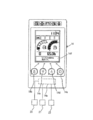
- the monitor buttons described above include a menu button 14b, a content selection / change button 14c, a mode switching button 14d for switching work modes, and a decision button 14e.
- the menu button 14b, the content selection / change button 14c, the mode switching button 14d, or the decision button 14e is operated, the corresponding monitor switch is activated, and a normal screen is displayed on the display unit 14f as shown in FIG. .
- the display on the monitor 14 is displayed as shown in FIG. Part of the specific display on the normal screen of the unit 14f stops.
- Some specific indications include: A / I (auto idle) status displayed in conjunction with the operation of the monitor button enabled when the gate lock lever 13 is raised, work mode status, ML It is a display showing the state of (crane mode).
- the control device 14a includes a key switch determining unit that determines whether or not the key switch 20 is on based on a signal output from the key switch 20, and an engine in a driving state based on a signal output from the rotation speed sensor 21.
- a monitor switch determination unit for determining whether any of the switch of the content selection / change button 14c, the switch of the mode switching button 14d, and the switch of the decision button 14e has been operated.
- the key switch determining unit determines that the key switch 20 is on, the engine driving determining unit determines that the engine is in a driving state, and the gate lock determining unit does not turn off the gate lock switch 22, that is, it is on
- the control device 14a switches the menu button 14b, the content selection / change button 14c, the mode switching button 14d, and the decision button 14e that constitute the monitor switch. As shown in FIG. 4, the operation is disabled, and a part of specific display on the normal screen of the display unit 14 f of the monitor 14 is stopped.
- the control device 14a determines that the key switch 20 is turned on by the key switch determination unit, determines that the engine is in a driving state by the engine drive determination unit, and determines the gate lock switch by the gate lock determination unit.
- a switch of the menu button 14b constituting the monitor switch, a switch of the content selection / change button 14c, and a mode switching button on the display unit 14f of the monitor 14 A warning display indicating that the operation of the switch 14d and the switch of the decision button 14e is invalid, for example, “the monitor SW operation is invalid” is switched to the “partial display” and displayed.
- the controller 14a determines that the key switch 20 is turned on by the key switch determination unit, determines that the engine is in a driving state by the engine drive determination unit, and turns off the gate lock switch 22 in the gate lock determination unit.
- the operation of the switch of the menu button 14b, the switch of the content selection / change button 14c, the switch of the mode switching button 14d, and the switch of the decision button 14e constituting the monitor switch is validated. As shown in FIG. 2, the normal screen is displayed on the display unit 14 f of the monitor 14.
- control device 14a monitors the monitor switch when the key switch 20 is not turned on by the key switch discriminating unit, that is, when the engine drive discriminating unit determines that the engine is not in the driving state.
- the operation of the switch of the menu button 14b, the switch of the content selection / change button 14c, the switch of the mode switching button 14d, and the switch of the decision button 14e is displayed as shown in FIG. Display a normal screen.
- any of the menu button 14b, the content selection / change button 14c, the mode switching button 14d, and the decision button 14e is operated to activate the corresponding monitor switch.
- Step S1 Based on the signal output from the key switch 20, whether or not the key switch 20 is on is determined by the key switch determination unit of the control device 14a. Now, it is determined that the key switch 20 is on, and the process proceeds to step S2. When the key switch determining unit determines that the key switch 20 is not on, that is, off, the process proceeds to step S4.
- Step S2 Based on the signal output from the rotation speed sensor 21 by the engine drive determination unit of the control device 14a, it is determined whether or not the engine is in a driving state. Now, it is determined that the engine is in a driving state, and the process proceeds to step S3. When it is determined that the engine is not in the driving state, the process proceeds to step S4.
- Step S3 Based on a signal output from the gate lock switch 22 by the gate lock determination unit of the control device 14a, it is determined whether or not the gate lock lever 13 is raised and the gate lock switch 22 is in an OFF state. Since the gate lock lever 13 is now raised and the gate lock switch 22 is off, the process proceeds to step S4. When it is determined that the gate lock lever 13 is lowered and the gate lock switch 22 is turned on, the process proceeds to step S6.
- Step S4 One of the switch of the menu button 14b, the switch of the content selection / change button 14c, the switch of the mode switching button 14d, and the switch of the decision button 14e constituting the monitor switch in the monitor switch determination unit of the control device 14a It is determined whether or not an operation has been performed. Now, for example, it is determined that any one of the switch of the menu button 14b, the switch of the content selection / change button 14c, the switch of the mode switching button 14d, and the switch of the decision button 14e is operated, and the process proceeds to step S5. If it is determined that none of the switch of the menu button 14b, the switch of the content selection / change button 14c, the switch of the mode switching button 14d, or the switch of the decision button 14e is operated, the process returns to step S1.
- Step S5 The control device 14a displays according to the operation of the corresponding monitor switch among the switch of the menu button 14b, the switch of the content selection / change button 14c, the switch of the mode switching button 14d, and the switch of the decision button 14e. Is displayed on the display unit 14f of the monitor 14, as shown in FIG.
- step S6 If the engine is driven and the operator seated in the driver's seat 8 lowers the gate lock lever 13 and turns on the gate lock switch 22, that is, allows the supply of pressure oil from the hydraulic pump to the drive circuit, Any of the menu button 14b, the content selection / change button 14c, the mode switching button 14d, and the determination button 14e is operated in a state where the traveling body 1, the revolving body 2, and the work device 3 can be driven. Assume that the switch is activated. At this time, the determination of the gate lock determination unit in step S3 described above becomes no, and the process proceeds to step S6.
- Step S6 The control device 14a generates a warning sound indicating that the operation of the monitor switch is invalid, for example, a buzzer sound. Next, the process proceeds to step S7.
- Step S7 The control device 14a invalidates the operation of all the switches of the menu button 14b, the content selection / change button 14c, the mode switching button 14d, and the decision button 14e that constitute the monitor switch. Then, a specific display of a part of the normal screen on the display unit 14f of the monitor 14 is stopped, and a warning display is performed instead. For example, as shown in FIG. 4, “monitor SW operation is invalid” is displayed on the display unit 14f.
- step S5 and step S7 After the processing of step S5 and step S7, the processing of the control device 14a ends.
- the engine is driven and the gate lock lever 13 is lowered, and the pressure oil from the hydraulic pump drives the driving system such as the traveling body 1, the revolving body 2, and the work device 3.
- the control device 14a switches the menu button 14b, the content selection / change button 14c, the mode switching button 14d, and the decision button 14e that constitute the monitor switch Is disabled, and some specific displays on the normal screen of the monitor 14 are stopped. That is, it is possible to alert the operator that the function of the monitor 14 is limited and the monitor 14 cannot be operated normally.
- the operation of the switch of the menu button 14b, the switch of the content selection / change button 14c, the switch of the mode switching button 14d, and the switch of the decision button 14e constituting the monitor switch is invalidated by the control device 14a.
- a part of specific display on the normal screen of the monitor 14 is stopped, and instead, a warning display indicating invalidity is displayed on the display unit 14f of the monitor 14 to generate a buzzer sound as a warning sound. Therefore, when the engine is driven and the gate lock lever 13 is lowered, it is possible to strongly alert the operator through the eyes and ears that the monitor 14 cannot be operated.
- control device 14a is provided in the monitor 14, but a configuration in which the control device 14a is provided separately from the monitor 14 may be employed.
- the present invention can also be applied to a small construction machine such as a mini excavator provided with a cab.
Landscapes
- Engineering & Computer Science (AREA)
- Mining & Mineral Resources (AREA)
- Civil Engineering (AREA)
- General Engineering & Computer Science (AREA)
- Structural Engineering (AREA)
- Component Parts Of Construction Machinery (AREA)
Applications Claiming Priority (2)
| Application Number | Priority Date | Filing Date | Title |
|---|---|---|---|
| JP2016-186058 | 2016-09-23 | ||
| JP2016186058A JP6577436B2 (ja) | 2016-09-23 | 2016-09-23 | 小型建設機械 |
Publications (1)
| Publication Number | Publication Date |
|---|---|
| WO2018055790A1 true WO2018055790A1 (ja) | 2018-03-29 |
Family
ID=61690874
Family Applications (1)
| Application Number | Title | Priority Date | Filing Date |
|---|---|---|---|
| PCT/JP2017/006682 Ceased WO2018055790A1 (ja) | 2016-09-23 | 2017-02-22 | 小型建設機械 |
Country Status (2)
| Country | Link |
|---|---|
| JP (1) | JP6577436B2 (https=) |
| WO (1) | WO2018055790A1 (https=) |
Families Citing this family (4)
| Publication number | Priority date | Publication date | Assignee | Title |
|---|---|---|---|---|
| WO2021241591A1 (ja) | 2020-05-25 | 2021-12-02 | 住友建機株式会社 | ショベル及びショベルの操作装置 |
| JPWO2022210662A1 (https=) | 2021-03-31 | 2022-10-06 | ||
| JP7853778B2 (ja) * | 2021-11-12 | 2026-04-30 | ヤンマーホールディングス株式会社 | 作業機械の制御方法、作業機械用制御プログラム、作業機械用制御システム及び作業機械 |
| JP2024020856A (ja) | 2022-08-02 | 2024-02-15 | ヤンマーホールディングス株式会社 | 表示装置及び建設機械 |
Citations (3)
| Publication number | Priority date | Publication date | Assignee | Title |
|---|---|---|---|---|
| JP2005068830A (ja) * | 2003-08-25 | 2005-03-17 | Komatsu Ltd | 建設機械 |
| JP2005307483A (ja) * | 2004-04-19 | 2005-11-04 | Hitachi Constr Mach Co Ltd | 建設機械の表示装置 |
| JP2015202841A (ja) * | 2014-04-16 | 2015-11-16 | キャタピラー エス エー アール エル | 作業機械用タッチパネルモニタの入力制御方法 |
Family Cites Families (3)
| Publication number | Priority date | Publication date | Assignee | Title |
|---|---|---|---|---|
| JP4128407B2 (ja) * | 2002-07-25 | 2008-07-30 | 新キャタピラー三菱株式会社 | エンジン装置および作業機械 |
| JP5215805B2 (ja) * | 2008-10-07 | 2013-06-19 | 日立建機株式会社 | 建設機械 |
| DE102009021280A1 (de) * | 2009-05-14 | 2010-11-18 | GM Global Technology Operations, Inc., Detroit | Kraftfahrzeug mit einem Touchpad im Lenkrad und Verfahren zur Ansteuerung des Touchpads |
-
2016
- 2016-09-23 JP JP2016186058A patent/JP6577436B2/ja active Active
-
2017
- 2017-02-22 WO PCT/JP2017/006682 patent/WO2018055790A1/ja not_active Ceased
Patent Citations (3)
| Publication number | Priority date | Publication date | Assignee | Title |
|---|---|---|---|---|
| JP2005068830A (ja) * | 2003-08-25 | 2005-03-17 | Komatsu Ltd | 建設機械 |
| JP2005307483A (ja) * | 2004-04-19 | 2005-11-04 | Hitachi Constr Mach Co Ltd | 建設機械の表示装置 |
| JP2015202841A (ja) * | 2014-04-16 | 2015-11-16 | キャタピラー エス エー アール エル | 作業機械用タッチパネルモニタの入力制御方法 |
Also Published As
| Publication number | Publication date |
|---|---|
| JP6577436B2 (ja) | 2019-09-18 |
| JP2018048530A (ja) | 2018-03-29 |
Similar Documents
| Publication | Publication Date | Title |
|---|---|---|
| US11885108B2 (en) | Work machine and periphery monitoring system | |
| JP5665652B2 (ja) | 建設機械の情報管理装置 | |
| JP4079113B2 (ja) | 建設機械の表示装置 | |
| KR102496324B1 (ko) | 배터리식 작업 기계 | |
| JP6577436B2 (ja) | 小型建設機械 | |
| US11549237B2 (en) | Work vehicle and control system for work vehicle | |
| JPWO2014184978A1 (ja) | 作業車両 | |
| KR102631628B1 (ko) | 작업 기계 | |
| WO2021241591A1 (ja) | ショベル及びショベルの操作装置 | |
| JP4318170B2 (ja) | 建設機械 | |
| JPWO2005054649A1 (ja) | 建設機械 | |
| KR101058463B1 (ko) | 건설 기계의 표시 장치 | |
| JP2015140637A (ja) | 建設機械 | |
| JP4025676B2 (ja) | 作業機械の入力装置 | |
| JP6704879B2 (ja) | 建設機械 | |
| JP7510895B2 (ja) | 作業機械の表示システム | |
| JP5819265B2 (ja) | 建設機械 | |
| WO2023223842A1 (ja) | 作業機械の安全装置 | |
| JP2014105497A (ja) | 建設機械 | |
| JP2022163352A (ja) | 作業機械の制御方法、作業機械用制御プログラム、作業機械用制御システム及び作業機械 | |
| JP2025060281A (ja) | 作業機械 | |
| JP7436301B2 (ja) | 建設機械 | |
| JP2019056218A (ja) | 作業車両 | |
| JP2005068892A (ja) | 建設機械の操作パネル | |
| JP2025152408A (ja) | 建設機械 |
Legal Events
| Date | Code | Title | Description |
|---|---|---|---|
| 121 | Ep: the epo has been informed by wipo that ep was designated in this application |
Ref document number: 17852571 Country of ref document: EP Kind code of ref document: A1 |
|
| NENP | Non-entry into the national phase |
Ref country code: DE |
|
| 122 | Ep: pct application non-entry in european phase |
Ref document number: 17852571 Country of ref document: EP Kind code of ref document: A1 |