WO2018055790A1 - Compact construction machine - Google Patents
Compact construction machine Download PDFInfo
- Publication number
- WO2018055790A1 WO2018055790A1 PCT/JP2017/006682 JP2017006682W WO2018055790A1 WO 2018055790 A1 WO2018055790 A1 WO 2018055790A1 JP 2017006682 W JP2017006682 W JP 2017006682W WO 2018055790 A1 WO2018055790 A1 WO 2018055790A1
- Authority
- WO
- WIPO (PCT)
- Prior art keywords
- gate lock
- switch
- monitor
- engine
- construction machine
- Prior art date
Links
Images


Classifications
-
- E—FIXED CONSTRUCTIONS
- E02—HYDRAULIC ENGINEERING; FOUNDATIONS; SOIL SHIFTING
- E02F—DREDGING; SOIL-SHIFTING
- E02F9/00—Component parts of dredgers or soil-shifting machines, not restricted to one of the kinds covered by groups E02F3/00 - E02F7/00
- E02F9/16—Cabins, platforms, or the like, for drivers
-
- E—FIXED CONSTRUCTIONS
- E02—HYDRAULIC ENGINEERING; FOUNDATIONS; SOIL SHIFTING
- E02F—DREDGING; SOIL-SHIFTING
- E02F9/00—Component parts of dredgers or soil-shifting machines, not restricted to one of the kinds covered by groups E02F3/00 - E02F7/00
- E02F9/26—Indicating devices
Definitions
- the present invention relates to a small-sized construction machine such as a miniature excavator, such as a rear small turning type and an ultra-small turning type excavator, provided with a monitor arranged at the right front of the driver's seat and a gate lock lever arranged at the entrance / exit of the driver's seat.
- a small-sized construction machine such as a miniature excavator, such as a rear small turning type and an ultra-small turning type excavator, provided with a monitor arranged at the right front of the driver's seat and a gate lock lever arranged at the entrance / exit of the driver's seat.
- Patent Document 1 This type of prior art is disclosed in Patent Document 1.
- This prior art is a turning work vehicle that constitutes a small construction machine, and includes a traveling body, a turning body disposed on the traveling body, and a working device attached to the turning body.
- the backward small turning type and the ultra small turning type are formed in a circular shape so that at least the rear end side of the turning body is within the vehicle width of the traveling body.
- a turning work vehicle constituting this type of small construction machine is driven by an engine to drive a drive system such as the traveling body, the turning body, and the working device described above.
- a hydraulic pump for supplying pressure oil to the driving circuit and a pilot pump for supplying operating pressure to the operating device for remotely operating the drive system.
- Patent Document 1 the prior art disclosed in Patent Document 1 is arranged close to the periphery of the driver's seat due to restrictions on the device arrangement space, and each operating lever (operating device) that operates the traveling body, the turning body, and the work device. And a monitor that is disposed in front of the driver's seat and that displays the operating status. Further, a gate lock lever that can be raised and lowered to operate a gate lock switch that outputs a signal for stopping or allowing the supply of the pressure oil from the hydraulic pump to the drive circuit is provided. The gate lock lever is attached so as to be rotatable in the vertical direction with respect to the entrance / exit side on the side of the driver's seat in order to open / close the entrance / exit to the driver's seat in the revolving structure.
- the gate lock switch described above is turned off in conjunction with the raising operation, the supply of pressure oil from the hydraulic pump to the drive circuit is stopped, and the gate lock lever is lowered.
- the aforementioned gate lock switch is turned on to allow the supply of pressure oil from the hydraulic pump to the drive circuit. Therefore, when any one of the operation levers is operated in a state where the gate lock lever is lowered, the pressure oil from the hydraulic pump is supplied to the drive circuit to start the operation.
- an object of the present invention is to provide a small construction machine capable of suppressing malfunction by stopping the screen operation of the monitor with the gate lock lever lowered.
- a small construction machine is provided on a traveling body, a revolving body disposed on the traveling body, a work device attached to the revolving body, and the revolving body.
- Pressure oil is supplied to a driver's seat, an engine compartment that is disposed below the driver's seat and houses an engine, and a driving circuit that is driven by the engine to drive the traveling body, the swivel body, and the working device.
- a hydraulic pump that is disposed around the driver's seat, an operating device that operates the traveling body, the swivel body, and the working device, a monitor that is disposed right in front of the driver's seat, and a swivel body
- a gate lock lever that can be turned up and down to operate a gate lock switch that is arranged at the entrance to the driver's seat and outputs a signal for stopping or allowing the supply of pressure oil from the hydraulic pump to the drive circuit.
- the gate lock lever is lowered while the engine is driven. In this state, the operation of the monitor switch provided in the monitor is invalidated, and at this time, the monitor is provided with a control device for stopping a part of specific display on the normal screen.
- the small construction machine according to the present invention is monitored by the control device when the engine is driven, the gate lock lever is lowered, and the pressure oil from the hydraulic pump can be supplied to the drive circuit that drives the drive system such as the work device.
- the switch operation is invalidated, and some specific displays on the normal screen of the monitor are stopped. That is, it is possible to alert the operator that the monitor function is limited and the monitor cannot be normally operated. As a result, it is possible to suppress the operator's arm or hand from touching the operating device when operating the monitor screen, which could possibly occur in the past, and to prevent malfunctions of the traveling body, the turning body, and the work device.
- FIG. 1 It is a side view which shows the mini excavator which comprises one Embodiment of the small construction machine which concerns on this invention. It is a principal part enlarged view of FIG. It is a figure which shows the monitor with which this embodiment was equipped, and is a front view which shows the state of a monitor switch effective process. It is a figure which shows the monitor with which this embodiment was equipped, and is a front view which shows the state of a monitor switch invalidation process. It is a flowchart which shows the process sequence in the control apparatus provided in the monitor with which this embodiment was equipped.
- the small construction machine includes a canopy-type mini excavator of a small rear turning type formed in a circular shape so that at least the rear end side of the turning body is within the vehicle width of the traveling body. It is configured.
- the revolving body 2 having the above-described cab 7 is disposed on the traveling body 1, and a work device 3 that performs excavation work of soil and the like is attached to the revolving body 2 so as to be rotatable in the vertical direction.
- the work device 3 includes the above-described boom 4 attached to the swing body 2, the arm 5 attached to the tip of the boom 4, and the above-described bucket 6 attached to the tip of the arm 5.
- the working device 3 includes a boom cylinder 4 a that drives the boom 4, an arm cylinder 5 a that drives the arm 5, and a bucket cylinder 6 a that drives the bucket 6.
- a driver's seat 8 on which an operator is seated is disposed in the operator's cab 7.
- an engine room 16 in which an engine is housed is provided in the revolving unit 2 located below the driver's seat 8.
- a counterweight 15 that secures a weight balance is provided at a rear portion of the revolving structure 2.
- a hydraulic pump that supplies pressure oil to a drive circuit that is driven by an engine and drives a drive system such as the traveling body 1, the revolving body 2, and the work device 3, and each operation for remotely operating the drive system
- a pilot pump that supplies the operating pressure of the apparatus is provided in the engine compartment 16.
- operating devices 10 a and 10 b for operating the traveling body 1 are disposed at the front side position of the driver seat 8, and the work device 3 is vertically positioned at the left and right positions of the driver seat 8.
- Operation devices 12a and 12b for rotating the swivel body 2 or turning the revolving body 2 are arranged.
- the operating devices 10a, 10b, 12a, and 12b are arranged close to the periphery of the driver's seat 8 under the restriction of the device arrangement space on the revolving structure that constitutes the rear small turning type.
- a monitor 14 for displaying the operation status is arranged in the front right of the driver's seat 8. Further, a gate lock lever 13 is disposed at the entrance / exit of the driver's seat 8, and a gate for outputting a signal for stopping or allowing the supply of the pressure oil from the hydraulic pump to the drive circuit described above by the gate lock lever 13.
- the lock switch 22 (shown in FIGS. 3 and 4) is operated.
- the gate lock lever 13 is attached to the side of the driver's seat 8 on the side of the driver's seat 8 so as to be able to turn in the vertical direction in order to open and close the entrance / exit to the driver's seat 8 in the revolving structure 2.
- the gate lock switch 22 When the gate lock lever 13 is raised and the entrance is opened, the gate lock switch 22 is turned off in conjunction with the raising operation, the supply of pressure oil from the hydraulic pump to the drive circuit is stopped, and the traveling body 1 and the revolving body 2 and the working device 3 cannot be driven.
- the gate lock switch 22 When the gate lock lever 13 is lowered and the entrance / exit is closed, the gate lock switch 22 is turned on and the supply of pressure oil from the hydraulic pump to the drive circuit is allowed, and the operation devices 10a and 10b and the operation devices 12a and 12b are turned off.
- the traveling body 1, the revolving body 2, and the work device 3 can be driven by operating. Therefore, when any one of the operation devices 10a, 10b, 12a, and 12b is operated in a state where the gate lock lever 13 is lowered, the pressure oil from the hydraulic pump is supplied to the drive circuit and the operation is started.
- the operation of the monitor button for operating the monitor switch for operating the screen provided on the monitor 14 is operated.
- the control device 14a for stopping a part of the specific display although the display (water temperature gauge, fuel gauge, and other important ones) normally necessary for the operation of the mini excavator on the normal screen of the monitor 14 is displayed. It has.
- the control device 14a is provided inside the monitor 14, for example.
- the control device 14a includes a signal output from the key switch 20 that is turned on by inserting and rotating the engine key into the key hole, a signal output from the rotational speed sensor 21 that detects the rotational speed of the engine, The signal output from the gate lock switch 22 described above is input.
- the monitor buttons described above include a menu button 14b, a content selection / change button 14c, a mode switching button 14d for switching work modes, and a decision button 14e.
- the menu button 14b, the content selection / change button 14c, the mode switching button 14d, or the decision button 14e is operated, the corresponding monitor switch is activated, and a normal screen is displayed on the display unit 14f as shown in FIG. .
- the display on the monitor 14 is displayed as shown in FIG. Part of the specific display on the normal screen of the unit 14f stops.
- Some specific indications include: A / I (auto idle) status displayed in conjunction with the operation of the monitor button enabled when the gate lock lever 13 is raised, work mode status, ML It is a display showing the state of (crane mode).
- the control device 14a includes a key switch determining unit that determines whether or not the key switch 20 is on based on a signal output from the key switch 20, and an engine in a driving state based on a signal output from the rotation speed sensor 21.
- a monitor switch determination unit for determining whether any of the switch of the content selection / change button 14c, the switch of the mode switching button 14d, and the switch of the decision button 14e has been operated.
- the key switch determining unit determines that the key switch 20 is on, the engine driving determining unit determines that the engine is in a driving state, and the gate lock determining unit does not turn off the gate lock switch 22, that is, it is on
- the control device 14a switches the menu button 14b, the content selection / change button 14c, the mode switching button 14d, and the decision button 14e that constitute the monitor switch. As shown in FIG. 4, the operation is disabled, and a part of specific display on the normal screen of the display unit 14 f of the monitor 14 is stopped.
- the control device 14a determines that the key switch 20 is turned on by the key switch determination unit, determines that the engine is in a driving state by the engine drive determination unit, and determines the gate lock switch by the gate lock determination unit.
- a switch of the menu button 14b constituting the monitor switch, a switch of the content selection / change button 14c, and a mode switching button on the display unit 14f of the monitor 14 A warning display indicating that the operation of the switch 14d and the switch of the decision button 14e is invalid, for example, “the monitor SW operation is invalid” is switched to the “partial display” and displayed.
- the controller 14a determines that the key switch 20 is turned on by the key switch determination unit, determines that the engine is in a driving state by the engine drive determination unit, and turns off the gate lock switch 22 in the gate lock determination unit.
- the operation of the switch of the menu button 14b, the switch of the content selection / change button 14c, the switch of the mode switching button 14d, and the switch of the decision button 14e constituting the monitor switch is validated. As shown in FIG. 2, the normal screen is displayed on the display unit 14 f of the monitor 14.
- control device 14a monitors the monitor switch when the key switch 20 is not turned on by the key switch discriminating unit, that is, when the engine drive discriminating unit determines that the engine is not in the driving state.
- the operation of the switch of the menu button 14b, the switch of the content selection / change button 14c, the switch of the mode switching button 14d, and the switch of the decision button 14e is displayed as shown in FIG. Display a normal screen.
- any of the menu button 14b, the content selection / change button 14c, the mode switching button 14d, and the decision button 14e is operated to activate the corresponding monitor switch.
- Step S1 Based on the signal output from the key switch 20, whether or not the key switch 20 is on is determined by the key switch determination unit of the control device 14a. Now, it is determined that the key switch 20 is on, and the process proceeds to step S2. When the key switch determining unit determines that the key switch 20 is not on, that is, off, the process proceeds to step S4.
- Step S2 Based on the signal output from the rotation speed sensor 21 by the engine drive determination unit of the control device 14a, it is determined whether or not the engine is in a driving state. Now, it is determined that the engine is in a driving state, and the process proceeds to step S3. When it is determined that the engine is not in the driving state, the process proceeds to step S4.
- Step S3 Based on a signal output from the gate lock switch 22 by the gate lock determination unit of the control device 14a, it is determined whether or not the gate lock lever 13 is raised and the gate lock switch 22 is in an OFF state. Since the gate lock lever 13 is now raised and the gate lock switch 22 is off, the process proceeds to step S4. When it is determined that the gate lock lever 13 is lowered and the gate lock switch 22 is turned on, the process proceeds to step S6.
- Step S4 One of the switch of the menu button 14b, the switch of the content selection / change button 14c, the switch of the mode switching button 14d, and the switch of the decision button 14e constituting the monitor switch in the monitor switch determination unit of the control device 14a It is determined whether or not an operation has been performed. Now, for example, it is determined that any one of the switch of the menu button 14b, the switch of the content selection / change button 14c, the switch of the mode switching button 14d, and the switch of the decision button 14e is operated, and the process proceeds to step S5. If it is determined that none of the switch of the menu button 14b, the switch of the content selection / change button 14c, the switch of the mode switching button 14d, or the switch of the decision button 14e is operated, the process returns to step S1.
- Step S5 The control device 14a displays according to the operation of the corresponding monitor switch among the switch of the menu button 14b, the switch of the content selection / change button 14c, the switch of the mode switching button 14d, and the switch of the decision button 14e. Is displayed on the display unit 14f of the monitor 14, as shown in FIG.
- step S6 If the engine is driven and the operator seated in the driver's seat 8 lowers the gate lock lever 13 and turns on the gate lock switch 22, that is, allows the supply of pressure oil from the hydraulic pump to the drive circuit, Any of the menu button 14b, the content selection / change button 14c, the mode switching button 14d, and the determination button 14e is operated in a state where the traveling body 1, the revolving body 2, and the work device 3 can be driven. Assume that the switch is activated. At this time, the determination of the gate lock determination unit in step S3 described above becomes no, and the process proceeds to step S6.
- Step S6 The control device 14a generates a warning sound indicating that the operation of the monitor switch is invalid, for example, a buzzer sound. Next, the process proceeds to step S7.
- Step S7 The control device 14a invalidates the operation of all the switches of the menu button 14b, the content selection / change button 14c, the mode switching button 14d, and the decision button 14e that constitute the monitor switch. Then, a specific display of a part of the normal screen on the display unit 14f of the monitor 14 is stopped, and a warning display is performed instead. For example, as shown in FIG. 4, “monitor SW operation is invalid” is displayed on the display unit 14f.
- step S5 and step S7 After the processing of step S5 and step S7, the processing of the control device 14a ends.
- the engine is driven and the gate lock lever 13 is lowered, and the pressure oil from the hydraulic pump drives the driving system such as the traveling body 1, the revolving body 2, and the work device 3.
- the control device 14a switches the menu button 14b, the content selection / change button 14c, the mode switching button 14d, and the decision button 14e that constitute the monitor switch Is disabled, and some specific displays on the normal screen of the monitor 14 are stopped. That is, it is possible to alert the operator that the function of the monitor 14 is limited and the monitor 14 cannot be operated normally.
- the operation of the switch of the menu button 14b, the switch of the content selection / change button 14c, the switch of the mode switching button 14d, and the switch of the decision button 14e constituting the monitor switch is invalidated by the control device 14a.
- a part of specific display on the normal screen of the monitor 14 is stopped, and instead, a warning display indicating invalidity is displayed on the display unit 14f of the monitor 14 to generate a buzzer sound as a warning sound. Therefore, when the engine is driven and the gate lock lever 13 is lowered, it is possible to strongly alert the operator through the eyes and ears that the monitor 14 cannot be operated.
- control device 14a is provided in the monitor 14, but a configuration in which the control device 14a is provided separately from the monitor 14 may be employed.
- the present invention can also be applied to a small construction machine such as a mini excavator provided with a cab.
Abstract
In order to stop screen operations on a monitor while a gate lock lever is lowered and suppress operational errors, a compact construction machine according to the present invention is provided with: a monitor 14 disposed to the right and front of a driver's seat 8; and a gate lock lever 13 that when raised, turns off a gate lock switch 22, so that the supply of pressure oil from a hydraulic pump to driving circuits of a traveling body 1, a swing body 2, and a work device 3 is stopped, and when lowered, turns on a gate lock switch 20, so that the supply of the pressure oil from the hydraulic pump to the driving circuits is allowed. The compact construction machine is further provided with a control device 14a that, when the engine is in a driving state and while the gate lock lever 13 is lowered, invalidates the operation of a monitor switch 22 provided on the monitor 14 and stops the specific display of a portion of a normal screen of the monitor 14.
Description
本発明は、運転席の右前方に配置されたモニタと、運転席の乗降口に配置されたゲートロックレバーとを備えている後方小旋回型、超小旋回型のミニショベル等の小型建設機械に関する。
The present invention relates to a small-sized construction machine such as a miniature excavator, such as a rear small turning type and an ultra-small turning type excavator, provided with a monitor arranged at the right front of the driver's seat and a gate lock lever arranged at the entrance / exit of the driver's seat. About.
この種の従来技術が特許文献1に開示されている。この従来技術は、小型建設機械を構成する旋回作業車であり、走行体と、走行体上に配置された旋回体と、この旋回体に取り付けられた作業装置とを備えている。旋回体上には運転席が設けられており、後方小旋回型、超小旋回型を構成するための旋回体上の機器配置スペースの制約を受けて運転席の下方にエンジンが収納されたエンジン室が配置されている。後方小旋回型、超小旋回型は、少なくとも旋回体の後端側が走行体の車幅内に収まるように円形状に形成されている。
This type of prior art is disclosed in Patent Document 1. This prior art is a turning work vehicle that constitutes a small construction machine, and includes a traveling body, a turning body disposed on the traveling body, and a working device attached to the turning body. An engine in which a driver's seat is provided on the swivel body, and the engine is housed below the driver's seat under the restriction of the equipment arrangement space on the swivel body to constitute the rear small turn type and the ultra small turn type The room is located. The backward small turning type and the ultra small turning type are formed in a circular shape so that at least the rear end side of the turning body is within the vehicle width of the traveling body.
なお、特許文献1には示されていないが、この種の小型建設機械を構成する旋回作業車には、エンジンによって駆動されて前述した走行体、旋回体、及び作業装置などの駆動系を駆動する駆動回路に圧油を供給する油圧ポンプ、及び駆動系を遠隔操作するために操作装置に操作圧を供給するパイロットポンプが備えられている。
Although not shown in Patent Document 1, a turning work vehicle constituting this type of small construction machine is driven by an engine to drive a drive system such as the traveling body, the turning body, and the working device described above. There are provided a hydraulic pump for supplying pressure oil to the driving circuit and a pilot pump for supplying operating pressure to the operating device for remotely operating the drive system.
また、特許文献1に開示された従来技術は、機器配置スペースの制約の関係から運転席の周囲に接近して配置され、走行体、旋回体、及び作業装置を操作する各操作レバー(操作装置に含まれる)と、運転席の右前方に配置され稼動状況を表示するモニタとを備えている。また、油圧ポンプから前述した駆動回路への圧油の供給を停止または許容する信号を出力するゲートロックスイッチを操作する上げ下げ可能なゲートロックレバーを備えている。このゲートロックレバーは、旋回体における運転席への乗降口を開閉するために、運転席側方における乗降口側に対して上下方向に回動可能に取り付けられている。
Moreover, the prior art disclosed in Patent Document 1 is arranged close to the periphery of the driver's seat due to restrictions on the device arrangement space, and each operating lever (operating device) that operates the traveling body, the turning body, and the work device. And a monitor that is disposed in front of the driver's seat and that displays the operating status. Further, a gate lock lever that can be raised and lowered to operate a gate lock switch that outputs a signal for stopping or allowing the supply of the pressure oil from the hydraulic pump to the drive circuit is provided. The gate lock lever is attached so as to be rotatable in the vertical direction with respect to the entrance / exit side on the side of the driver's seat in order to open / close the entrance / exit to the driver's seat in the revolving structure.
ゲートロックレバーを上げて乗降口を開けたときには、前述のゲートロックスイッチが上げ動作に連動してオフとなって油圧ポンプから駆動回路への圧油の供給が停止され、ゲートロックレバーを下げて乗降口を閉じたときには、前述のゲートロックスイッチがオンとなって油圧ポンプから駆動回路への圧油の供給が許容される。したがって、ゲートロックレバーが下げられた状態において各操作レバーのいずれかを操作すると、油圧ポンプからの圧油が駆動回路に供給されて作業を開始する。
When the gate lock lever is raised and the entrance is opened, the gate lock switch described above is turned off in conjunction with the raising operation, the supply of pressure oil from the hydraulic pump to the drive circuit is stopped, and the gate lock lever is lowered. When the entrance / exit is closed, the aforementioned gate lock switch is turned on to allow the supply of pressure oil from the hydraulic pump to the drive circuit. Therefore, when any one of the operation levers is operated in a state where the gate lock lever is lowered, the pressure oil from the hydraulic pump is supplied to the drive circuit to start the operation.
前述した特許文献1に開示された従来技術は、ゲートロックレバーが下げられた状態にあるときに、エンジンが駆動されて油圧ポンプからの圧油が駆動回路へ供給される状態になり、運転席に着座したオペレータが運転席の右前方に配置されたモニタの画面を操作するためにモニタに設けられたモニタスイッチを作動させる各種ボタンを操作しようとすると、運転席に接近して配置されている操作レバーに接触する虞がある。なお、小型建設機械にあっては、降車したオペレータがゲートロックレバーが下げられた状態にあるときに、旋回体の脇の位置からモニタの画面操作を行うことがあるが、上記と同様に操作レバーに接触する虞がある。このようにモニタの画面操作時において誤ってオペレータの腕等が操作レバーに接触すると、オペレータが意図しない誤動作を生じる虞がある。
In the prior art disclosed in Patent Document 1 described above, when the gate lock lever is in the lowered state, the engine is driven and the pressure oil from the hydraulic pump is supplied to the drive circuit, and the driver seat When an operator seated in the vehicle tries to operate various buttons for operating a monitor switch provided on the monitor in order to operate a monitor screen arranged on the right front side of the driver's seat, the operator is placed close to the driver's seat. There is a risk of touching the control lever. For small construction machines, when the operator who gets off is in a state where the gate lock lever is lowered, the monitor screen may be operated from the side of the revolving unit. There is a risk of contact with the lever. As described above, if the operator's arm or the like accidentally touches the operation lever during the screen operation of the monitor, there is a risk of causing a malfunction that is not intended by the operator.
上記課題を解決するために、本発明の目的は、ゲートロックレバーを下げた状態でのモニタの画面操作を停止して誤動作を抑制することができる小型建設機械を提供することにある。
In order to solve the above-described problems, an object of the present invention is to provide a small construction machine capable of suppressing malfunction by stopping the screen operation of the monitor with the gate lock lever lowered.
上記課題を解決するために、本発明に係る小型建設機械は、走行体と、走行体上に配置された旋回体と、前記旋回体に取り付けられた作業装置と、旋回体上に設けられた運転席と、前記運転席の下方に配置されてエンジンが収納されるエンジン室と、前記エンジンによって駆動されて前記走行体、前記旋回体、及び前記作業装置を駆動する駆動回路に圧油を供給する油圧ポンプと、前記運転席の周囲に配置されて前記走行体、前記旋回体、及び前記作業装置を操作する操作装置と、前記運転席の右前方に配置されたモニタと、旋回体上における前記運転席への乗降口に配置されて前記油圧ポンプから前記駆動回路への圧油の供給を停止または許容する信号を出力するゲートロックスイッチを操作する上下方向に回動可能なゲートロックレバーとを備えており、前記ゲートロックレバーが上げられたときには、前記ゲートロックスイッチがオフとなって前記油圧ポンプから前記駆動回路への圧油の供給が停止され、前記ゲートロックレバーが下げられたときには、前記ゲートロックスイッチがオンとなって前記油圧ポンプから前記駆動回路への圧油の供給が許容される小型建設機械において、前記エンジンの駆動状態にあって、前記ゲートロックレバーが下げられた状態にあるとき、前記モニタに設けられたモニタスイッチの操作を無効としており、このときに前記モニタには正常画面における一部の特定の表示を停止させる制御装置を備えることを特徴としている。
In order to solve the above problems, a small construction machine according to the present invention is provided on a traveling body, a revolving body disposed on the traveling body, a work device attached to the revolving body, and the revolving body. Pressure oil is supplied to a driver's seat, an engine compartment that is disposed below the driver's seat and houses an engine, and a driving circuit that is driven by the engine to drive the traveling body, the swivel body, and the working device. A hydraulic pump that is disposed around the driver's seat, an operating device that operates the traveling body, the swivel body, and the working device, a monitor that is disposed right in front of the driver's seat, and a swivel body A gate lock lever that can be turned up and down to operate a gate lock switch that is arranged at the entrance to the driver's seat and outputs a signal for stopping or allowing the supply of pressure oil from the hydraulic pump to the drive circuit. When the gate lock lever is raised, the gate lock switch is turned off, the supply of pressure oil from the hydraulic pump to the drive circuit is stopped, and the gate lock lever is lowered. Sometimes, in a small construction machine in which the gate lock switch is turned on and pressure oil is allowed to be supplied from the hydraulic pump to the drive circuit, the gate lock lever is lowered while the engine is driven. In this state, the operation of the monitor switch provided in the monitor is invalidated, and at this time, the monitor is provided with a control device for stopping a part of specific display on the normal screen.
本発明に係る小型建設機械は、エンジンが駆動されてゲートロックレバーが下げられ、油圧ポンプからの圧油が作業装置などの駆動系を駆動する駆動回路に供給可能な状態では、制御装置によりモニタスイッチの操作を無効にし、かつモニタの正常画面における一部の特定の表示が停止する。すなわちモニタとしての機能が制限された状態となってモニタを正常に操作できないことをオペレータに注意喚起することができる。これにより従来では生じる虞のあったモニタの画面操作時のオペレータの腕や手が操作装置へ接触することが抑えられ、走行体、旋回体、及び作業装置の誤動作を抑制することができる。
The small construction machine according to the present invention is monitored by the control device when the engine is driven, the gate lock lever is lowered, and the pressure oil from the hydraulic pump can be supplied to the drive circuit that drives the drive system such as the work device. The switch operation is invalidated, and some specific displays on the normal screen of the monitor are stopped. That is, it is possible to alert the operator that the monitor function is limited and the monitor cannot be normally operated. As a result, it is possible to suppress the operator's arm or hand from touching the operating device when operating the monitor screen, which could possibly occur in the past, and to prevent malfunctions of the traveling body, the turning body, and the work device.
以下、本発明に係る小型建設機械の実施の形態を図面に基づいて説明する。
Hereinafter, embodiments of a small construction machine according to the present invention will be described with reference to the drawings.
図1に示すように本実施形態に係る小型建設機械は、少なくとも旋回体の後端側が走行体の車幅内に収まるように円形状に形成された後方小旋回型のキャノピタイプのミニショベルから構成されている。
As shown in FIG. 1, the small construction machine according to the present embodiment includes a canopy-type mini excavator of a small rear turning type formed in a circular shape so that at least the rear end side of the turning body is within the vehicle width of the traveling body. It is configured.
走行体1の上に前述した運転室7を有する旋回体2が配置され、旋回体2に上下方向の回動可能に土砂の掘削作業等を行う作業装置3が取り付けられている。作業装置3は、旋回体2に取り付けられた前述のブーム4と、このブーム4の先端に取り付けられたアーム5と、このアーム5の先端に取り付けられた前述のバケット6とを含んでいる。また、この作業装置3は、ブーム4を駆動するブームシリンダ4aと、アーム5を駆動するアームシリンダ5aと、バケット6を駆動するバケットシリンダ6aとを含んでいる。
The revolving body 2 having the above-described cab 7 is disposed on the traveling body 1, and a work device 3 that performs excavation work of soil and the like is attached to the revolving body 2 so as to be rotatable in the vertical direction. The work device 3 includes the above-described boom 4 attached to the swing body 2, the arm 5 attached to the tip of the boom 4, and the above-described bucket 6 attached to the tip of the arm 5. The working device 3 includes a boom cylinder 4 a that drives the boom 4, an arm cylinder 5 a that drives the arm 5, and a bucket cylinder 6 a that drives the bucket 6.
図2にも示すように、運転室7内には、オペレータが着座する運転席8が配置されている。運転席8の下方に位置する旋回体2の部分には、図1に示すように、エンジンが収納されたエンジン室16が設けられている。旋回体2の後方部分には、重量バランスを確保するカウンターウエイト15が設けられている。
As shown in FIG. 2, a driver's seat 8 on which an operator is seated is disposed in the operator's cab 7. As shown in FIG. 1, an engine room 16 in which an engine is housed is provided in the revolving unit 2 located below the driver's seat 8. A counterweight 15 that secures a weight balance is provided at a rear portion of the revolving structure 2.
図示しないが、エンジンによって駆動されて走行体1、旋回体2、及び作業装置3などの駆動系を駆動する駆動回路に圧油を供給する油圧ポンプ、及び駆動系を遠隔操作するために各操作装置の操作圧を供給するパイロットポンプが、エンジン室16内に設けられている。
Although not shown in the drawings, a hydraulic pump that supplies pressure oil to a drive circuit that is driven by an engine and drives a drive system such as the traveling body 1, the revolving body 2, and the work device 3, and each operation for remotely operating the drive system A pilot pump that supplies the operating pressure of the apparatus is provided in the engine compartment 16.
図2に示すように、運転席8の前側位置には、走行体1を走行操作する操作装置10a,10bが配置されており、運転席8の左右位置には、作業装置3を上下方向に回動操作させる、あるいは旋回体2を旋回操作させる操作装置12a,12bが配置されている。すなわち、当該後方小旋回型を構成する旋回体上の機器配置スペースの制約を受けて、運転席8の周囲に接近させて操作装置10a,10b,12a,12bが配置されている。
As shown in FIG. 2, operating devices 10 a and 10 b for operating the traveling body 1 are disposed at the front side position of the driver seat 8, and the work device 3 is vertically positioned at the left and right positions of the driver seat 8. Operation devices 12a and 12b for rotating the swivel body 2 or turning the revolving body 2 are arranged. In other words, the operating devices 10a, 10b, 12a, and 12b are arranged close to the periphery of the driver's seat 8 under the restriction of the device arrangement space on the revolving structure that constitutes the rear small turning type.
運転席8の右前方には、稼動状況を表示するモニタ14が配置されている。また、運転席8の乗降口には、ゲートロックレバー13が配置されており、このゲートロックレバー13により油圧ポンプから前述した駆動回路への圧油の供給を停止または許容する信号を出力するゲートロックスイッチ22(図3及び図4に示す)を操作する。ゲートロックレバー13は、旋回体2における運転席8への乗降口を開閉するために、運転席8の側方における乗降口側に対して上下方向に回動可能に取り付けられている。
In the front right of the driver's seat 8, a monitor 14 for displaying the operation status is arranged. Further, a gate lock lever 13 is disposed at the entrance / exit of the driver's seat 8, and a gate for outputting a signal for stopping or allowing the supply of the pressure oil from the hydraulic pump to the drive circuit described above by the gate lock lever 13. The lock switch 22 (shown in FIGS. 3 and 4) is operated. The gate lock lever 13 is attached to the side of the driver's seat 8 on the side of the driver's seat 8 so as to be able to turn in the vertical direction in order to open and close the entrance / exit to the driver's seat 8 in the revolving structure 2.
ゲートロックレバー13を上げて乗降口を開けたときには、ゲートロックスイッチ22が上げ動作に連動してオフとなり、油圧ポンプから駆動回路への圧油の供給が停止されて、走行体1、旋回体2、及び作業装置3が駆動できない状態となる。ゲートロックレバー13を下げて乗降口を閉じたときには、ゲートロックスイッチ22がオンとなり、油圧ポンプから駆動回路への圧油の供給が許容されて、操作装置10a,10b及び操作装置12a,12bを操作して走行体1、旋回体2、及び作業装置3の駆動が可能となる。したがって、ゲートロックレバー13が下げられた状態において操作装置10a,10b,12a,12bのいずれかを操作すると油圧ポンプからの圧油が駆動回路に供給されて作業が開始する。
When the gate lock lever 13 is raised and the entrance is opened, the gate lock switch 22 is turned off in conjunction with the raising operation, the supply of pressure oil from the hydraulic pump to the drive circuit is stopped, and the traveling body 1 and the revolving body 2 and the working device 3 cannot be driven. When the gate lock lever 13 is lowered and the entrance / exit is closed, the gate lock switch 22 is turned on and the supply of pressure oil from the hydraulic pump to the drive circuit is allowed, and the operation devices 10a and 10b and the operation devices 12a and 12b are turned off. The traveling body 1, the revolving body 2, and the work device 3 can be driven by operating. Therefore, when any one of the operation devices 10a, 10b, 12a, and 12b is operated in a state where the gate lock lever 13 is lowered, the pressure oil from the hydraulic pump is supplied to the drive circuit and the operation is started.
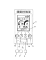
図3、図4に示すように、エンジンの駆動状態にあって、ゲートロックレバー13が下げられた状態にあるとき、モニタ14に設けられた画面操作を行うモニタスイッチを作動させるモニタボタンの操作を無効として、モニタ14の正常画面におけるミニショベルの作業で通常必要な表示(水温計、燃料計、その他の重要なもの)は表示されるものの、一部の特定の表示を停止させる制御装置14aを備えている。この制御装置14aは、例えばモニタ14の内部に設けられている。制御装置14aには、キー穴へのエンジンキーの挿入、回動操作によってオンとなるキースイッチ20から出力された信号と、エンジンの回転数を検出する回転数センサ21から出力された信号と、前述したゲートロックスイッチ22から出力された信号とが入力される。
As shown in FIGS. 3 and 4, when the engine is in a driving state and the gate lock lever 13 is in a lowered state, the operation of the monitor button for operating the monitor switch for operating the screen provided on the monitor 14 is operated. The control device 14a for stopping a part of the specific display although the display (water temperature gauge, fuel gauge, and other important ones) normally necessary for the operation of the mini excavator on the normal screen of the monitor 14 is displayed. It has. The control device 14a is provided inside the monitor 14, for example. The control device 14a includes a signal output from the key switch 20 that is turned on by inserting and rotating the engine key into the key hole, a signal output from the rotational speed sensor 21 that detects the rotational speed of the engine, The signal output from the gate lock switch 22 described above is input.
前述したモニタボタンは、メニューボタン14b、内容選択・変更ボタン14c、作業モードを切り替えるモード切替ボタン14d、及び決定ボタン14eを含んでいる。メニューボタン14b、内容選択・変更ボタン14c、モード切替ボタン14d、あるいは決定ボタン14eが操作されると、該当するモニタスイッチが作動し、図3に示すように表示部14fに正常画面が表示される。
The monitor buttons described above include a menu button 14b, a content selection / change button 14c, a mode switching button 14d for switching work modes, and a decision button 14e. When the menu button 14b, the content selection / change button 14c, the mode switching button 14d, or the decision button 14e is operated, the corresponding monitor switch is activated, and a normal screen is displayed on the display unit 14f as shown in FIG. .
なお、制御装置14aによってモニタスイッチを作動させるメニューボタン14b、内容選択・変更ボタン14c、モード切替ボタン14d、及び決定ボタン14eの操作が無効とされると、図4に示すようにモニタ14の表示部14fの正常画面における一部の特定の表示が停止する。一部の特定の表示とは、ゲートロックレバー13を上げた状態で有効となっているモニタボタンの操作に連動して表示されるA/I(オートアイドル)の状態、作業モードの状態、ML(クレーンモード)の状態を表す表示である。
When the operation of the menu button 14b, the content selection / change button 14c, the mode switching button 14d, and the decision button 14e for operating the monitor switch by the control device 14a is invalidated, the display on the monitor 14 is displayed as shown in FIG. Part of the specific display on the normal screen of the unit 14f stops. Some specific indications include: A / I (auto idle) status displayed in conjunction with the operation of the monitor button enabled when the gate lock lever 13 is raised, work mode status, ML It is a display showing the state of (crane mode).
制御装置14aは、キースイッチ20から出力された信号に基づいてキースイッチ20がオンか否か判別するキースイッチ判別部と、回転数センサ21から出力された信号に基づいてエンジンが駆動状態にあるか否か判別するエンジン駆動判別部と、ゲートロックスイッチ22から出力された信号に基づいてゲートロックスイッチ22がオフか否か判別するゲートロック判別部と、モニタスイッチを構成するメニューボタン14bのスイッチ、内容選択・変更ボタン14cのスイッチ、モード切替ボタン14dのスイッチ、及び決定ボタン14eのスイッチのいずれかが操作されたか否か判別するモニタスイッチ判別部とを有している。
The control device 14a includes a key switch determining unit that determines whether or not the key switch 20 is on based on a signal output from the key switch 20, and an engine in a driving state based on a signal output from the rotation speed sensor 21. An engine drive determining unit for determining whether the gate lock switch 22 is off, a gate lock determining unit for determining whether the gate lock switch 22 is off based on a signal output from the gate lock switch 22, and a switch for the menu button 14b constituting the monitor switch And a monitor switch determination unit for determining whether any of the switch of the content selection / change button 14c, the switch of the mode switching button 14d, and the switch of the decision button 14e has been operated.
キースイッチ判別部でキースイッチ20がオンと判別され、エンジン駆動判別部でエンジンが駆動状態にあると判別され、かつ、ゲートロック判別部でゲートロックスイッチ22がオフとなっていない、すなわちオンとなっていると判別されたとき、制御装置14aは、前述したモニタスイッチを構成するメニューボタン14bのスイッチ、内容選択・変更ボタン14cのスイッチ、モード切替ボタン14dのスイッチ、及び決定ボタン14eのスイッチの操作を無効として、図4に示すように、モニタ14の表示部14fの正常画面における一部の特定の表示を停止させる。
The key switch determining unit determines that the key switch 20 is on, the engine driving determining unit determines that the engine is in a driving state, and the gate lock determining unit does not turn off the gate lock switch 22, that is, it is on When it is determined that the control switch 14a has been configured, the control device 14a switches the menu button 14b, the content selection / change button 14c, the mode switching button 14d, and the decision button 14e that constitute the monitor switch. As shown in FIG. 4, the operation is disabled, and a part of specific display on the normal screen of the display unit 14 f of the monitor 14 is stopped.
また、制御装置14aは、前述のようにキースイッチ判別部でキースイッチ20がオンと判別され、エンジン駆動判別部でエンジンが駆動状態にあると判別され、かつ、ゲートロック判別部でゲートロックスイッチ22がオンとなっていると判別されたとき、図4に示すように、モニタ14の表示部14fにモニタスイッチを構成するメニューボタン14bのスイッチ、内容選択・変更ボタン14cのスイッチ、モード切替ボタン14dのスイッチ、及び決定ボタン14eのスイッチの操作が無効である旨の警告表示、例えば「モニタSW操作は無効です。」を上記「一部の特定の表示」の所に切り換えて表示させる。
Further, as described above, the control device 14a determines that the key switch 20 is turned on by the key switch determination unit, determines that the engine is in a driving state by the engine drive determination unit, and determines the gate lock switch by the gate lock determination unit. When it is determined that the switch 22 is turned on, as shown in FIG. 4, a switch of the menu button 14b constituting the monitor switch, a switch of the content selection / change button 14c, and a mode switching button on the display unit 14f of the monitor 14 A warning display indicating that the operation of the switch 14d and the switch of the decision button 14e is invalid, for example, “the monitor SW operation is invalid” is switched to the “partial display” and displayed.
また、制御装置14aは、キースイッチ判断部でキースイッチ20がオンと判別され、エンジン駆動判別部でエンジンが駆動状態にあると判別され、かつ、ゲートロック判別部でゲートロックスイッチ22がオフとなっていると判別されたとき、モニタスイッチを構成するメニューボタン14bのスイッチ、内容選択・変更ボタン14cのスイッチ、モード切替ボタン14dのスイッチ、及び決定ボタン14eのスイッチの操作を有効として、図3に示すように、モニタ14の表示部14fに正常画面を表示させる。
The controller 14a determines that the key switch 20 is turned on by the key switch determination unit, determines that the engine is in a driving state by the engine drive determination unit, and turns off the gate lock switch 22 in the gate lock determination unit. When it is determined that the switch is selected, the operation of the switch of the menu button 14b, the switch of the content selection / change button 14c, the switch of the mode switching button 14d, and the switch of the decision button 14e constituting the monitor switch is validated. As shown in FIG. 2, the normal screen is displayed on the display unit 14 f of the monitor 14.
また、制御装置14aは、キースイッチ判別部でキースイッチ20がオンとなっていない、すなわちオフと判別されたとき、及びエンジン駆動判別部でエンジンが駆動状態にないと判別されたとき、モニタスイッチを構成するメニューボタン14bのスイッチ、内容選択・変更ボタン14cのスイッチ、モード切替ボタン14dのスイッチ、及び決定ボタン14eのスイッチの操作を有効として、図3に示すように、モニタ14の表示部14fに正常画面を表示させる。
Further, the control device 14a monitors the monitor switch when the key switch 20 is not turned on by the key switch discriminating unit, that is, when the engine drive discriminating unit determines that the engine is not in the driving state. As shown in FIG. 3, the operation of the switch of the menu button 14b, the switch of the content selection / change button 14c, the switch of the mode switching button 14d, and the switch of the decision button 14e is displayed as shown in FIG. Display a normal screen.
次に本実施形態に備えられたモニタ14の制御装置14aにおける処理手順を図5のフローチャートに基づいて説明する。
Next, the processing procedure in the control device 14a of the monitor 14 provided in the present embodiment will be described based on the flowchart of FIG.
今例えば、オペレータがゲートロックレバー13を上げ、ゲートロックスイッチ22をオフにした状態で、すなわち油圧ポンプからの圧油の駆動回路への供給が停止されて、走行体1、旋回体2、及び作業装置3の駆動を行なえない状態で、運転席8に着座し、エンジンキーをキー穴に挿入し回動させてエンジンを駆動したものとする。また、このようにゲートロックレバー13を上げた状態で、メニューボタン14b、内容選択・変更ボタン14c、モード切替ボタン14d、及び決定ボタン14eのいずれかを操作して該当するモニタスイッチを作動させたものとする。
Now, for example, when the operator raises the gate lock lever 13 and turns off the gate lock switch 22, that is, the supply of pressure oil from the hydraulic pump to the drive circuit is stopped, the traveling body 1, the revolving body 2, and Assume that the operator is seated in the driver's seat 8 in a state where the work device 3 cannot be driven, and the engine is driven by inserting an engine key into the key hole and turning it. In addition, with the gate lock lever 13 raised as described above, any of the menu button 14b, the content selection / change button 14c, the mode switching button 14d, and the decision button 14e is operated to activate the corresponding monitor switch. Shall.
[ステップS1] キースイッチ20から出力された信号に基づいて、キースイッチ20がオンか否か制御装置14aのキースイッチ判別部で判別される。今は、キースイッチ20がオンと判別され、ステップS2に進む。なお、キースイッチ判別部でキースイッチ20がオンでない、すなわちオフと判別されたときはステップS4に進む。
[Step S1] Based on the signal output from the key switch 20, whether or not the key switch 20 is on is determined by the key switch determination unit of the control device 14a. Now, it is determined that the key switch 20 is on, and the process proceeds to step S2. When the key switch determining unit determines that the key switch 20 is not on, that is, off, the process proceeds to step S4.
[ステップS2] 制御装置14aのエンジン駆動判別部で回転数センサ21から出力された信号に基づいて、エンジンが駆動状態か否か判別される。今は、エンジンが駆動状態と判別され、ステップS3に進む。なお、エンジンが駆動状態にないと判別されたときは、ステップS4に進む。
[Step S2] Based on the signal output from the rotation speed sensor 21 by the engine drive determination unit of the control device 14a, it is determined whether or not the engine is in a driving state. Now, it is determined that the engine is in a driving state, and the process proceeds to step S3. When it is determined that the engine is not in the driving state, the process proceeds to step S4.
[ステップS3] 制御装置14aのゲートロック判別部でゲートロックスイッチ22から出力された信号に基づいて、ゲートロックレバー13が上げられてゲートロックスイッチ22がオフの状態か否か判別される。今はゲートロックレバー13が上げられてゲートロックスイッチ22がオフの状態であることからステップS4に進む。なお、ゲートロックレバー13が下げられてゲートロックスイッチ22がオンと判別されたときは、ステップS6に進む。
[Step S3] Based on a signal output from the gate lock switch 22 by the gate lock determination unit of the control device 14a, it is determined whether or not the gate lock lever 13 is raised and the gate lock switch 22 is in an OFF state. Since the gate lock lever 13 is now raised and the gate lock switch 22 is off, the process proceeds to step S4. When it is determined that the gate lock lever 13 is lowered and the gate lock switch 22 is turned on, the process proceeds to step S6.
[ステップS4] 制御装置14aのモニタスイッチ判別部で、モニタスイッチを構成するメニューボタン14bのスイッチ、内容選択・変更ボタン14cのスイッチ、モード切替ボタン14dのスイッチ、及び決定ボタン14eのスイッチのいずれかが操作されたか否か判別される。今は例えばメニューボタン14bのスイッチ、内容選択・変更ボタン14cのスイッチ、モード切替ボタン14dのスイッチ、及び決定ボタン14eのスイッチのいずれかが操作されたと判別されて、ステップS5に進む。なお、メニューボタン14bのスイッチ、内容選択・変更ボタン14cのスイッチ、モード切替ボタン14dのスイッチ、及び決定ボタン14eのスイッチのいずれも操作されていないと判別されたときは、ステップS1に戻る。
[Step S4] One of the switch of the menu button 14b, the switch of the content selection / change button 14c, the switch of the mode switching button 14d, and the switch of the decision button 14e constituting the monitor switch in the monitor switch determination unit of the control device 14a It is determined whether or not an operation has been performed. Now, for example, it is determined that any one of the switch of the menu button 14b, the switch of the content selection / change button 14c, the switch of the mode switching button 14d, and the switch of the decision button 14e is operated, and the process proceeds to step S5. If it is determined that none of the switch of the menu button 14b, the switch of the content selection / change button 14c, the switch of the mode switching button 14d, or the switch of the decision button 14e is operated, the process returns to step S1.
[ステップS5] 制御装置14aは、メニューボタン14bのスイッチ、内容選択・変更ボタン14cのスイッチ、モード切替ボタン14dのスイッチ、及び決定ボタン14eのスイッチのうちの該当するモニタスイッチの操作に応じた表示を、図3に示すように、モニタ14の表示部14fに表示する。
[Step S5] The control device 14a displays according to the operation of the corresponding monitor switch among the switch of the menu button 14b, the switch of the content selection / change button 14c, the switch of the mode switching button 14d, and the switch of the decision button 14e. Is displayed on the display unit 14f of the monitor 14, as shown in FIG.
なお仮に、エンジンが駆動され、運転席8に着座したオペレータがゲートロックレバー13を下げ、ゲートロックスイッチ22をオンにした状態、すなわち油圧ポンプからの圧油の駆動回路への供給を許容し、走行体1、旋回体2、及び作業装置3の駆動が可能な状態で、メニューボタン14b、内容選択・変更ボタン14c、モード切替ボタン14d、及び決定ボタン14eのいずれかが操作されて該当するモニタスイッチを作動させたものとする。このとき前述したステップS3のゲートロック判別部の判別はノーとなり、ステップS6に進む。
If the engine is driven and the operator seated in the driver's seat 8 lowers the gate lock lever 13 and turns on the gate lock switch 22, that is, allows the supply of pressure oil from the hydraulic pump to the drive circuit, Any of the menu button 14b, the content selection / change button 14c, the mode switching button 14d, and the determination button 14e is operated in a state where the traveling body 1, the revolving body 2, and the work device 3 can be driven. Assume that the switch is activated. At this time, the determination of the gate lock determination unit in step S3 described above becomes no, and the process proceeds to step S6.
[ステップS6] 制御装置14aは、モニタスイッチの操作が無効である旨の警告音、例えばブザー音を発生させる。次にステップS7に進む。
[Step S6] The control device 14a generates a warning sound indicating that the operation of the monitor switch is invalid, for example, a buzzer sound. Next, the process proceeds to step S7.
[ステップS7] 制御装置14aは、モニタスイッチを構成するメニューボタン14bのスイッチ、内容選択・変更ボタン14cのスイッチ、モード切替ボタン14dのスイッチ、及び決定ボタン14eのスイッチの全てのスイッチの操作を無効とし、モニタ14の表示部14fにおける正常画面の一部の特定の表示を停止させ、代わりに警告表示を行う。例えば図4に示すように、「モニタSW操作は無効です。」を表示部14fに表示する。
[Step S7] The control device 14a invalidates the operation of all the switches of the menu button 14b, the content selection / change button 14c, the mode switching button 14d, and the decision button 14e that constitute the monitor switch. Then, a specific display of a part of the normal screen on the display unit 14f of the monitor 14 is stopped, and a warning display is performed instead. For example, as shown in FIG. 4, “monitor SW operation is invalid” is displayed on the display unit 14f.
ステップS5及びステップS7の処理の後は、制御装置14aの処理は終了する。
After the processing of step S5 and step S7, the processing of the control device 14a ends.
以上のように構成した本実施形態にあっては、エンジンが駆動されてゲートロックレバー13が下げられ、油圧ポンプからの圧油が走行体1、旋回体2、及び作業装置3などの駆動系を駆動する駆動回路に供給可能な状態では、制御装置14aにより、モニタスイッチを構成するメニューボタン14bのスイッチ、内容選択・変更ボタン14cのスイッチ、モード切替ボタン14dのスイッチ、及び決定ボタン14eのスイッチの操作を無効にしてモニタ14の正常画面における一部の特定の表示が停止する。すなわちモニタ14としての機能が制限された状態となってモニタ14を正常に操作できないことをオペレータに注意喚起することができる。これにより、モニタ14の画面操作でオペレータの腕や手が操作装置10a,10b,12a,12bへ接触することが抑えられ、走行体1、旋回体2、及び作業装置3の誤動作を抑制することができる。
In the present embodiment configured as described above, the engine is driven and the gate lock lever 13 is lowered, and the pressure oil from the hydraulic pump drives the driving system such as the traveling body 1, the revolving body 2, and the work device 3. In a state in which it can be supplied to the drive circuit that drives the control circuit 14a, the control device 14a switches the menu button 14b, the content selection / change button 14c, the mode switching button 14d, and the decision button 14e that constitute the monitor switch Is disabled, and some specific displays on the normal screen of the monitor 14 are stopped. That is, it is possible to alert the operator that the function of the monitor 14 is limited and the monitor 14 cannot be operated normally. Thereby, it is possible to suppress the operator's arm or hand from touching the operation devices 10a, 10b, 12a, 12b by the screen operation of the monitor 14, and to suppress the malfunction of the traveling body 1, the revolving body 2, and the work device 3. Can do.
また、本実施形態は、制御装置14aによってモニタスイッチを構成するメニューボタン14bのスイッチ、内容選択・変更ボタン14cのスイッチ、モード切替ボタン14dのスイッチ、及び決定ボタン14eのスイッチの操作が無効にされる際に、モニタ14の正常画面における一部の特定の表示を停止させ、これに代えて無効の旨の警告表示をモニタ14の表示部14fに表示させ、警告音であるブザー音を発生させるので、エンジンが駆動されてゲートロックレバー13が下げられた状態では、モニタ14を操作できないことを目と耳を通してオペレータに強く注意喚起することができる。
Further, in this embodiment, the operation of the switch of the menu button 14b, the switch of the content selection / change button 14c, the switch of the mode switching button 14d, and the switch of the decision button 14e constituting the monitor switch is invalidated by the control device 14a. In this case, a part of specific display on the normal screen of the monitor 14 is stopped, and instead, a warning display indicating invalidity is displayed on the display unit 14f of the monitor 14 to generate a buzzer sound as a warning sound. Therefore, when the engine is driven and the gate lock lever 13 is lowered, it is possible to strongly alert the operator through the eyes and ears that the monitor 14 cannot be operated.
なお、前述した実施形態では、制御装置14aをモニタ14の内部に設けたが、モニタ14とは別体に制御装置14aを設けた構成にしてもよい。
In the above-described embodiment, the control device 14a is provided in the monitor 14, but a configuration in which the control device 14a is provided separately from the monitor 14 may be employed.
また、前述した実施形態は、キャノピを備えたミニショベルによって構成されていたが、キャブを備えたミニショベルなどの小型建設機械にも本発明は適用することができる。
Further, although the above-described embodiment is configured by a mini excavator provided with a canopy, the present invention can also be applied to a small construction machine such as a mini excavator provided with a cab.
1 走行体
2 旋回体
3 作業装置
4 ブーム
4a ブームシリンダ
5 アーム
5a アームシリンダ
6 バケット
6a バケットシリンダ
7 運転室
8 運転席
10a 操作装置
10b 操作装置
12a 操作装置
12b 操作装置
13 ゲートロックレバー
14 モニタ
14a 制御装置
14b メニューボタン
14c 内容選択・変更ボタン
14d モード切替ボタン
14e 決定ボタン
14f 表示部
15 カウンターウエイト
16 エンジン室
20 キースイッチ
21 回転数センサ
22 ゲートロックスイッチ DESCRIPTION OFSYMBOLS 1 Traveling body 2 Revolving body 3 Working device 4 Boom 4a Boom cylinder 5 Arm 5a Arm cylinder 6 Bucket 6a Bucket cylinder 7 Driver's cab 8 Driver's seat 10a Operating device 10b Operating device 12a Operating device 12b Operating device 13 Gate lock lever 14 Monitor 14a Control Device 14b Menu button 14c Contents selection / change button 14d Mode switching button 14e Determination button 14f Display unit 15 Counterweight 16 Engine room 20 Key switch 21 Rotation speed sensor 22 Gate lock switch
2 旋回体
3 作業装置
4 ブーム
4a ブームシリンダ
5 アーム
5a アームシリンダ
6 バケット
6a バケットシリンダ
7 運転室
8 運転席
10a 操作装置
10b 操作装置
12a 操作装置
12b 操作装置
13 ゲートロックレバー
14 モニタ
14a 制御装置
14b メニューボタン
14c 内容選択・変更ボタン
14d モード切替ボタン
14e 決定ボタン
14f 表示部
15 カウンターウエイト
16 エンジン室
20 キースイッチ
21 回転数センサ
22 ゲートロックスイッチ DESCRIPTION OF
Claims (5)
- 走行体と、走行体上に配置された旋回体と、前記旋回体に取り付けられた作業装置と、旋回体上に設けられた運転席と、前記運転席の下方に配置されてエンジンが収納されるエンジン室と、前記エンジンによって駆動されて前記走行体、前記旋回体、及び前記作業装置を駆動する駆動回路に圧油を供給する油圧ポンプと、前記運転席の周囲に配置されて前記走行体、前記旋回体、及び前記作業装置を操作する操作装置と、前記運転席の右前方に配置されたモニタと、旋回体上における前記運転席への乗降口に配置されて前記油圧ポンプから前記駆動回路への圧油の供給を停止または許容する信号を出力するゲートロックスイッチを操作する上下方向の回動可能なゲートロックレバーとを備えており、
前記ゲートロックレバーが上げられたときには、前記ゲートロックスイッチがオフとなって前記油圧ポンプから前記駆動回路への圧油の供給が停止され、前記ゲートロックレバーが下げられたときには、前記ゲートロックスイッチがオンとなって前記油圧ポンプから前記駆動回路への圧油の供給が許容される小型建設機械において、
前記エンジンの駆動状態にあって、前記ゲートロックレバーが下げられた状態にあるとき、前記モニタに設けられたモニタスイッチの操作を無効としており、このときに前記モニタには正常画面における一部の特定の表示を停止させる制御装置を備えることを特徴とする小型建設機械。 A traveling body, a revolving body disposed on the traveling body, a working device attached to the revolving body, a driver seat provided on the revolving body, and an engine housed below the driver seat. An engine room, a hydraulic pump that is driven by the engine to supply pressure oil to a driving circuit that drives the traveling body, the swivel body, and the working device, and the traveling body disposed around the driver seat. An operation device for operating the revolving structure and the working device, a monitor disposed on the right front side of the driver's seat, and a drive from the hydraulic pump disposed at the entrance to the driver's seat on the revolving structure. A gate lock lever that can rotate in the vertical direction to operate a gate lock switch that outputs a signal that stops or allows the supply of pressure oil to the circuit,
When the gate lock lever is raised, the gate lock switch is turned off, the supply of pressure oil from the hydraulic pump to the drive circuit is stopped, and when the gate lock lever is lowered, the gate lock switch In a small construction machine that is turned on and is allowed to supply pressure oil from the hydraulic pump to the drive circuit,
When the engine is in a driving state and the gate lock lever is in a lowered state, the operation of a monitor switch provided in the monitor is invalidated. A small construction machine comprising a control device for stopping a specific display. - 請求項1に記載の小型建設機械において、
前記制御装置は、前記エンジンが駆動状態にあるか否かを判別するエンジン駆動判別部と、前記ゲートロックレバーが上げられて前記ゲートロックスイッチがオフとなっているか否か判別するゲートロック判別部とを有しており、
前記エンジン駆動判別部で前記エンジンが駆動状態にあると判別され、かつ、前記ゲートロック判別部で前記ゲートロックスイッチがオフとなっていないと判別れたとき、前記モニタスイッチの操作を無効として前記モニタの正常画面における一部の特定の表示を停止させることを特徴とする小型建設機械。 The small construction machine according to claim 1,
The control device includes an engine drive determining unit that determines whether or not the engine is in a driving state, and a gate lock determining unit that determines whether or not the gate lock switch is turned off by raising the gate lock lever. And
When the engine drive determining unit determines that the engine is in a driving state, and the gate lock determining unit determines that the gate lock switch is not turned off, the operation of the monitor switch is invalidated. A small construction machine characterized by stopping a specific display on a part of a normal screen of a monitor. - 請求項2に記載の小型建設機械において、
前記制御装置は、前記エンジン駆動判別部で前記エンジンが駆動状態にあると判別され、かつ、前記ゲートロック判別部で前記ゲートロックスイッチがオフとなっていないと判別れたとき、前記モニタに前記モニタスイッチの操作が無効である旨を警告表示させることを特徴とする小型建設機械。 The small construction machine according to claim 2,
When the engine drive determining unit determines that the engine is in a driving state, and the gate lock determining unit determines that the gate lock switch is not turned off, A small construction machine that displays a warning that the operation of the monitor switch is invalid. - 請求項2に記載の小型建設機械において、
前記制御装置は、前記エンジン駆動判別部で前記エンジンが駆動状態にあると判別され、かつ、前記ゲートロック判別部で前記ゲートロックスイッチがオフとなっていると判別されたとき、前記モニタスイッチの操作を有効として前記モニタに正常画面を表示させることを特徴とする小型建設機械。 The small construction machine according to claim 2,
When the engine drive determining unit determines that the engine is in a driving state and the gate lock determining unit determines that the gate lock switch is off, the control device A small construction machine characterized in that an operation is validated and a normal screen is displayed on the monitor. - 請求項4に記載の小型建設機械において、
前記制御装置は、前記エンジン駆動判別部で前記エンジンが駆動状態にないと判別されたとき、前記モニタスイッチの操作を有効として前記モニタに正常画面を表示させることを特徴とする小型建設機械。 The small construction machine according to claim 4,
When the engine drive determining unit determines that the engine is not in a driving state, the control device validates the operation of the monitor switch and displays a normal screen on the monitor.
Applications Claiming Priority (2)
| Application Number | Priority Date | Filing Date | Title |
|---|---|---|---|
| JP2016186058A JP6577436B2 (en) | 2016-09-23 | 2016-09-23 | Small construction machinery |
| JP2016-186058 | 2016-09-23 |
Publications (1)
| Publication Number | Publication Date |
|---|---|
| WO2018055790A1 true WO2018055790A1 (en) | 2018-03-29 |
Family
ID=61690874
Family Applications (1)
| Application Number | Title | Priority Date | Filing Date |
|---|---|---|---|
| PCT/JP2017/006682 WO2018055790A1 (en) | 2016-09-23 | 2017-02-22 | Compact construction machine |
Country Status (2)
| Country | Link |
|---|---|
| JP (1) | JP6577436B2 (en) |
| WO (1) | WO2018055790A1 (en) |
Families Citing this family (3)
| Publication number | Priority date | Publication date | Assignee | Title |
|---|---|---|---|---|
| CN115552078A (en) * | 2020-05-25 | 2022-12-30 | 住友建机株式会社 | Shovel and shovel operating device |
| EP4317603A1 (en) * | 2021-03-31 | 2024-02-07 | Sumitomo Construction Machinery Co., Ltd. | Excavator and display device for excavator |
| JP2024020856A (en) | 2022-08-02 | 2024-02-15 | ヤンマーホールディングス株式会社 | Display devices and construction machinery |
Citations (3)
| Publication number | Priority date | Publication date | Assignee | Title |
|---|---|---|---|---|
| JP2005068830A (en) * | 2003-08-25 | 2005-03-17 | Komatsu Ltd | Construction machine |
| JP2005307483A (en) * | 2004-04-19 | 2005-11-04 | Hitachi Constr Mach Co Ltd | Indicating device of construction machinery |
| JP2015202841A (en) * | 2014-04-16 | 2015-11-16 | キャタピラー エス エー アール エル | Input control method of touch panel monitor for work machine |
Family Cites Families (3)
| Publication number | Priority date | Publication date | Assignee | Title |
|---|---|---|---|---|
| JP4128407B2 (en) * | 2002-07-25 | 2008-07-30 | 新キャタピラー三菱株式会社 | Engine device and work machine |
| JP5215805B2 (en) * | 2008-10-07 | 2013-06-19 | 日立建機株式会社 | Construction machinery |
| DE102009021280A1 (en) * | 2009-05-14 | 2010-11-18 | GM Global Technology Operations, Inc., Detroit | Motor vehicle with a touchpad in the steering wheel and method for controlling the touchpad |
-
2016
- 2016-09-23 JP JP2016186058A patent/JP6577436B2/en active Active
-
2017
- 2017-02-22 WO PCT/JP2017/006682 patent/WO2018055790A1/en active Application Filing
Patent Citations (3)
| Publication number | Priority date | Publication date | Assignee | Title |
|---|---|---|---|---|
| JP2005068830A (en) * | 2003-08-25 | 2005-03-17 | Komatsu Ltd | Construction machine |
| JP2005307483A (en) * | 2004-04-19 | 2005-11-04 | Hitachi Constr Mach Co Ltd | Indicating device of construction machinery |
| JP2015202841A (en) * | 2014-04-16 | 2015-11-16 | キャタピラー エス エー アール エル | Input control method of touch panel monitor for work machine |
Also Published As
| Publication number | Publication date |
|---|---|
| JP6577436B2 (en) | 2019-09-18 |
| JP2018048530A (en) | 2018-03-29 |
Similar Documents
| Publication | Publication Date | Title |
|---|---|---|
| JP4079113B2 (en) | Construction machine display device | |
| CN107923155B (en) | Safety device for construction machine | |
| WO2014184978A1 (en) | Utility vehicle | |
| US20080258889A1 (en) | Vehicle with always forward system | |
| US11885108B2 (en) | Work machine and periphery monitoring system | |
| WO2018055790A1 (en) | Compact construction machine | |
| US11549237B2 (en) | Work vehicle and control system for work vehicle | |
| KR102496324B1 (en) | battery operated machine | |
| JP2013007199A (en) | Work vehicle, display unit for work vehicle, and control method of display unit for work vehicle | |
| KR102631628B1 (en) | working machine | |
| KR101058463B1 (en) | Display of construction machinery | |
| JP4318170B2 (en) | Construction machinery | |
| JP2015140637A (en) | construction machinery | |
| JP4025676B2 (en) | Work machine input device | |
| JP2015001071A (en) | Traveling alarm device for construction machine | |
| JP6704879B2 (en) | Construction machinery | |
| WO2021241591A1 (en) | Excavator and excavator operation device | |
| JP5819265B2 (en) | Construction machinery | |
| WO2022176654A1 (en) | Work machine display system | |
| JP7441699B2 (en) | working machine | |
| JP7436301B2 (en) | construction machinery | |
| JP2011137345A (en) | Monitoring device for construction machine | |
| JP2001213198A (en) | Display device for construction machine | |
| JPH11335073A (en) | Safety device for work machine | |
| CN115680055A (en) | Method for controlling work machine, control program for work machine, control system for work machine, and work machine |
Legal Events
| Date | Code | Title | Description |
|---|---|---|---|
| 121 | Ep: the epo has been informed by wipo that ep was designated in this application |
Ref document number: 17852571 Country of ref document: EP Kind code of ref document: A1 |
|
| NENP | Non-entry into the national phase |
Ref country code: DE |
|
| 122 | Ep: pct application non-entry in european phase |
Ref document number: 17852571 Country of ref document: EP Kind code of ref document: A1 |