WO2017203678A1 - 駆動力制御システムの異常診断方法及び異常診断装置 - Google Patents
駆動力制御システムの異常診断方法及び異常診断装置 Download PDFInfo
- Publication number
- WO2017203678A1 WO2017203678A1 PCT/JP2016/065675 JP2016065675W WO2017203678A1 WO 2017203678 A1 WO2017203678 A1 WO 2017203678A1 JP 2016065675 W JP2016065675 W JP 2016065675W WO 2017203678 A1 WO2017203678 A1 WO 2017203678A1
- Authority
- WO
- WIPO (PCT)
- Prior art keywords
- driving force
- target
- engine
- engine torque
- control system
- Prior art date
Links
- 230000005856 abnormality Effects 0.000 title claims abstract description 63
- 238000002405 diagnostic procedure Methods 0.000 title 1
- 230000005540 biological transmission Effects 0.000 claims abstract description 68
- 238000003745 diagnosis Methods 0.000 claims description 32
- 230000002159 abnormal effect Effects 0.000 claims description 11
- 238000012937 correction Methods 0.000 claims description 9
- 238000000034 method Methods 0.000 claims description 9
- 238000004364 calculation method Methods 0.000 description 21
- 230000001133 acceleration Effects 0.000 description 9
- 206010008138 Cerebral venous thrombosis Diseases 0.000 description 6
- 230000000052 comparative effect Effects 0.000 description 6
- 239000000446 fuel Substances 0.000 description 4
- 229910000831 Steel Inorganic materials 0.000 description 3
- 239000010959 steel Substances 0.000 description 3
- 230000001052 transient effect Effects 0.000 description 3
- 230000002411 adverse Effects 0.000 description 2
- 230000003111 delayed effect Effects 0.000 description 2
- 238000010586 diagram Methods 0.000 description 2
- 230000000694 effects Effects 0.000 description 2
- 238000002347 injection Methods 0.000 description 2
- 239000007924 injection Substances 0.000 description 2
- 230000007175 bidirectional communication Effects 0.000 description 1
- 238000002485 combustion reaction Methods 0.000 description 1
- 230000006854 communication Effects 0.000 description 1
- 238000004891 communication Methods 0.000 description 1
- 239000000470 constituent Substances 0.000 description 1
- 230000001276 controlling effect Effects 0.000 description 1
- 230000007423 decrease Effects 0.000 description 1
- 230000003247 decreasing effect Effects 0.000 description 1
- 230000000881 depressing effect Effects 0.000 description 1
- 238000001514 detection method Methods 0.000 description 1
- 238000002474 experimental method Methods 0.000 description 1
- 238000012986 modification Methods 0.000 description 1
- 230000004048 modification Effects 0.000 description 1
- 230000001105 regulatory effect Effects 0.000 description 1
- 238000004088 simulation Methods 0.000 description 1
Images


Classifications
-
- G—PHYSICS
- G07—CHECKING-DEVICES
- G07C—TIME OR ATTENDANCE REGISTERS; REGISTERING OR INDICATING THE WORKING OF MACHINES; GENERATING RANDOM NUMBERS; VOTING OR LOTTERY APPARATUS; ARRANGEMENTS, SYSTEMS OR APPARATUS FOR CHECKING NOT PROVIDED FOR ELSEWHERE
- G07C5/00—Registering or indicating the working of vehicles
- G07C5/08—Registering or indicating performance data other than driving, working, idle, or waiting time, with or without registering driving, working, idle or waiting time
- G07C5/0808—Diagnosing performance data
-
- B—PERFORMING OPERATIONS; TRANSPORTING
- B60—VEHICLES IN GENERAL
- B60W—CONJOINT CONTROL OF VEHICLE SUB-UNITS OF DIFFERENT TYPE OR DIFFERENT FUNCTION; CONTROL SYSTEMS SPECIALLY ADAPTED FOR HYBRID VEHICLES; ROAD VEHICLE DRIVE CONTROL SYSTEMS FOR PURPOSES NOT RELATED TO THE CONTROL OF A PARTICULAR SUB-UNIT
- B60W50/00—Details of control systems for road vehicle drive control not related to the control of a particular sub-unit, e.g. process diagnostic or vehicle driver interfaces
- B60W50/02—Ensuring safety in case of control system failures, e.g. by diagnosing, circumventing or fixing failures
- B60W50/0205—Diagnosing or detecting failures; Failure detection models
-
- B—PERFORMING OPERATIONS; TRANSPORTING
- B60—VEHICLES IN GENERAL
- B60W—CONJOINT CONTROL OF VEHICLE SUB-UNITS OF DIFFERENT TYPE OR DIFFERENT FUNCTION; CONTROL SYSTEMS SPECIALLY ADAPTED FOR HYBRID VEHICLES; ROAD VEHICLE DRIVE CONTROL SYSTEMS FOR PURPOSES NOT RELATED TO THE CONTROL OF A PARTICULAR SUB-UNIT
- B60W10/00—Conjoint control of vehicle sub-units of different type or different function
- B60W10/04—Conjoint control of vehicle sub-units of different type or different function including control of propulsion units
- B60W10/06—Conjoint control of vehicle sub-units of different type or different function including control of propulsion units including control of combustion engines
-
- B—PERFORMING OPERATIONS; TRANSPORTING
- B60—VEHICLES IN GENERAL
- B60W—CONJOINT CONTROL OF VEHICLE SUB-UNITS OF DIFFERENT TYPE OR DIFFERENT FUNCTION; CONTROL SYSTEMS SPECIALLY ADAPTED FOR HYBRID VEHICLES; ROAD VEHICLE DRIVE CONTROL SYSTEMS FOR PURPOSES NOT RELATED TO THE CONTROL OF A PARTICULAR SUB-UNIT
- B60W10/00—Conjoint control of vehicle sub-units of different type or different function
- B60W10/10—Conjoint control of vehicle sub-units of different type or different function including control of change-speed gearings
-
- B—PERFORMING OPERATIONS; TRANSPORTING
- B60—VEHICLES IN GENERAL
- B60W—CONJOINT CONTROL OF VEHICLE SUB-UNITS OF DIFFERENT TYPE OR DIFFERENT FUNCTION; CONTROL SYSTEMS SPECIALLY ADAPTED FOR HYBRID VEHICLES; ROAD VEHICLE DRIVE CONTROL SYSTEMS FOR PURPOSES NOT RELATED TO THE CONTROL OF A PARTICULAR SUB-UNIT
- B60W30/00—Purposes of road vehicle drive control systems not related to the control of a particular sub-unit, e.g. of systems using conjoint control of vehicle sub-units
- B60W30/18—Propelling the vehicle
- B60W30/188—Controlling power parameters of the driveline, e.g. determining the required power
-
- B—PERFORMING OPERATIONS; TRANSPORTING
- B60—VEHICLES IN GENERAL
- B60W—CONJOINT CONTROL OF VEHICLE SUB-UNITS OF DIFFERENT TYPE OR DIFFERENT FUNCTION; CONTROL SYSTEMS SPECIALLY ADAPTED FOR HYBRID VEHICLES; ROAD VEHICLE DRIVE CONTROL SYSTEMS FOR PURPOSES NOT RELATED TO THE CONTROL OF A PARTICULAR SUB-UNIT
- B60W30/00—Purposes of road vehicle drive control systems not related to the control of a particular sub-unit, e.g. of systems using conjoint control of vehicle sub-units
- B60W30/18—Propelling the vehicle
- B60W30/192—Mitigating problems related to power-up or power-down of the driveline, e.g. start-up of a cold engine
- B60W30/194—Mitigating problems related to power-up or power-down of the driveline, e.g. start-up of a cold engine related to low temperature conditions, e.g. high viscosity of hydraulic fluid
-
- B—PERFORMING OPERATIONS; TRANSPORTING
- B60—VEHICLES IN GENERAL
- B60W—CONJOINT CONTROL OF VEHICLE SUB-UNITS OF DIFFERENT TYPE OR DIFFERENT FUNCTION; CONTROL SYSTEMS SPECIALLY ADAPTED FOR HYBRID VEHICLES; ROAD VEHICLE DRIVE CONTROL SYSTEMS FOR PURPOSES NOT RELATED TO THE CONTROL OF A PARTICULAR SUB-UNIT
- B60W50/00—Details of control systems for road vehicle drive control not related to the control of a particular sub-unit, e.g. process diagnostic or vehicle driver interfaces
- B60W50/04—Monitoring the functioning of the control system
- B60W50/045—Monitoring control system parameters
-
- F—MECHANICAL ENGINEERING; LIGHTING; HEATING; WEAPONS; BLASTING
- F02—COMBUSTION ENGINES; HOT-GAS OR COMBUSTION-PRODUCT ENGINE PLANTS
- F02D—CONTROLLING COMBUSTION ENGINES
- F02D29/00—Controlling engines, such controlling being peculiar to the devices driven thereby, the devices being other than parts or accessories essential to engine operation, e.g. controlling of engines by signals external thereto
-
- F—MECHANICAL ENGINEERING; LIGHTING; HEATING; WEAPONS; BLASTING
- F02—COMBUSTION ENGINES; HOT-GAS OR COMBUSTION-PRODUCT ENGINE PLANTS
- F02D—CONTROLLING COMBUSTION ENGINES
- F02D41/00—Electrical control of supply of combustible mixture or its constituents
- F02D41/02—Circuit arrangements for generating control signals
- F02D41/14—Introducing closed-loop corrections
- F02D41/1497—With detection of the mechanical response of the engine
-
- F—MECHANICAL ENGINEERING; LIGHTING; HEATING; WEAPONS; BLASTING
- F02—COMBUSTION ENGINES; HOT-GAS OR COMBUSTION-PRODUCT ENGINE PLANTS
- F02D—CONTROLLING COMBUSTION ENGINES
- F02D41/00—Electrical control of supply of combustible mixture or its constituents
- F02D41/02—Circuit arrangements for generating control signals
- F02D41/18—Circuit arrangements for generating control signals by measuring intake air flow
-
- F—MECHANICAL ENGINEERING; LIGHTING; HEATING; WEAPONS; BLASTING
- F02—COMBUSTION ENGINES; HOT-GAS OR COMBUSTION-PRODUCT ENGINE PLANTS
- F02D—CONTROLLING COMBUSTION ENGINES
- F02D41/00—Electrical control of supply of combustible mixture or its constituents
- F02D41/22—Safety or indicating devices for abnormal conditions
-
- B—PERFORMING OPERATIONS; TRANSPORTING
- B60—VEHICLES IN GENERAL
- B60W—CONJOINT CONTROL OF VEHICLE SUB-UNITS OF DIFFERENT TYPE OR DIFFERENT FUNCTION; CONTROL SYSTEMS SPECIALLY ADAPTED FOR HYBRID VEHICLES; ROAD VEHICLE DRIVE CONTROL SYSTEMS FOR PURPOSES NOT RELATED TO THE CONTROL OF A PARTICULAR SUB-UNIT
- B60W2510/00—Input parameters relating to a particular sub-units
- B60W2510/06—Combustion engines, Gas turbines
- B60W2510/0614—Position of fuel or air injector
- B60W2510/0628—Inlet air flow rate
-
- B—PERFORMING OPERATIONS; TRANSPORTING
- B60—VEHICLES IN GENERAL
- B60W—CONJOINT CONTROL OF VEHICLE SUB-UNITS OF DIFFERENT TYPE OR DIFFERENT FUNCTION; CONTROL SYSTEMS SPECIALLY ADAPTED FOR HYBRID VEHICLES; ROAD VEHICLE DRIVE CONTROL SYSTEMS FOR PURPOSES NOT RELATED TO THE CONTROL OF A PARTICULAR SUB-UNIT
- B60W2510/00—Input parameters relating to a particular sub-units
- B60W2510/06—Combustion engines, Gas turbines
- B60W2510/0676—Engine temperature
-
- F—MECHANICAL ENGINEERING; LIGHTING; HEATING; WEAPONS; BLASTING
- F02—COMBUSTION ENGINES; HOT-GAS OR COMBUSTION-PRODUCT ENGINE PLANTS
- F02D—CONTROLLING COMBUSTION ENGINES
- F02D2200/00—Input parameters for engine control
- F02D2200/02—Input parameters for engine control the parameters being related to the engine
- F02D2200/04—Engine intake system parameters
- F02D2200/0402—Engine intake system parameters the parameter being determined by using a model of the engine intake or its components
-
- F—MECHANICAL ENGINEERING; LIGHTING; HEATING; WEAPONS; BLASTING
- F02—COMBUSTION ENGINES; HOT-GAS OR COMBUSTION-PRODUCT ENGINE PLANTS
- F02D—CONTROLLING COMBUSTION ENGINES
- F02D2200/00—Input parameters for engine control
- F02D2200/02—Input parameters for engine control the parameters being related to the engine
- F02D2200/04—Engine intake system parameters
- F02D2200/0414—Air temperature
-
- F—MECHANICAL ENGINEERING; LIGHTING; HEATING; WEAPONS; BLASTING
- F02—COMBUSTION ENGINES; HOT-GAS OR COMBUSTION-PRODUCT ENGINE PLANTS
- F02D—CONTROLLING COMBUSTION ENGINES
- F02D2200/00—Input parameters for engine control
- F02D2200/02—Input parameters for engine control the parameters being related to the engine
- F02D2200/10—Parameters related to the engine output, e.g. engine torque or engine speed
- F02D2200/1002—Output torque
-
- F—MECHANICAL ENGINEERING; LIGHTING; HEATING; WEAPONS; BLASTING
- F02—COMBUSTION ENGINES; HOT-GAS OR COMBUSTION-PRODUCT ENGINE PLANTS
- F02D—CONTROLLING COMBUSTION ENGINES
- F02D2200/00—Input parameters for engine control
- F02D2200/02—Input parameters for engine control the parameters being related to the engine
- F02D2200/10—Parameters related to the engine output, e.g. engine torque or engine speed
- F02D2200/101—Engine speed
-
- F—MECHANICAL ENGINEERING; LIGHTING; HEATING; WEAPONS; BLASTING
- F02—COMBUSTION ENGINES; HOT-GAS OR COMBUSTION-PRODUCT ENGINE PLANTS
- F02D—CONTROLLING COMBUSTION ENGINES
- F02D2200/00—Input parameters for engine control
- F02D2200/50—Input parameters for engine control said parameters being related to the vehicle or its components
- F02D2200/501—Vehicle speed
Definitions
- the present invention relates to a driving force control system in which an automatic transmission is interposed between an engine and driving wheels, and more particularly to abnormality diagnosis of the driving force control system.
- a target driving force transmitted to a driving wheel is obtained from a driver's output request based on an accelerator opening degree and the vehicle speed, and based on this target driving force.
- a so-called power train torque demand control (PTD control) for controlling an engine and an automatic transmission is known.
- Patent Document 1 as a method of determining an abnormality in a form in which the acceleration of the vehicle becomes too large, the estimated driving force is compared with a threshold value, and the abnormality of the vehicle is determined according to the result. . Further, when the driving force cannot be normally estimated due to an abnormality of the actuator or the like, the abnormality of the vehicle is determined by comparing the estimated engine torque with a threshold value.
- the oil viscosity is high, so the rise of hydraulic pressure supplied to the automatic transmission is insufficient, and the driving force control system including the automatic transmission is normal, There may be a transient response delay of the automatic transmission.
- the abnormality of the driving force control system is determined using the driving force transmitted to the driving wheels, it may be erroneously determined to be abnormal although it is normal due to the response delay of the automatic transmission. There is.
- the present invention has been made in view of such circumstances, and it is erroneously determined to be abnormal although the driving force control system is normal due to a transient response delay of the shift operation by the automatic transmission. This is intended to suppress this and improve the diagnostic accuracy.
- the present invention calculates so-called power train torque demand control (PTD control) that calculates a target driving force transmitted to driving wheels based on a driver output request and controls an automatic transmission and an engine based on the target driving force. ).
- PTD control power train torque demand control
- the driving force control caused by the engine is controlled. It is determined that the system is abnormal.
- the driving force control system adopts PTD control
- the engine torque is used instead of the driving force transmitted to the driving wheel to determine the abnormality in the driving force control system
- the gear ratio of the automatic transmission In a form that eliminates the influence of the above, if a difference exceeding the threshold value occurs between the target engine torque and the actual engine torque, it is determined that there is an abnormality. Therefore, even when the shift operation by the automatic transmission is temporarily delayed during acceleration in a low temperature state, it is possible to accurately determine an abnormality in a manner that eliminates the adverse effects associated with this delay in the shift operation. It becomes.
- the present invention it is possible to suppress an erroneous determination associated with a transient response delay of the shift operation of the automatic transmission and perform an accurate abnormality diagnosis.
- an automatic transmission 13 is interposed between an engine 11 as a vehicle driving source and driving wheels 12, and the automatic transmission 13 and driving wheels 12 are connected via an axle 14. Yes.
- the engine 11 is an internal combustion engine that generates driving force by burning fuel such as gasoline or light oil.
- a motor, a fuel cell, or the like may be used alone or in combination.
- the automatic transmission 13 is a belt type continuously variable transmission capable of continuously and continuously shifting. Since this belt-type continuously variable transmission has a well-known structure, a brief description will be given.
- a steel belt having a number of steel pieces and two steel rings is connected to a primary pulley connected to the engine 11 side and a drive. It spans the secondary pulley connected to the wheel side and changes the contact radius of the belt, thereby changing the gear ratio steplessly.
- the driving force control system connects a plurality of controllers such as the engine control module 21 (ECM) and the transmission control unit 22 (CVT-CU) through a system capable of bidirectional communication such as CAN communication, and shares necessary information. It is possible.
- the engine control module 21 mainly controls the engine 11, and the transmission control unit 22 mainly controls the automatic transmission 13.
- power train control including the engine 11 and the automatic transmission 13 is first transmitted to the driving wheel 12 based on the accelerator pedal opening and the vehicle speed corresponding to the driver's output request.
- the target drive force tFd which is the final target value of the drive force, is calculated and calculated, and the engine 11 and the automatic transmission 13 are controlled based on the target drive force tFd, so-called power train torque demand control ( PTD control).
- a target engine torque tTe that is a target value of the output torque output from the engine 11 and a target speed ratio tRto that is a target value of the speed ratio of the automatic transmission 13 are obtained, and the target The engine 11 is controlled toward the engine torque tTe, and the automatic transmission 13 is controlled toward the target gear ratio tRto.
- the accelerator opening for example, a signal of an accelerator opening sensor that detects the opening of an accelerator pedal is used.
- the vehicle speed is detected by a vehicle speed sensor.
- the vehicle speed may be estimated using the input rotational speed (engine rotational speed) of the automatic transmission and the gear ratio.
- the target driving force calculation unit 23 calculates the target driving force tFd based on the accelerator opening and the vehicle speed.
- the target input speed calculation unit 24 calculates a target input speed tNi that is a target value of the input speed (that is, engine speed) of the automatic transmission 13 based on the target driving force tFd.
- the correction term calculation unit 25 obtains a correction term for realizing other performance requirements such as driving of auxiliary machines.
- the upper limit of engine torque is regulated so as to be equal to or less than a predetermined value. In other words, by making a correction so that the target driving force tFd is not excessively different from the original value (tFd ′) due to the correction by the correction term calculation unit 25, a misdiagnosis occurs due to the correction by the correction term calculation unit 25. Has been prevented.
- the target engine torque calculation unit 27 calculates the target engine torque tTe based on the target input rotation speed tNi (engine rotation speed) within the range limited by the torque limit unit 26, and outputs this to the engine control unit 28. . That is, the target engine torque tTe is calculated so that the engine speed becomes the target input speed tNi.
- the engine control unit 28 controls the throttle opening (in the case of a gasoline engine) or the fuel injection amount (in the case of a diesel engine) based on the target engine torque tTe.
- the target gear ratio calculation unit 31 the target gear ratio tRto corresponding to the target value of the gear ratio of the automatic transmission 13 is determined from the target input rotation speed tNi and the vehicle speed. Calculate.
- the shift control unit 32 performs shift control of the automatic transmission 13 based on the target speed ratio tRto.
- the shift speed control unit 33 controls the shift speed by the shift control unit 32.
- the automatic transmission (CVT) 13 is provided with a rotation sensor for detecting the rotational speed of the shaft on the input side and output side of the automatic transmission (CVT) 13, and the CVT diagnosis unit 34 detects, for example, the detected input side with respect to the target gear ratio tRto.
- the actual transmission ratio calculated from the shaft speed on the output side is compared, and if the difference is within a predetermined range, it is determined that the automatic transmission 13 is operating normally. Note that it may be determined whether the operation is normal including other diagnoses.
- the control contents of the abnormality determination unit 35 provided in the engine control module 21 will be described.
- the CVT diagnosis unit 34 determines whether the automatic transmission 13 is operating normally so as to suppress misdiagnosis caused by a temporary response delay of the shift operation.
- the abnormality of the driving force control system caused by the engine 11 is determined.
- the sub target driving force calculation unit 23A calculates the target driving force tFd 'based on the accelerator opening and the vehicle speed, as in the target driving force calculation unit 23 described above.
- the sub target driving force calculation unit 23A is provided and the target driving force tFd ′ used for abnormality diagnosis is obtained separately.
- the sub target driving force calculation unit 23A is omitted, and the above target driving force is calculated. You may make it use tFd for abnormality diagnosis as it is.
- the target input rotational speed tNi ′ is calculated.
- the sub target input speed calculator 24A may be omitted, and the target input speed tNi obtained by the target input speed calculator 24 may be used for abnormality diagnosis.
- the sub target engine torque calculation unit 27A calculates the target engine torque tTe 'based on the target driving force tFd', the target input rotational speed tNi ', and the like.
- the sub target engine torque calculation unit 27A may be omitted, and the target engine torque tTe obtained by the target engine torque calculation unit 27 may be used for abnormality diagnosis.
- the actual engine torque detector 36 detects an actual engine torque rTe ′ that is an output torque of the engine 11.
- the actual engine torque rTe ′ is obtained by taking into consideration the ignition timing, EGR rate, and fuel injection timing in addition to the intake air amount detected by, for example, an air flow meter.
- the torque comparison unit 38 compares the actual engine torque rTe ′ and the target engine torque tTe ′, and when there is a difference exceeding a predetermined threshold value sTe between them, the driving force caused by the engine 11 It is determined that the control system is abnormal. Specifically, a predetermined diagnostic threshold value sTe is added to the target engine torque tTe ′, and this added value (tTe ′ + sTe) is compared with the actual engine torque rTe ′. If the actual engine torque rTe ′ exceeds the above added value (tTe ′ + sTe), it is determined that there is an abnormality.
- a predetermined diagnostic threshold value sTe is added to the target engine torque tTe ′, and this added value (tTe ′ + sTe) is compared with the actual engine torque rTe ′. If the actual engine torque rTe ′ exceeds the above added value (tTe ′ + sTe), it
- the fail-safe operation mode is implemented according to the abnormality diagnosis code stored in this manner, or the abnormality is notified to the passenger by display or voice.
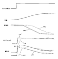
- the threshold value sTe is a difference generated between the target engine torque tTe ′ and the actual engine torque rTe ′ when an abnormality of the driving force control system caused by the engine such as a throttle failure or a calculation value abnormality occurs. Is a value set in advance by experiment or simulation. As shown in FIG. 2, the actual engine torque rTe ′ fluctuates slightly with respect to the target engine torque tTe ′ even in a normal vehicle operation state. As described above, the threshold value sTe is determined by the driver as a fail-safe when a MIN value that secures a certain level of magnitude and a driving torque larger than a vehicle request is generated due to an abnormality in the driving force control system.
- a MAX value that ensures a small size (for example, 0.2 G in acceleration) that can be dealt with with a margin by a brake or the like.
- the abnormality in the driving force control system caused by such an engine is surely diagnosed as an abnormality. It is set as a value smaller than the difference (absolute value) between the target engine torque tTe ′ and the actual engine torque rTe ′ that occur in this case.
- the threshold value sTe (absolute value) with respect to the target engine torque tTe ′ is used to determine an abnormality in which the actual engine torque rTe ′ is excessively larger than the target engine torque tTe ′. Is added and (tTe ′ + sTe) is determined to be abnormal when the actual engine torque rTe ′ exceeds the actual engine torque rTe ′, but the actual engine torque rTe ′ is excessively smaller than the target engine torque tTe ′. It is also possible to determine a form abnormality.
- the threshold value sTe (positive value) is subtracted from the target engine torque tTe ′, and when the actual engine torque rTe ′ is below the subtracted value (tTe′ ⁇ sTe), it is determined that there is an abnormality. . Further, a combination of the two may be used to determine whether the actual engine torque rTe ′ is excessively large or excessively small with respect to the target engine torque tTe ′.
- the torque comparison unit 38 detects or estimates the intake air temperature of the engine so that the abnormality diagnosis is not erroneously performed due to variations in the engine torque in the extremely low temperature state, and based on the intake air temperature. To correct the abnormality diagnosis determination process. Specifically, when the intake air temperature is extremely low, the diagnostic threshold value sTe is large in order to prevent erroneous determination as abnormal even though the driving force control system is normal. The correction is made in the direction. That is, the target engine torque tTe ′ or the threshold value sTe is corrected to the increasing side, or the actual engine torque rTe ′ is corrected to the decreasing side.
- FIG. 3 and 4 show an abnormality diagnosis device for a driving force control system according to a comparative example.
- the same constituent elements as those in the first embodiment are denoted by the same reference numerals, and redundant description will be omitted as appropriate.
- the actual gear ratio rRto ' is detected or estimated, and the actual driving force calculation unit 41 obtains the actual driving force rFd' based on the actual engine torque rTe 'and the actual gear ratio rRto'.
- the driving force diagnosis unit 42 performs an abnormality diagnosis based on a comparison between the actual driving force rFd 'and the target driving force tFd'. Specifically, as shown in FIG. 4, a value (tFd ′ + sFd) obtained by adding the target driving force tFd and a preset diagnostic threshold value sFd is compared with the actual driving force rFd ′. An abnormality is diagnosed when the driving force rFd ′ exceeds the added value (tFd ′ + sFd).
- the vehicle speed increases and the gear ratio decreases.
- the rise of the hydraulic pressure supplied to the primary side of the automatic transmission 13 at a low temperature is delayed, and thus the actual transmission ratio rRto ′ is transiently changed to the target transmission ratio tRto ′ while the automatic transmission 13 itself is normal. May deviate from.
- the target speed ratio tRto ′ is used for calculating the target driving force tFd ′
- the actual speed ratio rRto ′ is used for calculating the actual driving force rFd ′.
- the driving force control system including the engine 11 and the automatic transmission 13 is operating normally due to the influence of the difference between the actual transmission ratio rRto ′ and the target transmission ratio tRto ′, the actual driving force rFd ′.
- Exceeds the added value (tFd ′ + sFd) and there is a risk of erroneous diagnosis as abnormal.
- the vehicle employs power train torque demand control (PTD control) using the target driving force
- the engine torque not the driving force
- PTD control power train torque demand control
- the engine torque is used for abnormality diagnosis. Is diagnosed based on a comparison between the target engine torque tTe ′ and the actual engine torque rTe ′, and the actual gear ratio rRto ′ is used to calculate the target engine torque tTe ′ and the actual engine torque rTe ′. Therefore, diagnosis can be performed in a manner that eliminates the adverse effects of the gear ratio.
- FIG. 5 is a flowchart showing the control flow of the abnormality diagnosis of this embodiment, and this routine is repeatedly executed every extremely short period (for example, 10 ms).
- step S11 the CVT diagnosis unit 34 determines whether the automatic transmission 13 is normal. This determination is provided on the input side and output side of the automatic transmission 13 with a rotation sensor for detecting the shaft speed, and is calculated from the detected shaft speed on the input side and output side with respect to the target speed ratio tRto. The actual transmission ratios are compared, and if the difference is within a predetermined range, it is determined that the automatic transmission 13 is operating normally. Note that it may be determined whether the operation is normal including other diagnoses. The determination result of the abnormality determination of the automatic transmission is output as a flag. If the automatic transmission 13 is not normal, the process proceeds to step S12, the corresponding error code is output, and this routine is terminated.
- step S13 the target engine torque tTe 'is calculated by the sub engine torque calculator 27A.
- step S ⁇ b> 14 the actual engine torque detection unit 36 detects the actual engine torque rTe ′.
- step S15 the torque comparison unit 38 determines whether a difference exceeding a predetermined threshold value sTe has occurred between the target engine torque tTe and the actual engine torque rTe '. If a difference has occurred, it is determined that there is an abnormality, and the process proceeds to step S16, a corresponding error code is output, and this routine is terminated.
- the abnormality of the driving force control system is determined based on the engine torque, so that the speed change operation in the normal automatic transmission 13 is temporarily performed. It can be reliably suppressed that an abnormality is diagnosed with a response delay.
- the solid line represents the target value (or addition value), and the broken line represents the estimated value (actual gear range, actual gear ratio, actual engine torque).
- a belt-type continuously variable transmission is used as the automatic transmission 13.
- a stepped automatic transmission is used as the automatic transmission 13.
- the automatic transmission 13 itself is in a normal state while the vehicle is accelerating. Therefore, the actual speed ratio rRto ′ may greatly deviate from the target speed ratio tRto ′.
- the actual gear range may not move according to the target gear range even if a failure is excluded.
- the transmission control unit 22 temporarily ignores the request from the engine control module 21 to protect the unit, or when the hydraulic pressure is not sufficient for the automatic transmission to perform a shift. .
- abnormality diagnosis is performed based on the engine torque, and the influence of the gear ratio is eliminated, so that the actual gear ratio rRto is temporarily set with respect to the target gear ratio tRto ′. Even if 'is temporarily deviated, the actual engine torque rTe' is not greatly deviated from the added value (tTe '+ sTe), and the accuracy of diagnosis can be improved by suppressing or avoiding the situation of misjudging an abnormality. Can do.
- the present invention has been described based on specific examples. However, the present invention is not limited to the above-described examples, and includes various modifications and changes.
- the present invention is applied to an abnormality in which the acceleration is larger than the target.
- the present invention may be applied to an abnormality in which the deceleration is smaller than the target. Is possible.
Landscapes
- Engineering & Computer Science (AREA)
- Mechanical Engineering (AREA)
- Combustion & Propulsion (AREA)
- Chemical & Material Sciences (AREA)
- Transportation (AREA)
- Automation & Control Theory (AREA)
- General Engineering & Computer Science (AREA)
- Human Computer Interaction (AREA)
- Physics & Mathematics (AREA)
- General Physics & Mathematics (AREA)
- Control Of Transmission Device (AREA)
- Control Of Vehicle Engines Or Engines For Specific Uses (AREA)
- Combined Controls Of Internal Combustion Engines (AREA)
- Control Of Driving Devices And Active Controlling Of Vehicle (AREA)
Abstract
運転者出力要求としてのアクセル開度と車速とに基づいて、駆動輪(12)に伝達される駆動力の目標値に対応する目標駆動力(tFd')を算出し、この目標駆動力(tFd)に基づいて、自動変速機の変速比の目標値に対応する目標変速比(tRto)と、エンジンの出力トルクの目標値に対応する目標エンジントルク(tTe)と、を算出する。エンジンの出力トルクに対応する実エンジントルク(rTe')を検出もしくは推定し、目標エンジントルク(tTe')と実エンジントルク(rTe')とに基づいて、エンジン11に起因する駆動力制御システムの異常であるか否かを判定する。
Description
本発明は、エンジンと駆動輪との間に自動変速機を介装した駆動力制御システムに関し、特に、駆動力制御システムの異常診断に関する。
特許文献1に記載されているように、駆動力制御システムとして、アクセル開度等による運転者の出力要求と車速とから駆動輪に伝達される目標駆動力を求め、この目標駆動力に基づいてエンジンと自動変速機とを制御する、いわゆるパワートレーントルクデマンド制御(PTD制御)が知られている。
また、特許文献1には、車両の加速度が大きくなり過ぎる形態の異常を判定する手法として、推定された駆動力としきい値とを比較し、その結果に応じて車両の異常を判定している。更に、アクチュエータの異常等により駆動力を正常に推定できない異常時には、推定されたエンジントルクとしきい値とを比較することにより車両の異常を判定している。
例えば低温状態での加速時では、オイルの粘度が高いことから、自動変速機へ供給される油圧の立ち上がりが不足し、自動変速機を含めた駆動力制御システムが正常であるにもかかわらず、過渡的に自動変速機による変速の応答遅れを生じることがある。このような場合に、駆動輪に伝達される駆動力を用いて駆動力制御システムの異常を判定した場合、自動変速機の応答遅れによって、正常であるにもかかわらず異常と誤判定されるおそれがある。
本発明は、このような事情に鑑みてなされたものであり、自動変速機による変速動作の過渡的な応答遅れに伴って駆動力制御システムが正常であるにもかかわらず異常と誤判定されることを抑制し、診断精度の向上を図ることを目的としている。
本発明は、運転者出力要求に基づいて駆動輪に伝達される目標駆動力を算出し、この目標駆動力に基づいて自動変速機とエンジンとを制御する、いわゆるパワートレーントルクデマンド制御(PTD制御)を採用した駆動力制御システムに関する。
そして本発明では、上記エンジンの実エンジントルクを検出し、上記目標エンジントルクと上記実エンジントルクとの間に所定のしきい値を超える差が発生した場合に、上記エンジンに起因する駆動力制御システムの異常であると判定するものである。
つまり本発明では、PTD制御を採用した駆動力制御システムでありながら、この駆動力制御システムにおける異常の判定に、駆動輪に伝達される駆動力ではなくエンジントルクを用い、自動変速機の変速比の影響を排除した形で、目標エンジントルクと実エンジントルクとの間にしきい値を超える差が発生した場合に異常と判定している。従って、低温状態での加速時等に自動変速機による変速動作が一時的に遅れたような場合にも、この変速動作の遅れに伴う悪影響を排除した形で正確に異常を判定することが可能となる。
本発明によれば、自動変速機の変速動作の過渡的な応答遅れに伴う誤判定を抑制し、正確な異常診断を行なうことができる。
以下、図示実施例により本発明を説明する。
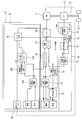
図1及び図2は、本発明の第1実施例に係る駆動力制御システムが適用された車両を示している。この駆動力制御システムは、車両駆動源としてのエンジン11と駆動輪12との間に自動変速機13が介装され、この自動変速機13と駆動輪12とは車軸14を介して連結されている。エンジン11は、ガソリンや軽油等の燃料を燃焼することにより駆動力を発生する内燃機関である。なお、エンジン11としては、モータや燃料電池等を単独もしくは組み合わせて用いても良い。自動変速機13は、この実施例では無段階・連続的に変速が可能なベルト式無段変速機である。このベルト式無段変速機は、周知の構造であるので簡単に説明すると、多数のスチールのコマと2本のスチールリングとを備えたスチールベルトが、エンジン11側に接続されるプライマリプーリと駆動輪側に接続されるセカンダリプーリとに架け渡され、ベルトの接触半径を変化させることで、変速比を無段階に変化させるものである。
駆動力制御システムは、エンジンコントロールモジュール21(ECM),変速機コントロールユニット22(CVT-CU)等の複数のコントローラを例えばCAN通信等の双方向通信可能なシステムにより接続し、必要な情報を共有可能としたものである。エンジンコントロールモジュール21は、主としてエンジン11の制御を行なうものであり、変速機コントロールユニット22は、主として自動変速機13の制御を行なう。
この駆動力制御システムでは、エンジン11及び自動変速機13を含めたパワートレインの制御として、先ず運転者の出力要求に対応するアクセルペダルのアクセル開度と車速とに基づいて、駆動輪12に伝達される最終的な駆動力の目標値である目標駆動力tFdを算出・演算し、この目標駆動力tFdに基づいて、エンジン11と自動変速機13とを制御する、いわゆるパワートレーントルクデマンド制御(PTD制御)を行なう。つまり、目標駆動力tFdに基づいて、エンジン11が出力する出力トルクの目標値である目標エンジントルクtTeと、自動変速機13の変速比の目標値である目標変速比tRtoと、を求め、目標エンジントルクtTeへ向けてエンジン11が制御されるとともに、目標変速比tRtoへ向けて自動変速機13が制御される。アクセル開度は、例えばアクセルペダルの開度を検出するアクセル開度センサの信号が用いられる。車速は、車速センサにより検出される。あるいは自動変速機の入力回転数(エンジン回転数)と変速比とを用いて車速を推定しても良い。
次に、図1を参照してエンジンコントロールモジュール21で行なわれる制御について説明すると、目標駆動力演算部23では、アクセル開度と車速に基づいて目標駆動力tFdを演算する。目標入力回転数演算部24では、目標駆動力tFdに基づいて、自動変速機13の入力回転数(つまり、エンジン回転数)の目標値である目標入力回転数tNiを演算する。
補正項演算部25では、補機類の駆動等の他の性能要求を実現するための補正項を求める。
トルクリミット部26では、目標駆動力演算部23Aで求められた目標駆動力tFdと、後述する副目標駆動力算出部24Aで求められた目標駆動力tFd’との差(tFd-tFd’)が所定値以下となるように、エンジントルクの上限を規制する。つまり、補正項演算部25による補正によって目標駆動力tFdが本来の値(tFd’)から過度に差が生じることのないように制限することで、補正項演算部25による補正による誤診断の発生を未然に防止している。
目標エンジントルク演算部27では、上記トルクリミット部26による制限の範囲内で、目標入力回転数tNi(エンジン回転数)に基づいて目標エンジントルクtTeを演算し、これをエンジン制御部28へ出力する。つまり、エンジン回転数が目標入力回転数tNiとなるように目標エンジントルクtTeを演算する。
エンジン制御部28では、目標エンジントルクtTeに基づいてスロットル開度(ガソリンエンジンの場合)、あるいは燃料噴射量(ディーゼルエンジンの場合)等を制御する。
次に、変速機コントロールユニット22により行なわれる制御について説明すると、目標変速比演算部31では、目標入力回転数tNiと車速から自動変速機13の変速比の目標値に対応する目標変速比tRtoを演算する。変速制御部32では、目標変速比tRtoに基づいて自動変速機13の変速制御を行なう。変速速度制御部33では、変速制御部32による変速の速度制御を行なう。
また、自動変速機(CVT)13の入力側および出力側には軸回転数を検出する回転センサーが備えられており、CVT診断部34では、例えば、目標変速比tRtoに対し、検出した入力側および出力側の軸回転数から計算される実変速比を比較して、その差が所定範囲内である場合には自動変速機13が正常に動作していると判断する。なお、それ以外の診断も含めて正常に動作しているか否かを判断しても構わない。
次に、エンジンコントロールモジュール21に設けられた異常判定部35の制御内容について説明する。本実施例では、一時的な変速動作の応答遅れに起因する誤診断を抑制するように、CVT診断部34により自動変速機13が正常に動作していると判断されている場合であっても、目標エンジントルクtTeと実エンジントルクrTeとに基づいて、エンジン11に起因する駆動力制御システムの異常の判定を行なうようにしている。
具体的には、副目標駆動力演算部23Aでは、上記の目標駆動力演算部23と同様に、アクセル開度と車速に基づいて目標駆動力tFd’を演算する。なお、この実施例では、副目標駆動力演算部23Aを設け、異常診断に用いる目標駆動力tFd’を別個に求めているが、副目標駆動力演算部23Aを省略し、上記の目標駆動力tFdをそのまま異常診断に用いるようにしても良い。
副目標入力回転数演算部24Aでは、上記の目標入力回転数演算部24と同様、目標駆動力tFd’等に基づいて、自動変速機13の入力回転数(つまり、エンジン回転数)の目標値である目標入力回転数tNi’を演算する。なお、副目標入力回転数演算部24Aを省略し、上記の目標入力回転数演算部24により求められる目標入力回転数tNiを異常診断に用いるようにしても良い。
副目標エンジントルク演算部27A(目標エンジントルク算出部)では、目標駆動力tFd’と目標入力回転数tNi’等に基づいて、目標エンジントルクtTe’を演算する。なお、副目標エンジントルク演算部27Aを省略し、上記の目標エンジントルク演算部27で求められた目標エンジントルクtTeを異常診断に用いるようにしても良い。
実エンジントルク検出部36では、エンジン11の出力トルクである実エンジントルクrTe’を検出する。この実エンジントルクrTe’は、例えばエアフロメータにより検出される吸入空気量の他、点火時期,EGR率及び燃料噴射時期を勘案して求められる。
トルク比較部38では、実エンジントルクrTe’と目標エンジントルクtTe’とを比較し、両者の間に所定のしきい値sTeを超える差が発生しているときに、エンジン11に起因する駆動力制御システムの異常であると判定する。具体的には、目標エンジントルクtTe’に、予め設定された所定の診断用のしきい値sTeを加算し、この加算値(tTe’+sTe)を実エンジントルクrTe’と比較する。そして、実エンジントルクrTe’が上記の加算値(tTe’+sTe)を超えていれば異常と判定する。例えば、スロットル故障や演算値異常等が発生した場合に、異常と判定される。異常と判定された場合には、該当する異常診断コード(DTC)を記憶する。このように記憶された異常診断コードに応じて、フェールセーフ運転モードが実施され、あるいは表示や音声により搭乗者に異常を報知する。
上記のしきい値sTeは、例えばスロットル故障や演算値異常等のエンジンに起因する駆動力制御システムの異常が発生した際に、目標エンジントルクtTe’と実エンジントルクrTe’との間に生じる差を考慮して、実験やシュミレーションによって予め設定される値である。図2に示すように、正常な車両運転状態においても実エンジントルクrTe’は目標エンジントルクtTe’に対して微小に変動するものの、このような微小な変動で誤って異常と診断されることのないように、上記のしきい値sTeは、ある程度の大きさを確保したMIN値と、駆動力制御システムの異常が発生して車両要求よりも大きな駆動トルクが発生した際に運転者がフェールセーフとしてブレーキ等で余裕を持って対応できる程度の小ささ(例えば加速度で0.2G)を確保したMAX値と、の間で設定すればよい。また、スロットル故障や演算値異常等のエンジンに起因する駆動力制御システムの異常である場合には確実に異常と診断されるように、このようなエンジンに起因する駆動力制御システムの異常である場合に生じる目標エンジントルクtTe’と実エンジントルクrTe’との差(絶対値)よりも小さな値として設定される。
なお、この実施例では、実エンジントルクrTe’が目標エンジントルクtTe’に対して過剰に大きくなる形態の異常を判定するために、目標エンジントルクtTe’に対してしきい値sTe(絶対値)を加算し、この加算値(tTe’+sTe)を実エンジントルクrTe’が超えている場合に異常と判定しているが、実エンジントルクrTe’が目標エンジントルクtTe’に対して過剰に小さくなる形態の異常を判定することも可能である。この場合、目標エンジントルクtTe’に対してしきい値sTe(正の値)を減算し、この減算値(tTe’-sTe)を実エンジントルクrTe’が下回っている場合に、異常と判定する。また、両者を組み合わせて、実エンジントルクrTe’が目標エンジントルクtTe’に対して過剰に大きくなる形態と過剰に小さくなる形態の双方の異常を判定するようにしても良い。
ここで、上記のトルク比較部38においては、極低温状態でのエンジントルクのばらつきにより誤って異常診断が行なわれることのないように、エンジンの吸気温度を検出もしくは推定し、この吸気温度に基づいて異常診断判定処理の補正を行なう。具体的には、吸気温度が極めて低い極低温時には、駆動力制御システムが正常であるにもかかわらず誤って異常と誤判定されることを抑制するために、診断用のしきい値sTeが大きくなる方向に補正を行なう。つまり、目標エンジントルクtTe’又はしきい値sTeを増加側に補正するか、あるいは実エンジントルクrTe’を低下側に補正する。
図3及び図4は、比較例に係る駆動力制御システムの異常診断装置を示している。なお、上記第1実施例と同じ構成要素には同じ参照符号を付し、重複する説明を適宜省略する。
この比較例では、実変速比rRto’を検出あるいは推定し、実駆動力演算部41において、実エンジントルクrTe’と実変速比rRto’とに基づいて、実駆動力rFd’を求めている。そして、駆動力診断部42において、実駆動力rFd’と、目標駆動力tFd’と、の比較に基づいて異常診断を行なう構成となっている。具体的には、図4に示すように、目標駆動力tFdと予め設定した診断用のしきい値sFdとを加算した値(tFd’+sFd)と、実駆動力rFd’とを比較し、実駆動力rFd’が加算した値(tFd’+sFd)を超えた場合に、異常と診断している。
次に、図2及び図4を参照して、本実施例と比較例との動作の相違を、アクセル開度が増加する車両加速時を例にとって説明する。
運転者によるアクセルペダルの踏み込み操作によりアクセル開度が上昇する加速時には、車速が上昇するとともに変速比が低下する。この際、例えば低温時に自動変速機13のプライマリ側へ供給する油圧の立ち上がりが遅れることなどにより、自動変速機13自体は正常でありながら、過渡的に実変速比rRto’が目標変速比tRto’から乖離することがある。
ここで、図4に示す比較例においては、目標駆動力tFd’の算出に目標変速比tRto’が用いられるとともに、実駆動力rFd’の算出に実変速比rRto’が用いられているために、実変速比rRto’と目標変速比tRto’との乖離の影響によって、エンジン11及び自動変速機13を含めた駆動力制御システムが正常に動作しているにもかかわらず、実駆動力rFd’が加算値(tFd’+sFd)を超えてしまい、異常と誤診断されるおそれがある。
これに対し、図2に示す本実施例では、目標駆動力を用いたパワートレーントルクデマンド制御(PTD制御)を採用した車両でありながら、異常診断に駆動力ではなくエンジントルクを用い、具体的には目標エンジントルクtTe’と実エンジントルクrTe’との比較に基づいて異常を診断しており、これらの目標エンジントルクtTe’と実エンジントルクrTe’の算出には実変速比rRto’が用いられていないため、変速比の悪影響を排除した形で診断を行なうことができる。従って、自動変速機13は正常でありながら過渡的に実変速比rRto’が目標変速比tRto’から乖離するような状況においても、誤って異常であると誤判定する事態を抑制もしくは回避することができ、診断精度を向上することができる。
図5は、本実施例の異常診断の制御の流れを示すフローチャートであり、このルーチンは極短期間(例えば10ms)毎に繰り返し実行される。
ステップS11では、自動変速機13が正常であるかをCVT診断部34にて判定する。この判定は、自動変速機13の入力側および出力側には軸回転数を検出する回転センサーが備えられており、目標変速比tRtoに対し、検出した入力側および出力側の軸回転数から計算される実変速比を比較して、その差が所定範囲内である場合には自動変速機13が正常に動作していると判断する。なお、それ以外の診断も含めて正常に動作しているか否かを判断しても構わない。また、自動変速機の異常判定の判定結果はフラグとして出力される。自動変速機13が正常でない場合、ステップS12へ進み、対応するエラーコードを出力して本ルーチンを終了する。ステップS13では、上記の副エンジントルク演算部27Aにより目標エンジントルクtTe’を算出する。ステップS14では、実エンジントルク検出部36により実エンジントルクrTe’を検出する。ステップS15では、上記のトルク比較部38により、目標エンジントルクtTeと実エンジントルクrTe’との間に所定のしきい値sTeを超える差が発生しているかを判定する。差が発生していれば、異常と判定してステップS16へ進み、対応するエラーコードを出力して本ルーチンを終了する。
このように本実施例では、自動変速機13が正常な場合に、エンジントルクに基づいて駆動力制御システムの異常を判定しているために、正常な自動変速機13における変速動作の一時的な応答遅れに伴って異常と診断されてしまうことを確実に抑制することができる。
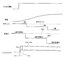
次に、図6を参照して本発明の第2実施例を説明する。なお、図中の下側3段のギアレンジ,変速比及びエンジントルクにおいて、実線は目標値(もしくは加算値)を、破線は推定値(実ギアレンジ,実変速比,実エンジントルク)を表している。
上記の第1実施例では、自動変速機13としてベルト式の無段変速機を用いているが、この第2実施例では、自動変速機13として、有段式の自動変速機を用いている。このように有段式の自動変速機を用いた場合であっても、無段変速機を用いた上記第1実施例と同様に、車両加速時に、自動変速機13自体は正常でありながら過渡的に実変速比rRto’が目標変速比tRto’から大きく乖離することがある。例えば、目標駆動力tFdを実現するために、エンジンコントロールモジュール21から変速機コントロールユニット22へ目標ギアレンジを送信する制御の場合、故障を除いても目標ギアレンジ通りに実ギアレンジが動かない場合がある。例えば、変速機コントロールユニット22がユニット保護のためにエンジンコントロールモジュール21からの要求を一時的に無視する場合や、自動変速機が変速を行なうために十分な油圧が確保されていない場合等である。
このような場合に、実変速比rRto’から実駆動力rFd’を演算して推定する場合、図6に示すように、目標変速比tRto’に対する実変速比rRto’の乖離分の影響により、有段式の自動変速機が正常であるにもかかわらず、異常と誤診断されるおそれがある。
本実施例では、上記第1実施例と同様、エンジントルクに基づいて異常診断を行なっており、変速比の影響を排除しているために、仮に目標変速比tRto’に対して実変速比rRto’が一時的に乖離したとしても、実エンジントルクrTe’が加算値(tTe’+sTe)から大きく外れることがなく、異常と誤判定する事態を抑制もしくは回避することで、診断精度を向上することができる。
以上のように本発明を具体的な実施例に基づいて説明してきたが、本発明は上記実施例に限定されるものではなく、種々の変形・変更を含むものである。例えば、上記実施例では、加速度が目標よりも大きくなる形態の異常に本発明を適用しているが、同様にして、減速度が目標よりも小さくなる形態の異常に本発明を適用することも可能である。
Claims (5)
- エンジンと駆動輪との間に自動変速機が介装され、
運転者出力要求に基づいて、上記駆動輪に伝達される目標駆動力を算出し、この目標駆動力に基づいて、上記自動変速機及び上記エンジンを制御する駆動力制御システムの異常診断方法であって、
上記目標駆動力に基づいて目標エンジントルクを算出し、
上記エンジンの実エンジントルクを検出し、
上記自動変速機が正常であると判断されている場合に、上記目標エンジントルクと上記実エンジントルクとの間に所定のしきい値を超える差が発生すると、上記エンジンに起因する駆動力制御システムの異常であると判定する駆動力制御システムの異常診断方法。 - 上記エンジンの吸気温度を検出し、
この吸気温度が低い極低温時には、上記しきい値が大きくなるように補正を行なう請求項1に記載の駆動力制御システムの異常診断方法。 - 実エンジントルクは、吸入空気量の検出値に基づいて求められる請求項1又は2に記載の駆動力制御システムの異常診断方法。
- 上記自動変速機が正常であると判断されている場合に、上記実エンジントルクが、上記目標エンジントルクに上記しきい値を加算した加算値を超えている場合に、上記エンジンに起因する駆動力制御システムの異常であると判定する請求項1~3のいずれかに記載の駆動力制御システムの異常診断方法。
- エンジンと駆動輪との間に自動変速機が介装され、
運転者出力要求に基づいて、上記駆動輪に伝達される目標駆動力を算出し、この目標駆動力に基づいて、上記自動変速機及び上記エンジンを制御する駆動力制御システムの異常診断装置であって、
上記目標駆動力に基づいて、上記エンジンの目標エンジントルクを算出する目標エンジントルク算出部と、
上記エンジンの実エンジントルクを検出し、上記目標エンジントルクと上記実エンジントルクとの間に所定のしきい値を超える差が発生すると、上記エンジンに起因する駆動力制御システムの異常であると判定する異常判定部と、を有する駆動力制御システムの異常診断装置。
Priority Applications (5)
| Application Number | Priority Date | Filing Date | Title |
|---|---|---|---|
| US16/302,123 US10867456B2 (en) | 2016-05-27 | 2016-05-27 | Abnormality diagnostic method and abnormality diagnostic device for driving force control system |
| PCT/JP2016/065675 WO2017203678A1 (ja) | 2016-05-27 | 2016-05-27 | 駆動力制御システムの異常診断方法及び異常診断装置 |
| JP2018518904A JP6525106B2 (ja) | 2016-05-27 | 2016-05-27 | 駆動力制御システムの異常診断方法及び異常診断装置 |
| CN201680086121.XA CN109196208B (zh) | 2016-05-27 | 2016-05-27 | 驱动力控制系统的异常诊断方法以及异常诊断装置 |
| EP16903159.8A EP3467286A4 (en) | 2016-05-27 | 2016-05-27 | ANOMALY DIAGNOSTIC METHOD AND ANOMALY DIAGNOSIS DEVICE FOR A TRAINING FORCE CONTROL SYSTEM |
Applications Claiming Priority (1)
| Application Number | Priority Date | Filing Date | Title |
|---|---|---|---|
| PCT/JP2016/065675 WO2017203678A1 (ja) | 2016-05-27 | 2016-05-27 | 駆動力制御システムの異常診断方法及び異常診断装置 |
Publications (1)
| Publication Number | Publication Date |
|---|---|
| WO2017203678A1 true WO2017203678A1 (ja) | 2017-11-30 |
Family
ID=60412188
Family Applications (1)
| Application Number | Title | Priority Date | Filing Date |
|---|---|---|---|
| PCT/JP2016/065675 WO2017203678A1 (ja) | 2016-05-27 | 2016-05-27 | 駆動力制御システムの異常診断方法及び異常診断装置 |
Country Status (5)
| Country | Link |
|---|---|
| US (1) | US10867456B2 (ja) |
| EP (1) | EP3467286A4 (ja) |
| JP (1) | JP6525106B2 (ja) |
| CN (1) | CN109196208B (ja) |
| WO (1) | WO2017203678A1 (ja) |
Families Citing this family (7)
| Publication number | Priority date | Publication date | Assignee | Title |
|---|---|---|---|---|
| US10894547B2 (en) * | 2018-11-16 | 2021-01-19 | Here Global B.V. | Method, apparatus, and system for assessing safety and comfort systems of a vehicle |
| CN109506955B (zh) * | 2018-12-25 | 2021-10-15 | 重庆工商大学 | 一种扭矩限制因素的获取方法、装置及系统 |
| US11434846B2 (en) * | 2019-09-11 | 2022-09-06 | Denso Corporation | Engine control device |
| CN112590564B (zh) * | 2021-01-04 | 2022-08-05 | 潍柴动力股份有限公司 | 电机扭矩的控制方法、装置、电子设备以及存储介质 |
| JP7348219B2 (ja) * | 2021-02-18 | 2023-09-20 | 本田技研工業株式会社 | 制御装置、および車両 |
| CN113246977B (zh) * | 2021-07-08 | 2021-10-01 | 中汽研(天津)汽车工程研究院有限公司 | 一种基于功能安全的adas纵向控制扭矩监控装置及方法 |
| CN114165344A (zh) * | 2021-12-09 | 2022-03-11 | 安徽江淮汽车集团股份有限公司 | 混动车型gpf主动再生控制方法 |
Citations (3)
| Publication number | Priority date | Publication date | Assignee | Title |
|---|---|---|---|---|
| JP2010043536A (ja) * | 2008-08-08 | 2010-02-25 | Denso Corp | 車両の制御装置 |
| JP2010175063A (ja) * | 2009-02-02 | 2010-08-12 | Toyota Motor Corp | 変速制御装置および変速制御方法 |
| JP2010236416A (ja) | 2009-03-31 | 2010-10-21 | Toyota Motor Corp | 車両の異常判定装置 |
Family Cites Families (16)
| Publication number | Priority date | Publication date | Assignee | Title |
|---|---|---|---|---|
| JP3678777B2 (ja) * | 1994-10-31 | 2005-08-03 | 富士重工業株式会社 | 無段変速機の制御装置 |
| DE19739565B4 (de) * | 1997-09-10 | 2007-09-13 | Robert Bosch Gmbh | Verfahren und Vorrichtung zur Steuerung des Drehmoments einer Antriebseinheit eines Kraftfahrzeugs |
| JP3573066B2 (ja) * | 2000-06-07 | 2004-10-06 | 日産自動車株式会社 | 車両の駆動力制御装置 |
| JP4457981B2 (ja) * | 2005-05-26 | 2010-04-28 | トヨタ自動車株式会社 | 車両用駆動装置の制御装置 |
| JP4238847B2 (ja) * | 2005-05-30 | 2009-03-18 | トヨタ自動車株式会社 | 車両用駆動装置の制御装置 |
| JP4770309B2 (ja) * | 2005-07-19 | 2011-09-14 | 日産自動車株式会社 | 車両のエンジン出力制御装置 |
| JP4923772B2 (ja) * | 2005-07-26 | 2012-04-25 | 日産自動車株式会社 | エンジンの過回転防止装置 |
| JP2009255776A (ja) * | 2008-04-17 | 2009-11-05 | Aisin Ai Co Ltd | ハイブリッド動力装置 |
| MX2012007871A (es) * | 2010-03-16 | 2012-07-25 | Nissan Motor | Vehiculo hibrido. |
| JP2011240816A (ja) * | 2010-05-18 | 2011-12-01 | Denso Corp | 自律走行制御装置 |
| US8636620B2 (en) * | 2010-10-28 | 2014-01-28 | Jatco Ltd | Automatic transmission |
| DE102011080859A1 (de) * | 2011-08-11 | 2013-02-14 | Robert Bosch Gmbh | Verfahren und Vorrichtung zur Überwachung eines Steuergeräts zum Betreiben eines Motorsystems |
| JP2013151246A (ja) * | 2012-01-26 | 2013-08-08 | Nissan Motor Co Ltd | 不可逆回転伝動系のロックオフ制御装置 |
| WO2013187464A1 (ja) * | 2012-06-13 | 2013-12-19 | 日産自動車株式会社 | 車両の駆動力制御装置 |
| CN105121822B (zh) * | 2013-11-13 | 2017-10-13 | 本田技研工业株式会社 | 原动机的驱动控制装置 |
| JP5873116B2 (ja) * | 2014-01-23 | 2016-03-01 | 富士重工業株式会社 | 無段変速機の異常検知装置、及び、無段変速機の異常検知方法 |
-
2016
- 2016-05-27 CN CN201680086121.XA patent/CN109196208B/zh active Active
- 2016-05-27 EP EP16903159.8A patent/EP3467286A4/en active Pending
- 2016-05-27 US US16/302,123 patent/US10867456B2/en active Active
- 2016-05-27 WO PCT/JP2016/065675 patent/WO2017203678A1/ja active Application Filing
- 2016-05-27 JP JP2018518904A patent/JP6525106B2/ja active Active
Patent Citations (3)
| Publication number | Priority date | Publication date | Assignee | Title |
|---|---|---|---|---|
| JP2010043536A (ja) * | 2008-08-08 | 2010-02-25 | Denso Corp | 車両の制御装置 |
| JP2010175063A (ja) * | 2009-02-02 | 2010-08-12 | Toyota Motor Corp | 変速制御装置および変速制御方法 |
| JP2010236416A (ja) | 2009-03-31 | 2010-10-21 | Toyota Motor Corp | 車両の異常判定装置 |
Non-Patent Citations (1)
| Title |
|---|
| See also references of EP3467286A4 |
Also Published As
| Publication number | Publication date |
|---|---|
| CN109196208B (zh) | 2021-08-13 |
| EP3467286A4 (en) | 2019-05-22 |
| JP6525106B2 (ja) | 2019-06-05 |
| CN109196208A (zh) | 2019-01-11 |
| JPWO2017203678A1 (ja) | 2018-12-06 |
| US10867456B2 (en) | 2020-12-15 |
| EP3467286A1 (en) | 2019-04-10 |
| US20190188927A1 (en) | 2019-06-20 |
Similar Documents
| Publication | Publication Date | Title |
|---|---|---|
| WO2017203678A1 (ja) | 駆動力制御システムの異常診断方法及び異常診断装置 | |
| US9863334B2 (en) | Drive control apparatus for prime mover | |
| EP1403570B1 (en) | Transmission controller of v-belt type continuously variable automatic transmission | |
| JP2008239130A (ja) | 車両の制御装置 | |
| EP2899084B1 (en) | Vehicle control device and method for controlling vehicle | |
| US9334953B2 (en) | Control apparatus for vehicle power transmission mechanism | |
| US9671015B2 (en) | Abnormality detection device for continuously variable transmission and method of detecting abnormality of the continuously variable transmission | |
| JP5783055B2 (ja) | 変速機の異常判定装置 | |
| US8838350B2 (en) | Automatic transmission control device | |
| JP4720870B2 (ja) | 機関用燃料診断装置及び同装置を備える自動変速機の制御装置 | |
| EP2868904B1 (en) | Control device for internal combustion engine | |
| KR100974602B1 (ko) | 댐퍼 클러치 제어장치 및 방법 | |
| JP2013152008A (ja) | ベルト式無段変速機の制御装置 | |
| JP7188334B2 (ja) | 変速比制御装置 | |
| KR20080062236A (ko) | 자동 변속 차량의 라인압 제어 장치 및 방법 | |
| KR101606362B1 (ko) | 변속 제어 장치 및 변속 제어 방법 | |
| JP5195534B2 (ja) | 動力伝達装置 | |
| JP2017053238A (ja) | 車両用制御装置 | |
| JP2005264773A (ja) | 内燃機関の制御装置 | |
| JP2024025891A (ja) | 車両の制御装置 | |
| JP5082883B2 (ja) | パワートレーンの制御装置 | |
| JP2013047538A (ja) | 車両の動力伝達制御装置 | |
| JP2005226815A (ja) | 無段変速機の制御装置 | |
| JP2007023934A (ja) | エンジン出力制御装置 | |
| JP2006170069A (ja) | エンジンの制御装置 |
Legal Events
| Date | Code | Title | Description |
|---|---|---|---|
| WWE | Wipo information: entry into national phase |
Ref document number: 2018518904 Country of ref document: JP |
|
| 121 | Ep: the epo has been informed by wipo that ep was designated in this application |
Ref document number: 16903159 Country of ref document: EP Kind code of ref document: A1 |
|
| NENP | Non-entry into the national phase |
Ref country code: DE |
|
| ENP | Entry into the national phase |
Ref document number: 2016903159 Country of ref document: EP Effective date: 20190102 |