WO2017200067A1 - バルブ及び蒸気タービン設備 - Google Patents
バルブ及び蒸気タービン設備 Download PDFInfo
- Publication number
- WO2017200067A1 WO2017200067A1 PCT/JP2017/018760 JP2017018760W WO2017200067A1 WO 2017200067 A1 WO2017200067 A1 WO 2017200067A1 JP 2017018760 W JP2017018760 W JP 2017018760W WO 2017200067 A1 WO2017200067 A1 WO 2017200067A1
- Authority
- WO
- WIPO (PCT)
- Prior art keywords
- valve
- valve body
- stem
- seat
- valve stem
- Prior art date
- Legal status (The legal status is an assumption and is not a legal conclusion. Google has not performed a legal analysis and makes no representation as to the accuracy of the status listed.)
- Ceased
Links
Images

Classifications
-
- F—MECHANICAL ENGINEERING; LIGHTING; HEATING; WEAPONS; BLASTING
- F16—ENGINEERING ELEMENTS AND UNITS; GENERAL MEASURES FOR PRODUCING AND MAINTAINING EFFECTIVE FUNCTIONING OF MACHINES OR INSTALLATIONS; THERMAL INSULATION IN GENERAL
- F16K—VALVES; TAPS; COCKS; ACTUATING-FLOATS; DEVICES FOR VENTING OR AERATING
- F16K15/00—Check valves
- F16K15/02—Check valves with guided rigid valve members
- F16K15/06—Check valves with guided rigid valve members with guided stems
- F16K15/063—Check valves with guided rigid valve members with guided stems the valve being loaded by a spring
-
- F—MECHANICAL ENGINEERING; LIGHTING; HEATING; WEAPONS; BLASTING
- F01—MACHINES OR ENGINES IN GENERAL; ENGINE PLANTS IN GENERAL; STEAM ENGINES
- F01D—NON-POSITIVE DISPLACEMENT MACHINES OR ENGINES, e.g. STEAM TURBINES
- F01D17/00—Regulating or controlling by varying flow
- F01D17/10—Final actuators
- F01D17/12—Final actuators arranged in stator parts
- F01D17/14—Final actuators arranged in stator parts varying effective cross-sectional area of nozzles or guide conduits
- F01D17/141—Final actuators arranged in stator parts varying effective cross-sectional area of nozzles or guide conduits by means of shiftable members or valves obturating part of the flow path
- F01D17/145—Final actuators arranged in stator parts varying effective cross-sectional area of nozzles or guide conduits by means of shiftable members or valves obturating part of the flow path by means of valves, e.g. for steam turbines
-
- F—MECHANICAL ENGINEERING; LIGHTING; HEATING; WEAPONS; BLASTING
- F01—MACHINES OR ENGINES IN GENERAL; ENGINE PLANTS IN GENERAL; STEAM ENGINES
- F01D—NON-POSITIVE DISPLACEMENT MACHINES OR ENGINES, e.g. STEAM TURBINES
- F01D17/00—Regulating or controlling by varying flow
- F01D17/10—Final actuators
-
- F—MECHANICAL ENGINEERING; LIGHTING; HEATING; WEAPONS; BLASTING
- F01—MACHINES OR ENGINES IN GENERAL; ENGINE PLANTS IN GENERAL; STEAM ENGINES
- F01D—NON-POSITIVE DISPLACEMENT MACHINES OR ENGINES, e.g. STEAM TURBINES
- F01D25/00—Component parts, details, or accessories, not provided for in, or of interest apart from, other groups
-
- F—MECHANICAL ENGINEERING; LIGHTING; HEATING; WEAPONS; BLASTING
- F16—ENGINEERING ELEMENTS AND UNITS; GENERAL MEASURES FOR PRODUCING AND MAINTAINING EFFECTIVE FUNCTIONING OF MACHINES OR INSTALLATIONS; THERMAL INSULATION IN GENERAL
- F16K—VALVES; TAPS; COCKS; ACTUATING-FLOATS; DEVICES FOR VENTING OR AERATING
- F16K1/00—Lift valves or globe valves, i.e. cut-off apparatus with closure members having at least a component of their opening and closing motion perpendicular to the closing faces
- F16K1/32—Details
-
- F—MECHANICAL ENGINEERING; LIGHTING; HEATING; WEAPONS; BLASTING
- F16—ENGINEERING ELEMENTS AND UNITS; GENERAL MEASURES FOR PRODUCING AND MAINTAINING EFFECTIVE FUNCTIONING OF MACHINES OR INSTALLATIONS; THERMAL INSULATION IN GENERAL
- F16K—VALVES; TAPS; COCKS; ACTUATING-FLOATS; DEVICES FOR VENTING OR AERATING
- F16K1/00—Lift valves or globe valves, i.e. cut-off apparatus with closure members having at least a component of their opening and closing motion perpendicular to the closing faces
- F16K1/32—Details
- F16K1/34—Cutting-off parts, e.g. valve members, seats
-
- F—MECHANICAL ENGINEERING; LIGHTING; HEATING; WEAPONS; BLASTING
- F16—ENGINEERING ELEMENTS AND UNITS; GENERAL MEASURES FOR PRODUCING AND MAINTAINING EFFECTIVE FUNCTIONING OF MACHINES OR INSTALLATIONS; THERMAL INSULATION IN GENERAL
- F16K—VALVES; TAPS; COCKS; ACTUATING-FLOATS; DEVICES FOR VENTING OR AERATING
- F16K1/00—Lift valves or globe valves, i.e. cut-off apparatus with closure members having at least a component of their opening and closing motion perpendicular to the closing faces
- F16K1/32—Details
- F16K1/34—Cutting-off parts, e.g. valve members, seats
- F16K1/44—Details of seats or valve members of double-seat valves
-
- F—MECHANICAL ENGINEERING; LIGHTING; HEATING; WEAPONS; BLASTING
- F16—ENGINEERING ELEMENTS AND UNITS; GENERAL MEASURES FOR PRODUCING AND MAINTAINING EFFECTIVE FUNCTIONING OF MACHINES OR INSTALLATIONS; THERMAL INSULATION IN GENERAL
- F16K—VALVES; TAPS; COCKS; ACTUATING-FLOATS; DEVICES FOR VENTING OR AERATING
- F16K1/00—Lift valves or globe valves, i.e. cut-off apparatus with closure members having at least a component of their opening and closing motion perpendicular to the closing faces
- F16K1/32—Details
- F16K1/34—Cutting-off parts, e.g. valve members, seats
- F16K1/36—Valve members
- F16K1/38—Valve members of conical shape
-
- F—MECHANICAL ENGINEERING; LIGHTING; HEATING; WEAPONS; BLASTING
- F16—ENGINEERING ELEMENTS AND UNITS; GENERAL MEASURES FOR PRODUCING AND MAINTAINING EFFECTIVE FUNCTIONING OF MACHINES OR INSTALLATIONS; THERMAL INSULATION IN GENERAL
- F16K—VALVES; TAPS; COCKS; ACTUATING-FLOATS; DEVICES FOR VENTING OR AERATING
- F16K1/00—Lift valves or globe valves, i.e. cut-off apparatus with closure members having at least a component of their opening and closing motion perpendicular to the closing faces
- F16K1/32—Details
- F16K1/34—Cutting-off parts, e.g. valve members, seats
- F16K1/44—Details of seats or valve members of double-seat valves
- F16K1/443—Details of seats or valve members of double-seat valves the seats being in series
Definitions
- the present disclosure relates to a valve and a steam turbine facility including the valve.
- Patent Document 1 discloses a steam valve used for a steam turbine.
- this steam valve when the valve is closed, the seat surface of the valve body is seated on the valve seat, whereby the flow of steam is interrupted, and the valve rod to which the valve body is connected, and the bonnet through which the valve rod is inserted,
- the back seat provided in the enlarged diameter portion of the valve stem comes into contact with the bonnet.
- Patent Document 1 in order to interrupt
- At least one embodiment of the present invention aims to provide a valve and a steam turbine facility capable of reducing fluid leakage.
- a valve includes: A valve stem, A first valve body provided on the tip side of the valve stem and configured to be driven via the valve stem; A first valve seat on which the first valve body can be seated; A sub-seat surface along a direction intersecting the axial direction of the valve stem; A sub seat portion provided on the base end side of the valve stem with respect to the first valve body, and configured to abut on the sub seat surface when the first valve body is closed; A biasing member capable of generating a biasing force along the axial direction of the valve stem, One of the first valve body or the sub seat portion is relatively displaceable in the axial direction with respect to the valve stem, and is directed toward one of the first valve seat or the sub seat surface by the biasing member. Be energized.
- one of the first valve body or the sub seat portion can be displaced relative to the valve stem in the axial direction of the valve stem, and the first valve seat or the sub seat surface can be moved by the biasing member. It is energized towards one side. Accordingly, when the first valve body is closed, the other of the first valve body or the sub seat portion is seated or abutted on the other of the first valve seat or the sub seat surface, and the first valve body or the sub seat portion is One is pressed against the one of the first valve seat and the sub-seat surface by the urging member, so that both the first valve body and the sub-seat portion can be reliably sealed. Thus, fluid leakage in the valve can be reduced.
- the first valve body is relatively displaceable in the axial direction with respect to the valve stem, and the first valve seat is mounted on the first valve seat by the biasing member provided between the first valve body and the valve stem. It is energized towards.
- the first valve body can be displaced relative to the valve stem in the axial direction of the valve stem, and is biased toward the first valve seat by the biasing member.
- the sub seat portion comes into contact with the sub seat surface, and the first valve body is pressed against the first valve seat by the urging member. Therefore, the first valve body and the sub seat portion Both can be reliably sealed. Thus, fluid leakage in the valve can be reduced.
- the valve stem has a valve stem side engaging portion including a convex portion or a concave portion protruding or recessed in the radial direction of the valve stem on the distal end side
- the first valve body has a valve body side engaging portion including a concave portion or a convex portion that is depressed or protruded in the radial direction so as to be engaged with the valve stem side engaging portion
- the valve stem side engaging portion is loosely fitted to the valve body side engaging portion so as to allow relative displacement in the axial direction of the first valve body with respect to the valve stem.
- the valve stem side engaging portion is loosely fitted to the valve body side engaging portion. That is, a gap is formed between the valve stem side engaging portion and the valve body side engaging portion in the axial direction of the valve stem. Therefore, since the relative displacement in the axial direction of the first valve body with respect to the valve stem is allowed, the first valve body can be appropriately pressed against the first valve seat by the urging force of the urging member, and the first valve body and It can be reliably sealed at both sub-sheets.
- the valve stem has the convex portion protruding outward in the radial direction as the valve stem-side engaging portion
- the convex portion as the valve stem side engaging portion is: A first surface facing the first valve body facing the axial valve opening side of the valve stem; A second surface facing the first valve body facing the axial valve closing side of the valve stem; Have A gap is provided between at least one of the first surface and the first valve body, or between the second surface and the first valve body.
- a gap is provided on at least one of the first valve body and the first surface or the second surface of the convex portion as the valve rod side engaging portion. That is, a gap is formed between the convex portion as the valve stem side engaging portion and the first valve body in the axial direction of the valve stem. Therefore, since the axial displacement of the first valve body with respect to the valve stem is allowed, the first valve body can be pressed against the first valve seat by the biasing force of the biasing member, and the first valve body and the sub-seat It can be surely sealed at both parts.
- the gap (the first valve body) is formed between the first surface facing the valve opening side of the convex portion as the valve rod side engaging portion and the first valve body. 1 gap) is formed, and a gap (second gap) is formed between the first valve body and the second surface facing the valve closing side of the convex portion as the valve rod side engaging portion.
- the first clearance is formed on the valve opening side with respect to the valve rod side engaging portion (convex portion), so that the valve accompanying the stoppage of the flow of fluid (for example, steam) to the valve
- the valve stem contracts due to the temperature drop of the rod, it is possible to prevent the first valve body from being lifted by the valve stem.
- the alignment of the first valve body can be maintained.
- the second valve gap is formed on the valve closing side with respect to the valve rod side engaging portion (convex portion), so that the first valve body and the sub seat portion cannot be seated simultaneously. Even if it is a case, the favorable seal
- valve stem has a valve stem hole extending in the axial direction so as to open on the distal end surface of the valve stem on the distal end side,
- the urging member is a spring provided inside the valve stem hole.
- an axial biasing force can be applied to the first valve body by the spring guided by the valve stem hole extending in the axial direction of the valve stem. Accordingly, the first valve body is appropriately pressed against the first valve seat by the urging member, so that both the first valve body and the sub seat portion can be reliably sealed.
- the valve in the configuration of (6) above, is It is located between the first valve body and the biasing member and transmits the biasing force to the first valve body, and engages with the valve stem hole and is guided in the axial direction by the valve stem hole.
- An urging force receiving portion configured to be further configured.
- the first valve body by applying an urging force along the axial direction to the first valve body through the urging force receiving portion configured to be guided in the axial direction by the valve stem hole, The first valve body can be appropriately pressed by the first valve seat. For this reason, it can seal reliably in both a 1st valve body and a subseat part in a valve
- the urging force receiving portion has a spherical shape at least partially on the first valve body side, and is configured to contact the first valve body at the spherical portion.
- the urging force receiving portion is in contact with the first valve body at the spherical portion, so stress concentration is reduced compared to the case where the urging force receiving portion is in contact with the first valve body at the corner portion. It is possible to improve the life of the urging force receiving portion or the first valve body.
- the urging force receiving portion has a protrusion that engages with a groove formed in the first valve body so as to be recessed in the axial direction of the valve stem.
- the center position of the urging force receiving portion is set to the center of the valve stem by the protrusion engaging with the groove formed in the first valve body so as to be recessed in the axial direction of the valve stem. It can be reliably aligned with the shaft. Thereby, the urging
- a second valve body having an inner wall surface forming the first valve seat, and housing the first valve body in an internal space defined by the inner wall surface;
- a valve casing having a second valve seat on which the second valve body can be seated; With When the second valve body is in the valve opening position away from the second valve seat, one of the valve rod or the first valve body is in the valve opening direction of the first valve body with respect to the second valve body. Configured to be energized.
- the second valve body and the first valve body are seated in stages, so the second valve body and the first valve body are seated integrally.
- the mass of the valve body that collides with the valve seat is reduced compared to (for example, when the second valve body is seated on the second valve seat while the first valve body is seated on the second valve body).
- the second valve body in the configuration of (10), includes a first bush located on the outer peripheral side of the valve stem, for guiding the valve stem in the axial direction of the valve stem, When the second valve body is in the valve open position, a first chamber formed between the first bush and the valve rod is provided in the second valve body in which the first valve body is accommodated. It is comprised so that it may become a low pressure rather than the pressure of internal space.
- the first chamber formed between the first bush and the valve rod via the communication path is The pressure is lower than the pressure in the internal space of the two-valve body. Therefore, the urging force in the valve opening direction of the child valve based on the pressure difference between the first chamber and the internal space of the second valve element acts on the valve stem. Therefore, according to the configuration of (11), when the valve is closed, the second valve body and the first valve body are seated in stages due to the biasing force based on the pressure difference described above. The mass of the valve body that collides with the valve seat is reduced as compared with the case where the single valve body is integrally seated. Thereby, since the impact force which arises in a valve body and a valve seat by the collision of a valve body and a valve seat is reduced, damage to a seat part can be reduced.
- the first chamber is a lift gap for lifting the valve stem and the first valve body relative to the second valve body.
- a chamber can be formed.
- the valve stem has a communication passage extending in the axial direction inside the valve stem, When the second valve body is in the valve open position, the first chamber communicates with the second chamber having a lower pressure than the first chamber via the communication passage. When the second valve body is in the valve closing position, the first chamber and the second chamber are configured not to communicate with each other.
- the pressure in the first chamber is reduced by communicating the first chamber with the second chamber via the communication path.
- the biasing force in the valve opening direction of the first valve body based on the pressure difference between the first chamber and the internal space of the second valve body can be created.
- the first chamber and the second chamber do not communicate with each other, so that the fluid traveling from the first chamber to the second chamber Leakage flow is blocked. Thereby, the leak of the fluid through the space between the valve stem and the first bush from the internal space of the second valve body can be reduced.
- the valve casing has the sub-seat surface along a direction intersecting the axial direction of the valve stem,
- the valve stem includes the sub-seat portion that can come into contact with the sub-seat surface when the second valve body is in the closed position,
- the communication path and the second chamber are configured to be separated by the sub-sheet portion and the contact portion of the sub-sheet surface.
- a steam turbine facility includes: The valve according to any one of (1) to (14); A steam turbine provided downstream of the valve; Is provided.
- one of the first valve body or the sub-seat portion can be displaced relative to the valve stem in the axial direction of the valve stem, and the first valve seat or the sub-seat surface can be moved by the biasing member. It is energized towards one side. Accordingly, when the first valve body is closed, the other of the first valve body or the sub seat portion is seated or abutted on the other of the first valve seat or the sub seat surface, and the first valve body or the sub seat portion is One is pressed against the one of the first valve seat and the sub-seat surface by the urging member, so that both the first valve body and the sub-seat portion can be reliably sealed. Thus, fluid leakage in the valve can be reduced.
- a valve and a steam turbine facility capable of reducing fluid leakage are provided.
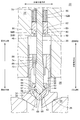
- FIG. 4 is a diagram showing a fully opened state of the valve shown in FIG. 3. It is a figure which shows the state which has shifted the valve shown in FIG. 3 from the valve opening position to the valve closing position.
- valves according to some embodiments are used as steam valves for steam turbine equipment will be described as an example. However, the valves according to some embodiments may be used for applications other than steam turbine equipment. It may be used, and may be used for control of fluids other than steam.
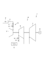
- FIG. 1 is a schematic configuration diagram of a steam turbine facility to which a valve according to an embodiment is applied.
- the steam turbine facility 1 is driven by a boiler 2 for generating steam, a steam turbine 4 that converts the pressure of steam from the boiler 2 into rotational energy, and rotation of the steam turbine 4.
- a generator 8 In the embodiment shown in FIG. 1, the steam turbine 4 includes a high-pressure steam turbine 5, an intermediate-pressure steam turbine 6, and a low-pressure steam turbine 7, and between the high-pressure steam turbine 5 and the intermediate-pressure steam turbine 6.
- a reheater 9 is provided. The steam discharged from the high pressure steam turbine 5 is reheated by the reheater 9 and supplied to the intermediate pressure steam turbine 6. Further, the steam discharged from the intermediate pressure steam turbine 6 is supplied to the low pressure steam turbine 7.
- the boiler 2 and the high-pressure steam turbine 5 are connected via a main steam supply pipe 3, and the main steam supply pipe 3 is provided with a steam valve 10 including a stop valve 11 and an adjusting valve 12.
- a steam valve 10 including a stop valve 11 and an adjusting valve 12.
- the stop valve 11 By closing the stop valve 11, the flow of steam supplied from the boiler 2 to the high pressure steam turbine 5 can be blocked. Further, the flow rate of the steam supplied from the boiler 2 to the high-pressure steam turbine 5 can be adjusted by adjusting the opening degree of the control valve 12.
- a stop valve 13 and an adjusting valve 14 are provided in a pipe connecting the reheater 9 and the intermediate pressure steam turbine 6, and the intermediate pressure steam turbine 6 is supplied by the stop valve 13 and the adjusting valve 14. It is possible to cut off the flow of steam or adjust the flow rate of steam.
- the stop valve 11 is a valve 20 described below.
- the stop valve 13, the control valve 12, or the control valve 14 may be the valve 20 described below.
- valve 20 according to some embodiments will be described with reference to FIGS.
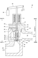
- FIG. 2 is a schematic configuration diagram illustrating an entire valve according to some embodiments.
- the valve 20 accommodates a valve stem 30, a first valve body (child valve) 32 provided on the distal end side of the valve stem 30, and the first valve body 32.
- It is a parent-child valve provided with the 2nd valve body (main valve) 34 which has the interior space 35 to perform, and the valve casing 22 which accommodates the 1st valve body 32 and the 2nd valve body 34.
- An internal space 35 of the second valve body 34 is defined by an inner wall surface 40 of the second valve body 34, and the inner wall surface 40 is a first valve seat (child valve valve seat) 42 on which the first valve body 32 can be seated.
- the valve casing 22 includes a casing main body 23 and a bonnet 24 attached to the casing main body 23, the steam flow path 18 connected from the steam inlet 21 to the steam outlet 29 by the casing main body 23 and the bonnet 24, and the first valve body.
- An accommodation space 25 for the 32 and the second valve body 34 is formed.
- the casing body 23 has a second valve seat (main valve valve seat) 26 on which the second valve body 34 can be seated.
- the bonnet 24 has a through hole 27, and a valve rod 30 is inserted through the through hole 27.
- the second valve body is provided with a passage 44 that communicates the internal space 35 of the second valve body 34 with the steam flow path 18 on the steam inlet 21 side.
- the bonnet 24 is provided with a balance hole 28 for communicating the back side space 46 of the second valve body 34 and the steam flow path 18 on the steam inlet 21 side.
- the bonnet 24 has a first for recovering fluid leaking from the valve body (first valve body 32 and second valve body 34) side to the atmosphere side through the through hole 27 and the valve rod 30.
- a recovery line 48 and a second recovery line 50 are provided.
- the second recovery line 50 is provided at a position farther from the first valve body 32 than the first recovery line 48 and is connected to a fluid reservoir (not shown) having a lower pressure than the first recovery line 48.
- the valve rod 30 is connected to an actuator 38 (for example, a hydraulic actuator) via a lever 36. Further, the valve 20 includes a spring 37 for applying a biasing force in the valve closing direction to the first valve body 32 via the valve rod 30.
- an actuator 38 for example, a hydraulic actuator
- the first valve body 32 and the second valve body 34 are driven via the valve rod 30.
- the first valve body 32 and the second valve body 34 are urged toward the first valve seat 42 and the second valve seat 26 (toward the valve closing direction) by the spring 37. ing.
- the actuator 38 When the valve 20 is opened, the actuator 38 is operated (for example, in the case of a hydraulic actuator, oil is supplied to the hydraulic chamber), and the driving force in the direction opposite to the biasing force of the spring 37 is applied to the valve rod via the lever 36. 30. Then, when the driving force applied to the valve rod 30 by the actuator 38 overcomes the urging force of the spring 37, first, the first valve body 32 moves in the valve opening direction together with the valve rod 30, and the first valve body 32 is moved. Moves away from the first valve seat 42. At this time, the second valve body 34 remains seated on the second valve seat 26. Thereafter, the valve stem side contact surface 72 (see FIG. 3) of the valve stem 30 and the main valve side contact surface 74 (see FIG.
- valve 20 when the valve 20 is opened, if the first valve body 32 moves away from the first valve seat 42 in the state in which the second valve body 34 is seated on the second valve seat 26, the second valve body 34 moves.
- the steam flow path 18 and the back side space 46 of the second valve body 34 communicate with each other via a passage 44 provided in the body 34 and a balance hole 28 provided in the bonnet 24.
- the pressure difference before and behind the 2nd valve body 34 becomes small, and the 2nd valve body 34 can be opened, without giving big driving force with the actuator 38 grade
- the actuator 38 is operated (for example, in the case of a hydraulic actuator, oil is discharged from the hydraulic chamber), and the driving force in the valve opening direction applied to the valve rod by the actuator 38 via the lever 36. Decrease. Then, the first valve body 32 and the second valve body 34 move toward the first valve seat 42 and the second valve seat 26 by the urging force of the spring 37 and the like, and are seated. In this way, the valve 20 is closed.
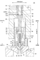
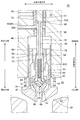
- 3 and 4 are each a configuration diagram illustrating a main part of the valve according to the embodiment.
- 3 and 4 are views showing a fully closed state of the valve (that is, a state where both the first valve body 32 and the second valve body 34 are in the valve closing position).
- 5 is a view showing a fully opened state of the valve shown in FIG. 3 (that is, a state where both the first valve body 32 and the second valve body 34 are in the valve open position)
- FIG. 6 is a view shown in FIG. It is a figure which shows the state which has moved to the valve closing position from the valve opening position. 3 to 6, the illustration of the balance hole is omitted.
- the first recovery line 48 and the second recovery line 50 are not shown.
- the second valve body 34 includes a first bush 86 that is located on the outer peripheral side of the valve stem 30 and guides the valve stem 30 in the axial direction of the valve stem 30.
- the first bush 86 is provided separately from the second valve body 34 and attached to the second valve body.
- the first bush 86 may be provided integrally with the second valve body 34.
- the bonnet 24 (valve casing 22) includes a second bush 92 that is positioned on the outer peripheral side of the valve stem 30 and guides the valve stem 30 in the axial direction of the valve stem 30.
- the bonnet 24 is located on the outer peripheral side of the second valve body 34, and on the outer peripheral side of the valve stem 30, a sleeve 76 for guiding the sliding of the second valve body 34 in the axial direction (valve opening / closing direction). And a sleeve 78 for guiding the valve stem 30 in the axial direction.
- the valve 20 is provided on the proximal end side with respect to the distal side on which the secondary valve surfaces 98A and 98B along the direction intersecting the axial direction of the valve stem 30 and the first valve body 32 are provided.
- the auxiliary seat portions 33A and 33B and an urging member capable of generating an urging force along the axial direction of the valve rod 30 are provided.
- the sub seat portions 33A and 33B are configured to contact the sub seat surfaces 98A and 33B when the first valve body 32 is opened.
- One of the first valve body 32 or the sub seat portions 33A and 33B can be displaced relative to the valve stem 30 in the axial direction of the valve stem 30, and the first valve seat 42 or the sub seat surface by the urging member. It is biased toward one of 98A and 33B.
- the end surface on the proximal end side of the valve stem 30 of the second bush 92 forms the sub seat surface 98 ⁇ / b> A, and is integrated with the valve stem 30 on the outer peripheral side of the valve stem 30.
- the distal end side end surface of the enlarged diameter portion 31 provided so as to move in a straight line forms a sub-sheet portion 33A.
- a spring 62 ⁇ / b> A as an urging member is provided between the first valve body 32 and the valve rod 30.
- a valve stem hole 60 extending in the axial direction of the valve stem 30 is provided on the distal end side of the valve stem 30 so as to open to the distal end surface 70 of the valve stem 30, and the spring 62 ⁇ / b> A is connected to the valve stem hole 60.
- the first valve body 32 can be displaced relative to the valve stem 30 in the axial direction of the valve stem 30, and a first valve seat is provided by a spring 62 ⁇ / b> A provided between the first valve body 32 and the valve stem 30. It is biased toward 42.
- the enlarged diameter portion 31 may be provided integrally with the valve stem 30. Alternatively, the enlarged diameter portion 31 provided separately from the valve stem 30 may be attached to the outer peripheral side of the valve stem 30.
- the first valve body 32 can be displaced relative to the valve stem 30 in the axial direction of the valve stem 30 and is biased toward the first valve seat 42 by the spring 62A.
- the sub seat portion 33A comes into contact with the sub seat surface 98A, and the first valve body 32 is pressed against the first valve seat 42 by the spring 62A.
- both the first valve body 32 and the sub-seat portion 33A can be surely sealed, and in the valve 20, the leakage of fluid to the atmosphere side through the gap between the through hole 27 and the valve rod 30 can be reduced. it can.
- the bonnet 24 (valve casing 22) has a shaft extending in the axial direction on the proximal side of the valve stem 30 from the second bush 92.
- Directional holes 85 are provided.
- a movable piece 82 that is movable along the axial direction of the valve rod 30 inside the axial hole 85 is provided inside the axial hole 85.
- a concave portion 83 extending along the axial direction is provided on the inner peripheral side of the movable piece 82.
- the valve stem 30 is provided with a convex portion 80 in the concave portion 83 so as to protrude in the radial direction of the valve stem 30, and the convex portion 80 engages with the concave portion 83 and is opposed to the movable piece 82. It is slidable in the axial direction. Since the convex portion 80 is slidable in the axial direction with respect to the movable piece 82, the convex portion 80 moves the movable piece 82 when the first valve body 32 and the second valve body 34 move in the valve opening direction. By pushing up in the axial direction and compressing the spring 62B, the sheet of the sub-sheet portion 33B is released.
- the end surface of the second bush 92 on the base end side of the valve stem 30 forms a sub seat surface 98B
- the end surface of the movable piece 82 on the front end side of the valve stem 30 forms a sub seat portion 33B.
- a spring 62 ⁇ / b> B as an urging member is provided on the proximal side of the valve rod 30 with respect to the movable piece 82 inside the axial hole 85.
- the sub seat portion 33B can be displaced relative to the valve stem 30 in the axial direction of the valve stem 30, and is biased toward the sub seat surface 98B by the spring 62B.
- the secondary seat portion 33B can be displaced relative to the valve stem 30 in the axial direction of the valve stem 30 and is biased toward the secondary seat surface 98B by the spring 62B.
- the first valve body 32 is closed, the first valve body 32 is seated on the first valve seat 42, and the sub seat portion 33B is pressed against the sub seat surface 98B by the spring 62B. Therefore, both the first valve body 32 and the sub-seat portion 33B can be reliably sealed, and in the valve 20, fluid leakage to the atmosphere side through the gap between the through hole 27 and the valve rod 30 can be reduced. it can.
- the valve stem 30 has a valve stem side engaging portion including a convex portion or a concave portion protruding or recessed in the radial direction of the valve stem 30 on the distal end side of the valve stem 30 and the first valve.
- the body 32 has a valve body side engaging portion including a concave portion or a convex portion that is depressed or protruded in the radial direction so as to engage with the valve rod side engaging portion, and the valve rod side engaging portion is a first portion.
- the valve body 32 is loosely fitted to the valve body side engaging portion so as to allow relative displacement in the axial direction of the valve body 30 with respect to the valve body 30.
- the valve stem 30 has a convex portion 52 (valve stem side engaging portion) protruding in the radial direction of the valve stem 30 on the distal end side of the valve stem 30, and the first valve
- the body 32 has a concave portion 58 (valve element side engaging portion) that is recessed in the radial direction of the valve stem 30 so as to engage with the convex portion 52.
- the convex portion 52 (valve stem side engaging portion) is loosely fitted to the concave portion 58 (valve side engaging portion) so as to allow relative displacement in the axial direction of the first valve body 32 with respect to the valve stem 30.
- the convex portion 52 (valve stem side engaging portion) faces the valve opening side (valve opening direction) in the axial direction of the valve stem 30, and the first valve body 32.
- a second surface 56 facing the first valve body 32 facing the valve closing side (valve closing direction) in the axial direction of the valve rod 30.
- a gap (55 or 57) is provided between at least one of the first surface 54 and the first valve body 32 or between the second surface 56 and the first valve body 32.
- the convex portion 52 (valve stem side engaging portion) is loosely fitted to the concave portion 58 (valve body side engaging portion), and the convex portion 52 (valve stem side engaging portion) in the axial direction of the valve stem 30.
- a gap is formed between the joint portion) and the recess 58 (valve element side engaging portion)
- relative displacement in the axial direction of the first valve element 32 with respect to the valve stem 30 is allowed. Therefore, the first valve body 32 can be appropriately pressed against the first valve seat 42 by the urging force of the spring 62A that is the urging member, and the first valve body 32 and the sub seat portion 33A can be reliably sealed.
- a first gap 55 is provided between the first valve body 32 and a second gap 57 is provided between the second surface 56 and the first valve body 32.
- a first gap 55 is formed between the first surface 54 facing the valve opening side of the convex portion (valve rod side engaging portion) and the first valve body 32.
- a second gap 57 is formed between the second surface 56 facing the valve closing side of the convex portion (valve stem side engaging portion) and the first valve body 32.
- the second gap 57 is formed on the valve closing side with respect to the convex portion (valve rod side engaging portion), so that the first valve body 32 and the sub seat portion 33A are formed. Even when the seats cannot be seated at the same time, a good seal can be realized in both the first valve body 32 and the sub-seat portion 33A. Further, the second gap 57 can absorb a difference in thermal elongation between various components including the valve stem 30 and the first valve body 32.
- the spring 62 ⁇ / b> A as the biasing member is inside the valve stem hole 60 that extends in the axial direction of the valve stem 30 so as to open to the distal end surface 70 of the valve stem 30.
- an axial biasing force can be applied to the first valve body 32 by the spring 62A guided by the valve stem hole 60 extending in the axial direction of the valve stem 30.
- the valve 20 further includes a biasing force receiving portion 64 that is located between the first valve body 32 and the spring 62 ⁇ / b> A and transmits the biasing force of the spring 62 ⁇ / b> A to the first valve body 32.
- the urging force receiving portion 64 is engaged with the valve stem hole 60, and is guided in the axial direction of the valve stem 30 by the valve stem hole 60. In this way, by applying an urging force along the axial direction to the first valve body 32 via the urging force receiving portion 64 configured to be guided in the axial direction by the valve stem hole 60, the first valve The body 32 can be appropriately pressed by the first valve seat 42.
- the urging force receiving portion 64 has a spherical shape portion 66 at least partially on the first valve body 32 side, and is configured to contact the first valve body 32 at the spherical shape portion 66.
- the stress concentration can be relaxed, and the life of the biasing force receiving portion 64 or the first valve body 32 can be improved.
- the urging force receiving portion 64 has a protrusion 68 that engages with a groove 69 formed in the first valve body 32 so as to be recessed in the axial direction of the valve rod 30.
- the groove 69 and the protrusion 68 are provided so as to pass through the axial center of the valve stem 30.
- the projection 68 that engages with the groove 69 formed in the first valve body 32 so as to be recessed in the axial direction of the valve stem 30 ensures that the center position of the biasing force receiving portion 64 is aligned with the central axis of the valve stem 30. Can be matched.
- valve body 34 when the second valve body 34 is in the valve opening position away from the second valve seat 26, one of the valve stem 30 or the first valve body 32 is in the valve opening direction of the first valve body 32.
- the second valve body 34 is configured to be biased.
- “when the valve body is in the valve open position” may mean that the valve body is at an arbitrary position away from the valve seat. It may mean that it is in a specific position apart. That is, “when the valve body is in the valve open position” means that the valve body is in at least one position among the positions away from the valve seat.
- the second valve body 34 is formed between the first bush 86 provided on the second valve body 34 and the valve stem 30 when the second valve body 34 is in the valve open position (see FIG. 5).
- the first chamber 88 is configured to have a pressure lower than the pressure in the internal space 35 of the second valve body 34 in which the first valve body 32 is accommodated.
- valve stem 30 has a communication passage 90 extending in the axial direction inside the valve stem 30, and when the second valve body 34 is in the valve open position (see FIG. 5), The first chamber 88 and the second chamber 89 having a lower pressure than the first chamber 88 communicate with each other through the passage 90.
- the second chamber 89 has a first recovery line 48 for recovering leaked fluid through the gap between the second bush 92 provided in the valve casing 22 and the valve stem 30. Formed by.
- the valve stem 30 includes a pair of communication holes (94, 96) connected to both ends of the communication passage 90 and extending in the radial direction of the valve stem 30.
- the pair of communication holes are a first communication hole 94 located on the first valve body 32 side of these communication holes, and a first position located on the opposite side of the first valve body 32 (the base end side of the valve rod 30).
- 2 communication holes 96 are a first communication hole 94 located on the first valve body 32 side of these communication holes, and a first position located on the opposite side of the first valve body 32 (the base end side of the valve rod 30).
- 2 communication holes 96 are a first communication hole 94 located on the first valve body 32 side of these communication holes, and a first position located on the opposite side of the first valve body 32 (the base end side of the valve rod 30).
- 2 communication holes 96 are a first communication hole 94 located on the first valve body 32 side of these communication holes, and a first position located on the opposite side of the first valve body 32 (the base end
- FIG. 5 when the second valve element 34 is in the valve open position away from the second valve seat 26, the first communication hole 94 of the communication passage 90 provided inside the valve rod 30 is the first communication hole 94. While communicating with the first chamber 88, the second communication hole 96 communicates with the first recovery line 48 that is the second chamber 89. Thereby, the first chamber 88 formed on the back side of the first valve body 32 is connected to the first recovery line 48 which is the second chamber 89 having a lower pressure than the internal space 35 via the communication passage 90. The first chamber 88 has a lower pressure than the pressure in the internal space 35 of the second valve body 34.
- the urging force in the valve opening direction of the first valve body 32 based on the pressure difference between the first chamber 88 and the internal space 35 of the second valve body 34 acts on the valve rod 30.
- the first communication hole 94 opens to the valve rod 30 on the valve opening direction side of the valve rod side contact surface 72 and communicates with the first chamber 88.
- the second valve body 34 While being held on the valve opening direction side of the valve body 32, the second valve body 34 moves in the valve closing direction together with the second valve body 34 (a process of transition from the state of FIG. 5 to the state of FIG. 6). Then, as shown in FIG. 6, after the second valve body 34 is seated on the second valve seat 26, the valve rod 30 is further moved in the valve closing direction, and the first valve body 32 is seated on the first valve seat 42 ( (The state shown in FIG. 3 is obtained).
- the second valve body 34 and the first valve body 32 are seated in stages when the valve is closed, the second valve body 34 and the first valve body 32 are seated integrally (for example, the first valve body 32).
- the mass of the valve body that collides with the valve seat is reduced.
- the first chamber 88 is a lift gap for lifting the valve rod 30 and the first valve body 32 relative to the second valve body 34.
- a part of the lift gap is defined by the valve stem side contact surface 72 of the valve stem 30 and the first bush 86.
- the lift gap for lifting the valve rod 30 and the first valve body 32 relative to the second valve body 34 is used to make the first pressure lower than the internal space 35 of the second valve body 34.
- a chamber 88 can be formed.
- the first chamber 88 and the first recovery line 48 which is the second chamber 89, are configured not to communicate with each other when the second valve body 34 is in the valve closing position. That is, the communication path 90 and the first collection line 48 that is the second chamber 89 are separated from each other by the contact portion formed by the contact between the sub-sheet portion 33A and the sub-sheet surface 98A. Yes.
- the second recovery line 50 is provided in the valve casing 22 at a position farther from the first valve body 32 than the first recovery line 48.
- the recovery line 50 is connected to a fluid reservoir (not shown) having a lower pressure than the first recovery line 48.
- the valve 20 when the valve 20 includes the second recovery line 50 in addition to the first recovery line 48, the leaked fluid through the gap between the second bush 92 and the valve stem 30 can be recovered by the first recovery line 48. Even if not, the leaked fluid can be recovered through the second recovery line 50 without being released to the atmosphere.
- the valve stem 30 when the valve stem 30 starts to move in the valve opening direction in the fully closed state of the valve (that is, in a state where both the first valve body 32 and the second valve body 34 are in the closed position).
- the first chamber 88 and the second chamber 89 having a lower pressure than the first chamber 88 communicate with each other through the communication passage 90, and the first chamber 88 has a lower pressure than the pressure in the internal space 35 of the second valve body 34. .
- the inflow of leak fluid from the internal space 35 is promoted between the first bush 86 and the valve stem 30, the slidability between the first bush 86 and the valve stem 30 is improved, and the valve stem 30 is compared. It can be moved with a small driving force.
- an expression representing a relative or absolute arrangement such as “in a certain direction”, “along a certain direction”, “parallel”, “orthogonal”, “center”, “concentric” or “coaxial”. Represents not only such an arrangement strictly but also a state of relative displacement with tolerance or an angle or a distance to obtain the same function.
- an expression indicating that things such as “identical”, “equal”, and “homogeneous” are in an equal state not only represents an exactly equal state, but also has a tolerance or a difference that can provide the same function. It also represents the existing state.
- expressions representing shapes such as quadrangular shapes and cylindrical shapes not only represent shapes such as quadrangular shapes and cylindrical shapes in a strict geometric sense, but also within a range where the same effects can be obtained.
- a shape including an uneven portion or a chamfered portion is also expressed.
- the expression “comprising”, “including”, or “having” one constituent element is not an exclusive expression for excluding the existence of another constituent element.
Landscapes
- Engineering & Computer Science (AREA)
- General Engineering & Computer Science (AREA)
- Mechanical Engineering (AREA)
- Lift Valve (AREA)
- Control Of Turbines (AREA)
Abstract
Description
例えば、特許文献1には、蒸気タービンに用いられる蒸気弁が開示されている。この蒸気弁では、閉弁時に、弁体のシート面が弁座に着座することによって蒸気の流れが遮断されるとともに、弁体が接続される弁棒と、該弁棒が挿通されるボンネットとの間を通る蒸気のリークを防止するために、弁棒の拡径部に設けられたバックシートがボンネットに当接するようになっている。
この点、特許文献1には、2か所のシート部分のシート不良に関する対策は具体的に記載されていない。
弁棒と、
前記弁棒の先端側に設けられ、前記弁棒を介して駆動されるように構成された第1弁体と、
前記第1弁体が着座可能である第1弁座と、
前記弁棒の軸方向に交差する方向に沿った副シート面と、
前記第1弁体に対して前記弁棒の基端側に設けられ、前記第1弁体の閉弁時に前記副シート面に当接するように構成された副シート部と、
前記弁棒の前記軸方向に沿った付勢力を生成可能な付勢部材と、を備え、
前記第1弁体又は前記副シート部の一方は、前記弁棒に対して前記軸方向に相対変位可能であり、前記付勢部材によって前記第1弁座又は前記副シート面の一方に向かって付勢される。
前記第1弁体は、前記弁棒に対して前記軸方向に相対変位可能であり、前記第1弁体と前記弁棒との間に設けられた前記付勢部材によって前記第1弁座に向かって付勢される。
前記弁棒は、前記先端側において、前記弁棒の半径方向に突出又は陥没した凸部又は凹部を含む弁棒側係合部を有し、
前記第1弁体は、前記弁棒側係合部と係合するように前記半径方向に陥没又は突出した凹部又は凸部を含む弁体側係合部を有し、
前記弁棒側係合部は、前記第1弁体の前記弁棒に対する前記軸方向における相対変位を許容するように、前記弁体側係合部に対して遊嵌されている。
前記弁棒は、前記半径方向外側に突出する前記凸部を前記弁棒側係合部として有し、
前記弁棒側係合部としての前記凸部は、
前記弁棒の前記軸方向の弁開側を向いて前記第1弁体と対向する第1面と、
前記弁棒の前記軸方向の弁閉側を向いて前記第1弁体と対向する第2面と、
を有し、
前記第1面と前記第1弁体との間、又は、前記第2面と前記第1弁体との間の少なくとも一方に隙間が設けられる。
前記第1弁体が前記第1弁座に着座しているとき、前記第1面と前記第1弁体との間、及び、前記第2面と前記第1弁体との間の両方に隙間が設けられる。
第1弁体の閉弁時において弁棒側係合部(凸部)に対して弁開側に第1隙間が形成されることで、バルブへの流体(例えば蒸気)の流入停止に伴う弁棒の温度低下に起因して弁棒が縮む際、第1弁体が弁棒によって持ち上げられてしまうことを防止することができる。また、第1弁体の調芯性を保持することができる。
一方、第1弁体の閉弁時において弁棒側係合部(凸部)に対して弁閉側に第2隙間が形成されることで、第1弁体及び副シート部が同時着座できない場合であっても、第1弁体及び副シート部の両方での良好なシールを実現できる。また、第2隙間によって、弁棒および第1弁体を含む各種部品間の熱伸び差を吸収することができる。
前記弁棒は、前記先端側において、前記弁棒の先端面に開口するように前記軸方向に延在する弁棒穴を有し、
前記付勢部材は、前記弁棒穴の内部に設けられたばねである。
前記第1弁体と前記付勢部材との間に位置して前記付勢力を前記第1弁体に伝えるとともに、前記弁棒穴に係合して前記弁棒穴によって前記軸方向に案内されるように構成された付勢力受け部をさらに備える。
前記付勢力受け部は、前記第1弁体側において少なくとも部分的に球面形状を有し、該球面形状の部分において前記第1弁体と接するように構成されている。
前記付勢力受け部は、前記弁棒の前記軸方向に向かって凹むように前記第1弁体に形成された溝に係合する突起を有する。
前記第1弁座を形成する内壁面を有し、該内壁面によって画定される内部空間に前記第1弁体を収容する第2弁体と、
前記第2弁体が着座可能である第2弁座を有する弁ケーシングと、
を備え、
前記第2弁体が前記第2弁座から離れた開弁位置にあるとき、前記弁棒又は前記第1弁体の一方が前記第1弁体の開弁方向に前記第2弁体に対して付勢されるように構成される。
前記第2弁体は、前記弁棒の外周側に位置し、前記弁棒を該弁棒の前記軸方向に案内するための第1ブッシュを含み、
前記第2弁体が前記開弁位置にあるとき、前記第1ブッシュと前記弁棒との間に形成される第1室が、前記第1弁体が収容される前記第2弁体の前記内部空間の圧力よりも低圧となるように構成される。
前記第1室は、前記第2弁体に対して前記弁棒及び前記第1弁体をリフトするためのリフト用隙間である。
前記弁棒は、前記弁棒の内部おいて前記軸方向に延びる連通路を有し、
前記第2弁体が前記開弁位置にあるとき、前記連通路を介して、前記第1室と、前記第1室よりも低圧の第2室とが連通され、
前記第2弁体が閉弁位置にあるとき、前記第1室と前記第2室とが連通しないように構成される。
一方、上記(13)の構成では、第2弁体が閉弁位置にあるとき、第1室と第2室とが連通しないようになっているので、第1室から第2室に向かう流体のリーク流れが遮断される。これにより、第2弁体の内部空間からの弁棒と第1ブッシュとの間を介した流体のリークを低減することができる。
前記弁ケーシングは、前記弁棒の前記軸方向に対して交差する方向に沿った前記副シート面を有し、
前記弁棒は、前記第2弁体が前記閉弁位置にあるときに前記副シート面に当接可能な前記副シート部を含み、
前記第2弁体が前記閉弁位置にあるとき、前記連通路と前記第2室とは、前記副シート部及び前記副シート面の当接部によって隔てられるように構成される。
前記(1)乃至(14)の何れに記載のバルブと、
前記バルブの下流側に設けられる蒸気タービンと、
を備える。
なお、以下においては、幾つかの実施形態に係るバルブが蒸気タービン設備の蒸気弁として用いられる場合を一例として説明するが、幾つかの実施形態に係るバルブは、蒸気タービン設備以外の用途に用いられるものであってもよく、蒸気以外の流体の制御に用いられるものであってもよい。
図1に示すように、蒸気タービン設備1は、蒸気を生成するためのボイラ2と、ボイラ2からの蒸気の圧力を回転エネルギーに変換する蒸気タービン4と、蒸気タービン4の回転により駆動される発電機8と、を含む。
図1に示す実施形態では、蒸気タービン4は、高圧蒸気タービン5と、中圧蒸気タービン6と、低圧蒸気タービン7と、を含み、高圧蒸気タービン5と中圧蒸気タービン6との間には、再熱器9が設けられる。高圧蒸気タービン5から排出された蒸気は、再熱器9により再加熱されて、中圧蒸気タービン6に供給されるようになっている。また、中圧蒸気タービン6から排出された蒸気は、低圧蒸気タービン7に供給されるようになっている。
また、再熱器9と中圧蒸気タービン6とを接続する配管には止め弁13及び加減弁14が設けられており、これらの止め弁13及び加減弁14によって、中圧蒸気タービン6に供給される蒸気の流れを遮断し、あるいは蒸気の流量を調節することが可能となっている。
幾つかの実施形態において、止め弁11は以下に説明するバルブ20である。幾つかの実施形態では、止め弁13、加減弁12、又は加減弁14が以下に説明するバルブ20であってもよい。
第2弁体34の内部空間35は、第2弁体34の内壁面40により画定され、該内壁面40は、第1弁体32が着座可能な第1弁座(子弁弁座)42を形成する。
ケーシング本体23は、第2弁体34が着座可能な第2弁座(主弁弁座)26を有する。ボンネット24は貫通孔27を有し、該貫通孔27には弁棒30が挿通されている。
ボンネット24には、第2弁体34の背面側空間46と、蒸気入口21側の蒸気流路18とを連通させるバランス孔28が設けられている。
バルブ20の閉状態においては、第1弁体32及び第2弁体34は、スプリング37により、第1弁座42及び第2弁座26に向かって(閉弁方向に向かって)付勢されている。
なお、図3~図6において、バランス孔の図示は省略されている。また、図4において、第1回収ライン48及び第2回収ライン50の図示は省略されている。
また、ボンネット24(弁ケーシング22)には、弁棒30の外周側に位置し、弁棒30を弁棒30の軸方向に案内するための第2ブッシュ92を含む。
また、ボンネット24は、第2弁体34の外周側に位置し、第2弁体34の軸方向(弁開閉方向)の摺動を案内するためのスリーブ76と、弁棒30の外周側に位置し、弁棒30を弁棒30を軸方向に案内するためのスリーブ78と、を含む。
また、付勢部材としてのばね62Aが、第1弁体32と弁棒30との間に設けられている。弁棒30の先端側には、弁棒30の先端面70に開口するように弁棒30の軸方向に延在する弁棒穴60が設けられており、ばね62Aは、該弁棒穴60の内部に設けられている。
そして、第1弁体32は、弁棒30に対して弁棒30の軸方向に相対変位可能であり、第1弁体32と弁棒30との間に設けられたばね62Aによって第1弁座42に向かって付勢されている。
なお、拡径部31は、弁棒30と一体的に設けられていてもよい。あるいは、弁棒30とは別体として設けられた拡径部31が弁棒30の外周側に取付けられていてもよい。
また、付勢部材としてのばね62Bが、軸方向穴85の内部において該可動片82よりも弁棒30基端側に設けられている。
そして、副シート部33Bは、弁棒30に対して弁棒30の軸方向に相対変位可能であり、ばね62Bによって副シート面98Bに向かって付勢されている。
第1弁体32の閉弁時において凸部(弁棒側係合部)に対して弁開側に第1隙間55が形成されることで、バルブ20への流体(例えば蒸気)の流入停止に伴う弁棒の温度低下に起因して弁棒30が縮む際、第1弁体32が弁棒30によって持ち上げられてしまうことを防止することができる。
一方、第1弁体32の閉弁時において凸部(弁棒側係合部)に対して弁閉側に第2隙間57が形成されることで、第1弁体32及び副シート部33Aが同時着座できない場合であっても、第1弁体32及び副シート部33Aの両方での良好なシールを実現できる。また、第2隙間57によって、弁棒30および第1弁体32を含む各種部品間の熱伸び差を吸収することができる。
この場合、弁棒30の軸方向に延在する弁棒穴60によって案内されたばね62Aにより、第1弁体32に対して軸方向の付勢力を与えることができる。これにより、ばね62Aによって第1弁体32が第1弁座42に適切に押し付けられるので、第1弁体32及び副シート部33Aの両方で確実にシールできる。
このように、弁棒穴60によって軸方向に案内されるように構成された付勢力受け部64を介して、軸方向に沿った付勢力を第1弁体32に与えることで、第1弁体32を第1弁座42により適切に押し付けることができる。
この場合、角部を持つ部分において第1弁体32と接する場合に比べて、応力集中を緩和することができ、付勢力受け部64又は第1弁体32の寿命を向上させることができる。
弁棒30の軸方向に向かって凹むように第1弁体32に形成された溝69に係合する突起68により、付勢力受け部64の中心位置を、弁棒30の中心軸に確実に合わせることができる。これにより、軸方向に沿った付勢力を第1弁体32に確実に与えて、第1弁体32を第1弁座42により確実に押し付けることができる。このため、バルブ20において第1弁体32及び副シート部33Aの両方で確実にシールできる。
本明細書において、弁体が「開弁位置にあるとき」とは、弁体が弁座から離れた任意の位置にあるときに、との意味であってもよく、弁体が弁座から離れた特定の位置にあるときに、との意味であってもよい。すなわち、弁体が「開弁位置にあるとき」とは、弁体が弁座から離れた位置のうち少なくとも1つの位置において、との意味である。
図3に示す例示的な実施形態では、第2室89は、弁ケーシング22に設けられた第2ブッシュ92と弁棒30との隙間を介したリーク流体を回収するための第1回収ライン48によって形成される。
そして、第2弁体34が開弁位置にあるとき(図5参照)、一対の連通穴(94,96)のうち第1弁体32側に位置する第1連通穴94が第1室88に連通し、一対の連通穴の(94,96)うち第2連通穴96が第2室89(図3に示す例では第1回収ライン48)に連通するように構成されている。
まず、図5に示すように、第2弁体34が第2弁座26から離れた開弁位置にあるときには、弁棒30の内部に設けられた連通路90の第1連通穴94が第1室88に連通するとともに、第2連通穴96が第2室89である第1回収ライン48に連通される。
これにより、第1弁体32の背面側に形成される第1室88が、連通路90を介して、内部空間35よりも低圧の第2室89である第1回収ライン48と接続され、第1室88は、第2弁体34の内部空間35の圧力よりも低圧となる。よって、弁棒30には、第1室88と第2弁体34の内部空間35との圧力差に基づく第1弁体32の開弁方向の付勢力が作用する。第1連通穴94は、弁棒側当接面72よりも開弁方向側で弁棒30に開口し、第1室88と連通する。
そして、図6に示すように第2弁体34が第2弁座26に着座した後に、弁棒30がさらに閉弁方向に動き、第1弁体32が第1弁座42に着座する(図3に示す状態となる)。
このように、第2弁体34に対して弁棒30及び第1弁体32をリフトするためのリフト用隙間を利用して、第2弁体34の内部空間35よりも低圧となる第1室88を形成することができる。
これにより、第1ブッシュ86と弁棒30との間に内部空間35からのリーク流体の流入が促進され、第1ブッシュ86と弁棒30との摺動性が向上し、弁棒30を比較的小さな駆動力で移動させることができるようになる。
例えば、「同一」、「等しい」及び「均質」等の物事が等しい状態であることを表す表現は、厳密に等しい状態を表すのみならず、公差、若しくは、同じ機能が得られる程度の差が存在している状態も表すものとする。
また、本明細書において、四角形状や円筒形状等の形状を表す表現は、幾何学的に厳密な意味での四角形状や円筒形状等の形状を表すのみならず、同じ効果が得られる範囲で、凹凸部や面取り部等を含む形状も表すものとする。
また、本明細書において、一の構成要素を「備える」、「含む」、又は、「有する」という表現は、他の構成要素の存在を除外する排他的な表現ではない。
2 ボイラ
3 主蒸気供給配管
4 蒸気タービン
5 高圧蒸気タービン
6 中圧蒸気タービン
7 低圧蒸気タービン
8 発電機
9 再熱器
10 蒸気弁
11 止め弁
12 加減弁
13 止め弁
14 加減弁
18 蒸気流路
20 バルブ
21 蒸気入口
22 弁ケーシング
23 ケーシング本体
24 ボンネット
25 収容空間
26 第2弁座
27 貫通孔
28 バランス孔
29 蒸気出口
30 弁棒
31 拡径部
32 第1弁体
33A,33B 副シート部
34 第2弁体
35 内部空間
36 レバー
37 スプリング
38 アクチュエータ
40 内壁面
42 第1弁座
44 通路
46 背面側空間
48 第1回収ライン
50 第2回収ライン
52 凸部
54 第1面
55 第1隙間
56 第2面
57 第2隙間
58 凹部
60 弁棒穴
62A,62B ばね
64 付勢力受け部
66 球面形状部
68 突起
69 溝
70 先端面
72 弁棒側当接面
74 主弁側当接面
76 スリーブ
78 スリーブ
80 凸部
82 可動片
83 凹部
85 軸方向穴
86 第1ブッシュ
88 第1室
90 連通路
92 第2ブッシュ
94 第1連通穴
96 第2連通穴
98A,98B 副シート面
Claims (15)
- 弁棒と、
前記弁棒の先端側に設けられ、前記弁棒を介して駆動されるように構成された第1弁体と、
前記第1弁体が着座可能である第1弁座と、
前記弁棒の軸方向に交差する方向に沿った副シート面と、
前記第1弁体に対して前記弁棒の基端側に設けられ、前記第1弁体の閉弁時に前記副シート面に当接するように構成された副シート部と、
前記弁棒の前記軸方向に沿った付勢力を生成可能な付勢部材と、を備え、
前記第1弁体又は前記副シート部の一方は、前記弁棒に対して前記軸方向に相対変位可能であり、前記付勢部材によって前記第1弁座又は前記副シート面の一方に向かって付勢されることを特徴とするバルブ。 - 前記第1弁体は、前記弁棒に対して前記軸方向に相対変位可能であり、前記第1弁体と前記弁棒との間に設けられた前記付勢部材によって前記第1弁座に向かって付勢されることを特徴とする請求項1に記載のバルブ。
- 前記弁棒は、前記先端側において、前記弁棒の半径方向に突出又は陥没した凸部又は凹部を含む弁棒側係合部を有し、
前記第1弁体は、前記弁棒側係合部と係合するように前記半径方向に陥没又は突出した凹部又は凸部を含む弁体側係合部を有し、
前記弁棒側係合部は、前記第1弁体の前記弁棒に対する前記軸方向における相対変位を許容するように、前記弁体側係合部に対して遊嵌されていることを特徴とする請求項2に記載のバルブ。 - 前記弁棒は、前記半径方向外側に突出する前記凸部を前記弁棒側係合部として有し、
前記弁棒側係合部としての前記凸部は、
前記弁棒の前記軸方向の弁開側を向いて前記第1弁体と対向する第1面と、
前記弁棒の前記軸方向の弁閉側を向いて前記第1弁体と対向する第2面と、
を有し、
前記第1面と前記第1弁体との間、又は、前記第2面と前記第1弁体との間の少なくとも一方に隙間が設けられる
ことを特徴とする請求項3に記載のバルブ。 - 前記第1弁体が前記第1弁座に着座しているとき、前記第1面と前記第1弁体との間、及び、前記第2面と前記第1弁体との間の両方に隙間が設けられる
ことを特徴とする請求項4に記載のバルブ。 - 前記弁棒は、前記先端側において、前記弁棒の先端面に開口するように前記軸方向に延在する弁棒穴を有し、
前記付勢部材は、前記弁棒穴の内部に設けられたばねである
ことを特徴とする請求項2乃至5の何れか一項に記載のバルブ。 - 前記第1弁体と前記付勢部材との間に位置して前記付勢力を前記第1弁体に伝えるとともに、前記弁棒穴に係合して前記弁棒穴によって前記軸方向に案内されるように構成された付勢力受け部をさらに備えることを特徴とする請求項6に記載のバルブ。
- 前記付勢力受け部は、前記第1弁体側において少なくとも部分的に球面形状を有し、該球面形状の部分において前記第1弁体と接するように構成された
ことを特徴とする請求項6又は7の何れか一項に記載のバルブ。 - 前記付勢力受け部は、前記弁棒の前記軸方向に向かって凹むように前記第1弁体に形成された溝に係合する突起を有する
ことを特徴とする請求項6乃至8の何れか一項に記載のバルブ。 - 前記第1弁座を形成する内壁面を有し、該内壁面によって画定される内部空間に前記第1弁体を収容する第2弁体と、
前記第2弁体が着座可能である第2弁座を有する弁ケーシングと、
を備え、
前記第2弁体が前記第2弁座から離れた開弁位置にあるとき、前記弁棒又は前記第1弁体の一方が前記第1弁体の開弁方向に前記第2弁体に対して付勢されるように構成された
ことを特徴とする請求項1乃至9の何れか一項に記載のバルブ。 - 前記第2弁体は、前記弁棒の外周側に位置し、前記弁棒を該弁棒の前記軸方向に案内するための第1ブッシュを含み、
前記第2弁体が前記開弁位置にあるとき、前記第1ブッシュと前記弁棒との間に形成される第1室が、前記第1弁体が収容される前記第2弁体の前記内部空間の圧力よりも低圧となるように構成されたことを特徴とする請求項10に記載のバルブ。 - 前記第1室は、前記第2弁体に対して前記弁棒及び前記第1弁体をリフトするためのリフト用隙間であることを特徴とする請求項11に記載のバルブ。
- 前記弁棒は、前記弁棒の内部おいて前記軸方向に延びる連通路を有し、
前記第2弁体が前記開弁位置にあるとき、前記連通路を介して、前記第1室と、前記第1室よりも低圧の第2室とが連通され、
前記第2弁体が閉弁位置にあるとき、前記第1室と前記第2室とが連通しないように構成された
ことを特徴とする請求項11又は12に記載のバルブ。 - 前記弁ケーシングは、前記弁棒の前記軸方向に対して交差する方向に沿った前記副シート面を有し、
前記弁棒は、前記第2弁体が前記閉弁位置にあるときに前記副シート面に当接可能な前記副シート部を含み、
前記第2弁体が前記閉弁位置にあるとき、前記連通路と前記第2室とは、前記副シート部及び前記副シート面の当接部によって隔てられるように構成された
ことを特徴とする請求項13に記載のバルブ。 - 請求項1乃至14の何れか一項に記載のバルブと、
前記バルブの下流側に設けられる蒸気タービンと、
を備えることを特徴とする蒸気タービン設備。
Priority Applications (4)
| Application Number | Priority Date | Filing Date | Title |
|---|---|---|---|
| DE112017002592.3T DE112017002592B4 (de) | 2016-05-20 | 2017-05-19 | Dampfventil und Dampfturbinenanlage |
| US16/099,350 US10941865B2 (en) | 2016-05-20 | 2017-05-19 | Steam valve, valve and steam turbine facility |
| KR1020187032328A KR102091505B1 (ko) | 2016-05-20 | 2017-05-19 | 증기 밸브, 밸브 및 증기 터빈 설비 |
| CN201780028554.4A CN109073094B (zh) | 2016-05-20 | 2017-05-19 | 蒸汽阀、阀及蒸汽轮机设备 |
Applications Claiming Priority (2)
| Application Number | Priority Date | Filing Date | Title |
|---|---|---|---|
| JP2016101334A JP6718306B2 (ja) | 2016-05-20 | 2016-05-20 | バルブ及び蒸気タービン設備 |
| JP2016-101334 | 2016-05-20 |
Publications (1)
| Publication Number | Publication Date |
|---|---|
| WO2017200067A1 true WO2017200067A1 (ja) | 2017-11-23 |
Family
ID=60325959
Family Applications (1)
| Application Number | Title | Priority Date | Filing Date |
|---|---|---|---|
| PCT/JP2017/018760 Ceased WO2017200067A1 (ja) | 2016-05-20 | 2017-05-19 | バルブ及び蒸気タービン設備 |
Country Status (6)
| Country | Link |
|---|---|
| US (1) | US10941865B2 (ja) |
| JP (1) | JP6718306B2 (ja) |
| KR (1) | KR102091505B1 (ja) |
| CN (1) | CN109073094B (ja) |
| DE (1) | DE112017002592B4 (ja) |
| WO (1) | WO2017200067A1 (ja) |
Cited By (2)
| Publication number | Priority date | Publication date | Assignee | Title |
|---|---|---|---|---|
| JP2020056664A (ja) * | 2018-10-01 | 2020-04-09 | 東北発電工業株式会社 | 測定方法、及び、測定補助具 |
| WO2023149088A1 (ja) * | 2022-02-01 | 2023-08-10 | 三菱重工業株式会社 | 蒸気弁、及び発電システム |
Families Citing this family (8)
| Publication number | Priority date | Publication date | Assignee | Title |
|---|---|---|---|---|
| JP7051398B2 (ja) * | 2017-11-30 | 2022-04-11 | 三菱重工業株式会社 | 開閉弁及び蒸気タービンシステム |
| JP7232043B2 (ja) * | 2018-12-28 | 2023-03-02 | 三菱重工業株式会社 | 蒸気弁、及び発電システム |
| JP7207999B2 (ja) | 2018-12-28 | 2023-01-18 | 三菱重工業株式会社 | 蒸気弁、発電システム、及び蒸気弁の検査方法 |
| JP7236272B2 (ja) * | 2018-12-28 | 2023-03-09 | 三菱重工業株式会社 | 蒸気弁、及び発電システム |
| JP7458168B2 (ja) * | 2019-11-14 | 2024-03-29 | 三菱重工業株式会社 | 蒸気弁及び蒸気タービン設備並びに蒸気弁の組立て方法 |
| CN114059318B (zh) * | 2020-08-04 | 2025-06-20 | 青岛海尔滚筒洗衣机有限公司 | 一种阀芯结构及离心阀及洗衣机 |
| US11585449B2 (en) * | 2020-10-21 | 2023-02-21 | Caterpillar Inc. | Pilot operated bypass valve with reverse check |
| DE102022109609B3 (de) * | 2022-04-21 | 2023-08-03 | Otto Egelhof Gmbh & Co. Kg | Ventil zur Steuerung eines Mediums in einem Kälte- oder Wärmekreislauf |
Citations (7)
| Publication number | Priority date | Publication date | Assignee | Title |
|---|---|---|---|---|
| JPS5037027A (ja) * | 1973-06-22 | 1975-04-07 | ||
| JPS57144354A (en) * | 1981-02-27 | 1982-09-06 | Toshiba Corp | Valve mechanism for low temperature |
| JPS58134284A (ja) * | 1982-02-03 | 1983-08-10 | Ishikawajima Harima Heavy Ind Co Ltd | 高温流体遮断弁 |
| JPH02125285U (ja) * | 1989-03-28 | 1990-10-16 | ||
| JPH05965U (ja) * | 1991-06-26 | 1993-01-08 | 株式会社アツギユニシア | 流量制御バルブ |
| JP2003329158A (ja) * | 2002-05-15 | 2003-11-19 | Saginomiya Seisakusho Inc | 電動弁 |
| JP2012021568A (ja) * | 2010-07-14 | 2012-02-02 | Mitsubishi Heavy Ind Ltd | 水平弁 |
Family Cites Families (19)
| Publication number | Priority date | Publication date | Assignee | Title |
|---|---|---|---|---|
| US2733041A (en) | 1956-01-31 | Steam valve | ||
| US433543A (en) * | 1890-08-05 | Automatic relief-valve | ||
| DE515502C (de) | 1928-10-03 | 1931-01-08 | Siemens Schuckertwerke Akt Ges | Durchgangsventil |
| US2666452A (en) * | 1951-12-29 | 1954-01-19 | Gen Electric | Valve actuating mechanism |
| US3459212A (en) * | 1967-05-15 | 1969-08-05 | Donald C Campion Sr | Vented fluid valve |
| US3529630A (en) * | 1968-04-11 | 1970-09-22 | Westinghouse Electric Corp | Combined stop and control valve |
| BR7604063A (pt) * | 1975-08-13 | 1977-06-28 | Kraftwerk Union Ag | Instalacao de reator nuclear |
| JPS58134284U (ja) * | 1982-03-01 | 1983-09-09 | 松下電器産業株式会社 | 真空封止治具 |
| JP2005321061A (ja) | 2004-05-11 | 2005-11-17 | Kubota Corp | 高温用弁 |
| US7219695B2 (en) | 2005-06-17 | 2007-05-22 | General Motors Corporation | Hydrogen valve with pressure equalization |
| DE102005058526B4 (de) | 2005-12-08 | 2019-06-19 | Robert Bosch Gmbh | Zweistufiges Ventil zum Steuern von Fluiden |
| JP4362853B2 (ja) | 2007-06-18 | 2009-11-11 | Smc株式会社 | 2ポート電磁弁 |
| JP6037684B2 (ja) * | 2012-07-02 | 2016-12-07 | 三菱日立パワーシステムズ株式会社 | 蒸気タービン設備 |
| EP2937520B1 (en) * | 2012-12-21 | 2017-09-20 | Mitsubishi Hitachi Power Systems, Ltd. | Steam valve and steam turbine |
| EP2990611B1 (en) * | 2014-02-19 | 2017-08-16 | Mitsubishi Heavy Industries Compressor Corporation | Vapor valve and vapor turbine |
| JP6382556B2 (ja) * | 2014-04-08 | 2018-08-29 | 株式会社東芝 | 蒸気弁 |
| JP6557577B2 (ja) * | 2015-10-30 | 2019-08-07 | 三菱日立パワーシステムズ株式会社 | 蒸気弁及び蒸気タービンシステム |
| JP6606407B2 (ja) * | 2015-11-12 | 2019-11-13 | 三菱日立パワーシステムズ株式会社 | 蒸気弁及び蒸気タービンシステム |
| JP6855846B2 (ja) * | 2017-03-06 | 2021-04-07 | セイコーエプソン株式会社 | ペースト及び三次元造形物の製造方法 |
-
2016
- 2016-05-20 JP JP2016101334A patent/JP6718306B2/ja active Active
-
2017
- 2017-05-19 US US16/099,350 patent/US10941865B2/en active Active
- 2017-05-19 CN CN201780028554.4A patent/CN109073094B/zh active Active
- 2017-05-19 KR KR1020187032328A patent/KR102091505B1/ko active Active
- 2017-05-19 DE DE112017002592.3T patent/DE112017002592B4/de active Active
- 2017-05-19 WO PCT/JP2017/018760 patent/WO2017200067A1/ja not_active Ceased
Patent Citations (7)
| Publication number | Priority date | Publication date | Assignee | Title |
|---|---|---|---|---|
| JPS5037027A (ja) * | 1973-06-22 | 1975-04-07 | ||
| JPS57144354A (en) * | 1981-02-27 | 1982-09-06 | Toshiba Corp | Valve mechanism for low temperature |
| JPS58134284A (ja) * | 1982-02-03 | 1983-08-10 | Ishikawajima Harima Heavy Ind Co Ltd | 高温流体遮断弁 |
| JPH02125285U (ja) * | 1989-03-28 | 1990-10-16 | ||
| JPH05965U (ja) * | 1991-06-26 | 1993-01-08 | 株式会社アツギユニシア | 流量制御バルブ |
| JP2003329158A (ja) * | 2002-05-15 | 2003-11-19 | Saginomiya Seisakusho Inc | 電動弁 |
| JP2012021568A (ja) * | 2010-07-14 | 2012-02-02 | Mitsubishi Heavy Ind Ltd | 水平弁 |
Cited By (7)
| Publication number | Priority date | Publication date | Assignee | Title |
|---|---|---|---|---|
| JP2020056664A (ja) * | 2018-10-01 | 2020-04-09 | 東北発電工業株式会社 | 測定方法、及び、測定補助具 |
| WO2023149088A1 (ja) * | 2022-02-01 | 2023-08-10 | 三菱重工業株式会社 | 蒸気弁、及び発電システム |
| JPWO2023149088A1 (ja) * | 2022-02-01 | 2023-08-10 | ||
| KR20230154321A (ko) * | 2022-02-01 | 2023-11-07 | 미츠비시 파워 가부시키가이샤 | 증기 밸브, 및 발전 시스템 |
| JP7654120B2 (ja) | 2022-02-01 | 2025-03-31 | 三菱重工業株式会社 | 蒸気弁、及び発電システム |
| US12510186B2 (en) | 2022-02-01 | 2025-12-30 | Mitsubishi Heavy Industries, Ltd. | Steam valve and power generation system |
| KR102925370B1 (ko) * | 2022-02-01 | 2026-02-09 | 미츠비시 파워 가부시키가이샤 | 증기 밸브, 및 발전 시스템 |
Also Published As
| Publication number | Publication date |
|---|---|
| JP6718306B2 (ja) | 2020-07-08 |
| CN109073094B (zh) | 2021-03-12 |
| KR20180127499A (ko) | 2018-11-28 |
| JP2017207174A (ja) | 2017-11-24 |
| US20190178388A1 (en) | 2019-06-13 |
| KR102091505B1 (ko) | 2020-03-20 |
| US10941865B2 (en) | 2021-03-09 |
| DE112017002592B4 (de) | 2026-03-26 |
| CN109073094A (zh) | 2018-12-21 |
| DE112017002592T5 (de) | 2019-04-25 |
Similar Documents
| Publication | Publication Date | Title |
|---|---|---|
| WO2017200067A1 (ja) | バルブ及び蒸気タービン設備 | |
| EP2492559B1 (en) | Solenoid valve | |
| WO2016109485A2 (en) | Double piston effect lip seal seating assemblies | |
| CN1746542B (zh) | 蒸汽阀 | |
| JP2017207174A5 (ja) | ||
| JP2014152885A (ja) | ピストン構造パイロット駆動式電磁弁 | |
| JP6713826B2 (ja) | 親子弁及びその閉弁方法並びに蒸気タービン設備 | |
| JP6162335B2 (ja) | ターボ機械のための弁 | |
| JP5982703B2 (ja) | 減圧弁 | |
| JP6773469B2 (ja) | ガス弁装置 | |
| US12510186B2 (en) | Steam valve and power generation system | |
| EP3726032B1 (en) | Bleed valve | |
| JP2010266000A (ja) | 過流防止弁 | |
| JP5722164B2 (ja) | 減圧装置 | |
| JP7458168B2 (ja) | 蒸気弁及び蒸気タービン設備並びに蒸気弁の組立て方法 | |
| JP6218233B2 (ja) | 減圧弁 | |
| KR101741482B1 (ko) | 닫힘 상태에서 조작력 완화구조를 가지는 플로팅 타입 볼 밸브 | |
| JP6367078B2 (ja) | バタフライ弁の止水構造 | |
| JP5712092B2 (ja) | パイロット機能付き弁 | |
| JP5430104B2 (ja) | バルブ付き管継手 | |
| JP2018146103A (ja) | 電磁弁装置 | |
| JP2012172519A (ja) | フラップバルブ | |
| RU2591382C1 (ru) | Клапан | |
| JP2024140547A (ja) | 電磁弁 | |
| US765077A (en) | Self-closing stop-valve. |
Legal Events
| Date | Code | Title | Description |
|---|---|---|---|
| ENP | Entry into the national phase |
Ref document number: 20187032328 Country of ref document: KR Kind code of ref document: A |
|
| WWE | Wipo information: entry into national phase |
Ref document number: 112017002592 Country of ref document: DE |
|
| 121 | Ep: the epo has been informed by wipo that ep was designated in this application |
Ref document number: 17799491 Country of ref document: EP Kind code of ref document: A1 |
|
| 122 | Ep: pct application non-entry in european phase |
Ref document number: 17799491 Country of ref document: EP Kind code of ref document: A1 |
|
| WWG | Wipo information: grant in national office |
Ref document number: 112017002592 Country of ref document: DE |