WO2017169772A1 - エアサスペンションシステム - Google Patents
エアサスペンションシステム Download PDFInfo
- Publication number
- WO2017169772A1 WO2017169772A1 PCT/JP2017/010364 JP2017010364W WO2017169772A1 WO 2017169772 A1 WO2017169772 A1 WO 2017169772A1 JP 2017010364 W JP2017010364 W JP 2017010364W WO 2017169772 A1 WO2017169772 A1 WO 2017169772A1
- Authority
- WO
- WIPO (PCT)
- Prior art keywords
- wheel side
- air
- air suspension
- supply
- tank
- Prior art date
- Legal status (The legal status is an assumption and is not a legal conclusion. Google has not performed a legal analysis and makes no representation as to the accuracy of the status listed.)
- Ceased
Links
Images



Classifications
-
- B—PERFORMING OPERATIONS; TRANSPORTING
- B60—VEHICLES IN GENERAL
- B60G—VEHICLE SUSPENSION ARRANGEMENTS
- B60G17/00—Resilient suspensions having means for adjusting the spring or vibration-damper characteristics, for regulating the distance between a supporting surface and a sprung part of vehicle or for locking suspension during use to meet varying vehicular or surface conditions, e.g. due to speed or load
- B60G17/02—Spring characteristics, e.g. mechanical springs and mechanical adjusting means
- B60G17/04—Spring characteristics, e.g. mechanical springs and mechanical adjusting means fluid spring characteristics
- B60G17/052—Pneumatic spring characteristics
- B60G17/0523—Regulating distributors or valves for pneumatic springs
-
- B—PERFORMING OPERATIONS; TRANSPORTING
- B60—VEHICLES IN GENERAL
- B60G—VEHICLE SUSPENSION ARRANGEMENTS
- B60G17/00—Resilient suspensions having means for adjusting the spring or vibration-damper characteristics, for regulating the distance between a supporting surface and a sprung part of vehicle or for locking suspension during use to meet varying vehicular or surface conditions, e.g. due to speed or load
- B60G17/02—Spring characteristics, e.g. mechanical springs and mechanical adjusting means
- B60G17/04—Spring characteristics, e.g. mechanical springs and mechanical adjusting means fluid spring characteristics
- B60G17/052—Pneumatic spring characteristics
-
- B—PERFORMING OPERATIONS; TRANSPORTING
- B60—VEHICLES IN GENERAL
- B60G—VEHICLE SUSPENSION ARRANGEMENTS
- B60G17/00—Resilient suspensions having means for adjusting the spring or vibration-damper characteristics, for regulating the distance between a supporting surface and a sprung part of vehicle or for locking suspension during use to meet varying vehicular or surface conditions, e.g. due to speed or load
- B60G17/02—Spring characteristics, e.g. mechanical springs and mechanical adjusting means
- B60G17/04—Spring characteristics, e.g. mechanical springs and mechanical adjusting means fluid spring characteristics
- B60G17/0416—Spring characteristics, e.g. mechanical springs and mechanical adjusting means fluid spring characteristics regulated by varying the resiliency of hydropneumatic suspensions
- B60G17/0424—Spring characteristics, e.g. mechanical springs and mechanical adjusting means fluid spring characteristics regulated by varying the resiliency of hydropneumatic suspensions by varying the air pressure of the accumulator
-
- B—PERFORMING OPERATIONS; TRANSPORTING
- B60—VEHICLES IN GENERAL
- B60G—VEHICLE SUSPENSION ARRANGEMENTS
- B60G11/00—Resilient suspensions characterised by arrangement, location or kind of springs
- B60G11/26—Resilient suspensions characterised by arrangement, location or kind of springs having fluid springs only, e.g. hydropneumatic springs
- B60G11/27—Resilient suspensions characterised by arrangement, location or kind of springs having fluid springs only, e.g. hydropneumatic springs wherein the fluid is a gas
-
- B—PERFORMING OPERATIONS; TRANSPORTING
- B60—VEHICLES IN GENERAL
- B60G—VEHICLE SUSPENSION ARRANGEMENTS
- B60G17/00—Resilient suspensions having means for adjusting the spring or vibration-damper characteristics, for regulating the distance between a supporting surface and a sprung part of vehicle or for locking suspension during use to meet varying vehicular or surface conditions, e.g. due to speed or load
- B60G17/015—Resilient suspensions having means for adjusting the spring or vibration-damper characteristics, for regulating the distance between a supporting surface and a sprung part of vehicle or for locking suspension during use to meet varying vehicular or surface conditions, e.g. due to speed or load the regulating means comprising electric or electronic elements
- B60G17/0152—Resilient suspensions having means for adjusting the spring or vibration-damper characteristics, for regulating the distance between a supporting surface and a sprung part of vehicle or for locking suspension during use to meet varying vehicular or surface conditions, e.g. due to speed or load the regulating means comprising electric or electronic elements characterised by the action on a particular type of suspension unit
- B60G17/0155—Resilient suspensions having means for adjusting the spring or vibration-damper characteristics, for regulating the distance between a supporting surface and a sprung part of vehicle or for locking suspension during use to meet varying vehicular or surface conditions, e.g. due to speed or load the regulating means comprising electric or electronic elements characterised by the action on a particular type of suspension unit pneumatic unit
-
- B—PERFORMING OPERATIONS; TRANSPORTING
- B60—VEHICLES IN GENERAL
- B60G—VEHICLE SUSPENSION ARRANGEMENTS
- B60G17/00—Resilient suspensions having means for adjusting the spring or vibration-damper characteristics, for regulating the distance between a supporting surface and a sprung part of vehicle or for locking suspension during use to meet varying vehicular or surface conditions, e.g. due to speed or load
- B60G17/02—Spring characteristics, e.g. mechanical springs and mechanical adjusting means
- B60G17/04—Spring characteristics, e.g. mechanical springs and mechanical adjusting means fluid spring characteristics
- B60G17/052—Pneumatic spring characteristics
- B60G17/0523—Regulating distributors or valves for pneumatic springs
- B60G17/0525—Height adjusting or levelling valves
-
- B—PERFORMING OPERATIONS; TRANSPORTING
- B60—VEHICLES IN GENERAL
- B60G—VEHICLE SUSPENSION ARRANGEMENTS
- B60G17/00—Resilient suspensions having means for adjusting the spring or vibration-damper characteristics, for regulating the distance between a supporting surface and a sprung part of vehicle or for locking suspension during use to meet varying vehicular or surface conditions, e.g. due to speed or load
- B60G17/02—Spring characteristics, e.g. mechanical springs and mechanical adjusting means
- B60G17/04—Spring characteristics, e.g. mechanical springs and mechanical adjusting means fluid spring characteristics
- B60G17/056—Regulating distributors or valves for hydropneumatic systems
- B60G17/0565—Height adjusting valves
-
- B—PERFORMING OPERATIONS; TRANSPORTING
- B60—VEHICLES IN GENERAL
- B60G—VEHICLE SUSPENSION ARRANGEMENTS
- B60G2202/00—Indexing codes relating to the type of spring, damper or actuator
- B60G2202/10—Type of spring
- B60G2202/15—Fluid spring
- B60G2202/152—Pneumatic spring
-
- B—PERFORMING OPERATIONS; TRANSPORTING
- B60—VEHICLES IN GENERAL
- B60G—VEHICLE SUSPENSION ARRANGEMENTS
- B60G2204/00—Indexing codes related to suspensions per se or to auxiliary parts
- B60G2204/10—Mounting of suspension elements
- B60G2204/20—Mounting of accessories, e.g. pump, compressor
-
- B—PERFORMING OPERATIONS; TRANSPORTING
- B60—VEHICLES IN GENERAL
- B60G—VEHICLE SUSPENSION ARRANGEMENTS
- B60G2400/00—Indexing codes relating to detected, measured or calculated conditions or factors
- B60G2400/25—Stroke; Height; Displacement
- B60G2400/252—Stroke; Height; Displacement vertical
-
- B—PERFORMING OPERATIONS; TRANSPORTING
- B60—VEHICLES IN GENERAL
- B60G—VEHICLE SUSPENSION ARRANGEMENTS
- B60G2500/00—Indexing codes relating to the regulated action or device
- B60G2500/02—Supply or exhaust flow rates; Pump operation
-
- B—PERFORMING OPERATIONS; TRANSPORTING
- B60—VEHICLES IN GENERAL
- B60G—VEHICLE SUSPENSION ARRANGEMENTS
- B60G2500/00—Indexing codes relating to the regulated action or device
- B60G2500/20—Spring action or springs
- B60G2500/201—Air spring system type
-
- B—PERFORMING OPERATIONS; TRANSPORTING
- B60—VEHICLES IN GENERAL
- B60G—VEHICLE SUSPENSION ARRANGEMENTS
- B60G2500/00—Indexing codes relating to the regulated action or device
- B60G2500/20—Spring action or springs
- B60G2500/201—Air spring system type
- B60G2500/2012—Open systems
-
- B—PERFORMING OPERATIONS; TRANSPORTING
- B60—VEHICLES IN GENERAL
- B60G—VEHICLE SUSPENSION ARRANGEMENTS
- B60G2500/00—Indexing codes relating to the regulated action or device
- B60G2500/20—Spring action or springs
- B60G2500/202—Height or leveling valve for air-springs
- B60G2500/2021—Arrangement of valves
-
- B—PERFORMING OPERATIONS; TRANSPORTING
- B60—VEHICLES IN GENERAL
- B60G—VEHICLE SUSPENSION ARRANGEMENTS
- B60G2500/00—Indexing codes relating to the regulated action or device
- B60G2500/20—Spring action or springs
- B60G2500/204—Pressure regulating valves for air-springs
-
- B—PERFORMING OPERATIONS; TRANSPORTING
- B60—VEHICLES IN GENERAL
- B60G—VEHICLE SUSPENSION ARRANGEMENTS
- B60G2500/00—Indexing codes relating to the regulated action or device
- B60G2500/20—Spring action or springs
- B60G2500/205—Air-compressor operation
-
- B—PERFORMING OPERATIONS; TRANSPORTING
- B60—VEHICLES IN GENERAL
- B60G—VEHICLE SUSPENSION ARRANGEMENTS
- B60G2500/00—Indexing codes relating to the regulated action or device
- B60G2500/30—Height or ground clearance
-
- B—PERFORMING OPERATIONS; TRANSPORTING
- B60—VEHICLES IN GENERAL
- B60G—VEHICLE SUSPENSION ARRANGEMENTS
- B60G2500/00—Indexing codes relating to the regulated action or device
- B60G2500/30—Height or ground clearance
- B60G2500/302—Height or ground clearance using distributor valves
-
- B—PERFORMING OPERATIONS; TRANSPORTING
- B60—VEHICLES IN GENERAL
- B60G—VEHICLE SUSPENSION ARRANGEMENTS
- B60G2600/00—Indexing codes relating to particular elements, systems or processes used on suspension systems or suspension control systems
- B60G2600/66—Humidifying or drying means
Definitions
- the present invention relates to an air suspension system mounted on a vehicle such as a four-wheel automobile.
- Some vehicles such as four-wheeled vehicles are equipped with an air suspension system for adjusting the vehicle height (see, for example, Patent Document 1).
- This type of prior art air suspension system includes a front wheel side air suspension and a rear wheel side air suspension that are interposed between a vehicle body and an axle and adjust the vehicle height according to supply and discharge of air, and a compressor that compresses air. And a tank for storing air compressed by the compressor.
- an air suspension system such as that described in Patent Document 1 is desired to quickly raise the vehicle height without increasing the size of the device.
- An object of the present invention is to provide an air suspension system capable of raising the vehicle front wheel side and the vehicle rear wheel side with a single tank.
- An air suspension system includes a front wheel side air suspension and a rear wheel side air suspension that are interposed between a vehicle body and an axle and adjust the vehicle height according to supply and discharge of air, and compress air.
- An air suspension system comprising: a compressor that stores air compressed by the compressor; and when the vehicle height is raised by each air suspension, the front wheel side air suspension or the rear wheel side air suspension Compressed air in the tank is supplied to either one, and the compressed air in the tank is pressurized by the compressor and supplied to either the front wheel side air suspension or the rear wheel side air suspension. It is characterized by being.
- the vehicle front wheel side and the vehicle rear wheel side can be raised with a single tank.
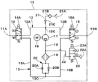
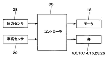
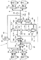
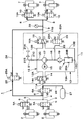
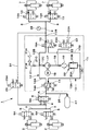
- FIG. 1 is a circuit diagram showing an overall configuration of an air suspension system according to a first embodiment. It is a circuit diagram which shows the structure of the compression apparatus in FIG. It is a block diagram which shows the control apparatus of the air suspension system by 1st Embodiment. It is a circuit diagram showing the flow of compressed air when raising the vehicle height on the front wheel side and the vehicle height on the rear wheel side simultaneously. It is a circuit diagram showing the flow of compressed air when raising the vehicle height on the rear wheel side without using a compression device. It is a circuit diagram showing the flow of compressed air when lowering the vehicle height on the front wheel side. It is a circuit diagram showing the flow of compressed air when lowering the vehicle height on the rear wheel side.
- FIG. 1 to FIG. 7 show a first embodiment of the present invention.
- a vehicle-mounted air suspension system 1 includes a front wheel side air suspension 2, a rear wheel side air suspension 7, a compression device 11, a tank 27, and a controller 30.
- the front wheel side air suspension 2 is located on the front wheel side of the vehicle, and is provided between the vehicle body side and the axle side (both not shown) of the vehicle. Specifically, two front wheel side air suspensions 2 are provided so as to correspond to the front left and right wheels, respectively. When the compressed air is supplied or discharged, the front wheel side air suspension 2 adjusts the vehicle height by expanding or contracting upward or downward according to the supply / discharge amount (compressed air amount) of the air at this time. It is.
- the front wheel side air suspension 2 is connected to the tank 27 via the front branch pipe 3 and the front supply / discharge path 4.
- one end of the front branch pipe 3 is connected to the left and right front wheel side air suspensions 2, and the other end of the front branch pipe 3 is connected to the front supply / discharge path 4.
- a front air supply / exhaust valve 5 is provided in the middle of the front branch pipe 3.
- one end of the front supply / discharge path 4 is connected to the front branch pipe 3, and the other end of the front supply / discharge path 4 is connected to a front connection point 11 ⁇ / b> A of the compression device 11 described later.
- a front switching valve 6 is provided in the middle of the front supply / discharge path 4.
- the front air supply / exhaust valve 5 is located between the front wheel side air suspension 2 and the front switching valve 6 and is provided in each front branch pipe 3.
- the front air supply / exhaust valve 5 is constituted by a 2-port 2-position electromagnetic valve having a solenoid (coil) 5A, and is switched and controlled by a controller 30 described later.
- the front side air supply / exhaust valve 5 is opened from the controller 30 by supplying power to the solenoid 5A, thereby opening each front side branch line 3 to allow compressed air to be supplied to and discharged from the front wheel side air suspension 2, and each front side
- the branch line 3 is closed and selectively switched to a closed position (b) where the supply and discharge of compressed air to the front wheel side air suspension 2 is blocked.
- the front side air supply / exhaust valve 5 constitutes a front wheel side switching portion that switches the communication state between the front wheel side air suspension 2 and the tank 27.
- the front switching valve 6 is located between the front air supply / exhaust valve 5 and the compressor 11 and is provided in the front air supply / discharge path 4.
- the front side switching valve 6 is constituted by a 2-port 2-position electromagnetic valve provided with a solenoid 6A, and is switched and controlled by a controller 30 described later.
- the front side switching valve 6 is opened by the power supply from the controller 30 to the solenoid 6 ⁇ / b> A, thereby opening the front side supply / discharge path 4 and allowing the compressed air to be supplied / discharged to / from the front wheel side air suspension 2.
- 4 is selectively switched to a closed position (d) where the supply and discharge of compressed air to the front wheel side air suspension 2 is shut off.
- the front side switching valve 6 and the front side air supply / exhaust valve 5 constitute a front wheel side switching unit that switches the communication state between the front wheel side air suspension 2 and the tank 27.
- the rear wheel side air suspension 7 is located on the rear wheel side of the vehicle, and is retrofitted between the vehicle body side and the axle side (both not shown) of the vehicle. Specifically, two rear wheel side air suspensions 7 are provided so as to correspond to the rear left and right wheels, respectively. When compressed air is supplied or discharged, the rear wheel side air suspension 7 expands or contracts upward or downward according to the supply / discharge amount (compressed air amount) of the air at this time to adjust the vehicle height. Is.
- the rear wheel side air suspension 7 is connected to a tank 27 via a rear branch pipe 8, a rear supply / discharge path 9 and a compression device 11 described later.
- one end of the rear branch conduit 8 is connected to the rear supply / discharge passage 9, and the other end of the rear branch conduit 8 is connected to the rear wheel side air suspension 7.
- a rear air supply / exhaust valve 10 is provided in the middle of the rear branch pipe 8.
- one end of the rear supply / discharge path 9 is connected to a rear connection point 11B of the compression device 11 described later, and the other end of the rear supply / discharge path 9 is connected to the rear branch pipe line 8.
- a pressure sensor 28 described later is connected in the middle of the rear supply / discharge path 9.
- the rear side air supply / exhaust valve 10 is located between the rear wheel side air suspension 7 and the compression device 11, and is provided in each rear side branch pipe 8.
- the rear side air supply / exhaust valve 10 is constituted by a 2-port 2-position electromagnetic valve provided with a solenoid 10 ⁇ / b> A, and is switched and controlled by the controller 30.
- the rear side air supply / exhaust valve 10 is supplied with power from the controller 30 to the solenoid 10 ⁇ / b> A, thereby opening each rear side branch pipe 8 and allowing the rear wheel side air suspension 7 to supply and discharge compressed air.
- each rear branch pipe line 8 is closed and selectively switched to a closed position (f) where the supply / discharge of compressed air to / from the rear wheel side air suspension 7 is shut off.
- the rear side air supply / exhaust valve 10 constitutes a rear wheel side switching unit that switches the communication state between the rear wheel side air suspension 7 and the compression device 11.
- the compression device 11 is connected between the front wheel side air suspension 2 and the rear wheel side air suspension 7. Specifically, one end of the compression device 11 is connected to the front supply / discharge path 4 via the front connection point 11A, and the other end of the compression device 11 is connected to the rear supply / discharge path 9 via the rear connection point 11B.
- the compression device 11 includes first and second ventilation pipes 12 and 13, first and second switching valves 14 and 15, a main pipe 16, a compressor 17, an electric motor 18, an air dryer 19, It includes a speed control valve 20, a suction pipe 21, an exhaust pipe 22, and the like.
- the compressor 11 serves as a compressed air source for supplying compressed air to the front wheel side air suspension 2 and the rear wheel side air suspension 7.
- the first ventilation pipe 12 connects the front supply / discharge path 4 via the front connection point 11A, and the other end of the first ventilation pipe 12 is connected to the rear supply / discharge path 9 via the rear connection point 11B. It is connected.
- the first vent pipe 12 connects the front supply / discharge path 4 and the rear supply / discharge path 9 across the suction side of the compressor 17.
- the first vent pipe 12 is connected to the front first vent pipe 12A that connects between the front connection point 11A and a connection point 12C of the main pipe 16, which will be described later, and the connection point 12C and the rear connection of the main pipe 16. It is comprised from the back side 1st ventilation pipe line 12B which connects between the points 11B.
- a first switching valve 14 to be described later is provided in the front first ventilation duct 12A.
- the front first ventilation duct 12 ⁇ / b> A constitutes a ventilation path that guides the compressed air in the tank 27 to the suction side of the compressor 17 when the rear wheel side air suspension 7 and the compressor 17 communicate with each other.
- a second switching valve 15 described later is provided in the rear first ventilation duct 12B.
- the second ventilation conduit 13 connects the first switching valve 14 and the second switching valve 15 across the discharge side of the compressor 17.
- the second vent line 13 includes a front second vent line 13A that connects the first switching valve 14 and the connection point 13C of the main line 16, and a connection point 13C of the main line 16 and the second switching valve. 15, a rear second ventilation duct 13 ⁇ / b> B connecting between the two.
- the first switching valve 14 is located between the front switching valve 6 and the suction side of the compressor 17 and is provided on one end side of the front first ventilation duct 12A.
- the first switching valve 14 selectively connects the front supply / exhaust passage 4 to the suction side (first ventilation conduit 12) or the discharge side (second ventilation conduit 13) of the compressor 17, for example, a solenoid It is constituted by a three-port, two-position electromagnetic direction switching valve provided with 14A, and is switched and controlled by the controller 30.
- the first switching valve 14 supplies and discharges the compressed air in the tank 27 to the rear wheel side air suspension 7 through the front first ventilation duct 12A and the main duct 16 by supplying power from the controller 30 to the solenoid 14A.
- the supply position (g) for supplying the compressed air in the air suspensions 2, 7 to the supply position (h) for supplying (sending) the compressed air in the air suspensions 2 and 7 into the tank 27 through the main pipe line 16 and the front second ventilation pipe line 13A Switched. That is, the 1st switching valve 14 comprises the switching mechanism which changes the flow direction of compressed air.
- the second switching valve 15 is located between the rear side air supply / exhaust valve 10 and the suction side of the compressor 17 and is provided on the other end side of the rear side first ventilation pipe 12B.
- the second switching valve 15 is, for example, a three-port two-position electromagnetic valve having a solenoid 15A. It consists of a direction switching valve and is controlled to be switched by the controller 30.
- the second switching valve 15 is supplied with electric power from the controller 30 to the solenoid 15A, so that the compressed air in the tank 27 passes through the front first vent line 12A, the main pipe line 16, and the rear second vent line 13B.
- Supply position (i) for supplying / discharging to / from the rear wheel side air suspension 7 and the compressed air in the air suspensions 2 and 7 are tanked through the rear first ventilation duct 12B, the main duct 16, and the front second ventilation duct 13A.
- 27 is selectively switched to a delivery position (j) to be supplied (sent out) in 27. That is, the second switching valve 15 constitutes a rear wheel side switching unit that changes the flow direction of the compressed air to switch the communication state between the rear wheel side air suspension 7 and the compression device 11.
- the main pipeline 16 connects between the first ventilation pipeline 12 and the second ventilation pipeline 13. That is, one end on the upstream side of the main pipeline 16 is connected to a connection point 12C of the first ventilation pipeline 12 (between the front first ventilation pipeline 12A and the rear first ventilation pipeline 12B). The other end on the downstream side is connected to a connection point 13C (between the front second vent pipe 13A and the rear second vent pipe 13B) of the second vent pipe 13.
- the main pipe line 16 constitutes a supply / exhaust pipe line that supplies / discharges compressed air to / from the air suspensions 2, 7.
- the main pipeline 16 is provided with a compressor 17, an air dryer 19, and a speed control valve 20.
- the compressor 17 is located in the main pipeline 16 and is constituted by, for example, a reciprocating compressor or a scroll compressor.
- the compressor 17 is driven by an electric motor 18 as a drive source, compresses air sucked from the first ventilation pipe line 12 side or the suction pipe line 21 side to generate compressed air, and sends the compressed air to the air dryer 19. Supply towards.
- the air dryer 19 is located in the main pipeline 16 and is provided between the compressor 17 and the speed control valve 20.
- the air dryer 19 contains a moisture adsorbent (not shown) and the like, and when compressed air supplied from the compressor 17 flows in the forward direction toward the speed control valve 20, moisture is absorbed by the internal moisture adsorbent. Adsorb.
- the air dryer 19 supplies dry compressed air (dry air) toward the air suspensions 2 and 7.
- the compressed air (exhaust gas) flowing in the reverse direction from the air suspensions 2, 7 or the tank 27 toward the exhaust pipe 22 described later flows back in the air dryer 19, thereby moisture adsorbed by the moisture adsorbent.
- the moisture adsorbent is regenerated.
- the speed control valve 20 is located in the main pipeline 16 and is provided between the air dryer 19 and the second ventilation pipeline 13.
- the speed control valve 20 is configured by a parallel circuit of a throttle 20A and a check valve 20B, and the check valve 20B is not opened and the flow rate of the compressed air is not throttled for forward flow.
- the check valve 20B closes against the flow in the reverse direction, and the flow rate of the compressed air at this time is throttled by the throttle 20A, so that the air dryer 19 slowly reverses with a small flow rate.
- the suction pipe 21 is provided upstream of the compressor 17 on the suction side. Specifically, one end of the suction pipe 21 communicates with the outside via the suction port 21 ⁇ / b> A, and the other end of the suction pipe 21 is connected to the first ventilation pipe 12.
- the suction pipe 21 supplies the outside air or the air sucked from the suction port 21A toward the compressor 17 through the filter 21B when the compressor 17 is operated.
- the suction pipe 21 is provided with a check valve 21C that prevents the backflow of air sucked from the suction port 21A.
- the exhaust pipe line 22 is provided between the discharge side of the compressor 17 and the speed control valve 20. Specifically, one end of the exhaust pipeline 22 is connected to the main pipeline 16, and the other end of the exhaust pipeline 22 communicates with the outside through the exhaust port 22A.
- the exhaust pipe 22 is a pipe for discharging the compressed air in the air suspensions 2 and 7 and the tank 27 to the outside atmosphere.
- An exhaust valve 23 is provided in the middle of the exhaust pipe line 22.
- the exhaust valve 23 is a valve that allows the exhaust pipe line 22 connected to the main pipe line 16 to communicate with the atmosphere and shut off.
- the exhaust valve 23 is configured by a 2-port 2-position electromagnetic valve having a solenoid 23 ⁇ / b> A, and is switched and controlled by the controller 30.
- the exhaust valve 23 is supplied with power from the controller 30 to the solenoid 23A, thereby opening the exhaust line 22 and allowing the compressed air to be discharged from the exhaust port 22A. It is selectively switched to the closed position (l) that blocks the discharge of compressed air from the port 22A. That is, the exhaust valve 23 is normally closed to block the exhaust pipe 22 from the exhaust port 22A.
- the exhaust conduit 22 When the exhaust valve 23 is opened, the exhaust conduit 22 is communicated with the exhaust port 22A, and the compressed air in the exhaust conduit 22 is discharged (released) into the atmosphere.
- the bypass conduit 24 is provided across the compression device 11. Specifically, one end of the bypass pipe 24 is connected to the front supply / discharge path 4, and the other end of the bypass pipe 24 is connected to the rear supply / discharge path 9.
- the bypass pipe 24 bypasses the compressor 11 and sends compressed air from the front supply / discharge path 4 to the rear supply / discharge path 9 or from the rear supply / discharge path 9 to the front supply / discharge path 4. is there.
- a bypass valve 25 is provided in the middle of the bypass conduit 24.
- the bypass valve 25 is a valve that allows the bypass pipeline 24 to communicate and shut off.
- the bypass valve 25 is constituted by a 2-port 2-position electromagnetic valve having a solenoid 25 ⁇ / b> A, and is switched and controlled by the controller 30.
- the bypass valve 25 is supplied with power from the controller 30 to the solenoid 25 ⁇ / b> A, thereby opening the bypass line 24 and communicating between the front supply / discharge path 4 and the rear supply / discharge path 9, It is selectively switched to a closed position (n) where the conduit 24 is closed and the front supply / discharge path 4 and the rear supply / discharge path 9 are blocked.
- the tank conduit 26 is located between the front switching valve 6 and the first switching valve 14 and is provided in the middle of the front supply / discharge passage 4. Specifically, one end of the tank conduit 26 is connected to the front supply / discharge passage 4, and the other end of the tank conduit 26 is connected to the tank 27.
- the tank 27 stores (stores) compressed air pressurized by the compressor 17 to exceed atmospheric pressure.
- the tank 27 and the compressor 17 are connected to each other via the front supply / discharge passage 4, the front first ventilation conduit 12 ⁇ / b> A, the front second ventilation conduit 13 ⁇ / b> A, the main conduit 16, and the tank conduit 26.
- the compressed air supplied from the compressor 17 is stored in the tank 27 through the main conduit 16, the front second vent conduit 13A, the front first vent conduit 12A, the front supply / exhaust passage 4, the tank conduit 26, and the like. It is done.
- the compressed air stored in the tank 27 is supplied to the front wheel air suspension 2 through the front supply / discharge passage 4 and the front branch conduit 3, and the rear wheel through the rear supply / discharge passage 9 and the rear branch conduit 8.
- the air suspension 7 is supplied.
- the pressure sensor 28 is located between the rear supply / exhaust valve 10 and the second switching valve 15 and is provided in the middle of the rear supply / discharge path 9.
- the pressure sensor 28 detects the pressure of the compressed air in the air suspensions 2 and 7 and the tank 27 by detecting the pressure in the rear supply / discharge passage 9.
- Each of the air suspensions 2 and 7 is provided with a vehicle height sensor 29 as a vehicle height detector (see FIG. 3).
- the vehicle height sensor 29 detects a displacement in the direction in which the air suspensions 2 and 7 expand or contract (displacement in the vertical direction), and outputs a detection signal to the controller 30 described later.
- the controller 30 is configured by a microcomputer or the like as a control device that controls supply and discharge of compressed air to and from the air suspensions 2 and 7. As shown in FIG. 3, the input side of the controller 30 is connected to the pressure sensor 28, the vehicle height sensor 29, and the like, and the output side of the controller 30 is the electric motor 18, each valve 5, 6, 10, 14, 15, 23, 25 are connected to solenoids 5A, 6A, 10A, 14A, 15A, 23A, 25A and the like.
- the controller 30 controls driving and stopping of the electric motor 18 and controls opening and closing of the valves 5, 6, 10, 14, 15, 23, and 25. That is, the controller 30 controls the air suspensions 2 and 7 as the vehicle height adjusting mechanism by controlling the valves 5, 6, 10, 14, 15, 23, and 25 to control the vehicle height before and after the vehicle. adjust.
- the controller 30 controls driving and stopping of the electric motor 18 based on detection signals input from the pressure sensor 28, the vehicle height sensor 29, and the like, and changes the duty ratio of the PWM signal, for example, by changing the duty ratio of the PWM signal.
- the current supplied to 6, 10, 14, 15, 23, 25 is controlled.
- the air suspension system 1 has the above-described configuration, and the operation thereof will be described next.
- the first switching valve 14 is sent from the supply position (g).
- the position is switched to the position (h), and the front switching valve 6, the rear supply / exhaust valve 10, the exhaust valve 23, and the bypass valve 25 are held at the closed positions (d), (f), (l), and (n).
- the electric motor 18 operates the compressor 17 (that is, compression operation).
- the compressor 17 sucks outside air into the compressor 17 through the suction port 21A of the suction pipe 21, the filter 21B, the check valve 21C and the main pipe 16, pressurizes (compresses) the air, and compresses the compressed air into the air dryer 19. Discharge toward The compressed air discharged from the compressor 17 is dried by the air dryer 19 and then passes through the speed control valve 20, the front second ventilation pipe 13 ⁇ / b> A, the front first ventilation pipe 12 ⁇ / b> A, the front supply / discharge path 4, and the tank pipe 26. And stored in the tank 27. For example, when the pressure in the tank 27 reaches a predetermined set pressure, the compressor 17 is stopped. Thereby, the tank 27 can be filled with a sufficient amount of compressed air and stored.
- the compressed air in the tank 27 is boosted by the compressor 17, and the compressed air is supplied to the main pipeline 16, the rear second ventilation pipeline 13 ⁇ / b> B, the rear first ventilation pipeline 12 ⁇ / b> B, the rear supply / exhaust passage 9, It is supplied toward the rear wheel side air suspension 7 through the rear branch pipe line 8.
- the compressor 17 divides the compressed air from the tank 27 toward the front wheel side air suspension 2 and the compressed air from the tank 27 toward the rear wheel side air suspension 7.
- the pressure of the compressed air toward the front wheel side air suspension 2 and the pressure of the compressed air toward the rear wheel side air suspension 7 are made different from each other, so that the pressure in the front wheel side air suspension 2 and the pressure in the rear wheel side air suspension 7 are changed.
- Pressure is prevented from affecting each other. That is, since the compressed air going to the rear wheel side air suspension 7 passes through the compressor 17, the pressure becomes higher than the compressed air going to the front wheel side air suspension 2.
- the pressure of the compressed air in the tank 27 is set to a sufficient level in advance so that the compressor 17 does not suck air from the front wheel side air suspension 2. It is good to set.
- the front supply / exhaust valve 5 and the front switching valve 6 are switched to the open positions (a), (c), and the rear supply / exhaust
- the valve 10 and the bypass valve 25 are held in the closed positions (f) and (n).
- the compressed air in the tank 27 can be supplied only to the front wheel side air suspension 2 via the front side supply / discharge passage 4 and the front side branch conduit 3.
- the front side air supply / exhaust valve 5 and the rear side air supply / exhaust valve 10 are switched to the closed positions (b) and (f), and the front side branch line 3 and the rear side branch line 8 are connected. Close each one. As a result, the flow of compressed air to the air suspensions 2 and 7 can be blocked, and the air suspensions 2 and 7 can be kept in the extended state and the vehicle height can be kept high.
- the front air supply / exhaust valve 5 and the bypass valve 25 are switched to the open positions (a) and (m), and the front side switching valve 6 and the rear
- the side air supply / exhaust valve 10 is held in the closed positions (d) and (f).
- the first switching valve 14 and the second switching valve 15 are switched from the supply position (g), (i) to the delivery position (h), (j).
- the compressor 17 pressurizes the compressed air in the front wheel side air suspension 2, and the compressed air is supplied to the main pipeline 16, the front second ventilation pipeline 13A, the front first ventilation pipeline 12A, the front supply / exhaust passage 4, Supply to the tank 27 through the tank line 26.
- the compressed air is discharged from the front wheel side air suspension 2 and the front wheel side air suspension 2 shifts to the contracted state, whereby the vehicle height can be lowered.
- the compressor 17 pressurizes the compressed air in the rear wheel side air suspension 7, and the compressed air is supplied to the main pipeline 16, the front second ventilation conduit 13 ⁇ / b> A, the front first ventilation conduit 12 ⁇ / b> A, and the front supply / exhaust passage 4. Then, it is supplied to the tank 27 through the tank conduit 26. As a result, the compressed air is discharged from the rear wheel side air suspension 7 and the rear wheel side air suspension 7 shifts to the contracted state, whereby the vehicle height can be lowered.
- the front side switching valve 6, the rear side air supply / exhaust valve 10, and the bypass valve 25 are held at the closed positions (d), (f), (n),
- the exhaust valve 23 is switched to the open position (k).
- the first switching valve 14 is held at the delivery position (h).
- the compressed air in the tank 27 is supplied to the tank pipe 26, the front supply / discharge path 4, the front first ventilation pipe 12A, the front second ventilation pipe 13A, the main pipe 16, and the throttle 20A of the speed control valve 20.
- the air can be discharged directly from the exhaust port 22 ⁇ / b> A via the air dryer 19 and the exhaust pipe line 22.
- the compressed air discharged from the tank 27 flows to the exhaust pipe line 22 through the air dryer 19, the moisture can be removed from the desiccant filled in the air dryer 19, and the desiccant is regenerated. .
- the compressed air in the tank 27 is supplied to the front wheel side air suspension 2, and the rear
- the wheel-side air suspension 7 is configured so that the compressed air in the tank 27 is pressurized and supplied by the compressor 17.
- the vehicle front wheel side and the vehicle rear wheel side can be raised simultaneously by one tank 27.
- the number of tanks 27 can be minimized, so that the vehicle mounting space and the vehicle weight can be reduced, and the number of parts such as tank valves and pressure sensors can be reduced.
- the vehicle front wheel side and the vehicle rear wheel side may be raised separately.
- the compressed air in the tank 27 and the compressed air pressurized by the compressor 17 can be supplied to the air suspensions 2 and 7, respectively, the vehicle height on the front wheel side and the vehicle height on the rear wheel side can be adjusted. Can be raised at the same time. As a result, the rising time can be shortened as compared with the case where the vehicle height on the front wheel side and the vehicle height on the rear wheel side are increased one side at a time.
- the compressor 17 is used to divide the compressed air from the tank 27 toward the front wheel side air suspension 2 and the compressed air from the tank 27 toward the rear wheel side air suspension 7.
- the pressure of the compressed air toward the front wheel side air suspension 2 and the pressure of the compressed air toward the rear wheel side air suspension 7 are made different from each other, so that the pressure in the front wheel side air suspension 2 and the pressure in the rear wheel side air suspension 7 are changed. Pressure can be prevented from affecting.
- the compressor 17 is used to divide the compressed air from the tank 27 toward the front wheel side air suspension 2 and the compressed air from the tank 27 toward the rear wheel side air suspension 7.
- the behavior of the vehicle when the vehicle height rises can be stabilized.
- the inclination when the vehicle is raised can be reduced, the angle of the headlight during traveling of the vehicle is hardly changed, and at the same time, the vehicle appearance performance can be improved.
- the compressed air in the tank 27 is supplied to the front wheel side air suspension 2, and the compressed air in the tank 27 is boosted to the rear wheel side air suspension 7 by the compressor 17. It is set as the structure supplied. Thereby, the pressure of the compressed air supplied to the rear wheel side air suspension 7 can be made higher than the pressure of the compressed air supplied to the front wheel side air suspension 2.
- the air suspension system 1 stores the compressed air compressed by the compressor 17 in the tank 27 and can supply the compressed air stored in the tank 27 to the air suspensions 2 and 7 (closed system). ). As a result, the air suspension system 1 is less susceptible to external temperature, humidity, pressure, etc., and can perform stable suspension control.
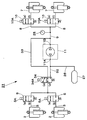
- FIG. 8 shows a second embodiment of the present invention.
- the feature of the second embodiment resides in that the front switching valve is connected to the front supply / discharge passage and the bypass conduit.
- the same components as those in the first embodiment are denoted by the same reference numerals, and the description thereof is omitted.
- an in-vehicle air suspension system 31 is similar to the air suspension system 1 of the first embodiment in that a front wheel side air suspension 2, a rear wheel side air suspension 7, a compression device 11, a tank 27, and a controller 30. It is comprised including.
- the air suspension system 31 of the second embodiment is different from that of the first embodiment in that a front switching valve 34 described later is connected to the front branch pipe 3, the front supply / discharge path 32, and the bypass pipe 33. This is different from the air suspension system 1 in the form.
- the front supply / discharge path 32 is provided between the compressor 11 and the front switching valve 34. Specifically, one end of the front supply / discharge path 32 is connected to the front switching valve 34, and the other end of the front supply / discharge path 32 is connected to the front connection point 11 ⁇ / b> A of the compressor 11. In the middle of the front supply / discharge path 32, a tank pipe line 26 is connected.
- the bypass conduit 33 is provided across the compression device 11. Specifically, one end of the bypass conduit 33 is connected to the front branch conduit 3, and the other end of the bypass conduit 33 is connected to the rear supply / exhaust passage 9.
- the bypass pipe 33 bypasses the compressor 11 and sends compressed air from the front branch pipe 3 to the rear supply / discharge path 9 or from the rear supply / discharge path 9 to the front branch pipe 3. is there.
- a front side switching valve 34 is provided in the middle of the bypass line 33.
- the front switching valve 34 is located between the front air supply / exhaust valve 5 and the compressor 11 and is provided in the bypass line 33.
- the front side switching valve 34 selectively connects the other end of the bypass pipe 33 to the front side supply / discharge path 32 or the rear side supply / exhaust path 9, for example. It consists of a direction switching valve and is controlled to be switched by the controller 30.
- the front side switching valve 34 is supplied with electric power from the controller 30 to the solenoid 34 ⁇ / b> A, so that the compressed air in the tank 27 passes through the front supply / discharge passage 32, the bypass conduit 33, and the front branch conduit 3.
- the supply position (o) for supplying and discharging to the tank and the compressed air in the front wheel side air suspension 2 are tanked through the front branch pipe 3, the rear supply / discharge path 9, the compressor 11, the front supply / discharge path 32, and the tank pipe 26. 27 is selectively switched to a delivery position (p) to be supplied (delivered) in 27.
- the front switching valve 34 constitutes a front wheel switching unit that switches the communication state between the front wheel air suspension 2 and the tank 27.
- the front wheel side switching unit that switches the communication state between the front wheel side air suspension 2 and the tank 27 is configured using the front side switching valve 34 at the 3 port 2 position. Thereby, it is possible to communicate and block between the front wheel side air suspension 2 and the tank 27 or between the front wheel side air suspension 2 and the rear supply / discharge path 9 by using one front side switching valve 34. As a result, there is no need to provide electromagnetic valves in the front supply / exhaust passage 32 and the bypass conduit 33, respectively, and the number of electromagnetic valves can be reduced, so that component costs can be suppressed.
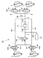
- FIG. 9 shows a third embodiment of the present invention.
- a feature of the third embodiment resides in that the front air supply / exhaust valve is connected to the front branch pipe and the bypass pipe. Note that in the third embodiment, the same components as those in the first embodiment described above are denoted by the same reference numerals, and description thereof is omitted.
- an in-vehicle air suspension system 41 is similar to the air suspension system 1 of the first embodiment in that a front wheel side air suspension 2, a rear wheel side air suspension 7, a compression device 11, a tank 27, and a controller 30. It is comprised including.
- the air suspension system 41 of the third embodiment is similar to the air suspension system of the first embodiment in that a front air supply / exhaust valve 43 (to be described later) is connected to a front branch pipe 42 and a bypass pipe 44. 1 and different.
- the front branch pipe 42 is provided between the front wheel side air suspension 2 and the front supply / discharge path 4. Specifically, one end of the front branch pipe 42 is connected to the left and right front wheel side air suspensions 2, and the other end of the front branch pipe 42 is connected to the front supply / discharge path 4.
- a front air supply / exhaust valve 43 is provided in the middle of each front branch pipe 42.
- the front side air supply / exhaust valve 43 is located between the front wheel side air suspension 2 and the front side switching valve 6 and is provided in each front side branch pipe 42.
- the front side air supply / exhaust valve 43 selectively connects the other end of the front side branch pipeline 42 to the front side supply / exhaust passage 4 or the bypass pipeline 44. It consists of a direction switching valve and is controlled to be switched by the controller 30.
- the front side air supply / exhaust valve 43 supplies and discharges the compressed air in the tank 27 to the front wheel side air suspension 2 through the front side supply / exhaust passage 4 and the front side branch conduit 42 by supplying power to the solenoid 43A from the controller 30.
- the supply position (q) and the compressed air in the front wheel side air suspension 2 are passed through the front branch pipe 42, the bypass pipe 44, the rear supply / discharge path 9, the compressor 11, the front supply / discharge path 4, and the tank pipe 26.
- the position is selectively switched to a delivery position (r) to be supplied (sent out) into the tank 27.
- the front side air supply / exhaust valve 43 constitutes a front wheel side switching unit that switches the communication state between the front wheel side air suspension 2 and the tank 27.
- Each bypass pipe 44 is connected to the left and right front branch pipes 42, and the other end of each bypass pipe 44 is connected to the rear supply / discharge path 9. These bypass conduits 44 bypass the compressor 11 and send compressed air from the front branch conduit 42 to the rear supply / exhaust passage 9 or from the rear supply / exhaust passage 9 to the front branch conduit 42. It is.
- the front wheel side switching unit that switches the communication state between the front wheel side air suspension 2 and the tank 27 is configured using the front air supply / exhaust valve 43 at the 3 port 2 position.
- the front wheel side air suspension 2 and the tank 27 is communicate and block between the front wheel side air suspension 2 and the tank 27 or between the front wheel side air suspension 2 and the rear side supply / exhaust passage 9 by using one front side air supply / exhaust valve 43.
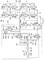
- FIG. 10 shows a fourth embodiment of the present invention.
- the feature of the fourth embodiment is that the circuit configuration of the compression device is different from the circuit configuration of the compression device of the first embodiment. Note that in the fourth embodiment, the same components as those in the first embodiment described above are denoted by the same reference numerals, and description thereof is omitted.
- an in-vehicle air suspension system 51 includes a front wheel side air suspension 2, a rear wheel side air suspension 7, a compression device 52, a tank 27, and a controller 30, similarly to the air suspension system 1 of the first embodiment. It is comprised including.
- the air suspension system 51 of the fourth embodiment is the same as the air suspension system 51 of the first embodiment in that the circuit configuration of the compression device 52 is changed to the circuit configuration of the compression device 11 of the first embodiment. Different from the suspension system 1.
- the compression device 52 is connected between the front wheel side air suspension 2 and the rear wheel side air suspension 7. Specifically, one end of the compression device 52 is connected to the front supply / discharge path 4 via the front connection point 52A, and the other end of the compression device 52 is connected to the rear supply / discharge path 9 via the rear connection point 52B.
- the compression device 52 includes a ventilation pipe 53, a main pipe 54, a supply / discharge passage 55, first and second switching valves 56 and 57, a compressor 58, an electric motor 59, an air dryer 60, and speed control.
- a valve 61, a suction pipe 62, an exhaust pipe 63, and the like are included.
- the compression device 52 forms a compressed air source for supplying compressed air to the front wheel side air suspension 2 and the rear wheel side air suspension 7.
- vent pipe 53 One end of the vent pipe 53 is connected to the front supply / discharge path 4 via the front connection point 52A, and the other end of the vent pipe 53 is connected to the rear supply / discharge path 9 via the rear connection point 52B.
- the ventilation duct 53 extends between the suction side of the compressor 58 and connects the front supply / discharge path 4 and the rear supply / discharge path 9.
- the vent line 53 includes a front vent line 53A that connects the front connection point 52A and a connection point 53C of the main pipe 54 described later, and a connection point 53C and a rear connection point 52B of the main pipe 54. It is comprised from the back side ventilation pipe line 53B which connects between.
- a first switching valve 56 which will be described later, is provided in the front side vent line 53A.
- the front vent line 53A constitutes a vent path that guides the compressed air in the tank 27 to the suction side of the compressor 58 when the rear wheel side air suspension 7 and the compressor 58 communicate with each other.
- the rear vent pipe 53B is provided with a second switching valve 57 which will be described later.
- the main pipeline 54 connects between the ventilation pipeline 53 and the first switching valve 56. That is, one end on the upstream side of the main conduit 54 is connected to a connection point 53C (between the front vent conduit 53A and the rear vent conduit 53B) of the vent conduit 53, and the other end on the downstream side of the main conduit 54 is The first switching valve 56 is connected.
- the main pipeline 54 constitutes a supply / exhaust pipeline that supplies and discharges compressed air to and from the air suspensions 2 and 7.
- the main pipeline 54 is provided with a compressor 58, an air dryer 60, and a speed control valve 61.
- the supply / discharge passage 55 is provided between the main pipeline 54 and the second switching valve 57. Specifically, one end of the supply / discharge passage 55 is connected to the main pipeline 54, and the other end of the supply / discharge passage 55 is connected to the second switching valve 57.
- the supply / discharge passage 55 connects between the discharge side of the compressor 58 and the second switching valve 57.
- the first switching valve 56 is located between the front switching valve 6 and the suction side of the compressor 58, and is provided on one end side of the front vent line 53A.
- the first switching valve 56 includes a solenoid 56 ⁇ / b> A for selectively connecting the front supply / discharge passage 4 to the suction side (venting conduit 53) or the discharging side (main conduit 54) of the compressor 58. It is composed of an electromagnetic direction switching valve at the port 2 position, and is switched and controlled by the controller 30.
- the first switching valve 56 is supplied with electric power from the controller 30 to the solenoid 56 ⁇ / b> A, so that the compressed air in the tank 27 passes through the front-side ventilation line 53 ⁇ / b> A, the main line 54, and the supply / discharge path 55.
- the second switching valve 57 is located between the rear side air supply / exhaust valve 10 and the suction side of the compressor 58, and is provided on the other end side of the rear side vent line 53B.
- the second switching valve 57 is, for example, a three-port two-position electromagnetic direction switching valve provided with a solenoid 57A in order to selectively connect the ventilation pipe 53 or the supply / discharge passage 55 to the rear supply / discharge passage 9. It is configured and controlled to be switched by the controller 30.
- the second switching valve 57 is supplied with electric power from the controller 30 to the solenoid 57 ⁇ / b> A, so that the compressed air in the tank 27 passes through the front-side vent line 53 ⁇ / b> A, the main line 54, and the supply / discharge path 55.
- the compressor 58 is located in the main pipeline 54 and is constituted by, for example, a reciprocating compressor or a scroll compressor.
- the compressor 58 is driven by an electric motor 59 as a drive source, compresses air sucked from the vent pipe 53 side or the suction pipe 62 side, generates compressed air, and directs the compressed air toward the air dryer 60. Supply.
- the air dryer 60 is located in the main pipeline 54 and is provided between the compressor 58 and the speed control valve 61.
- the air dryer 60 contains a moisture adsorbent and the like, and adsorbs moisture with the internal moisture adsorbent when the compressed air supplied from the compressor 58 flows in the forward direction toward the speed control valve 61.
- the compressed air flowing in the reverse direction from the air suspensions 2 and 7 or the tank 27 toward the exhaust pipe 63 described later takes the moisture adsorbed by the moisture adsorbent by flowing back in the air dryer 60, This moisture adsorbent is regenerated.
- the speed control valve 61 is located in the main pipeline 54 and is provided between the air dryer 60 and the first switching valve 56.
- the speed control valve 61 is configured by a parallel circuit of a throttle 61A and a check valve 61B.
- the check valve 61B is not opened and the flow rate of the compressed air is not throttled.
- the check valve 61B closes against the flow in the reverse direction, and the flow rate of the compressed air at this time is throttled by the throttle 61A, so that the air flows in the air dryer 60 slowly at a small flow rate.
- the suction pipe 62 is provided upstream of the compressor 58 on the suction side. Specifically, one end of the suction pipe 62 communicates with the outside via the suction port 62 ⁇ / b> A, and the other end of the suction pipe 62 is connected to the vent pipe 53.
- the suction pipe 62 supplies the outside air or the air sucked from the suction port 62A toward the compressor 58 through the filter 62B when the compressor 58 is operated.
- the suction pipe line 62 is provided with a check valve 62C that prevents the backflow of air sucked from the suction port 62A.
- the exhaust pipe 63 is provided between the rear connection point 52 ⁇ / b> B and the second switching valve 57. Specifically, one end of the exhaust pipe line 63 is connected to the rear side vent pipe line 53B, and the other end of the exhaust pipe line 63 communicates with the outside through the exhaust port 63A.
- the exhaust pipe 63 is a pipe for discharging the compressed air in the air suspensions 2 and 7 and the tank 27 to the outside atmosphere.
- An exhaust valve 64 is provided in the middle of the exhaust pipe line 63.
- the exhaust valve 64 is a valve that communicates and blocks the exhaust pipe 63 connected to the main pipe 54 to the atmosphere.
- the exhaust valve 64 is constituted by a 2-port 2-position electromagnetic valve having a solenoid 64 ⁇ / b> A, and is switched and controlled by the controller 30.
- the exhaust valve 64 is supplied with electric power from the controller 30 to the solenoid 64A, thereby opening the exhaust pipe 63 and allowing the compressed air to be discharged from the exhaust port 63A, and closing the exhaust pipe 63 to exhaust the exhaust valve 64. It is selectively switched to the closed position (x) that blocks the discharge of compressed air from the port 63A. That is, the exhaust valve 64 is normally closed to block the exhaust pipe 63 from the exhaust port 63A.
- the exhaust valve 64 is opened, the exhaust pipe 63 is communicated with the exhaust port 63A, and the compressed air in the exhaust pipe 63 is discharged (released) into the atmosphere.
- the first switching valve 56 is connected to the front vent line 53 ⁇ / b> A and the main line 54.
- the second switching valve 57 is connected to the rear side vent pipe 53 ⁇ / b> B and the supply / discharge passage 55.
- the vehicle front wheel side and the vehicle rear wheel side can be raised simultaneously by one tank 27.
- the vehicle front wheel side and the vehicle rear wheel side may be raised separately.
- the number of tanks 27 can be minimized, so that the vehicle mounting space and the vehicle weight can be reduced, and the number of parts such as tank valves and pressure sensors can be reduced.
- the tank line 26 is led out from the tank 27, and the compressed air in the tank 27 is transferred to the front wheel side air suspension 2 and the rear wheel side air suspension 7 via the tank line 26.
- the present invention is not limited to this.
- the present invention may be configured as a modification shown in FIG.
- the tank 71 may be provided in the middle of the front supply / discharge passage 4 and the compressed air toward the front wheel side air suspension 2 and the compressed air toward the rear wheel side air suspension 7 may be branched in the tank 71.
- the second, third, and fourth embodiments may be provided in the middle of the front supply / discharge passage 4 and the compressed air toward the front wheel side air suspension 2 and the compressed air toward the rear wheel side air suspension 7 may be branched in the tank 71.
- the compressed air in the tank 27 is supplied to the front wheel side air suspension 2, and the compressed air that has been pressurized using the compressor 17 is supplied to the rear wheel side air suspension 7.
- the present invention is not limited to this, and the configuration may be such that compressed air that has been pressurized using a compressor is supplied to the front wheel side air suspension, and the compressed air in the tank is supplied to the rear wheel side air suspension. The same applies to the second, third, and fourth embodiments.
- the air suspension system 31 includes the compression device 11.
- the present invention is not limited to this, and the air suspension system 31 may be configured to include the compression device 52 of the fourth embodiment instead of the compression device 11. The same applies to the third embodiment.
- the compression device 11 includes one compressor 17.
- the present invention is not limited to this, and the compression device may include two or more compressors. The same applies to the second, third, and fourth embodiments.
- a front wheel side switching unit that switches a communication state between the front wheel side air suspension and the tank
- a rear wheel side switching unit that switches a communication state between the rear wheel side air suspension and the compressor
- the tank An air passage for guiding the compressed air stored in the compressor to the suction side of the compressor, and the front wheel side switching unit and the rear wheel side switching unit to control the front wheel side air suspension and the rear wheel side air suspension.
- a control device for controlling the supply and discharge of compressed air, and when the vehicle height is raised by the front wheel side air suspension and the rear wheel side air suspension, the front wheel side switching unit is switched to change the front wheel side air suspension.
- the rear wheel side switching portion is switched to communicate between the rear wheel side air suspension and the compressor via the air passage, and the compressed air in the tank is boosted by the compressor, and the rear wheel side air is It was set as the structure supplied toward a suspension.
- the vehicle front wheel side and the vehicle rear wheel side can be raised simultaneously with one tank, so that the number of tanks can be minimized.
- the vehicle front wheel side and the vehicle rear wheel side may be raised separately.
- a front wheel side air suspension and a rear wheel side air suspension which are interposed between a vehicle body and an axle and adjust the vehicle height according to supply and discharge of air, and a compressor which compresses air
- an air suspension system for storing air compressed by the compressor, when raising the vehicle height by each air suspension, either the front wheel side air suspension or the rear wheel side air suspension
- One side is supplied with compressed air in the tank, and one of the front wheel side air suspension and the rear wheel side air suspension is pressurized and supplied with compressed air in the tank by the compressor.
- a front wheel side switching unit that switches a communication state between the front wheel side air suspension and the tank, and a rear wheel that switches a communication state between the rear wheel side air suspension and the compressor.
- a side switching unit a ventilation path for guiding compressed air stored in the tank to the suction side of the compressor, the front wheel side switching unit and the rear wheel side switching unit, and controlling the front wheel side air suspension and
- a control device that controls supply and discharge of compressed air to and from the rear wheel side air suspension, and the front wheel side switching unit switches when the vehicle height is raised by the front wheel side air suspension and the rear wheel side air suspension.
- the front wheel side air suspension and the tank are communicated with each other, and the compressed air in the tank is moved to the front wheel side air suspension.
- the rear wheel side switching unit is switched to communicate between the rear wheel side air suspension and the compressor through the air passage, and the compressed air in the tank is pressurized by the compressor. To the rear wheel side air suspension.
- the vehicle height on the front wheel side and the vehicle height on the rear wheel side are simultaneously raised.
- the front wheel side switching unit is a 3-port 2-position valve.
- Air suspension system 2 Front wheel side air suspension 5, 43 Front air supply / exhaust valve (front wheel side switching part) 6, 34 Front side switching valve (front wheel side switching part) 7 Rear wheel side air suspension 10
Landscapes
- Engineering & Computer Science (AREA)
- Mechanical Engineering (AREA)
- Vehicle Body Suspensions (AREA)
Abstract
Description
Claims (4)
- エアサスペンションシステムであって、該エアサスペンションシステムは、
車体と車軸との間に介装され空気の給排に応じて車高調整を行う前輪側エアサスペンションおよび後輪側エアサスペンションと、
空気を圧縮するコンプレッサと、
該コンプレッサにより圧縮された空気を蓄えるタンクと、
を備え、
前記各エアサスペンションにより車高を上げるときに、
前記前輪側エアサスペンションまたは前記後輪側エアサスペンションの何れか一方には、前記タンク内の圧縮空気が供給され、
前記前輪側エアサスペンションまたは前記後輪側エアサスペンションの何れか他方には、前記コンプレッサにより前記タンク内の圧縮空気が昇圧されて、供給されることを特徴とするエアサスペンションシステム。 - 請求項1に記載のエアサスペンションシステムにおいて、該エアサスペンションシステムは、さらに、
前記前輪側エアサスペンションと前記タンクとの連通状態を切替える前輪側切替部と、
前記後輪側エアサスペンションと前記コンプレッサとの連通状態を切替える後輪側切替部と、
該タンク内に蓄えた圧縮空気を前記コンプレッサの吸込側に導くための通気路と、
前記前輪側切替部および前記後輪側切替部を制御して、前記前輪側エアサスペンションおよび前記後輪側エアサスペンションへの圧縮空気の給排を制御する制御装置と、を備え、
前記前輪側エアサスペンションおよび後輪側エアサスペンションにより前記車高を上げるときには、
前記前輪側切替部が切替えられて前記前輪側エアサスペンションと前記タンクとの間を連通させ、前記タンク内の圧縮空気が前記前輪側エアサスペンションに向け供給され、
前記後輪側切替部が切替えられて前記後輪側エアサスペンションと前記コンプレッサとの間を前記通気路を介して連通させ、前記コンプレッサにより前記タンク内の圧縮空気が昇圧されて前記後輪側エアサスペンションに向け供給されるエアサスペンションシステム。 - 請求項1または2に記載のエアサスペンションシステムにおいて、
前記前輪側の車高と前記後輪側の車高とを同時に上昇させることを特徴とするエアサスペンションシステム。 - 請求項2に記載のエアサスペンションシステムにおいて、
前記前輪側切替部は3ポート2位置の弁であることを特徴とするエアサスペンションシステム。
Priority Applications (5)
| Application Number | Priority Date | Filing Date | Title |
|---|---|---|---|
| DE112017001662.2T DE112017001662B4 (de) | 2016-03-29 | 2017-03-15 | Luftfedersystem |
| KR1020187021172A KR102107921B1 (ko) | 2016-03-29 | 2017-03-15 | 에어 서스펜션 시스템 |
| US16/086,429 US10967697B2 (en) | 2016-03-29 | 2017-03-15 | Air suspension system |
| CN201780015706.7A CN108883682B (zh) | 2016-03-29 | 2017-03-15 | 空气悬架系统 |
| JP2018508989A JP6646730B2 (ja) | 2016-03-29 | 2017-03-15 | エアサスペンションシステム |
Applications Claiming Priority (2)
| Application Number | Priority Date | Filing Date | Title |
|---|---|---|---|
| JP2016-066028 | 2016-03-29 | ||
| JP2016066028 | 2016-03-29 |
Publications (1)
| Publication Number | Publication Date |
|---|---|
| WO2017169772A1 true WO2017169772A1 (ja) | 2017-10-05 |
Family
ID=59965283
Family Applications (1)
| Application Number | Title | Priority Date | Filing Date |
|---|---|---|---|
| PCT/JP2017/010364 Ceased WO2017169772A1 (ja) | 2016-03-29 | 2017-03-15 | エアサスペンションシステム |
Country Status (6)
| Country | Link |
|---|---|
| US (1) | US10967697B2 (ja) |
| JP (1) | JP6646730B2 (ja) |
| KR (1) | KR102107921B1 (ja) |
| CN (1) | CN108883682B (ja) |
| DE (1) | DE112017001662B4 (ja) |
| WO (1) | WO2017169772A1 (ja) |
Cited By (1)
| Publication number | Priority date | Publication date | Assignee | Title |
|---|---|---|---|---|
| CN111433061A (zh) * | 2017-12-08 | 2020-07-17 | 大陆-特韦斯贸易合伙股份公司及两合公司 | 用于轮式车辆的悬架装置 |
Families Citing this family (5)
| Publication number | Priority date | Publication date | Assignee | Title |
|---|---|---|---|---|
| WO2018021207A1 (ja) * | 2016-07-27 | 2018-02-01 | 日立オートモティブシステムズ株式会社 | エアサスペンションシステム |
| CN109733149B (zh) * | 2019-02-27 | 2020-10-13 | 宁波互生元机电科技有限公司 | 一种车辆高度调节系统 |
| DE102019129371A1 (de) * | 2019-05-27 | 2020-12-03 | Wabco Gmbh | Elektronisch gesteuert und/oder geregeltes Luftfedersystem, Luftfederanlage und Verfahren zur Höhenregulierung eines Fahrzeugs |
| DE102019218699A1 (de) * | 2019-12-02 | 2021-06-02 | Zf Friedrichshafen Ag | Druckmittelversorgungssystem, insbesondere für ein Fahrwerkssystem |
| KR20240081941A (ko) * | 2022-12-01 | 2024-06-10 | 현대모비스 주식회사 | 차량용 공압 조절장치 |
Citations (3)
| Publication number | Priority date | Publication date | Assignee | Title |
|---|---|---|---|---|
| JPH04297316A (ja) * | 1991-03-26 | 1992-10-21 | Isuzu Motors Ltd | 車高調整装置 |
| JP2881783B2 (ja) * | 1987-11-30 | 1999-04-12 | トヨタ自動車株式会社 | 車高調整方法及び装置 |
| JP2002087040A (ja) * | 2000-09-20 | 2002-03-26 | Aisin Seiki Co Ltd | 空気圧車高調整装置 |
Family Cites Families (31)
| Publication number | Priority date | Publication date | Assignee | Title |
|---|---|---|---|---|
| JPH0716056Y2 (ja) * | 1987-03-30 | 1995-04-12 | トヨタ自動車株式会社 | コンプレッサを含む空気圧回路 |
| US4826141A (en) * | 1987-04-20 | 1989-05-02 | Toyota Jidosha Kabushiki Kaisha | Electronic controlled air suspension system |
| JPS6445515U (ja) * | 1987-05-11 | 1989-03-20 | ||
| US5159554A (en) * | 1987-07-06 | 1992-10-27 | Toyota Jidosha Kabushiki Kaisha | Electronic controlled fluid suspension system |
| US4856798A (en) * | 1987-07-06 | 1989-08-15 | Toyota Jidosha Kabushiki Kaisha | Electronically controlled fluid suspension system |
| JP2621390B2 (ja) * | 1987-09-04 | 1997-06-18 | トヨタ自動車株式会社 | 電子制御サスペンション装置 |
| US4881753A (en) | 1987-11-30 | 1989-11-21 | Toyota Jidosha Kabushiki Kaisha | Air suspension system with an air drier |
| JPH09207535A (ja) * | 1996-02-01 | 1997-08-12 | Toyota Motor Corp | 車高調整装置 |
| US6173974B1 (en) * | 1999-09-28 | 2001-01-16 | Ford Global Technologies, Inc. | Detecting jacking or hoisting of a vehicle having a suspension system that includes gas levelers |
| JP3784600B2 (ja) * | 2000-02-14 | 2006-06-14 | 日産ディーゼル工業株式会社 | エアリザーバシステム |
| EP1243447B1 (de) | 2001-03-24 | 2005-12-21 | Continental Aktiengesellschaft | Geschlossene Niveauregelanlage für Fahrzeuge |
| DE10231251C1 (de) * | 2002-07-11 | 2003-08-14 | Continental Ag | Geschlossene Niveauregelanlage mit zwei Druckspeichern für Fahrzeuge |
| JP4158150B2 (ja) * | 2003-06-04 | 2008-10-01 | いすゞ自動車株式会社 | 車高調整装置 |
| DE102005044806A1 (de) | 2005-09-20 | 2007-03-29 | Daimlerchrysler Ag | Niveauregelsystem für ein Fahrzeug und Verfahren zum Betreiben eines Niveauregelsystems für ein Fahrzeug |
| DE102008015732B4 (de) | 2008-03-26 | 2012-07-26 | Miro Gudzulic | Luftfederungsanlage sowie Messeinrichtung für eine Luftfeder |
| DE102009003396A1 (de) * | 2009-01-28 | 2010-07-29 | Continental Aktiengesellschaft | Verfahren zum Steuern der Regenerationszyklen für einen Lufttrockner in einer geschlossenen Niveauregelanlage für Fahrzeuge |
| DE102009003472A1 (de) * | 2009-02-12 | 2010-08-19 | Continental Aktiengesellschaft | Geschlossene Niveauregelanlage für Fahrzeuge |
| DE102009003686A1 (de) * | 2009-03-27 | 2010-09-30 | Continental Aktiengesellschaft | Kraftfahrzeug mit einer Niveauregelanlage |
| US7942427B2 (en) * | 2009-04-23 | 2011-05-17 | Arvinmeritor Technology, Llc | Air supply system for active air suspension |
| DE102010054699A1 (de) * | 2010-12-16 | 2012-06-21 | Wabco Gmbh | Druckluftversorgungsanlage und pneumatisches System |
| JP2012180020A (ja) * | 2011-03-02 | 2012-09-20 | Aisin Seiki Co Ltd | エアサスペンション装置 |
| DE102012010390B4 (de) * | 2012-05-29 | 2023-01-05 | Amk Holding Gmbh & Co. Kg | Niveauregelung für Fahrzeuge mit mindestens einer Luftfeder |
| JP6268777B2 (ja) * | 2013-07-11 | 2018-01-31 | アイシン精機株式会社 | エアサスペンション装置 |
| JP2015054643A (ja) * | 2013-09-13 | 2015-03-23 | アイシン精機株式会社 | エアサスペンション装置 |
| JP6231863B2 (ja) * | 2013-11-29 | 2017-11-15 | 日立オートモティブシステムズ株式会社 | エアサスペンションシステム |
| JP6167878B2 (ja) * | 2013-11-29 | 2017-07-26 | アイシン精機株式会社 | 車高調整装置 |
| JP6237352B2 (ja) * | 2014-03-05 | 2017-11-29 | アイシン精機株式会社 | 車高調整装置 |
| JP2016066028A (ja) | 2014-09-26 | 2016-04-28 | 株式会社ジャパンディスプレイ | 液晶表示装置及びその駆動方法 |
| WO2016076210A1 (ja) * | 2014-11-10 | 2016-05-19 | 日立オートモティブシステムズ株式会社 | エアサスペンション装置 |
| JP2017065364A (ja) * | 2015-09-29 | 2017-04-06 | 日立オートモティブシステムズ株式会社 | エアサスペンション装置 |
| JP6701718B2 (ja) * | 2015-12-22 | 2020-05-27 | アイシン精機株式会社 | エアサスペンション装置 |
-
2017
- 2017-03-15 JP JP2018508989A patent/JP6646730B2/ja not_active Expired - Fee Related
- 2017-03-15 KR KR1020187021172A patent/KR102107921B1/ko not_active Expired - Fee Related
- 2017-03-15 DE DE112017001662.2T patent/DE112017001662B4/de not_active Expired - Fee Related
- 2017-03-15 WO PCT/JP2017/010364 patent/WO2017169772A1/ja not_active Ceased
- 2017-03-15 US US16/086,429 patent/US10967697B2/en active Active
- 2017-03-15 CN CN201780015706.7A patent/CN108883682B/zh not_active Expired - Fee Related
Patent Citations (3)
| Publication number | Priority date | Publication date | Assignee | Title |
|---|---|---|---|---|
| JP2881783B2 (ja) * | 1987-11-30 | 1999-04-12 | トヨタ自動車株式会社 | 車高調整方法及び装置 |
| JPH04297316A (ja) * | 1991-03-26 | 1992-10-21 | Isuzu Motors Ltd | 車高調整装置 |
| JP2002087040A (ja) * | 2000-09-20 | 2002-03-26 | Aisin Seiki Co Ltd | 空気圧車高調整装置 |
Cited By (1)
| Publication number | Priority date | Publication date | Assignee | Title |
|---|---|---|---|---|
| CN111433061A (zh) * | 2017-12-08 | 2020-07-17 | 大陆-特韦斯贸易合伙股份公司及两合公司 | 用于轮式车辆的悬架装置 |
Also Published As
| Publication number | Publication date |
|---|---|
| KR20180097701A (ko) | 2018-08-31 |
| CN108883682B (zh) | 2021-11-16 |
| KR102107921B1 (ko) | 2020-05-07 |
| DE112017001662T5 (de) | 2018-12-20 |
| DE112017001662B4 (de) | 2021-12-16 |
| US10967697B2 (en) | 2021-04-06 |
| CN108883682A (zh) | 2018-11-23 |
| US20190100069A1 (en) | 2019-04-04 |
| JPWO2017169772A1 (ja) | 2018-12-20 |
| JP6646730B2 (ja) | 2020-02-14 |
Similar Documents
| Publication | Publication Date | Title |
|---|---|---|
| KR102472771B1 (ko) | 에어 서스펜션 장치 | |
| JP6746720B2 (ja) | サスペンションシステム | |
| CN108883682B (zh) | 空气悬架系统 | |
| US10682894B2 (en) | Air suspension system | |
| US6698778B2 (en) | Air suspension having a closed compressed-air system | |
| US10875376B2 (en) | Air suspension system | |
| JP6328694B2 (ja) | エアサスペンション装置 | |
| WO2016076210A1 (ja) | エアサスペンション装置 | |
| JP2004034985A (ja) | 2個の蓄圧器を備えた車両用閉鎖型車高調整装置 | |
| JP2009046027A (ja) | エア回路 | |
| CN110121439B (zh) | 压缩空气供应设备、气动系统和用于运行压缩空气供应设备或气动系统的方法 | |
| WO2018061799A1 (ja) | エアサスペンションシステム | |
| WO2020194926A1 (ja) | エアサスペンション装置 | |
| JP2015054643A (ja) | エアサスペンション装置 | |
| JPH10119531A (ja) | エアサスペンション制御装置 | |
| JP2019038500A (ja) | サスペンションシステム | |
| WO2020066515A1 (ja) | エアサスペンション装置 | |
| WO2016158494A1 (ja) | エアサスペンション装置 | |
| JP2021115938A (ja) | エアサスペンション装置およびそのエアドライヤの再生方法 |
Legal Events
| Date | Code | Title | Description |
|---|---|---|---|
| ENP | Entry into the national phase |
Ref document number: 2018508989 Country of ref document: JP Kind code of ref document: A |
|
| ENP | Entry into the national phase |
Ref document number: 20187021172 Country of ref document: KR Kind code of ref document: A |
|
| WWE | Wipo information: entry into national phase |
Ref document number: 1020187021172 Country of ref document: KR |
|
| 121 | Ep: the epo has been informed by wipo that ep was designated in this application |
Ref document number: 17774316 Country of ref document: EP Kind code of ref document: A1 |
|
| 122 | Ep: pct application non-entry in european phase |
Ref document number: 17774316 Country of ref document: EP Kind code of ref document: A1 |