WO2017168818A1 - 小型の油圧ショベル - Google Patents
小型の油圧ショベル Download PDFInfo
- Publication number
- WO2017168818A1 WO2017168818A1 PCT/JP2016/083391 JP2016083391W WO2017168818A1 WO 2017168818 A1 WO2017168818 A1 WO 2017168818A1 JP 2016083391 W JP2016083391 W JP 2016083391W WO 2017168818 A1 WO2017168818 A1 WO 2017168818A1
- Authority
- WO
- WIPO (PCT)
- Prior art keywords
- cover
- seal
- plate
- prime mover
- edge
- Prior art date
- Legal status (The legal status is an assumption and is not a legal conclusion. Google has not performed a legal analysis and makes no representation as to the accuracy of the status listed.)
- Ceased
Links
Images


Classifications
-
- B—PERFORMING OPERATIONS; TRANSPORTING
- B60—VEHICLES IN GENERAL
- B60R—VEHICLES, VEHICLE FITTINGS, OR VEHICLE PARTS, NOT OTHERWISE PROVIDED FOR
- B60R13/00—Elements for body-finishing, identifying, or decorating; Arrangements or adaptations for advertising purposes
- B60R13/06—Sealing strips
-
- B—PERFORMING OPERATIONS; TRANSPORTING
- B62—LAND VEHICLES FOR TRAVELLING OTHERWISE THAN ON RAILS
- B62D—MOTOR VEHICLES; TRAILERS
- B62D21/00—Understructures, i.e. chassis frame on which a vehicle body may be mounted
- B62D21/18—Understructures, i.e. chassis frame on which a vehicle body may be mounted characterised by the vehicle type and not provided for in groups B62D21/02 - B62D21/17
-
- E—FIXED CONSTRUCTIONS
- E02—HYDRAULIC ENGINEERING; FOUNDATIONS; SOIL SHIFTING
- E02F—DREDGING; SOIL-SHIFTING
- E02F9/00—Component parts of dredgers or soil-shifting machines, not restricted to one of the kinds covered by groups E02F3/00 - E02F7/00
- E02F9/16—Cabins, platforms, or the like, for drivers
Definitions
- the present invention relates to a small excavator in which a seat is arranged on the upper side of a prime mover.
- a small hydraulic excavator is capable of self-propelled lower traveling body, an upper revolving body that is pivotably mounted on the lower traveling body, and can be raised and lowered in front of and behind the upper revolving body. It is comprised with the provided front apparatus.
- small hydraulic excavators are usually called mini excavators, and are used for dismantling work inside buildings and excavation work in narrow streets. For this reason, a small hydraulic excavator is suppressed to a mechanical weight of, for example, about 0.7 to 8 tons. Therefore, the small hydraulic excavator has a compact overall vehicle body including the lower traveling body and the upper turning body.
- the upper swing body of the small hydraulic excavator is located on the front side of the counter weight, the counter weight attached to the rear portion of the swing frame in order to balance the weight with the swing frame forming the support structure, and the front device.
- a plate-shaped body comprising a support member comprising a support base provided at the upper end of the unit, a front plate part covering the front side of the prime mover, and an upper plate part covering the upper side of the prime mover, the front plate part being
- a motor chamber is mounted on the revolving frame and the upper surface plate is mounted on a support base of the support member, and a motor chamber in which the motor is disposed and a front side of the motor chamber.
- a footrest member provided on the swivel frame on which an operator's feet are placed a front end is supported on the front side of the swivel frame; a rear end is supported on a support base of the support member; and the partition member, the pedestal member, and the foot A cab that covers the upper side of the placing member and that defines a driver's cab that is a living space for the operator, a front cover portion that covers the periphery of the foot placing member that is a front lower side portion of the cab, and the cab And a motor cover part that covers a left side, a right side, and a rear side of the prime mover chamber, which is a rear lower side portion.
- an engine is used as the prime mover.
- the engine is provided with electrical components, connectors, and harnesses for control. For this reason, it is necessary to prevent external foreign matter, dust, rainwater and the like from entering the prime mover chamber. Further, since the engine generates heat during operation, the working environment is deteriorated when the hot air from the engine is transmitted to the operator on the cab side.
- the outer cover is provided with a motor cover portion that covers the periphery of the footrest member, the left side, the right side, and the rear side of the motor room.
- This motor cover part is provided with a seal member that seals the gap so that external foreign matter, dust, rainwater, etc. do not enter the motor chamber and the hot air in the motor chamber is not transmitted to the operator side.
- the prime mover cover part is generally formed by being divided into a plurality of parts in order to improve manufacturability, assemblability, maintainability of the vehicle body, and the like.
- a seal member is provided in each of the plurality of prime mover cover portions.
- the seal member is divided into a plurality of parts, so that there is an increased possibility that foreign matters enter and hot air flows out by the number of the divided seal members. For this reason, in order to maintain the sealing performance, it is necessary to change the part shape for each of the plurality of seal members, or to add another seal member, resulting in a complicated configuration and an increase in the number of parts. There is a problem that.
- the present invention has been made in view of the above-described problems of the prior art, and an object of the present invention is to provide a compact hydraulic excavator that can seal between a partition member and an exterior cover with a simple configuration and a small number of parts. It is to provide.
- the present invention relates to a self-propelled lower traveling body, an upper revolving body mounted on the lower traveling body so as to be able to swivel, and a front provided so as to be able to move up and down on the front side in the front and rear directions of the upper revolving body.
- the upper revolving body comprises a revolving frame forming a support structure, a counterweight attached to a rear portion of the revolving frame to balance the weight with the front apparatus, and a front side of the counterweight.
- a prime mover that is positioned and is mounted in a horizontally placed state on the rear side of the revolving frame in the left and right directions and that drives the hydraulic pump; and a leg portion provided on the revolving frame so as to straddle the prime mover;
- the front member includes a support member including a support base provided at an upper end of the leg, a front plate that covers a front side of the prime mover, and an upper plate that covers an upper side of the prime mover.
- a pedestal member that is provided between the revolving frame and the front plate portion of the partition member and is located on the front side of the member, and a foot of an operator provided on the revolving frame and located on the front side of the pedestal member;
- a footrest member, and a front end is supported on the front side of the revolving frame and a rear end is supported by a support base of the support member, covering the upper side of the partition member, the base member and the footrest member,
- a cab that defines a driver's cab that is a living space for the operator, a front cover portion that covers the periphery of the footrest member that is a front lower side portion of the cab, and the key
- a small hydraulic excavator comprising a motor cover
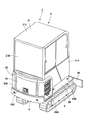
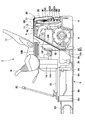
- FIG. 1 It is the front view which looked at the upper turning body of the state which opened the rear cover from the same position as FIG. It is a perspective view which shows the upper turning body which abbreviate
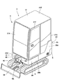
- a small hydraulic excavator 1 is configured as a cab specification mini excavator.
- This small hydraulic excavator 1 includes a self-propelled lower traveling body 2, an upper revolving body 3 that is turnably mounted on the lower traveling body 2, and a front side and a rearward front side of the upper revolving body 3. It is comprised with the front apparatus 4 which is provided so that the elevating motion can be performed, and performs the excavation work of earth and sand.
- the small hydraulic excavator 1 is used for dismantling work inside the building and excavation work in a narrow place in a street, the machine weight is suppressed to about 0.7 to 8 tons, for example.
- an ultra-compact cab-type hydraulic excavator having a machine weight of 2 tons or less is exemplified among mini excavators.
- the width of each of the lower traveling body 2, the upper swing body 3, and a cab 21 described later is set to be substantially the same.
- the left side cover 25 ⁇ / b> A of the engine cover portion 25 and the left panel 21 ⁇ / b> C of the cab 21 form the same vertical plane.
- the right side cover 25B of the engine cover portion 25 and the right panel 21D of the cab 21 form the same vertical plane.
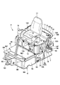
- the ultra-small hydraulic excavator 1 has a structure in which a space for arranging various mounted devices on the revolving frame 5 is narrow, and the seat 17 is arranged above the fuel tank 34 and the hydraulic oil tank 35. Yes.
- the revolving frame 5 is formed to be long in the front and rear directions, so that a living space for the operator can be secured and the cab 21 can be mounted on the revolving frame 5.
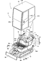
- the upper swing body 3 includes a swing frame 5, a counterweight 6, an engine 7, a hydraulic pump 8, a support member 9, a partition member 11, a base member 14, a footrest member 16, which will be described later.
- the cab 21, the exterior cover 23, the seal attachment portion 30, and the seal member 31 are configured.
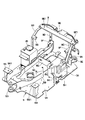
- the turning frame 5 is provided on the lower traveling body 2 so as to be capable of turning, and constitutes a support structure (base) for the upper turning body 3.
- the revolving frame 5 includes a bottom plate 5A formed in a rectangular shape extending in the front and rear directions using a thick steel plate and the like, and extends in the front and rear directions on the bottom plate 5A.
- the left vertical plate 5B and the right vertical plate 5C are erected in such a manner.
- a support bracket 5D is provided at the front ends of the left and right vertical plates 5B and 5C, and the front device 4 is supported by the support bracket 5D so as to be swingable in the left and right directions.
- a left rear bracket 5E is provided at a rear end portion of the left vertical plate 5B, and a left rear leg portion 9C of a support member 9 described later is attached to the left rear bracket 5E.
- a right rear bracket 5F is provided at the rear end of the right vertical plate 5C, and a right rear leg portion 9D of the support member 9 is attached to the right rear bracket 5F.
- a horizontal plate 5G that extends in the left and right directions across the front and rear intermediate portions of the left vertical plate 5B is erected on the front and rear intermediate portions of the bottom plate 5A.
- the horizontal plate 5G extends from the right vertical plate 5C to the left end of the bottom plate 5A beyond the left vertical plate 5B.
- the left end portion of the horizontal plate 5G is a left front bracket 5H, and the left front leg portion 9A of the support member 9 is attached to the left front bracket 5H.
- a right front bracket 5J is provided at the right end located on the extension line of the horizontal plate 5G in the bottom plate 5A and rises upward from the bottom plate 5A.
- the right front leg portion 9B of the support member 9 is attached to the right front bracket 5J.
- a left pedestal support member 5K made of a plate body bent in an inverted J shape is provided to extend upward from the bottom plate 5A at the front and rear intermediate portions at the left end portion of the bottom plate 5A.
- a right pedestal support member 5L made of a rod-like body extending upward and downward is provided at a portion facing the left pedestal support member 5K in the left and right directions.
- a left front cab support member 5M having a female screw hole 5M1 on its upper surface is provided upright at a corner on the left front side of the bottom plate 5A.
- the left front cab support member 5M has an elastic member (not shown) screwed into the female screw hole 5M1, and elastically supports the left front side of the cab 21 described later via the elastic member.
- a right front cab support member 5N having a female screw hole 5N1 on its upper surface is provided upright at a corner on the right front side of the bottom plate 5A.
- an elastic member (not shown) is screwed into the female screw hole 5N1 in substantially the same manner as the left front cab support member 5M, and the right front side of the cab 21 is elastically moved through the elastic member. I support it.
- the revolving frame 5 configured in this manner has a length dimension (total length dimension) in the front and rear directions larger than that of the lower traveling body 2.
- a cab 21 described later can be mounted on the revolving frame 5 while securing a living space for the operator.
- the counterweight 6 is attached to the rear side of the swivel frame 5.
- the counterweight 6 balances the weight with the front device 4, and is configured as a heavy article formed by casting, for example.
- the counterweight 6 can be disposed at a position away from the turning center by forming the turning frame 5 long in the forward and backward directions. Thereby, the counterweight 6 can keep the height dimension low while maintaining the weight balance with the front device 4.
- a striker 6 ⁇ / b> B for holding a rear cover 25 ⁇ / b> C of an engine cover portion 25 constituting an exterior cover 23 described later is attached to the center position of the upper surface 6 ⁇ / b> A of the counterweight 6. It has been.
- the engine 7 constitutes a prime mover disposed in an engine room 26 described later.
- the engine 7 drives the hydraulic pump 8 and is mounted on the front side of the counterweight 6 in a horizontally placed state extending leftward and rightward on the rear side of the turning frame 5.
- the engine 7 is provided with, for example, a hydraulic pump 8 located on the left side in the left and right directions, and a cooling fan (not shown) on the right side.
- the hydraulic pump 8 is driven by the engine 7 to supply hydraulic oil to hydraulic actuators provided in the lower traveling body 2, the front device 4, and the like.
- a heat exchange device (not shown) for cooling engine coolant, hydraulic oil, etc. is provided at a position facing the cooling fan.
- a hybrid prime mover provided with an electric motor for assisting in the engine can be used, or only the electric motor can be used as the prime mover.
- the support member 9 is provided on the turning frame 5 so as to straddle the engine 7.
- a partition member 11, a pedestal member 14, a rear side of the cab 21, and the like which are described later are attached to the support member 9.
- the support member 9 includes a left front leg 9A, a right front leg 9B, a left rear leg 9C, a right rear leg 9D, and a support base 9E. .
- the left front leg portion 9A located at the left end portion of the turning frame 5 extends obliquely rearward toward the upper side, and the lower end is fixed to the left front bracket 5H of the turning frame 5 using a bolt (not shown).
- the right front leg portion 9B located at the right end portion of the revolving frame 5 extends obliquely rearward toward the upper side, and the lower end is fixed to the right front bracket 5J of the revolving frame 5 using a bolt.
- the lower end of the left rear leg portion 9 ⁇ / b> C is fixed to the left rear bracket 5 ⁇ / b> E of the revolving frame 5 using a bolt.
- the lower right leg 9D has a lower end extending in the upward and downward directions, and is fixed to the right rear bracket 5F of the revolving frame 5 using a bolt.
- the support base 9E is fixed to the upper ends of the leg portions 9A, 9B, 9C, 9D.
- the support base 9E is formed as a strength member extending in the left and right directions.
- the support base 9E is provided with two bolt insertion holes 9E1 located on both sides in the left and right directions. In each bolt insertion hole 9E1, a lower portion of an elastic support 10 described later is fixed using a bolt. Thereby, the support base 9 ⁇ / b> E supports the rear side of the cab 21 via the elastic supports 10.
- a left support member 9F made of an angle material or the like protrudes forward from the upper side of the left front leg portion 9A.
- a right support member 9G made of an angle material or the like protrudes leftward from an intermediate portion in the upper and lower directions of the right front leg portion 9B.
- the elastic support 10 is attached to the left and right sides of the support base 9E of the support member 9 (only the left side is shown in FIGS. 4 and 8).
- the elastic support body 10 is mainly composed of a cylindrical rubber material having elasticity, and has a structure in which upper and lower portions are attached using bolts and nuts.
- the elastic support 10 has a lower part fixed to a bolt insertion hole 9E1 of a support base 9E that constitutes the support member 9, and an upper part that is a bolt insertion hole of the rear mounting plate 21H that constitutes the cab 21. It is fixed to 21H1.
- the elastic support body 10 can elastically support the rear side of the cab 21 on the support member 9.
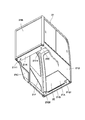
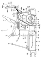
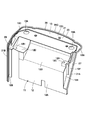
- the partition member 11 is supported between the turning frame 5 and the support base 9E of the support member 9, and covers the front side and the upper side of the engine 7.
- the partition member 11 partitions the engine chamber 26 and the front side of the engine chamber 26, that is, a driver's cab 22 described later.
- the partition member 11 is configured by a plate-like body including a front plate 12 that covers the front side of the engine 7 and an upper plate 13 that covers the upper side of the engine 7.
- the partition member 11 is formed with a width dimension equivalent to the full width dimension of the swivel frame 5.
- the partition member 11 partitions the engine compartment 26 (engine 7) and the cab 22 so that heat and operating noise generated by the engine 7 can be blocked from being transmitted to the cab 22 side.
- the engine compartment 26 can be sealed from the outside simply by surrounding the partition member 11 with an exterior cover 23 described later. it can.
- the front plate 12 includes a vertical plate 12A extending upward from the horizontal plate 5G of the revolving frame 5, an inclined plate 12B extending obliquely rearward from the upper end of the vertical plate 12A, and the inclined plate
- a left support plate 12C formed in a small step shape located on the left side of the plate 12B, and a right support plate 12D formed in a step shape larger than the left support plate 12C located on the right side of the inclined plate 12B;
- a side plate 12E formed over the vertical plate 12A and the inclined plate 12B, and a left end edge bent leftward from the rear end edge of the side plate 12E and extending leftward and connected to a lower portion of the vertical plate 12A
- the plate 12F and a right end edge plate 12G extending downward from the right end portion of the right support plate 12D.
- the left support plate 12C and the right support plate 12D are provided with bolt insertion holes 12H for inserting bolts 15 described later.
- the left end edge plate 12F faces the left front leg portion 9A of the support member 9, and the right end edge plate 12G faces the right front leg portion 9B of the support member 9. Furthermore, the edge of the left edge plate 12F is a part of a left edge 27 described later, and the edge of the right edge plate 12G is a part of a right edge 28 described later.
- the upper surface plate portion 13 is formed as a substantially rectangular horizontal plate body extending backward from the upper end of the inclined plate 12B and the right support plate 12D of the front surface plate portion 12. Thereby, the upper surface plate portion 13 covers the upper side of the engine 7.
- Support body insertion holes 13 ⁇ / b> A for inserting the elastic support bodies 10 attached to the support base 9 ⁇ / b> E of the support member 9 are provided on both the left and right sides of the upper surface plate portion 13.
- the edge of the left edge plate 13B of the upper surface plate 13 is a part of a left edge 27 described later, and the edge of the right edge plate 13C is a part of a right edge 28 described later.
- the edge portion of the rear end edge plate 13D of the upper surface plate portion 13 is a rear edge portion 29 described later.
- the lower portion of the vertical plate 12A of the front plate portion 12 is fixed to the horizontal plate 5G of the revolving frame 5 using bolts, and the upper surface plate portion 13 is fixed to the support base 9E of the revolving frame 5. It is fixed using bolts.
- the left support plate 12C of the front plate 12 is placed on the left support member 9F of the support member 9, and is attached to the left support member 9F together with the base member 14.
- the right support plate 12D is placed on the right support member 9G of the support member 9, and is attached to the right support member 9G together with the base member 14.
- the base member 14 is located on the front side of the partition member 11 and is provided between the revolving frame 5 and the front plate portion 12 of the partition member 11.
- a seat 17 (described later) is attached on the base member 14.
- the pedestal member 14 has a space for accommodating a fuel tank 34 and a hydraulic oil tank 35 to be described later on the lower side thereof. Thereby, even if it is the ultra-compact hydraulic shovel 1, since the two tanks 34 and 35 can be arrange
- the pedestal member 14 includes a front plate 14A that is positioned on the front side and is erected on the revolving frame 5 and a flat seat mounting plate 14B that extends rearward from the top of the front plate 14A. At the rear part of the seat mounting plate 14B, bolt insertion holes 14C are provided at the left and right corners.
- the base member 14 is arranged side by side on the front side of the partition member 11, and the lower side of the front plate 14 ⁇ / b> A is attached to the left and right base support members 5 ⁇ / b> K and 5 ⁇ / b> L of the revolving frame 5.
- the bolts 15 inserted into the respective bolt insertion holes 14 ⁇ / b> C are inserted into the bolt insertion holes 12 ⁇ / b> H of the front plate portion 12 constituting the partition member 11, and the respective support members of the support member 9. It is attached to the support member 9 together with the partition member 11 by being screwed to 9F and 9G.
- the footrest member 16 is located on the front side of the base member 14 and is provided on the revolving frame 5.
- the footrest member 16 is a space where an operator sitting on the seat 17 places his / her foot, and forms a floor board in the cab 21.
- a traveling operation lever / pedal 20 described later is disposed on the front side of the footrest member 16.
- the seat 17 is provided on the seat mounting plate 14 ⁇ / b> B of the base member 14.
- the seat 17 is for an operator to sit on.
- a left work operation lever 18 and a right work operation lever 19 are provided on both the left and right sides of the seat 17. These operating levers 18 and 19 are operated manually by an operator to operate the front device 4 and the like.
- a traveling operation lever / pedal 20 is provided at a front position of the footrest member 16 in front of the seat 17. The traveling operation lever / pedal 20 causes the lower traveling body 2 to travel by being manually operated or stepped on by an operator.
- the cab 21 is provided above the partition member 11, the base member 14, and the footrest member 16 so as to cover the seat 17 and the like.
- the cab 21 is formed in a box shape by a front panel 21A, a rear panel 21B, a left panel 21C, a right panel 21D, and an upper panel 21E.
- a door 21F that is opened and closed when getting on and off is rotatably attached to the left panel 21C.
- a front mounting plate 21 ⁇ / b> G extending in the left and right directions along the front panel 21 ⁇ / b> A is provided at the lower portion of the front panel 21 ⁇ / b> A of the cab 21.
- Bolt insertion holes 21G1 are provided at both the left and right positions of the front mounting plate 21G. These bolt insertion holes 21G1 are positions corresponding to the female screw holes 5M1 and 5N1 of the front cab support members 5M and 5N constituting the revolving frame 5. Therefore, the front mounting plate 21G screws the bolts (not shown) inserted through the bolt insertion holes 21G1 to the upper portions of the elastic members attached to the front cab support members 5M and 5N of the turning frame 5. Thus, it is elastically supported by the front part of the revolving frame 5.
- a rear mounting plate 21H extending leftward and rightward along the rear panel 21B is provided at the lower portion of the rear panel 21B of the cab 21.
- bolt insertion holes 21H1 are respectively provided on the left and right side positions of the mounting plate 21H.
- Each of these bolt insertion holes 21H1 is located at a position corresponding to each bolt insertion hole 9E1 of the support base 9E constituting the support member 9. Accordingly, the rear mounting plate 21H is elastically supported by the support member 9 by screwing bolts (not shown) inserted through the respective bolt insertion holes 21H1 into the upper portion of the elastic support body 10.
- the cab 21 mounted on the revolving frame 5 can also be formed long in the front and rear directions.
- the cab 21 having a sufficient living space can be disposed on the upper swing body 3.
- the width of the cab 21 is set to be approximately the same as the width of the swivel frame 5. Therefore, the maximum width dimension can be obtained as the cab 21 with respect to the limited installation space on the revolving frame 5, and also in this respect, the living space can be widened.
- the living space in the cab 21 is a cab 22 in which an operator gets in.
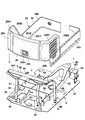
- the exterior cover 23 is arranged so as to surround the revolving frame 5, and is composed of a plurality of plates that rise from the periphery of the bottom plate 5 ⁇ / b> A of the revolving frame 5.
- the exterior cover 23 covers the front cover portion 24 that covers the periphery of the footrest member 16 that is the front lower side portion of the cab 21, and the left side, right side, and rear side of the engine compartment 26 that is the rear lower side portion of the cab 21.
- the engine cover part 25 is comprised.
- the front cover part 24 is provided across the revolving frame 5 and the footrest member 16. As shown in FIG. 10, the front cover portion 24 extends in the front and rear directions along the left side of the footrest member 16, and extends along the right side of the footrest member 16 and the left skirt cover 24 ⁇ / b> A having the front side bent to the right side. It includes a right skirt cover 24B extending in the front and rear directions and having the front side bent to the left.
- the engine cover part 25 as a motor cover part includes a left side cover 25A that covers the left side of the engine room 26, a right side cover 25B that covers the right side of the engine room 26, the left side cover 25A, and the right side cover 25B. And a rear cover 25C that covers the rear side of the engine chamber 26.
- the left side cover 25A, the right side cover 25B and the rear cover 25C constituting the engine cover part 25, and the left skirt cover 24A and the right skirt cover 24B constituting the front cover part 24 are the revolving frame 5 and the support.
- the structure such as the member 9 is detachably attached using bolts.
- the left side cover 25 ⁇ / b> A is disposed between the bottom plate 5 ⁇ / b> A of the revolving frame 5, the counterweight 6 and the cab 21.
- This left side cover 25A is formed as a plate-like body bent so as to go around from the left side of the revolving frame 5 to the rear side.
- the upper outer end 25A1 of the left side cover 25A extends obliquely upward along the left end edge plate 12F of the front plate 12 constituting the partition member 11, and the left end edge plate 13B of the upper surface plate 13. Extends horizontally along the left edge plate 13B.
- a seal surface 25A2 (an inner surface part surrounded by a dotted line) facing a seal member 31 described later and closely contacting the seal cylinder 33. ing.
- the seal surface 25A2 of the left side cover 25A is formed as a smooth surface so that it can be in close contact with the seal member 31 without a gap. Specifically, the seal surface 25A2 comes into contact with a left side portion provided along a left edge portion 27 to be described later, in one long seal member 31.
- the smooth surface of the seal surface 25A2 is a shape in which there is almost no step (bend) that creates a gap with the seal cylinder 33 of the seal member 31. That is, the smooth surface of the seal surface 25A2 includes a gently curved surface that allows the seal tube 33 to be in close contact with each other without a gap, in addition to a substantially flat surface. Further, the left side cover 25A is detachably attached to the revolving frame 5, the support member 9 and the like using bolts, for example.
- the right side cover 25B faces the left side cover 25A and the engine chamber 26 in the left and right directions, and is disposed between the bottom plate 5A of the revolving frame 5, the counterweight 6 and the cab 21.
- the right side cover 25B is formed as a plate-like body bent so as to wrap around from the right side of the revolving frame 5 so as to be symmetrical with the left side cover 25A.
- the upper outer end 25B1 of the right side cover 25B extends upward along the right end edge plate 12G of the front plate 12 constituting the partition member 11, and at the position of the right end edge plate 13C of the upper surface plate 13. It extends in the horizontal direction along the right edge plate 13C.
- a seal surface 25B2 (an inner surface portion surrounded by a dotted line) facing a seal member 31 described later and closely contacting the seal cylinder 33.
- the seal surface 25B2 of the right side cover 25B is formed as a smooth surface with no step so that it can be in close contact with the seal cylinder 33 without a gap.
- the seal surface 25B2 comes into contact with a right side portion of the single seal member 31 provided along the right edge portion 28 described later.
- the front side portion of the right side cover 25B is attached to the support member 9 so that it can be opened and closed in the left and right directions, for example.
- the rear cover 25C is formed as a rectangular plate-shaped body surrounded by the left side cover 25A, the right side cover 25B, the upper surface 6A of the counterweight 6 and the rear panel 21B of the cab 21.
- the upper outer end 25C1 of the rear cover 25C extends left and right (horizontal direction) along the rear edge plate 13D at the position of the rear edge plate 13D of the upper surface plate portion 13 constituting the partition member 11. .
- a seal surface 25C2 (an inner surface portion surrounded by a dotted line) that faces the seal member 31 and is in close contact with the seal cylinder 33 is provided inside the outer end 25C1 of the rear cover 25C (on the engine chamber 26 side).
- the seal surface 25C2 of the rear cover 25C is formed as a smooth surface without a step so that the seal surface can be in close contact with the seal cylinder 33 when facing the seal cylinder 33, like the seal surfaces 25A2 and 25B2.
- the seal surface 25 ⁇ / b> C ⁇ b> 2 comes into contact with a rear side portion provided along a rear edge portion 29 described later in one seal member 31.
- the rear cover 25C is attached to the support member 9 via a link mechanism 25C3. Accordingly, as shown in FIG. 7, the rear cover 25C can be opened by lifting the rear cover 25C upward with the link mechanism 25C3 as a fulcrum.
- a catch 25C4 is provided at a lower position of the rear cover 25C, and the catch 25C4 can hold the rear cover 25C in a closed state by engaging with the striker 6B on the counterweight 6 side.
- the engine room 26 is surrounded by the bottom plate 5 ⁇ / b> A of the revolving frame 5, the partition member 11, and the engine cover part 25 of the exterior cover 23.
- the engine room 26 constitutes a prime mover room and houses the engine 7 and the hydraulic pump 8.
- the left edge portion 27 is formed as the left edge portion of the partition member 11.
- the left edge 27 is formed as an edge of the vertical plate 12A, the left edge plate 12F of the front plate 12 constituting the partition member 11 and the left edge plate 13B of the upper plate 13. .
- the right edge portion 28 is formed as an edge portion on the right side of the partition member 11 that is opposite to the left edge portion 27 in the left and right directions.
- the right edge portion 28 is formed as an edge of the right edge plate 12G of the front plate 12 and the right edge plate 13C of the upper plate 13 constituting the partition member 11 in substantially the same manner as the left edge 27. Has been.
- the rear edge 29 is located between the left edge 27 and the right edge 28 and is formed as an end edge on the rear side of the partition member 11.
- the rear edge portion 29 is formed as an edge portion of the rear end edge plate 13 ⁇ / b> D that constitutes the partition member 11.
- the rear edge 29 is gently curved so that the left and right central portions protrude rearward.
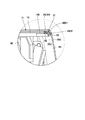
- the seal attachment portion 30 is formed as a part of the partition member 11.
- the seal attachment portion 30 is formed by projecting end edges of the left edge portion 27, the right edge portion 28 and the rear edge portion 29.
- the seal attachment portion 30 has an attachment allowance of a predetermined width that is substantially continuous from the lower end position of the left edge portion 27 to the lower end position of the right edge portion 28 via the rear edge portion 29, that is, a narrow pattern indicated by a dot pattern in FIG. It is a range of width.
- the predetermined width of the seal attachment portion 30 is a range sandwiched between attachment portions 32 of a seal member 31 described later. In this case, the seal attachment portion 30 is formed in a flat shape with few folds and distortion so that the attachment portion 32 of the seal member 31 can be securely sandwiched.
- the seal member 31 is provided on the peripheral edge of the partition member 11.
- the seal member 31 extends continuously along the left edge portion 27, the right edge portion 28, and the rear edge portion 29 of the partition member 11.
- the seal member 31 is configured as a single member that is continuously attached to the seal attachment portion 30 provided at the left edge portion 27, the right edge portion 28, and the rear edge portion 29.
- the seal member 31 includes an attachment portion 32 having a U-shaped cross section sandwiching the seal attachment portion 30, and a cylindrical seal tube 33 provided at the distal end portion of the attachment portion 32.
- the seal member 31 is called a weather strip, and is formed of an elastic resin material (for example, a foaming urethane resin material).
- the configuration of the seal member 31 described above is an example of a generally used one, and other shapes, for example, a solid seal portion can be used instead of a hollow seal cylinder.
- the seal member 31 is formed as a single seal member by, for example, pulling out a roll-shaped product formed in a long shape by extrusion and cutting it into a desired length.
- the seal member 31 is integrally disposed around the partition member 11 by attaching the attachment portion 32 to the seal attachment portion 30. In this case, the single seal member 31 can be easily attached to the partition member 11.
- the seal member 31 attached to the seal attachment portion 30 of the partition member 11 has a position corresponding to the left edge portion 27 as the left seal portion 31A and a position corresponding to the right edge portion 28 as the right seal portion 31B, and the rear edge portion.
- a position corresponding to 29 is the rear seal portion 31C.
- the seal member 31 separated from the partition member 11 is shown in a state of being held in a shape corresponding to the seal attachment portion 30 so that the attachment structure can be easily understood.
- the separated seal member 31 is actually a single string-like body or strip-like body that can be freely deformed.
- the seal member 31 attached to the partition member 11 is pressed against the seal cylinder 33 by the seal surface 25A2 of the left side cover 25A of the engine cover part 25, the seal surface 25B2 of the right side cover 25B, and the seal surface 25C2 of the rear cover 25C. .
- the seal member 31 can seal between the partition member 11 and the engine cover part 25 by the seal cylinder 33 being deformed and being in close contact with the seal surfaces 25A2, 25B2, and 25C2.
- the single seal member 31 is also present between the left side cover 25A and the rear cover 25C of the engine cover portion 25 and between the right side cover 25B and the rear cover 25C. Therefore, the seal member 31 can suppress entry of foreign matter, rainwater, and the like from between the covers 25A, 25B, and 25C, and leakage of hot air generated from the engine 7.
- the fuel tank 34 is mounted on the left side of the bottom plate 5 ⁇ / b> A at the middle part of the front and rear directions of the revolving frame 5.
- the fuel tank 34 stores fuel supplied to the engine 7.
- the hydraulic oil tank 35 is mounted on the right side of the bottom plate 5A which is opposite to the fuel tank 34 in the left and right directions.
- the hydraulic oil tank 35 stores hydraulic oil supplied to the hydraulic pump 8.
- the fuel tank 34 and the hydraulic oil tank 35 are stored below the pedestal member 14.
- the cab 21 does not need to be disposed avoiding the tanks 34 and 35, so the cab 21 is formed over the entire width of the revolving frame 5. can do. Therefore, the cab 22 and the engine compartment 26 can be partitioned only by the partition member 11. As a result, it is possible to prevent external foreign matter, dust, rainwater, etc. from entering the engine chamber 26 only by sealing the space between the partition member 11 and the engine cover portion 25 of the exterior cover 23 with the seal member 31. Moreover, it is possible to prevent the hot air and the operation sound in the engine chamber 26 from being transmitted to the operator side.
- the earth removal plate 36 is provided on the front side of the lower traveling body 2 so as to extend leftward and rightward and to be rotatable upward and downward.
- This earth removal board 36 performs, for example, earth and sand discharge, earth removal work including leveling, and snow removal work.
- the hydraulic excavator 1 according to the present embodiment has the above-described configuration. Next, the operation of the hydraulic excavator 1 will be described.
- the ultra-small hydraulic excavator 1 is transported to the work site while being loaded on the truck bed.
- the operator gets into the cab 21 and sits on the seat 17.
- the operating lever / pedal 20 By operating the operating lever / pedal 20 for traveling in this state, the lower traveling body 2 can be driven to move the hydraulic excavator 1 forward or backward.
- the operator seated on the seat 17 operates the left and right operation levers 18 and 19 to operate the front device 4 to perform the dismantling work inside the building and the side ditching work in a narrow street. be able to.
- the partition member 11 is located on the left side in the left and right directions, the left edge 27 extending from the front plate 12 to the upper plate 13, and the left edge 27 and the left,
- the upper surface plate portion positioned on the opposite side of the right direction and extending between the front edge plate portion 12 and the upper surface plate portion 13 and between the left edge portion 27 and the right edge portion 28. 13 and a rear edge 29 on the rear side.
- the partition member 11 is provided with a seal member 31 extending continuously along the left edge portion 27, the right edge portion 28, and the rear edge portion 29.
- each of the covers 25A, 25B, 25C of the engine cover portion 25 constituting the exterior cover 23 has seal surfaces 25A2, 25B2, 25C2 facing the seal member 31 and being in close contact with the seal member 31, respectively. Is provided.
- the seal member 31 can seal between the partition member 11 and the engine cover portion 25. As a result, the seal member 31 can suppress external foreign matter, dust, and rainwater from entering the engine compartment 26. On the other hand, even if the engine 7 in the engine chamber 26 generates heat and operating noise, the hot air and operating noise at this time can be enclosed in the engine chamber 26 by the seal member 31.
- the seal member 31 is formed as a single seal member that extends continuously along the seal attachment portion 30 provided on the left edge portion 27, the right edge portion 28, and the rear edge portion 29 of the partition member 11. .
- the one sealing member 31 can be easily attached to the partition member 11.
- the single sealing member 31 is also present between the left side cover 25A and the rear cover 25C and between the right side cover 25B and the rear cover 25C, and can have a sealing function.
- seal surfaces 25A2, 25B2, and 25C2 provided on the left side cover 25A, the right side cover 25B, and the rear cover 25C of the engine cover portion 25 are formed so that the portions facing the seal member 31 are smooth surfaces. .
- the seal member 31 can reliably bring the seal cylinder 33 into close contact with the seal surfaces 25A2, 25B2, and 25C2, and can improve the sealing performance (airtightness and sustainability).
- the left edge portion 27, the right edge portion 28, and the rear edge portion 29 of the partition member 11 have seal attachment portions 30 formed by projecting end edges. Thereby, the sealing member 31 which consists of a single member using this seal attaching part 30 can be attached easily.
Landscapes
- Engineering & Computer Science (AREA)
- Mechanical Engineering (AREA)
- Mining & Mineral Resources (AREA)
- Civil Engineering (AREA)
- General Engineering & Computer Science (AREA)
- Structural Engineering (AREA)
- Chemical & Material Sciences (AREA)
- Combustion & Propulsion (AREA)
- Transportation (AREA)
- Component Parts Of Construction Machinery (AREA)
- Seal Device For Vehicle (AREA)
- Body Structure For Vehicles (AREA)
Applications Claiming Priority (2)
| Application Number | Priority Date | Filing Date | Title |
|---|---|---|---|
| JP2016-064096 | 2016-03-28 | ||
| JP2016064096A JP6585534B2 (ja) | 2016-03-28 | 2016-03-28 | 小型の油圧ショベル |
Publications (1)
| Publication Number | Publication Date |
|---|---|
| WO2017168818A1 true WO2017168818A1 (ja) | 2017-10-05 |
Family
ID=59963804
Family Applications (1)
| Application Number | Title | Priority Date | Filing Date |
|---|---|---|---|
| PCT/JP2016/083391 Ceased WO2017168818A1 (ja) | 2016-03-28 | 2016-11-10 | 小型の油圧ショベル |
Country Status (2)
| Country | Link |
|---|---|
| JP (1) | JP6585534B2 (enExample) |
| WO (1) | WO2017168818A1 (enExample) |
Cited By (1)
| Publication number | Priority date | Publication date | Assignee | Title |
|---|---|---|---|---|
| CN115198834A (zh) * | 2022-07-29 | 2022-10-18 | 天津移山工程机械有限公司 | 一种驾驶室双座位箱体结构及履带式推土机 |
Families Citing this family (2)
| Publication number | Priority date | Publication date | Assignee | Title |
|---|---|---|---|---|
| EP4406780A3 (en) | 2019-06-26 | 2025-01-08 | Kubota Corporation | Work machine |
| JP7191782B2 (ja) * | 2019-06-26 | 2022-12-19 | 株式会社クボタ | 作業機 |
Citations (5)
| Publication number | Priority date | Publication date | Assignee | Title |
|---|---|---|---|---|
| JP2000265729A (ja) * | 1999-03-18 | 2000-09-26 | Shin Caterpillar Mitsubishi Ltd | 開閉装置 |
| JP2001140647A (ja) * | 1999-11-11 | 2001-05-22 | Hitachi Constr Mach Co Ltd | 建設機械 |
| JP2005119545A (ja) * | 2003-10-17 | 2005-05-12 | Hitachi Constr Mach Co Ltd | 建設機械 |
| JP2015074015A (ja) * | 2013-10-09 | 2015-04-20 | 株式会社デンソー | 電力変換装置 |
| WO2016043345A1 (ja) * | 2015-09-30 | 2016-03-24 | 株式会社小松製作所 | 油圧ショベル |
Family Cites Families (1)
| Publication number | Priority date | Publication date | Assignee | Title |
|---|---|---|---|---|
| US8978812B2 (en) * | 2011-10-05 | 2015-03-17 | Hitachi Construction Machinery Co., Ltd. | Construction machine |
-
2016
- 2016-03-28 JP JP2016064096A patent/JP6585534B2/ja active Active
- 2016-11-10 WO PCT/JP2016/083391 patent/WO2017168818A1/ja not_active Ceased
Patent Citations (5)
| Publication number | Priority date | Publication date | Assignee | Title |
|---|---|---|---|---|
| JP2000265729A (ja) * | 1999-03-18 | 2000-09-26 | Shin Caterpillar Mitsubishi Ltd | 開閉装置 |
| JP2001140647A (ja) * | 1999-11-11 | 2001-05-22 | Hitachi Constr Mach Co Ltd | 建設機械 |
| JP2005119545A (ja) * | 2003-10-17 | 2005-05-12 | Hitachi Constr Mach Co Ltd | 建設機械 |
| JP2015074015A (ja) * | 2013-10-09 | 2015-04-20 | 株式会社デンソー | 電力変換装置 |
| WO2016043345A1 (ja) * | 2015-09-30 | 2016-03-24 | 株式会社小松製作所 | 油圧ショベル |
Cited By (2)
| Publication number | Priority date | Publication date | Assignee | Title |
|---|---|---|---|---|
| CN115198834A (zh) * | 2022-07-29 | 2022-10-18 | 天津移山工程机械有限公司 | 一种驾驶室双座位箱体结构及履带式推土机 |
| CN115198834B (zh) * | 2022-07-29 | 2024-06-07 | 天津移山工程机械有限公司 | 一种驾驶室双座位箱体结构及履带式推土机 |
Also Published As
| Publication number | Publication date |
|---|---|
| JP2017179738A (ja) | 2017-10-05 |
| JP6585534B2 (ja) | 2019-10-02 |
Similar Documents
| Publication | Publication Date | Title |
|---|---|---|
| US7481289B2 (en) | Swiveling work machine | |
| JP4976594B2 (ja) | 建設機械 | |
| WO2013051609A1 (ja) | 建設機械 | |
| JP4233595B2 (ja) | 作業車両 | |
| JP5691944B2 (ja) | 上部旋回体の機器支持構造 | |
| JP4814235B2 (ja) | 建設機械のキャブ構造 | |
| JP6585534B2 (ja) | 小型の油圧ショベル | |
| WO2017163477A1 (ja) | 小型の油圧ショベル | |
| US10267017B2 (en) | Small-sized construction machine | |
| JP2006056325A (ja) | 建設機械用キャブ | |
| JP2005119362A (ja) | 建設機械 | |
| JP4394518B2 (ja) | 建設機械 | |
| JP6479647B2 (ja) | 小型の建設機械 | |
| JP5123248B2 (ja) | 建設機械 | |
| JP4256219B2 (ja) | 建設機械 | |
| JP2013237985A (ja) | 建設機械 | |
| JP2007092278A (ja) | バックホーの上部構造 | |
| JP2005336829A (ja) | 建設機械の旋回フレーム | |
| JP4381364B2 (ja) | バックホー | |
| JP4703334B2 (ja) | バックホー | |
| JP6884732B2 (ja) | 遠隔操作式小型油圧ショベル | |
| JP4544514B2 (ja) | 建設機械用キャブ | |
| JP2017082511A (ja) | 小型の建設機械 | |
| JP2007092281A (ja) | バックホー | |
| JP2005344473A (ja) | 建設機械 |
Legal Events
| Date | Code | Title | Description |
|---|---|---|---|
| NENP | Non-entry into the national phase |
Ref country code: DE |
|
| 121 | Ep: the epo has been informed by wipo that ep was designated in this application |
Ref document number: 16897034 Country of ref document: EP Kind code of ref document: A1 |
|
| 122 | Ep: pct application non-entry in european phase |
Ref document number: 16897034 Country of ref document: EP Kind code of ref document: A1 |