WO2017159203A1 - 自動変速機の制御装置 - Google Patents
自動変速機の制御装置 Download PDFInfo
- Publication number
- WO2017159203A1 WO2017159203A1 PCT/JP2017/005798 JP2017005798W WO2017159203A1 WO 2017159203 A1 WO2017159203 A1 WO 2017159203A1 JP 2017005798 W JP2017005798 W JP 2017005798W WO 2017159203 A1 WO2017159203 A1 WO 2017159203A1
- Authority
- WO
- WIPO (PCT)
- Prior art keywords
- compensation
- phase
- automatic transmission
- phase advance
- vehicle
- Prior art date
- Legal status (The legal status is an assumption and is not a legal conclusion. Google has not performed a legal analysis and makes no representation as to the accuracy of the status listed.)
- Ceased
Links
Images

Classifications
-
- B—PERFORMING OPERATIONS; TRANSPORTING
- B60—VEHICLES IN GENERAL
- B60W—CONJOINT CONTROL OF VEHICLE SUB-UNITS OF DIFFERENT TYPE OR DIFFERENT FUNCTION; CONTROL SYSTEMS SPECIALLY ADAPTED FOR HYBRID VEHICLES; ROAD VEHICLE DRIVE CONTROL SYSTEMS FOR PURPOSES NOT RELATED TO THE CONTROL OF A PARTICULAR SUB-UNIT
- B60W10/00—Conjoint control of vehicle sub-units of different type or different function
- B60W10/02—Conjoint control of vehicle sub-units of different type or different function including control of driveline clutches
-
- B—PERFORMING OPERATIONS; TRANSPORTING
- B60—VEHICLES IN GENERAL
- B60W—CONJOINT CONTROL OF VEHICLE SUB-UNITS OF DIFFERENT TYPE OR DIFFERENT FUNCTION; CONTROL SYSTEMS SPECIALLY ADAPTED FOR HYBRID VEHICLES; ROAD VEHICLE DRIVE CONTROL SYSTEMS FOR PURPOSES NOT RELATED TO THE CONTROL OF A PARTICULAR SUB-UNIT
- B60W10/00—Conjoint control of vehicle sub-units of different type or different function
- B60W10/02—Conjoint control of vehicle sub-units of different type or different function including control of driveline clutches
- B60W10/023—Fluid clutches
-
- B—PERFORMING OPERATIONS; TRANSPORTING
- B60—VEHICLES IN GENERAL
- B60W—CONJOINT CONTROL OF VEHICLE SUB-UNITS OF DIFFERENT TYPE OR DIFFERENT FUNCTION; CONTROL SYSTEMS SPECIALLY ADAPTED FOR HYBRID VEHICLES; ROAD VEHICLE DRIVE CONTROL SYSTEMS FOR PURPOSES NOT RELATED TO THE CONTROL OF A PARTICULAR SUB-UNIT
- B60W10/00—Conjoint control of vehicle sub-units of different type or different function
- B60W10/02—Conjoint control of vehicle sub-units of different type or different function including control of driveline clutches
- B60W10/024—Conjoint control of vehicle sub-units of different type or different function including control of driveline clutches including control of torque converters
-
- B—PERFORMING OPERATIONS; TRANSPORTING
- B60—VEHICLES IN GENERAL
- B60W—CONJOINT CONTROL OF VEHICLE SUB-UNITS OF DIFFERENT TYPE OR DIFFERENT FUNCTION; CONTROL SYSTEMS SPECIALLY ADAPTED FOR HYBRID VEHICLES; ROAD VEHICLE DRIVE CONTROL SYSTEMS FOR PURPOSES NOT RELATED TO THE CONTROL OF A PARTICULAR SUB-UNIT
- B60W10/00—Conjoint control of vehicle sub-units of different type or different function
- B60W10/02—Conjoint control of vehicle sub-units of different type or different function including control of driveline clutches
- B60W10/024—Conjoint control of vehicle sub-units of different type or different function including control of driveline clutches including control of torque converters
- B60W10/026—Conjoint control of vehicle sub-units of different type or different function including control of driveline clutches including control of torque converters of lock-up clutches
-
- B—PERFORMING OPERATIONS; TRANSPORTING
- B60—VEHICLES IN GENERAL
- B60W—CONJOINT CONTROL OF VEHICLE SUB-UNITS OF DIFFERENT TYPE OR DIFFERENT FUNCTION; CONTROL SYSTEMS SPECIALLY ADAPTED FOR HYBRID VEHICLES; ROAD VEHICLE DRIVE CONTROL SYSTEMS FOR PURPOSES NOT RELATED TO THE CONTROL OF A PARTICULAR SUB-UNIT
- B60W30/00—Purposes of road vehicle drive control systems not related to the control of a particular sub-unit, e.g. of systems using conjoint control of vehicle sub-units
- B60W30/18—Propelling the vehicle
- B60W30/188—Controlling power parameters of the driveline, e.g. determining the required power
- B60W30/1884—Avoiding stall or overspeed of the engine
-
- F—MECHANICAL ENGINEERING; LIGHTING; HEATING; WEAPONS; BLASTING
- F16—ENGINEERING ELEMENTS AND UNITS; GENERAL MEASURES FOR PRODUCING AND MAINTAINING EFFECTIVE FUNCTIONING OF MACHINES OR INSTALLATIONS; THERMAL INSULATION IN GENERAL
- F16H—GEARING
- F16H59/00—Control inputs to control units of change-speed- or reversing-gearings for conveying rotary motion
- F16H59/02—Selector apparatus
- F16H59/04—Ratio selector apparatus
- F16H59/06—Ratio selector apparatus the ratio being infinitely variable
-
- F—MECHANICAL ENGINEERING; LIGHTING; HEATING; WEAPONS; BLASTING
- F16—ENGINEERING ELEMENTS AND UNITS; GENERAL MEASURES FOR PRODUCING AND MAINTAINING EFFECTIVE FUNCTIONING OF MACHINES OR INSTALLATIONS; THERMAL INSULATION IN GENERAL
- F16H—GEARING
- F16H59/00—Control inputs to control units of change-speed- or reversing-gearings for conveying rotary motion
- F16H59/14—Inputs being a function of torque or torque demand
- F16H59/18—Inputs being a function of torque or torque demand dependent on the position of the accelerator pedal
-
- F—MECHANICAL ENGINEERING; LIGHTING; HEATING; WEAPONS; BLASTING
- F16—ENGINEERING ELEMENTS AND UNITS; GENERAL MEASURES FOR PRODUCING AND MAINTAINING EFFECTIVE FUNCTIONING OF MACHINES OR INSTALLATIONS; THERMAL INSULATION IN GENERAL
- F16H—GEARING
- F16H59/00—Control inputs to control units of change-speed- or reversing-gearings for conveying rotary motion
- F16H59/36—Inputs being a function of speed
-
- F—MECHANICAL ENGINEERING; LIGHTING; HEATING; WEAPONS; BLASTING
- F16—ENGINEERING ELEMENTS AND UNITS; GENERAL MEASURES FOR PRODUCING AND MAINTAINING EFFECTIVE FUNCTIONING OF MACHINES OR INSTALLATIONS; THERMAL INSULATION IN GENERAL
- F16H—GEARING
- F16H59/00—Control inputs to control units of change-speed- or reversing-gearings for conveying rotary motion
- F16H59/36—Inputs being a function of speed
- F16H59/38—Inputs being a function of speed of gearing elements
-
- F—MECHANICAL ENGINEERING; LIGHTING; HEATING; WEAPONS; BLASTING
- F16—ENGINEERING ELEMENTS AND UNITS; GENERAL MEASURES FOR PRODUCING AND MAINTAINING EFFECTIVE FUNCTIONING OF MACHINES OR INSTALLATIONS; THERMAL INSULATION IN GENERAL
- F16H—GEARING
- F16H59/00—Control inputs to control units of change-speed- or reversing-gearings for conveying rotary motion
- F16H59/68—Inputs being a function of gearing status
- F16H59/70—Inputs being a function of gearing status dependent on the ratio established
-
- F—MECHANICAL ENGINEERING; LIGHTING; HEATING; WEAPONS; BLASTING
- F16—ENGINEERING ELEMENTS AND UNITS; GENERAL MEASURES FOR PRODUCING AND MAINTAINING EFFECTIVE FUNCTIONING OF MACHINES OR INSTALLATIONS; THERMAL INSULATION IN GENERAL
- F16H—GEARING
- F16H61/00—Control functions within control units of change-speed- or reversing-gearings for conveying rotary motion ; Control of exclusively fluid gearing, friction gearing, gearings with endless flexible members or other particular types of gearing
- F16H61/04—Smoothing ratio shift
-
- F—MECHANICAL ENGINEERING; LIGHTING; HEATING; WEAPONS; BLASTING
- F16—ENGINEERING ELEMENTS AND UNITS; GENERAL MEASURES FOR PRODUCING AND MAINTAINING EFFECTIVE FUNCTIONING OF MACHINES OR INSTALLATIONS; THERMAL INSULATION IN GENERAL
- F16H—GEARING
- F16H61/00—Control functions within control units of change-speed- or reversing-gearings for conveying rotary motion ; Control of exclusively fluid gearing, friction gearing, gearings with endless flexible members or other particular types of gearing
- F16H61/14—Control of torque converter lock-up clutches
-
- F—MECHANICAL ENGINEERING; LIGHTING; HEATING; WEAPONS; BLASTING
- F16—ENGINEERING ELEMENTS AND UNITS; GENERAL MEASURES FOR PRODUCING AND MAINTAINING EFFECTIVE FUNCTIONING OF MACHINES OR INSTALLATIONS; THERMAL INSULATION IN GENERAL
- F16H—GEARING
- F16H61/00—Control functions within control units of change-speed- or reversing-gearings for conveying rotary motion ; Control of exclusively fluid gearing, friction gearing, gearings with endless flexible members or other particular types of gearing
- F16H61/66—Control functions within control units of change-speed- or reversing-gearings for conveying rotary motion ; Control of exclusively fluid gearing, friction gearing, gearings with endless flexible members or other particular types of gearing specially adapted for continuously variable gearings
-
- F—MECHANICAL ENGINEERING; LIGHTING; HEATING; WEAPONS; BLASTING
- F16—ENGINEERING ELEMENTS AND UNITS; GENERAL MEASURES FOR PRODUCING AND MAINTAINING EFFECTIVE FUNCTIONING OF MACHINES OR INSTALLATIONS; THERMAL INSULATION IN GENERAL
- F16H—GEARING
- F16H61/00—Control functions within control units of change-speed- or reversing-gearings for conveying rotary motion ; Control of exclusively fluid gearing, friction gearing, gearings with endless flexible members or other particular types of gearing
- F16H61/66—Control functions within control units of change-speed- or reversing-gearings for conveying rotary motion ; Control of exclusively fluid gearing, friction gearing, gearings with endless flexible members or other particular types of gearing specially adapted for continuously variable gearings
- F16H61/662—Control functions within control units of change-speed- or reversing-gearings for conveying rotary motion ; Control of exclusively fluid gearing, friction gearing, gearings with endless flexible members or other particular types of gearing specially adapted for continuously variable gearings with endless flexible members
-
- F—MECHANICAL ENGINEERING; LIGHTING; HEATING; WEAPONS; BLASTING
- F16—ENGINEERING ELEMENTS AND UNITS; GENERAL MEASURES FOR PRODUCING AND MAINTAINING EFFECTIVE FUNCTIONING OF MACHINES OR INSTALLATIONS; THERMAL INSULATION IN GENERAL
- F16H—GEARING
- F16H61/00—Control functions within control units of change-speed- or reversing-gearings for conveying rotary motion ; Control of exclusively fluid gearing, friction gearing, gearings with endless flexible members or other particular types of gearing
- F16H61/66—Control functions within control units of change-speed- or reversing-gearings for conveying rotary motion ; Control of exclusively fluid gearing, friction gearing, gearings with endless flexible members or other particular types of gearing specially adapted for continuously variable gearings
- F16H61/662—Control functions within control units of change-speed- or reversing-gearings for conveying rotary motion ; Control of exclusively fluid gearing, friction gearing, gearings with endless flexible members or other particular types of gearing specially adapted for continuously variable gearings with endless flexible members
- F16H61/66254—Control functions within control units of change-speed- or reversing-gearings for conveying rotary motion ; Control of exclusively fluid gearing, friction gearing, gearings with endless flexible members or other particular types of gearing specially adapted for continuously variable gearings with endless flexible members controlling of shifting being influenced by a signal derived from the engine and the main coupling
- F16H61/66259—Control functions within control units of change-speed- or reversing-gearings for conveying rotary motion ; Control of exclusively fluid gearing, friction gearing, gearings with endless flexible members or other particular types of gearing specially adapted for continuously variable gearings with endless flexible members controlling of shifting being influenced by a signal derived from the engine and the main coupling using electrical or electronical sensing or control means
-
- F—MECHANICAL ENGINEERING; LIGHTING; HEATING; WEAPONS; BLASTING
- F16—ENGINEERING ELEMENTS AND UNITS; GENERAL MEASURES FOR PRODUCING AND MAINTAINING EFFECTIVE FUNCTIONING OF MACHINES OR INSTALLATIONS; THERMAL INSULATION IN GENERAL
- F16H—GEARING
- F16H63/00—Control outputs from the control unit to change-speed- or reversing-gearings for conveying rotary motion or to other devices than the final output mechanism
- F16H63/40—Control outputs from the control unit to change-speed- or reversing-gearings for conveying rotary motion or to other devices than the final output mechanism comprising signals other than signals for actuating the final output mechanisms
- F16H63/46—Signals to a clutch outside the gearbox
-
- B—PERFORMING OPERATIONS; TRANSPORTING
- B60—VEHICLES IN GENERAL
- B60W—CONJOINT CONTROL OF VEHICLE SUB-UNITS OF DIFFERENT TYPE OR DIFFERENT FUNCTION; CONTROL SYSTEMS SPECIALLY ADAPTED FOR HYBRID VEHICLES; ROAD VEHICLE DRIVE CONTROL SYSTEMS FOR PURPOSES NOT RELATED TO THE CONTROL OF A PARTICULAR SUB-UNIT
- B60W50/00—Details of control systems for road vehicle drive control not related to the control of a particular sub-unit, e.g. process diagnostic or vehicle driver interfaces
- B60W2050/0001—Details of the control system
- B60W2050/0002—Automatic control, details of type of controller or control system architecture
- B60W2050/0008—Feedback, closed loop systems or details of feedback error signal
-
- F—MECHANICAL ENGINEERING; LIGHTING; HEATING; WEAPONS; BLASTING
- F16—ENGINEERING ELEMENTS AND UNITS; GENERAL MEASURES FOR PRODUCING AND MAINTAINING EFFECTIVE FUNCTIONING OF MACHINES OR INSTALLATIONS; THERMAL INSULATION IN GENERAL
- F16H—GEARING
- F16H59/00—Control inputs to control units of change-speed- or reversing-gearings for conveying rotary motion
- F16H59/02—Selector apparatus
- F16H2059/0256—Levers for forward-reverse selection only, e.g. for working machines having a separate lever for switching between forward and reverse mode
-
- F—MECHANICAL ENGINEERING; LIGHTING; HEATING; WEAPONS; BLASTING
- F16—ENGINEERING ELEMENTS AND UNITS; GENERAL MEASURES FOR PRODUCING AND MAINTAINING EFFECTIVE FUNCTIONING OF MACHINES OR INSTALLATIONS; THERMAL INSULATION IN GENERAL
- F16H—GEARING
- F16H61/00—Control functions within control units of change-speed- or reversing-gearings for conveying rotary motion ; Control of exclusively fluid gearing, friction gearing, gearings with endless flexible members or other particular types of gearing
- F16H2061/0075—Control functions within control units of change-speed- or reversing-gearings for conveying rotary motion ; Control of exclusively fluid gearing, friction gearing, gearings with endless flexible members or other particular types of gearing characterised by a particular control method
-
- F—MECHANICAL ENGINEERING; LIGHTING; HEATING; WEAPONS; BLASTING
- F16—ENGINEERING ELEMENTS AND UNITS; GENERAL MEASURES FOR PRODUCING AND MAINTAINING EFFECTIVE FUNCTIONING OF MACHINES OR INSTALLATIONS; THERMAL INSULATION IN GENERAL
- F16H—GEARING
- F16H61/00—Control functions within control units of change-speed- or reversing-gearings for conveying rotary motion ; Control of exclusively fluid gearing, friction gearing, gearings with endless flexible members or other particular types of gearing
- F16H61/16—Inhibiting or initiating shift during unfavourable conditions , e.g. preventing forward-reverse shift at high vehicle speed, preventing engine overspeed
- F16H2061/166—Preventing or initiating shifts for preventing stall or overspeed of engine
-
- G—PHYSICS
- G07—CHECKING-DEVICES
- G07C—TIME OR ATTENDANCE REGISTERS; REGISTERING OR INDICATING THE WORKING OF MACHINES; GENERATING RANDOM NUMBERS; VOTING OR LOTTERY APPARATUS; ARRANGEMENTS, SYSTEMS OR APPARATUS FOR CHECKING NOT PROVIDED FOR ELSEWHERE
- G07C5/00—Registering or indicating the working of vehicles
- G07C5/08—Registering or indicating performance data other than driving, working, idle, or waiting time, with or without registering driving, working, idle or waiting time
- G07C5/0816—Indicating performance data, e.g. occurrence of a malfunction
Definitions
- the present invention relates to a control device for an automatic transmission having a continuously variable transmission mechanism mounted on a vehicle.
- Patent Document 1 discloses a technique for performing shift control by performing phase advance compensation when controlling to achieve a target gear ratio.
- phase advance compensation since the optimum value of the phase advance amount when performing phase advance compensation differs depending on the traveling state, appropriate phase advance compensation cannot be performed depending on the traveling state, which may give the driver a sense of incongruity.
- a continuously variable transmission mechanism a target transmission ratio calculation unit that calculates a target transmission ratio based on a running state, and the state of the continuously variable transmission mechanism are changed.
- a feedback control unit that performs feedback control based on a real value to be expressed; a phase compensation unit that performs phase advance compensation of the feedback control based on a running state; and the phase compensation unit that detects an unstable running state of the vehicle And a phase compensation control unit for stopping the phase lead compensation by.
- FIG. 1 is a system diagram illustrating a control device for a continuously variable transmission according to a first embodiment.
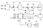
- FIG. FIG. 2 is a control block diagram illustrating an outline in a control unit according to the first embodiment.
- FIG. 1 is a system diagram illustrating a control device for an automatic transmission according to a first embodiment.
- the vehicle according to the first embodiment includes an engine 1 that is an internal combustion engine and an automatic transmission, and transmits driving force to tires 8 that are driving wheels via a differential gear.
- a power transmission path connecting the automatic transmission to the tire 8 is generically referred to as a power train PT.
- the automatic transmission has a torque converter 2, an oil pump 3, a forward / reverse switching mechanism 4, and a continuously variable transmission mechanism (belt type continuously variable transmission mechanism) CVT.
- the torque converter 2 is connected to the engine 1 and connected to the pump impeller 2b that rotates integrally with the drive claw that drives the oil pump 3, and the input side of the forward / reverse switching mechanism 4 (the input shaft of the continuously variable transmission mechanism CVT).
- a turbine runner 2c and a lockup clutch 2a capable of integrally connecting the pump impeller 2b and the turbine runner 2c are provided.
- the forward / reverse switching mechanism 4 includes a planetary gear mechanism and a plurality of clutches 4a, and switches between forward and reverse depending on the engagement state of the clutch 4a.
- the continuously variable transmission mechanism CVT includes a primary pulley 5 connected to the output side of the forward / reverse switching mechanism 4 (input shaft of the continuously variable transmission), a secondary pulley 6 that rotates integrally with the drive wheels, and a primary pulley 5 and a secondary pulley.
- the belt 7 is wound between the pulley 6 and transmits power, and the control valve unit 20 supplies control pressure to each hydraulic actuator.
- the control unit 10 includes a range position signal from the shift lever 11 that selects the range position by the driver's operation (hereinafter, the range position signal is described as P range, R range, N range, and D range, respectively), and an accelerator.
- Accelerator pedal opening signal (hereinafter referred to as APO) from the pedal opening sensor 12, brake pedal ON / OFF signal from the brake switch 17, and primary pulley pressure from the primary pulley pressure sensor 15 that detects the hydraulic pressure of the primary pulley 5 A signal, a secondary pulley pressure signal from the secondary pulley pressure sensor 16 that detects the hydraulic pressure of the secondary pulley 6, a primary rotation speed signal Npri from the primary pulley rotation speed sensor 13 that detects the rotation speed of the primary pulley 5, and the secondary pulley Secondary rotational speed signal from secondary pulley rotational speed sensor 14 that detects rotational speed of 6 Read and Nsec, and an engine speed signal Ne from the engine speed sensor 18 for detecting an engine speed, an acceleration signal G from the G sensor 19 for detecting
- the control unit 10 controls the engaged state of the clutch 4a according to the range position signal. Specifically, in the P range or N range, the clutch 4a is released, and in the R range, a control signal is output to the control valve unit 20 so that the forward / reverse switching mechanism 4 outputs reverse rotation, and the reverse clutch (Or brake). In the D range, a control signal is output to the control valve unit 20 so that the forward / reverse switching mechanism 4 rotates integrally and outputs a normal rotation, and the clutch 4a is engaged. Further, the vehicle speed VSP is calculated based on the secondary rotational speed.
- FIG. 2 is a block diagram showing a control configuration in the control unit 10 of the first embodiment.
- the control unit 10 includes a target gear ratio calculation unit 101, a deviation calculation unit 102, a feedback control unit 103, a phase compensation unit 104, an addition unit 105, a command signal divergence detection unit 106, and an oil vibration detection unit 107.
- the vehicle vibration detection unit 108, the phase compensation control unit 109, and the lockup control unit 110 that controls the engagement state of the lockup clutch 2a.
- the target gear ratio calculation unit 101 calculates a target gear ratio ir * from a gear shift map that can achieve an optimal fuel consumption state based on the APO signal and the vehicle speed VSP.
- the deviation calculation unit 102 detects the actual speed ratio ir based on the primary speed signal Npri and the secondary speed signal Nsec, which are actual values representing the state of the continuously variable transmission mechanism CVT, and the actual speed ratio ir and the target speed ratio ir Calculate the deviation from *.
- the feedback control unit 103 calculates the feedback command signal for the solenoid that controls the pulley hydraulic pressure so that the set target speed ratio ir * and the actual speed ratio ir that is the actual value representing the state of the continuously variable transmission mechanism CVT coincide with each other. To do.
- the phase compensation unit 104 calculates a phase advance amount ⁇ corresponding to the traveling state with respect to the command signal calculated by the feedback control unit 103, and calculates a phase compensation signal based on the phase advance amount ⁇ .
- Adder 105 adds the phase compensation signal to the feedback command signal to calculate the final command signal.
- the command signal divergence detection unit 106 detects whether or not the final command signal diverges. If not, the divergence flag F1 is turned off. If it is divergence, the divergence flag F1 is turned on. .
- the divergence of the command signal is detected based on whether or not the state where the frequency is equal to or higher than the predetermined value and the amplitude is equal to or higher than the predetermined value has continued for a predetermined time.
- the oil vibration detection unit 107 first, the voltage signal detected by the primary pulley pressure sensor 15 and the secondary pulley pressure sensor 16 is converted into a hydraulic signal, and the DC component (variation component corresponding to the control command) is converted by band-pass filter processing. Remove and extract only the vibration component. Then, the amplitude of the vibration component is calculated, and if the state where the amplitude of either the primary pulley pressure or the secondary pulley pressure is greater than or equal to a predetermined amplitude continues for a predetermined time or longer, the oil vibration flag F2 is turned ON. On the other hand, when the oil vibration flag F2 is ON and the state where the amplitude is less than the predetermined amplitude continues for a predetermined time or longer, the oil vibration flag F2 is turned OFF.
- the vehicle vibration detection unit 108 extracts the vibration component of the longitudinal acceleration detected by the G sensor 19, and when the state where the amplitude of the vibration component is equal to or greater than a predetermined value continues for a predetermined time or longer, the vibration flag F3 is turned ON. . On the other hand, when the state where the amplitude of the vibration component is less than a predetermined value continues for a predetermined time or longer, the vibration flag F3 is turned OFF.
- the phase compensation control unit 109 reads information on the divergence flag F1, the oil vibration flag F2, and the vibration flag F3 and the range position signal, and calculates an operating point defined by VSP and APO. Then, after the engine is started, when all the various flags are OFF, a signal permitting the output of the phase compensation signal in the phase compensation unit 104 is output. On the other hand, when any one of the flags is turned ON, a signal for prohibiting the output of the phase compensation signal in the phase compensation unit 104 is output and a command for releasing the lockup clutch 2a is output.
- the phase compensation signal is output from the phase compensation unit 104, which may increase the vibration of the command signal.
- the vibration may be amplified. Therefore, only the feedback control is made to function by prohibiting the output of the phase compensation signal. Thereby, a highly robust control configuration can be obtained.
- the mass of the power train PT can be changed from the mass obtained by adding the engine mass to the mass obtained by excluding the engine mass. Since the resonance frequency has a correlation with the mass of the power train PT, the resonance frequency can be moved and the vibration can be suppressed by changing the mass.
- phase compensation control unit 109 prohibits the output of the phase compensation signal from the phase compensation unit 104 even after the prohibition by turning on the divergence flag F1 or the oil vibration flag F2, and thereafter When all the flags are turned OFF, the following return condition is satisfied, so that the output of the phase compensation signal from the phase compensation unit 104 is resumed and the engagement of the lockup clutch 2a is permitted.
- Return condition 1 When the operating point moves (Return condition 2) When the range position signal changes Note that all flags are reset to OFF when the ignition switch is turned off, so the next ignition switch When is turned on, the engagement of the lockup clutch 2a and the output of the phase compensation signal are executed as in normal control.
- the lock-up clutch 2a has a role of directly connecting a power transmission path between the engine 1 and the automatic transmission, and contributes to improvement of fuel consumption. Therefore, there is a possibility that the fuel consumption cannot be sufficiently improved if the lockup clutch 2a is released. Vibration phenomena such as resonance occur depending on the operating point determined by VSP or APO, so if the operating point moves from the operating point at the time of vibration to another operating point, Vibration can be avoided. Therefore, when the operating point changes, the output of the phase compensation signal is resumed and re-engagement of the lockup clutch 2a is permitted. Further, when the D range is changed to the N range or the like, the state of the power train PT is changed, so that there is a high possibility that the vibration phenomenon can be avoided.
- the vibration flag F3 when the vibration flag F3 is turned ON, even if all the flags are turned OFF, the output of the phase compensation signal is prohibited until the ignition switch is turned OFF, and the lockup clutch 2a
- the signing of is prohibited. That is, in the state where the divergence flag F1 and the oil vibration flag F2 are ON, those phenomena do not necessarily appear in the vehicle behavior. If the output of the phase compensation signal is prohibited before appearing in the vehicle behavior and the divergence flag F1 or oil vibration flag F2 is turned OFF, the opportunity to start outputting the phase compensation signal again or to engage the lock-up clutch 2a Even if given, the influence on the vehicle behavior is small.
- the vibration flag F3 when the vibration flag F3 is turned ON, the actual vehicle behavior is in a state of vibration, and the output of the phase compensation signal is started again, or the engagement of the lockup clutch 2a is permitted. Is likely to give the driver a sense of incongruity due to actual vibration of the vehicle behavior. Therefore, when the vibration flag F3 is turned on, for example, even if the vibration flag F3 is turned off thereafter, the lockup clutch 2a is prohibited from being engaged.
- a continuously variable transmission mechanism CVT in which a belt 7 is wound between a primary pulley 5 and a secondary pulley 6 to control a belt clamping pressure between the primary pulley 5 and the secondary pulley 6 to change gears, and based on a running state
- a phase compensation unit 104 that performs compensation, and a phase compensation control unit 109 that stops phase advance compensation by the phase compensation unit 104 when an unstable traveling state of the vehicle is detected are provided. Therefore, it is possible to stabilize the control and to stabilize the vehicle behavior.
- the engine 1 Provided between the engine 1 (power source) and the continuously variable transmission mechanism CVT, includes a torque converter 2 having a lockup clutch 2a, and the phase compensation control unit 109 is engaged by the lockup clutch 2a.
- the lockup clutch 2a When stopping the phase lead compensation, the lockup clutch 2a is released. Therefore, by changing the mass of the power train PT, the resonance frequency can be changed and vibration can be suppressed. Even when the vehicle longitudinal acceleration is vibrated, the engine 1 and the automatic transmission can be connected via fluid by releasing the lock-up clutch 2a, and the vibration phenomenon between the drive wheels can be suppressed.
- the phase compensation control unit 109 After the phase advance compensation is stopped, the phase compensation control unit 109 returns the phase advance compensation when the operating point set based on the values of the vehicle speed VSP and the accelerator pedal opening APO changes. That is, if the operating point changes, there is a high possibility that the driving point is separated from the traveling state in which vibration occurs, and therefore the phase compensation signal can be output in more traveling states.
- the phase compensation control unit 109 After the phase advance compensation is stopped, the phase compensation control unit 109 returns the phase advance compensation when the range position of the select lever operated by the driver changes. That is, if the range position changes, there is a high possibility that the vehicle is separated from the traveling state in which vibrations occur, and therefore the phase compensation signal can be output in more traveling states.
- the phase compensation control unit 109 changes the return condition of the phase advance compensation according to the unstable traveling state of the vehicle when the phase advance compensation is stopped. In other words, even if it is determined that the vehicle is in an unstable running state, if the vehicle behavior actually shows an unstable state, the return is restricted and the control becomes unstable. If the vehicle behavior is not reflected on the vehicle, the vehicle is prompted to return, so that it is possible to secure a traveling state that can compensate for the phase advance while avoiding an unstable state.
- the phase compensation control unit 109 releases the lockup clutch 2a and then engages the lockup clutch 2a based on the return condition of the phase advance compensation.
- the engagement timing of the vehicle is unstable when the phase advance compensation is stopped.
- the divergence of command signal of the feedback control unit or oil vibration is detected as an unstable driving state of the vehicle when phase advance compensation is stopped, compared to the fastening timing in the case of the driving state where the longitudinal acceleration of the vehicle vibrates as a normal driving state
- the fastening timing in the case of the running state is earlier. Specifically, when the vibration flag F3 is turned on and then turned off, the lockup clutch 2a is prohibited from being engaged until the next ignition switch is turned off, thereby avoiding the effect on actual vehicle behavior. To do.
- the lockup clutch 2a is permitted to be engaged on condition that the operating point or the range position has changed.
- the vibration does not necessarily appear in the vehicle behavior
- the divergence flag F1 and the oil vibration flag F2 are turned off, the effect on the vehicle behavior is given even if the opportunity to re-engage the lockup clutch 2a is given again. Is small. Therefore, fuel efficiency can be improved by making it easy to secure the engaged state of the lockup clutch 2a while suppressing the influence on the vehicle behavior.
Landscapes
- Engineering & Computer Science (AREA)
- General Engineering & Computer Science (AREA)
- Mechanical Engineering (AREA)
- Transportation (AREA)
- Chemical & Material Sciences (AREA)
- Combustion & Propulsion (AREA)
- Automation & Control Theory (AREA)
- Control Of Transmission Device (AREA)
- Control Of Fluid Gearings (AREA)
Abstract
Description
図1は実施例1の自動変速機の制御装置を表すシステム図である。実施例1の車両は、内燃機関であるエンジン1と、自動変速機とを有し、ディファレンシャルギヤを介して駆動輪であるタイヤ8に駆動力を伝達する。自動変速機からタイヤ8へと接続する動力伝達経路を総称してパワートレーンPTと記載する。
(復帰条件1)動作点が移動した場合
(復帰条件2)レンジ位置信号が変化した場合
尚、全てのフラグは、イグニッションスイッチがオフとなったときにOFFにリセットされるため、次のイグニッションスイッチがオンとなった時には、ロックアップクラッチ2aの締結や位相補償信号の出力が通常制御通りに実行される。
(1)プライマリプーリ5とセカンダリプーリ6との間にベルト7を巻装し、プライマリプーリ5とセカンダリプーリ6とにおけるベルト挟持圧を制御して変速する無段変速機構CVTと、走行状態に基づいて目標変速比ir*を演算する目標変速比演算部101と、無段変速機構CVTの状態を表す実値に基づいてフィードバック制御するフィードバック制御部103と、走行状態に基づいてフィードバック制御の位相進み補償を行う位相補償部104と、車両の不安定な走行状態を検出したときは、位相補償部104による位相進み補償を停止する位相補償制御部109と、を備えた。よって、制御の安定化を図ることが可能となり、車両挙動を安定化できる。
Claims (6)
- 無段変速機構と、
走行状態に基づいて目標変速比を演算する目標変速比演算部と、
前記無段変速機構の状態を表す実値に基づいてフィードバック制御するフィードバック制御部と、
走行状態に基づいて前記フィードバック制御の位相進み補償を行う位相補償部と、
車両の不安定な走行状態を検出したときは、前記位相補償部による位相進み補償を停止する位相補償制御部と、
を備えた自動変速機の制御装置。 - 請求項1に記載の自動変速機の制御装置において、
動力源と前記無段変速機構との間に設けられ、ロックアップクラッチを有するトルクコンバータを備え、
前記位相補償制御部は、前記ロックアップクラッチが締結しているときに位相進み補償を停止するときは、前記ロックアップクラッチを解放する自動変速機の制御装置。 - 請求項1または2に記載の自動変速機の制御装置において、
前記位相補償制御部は、前記位相進み補償を停止後、車速とアクセルペダル開度の値に基づいて設定される動作点が変化したときは、前記位相進み補償を復帰する自動変速機の制御装置。 - 請求項1ないし3いずれか一つに記載の自動変速機の制御装置において、
前記位相補償制御部は、前記位相進み補償を停止後、運転者が操作するセレクトレバーのレンジ位置が変化したときは、前記位相進み補償を復帰する自動変速機の制御装置。 - 請求項1ないし4いずれか一つに記載の自動変速機の制御装置において、
前記位相補償制御部は、位相進み補償を停止したときの車両の不安定な走行状態に応じて位相進み補償の復帰条件を変更する自動変速機の制御装置。 - 請求項1ないし5いずれか一つに記載の自動変速機の制御装置において、
動力源と前記無段変速機構との間に設けられ、ロックアップクラッチを有するトルクコンバータを備え、
前記位相補償制御部は、ロックアップクラッチを解放後、前記位相進み補償の復帰条件に基づいて前記ロックアップクラッチを締結する締結タイミングは、前記位相進み補償を停止したときの車両の不安定な走行状態として車両の前後加速度が振動した走行状態の場合の締結タイミングよりも、前記位相進み補償を停止したときの車両の不安定な走行状態として前記フィードバック制御部の指令信号の発散又は油振が検知された走行状態の場合の締結タイミングのほうが早い自動変速機の制御装置。
Priority Applications (4)
| Application Number | Priority Date | Filing Date | Title |
|---|---|---|---|
| CN201780016877.1A CN108779849B (zh) | 2016-03-17 | 2017-02-17 | 自动变速器的控制装置 |
| US16/082,597 US11204092B2 (en) | 2016-03-17 | 2017-02-17 | Control device for automatic transmission |
| KR1020187026271A KR102050681B1 (ko) | 2016-03-17 | 2017-02-17 | 자동 변속기의 제어 장치 |
| JP2018505365A JP6534490B2 (ja) | 2016-03-17 | 2017-02-17 | 自動変速機の制御装置 |
Applications Claiming Priority (2)
| Application Number | Priority Date | Filing Date | Title |
|---|---|---|---|
| JP2016053191 | 2016-03-17 | ||
| JP2016-053191 | 2016-03-17 |
Publications (1)
| Publication Number | Publication Date |
|---|---|
| WO2017159203A1 true WO2017159203A1 (ja) | 2017-09-21 |
Family
ID=59850184
Family Applications (1)
| Application Number | Title | Priority Date | Filing Date |
|---|---|---|---|
| PCT/JP2017/005798 Ceased WO2017159203A1 (ja) | 2016-03-17 | 2017-02-17 | 自動変速機の制御装置 |
Country Status (5)
| Country | Link |
|---|---|
| US (1) | US11204092B2 (ja) |
| JP (1) | JP6534490B2 (ja) |
| KR (1) | KR102050681B1 (ja) |
| CN (1) | CN108779849B (ja) |
| WO (1) | WO2017159203A1 (ja) |
Cited By (1)
| Publication number | Priority date | Publication date | Assignee | Title |
|---|---|---|---|---|
| WO2019176400A1 (ja) * | 2018-03-15 | 2019-09-19 | ジヤトコ株式会社 | 自動変速機の制御装置および制御方法 |
Families Citing this family (1)
| Publication number | Priority date | Publication date | Assignee | Title |
|---|---|---|---|---|
| BE1025861B9 (nl) * | 2017-12-29 | 2019-10-14 | Punch Powertrain Nv | Stuurapparaat voor een koppeling in een aandrijflijn en werkwijze voor het aansturen van een koppeling in een aandrijflijn alsmede een aandrijflijn omvattende het stuurapparaat |
Citations (6)
| Publication number | Priority date | Publication date | Assignee | Title |
|---|---|---|---|---|
| JP2002106700A (ja) * | 2000-09-29 | 2002-04-10 | Jatco Transtechnology Ltd | 無段変速機の変速制御装置 |
| JP2004044808A (ja) * | 1997-02-27 | 2004-02-12 | Denso Corp | システム制御装置 |
| JP2005069455A (ja) * | 2003-08-28 | 2005-03-17 | Nissan Motor Co Ltd | 無段変速機の変速比制御装置 |
| JP2011174574A (ja) * | 2010-02-25 | 2011-09-08 | Jatco Ltd | 車両用ベルト式無段変速機の制御装置と制御方法 |
| JP2011207240A (ja) * | 2010-03-26 | 2011-10-20 | Toyota Motor Corp | 車両制御システム |
| JP2012220010A (ja) * | 2011-04-14 | 2012-11-12 | Toyota Motor Corp | 車両制御装置 |
Family Cites Families (19)
| Publication number | Priority date | Publication date | Assignee | Title |
|---|---|---|---|---|
| US4582185A (en) * | 1984-02-15 | 1986-04-15 | General Motors Corporation | Controlled capacity torque converter clutch |
| JP2869845B2 (ja) * | 1994-02-09 | 1999-03-10 | 株式会社ユニシアジェックス | トルクコンバータ付自動変速機のロックアップ機構の故障診断装置 |
| JPH08233095A (ja) * | 1995-03-01 | 1996-09-10 | Nippondenso Co Ltd | 自動変速機のロックアップクラッチのスリップ制御装置 |
| JP3082131B2 (ja) * | 1995-07-20 | 2000-08-28 | 本田技研工業株式会社 | ロックアップクラッチの制御装置 |
| JP3191631B2 (ja) * | 1995-08-09 | 2001-07-23 | トヨタ自動車株式会社 | 車両用直結クラッチのスリップ制御装置 |
| JP3240979B2 (ja) * | 1997-11-04 | 2001-12-25 | 日産自動車株式会社 | トルクコンバータのスリップ制御装置 |
| US6334835B1 (en) * | 1999-03-03 | 2002-01-01 | Toyota Jidosha Kabushiki Kaisha | Fuel-cut control device and fuel-cut control method |
| JP3873899B2 (ja) * | 2003-02-13 | 2007-01-31 | 日産自動車株式会社 | トルクコンバータのスリップ制御装置 |
| FR2870912B1 (fr) * | 2004-05-28 | 2007-08-10 | Renault Sas | Dispositif et procede de commande d'une boite de vitesses automatisee pour piloter les pontages et depontages |
| JP4183670B2 (ja) * | 2004-09-22 | 2008-11-19 | ジヤトコ株式会社 | 無段変速機の変速制御装置 |
| JP4133989B2 (ja) * | 2004-10-01 | 2008-08-13 | ジヤトコ株式会社 | 無段変速機の制御装置 |
| JP4116991B2 (ja) * | 2004-10-07 | 2008-07-09 | ジヤトコ株式会社 | 自動変速機の制御装置 |
| JP4317808B2 (ja) * | 2004-10-25 | 2009-08-19 | 日産自動車株式会社 | 自動変速機の制御装置 |
| JP4731153B2 (ja) * | 2004-11-04 | 2011-07-20 | 日産自動車株式会社 | 自動変速機の制御装置 |
| JP5227742B2 (ja) | 2008-10-28 | 2013-07-03 | ヤンマー株式会社 | エンジン発電機 |
| JP4924620B2 (ja) * | 2009-01-13 | 2012-04-25 | トヨタ自動車株式会社 | 車両の制御装置および制御方法 |
| EP2851586B1 (en) * | 2013-09-18 | 2016-11-30 | MITSUBISHI HEAVY INDUSTRIES, Ltd. | Hydraulic transmission |
| JP6045520B2 (ja) | 2014-02-07 | 2016-12-14 | ジヤトコ株式会社 | 無段変速機の制御装置 |
| JP6289239B2 (ja) * | 2014-04-17 | 2018-03-07 | ジヤトコ株式会社 | 車両用自動変速機の摩擦締結要素における潤滑構造 |
-
2017
- 2017-02-17 US US16/082,597 patent/US11204092B2/en active Active
- 2017-02-17 WO PCT/JP2017/005798 patent/WO2017159203A1/ja not_active Ceased
- 2017-02-17 CN CN201780016877.1A patent/CN108779849B/zh active Active
- 2017-02-17 KR KR1020187026271A patent/KR102050681B1/ko not_active Expired - Fee Related
- 2017-02-17 JP JP2018505365A patent/JP6534490B2/ja active Active
Patent Citations (6)
| Publication number | Priority date | Publication date | Assignee | Title |
|---|---|---|---|---|
| JP2004044808A (ja) * | 1997-02-27 | 2004-02-12 | Denso Corp | システム制御装置 |
| JP2002106700A (ja) * | 2000-09-29 | 2002-04-10 | Jatco Transtechnology Ltd | 無段変速機の変速制御装置 |
| JP2005069455A (ja) * | 2003-08-28 | 2005-03-17 | Nissan Motor Co Ltd | 無段変速機の変速比制御装置 |
| JP2011174574A (ja) * | 2010-02-25 | 2011-09-08 | Jatco Ltd | 車両用ベルト式無段変速機の制御装置と制御方法 |
| JP2011207240A (ja) * | 2010-03-26 | 2011-10-20 | Toyota Motor Corp | 車両制御システム |
| JP2012220010A (ja) * | 2011-04-14 | 2012-11-12 | Toyota Motor Corp | 車両制御装置 |
Cited By (1)
| Publication number | Priority date | Publication date | Assignee | Title |
|---|---|---|---|---|
| WO2019176400A1 (ja) * | 2018-03-15 | 2019-09-19 | ジヤトコ株式会社 | 自動変速機の制御装置および制御方法 |
Also Published As
| Publication number | Publication date |
|---|---|
| US20190063593A1 (en) | 2019-02-28 |
| JP6534490B2 (ja) | 2019-06-26 |
| JPWO2017159203A1 (ja) | 2018-11-22 |
| CN108779849B (zh) | 2020-04-28 |
| KR102050681B1 (ko) | 2019-11-29 |
| KR20180111995A (ko) | 2018-10-11 |
| CN108779849A (zh) | 2018-11-09 |
| US11204092B2 (en) | 2021-12-21 |
Similar Documents
| Publication | Publication Date | Title |
|---|---|---|
| JP5494839B2 (ja) | 車両制御装置 | |
| JP5870660B2 (ja) | 車両のエンジン自動制御装置 | |
| JP5790670B2 (ja) | 車両の制御装置 | |
| US10495222B2 (en) | Automatic transmission control device and control method | |
| JP4367425B2 (ja) | 車両の制御装置 | |
| WO2013011579A1 (ja) | 車両の制御装置 | |
| CN105882646B (zh) | 用于车辆的控制装置 | |
| US10527165B2 (en) | Automatic transmission control device and control method | |
| JP2010038300A (ja) | 車両の制御装置および制御方法 | |
| JP5949936B2 (ja) | 車両の走行制御装置 | |
| US10501083B2 (en) | Vehicle control device and vehicle control method | |
| JP6534490B2 (ja) | 自動変速機の制御装置 | |
| JP5708185B2 (ja) | 車両制御装置 | |
| JP2013053727A (ja) | 車両の動力伝達制御装置 | |
| JP6254367B2 (ja) | 制御装置 | |
| JP2010071297A (ja) | 車両制御装置 | |
| WO2016017201A1 (ja) | 車両の制御装置及び制御方法 | |
| JP2012225465A (ja) | 車両制御装置 | |
| JP6922071B2 (ja) | 自動変速機の制御装置および制御方法 | |
| JP2014149002A (ja) | 車両の制御装置 | |
| JP6637588B2 (ja) | 自動変速機の制御装置 | |
| JP2017032074A (ja) | ベルト式無段変速機の制御装置 | |
| JP2014105851A (ja) | 車両の走行制御装置 | |
| JP2013160278A (ja) | 車両の制御装置 | |
| JP2010071316A (ja) | 動力伝達部の制御装置 |
Legal Events
| Date | Code | Title | Description |
|---|---|---|---|
| DPE1 | Request for preliminary examination filed after expiration of 19th month from priority date (pct application filed from 20040101) | ||
| WWE | Wipo information: entry into national phase |
Ref document number: 2018505365 Country of ref document: JP |
|
| ENP | Entry into the national phase |
Ref document number: 20187026271 Country of ref document: KR Kind code of ref document: A |
|
| WWE | Wipo information: entry into national phase |
Ref document number: 1020187026271 Country of ref document: KR |
|
| NENP | Non-entry into the national phase |
Ref country code: DE |
|
| 121 | Ep: the epo has been informed by wipo that ep was designated in this application |
Ref document number: 17766210 Country of ref document: EP Kind code of ref document: A1 |
|
| 122 | Ep: pct application non-entry in european phase |
Ref document number: 17766210 Country of ref document: EP Kind code of ref document: A1 |